Embed Size (px)
Citation preview

STUDY OF HYDRAULIC AND ELECTRIC
DRIVEN DEEPWELL CARGO PUMP OPTIONS
Deltamarin Ltd 19.4.2007
REPORT

REPORT FOR PROJECT 1046
“STUDY OF HYDRAULIC AND ELECTRIC DRIVEN DEEPWELL CARGO PUMP OPTIONS”
CLIENT: HAMWORTHY SVANEHØJ
PREPARED BY: DELTAMARIN / JM
DATE: 19.4.2007
DELTAMARIN LTD.
Date Initials DESIGNED: 19.4.2007 JM CHECKED: 19.4.2007 JN APPROVED: 19.4.2007 JN
DELTAMARIN LTD Purokatu 1 FIN-21200 RAISIO Tel. +358-2-4336 300 Fax. +358-2-4380 378 Email: [email protected] File: Study of cargo pump options.doc

DELTAMARIN LTD. 19.4.2007 STUDY OF HYDRAULIC AND ELECTRIC DRIVEN DEEPWELL CARGO PUMP OPTIONS
TABLE OF CONTENTS:
0. INTRODUCTION ................................................................................... 1
1. EXECUTIVE SUMMARY....................................................................... 2
2. BASIS OF THE STUDY .......................................................................... 5
2.1 Cargo handling system review.................................................................. 5
2.2 Ship parameters ......................................................................................... 6
2.3 Power demands .......................................................................................... 8
2.4 Operating profiles ...................................................................................... 9
3. TECHNICAL COMPARISONS............................................................. 11
3.1 General arrangements............................................................................. 11
3.2 Weight ....................................................................................................... 12
3.3 Noise .......................................................................................................... 13
3.4 Control ...................................................................................................... 13
3.5 Emergency pumping................................................................................ 14
3.6 Stripping ................................................................................................... 14
3.7 Redundancy.............................................................................................. 15
3.8 Maintenance ............................................................................................. 16
3.9 Structure ................................................................................................... 16
3.10 Contamination of cargo........................................................................... 17
3.11 Environmental aspects ............................................................................ 18
3.12 Summary................................................................................................... 19
4. ECONOMICAL COMPARISONS......................................................... 21
4.1 Initial costs................................................................................................ 21
4.2 Operating costs......................................................................................... 23
4.3 Total economy .......................................................................................... 25
4.4 Sensitivity analysis ................................................................................... 26
5. APPENDICES ....................................................................................... 27

DELTAMARIN LTD. - 1 - 19.4.2007 STUDY OF HYDRAULIC AND ELECTRIC DRIVEN DEEPWELL CARGO PUMP OPTIONS
0. INTRODUCTION
Purpose of this study is to compare two cargo handling arrangements on small chemical and oil products carriers. Neither alternative arrangement contains a pump room, but both arrangements contain individual pumps for each cargo tank. The compared cargo pump arrangements are the following
• Hydraulic submersible cargo pumps (one per cargo tank). The pumps are powered by common electric motor driven power packs. This alternative is referred to as the hydraulic system.
• Electric deepwell cargo pumps (one per cargo tank). The pumps are individually controlled by frequency converters, one converter per one pump. This alternative is referred to as the electric system.
This study contains comparative analysis on three different reference vessels. These reference vessels represent typical small chemical and oil products carriers in sizes of approximately 6 000 ton, 13 000 ton and 45 000 ton in deadweight. Both systems’ technical and economical aspects are taken into consideration and compared head to head in all of the three reference vessels.
Economical and technical comparison data presented in this study is that of collected by Deltamarin. Where applicable and possible, source of data is expressed. Some of the information contained in this study is based on the experiences of owners that operate both electric and hydraulic systems onboard their fleet of tankers.
Aim of this is to provide a transparent comparison with enough background information given in order for the reader to objectively compare the two arrangements.

DELTAMARIN LTD. - 2 - 19.4.2007 STUDY OF HYDRAULIC AND ELECTRIC DRIVEN DEEPWELL CARGO PUMP OPTIONS
1. EXECUTIVE SUMMARY
In this study two alternative cargo handling solutions for small chemical and oil products tankers have been examined. The first alternative is submerged hydraulic pumps with electric motor driven hydraulic powerpacks. The second alternative is frequency converter controlled electric deepwell pumps. Neither alternative contains a pump room.
Both of these systems are applied to three reference vessels and their technical and economical aspects have been compared. The three reference vessels represent sizes of approximately 6 000 ton (vessel A), 13 000 ton (vessel B) and 45 000 ton in deadweight (vessel C).
Technical comparison of the two systems reveals the following differences:
• The electric system uses energy more efficiently and therefore requires less fuel to operate than the hydraulic system. In reference vessels the fuel savings for cargo handling range from 11% to 17%.
• The electric system requires less space outside the cargo area. In reference vessels A and B approximately 20 m2 of machinery space is saved, in reference vessel C approximately 60 m2 of machinery space is saved.
• There are some variations in weights of the systems. In vessel A the electrical system weights 6 tons less, in vessel B it weights 13 tons less, and in vessel C it weights 3 tons less.
• Electrical system has no noise problems, while hydraulic system is known for its high-pitched noise.
• Pumps of both systems have individual and independent stepless control. In both systems the nominal torque is available in a wide enough pump speed range to enable effective pumping of all relevant cargoes.
• Due to electric drive, there are no limits onboard a diesel-electric ship to the number of pumps being operated concurrently. Size of powerpacks limits the number of hydraulic pumps being operated concurrently.
• Pumps in the hydraulic system have shorter shaftlines than in the electric system. This has no effect in normal or abnormal operation of the cargo pumps. The only drawback from long shaftline is its increased sensitivity to torsional vibrations, but this issue can adequately be dealt with good design.
• In both systems the cargo is protected in a similar manner against possible contamination from hydraulic or lubricating oil.
• Both systems have about the same amount of redundancy. If need be, the electric system’s redundancy can be more easily enhanced.

DELTAMARIN LTD. - 3 - 19.4.2007 STUDY OF HYDRAULIC AND ELECTRIC DRIVEN DEEPWELL CARGO PUMP OPTIONS
• Emergency pumping can be arranged as easily in both of the systems. There are instances, however, when emergency pumping is not possible with the hydraulic system.
• Hydraulic system requires more maintenance than the electric system. However, this increased need of constant maintenance does not translate into a need of a bigger crew.
• Claims of environmental friendliness over the other system cannot be substantiated in the hydraulic system’s case. More environmentally friendly operational aspects clearly favour the electric system over the hydraulic system.
In economical comparison the initial cost is divided in two parts. Purchase cost is the money paid to the supplier of the system and installation cost is the shipyard’s cost of installing the system. In cost calculations labour costs and efficiency figures applicable to South Korean shipyards have been used.
In this case vessels A and B, respectively 6.000 ton and 13.000 ton, are equipped with one frequency converter per each cargo pump. The 45.000 ton vessel C is equipped with one frequency converter per each two pumps. However, also in vessels A and B it is possible to make a less expensive arrangement with two to four cargo pumps being controlled by a single converter1. In this case the purchase price will lower by 12 to 15% from the figures stated in this report. This also slightly reduces the space requirements and weight of the electric system, but not to a very significant degree.
1 Matrix Swichboard System, see http://www.hamworthy.com/docGallery/212.PDF

DELTAMARIN LTD. - 4 - 19.4.2007 STUDY OF HYDRAULIC AND ELECTRIC DRIVEN DEEPWELL CARGO PUMP OPTIONS
Annual costs are also divided in two parts, in costs incurred by producing power for the pump system and in costs directly incurred by the pumping system. Table 1 summarises all of these costs.
Table 1 Summary of costs (all figures in USD, rounded)
Initial costs can be regarded as annual capital costs during the vessel’s economic lifetime. The total annual costs are calculated with assuming 20 years of economic lifetime and interest rate of 8% for the capital costs.
�������� ���� �������� ���� �������� ����
� ����������
�������� �� ��� ��������� ��� ������ ������� ��������� ����������
������������ � ��� ��� �������� �������� ������� ������� ��������
������� ���������� ��������� ��������� ����������� ��������� ����������� �����������
����� ���������� ���������� ������������
� ����� ���� !�����
������������������ ������ ������� ����� ������� �������� �� ����
������������������ ���� ���� ���� ����� ����� �����
�������������������������� ����� ������ ������ ������ ����� ������
������ ��!���� ����� ���� ��� ������ ������� ���� ��� � ������
������� ���� !����� �������� �������� �������� �������� ��������� ���������
����� ��������� ��������� ���������
� ����� ��������� �� �� ����� �� ���� � �� ������ ���� ��� �� �����
� ����� ���� !����� ��� � �� ������ ������ ������� ������� � ������
������� �������� ��������� �������� ��������� ��������� ��������� ���������
����� ��������� ��������� ����������
"����� "����# "����$

DELTAMARIN LTD. - 5 - 19.4.2007 STUDY OF HYDRAULIC AND ELECTRIC DRIVEN DEEPWELL CARGO PUMP OPTIONS
2. BASIS OF THE STUDY
2.1 Cargo handling system review
The two cargo handling systems compared in this study are electric deepwell pump system and hydraulic submersible pumps system. Both of these systems comprises cargo pumps that are located in cargo tanks (one cargo pump per tank)
The hydraulic submersible pumps are powered by electric motor driven hydraulic powerpacks. The Powerpack Room is located away from the cargo area and in machinery spaces. Hydraulic power for the pumps is provided via a pressure pipeline, in which the hydraulic fluid is pressurised to over 250 bar. Hydraulic motor itself is located down in the tank, some half to two meters above the tank bottom. Hydraulic fluid is returned to the Powerpack Room by a return pipeline, in which a pressure of around 10 bars is upheld.
Respectively, the deepwell pumps are powered by the frequency converter controlled electric motors. Electric power is provided through the Converter Room, which is located away from the cargo area and in machinery spaces. Electric power is led from Converter Room to the pumps via cables and pumps’ electric motors’ speed is controlled by frequency converter. Impeller inside the pump head at the bottom of a tank is driven by the electric motor on main deck via a shaftline though the tank.
Figure 1. Electric deepwell pump system (left) and hydraulic submersible pump system (right)
DELTAMARIN LTD. - 6 - 19.4.2007 STUDY OF HYDRAULIC AND ELECTRIC DRIVEN DEEPWELL CARGO PUMP OPTIONS
2.2 Ship parameters
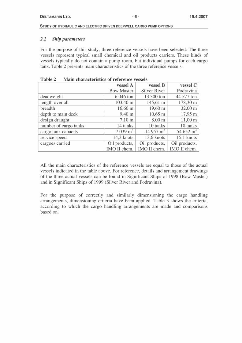
For the purpose of this study, three reference vessels have been selected. The three vessels represent typical small chemical and oil products carriers. These kinds of vessels typically do not contain a pump room, but individual pumps for each cargo tank. Table 2 presents main characteristics of the three reference vessels.
Table 2 Main characteristics of reference vessels vessel A
Bow Master vessel B
Silver River vessel C
Podravina deadweight 6 046 ton 13 300 ton 44 577 ton length over all 103,40 m 145,61 m 178,30 m breadth 16,60 m 19,60 m 32,00 m depth to main deck 9,40 m 10,65 m 17,95 m design draught 7,10 m 8,00 m 11,00 m number of cargo tanks 14 tanks 10 tanks 18 tanks cargo tank capacity 7 039 m3 14 957 m3 54 652 m3 service speed 14,3 knots 13,6 knots 15,1 knots cargoes carried Oil products,
IMO II chem. Oil products,
IMO II chem. Oil products,
IMO II chem.
All the main characteristics of the reference vessels are equal to those of the actual vessels indicated in the table above. For reference, details and arrangement drawings of the three actual vessels can be found in Significant Ships of 1998 (Bow Master) and in Significant Ships of 1999 (Silver River and Podravina).
For the purpose of correctly and similarly dimensioning the cargo handling arrangements, dimensioning criteria have been applied. Table 3 shows the criteria, according to which the cargo handling arrangements are made and comparisons based on.

DELTAMARIN LTD. - 7 - 19.4.2007 STUDY OF HYDRAULIC AND ELECTRIC DRIVEN DEEPWELL CARGO PUMP OPTIONS
Table 3 Dimensioning criteria of cargo handling arrangements vessel A vessel B vessel C capacity of each cargo pump 200 m3/h 230 m3/h 500 m3/h total simultaneous capacity 1 400 m3/h 1 380 m3/h 3 000 m3/h minimum unloading time 5,0 hours 10,8 hours 18,2 hours The main items of cargo pump systems compared in this study are also presented in the following table 4. Table 4 The main items of cargo pump systems reviewed in this study
Vessel A Vessel B Vessel C Item el-pumps hyd-
pumps el-pumps hyd-pumps el-pumps hyd-pumps
Cargo pumps
14 pcs located within cargo tanks
14 pcs located within cargo tanks
10 pcs located within cargo tanks
10 pcs located within cargo tanks
18 pcs located within cargo tanks
18 pcs located within cargo tanks
Cargo pump e-motors / hyd-motors
14 pcs located above cargo tanks
14 pcs located within cargo tanks
10 pcs located above cargo tanks
10 pcs located within cargo tanks
18 pcs located above cargo tanks
18 pcs located within cargo tanks
Power control of cargo pumps
14 converters & switchboard
Powerpacks 10 converters & switchboard
Powerpacks 9 converters & switchboard
Powerpacks
Power transmission of cargo pumps
Cabling Hydraulic piping
Cabling Hydraulic piping
Cabling Hydraulic piping
DELTAMARIN LTD. - 8 - 19.4.2007 STUDY OF HYDRAULIC AND ELECTRIC DRIVEN DEEPWELL CARGO PUMP OPTIONS
2.3 Power demands
Selection of cargo handling arrangement between the two alternatives does not influence the hull form. Some minor variations in ship’s lightweight and/or trim do take place, but they are small enough not to affect the ship’s resistance. Propulsion power requirement is thus equal for both of the alternative arrangements and can therefore be discarded from further analysis and comparison.
Power required for cargo handling differs in the two alternatives. Typical specific energy consumption of a hydraulic system is around 0,48 kWh/m3 and for electric system it is around 0,41 kWh/m3. This fact can easily be substantiated from system suppliers’ own data by comparing the electric power requirements and maximum simultaneous discard rates.
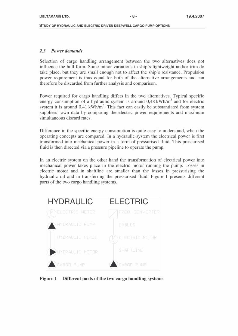
Difference in the specific energy consumption is quite easy to understand, when the operating concepts are compared. In a hydraulic system the electrical power is first transformed into mechanical power in a form of pressurised fluid. This pressurised fluid is then directed via a pressure pipeline to operate the pump.
In an electric system on the other hand the transformation of electrical power into mechanical power takes place in the electric motor running the pump. Losses in electric motor and in shaftline are smaller than the losses in pressurising the hydraulic oil and in transferring the pressurised fluid. Figure 1 presents different parts of the two cargo handling systems.
HYDRAULIC ELECTRIC
Figure 1 Different parts of the two cargo handling systems

DELTAMARIN LTD. - 9 - 19.4.2007 STUDY OF HYDRAULIC AND ELECTRIC DRIVEN DEEPWELL CARGO PUMP OPTIONS
Partial efficiencies of the two systems (generator efficiency, electric motor efficiency, hydraulic fluid transfer efficiency etc.) vary from installation to installation, but the average difference in systems’ over-all efficiencies is indisputable. Table 5 shows different power requirements for the three reference vessels. Propulsion and hotel power requirements are presented for reference only.
Table 5 Power requirements, generator power vessel A vessel B vessel C diesel-electrical propulsion, approximately
3 540 kW
4 050 kW
8 860 kW
hotel and other consumers, approximately
300 kW
430 kW
430 kW
cargo handling system, hydraulic version
668 kW
659 kW
1 432 kW
cargo handling system, electric version
588 kW
588 kW
1 188 kW
It is assumed, that all the reference vessels incorporate diesel-electrical propulsion. In a diesel-electric vessel the generators are big enough not to be disturbed by activating of short-circuit electric motors of the hydraulic version. For this reason the electrical installation onboard a diesel-electric vessel with hydraulic system does not need to be over-dimensioned.
However, if the reference vessels would be diesel-mechanical, the electrical power required by the hydraulic cargo handling system would represent majority of the total electric power required. Therefore starting of hydraulic system’s electric motors could possibly require an installation of a bigger power plant. This is of course always a case-by-case situation based on the actual power required and power output of the generator sets available. In any case such a problem does not exist in the case of frequency converter controlled electric motors, as such a system is a smooth starter.
One benefit of selection a diesel-electrical propulsion is, that it enables use of very high unloading rate in the electric cargo handling version. If the shore installation can receive, and if piping arrangements onboard allow it, all the electric deepwell pumps can be operated simultaneously at full power. In all three reference vessels the diesel-electrical power plant can provide the required amount of electric power.
2.4 Operating profiles
Individual operating profiles are compiled for all three reference vessels. The profiles are not routes of any particular ship, but examples of routes these kinds of vessels could quite typically sail. As a result estimations on the annual pumping hours for all three reference vessels are reached.

DELTAMARIN LTD. - 10 - 19.4.2007 STUDY OF HYDRAULIC AND ELECTRIC DRIVEN DEEPWELL CARGO PUMP OPTIONS
Table 6 shows the operating profiles as cumulative annual hours in different operating modes. Interested readers will find more detailed route information and calculation into the presented figures in Appendix 1.
Table 6 Annual hours in different operating modes vessel A vessel B vessel C at sea at full power 6 890 h 6 979 h 6 359 h closing port, manoeuvring
152 h 103 h 221 h
loading cargo 685 h 656 h 736 h unloading cargo 913 h 902 h 1 324 h off-hire 120 h 120 h 120 h total annual hours 8 760 h 8 760 h 8 760 h
DELTAMARIN LTD. - 11 - 19.4.2007 STUDY OF HYDRAULIC AND ELECTRIC DRIVEN DEEPWELL CARGO PUMP OPTIONS
3. TECHNICAL COMPARISONS
Technical implications of cargo pump selection can be divided into four main categories. These are the selection’s impact on ship design, operational aspects, structural aspects and environmental aspects.
Impact on ship design can be further divided to include three aspects: difference in energy consumption (already discussed in the preceding chapter), space requirements and systems’ weights. Operational aspects studied in this report include noise, control, emergency pumping, stripping, redundancy and maintenance requirements. Structural aspects include structural evaluation of different components of the pumping system as well as possibility of cargo being contaminated. Last, but not least, are the environmental aspects of cargo handling system selection.
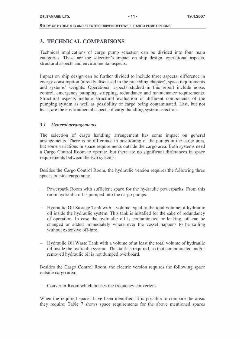
3.1 General arrangements
The selection of cargo handling arrangement has some impact on general arrangements. There is no difference in positioning of the pumps in the cargo area, but some variations in space requirements outside the cargo area. Both systems need a Cargo Control Room to operate, but there are no significant differences in space requirements between the two systems.
Besides the Cargo Control Room, the hydraulic version requires the following three spaces outside cargo area:
− Powerpack Room with sufficient space for the hydraulic powerpacks. From this room hydraulic oil is pumped into the cargo pumps.
− Hydraulic Oil Storage Tank with a volume equal to the total volume of hydraulic oil inside the hydraulic system. This tank is installed for the sake of redundancy of operation. In case the hydraulic oil is contaminated or leaking, oil can be changed or added immediately where ever the vessel happens to be sailing without extensive off-hire.
− Hydraulic Oil Waste Tank with a volume of at least the total volume of hydraulic oil inside the hydraulic system. This tank is required, so that contaminated and/or removed hydraulic oil is not dumped overboard.
Besides the Cargo Control Room, the electric version requires the following space outside cargo area:
− Converter Room which houses the frequency converters.
When the required spaces have been identified, it is possible to compare the areas they require. Table 7 shows space requirements for the above mentioned spaces

DELTAMARIN LTD. - 12 - 19.4.2007 STUDY OF HYDRAULIC AND ELECTRIC DRIVEN DEEPWELL CARGO PUMP OPTIONS
assuming a deck height of 2 800 mm. For volume figures of the two hydraulic oil tanks, please see Appendix 1.
Table 7 Space requirement vessel A vessel B vessel C powerpack room 33,0 m2 33,0 m2 75,0 m2 HO storage tank 1,6 m2 1,6 m2 2,2 m2 HO waste tank 1,7 m2 1,8 m2 2,5 m2 hydraulic version approx 36 m2 approx 36 m2 approx 80 m2 converter room 17 m2 13 m2 30 m2
In the two smaller reference vessels difference in the space required is around 20 m2. Although not a big space saving, this nevertheless opens up some possibilities in arranging the lay-out of machinery spaces.
As the cargo handling power requirements are bigger, as in reference vessel C, the difference in space requirements becomes more obvious. A space saving of 50 m2 in a 45 000 ton ship is big enough space to be usefully utilised. How this extra space is best utilised depends on the specific ship project, of course.
3.2 Weight
Difference in the two cargo handling systems’ weights can be evaluated by calculating weights of all sub-parts of the two systems. Weights of major components are available, as well as specific weights of pipes, cables and cable trays.
Please note, that the hydraulic system requires some cabling, as electric power needs to be transmitted from generators to the Powerpack Room. Similarly, electric system needs some amount of hydraulic piping for the portable emergency pump.
Table 8 shows results of weight calculations. A more detailed break-down of weights as well as used specific weights can be found from Appendix 2.
Table 8 Weight comparison (all weights in kg, rounded) vessel A vessel B vessel C hydr. electric hydr. electric hydr. electric hydraulic piping 3 220 130 3 880 170 5 630 250 designated spaces 11 700 4 390 11 750 3 350 23 900 7 740 cabling 250 5 430 250 4 780 250 12 180 pumping 22 300 21 720 21 540 16 200 49 710 58 010 total 37 460 31 670 37 420 24 510 79 480 75 080

DELTAMARIN LTD. - 13 - 19.4.2007 STUDY OF HYDRAULIC AND ELECTRIC DRIVEN DEEPWELL CARGO PUMP OPTIONS
3.3 Noise
Hydraulic cargo handling system is notorious for its loud noises. Especially the old hydraulic systems generated a lot of most unpleasant noise when operated. Older vessels with hydraulic cargo handling systems are therefore known to have been subject to operating restrictions in some ports, especially in those where there are settled areas near the port.
However, there has been a lot of progress made in combating the noise problem. Noise levels of modern hydraulic systems are significantly lower than those of the old ones. Unfortunately though, there is very little objective and quantitative comparison data available on the noise levels of the two systems. This makes quantitative comparison based on hard figures impossible.
On the other hand there are lots of qualitative and subjective data as well as a range of opinions available on the hydraulic system’s sound levels. This would suggest, that a modern hydraulic system still makes a lot less pleasant noise when operated than its electric counterpart. Even if a hydraulic system’s noise would be at a sound level comparable to that of an electric system, it is more high pitched and therefore usually considered to be more annoying.
3.4 Control
Old electric systems with two speed electric motors had problems in control of flow and pressure. As there were only two speeds the motor and the pump could be operated on, flow control was not optimal or sufficient. From technical point of view the electric motor itself had to be over-dimensioned in normal use, to be able to pump the cargoes with high specific gravity or the speed had to be reduced to a dramatically low speed.
Nowadays those problems have been solved, as the modern electric system uses a frequency converter to control the motor, in a stepless control of the pump’s rotational speed. Because of the variable speed it is possible to optimize motor and pump in a cargo system, that is able to handle cargoes within the range of specific gravity at maximum load without having an over-dimensioned motor.
Due to the frequency converter, the 50 Hz or 60 Hz networks do not limit the speed. The pump speed can alter between 0 RPM and the pump maximum rotational speed up to 3600 RPM.
With respect to control, one additional benefit of having frequency converters to control the motor is that it can be programmed to be a smooth starter. This means, that electric motor and pump can be started from zero speed and gradually increased. This reduces wear and tear of all system’s component as well as reduces generator ratings onboard diesel-mechanical ships.

DELTAMARIN LTD. - 14 - 19.4.2007 STUDY OF HYDRAULIC AND ELECTRIC DRIVEN DEEPWELL CARGO PUMP OPTIONS
The cargo system is designed to handle different specific gravity, typically ranging from 0,5 to 2,5 ton/m3. This means that the pump can handle equally efficiently all cargoes. The limitations in the discharge situation are the nominal motor power, the rated pressure of the pipe system, and the maximum pressure for the land installations.
One issue related to control is the number of pumps, which can be operated concurrently. In a diesel-electric ship there is enough power available to operate all pumps, while the number of hydraulic pumps being operated concurrently is limited by size of the power pack. However, the number of simultaneously operated pumps is also dependent on piping and segregation arrangements onboard.
As a conclusion it can be said, that the individual stepless control of each pump is possible in both systems. Nominal torque is available in a range sufficient to effectively pump all cargoes.
3.5 Emergency pumping
In case there is a failure of a single pump leading to inability to empty a tank, there really are no differences in operation in between the two systems. If one pump fails, it does not effect operation of other pumps. As a part of both systems there needs to be a hydraulic operated submersible portable pump, which can be lowered down to the cargo and used to empty the tank.
In a hydraulic system the hydraulic power is provided by the pressure pipeline and the portable pump is connected to the pipeline by hoses. In the electric system’s case there needs to be a small emergency hydraulic powerpack onboard with a fixed emergency pressure pipeline to provide the hydraulic power to any of the tanks. The emergency pumping operation itself does not differ from one system to the other. The emergency hydraulic power pack as well as the portable pump are parts of a standard scope of supply of an electric system.
In case the entire pumping system fails, due to damage of powerpack or converter room or due to damage of power providing network (pressure pipeline or electric cabling), there are differences between the two systems. In hydraulic system’s case emergency pumping is not possible, as the emergency pump requires both the powerpack and the pressure pipeline to be operational. Emergency pumping in electric system is not dependant on the main pumping system, as it is a complete stand-alone pumping system. Both the converter room and electric cabling can be completely destroyed and emergency pumping can still be done.
3.6 Stripping
Stripping procedure of cargo pumps is important especially in chemical carriers. However, it really is not a feature related to hydraulic or electric drive, but to the overall pump and impeller design. If stripping procedures of typical hydraulic and electric pumps are evaluated, significant differences are not found. It can be quite

DELTAMARIN LTD. - 15 - 19.4.2007 STUDY OF HYDRAULIC AND ELECTRIC DRIVEN DEEPWELL CARGO PUMP OPTIONS
shortly concluded, that there are no relevant differences in stripping between the two technologies.
3.7 Redundancy
It is possible to assess redundancy of a system by highlighting critical components and spaces in which a damage would cause reduced operating capability or inability to operate. Other part of reliability and redundancy assessment, likelihood of a given inability causing incident taking place, is not discussed here.
First critical space is the room, from which power is delivered to the pumping system. In hydraulic system’s case this is the Powerpack Room and in electric system’s case it is the Converter Room. These spaces do not differ in the sense, that if the space itself is damaged, the pumping system cannot be operated.
In bigger ships, like in reference vessel C, it could be useful to divide the converter room into two separate spaces. In such a case typically port and starboard side pumps are operated by separated converter rooms. This of course adds to the redundancy of operation in case of one converter room being damaged. However, if one converter room is damaged, pumps connected to this room cannot be operated from the other side, unless this has been prepared for at the building phase. But if seen necessary, very redundant arrangements can quite easily be built with the electric system.
It should also be possible to divide hydraulic system’s Powerpack Room, when nesessary. This requires extra piping and valve arrangements, so that both Powerpack Rooms still provide power to the same pressure pipeline. In case one Powerpack Room is damaged, there needs to be valve and piping arrangements so that the room can be isolated from the common pressure piping. Usually hydraulic ships are equipped with one Powerpack Room and one powerpack in it, so dividing the powerpack into two separate units will most likely add to the cost of installation. Redundant two-room arrangement is thus more complicated to arrange than in electric system’s case, but still a possible alternative.
It is also possible, that one single power providing component, a powerpack or a converter, fails. In hydraulic system’s case, if one of a typically two to four hydraulic pumps fails, it leads to reduced pumping capacity. All the pumps can be operated, even simultaneously, but as the nominal flow is not available, at a reduced capacity.
If a converter fails, the pump connected to the converter cannot be operated. It can be operated by another converter, typically the converter next to the failed one. When a converter dimensioned for one pump is operating more than just a one pump, reduced capacity is available. In this respect the situation does not differ from the hydraulic system’s case.
The next critical component is the means of transmitting power to the pumps. In hydraulic system this is by a common pressure pipeline, in electric system this is achieved by cabling on a common cable tray. In case the pipeline or the cabling is

DELTAMARIN LTD. - 16 - 19.4.2007 STUDY OF HYDRAULIC AND ELECTRIC DRIVEN DEEPWELL CARGO PUMP OPTIONS
damaged, the system can not be used. It is of course possible to enhance redundancy by building alternative pressure pipeline or cabling, but there are no differences in the two systems in this respect.
3.8 Maintenance
As the basic concepts in the two systems are different, there obviously are great differences in the maintenance requirements. It can easily be argued, that the hydraulic system is more mechanical in nature. Power distribution is by means of distributing mechanical power in form of pressurised fluid. The structure required to pressurise and distribute the hydraulic oil is comprised of mechanical components including pressure pumps, pipelines and valves.
Electric system on the other hand can easily be considered as less mechanical. Power is distributed by means of electric cabling and all in all there are very few mechanical parts in the system. The only mechanical part of the system is the power transmission from electric motor to impeller via a shaftline.
As a result of a more complicated basic concept, hydraulic system requires more maintenance than electric system. There is a difference in the amount of continuous maintenance required, but this difference is really not relevant from the shipowner’s perspective. Differences in the need for continuous maintenance are not big enough to require a bigger crew, so the theoretical difference does not come with any actual extra labour costs.
What is important from a shipowner’s perspective, is both the amount of unscheduled off-hire days due to failure of cargo system and required spare part costs. These are the two maintenance-related factors which are relevant and which directly contribute to the bottom line as reduced revenues and added costs. These items are analysed, estimated and discussed in chapter 4.2.
It can also be argued, that reduced continuous maintenance requirement of the electric system enables more preventive maintenance to be done. Hard economical figures of such a benefit are difficult to present, but the fact is nevertheless worth taking into account.
3.9 Structure
Structural solutions in the two pump concepts differ somewhat. In hydraulic system the pump head and the motor running it are both submerged at the bottom of the tank. In electric system the electric motor is located on main deck and the pump head is driven by a long shaft.
Hydraulic pump’s only structural benefit is, that it’s motor is located very near the pump head. The shaft driving the pump head is only a half to two meters long and therefore not subject to excessive alignment requirements for example. The hydraulic motor is driven by high pressure hydraulic oil in 250+ bar, and lubricated by the

DELTAMARIN LTD. - 17 - 19.4.2007 STUDY OF HYDRAULIC AND ELECTRIC DRIVEN DEEPWELL CARGO PUMP OPTIONS
return hydraulic oil. All parts of a hydraulic pump needing lubricating are actually lubricated by the hydraulic oil.
Electric pump’s motor on the other hand rests on the main deck and the pump head, at the bottom of the tank, is driven by a shaft. Shaft’s bearings are lubricated by pump’s own oil reservoir. The oil used to lubricate the bearings is actually the same kind of oil as the one used in the hydraulic system as the hydraulic oil. So just as in the hydraulic system, all lubricating needing parts of the system are lubricated by a designated lubricating oil.
Electric system’s structural drawback when compared to the hydraulic system is in its long shaft. In reference vessels the shafts are 8 100, 9 100 and 15 300 mm in length. They are all supported by one intermediate support to the ship’s structures, while the longest of the three shaftlines has two such supports. The only drawback in having a long shaft is increased possibility of torsional vibrations. However, with good design this can be avoided.
The long shaft will not make any problems during normal or abnormal operation. In the event that the pump head is being damaged, the long shaftline behaves in an identical manner to the short one. The long shaft is supported by bearings at the top of pump head and connected to a short shaft driving the impeller. In case the impeller inside the pump head becomes damaged and unevenly balanced, resulting is a vibrating mass at the end of a short shaft in both cases. In such a case the hot spots would be the top of the pump head and the connection of pump and main deck. Also in this case the only difference between the two systems lies in torsional vibrations.
On the other hand, damaged pump motor is more easily repaired in the electric system’s case. As the hydraulic motor is located down in the tank, the electric system’s pump motor is conveniently on main deck, where it is more easily accessible.
3.10 Contamination of cargo
Protection against contamination of cargo has been taken care of identically in both of the systems. In hydraulic system the high pressure hydraulic oil pipe is surrounded in the tank by the lower pressure return pipeline up to the main deck. In electric system the shaftline is surrounded by lubricating oil. The only difference is, that electric system’s oil is not pressurised, where hydraulic system’s oil is under about 10 bar pressure.
In both systems there is a contaminating preventing cofferdam surrounding the lubricating/hydraulic oil and separating it from the cargo tank. Operating manuals of both systems require purging of the cofferdam once during each trip, for that possible leakage is detected.
It is of course also possible, that lubricating or hydraulic oil is contaminated by cargo. In electric system’s case only one pump’s bearings and shaftline would be

DELTAMARIN LTD. - 18 - 19.4.2007 STUDY OF HYDRAULIC AND ELECTRIC DRIVEN DEEPWELL CARGO PUMP OPTIONS
damaged, whereas in hydraulic system’s case the entire hydraulic system would be contaminated. This would require changing of the entire hydraulic oil and could damage hydraulic system’s components. However, due to existence of a cofferdam as well as the 10 bar overpressure, such an event is fairly unlikely.
3.11 Environmental aspects
Environmental aspects are nowadays becoming more and more important. Public awareness of environmental problems has increased and global environmentalism is commonly considered to be one of the megatrends affecting business and everyday life in the 21st century. Importance of environmentalism is difficult to over-emphasise.
Arguments of environmental friendliness can be, and usually are based on a variety of facts. Low energy consumption during manufacturing or operating, use of recycled or recyclable components, structural arrangements leading to no-spill accidents or incidents, use of non-toxic materials, lower emissions and so on are all arguments commonly used.
However truthful, all of these arguments only represent different parts of the spectrum of environmental concerns. Optimising any one of these aspects is only sub-optimising in environmental sense. The only counterargument-proof claim can be, that the product is more environmentally friendly than its competitors from lifecycle analysis’ (LCA) point of view. In such an analysis all factors having an effect on manufacturing, transportation, retail, use, maintenance and disposing of a product are examined, their environmental impact is assessed and finally calculated together.
Unfortunately, LCA is very difficult, time consuming and expensive to conduct. Therefore only a few consumer products have been rated according to it. Thus it needs to be admitted, that it is impossible to obtain a complete and comprehensive evaluation of environmental aspects of the two cargo handling systems.
However, having said that, it is still possible and very fruitful to evaluate the two systems in respect of different environmental aspects individually. In any case this actually is the way different solutions are evaluated against each other today. As the big picture is blurred, this is what the arguments are usually based on.
Consumption of energy during operating is clearly favouring the electric system. By using an electric system the same amount of cargo can be pumped with a lesser amount of energy consumed. On reference vessels in terms of fuel oil annually, this translates into savings of 11..17%, from 15 tons in the smallest vessel to 65 tons in the biggest reference vessel. For details, please see Appendix 1.
Lower emissions during operating are also clearly favouring the electric system. During normal operation neither system directly emits, but they both require energy to operate. As the energy is produced in an identical way for both systems, the

DELTAMARIN LTD. - 19 - 19.4.2007 STUDY OF HYDRAULIC AND ELECTRIC DRIVEN DEEPWELL CARGO PUMP OPTIONS
amount of emissions per energy consumed is equal. The more energy consuming system thus also causes more indirect emissions.
Additionally, during abnormal operation the hydraulic system may emit hydraulic oil. Hydraulic pipelines are located on main deck, where they regularly come into contact with the salty seawater. As time passes they will slowly rust and start to leak. Obviously, in a particular ship it is possible to construct the entire pipeline with stainless steel and to maintain it well enough to prevent it from leaking. But since on the average the hydraulic systems leak oil into the world’s oceans, from LCA’s point of view these are emissions caused by operating the hydraulic system.
Emissions of hydraulic oil are very inconvenient, especially if they take place in harbour or near the coast line. Such incidents are never good for business and always bad publicity. National procedures in case of an oil spill differ somewhat, but as a ground rule it can be said, that an oil spill in a developed country will irrevocably get the attention of authorities.
Manufacturing of the two systems does not seem to contain any significant differences. Both systems include quite similar electric motors and steel and stainless steel parts. Possible differences lie in frequency converters and in hydraulic powerpacks and pipes. Without more in-depth knowledge of differences in the manufacturing processes and transportation needs it is impossible to conclude anything more definite.
Based on the information available, nothing very definite can be said about disposing of the systems either. Like in manufacturing, similarities lie in the electric motors and in steel and stainless steel parts. Differences lie in disposing of frequency converters, hydraulic powerpacks, pipes and the hydraulic oil.
As a conclusion it can be said, that environmental aspects connected in operating the system clearly favour the electric system. It can also be concluded, that there are no environmental aspects favouring the hydraulic system. A claim of hydraulic system’s higher environmental friendliness can thus not be substantiated. On the other hand, claim of electric system’s higher environmental friendliness does have merit.
3.12 Summary
Table 9 summarises and presents results of technical comparison between the two systems.

DELTAMARIN LTD. - 20 - 19.4.2007 STUDY OF HYDRAULIC AND ELECTRIC DRIVEN DEEPWELL CARGO PUMP OPTIONS
Table 9 Summary of technical comparison hydraulic system electric system energy consumption requires more energy to
operate requires less energy to operate
space requirement outside cargo area (excluding cargo control)
36 m2 in vessel A 36 m2 in vessel B 80 m2 in vessel C
17 m2 in vessel A 13 m2 in vessel B 18 m2 in vessel C
weight of system 37 ton in vessel A 37 ton in vessel B 79 ton in vessel C
32 ton in vessel A 25 ton in vessel B 75 ton in vessel C
noise makes high pitched noise no noise problems control individual stepless control,
nominal torque available for all cargoes, number of concurrently operated pumps limited by size of powerpack
individual stepless control, nominal torque available for all cargoes, in a diesel-electric ship all pumps can be concurrently operated
emergency pumping easily possible in case the pressure pipeline or powerpack is not damaged
always easily possible, even if the entire main pumping system is destroyed
redundancy fair redundancy, can be increased with a moderate effort
good redundancy, can be increased with an easy effort
maintenance requires more maintenance
requires less maintenance
structure impeller driven by a short shaftline pump motor more difficult to access
long shaft more sensitive to torsional vibrations pump motor easily accessible
contamination of cargo cargo well protected cargo well protected environmental aspects environmental friendliness
can not be substantiated more environmentally friendly due to operational aspects

DELTAMARIN LTD. - 21 - 19.4.2007 STUDY OF HYDRAULIC AND ELECTRIC DRIVEN DEEPWELL CARGO PUMP OPTIONS
4. ECONOMICAL COMPARISONS
This chapter presents the cost calculations. The text itself contains all basis and initial assumptions used in calculations as well as the final results. An interested reader will find more detailed calculations and all relevant intermediate results in Appendix 1.
4.1 Initial costs
Initial costs are best divided in two parts, in purchase costs and in installation costs. Purchase cost is the amount of money a shipyard or owner has to pay to the system supplier for a typical scope of supply. Purchase cost includes all required equipment, but not the installation.
This part of initial cost is of course very much dependant on the market situation and competition. The estimates of purchase price can therefore somewhat differ from quotes shipyards and owners receive. On the other hand, this part of cost estimation is the easiest one to replace in yards/owners own calculations, as the actual purchase price will be clearly expressed in offers they receive.
Purchase prices of electric systems are the actual offers Hamworthy Svanehøj made for the reference vessels. Purchase prices of hydraulic systems are calculated based on Deltamarin’s price data. Table 10 at the end of this subchapter presents all initial costs in one table.
When estimating installation costs it has been assumed, that the reference vessels would be built in the Far East. For this reason average labour cost and productivity figures applicable to South Korea have been used. In the following basis for used figures are explained, while the figures used can be found in Appendix 1.
− Specific price of labour has been calculated by dividing the average monthly wage in the South Korean manufacturing industry2 by average monthly working hours3 and by adding social costs of 15%4. Average South Korean shipyard’s overhead cost of 20%, based on Deltamarin’s own experience, has also been added to the average hourly wage.
− Required length of hydraulic piping is easily calculated when vessels’ main dimensions and typical lay-out drawings are known. However, choice of pipe material is up to the owner. While some owners require all pipes to be made of
2 Principal Economic Indicators, 10. Employment & Wages, National Accounts. Bank of Korea. Republic of Korea 2005.
3 South Korea, Foreign Labor Trends. California Trade and Commerce Agency. USA 1997. 4 Embassy of Republic of Korea to Finland.

DELTAMARIN LTD. - 22 - 19.4.2007 STUDY OF HYDRAULIC AND ELECTRIC DRIVEN DEEPWELL CARGO PUMP OPTIONS
stainless steel, some are satisfied with all pipes being made of steel. To represent somewhat typical solution the pressure pipes are calculated as steel pipes and the return pipes as stainless steel pipes.
− Pipe installation efficiency is based on Deltamarin’s own experience. The stated efficiency for the given average pipe size includes all working phases required, like installation, connecting, flushing, cleaning and testing. Installation efficiency of stainless steel pipes is clearly smaller than that of steel pipes.
− Required area of Powerpack Rooms is calculated by fitting the required number of hydraulic power packs into the rooms.
− Required area of Converter Rooms is calculated from lay-out drawings of the converters, supplied by Hamworthy Svanehøj.
− Required volume of Hydraulic Oil Storage Tank is calculated from volume of the hydraulic oil system. The Hydraulic Oil Waste Tank is assumed to be 10% bigger than the storage tank.
− Steelwork efficiency is based on Deltamarin’s own experience for typical steel structures required to form boundaries for Powerpack and Converter Rooms and Hydraulic Oil Tanks. Yards specialised in building cargo ships typically achieve efficiencies as high as 20 to 30 h/ton, but these figures are applicable to only hull structures with high plate thickness.
− Lubricating oil of electric pumps is the same oil as is used as hydraulic oil in the hydraulic system. Amount of lubricating oil is calculated from Hamworthy Svanehøj service manual and amount of hydraulic oil is calculated from the volume of the hydraulic system (twice, as the storage tanks needs to be filled as well). Price of lubricating/hydraulic oil is that of Shell Tellus 46 in March 2007.
− Pumping system supplier provides its part of commissioning in a standard scope of supply. It has been assessed, that there are no differences between the two systems with respect to yard’s labour requirements in installing the pumps.
− Need for cables and cable trays can be calculated as easily as the need for hydraulic piping from the vessels’ lay-out drawings.
− Cable installation efficiency is based on Deltamarin’s own experience and is expressed as labour required per cable tray length. Approximately a third of the cost of cable installation comes from installing of cable trays and mechanical shielding, a third from making connections and a third from cable installation and packing.
− Specific prices of hydraulic piping, shipbuilding steel, cables and cable trays are those of suppliers of these products.

DELTAMARIN LTD. - 23 - 19.4.2007 STUDY OF HYDRAULIC AND ELECTRIC DRIVEN DEEPWELL CARGO PUMP OPTIONS
Table 10 shows the results, when all of the above data is applied to the reference vessels. All figures are presented in USD and rounded. More detailed figures can be found from Appendix 1.
Table 10 Initial costs (all figures in USD, rounded)
4.2 Operating costs
Operating costs are best examined, when they are divided into two main parts. The first part includes running costs associated with power production for the cargo handling system. These costs can further be divided into fuel oil, lubricating oil and maintenance costs.
Calculating these costs is quite straight forward, as the annual power consumption is a direct result of energy consumption and operating profile. Specific fuel and lubricating oil consumption per power produced are both commonly available and known figures. The specific maintenance cost of power plant is a figure based on Deltamarin’s own experience and includes both spare parts and labour required to maintain the power plant on an average.
The second part of operating costs consists of costs incurred by the cargo handling system itself. As already discussed in chapter 3.8, differences in the need of continuous maintenance are not included in this calculation. Because there are no differences in crew requirements, neither system comes with any actual extra direct maintenance related labour costs.
However, from shipowner’s perspective the amount of unscheduled off-hire days due to failure of cargo system is very important. Similarly, required spare part costs are very relevant as well. Both of these directly contribute to the bottom line as reduced revenues and/or added costs.
Hydraulic system’s average spare part costs can be reliably estimated based on shipowner’s experience. Dividing annual fleetwide hydraulic system’s spare part costs by theoretical maximum pumping hours (annual pumping hours times number of pumps) a reliable specific cost figure is obtained. Such a calculation yields hydraulic system’s specific spare part cost, which is presented in Appendix 1. When
�������� ���� �������� ���� �������� ����
%�������� � � ! �������� �������� �������� �������� ��������� ��������
#����� !�������! ����� �� �������� �������� �������� ������� �������� ��������
� ������ !���� �& � �������� ������� �������� ������� �������� �������
$�'�� ! ������� �������� ������� �������� ������� ��������
(������ ��������� ����� ��������� �������� ��������� �������� ��������� ���������
)�������� ��������� ��������� ����������� ��������� ����������� �����������
(������ ������$��� ����������� ��������� ����������� ����������� ����������� �����������
����� ���������� ���������� ������������
"����# "����$"�����

DELTAMARIN LTD. - 24 - 19.4.2007 STUDY OF HYDRAULIC AND ELECTRIC DRIVEN DEEPWELL CARGO PUMP OPTIONS
this figure is applied to theoretical maximum pumping hours of reference vessels, estimated annual spare part cost per vessel is achieved.
Electric system’s spare part costs can be estimated by analysing servicing intervals of different parts of the system. In an electric system there are very few servicing or replacing needing parts. The only regularly replacing needing parts are the shaft seals of the pumps, which needs to be changed at certain intervals depending on the actual cargo operating condition of the vessel. In addition to this the shaft lubricating oil will need to be drained and refilled at the same time. For the purpose of this study, it is assumed that the shaft sealings will need replacing a total of three times in the vessels 20 years economical lifetime. No other mechanical parts in the pump system need replacing. The other wearing mechanical parts are the shaft and electrical motor bearings and converter cabinet cooling fans. During a normal vessel’s lifetime none of these parts is forecasted replacement.
However, it is unrealistic to assume, that electric system would be this trouble free. In any case there are problematic individual products and unforeseeable events, which cause spare part costs. Although there have been only few problems with modern electric motors and although field failure rate of frequency converters is below 1%, for the sake of a realistic evaluation, unexpected spare part costs have to be considered.
To be on a safe side, the unexpected spare part costs are best over-estimated. For the purpose of this study it is assumed, that in all three reference vessels a major failure of electric system occurs after 20 000 theoretical maximum pumping hours. Let’s further assume, that this major failure is in the magnitude of one frequency converter or electric motor being completely destroyed and in need of replacing. By assuming this very high failure rate it is possible to compare electric system’s spare part costs with the actual spare part costs of hydraulic system.
When operated, the pumps consume some lubricating and hydraulic oil. According to service manual the electric system’s pumps’ shafts’ lubricating oil needs to be replaced after 2 000 hours of operation. This oil changing interval has been used to calculate the pumping system’s oil costs.
There is no fixed hydraulic oil changing interval in the hydraulic system. On regular basis oil samples need to be taken to monitor the oil quality. However, 2 000 hours of operating is a good average estimate for the hydraulic oil changing interval. Table 11 presents all the relevant annual operating costs.

DELTAMARIN LTD. - 25 - 19.4.2007 STUDY OF HYDRAULIC AND ELECTRIC DRIVEN DEEPWELL CARGO PUMP OPTIONS
�(�'����� � ����� ���� !������*������!����� �+,�-���� ��.�
Difference in the amount of unscheduled off-hire days due to failure of cargo handling system is also an important operating related cost. Off-hire is expensive, as through lost revenues it can directly be seen in the bottom line. Unfortunately though, reliable and objective data on the average off-hire days is not available. Average spare part costs, for example, could be used to estimate the difference, but no such estimations are included in these calculations.
4.3 Total economy
Total economy of the two different cargo handling systems can be calculated, as both initial and annual operating costs are known. For the purpose of estimating the one-time initial payment and recurring annual payments, some method needs to be used to consider both of these costs equally and to account for the time factor and price of money.
The method used considers the initial one-time payment as a loan. The ‘loan’ is paid back in partial payments of similar sizes during the economic lifetime of the vessel. This partial payment can directly be added to annual operating costs as capital costs and thus total annual costs are obtained. Table shows results of such a calculation with assumptions of 8% as the applied interest rate and 20 years as the economic lifetime of the vessel.
Table 12 Total economy as annual costs (all figures in USD, rounded)
If in a given case the initial cost of one system is higher and operating costs lower than it rival’s, it is possible to calculate a payback time or break-even point. In none
�������� ���� �������� ���� �������� ����
�������������� ������ ������� ����� ������� �������� �� ����
��"������� ���������� ���� ���� ���� ����� ����� �����
#���������������� ����� ������ ������ ������ ����� ������
(����� �/�� ������� �������� �������� �������� �������� �������� ��������
��"�$�!%���������������� ������ ��� ��� �� ���� ������� ����
&��������������� ���� �� ����� �� ������� ���� �� ������� � ������
(����� �& � !�����& �������� �������� �������� �������� ��������� ��������
����� ��������� ��������� ���������
"����� "����# "����$
�������� ���� �������� ���� �������� ����
� ����� ��������� �������� �������� ��������� �������� ��������� ���������
� ����� ���� !����� �������� �������� �������� �������� ��������� ���������
������� �������� ��������� �������� ��������� ��������� ��������� ���������
����� ��������� ��������� ����������
"����� "����# "����$

DELTAMARIN LTD. - 26 - 19.4.2007 STUDY OF HYDRAULIC AND ELECTRIC DRIVEN DEEPWELL CARGO PUMP OPTIONS
of the reference vessels this is the case, as the hydraulic system is more expensive in light of both initial and operating costs.
4.4 Sensitivity analysis
These calculations are of course dependant on the initial assumptions made. By altering the initial assumptions, or boundary conditions, different results are obtained. In the following some initial assumptions and significance of altering them are discussed.
Heavy fuel oil price has an effect on the annual operating costs. Because hydraulic system needs more fuel, lower fuel price would favour it. Applied fuel price is quite high historically, but altering it has very little effect on total economy. Even if HFO-price would be halved, the basic results would not differ.
Alterations in operating profile have impact on all operating costs. As all operating costs are higher in hydraulic system, the system would benefit from not using it. However, significance of altering the profiles is quite small. Even if all the pumping hours would be halved, basic results would not differ.
Price of labour has also influence on the final results. It does not affect the operating costs, only the installation costs. As installing of hydraulic system requires more labour, lower price of labour would favour it. But mere labour price change is unrealistic, since the price of labour is dependant on the ship’s building country. As there are great differences is prices of labour among the Far Eastern countries, also the efficiency of labour is different. As known, low price of labour usually correlates with low efficiency.
However, to test the influence of change in price of labour, in calculations the price can be changed without changes in efficiency. By lowering the price of labour even by 70% from the South Korean actual value, there will be no differences in the final results.
Interest rate applied in the total economy calculation has no effect on the final results, even if the rate used would be 0.

DELTAMARIN LTD. - 27 - 19.4.2007 STUDY OF HYDRAULIC AND ELECTRIC DRIVEN DEEPWELL CARGO PUMP OPTIONS
5. APPENDICES
Appendix 1 Cost Comparison (five pages)
Appendix 2 Weight comparison (one page)

������������
������������
���������
�� ������� � �������
��������� �������� ��������� �������� ��������� ��������
�����������
�������� ��� ��� � ��� ��� � � ��� ��� � ��� ��� � � ��� ��� � � ��� ��� �
����� ���� ��� ��� � �� ��� � ��� ��� � �� ��� � ��� ��� � ��� ��� �
���������������� ���� !" #! � �" �$%&���" �#�$!%" ��&!�#" �%��%%�"
��''����� ( �����" (&!&��&" (� # ��"
�����)�����*�����
!" #� �$�� � ��� �� ��� � �� ��� � �� ��� � �� ��� � �� ��� � �� ��� �
%" #� �$�� � ��� ��� � ��� � ��� � ��� � � ��� � � ��� �
����������� # �$�� � ��� � ��� � � ��� � � ��� � � ��� � � ��� � � ��� �
������& ������ �� ��� � �� ��� � �� ��� � �� ��� � ��� ��� � �� ��� �
������)�����*����� �$�#�" %� " #��!�" $� �#" ��&�&�" ����$�"
��''����� ($# ��" (�%%� " (%$�!�"
������)��������� �� ��� � �� ��� � ��� ��� � �� ��� � ��� ��� � ��� ��� �
�����)�����*����� �� ��� � �� ��� � �� ��� � �� ��� � ��� ��� � ��� ��� �
�������������� �%��&$" ��$ &" ��� %�" �$!� �" &�$�$�" ! $!"
��''����� (%����" (%�� �" (��!�!�"
+���,(�-�)����'��� �-�� �-�� �-��
��� ' �������� ����(
�� ����� ��) ����)�� *� �� # � +�,
� #�&���� �� +�,
�-����&� ����� ���). � ,// 0 ������ +�, 1��������2
� 3+4 0 ������ +�, 1��������2
������ �#����� #
����� ������ ��� �� �� �� ���) �������&
-������ -�����+ -�����.
��&� � # �

������������
������������
���������
�� ������� � �����������
��������� �������� ��������� �������� ��������� ��������
��������������
������ � ����� ������ ��� � � � ��� � � � ��� � � �
������ � ��������� ����� ������ ��� � � � ��� � � � ��� � � �
������ � ������� ���� ������ ��� � ��� � ��� � ��� � ��� � ��� �
������ � ��� ������ �� � �� � �� � �� � �� � �� �
� �!���� !�� �� ��� " � ��� " �� ��� " � ��� " �� ��� " � ��� "
����������� !�� �� ��� " � ��� " �� ��� " � ��� " �� ��� " �� ��� "
���� ��� !"#!$% �#&$&% '($)$% �"')�% �"$("*% )#))(%
+������ ,���������������
# � �$����!%��� �� �� � �� �� �� � �� �� �� � ��
# � !�&�������� � �� �� �� � �� �� �� � �� �� ��
' � �()�� �� ������ ���% ���� �� ���� �� ���� �� ���� �� ���� �� ���� ��
' � �()�� �� $���� ���% ���� �� ���� �� ���� �� ���� �� ���� �� ���� ��
!�� � �$����!%��� �� ��� " � " �� ��� " � " �� ��� " � "
!�� � !�&�������� � " �� ��� " � " � ��� " � " �� ��� "
!�� � �()�� ��! �� ���%� � ��� " � " � ��� " � " � ��� " � "
���� ��� )!!&!% �)"#(% )!$"#% '*�#% (''))% �"#)'%
�������� ,�����
��* � !��� � ��� " � ��� " � ��� " � ��� " � ��� " � ��� "
!�� � � *���()�� ��! �� �� ��� " ��� " �� ��� " ��� " �� ��� " � ��� "
���� ��� )"!(&% "#")% )"*!&% )*�)% """#$% ($&&%
-�����
������ � !�*���� �� � ��� � �� � ��� � �� � � ��� �
������ � !�*�� ���(� �� � ��� � �� � ��� � �� � ��� �
�������� !��� � ��� " �� ��� " � ��� " �� ��� " � ��� " �� ��� "
����������� !��� �� " � ��� " �� " � ��� " �� " � ��� "
���� ��� )#)#% ")!$�% )#)#% "()!*% )#)#% &)&*!%
. ������������ � ��� �)&&)�% ($$#*% �*'�((% &�#�!% )""!$(% �#�!&$%
��� ��� ��� �� +�,
/������ /�����+ /�����-
���� � � �

������������
������������
���������
�� ������� � ���������
��������� �������� ��������� �������� ��������� ��������
�������������
�������� ������� ��������
��� � �� ����������� !!" #$ %"" #$ !%� #$ %"" #$ � �&� #$ � �"" #$
'����� ������� (��� ��& ( ��& ( ��� ( ��� ( � &�� ( � &�� (
��� � �� ��������� !�� )$( %&� )$( %�� )$( %&� )$( � "�! )$( � %�& )$(
*����� � �� ��������� !�� )$( %!% )$( !�% )$( %%" )$( � ��! )$( � !%! )$(
+��� �� ��������� ��& �� ��" �� ��� �� ��� �� &"& �� &�" ��
,�-�������� �� ��������� &�� #� �"& #� &�& #� ��� #� ��" #� "�" #�
+��� �� ���� �� !�" . �� &�� . �! "�� . �� ��% . "% "%� . �� �&� .
,�-�������� �� ���� !�� . %�& . !%� . %"! . � ��! . � �&� .
)���������� ���� � ��� . � ��� . � ��� . � ""� . ! ��� . % %�" .
�������� !"# $ %#&!'$ %(#'!$ %#"&&$ ("#("$ '&)#($
����� / ����� / ����� /
*�����������������
)���������� ��-�� ����
,�-��(�������� �� ���� � ��" . ��� . � �&� . ��! . �� �!� . ��� .
0���� ���� ���� �" "�� . �� "%� . &� %�� . �� ��� . �� �"" . �� ��� .
�������� ) '(($ ���%#$ (" ($ �"(!&$ �!�%)'$ "%)&!$
������+����������� &"%#%$ '( $ #(�!($ "� (#$ �()()�$ �%��"($
���
���%
�����& #$(��&
��� ��#$(
��%� ��#$(
��� .���
� ��� .���
� �%� .���
&�&" .�)$(
&�"& .�(�����
�����1�� ����������� ��� 1 � �� �����
�����1�� ����� ���� ��� 1 (�������� ������
2$������� 30* ���������4
2�������4
2�������� %�&�����4
20(��� 5����� �!4
2*���������4
2� ���4
����� 1 (��6� 1��� ��
,�����*
& ��� �&�(� ��� �&�( � &"� �&�(
����� 1 ��-���������(�������� �� 1� �����
,������ ,�����-
�����1�� ������ ��������� 1 (�������� ������
�����1�� 1��� �� ��������� 1 � �� �����
�����1�� ��-�������� �� ��������� 1 � �� �����
������6��� ������6���
.������
����� 1 ��-�������� �� 1� � �� �����
2����������4
2�������4
������6���
�������/�/�������
��������� �11�������
���� � 1 �

������������
������������
���������
�� ������� � ��������� �������
�����������
�����
��������� �������
������
����
������
����
�������
����
������
����
�����
����
�������� ��� �
�������� �� ���� �� ��! �� �"�� � #�� � ��� � �!�� �
�������� ���$ ���� �� #�" �� ���� � ��" � #�� � #�� � #��� �
%���� ���$ ���� �� "## �� #��# � ��" � ��� � ��� � #��! �
�������� ���� ��� �"� �� ���� � ��� � ��� � ���� �
����� � !" # " �# " � " ��$ !"
&�' !�� �
(����)��� �� ���� �� ��� �� "��" � ��" � ���� � ��� � ���� �
*�������� )������ ��" �� ##�� � ��� � ��� � !�� � ���� �
&�' ���� ��� � ��� �� !��" � ��� � ���� � ����" �
����� �% #" # &" ## " �! " #� %"
&�' ���� �
�������� �� ���� �� #�� �� ���� � ��" � ��� � ��� � �!�� �
�������� �� ���� �� #�" �� ���! � ��� � ��� � ��� � #��! �
%���� �� ���� �� "## �� #"�# � ��" � ��� � ��� � ���! �
&�' )������ �� �� ��� � ��� � ��� � �"�� �
����� '! (" $ " �' " � " ��% ("
��������������
��������)����*��
����������������)����
������
)������
���+"���
����� '%! "
����
� ��� �
��# �
��� �
��� �
'%! "
����
� !�� �
�"� �
��# � � #�� �
��� ���� �
'%! "
������,
�#��
� #"� �
��� �
�!" � �"� � �#� �
�������
������-
������,
������-�������
���� � � �

������������
������������
���������
�� ������� � ����� ����
������� ������� �������
������ ��� ��� ��� �� ��� � ��!�"� � ��#� � �
������ $��%��� ���������&���� ��' ����� � � #�!� � ��!��� �
������� �� ()� �()� �"�"� � ���"� � ���� �
(���� � ���� ���* (���� ���� � ���"! � ����! �
(��&��� � ()� +()� ���� � #��� � ����� �
����%����� " ��" �� � �� �� �� !�� ��
������ , ���� ���� ����� � �#��� � �����! �
�&�$�� , ���� ���*���&��� �� �&��� �� �&��� �# �&���
������� ��� ��� ��� ���� �
�����,�� ����� , ��$&� ���� -��&� .��� ��/�0
�����,�� ����� , ����� "�! -��� .�&������0
�����%�* �,,������1 !! ���� .(���������0
�����,�� ����� , ����� ���&��&��� ���! -��� .����&�����0
�����,�� ����� , ���������� �#� -���
.(���������0
�����,�� %����� , ������� ����� "# *����
.�1�����0
�����,�� %����� , ������� ����� �# *����
.�1�����0
�����,�� %����� , ������� ������ #" *����
.����&�����0
�����,�� ��$�� ��� � �!! -�� .�&������0
�����,�� ��$�� ���1 ��� �""� " -�� .�&������0
��$�� ����������� �,,������1 ���� ��� .(���������0
�����,�� ����� , ��$�� ����������� ���� -�� .����&�����0
����� ���� ����������� �,,������1 ��"� ���2 ,� � ! ���� ���� .(���������0
3������ ���� ����������� �,,������1 ����" ���2 ,� � " ���� ���� .(���������0
3������ ���� ���� ����������� �,,������1 �!� ���2 ,� � � ���� ���� .(���������0
�����,�� ����� ���� ����������� ��� !�� � -�� .����&�����0
�����,�� 3������ ���� ����������� ��� �!���# -�� .����&�����0
�����,�� 3������ ���� ���� ����� ��� #� -�� .����&�����0
�����,�� ����� ���� �������� ��� �����# -�� ! ���� ���� .�&������0
�����,�� 3������ ���� �������� ��� �"���# -�� " ���� ���� .�&������0
�����,�� 3������ ���� ���� �������� ��� �"��� -�� � ���� ���� .�&������0
�����,�� ��� ���� �������� ��� ����� -�� .�&������0
���� � , �

������������
������������
���������
�� ��
��������� �������� ��������� �������� ��������� ��������
��������������
������������� ������ ���� �������� ���� �������� ����
������������ �������� ���� �������� ���� �������� ����
������������ ������ ������ ������ ������ ������ ������
��������� ����� ����� ����� ����� ����� �����
���� ��� !���"� #!�"� !$$!"� #%#"� &'�'"� �&�"�
���������������
������������ �������� ���� �������� ���� ��������� ����
���!������� ���� �������� ���� �������� ���� ��������
"#���������������������� �������� ���� �������� ���� �������� ����
"#�������������������� �������� ���� �������� ���� �������� ����
���� ��� ##'(&"� )!$'"� ##%)("� !!&)"� �!(*�"� )'))"�
+�����
��$�� ������ �������� ������ �������� ������ ���������
��$�����"� ����� �������� ����� �������� ����� ��������
���� ��� �)&"� &)!�"� �)&"� )%$#"� �)&"� #�#%%"�
����������������
�� �� �������� ��������� �������� �������� ��������� ���������
������� ����� ���� �������� ���� �������� ���� ���������
"#���������������� ��������� ������ ��������� ������ ��������� ������
%�&���"����!���� ���� �������� ���� �������� ���� ��������
�������������� ����� ���� ����� ���� ����� ����
"#����������������%������ ����� ���� ����� ���� ����� ����
���������'� ���� ����� ����� ����� ����� ����� �����
���� ��� ���('"� �#%#'"� �#&)�"� #'�*)"� )(%*("� &(�#!"�
� ��� !%)&("� !#'''"� !%)#("� �)&*("� %()$�"� %'�$&"�
��������� ���������� ���������
,������ ��� � ����
��$�����" ������ � (�������)
��$� ������ � (�������)
��������� ������ � (�������)
��������� ������� � (�������)
��������� ������ � (�������)
������ ������ � (�������)
-������ -�����. -�����+
�������%��