Embed Size (px)
Citation preview
Stringer Topo For BricsCAD® and AutoCAD®
Getting Started
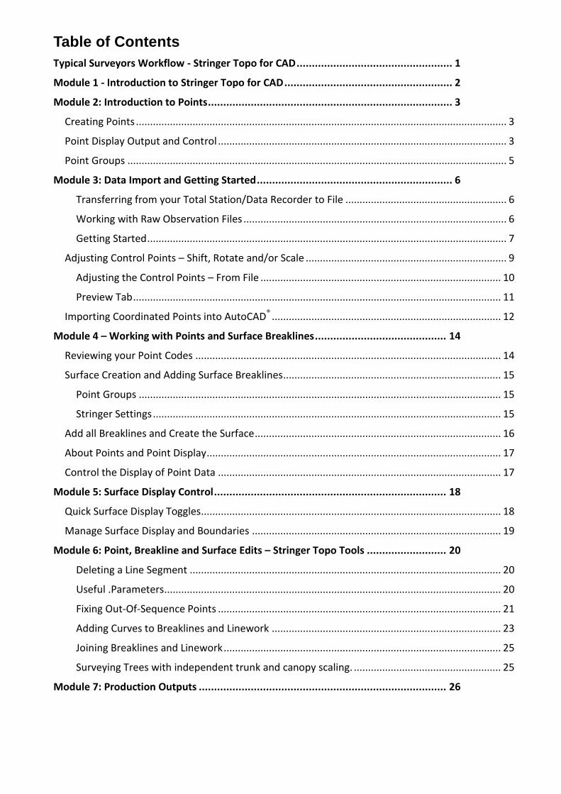
Table of Contents
Typical Surveyors Workflow - Stringer Topo for CAD ................................................... 1
Module 1 - Introduction to Stringer Topo for CAD ....................................................... 2
Module 2: Introduction to Points ................................................................................ 3
Creating Points ................................................................................................................................... 3
Point Display Output and Control ...................................................................................................... 3
Point Groups ...................................................................................................................................... 5
Module 3: Data Import and Getting Started ................................................................ 6
Transferring from your Total Station/Data Recorder to File ......................................................... 6
Working with Raw Observation Files ............................................................................................. 6
Getting Started ............................................................................................................................... 7
Adjusting Control Points – Shift, Rotate and/or Scale ....................................................................... 9
Adjusting the Control Points – From File ..................................................................................... 10
Preview Tab .................................................................................................................................. 11
Importing Coordinated Points into AutoCAD® ................................................................................. 12
Module 4 – Working with Points and Surface Breaklines ........................................... 14
Reviewing your Point Codes ............................................................................................................ 14
Surface Creation and Adding Surface Breaklines ............................................................................. 15
Point Groups ................................................................................................................................ 15
Stringer Settings ........................................................................................................................... 15
Add all Breaklines and Create the Surface ....................................................................................... 16
About Points and Point Display ........................................................................................................ 17
Control the Display of Point Data .................................................................................................... 17
Module 5: Surface Display Control ............................................................................ 18
Quick Surface Display Toggles .......................................................................................................... 18
Manage Surface Display and Boundaries ........................................................................................ 19
Module 6: Point, Breakline and Surface Edits – Stringer Topo Tools .......................... 20
Deleting a Line Segment .............................................................................................................. 20
Useful .Parameters ....................................................................................................................... 20
Fixing Out-Of-Sequence Points .................................................................................................... 21
Adding Curves to Breaklines and Linework ................................................................................. 23
Joining Breaklines and Linework .................................................................................................. 25
Surveying Trees with independent trunk and canopy scaling. .................................................... 25
Module 7: Production Outputs ................................................................................. 26

Page 1 © Copyright – Civil Survey Solutions Pty Ltd
Typical Surveyors Workflow - Stringer Topo for CAD
•The Field survey is based on using Codes related to the Feature being located either by Code only(for a point) or by Code and String Number (for Breakline or stringing things together) Field Survey
•Supports a multitude of Total Stations and field observation file formats
•Travers adjustements can be added to reductions from AutoCAD/csv file Raw Field File
•Edit the RAW data in a user friendly display and save
•Review outputs and co-ordinate reduction
•Import points into the drawng
Stringer Reduction
•COGO points are displayed in the drawing
•Points can be edited and displays can be adjusted
Point Import and Display
•Stringer Settings establish the point display to apply based on point code
•Define if the point is used in the surface
•Define if the point is used for generating 2D linework and/or a breakline Stringer Settings
•Auotmatically creates a surface from the COGO points
•Automatically joins codes with string numbers and adds them to the surface as breaklines
•Automatically draws 2D linework Join All Codes
•Multitude of editing commands to correct/enhance the field survey
•Reorder out of sequence points, search and replace, and more
•Surface updates as changes are applied
Stringer Edit Commands
•Apply surface styles, edit surface display
•Adjust contour intervals and add contour labels
•Turn on the triangles, height shading, slope arrows, etc Surface Outputs
•Generate a Legend table
•Create a points table
Point and Survey Outputs
•Point files can be exported out in many different formats for sharing with customers and for setout. Export points

Page 2 © Copyright – Civil Survey Solutions Pty Ltd
Module 1 - Introduction to Stringer Topo for CAD Stringer Topo provides a comprehensive set of tools for the creation of Topographical Surveys, and includes tools suitable for Cadastral Survey drawings and documentation.
Stringer Topo includes:
- Survey reduction tools, taking the field survey file and enabling editing of survey observations and click button transfer of Cogo Points into the drawing
- Point creation and editing tools, with customisable display incorporating symbols/blocks and text labelling
- Automated point display based on point coding (descriptions) - Point group tools for grouping points and applying to surfaces - Surface (TIN) modelling tools, updating based on edits made to Points and Breaklines.
Surface functionality includes: o Updating directly from edits to survey points and breaklines using Stringer Topo o Creation using drawing data, such as 3D faces, BricsCAD points and 3D polylines o User controllable display for contours, contour labelling, triangles, slope arrows and
height shading - Automated breakline creation, totally customisable by the user and based on user defined
point codes and string numbers. - Extensive breakline editing tools to address any field errors such as:
o Incorrect string numbering o Unrecognised field codes o Out-of-sequence survey pickup of points o Starting/stopping curved breaklines, closing breaklines, and more o Dual coding
- Import and export tools to share data
Page 3 © Copyright – Civil Survey Solutions Pty Ltd
Module 2: Introduction to Points
All COGO points (Points) are created using Stringer Topo commands, and are represented on user definable layers with text and blocks. The total COGO point is contained inside an attributed block, and Stringer Topo includes functionality to easily turn text elements (such as elevation) on/off and to set up text sizes and positions for different elements of text display (eg: point number, elevation and description).
Creating Points
COGO Points can be created manually using the Make Points command, however the most used approach will be to import field survey data into the drawing.
Point Display Output and Control
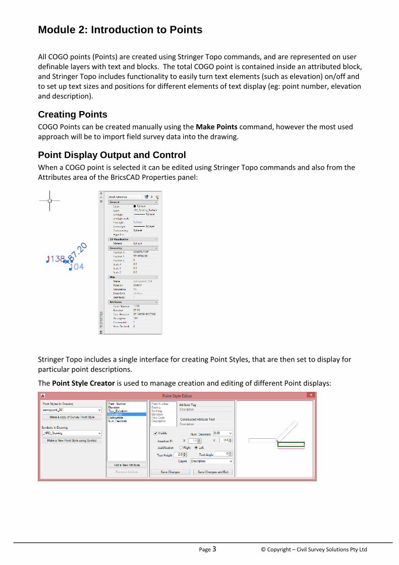
When a COGO point is selected it can be edited using Stringer Topo commands and also from the Attributes area of the BricsCAD Properties panel:
Stringer Topo includes a single interface for creating Point Styles, that are then set to display for particular point descriptions.
The Point Style Creator is used to manage creation and editing of different Point displays:

Page 4 © Copyright – Civil Survey Solutions Pty Ltd
The Stringer Settings form sets up what Point Style to display for different point Codes that you pick up in the field:
This form is significant in automating outputs. It controls:
- Your list of Point Codes that you use in the field - For each point code
o What Point Style to apply o A symbol (optional, since the Point Style can include a symbol also) o The description o The layer to use o The scaling and rotation of the point o Whether the point code is used
For drawing 2d line work For inclusions as a breakline in the surface

Page 5 © Copyright – Civil Survey Solutions Pty Ltd
Point Groups
Point groups provide users the ability to control the points that are used to build a surface, to allow group edits (such as moving, scaling, rotation and datum shift) and for output (such as to a table or as an exported external file).
The Point Group command is used for this purpose:

Page 6 © Copyright – Civil Survey Solutions Pty Ltd
Module 3: Data Import and Getting Started In this example, we will be starting from:
a raw observation file from a Sokkia data recorder (.sdr format), and
a comma delimited (.csv) file containing a list of known control points with co-ordinates. This file will be used to shift, rotate and scale the survey
Transferring from your Total Station/Data Recorder to File
Survey reduction occurs from a raw observation file that has been transferred from the Total Station/Data Recorder to the computer or to a file.
You have access to a wide range of tools to obtain this file, including the use of – Leica Geo Office Tools (for Leica instruments), Prolink (for Sokkia Instruments), Topcon Link (for Topcon instruments) and others. Software often comes with your data recorder to assist in this part of the process.
Working with Raw Observation Files
Stringer Topo includes functionality to read raw observation data from a wide variety of data recorders and typical data file formats. The supported instruments and file formats are routinely updates as required. Currently the following file formats are directly supported:
RW5 (Native format for editing)
NEU (CivilCAD)
FBK (Autodesk)
GSI Code Before/After (Leica)
SDR/RAW (Sokkia)
CRD/RW5 (Sokkia)
RAW C&G
GRE Code Before/After
DN/RAW (Nikon)
FC?/DATA/GT7 (Topcon)
JOB/.ARD/AGA/DC? (Trimble)
CSV file (Comma Delimited)
Once a file is selected the software creates a matching copy of the file and opens it for immediate editing and adjustment of the observations.
Points can be exported from this process and imported directly into BricsCAD®
Page 7 © Copyright – Civil Survey Solutions Pty Ltd
Getting Started
If required, start BricsCAD
From the File menu, select New.
Browse to C:\CSS Training Data\Stringer Topo\For BricsCAD\V18\ and Open the Field Survey Start Drawing.DWG file.
For AutoCAD the path includes “For AutoCAD”.
Go to File > Save As and save the drawing with name Field Survey.dwg.
Note: This drawing contains Point Styles, Point Groups and Layers suitable for the survey data we are importing.
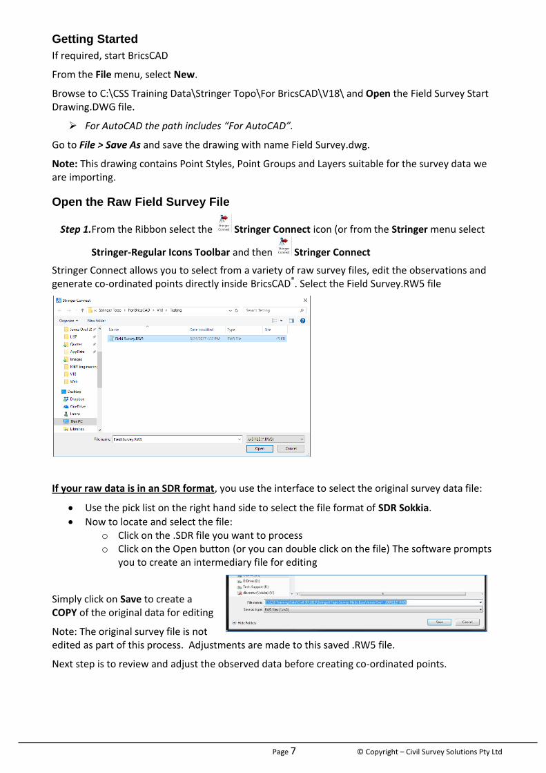
Open the Raw Field Survey File
Step 1.From the Ribbon select the Stringer Connect icon (or from the Stringer menu select
Stringer-Regular Icons Toolbar and then Stringer Connect
Stringer Connect allows you to select from a variety of raw survey files, edit the observations and generate co-ordinated points directly inside BricsCAD®. Select the Field Survey.RW5 file
If your raw data is in an SDR format, you use the interface to select the original survey data file:
Use the pick list on the right hand side to select the file format of SDR Sokkia.
Now to locate and select the file: o Click on the .SDR file you want to process o Click on the Open button (or you can double click on the file) The software prompts
you to create an intermediary file for editing
Simply click on Save to create a COPY of the original data for editing
Note: The original survey file is not edited as part of this process. Adjustments are made to this saved .RW5 file.
Next step is to review and adjust the observed data before creating co-ordinated points.

Page 8 © Copyright – Civil Survey Solutions Pty Ltd
Edit the Observations
The Stringer Connect observations editor immediately opens and includes all your survey data.
Each type of survey data recorded is colour coded for quick and easy identification. You can click on any cell to make direct edits within the cell, or use the dynamic data editing window at the bottom to make any changes to the data row and click Accept.
Use the scroll on the right to review the recorded data or click in the display and use the roller on the mouse.
You can readily move data that has been taken out of sequence and also Add extra data.
Search and Replace tools are available for you to make bulk edits to (usually) the point descriptions (Codes).

Page 9 © Copyright – Civil Survey Solutions Pty Ltd
Adding Observations
It’s easy to add observations in the system by using the Add button..
Removing Observations
Some of the data picked up in the field may be incorrect or no longer needed for inclusion in the output. You can remove it from the co-ordinated points by turning any data row into a Note.
Re-Ordering Observations
Point co-ordinates are calculated by reading and applying the edited observation data working from the top down. You may have taken some shots ‘out of sequence’ or need to otherwise reorder the survey entries – this can easily happen when an Instrument/Target Height adjustment is missed in the field and added later during the field survey.
Adjusting Control Points – Shift, Rotate and/or Scale
It is not uncommon to setup on known control points in the field and to apply assumed co-ordinates and bearings during the field survey. The exact co-ordinates may not be known at the time of the survey or you may wish to adjust these when you are back in the office.
Stringer Topo includes the tools you may require to adjust your control points as part of the import process:
- Inside Stringer Connect: o By typing in the corrected co-ordinates directly in the cells during the reduction
process, or o Importing a file of points (this takes the form of a comma delimited file with
extension .csv) with point numbers matching and adjusted co-ordinates – the software will read in the file and update all the point co-ordinates
o Scaling the co-ordinate points based on imported control points - Using BricsCAD® :
o Graphically move and rotate your control points inside BricsCAD® and update the co-ordinates inside Stringer Connect by reading the updated point co-ordinates from the drawing
o Undertake a traverse adjustment and update the co-ordinates inside Stringer Connect by reading the point co-ordinates from the drawing
In this example we will import a file of known co-ordinates to update the control point co-ordinates inside the editable Field Survey file.
Page 10 © Copyright – Civil Survey Solutions Pty Ltd
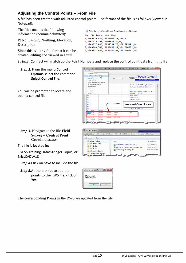
Adjusting the Control Points – From File
A file has been created with adjusted control points. The format of the file is as follows (viewed in Notepad):
The file contains the following
information (comma delimited):
Pt No, Easting, Northing, Elevation,
Description
Since this is a .csv file format it can be
created, editing and viewed in Excel.
Stringer Connect will match up the Point Numbers and replace the control point data from this file.
Step 2. From the menu Control Options select the command Select Control File.
You will be prompted to locate and open a control file
Step 3. Navigate to the file Field
Survey – Control Point
Coordinates.csv.
The file is located in:
C:\CSS Training Data\Stringer Topo\For BricsCAD\V18
Step 4.Click on Save to include the file
Step 5.At the prompt to add the points to the RW5 file, click on Yes
The corresponding Points in the RW5 are updated from the file.
Page 11 © Copyright – Civil Survey Solutions Pty Ltd
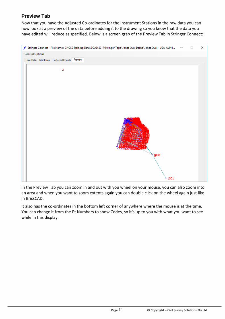
Preview Tab
Now that you have the Adjusted Co-ordinates for the Instrument Stations in the raw data you can now look at a preview of the data before adding it to the drawing so you know that the data you have edited will reduce as specified. Below is a screen grab of the Preview Tab in Stringer Connect:
In the Preview Tab you can zoom in and out with you wheel on your mouse, you can also zoom into an area and when you want to zoom extents again you can double click on the wheel again just like in BricsCAD.
It also has the co-ordinates in the bottom left corner of anywhere where the mouse is at the time. You can change it from the Pt Numbers to show Codes, so it's up to you with what you want to see while in this display.
Page 12 © Copyright – Civil Survey Solutions Pty Ltd
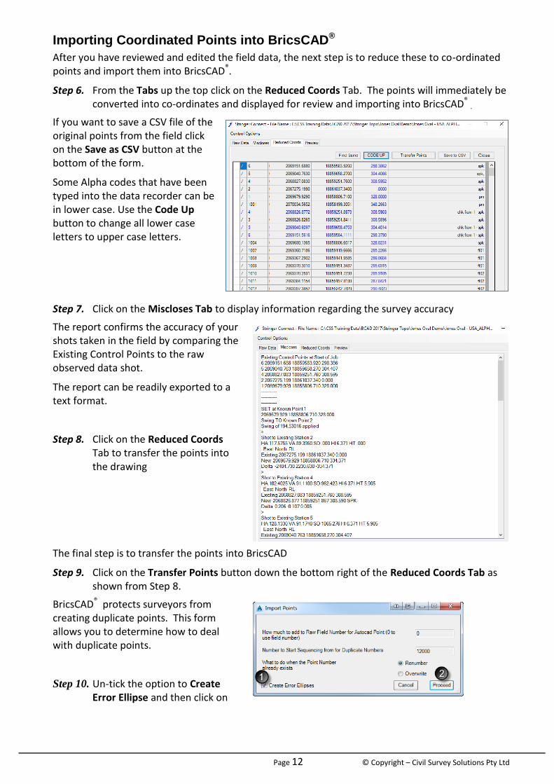
Importing Coordinated Points into BricsCAD®
After you have reviewed and edited the field data, the next step is to reduce these to co-ordinated points and import them into BricsCAD®.
Step 6. From the Tabs up the top click on the Reduced Coords Tab. The points will immediately be converted into co-ordinates and displayed for review and importing into BricsCAD® .
If you want to save a CSV file of the original points from the field click on the Save as CSV button at the bottom of the form.
Some Alpha codes that have been typed into the data recorder can be in lower case. Use the Code Up button to change all lower case letters to upper case letters.
Step 7. Click on the Miscloses Tab to display information regarding the survey accuracy
The report confirms the accuracy of your shots taken in the field by comparing the Existing Control Points to the raw observed data shot.
The report can be readily exported to a text format.
Step 8. Click on the Reduced Coords Tab to transfer the points into the drawing
The final step is to transfer the points into BricsCAD
Step 9. Click on the Transfer Points button down the bottom right of the Reduced Coords Tab as shown from Step 8.
BricsCAD® protects surveyors from creating duplicate points. This form allows you to determine how to deal with duplicate points.
Step 10. Un-tick the option to Create Error Ellipse and then click on

Page 13 © Copyright – Civil Survey Solutions Pty Ltd
Proceed.
If required double click the middle mouse button to zoom to the extents:
All points are now included in the drawing.
Each point has been assigned Point Style based on its description.
You can zoom in and click on any point in the drawing and view the BricsCAD® properties such as point number and elevation.
Note: Stringer has a function called Point Group Commands which will scale a Point Group you have created in the 2d scale only (X,Y not the Z values). These functions are very handy for multiple day jobs.

Page 14 © Copyright – Civil Survey Solutions Pty Ltd
Module 4 – Working with Points and Surface Breaklines With Stringer Topo, you will be prompted to create a surface as soon as you start editing COGO points – Stringer Topo will automatically add points to the surface as well as breaklines. This happens because of the Stringer Settings, which we will discuss in this section.
Reviewing your Point Codes
In a medium to large surveying firm it is important to ensure consistency in the point codes used in the field.
When survey points are imported into BricsCAD® it is important to check that the survey includes all the expected field codes – this can be done by checking all point codes in the drawing to ensure that they match the list of codes specified in the Stringer Settings (which we will discuss later). This check also happens at the time of importing.
Step 11. From the Stringer Ribbon select the Validate Codes command
After a few moments, a validation check is made between the points in the drawing and the Stringer Settings
Point Codes shown right have been used in the field survey but do not have a corresponding code in the Stringer Settings
It is usual to either include these point codes in the Stringer Settings (so the points are put on the correct layer and have the expected display) or else change the Point Code to match one in the Stringer Settings that's already there.
Point Search and Replace
Point code search and replace tools exist in the drawing.
Step 12. To replace all points with description FL with description SWL (swale) select the Search and Replace Dialog (SRD) command from the Stringer Ribbon (or from the Stringer menu select Stringer Point Edit Toolbar and then Search and Replace Dialog)
At the command prompt, press [Enter].
At the Replace Codes form, set the following:
- Code to Replace: FL - Enter New Code: SWL
Click Check ALL PTS.
Click OK when prompted to select points to replace, and then press [Enter] to select all points in the drawing.
All points with description FL are changed to SWL. Any stringing associated with the points will stay the same, just the code is changed. e.g. FL01 - SWL01
Page 15 © Copyright – Civil Survey Solutions Pty Ltd
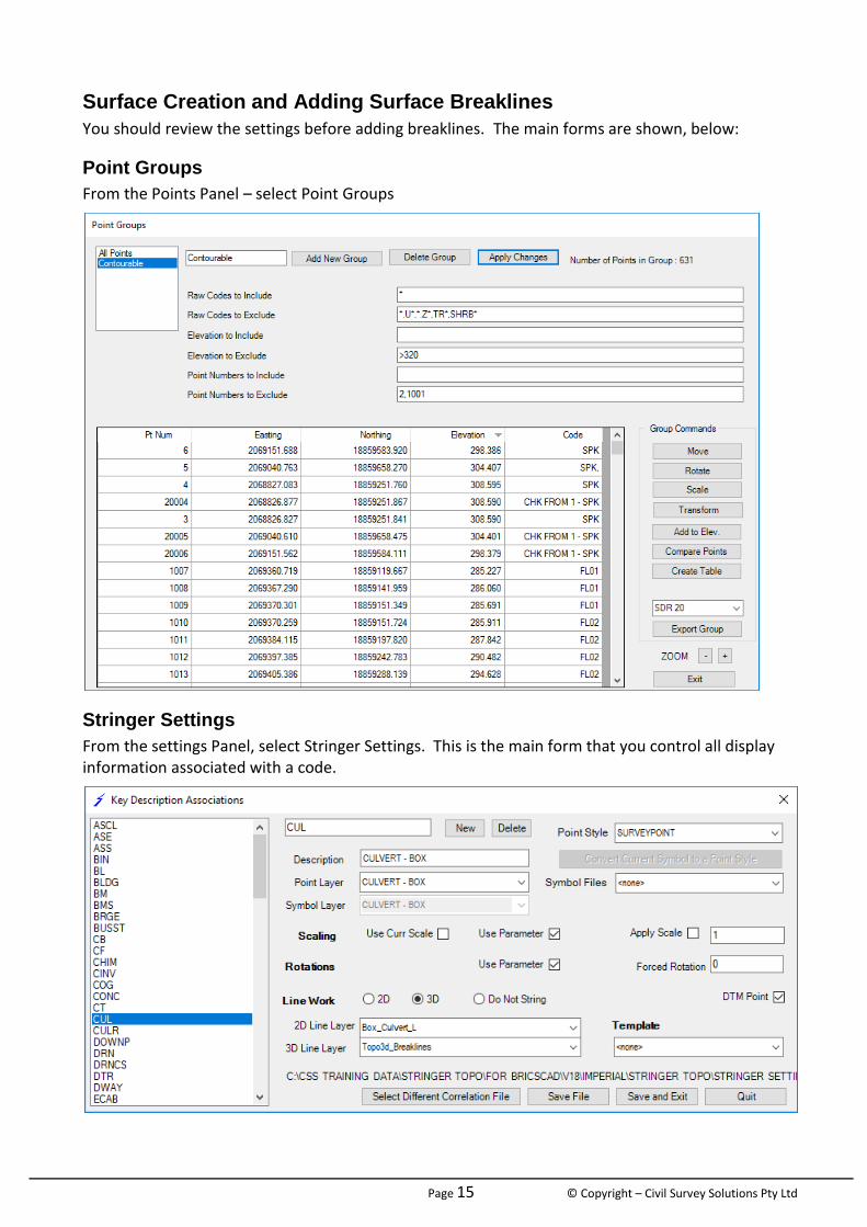
Surface Creation and Adding Surface Breaklines
You should review the settings before adding breaklines. The main forms are shown, below:
Point Groups
From the Points Panel – select Point Groups
Stringer Settings
From the settings Panel, select Stringer Settings. This is the main form that you control all display information associated with a code.
Page 16 © Copyright – Civil Survey Solutions Pty Ltd
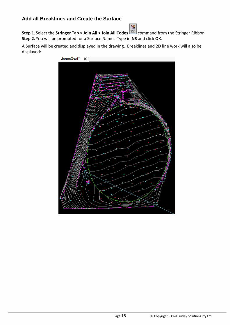
Add all Breaklines and Create the Surface
Step 1. Select the Stringer Tab > Join All > Join All Codes command from the Stringer Ribbon Step 2. You will be prompted for a Surface Name. Type in NS and click OK.
A Surface will be created and displayed in the drawing. Breaklines and 2D line work will also be displayed:
Page 17 © Copyright – Civil Survey Solutions Pty Ltd
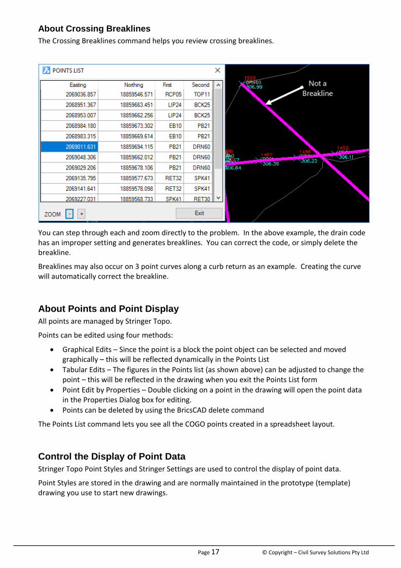
About Crossing Breaklines
The Crossing Breaklines command helps you review crossing breaklines.
You can step through each and zoom directly to the problem. In the above example, the drain code has an improper setting and generates breaklines. You can correct the code, or simply delete the breakline.
Breaklines may also occur on 3 point curves along a curb return as an example. Creating the curve will automatically correct the breakline.
About Points and Point Display
All points are managed by Stringer Topo.
Points can be edited using four methods:
Graphical Edits – Since the point is a block the point object can be selected and moved graphically – this will be reflected dynamically in the Points List
Tabular Edits – The figures in the Points list (as shown above) can be adjusted to change the point – this will be reflected in the drawing when you exit the Points List form
Point Edit by Properties – Double clicking on a point in the drawing will open the point data in the Properties Dialog box for editing.
Points can be deleted by using the BricsCAD delete command
The Points List command lets you see all the COGO points created in a spreadsheet layout.
Control the Display of Point Data
Stringer Topo Point Styles and Stringer Settings are used to control the display of point data.
Point Styles are stored in the drawing and are normally maintained in the prototype (template) drawing you use to start new drawings.
Page 18 © Copyright – Civil Survey Solutions Pty Ltd
Module 5: Surface Display Control As you have seen, COGO points and breaklines created by Stringer Topo will dynamically update the surface.
Stringer Topo creates a dynamic, continuous representation of a surface by connecting the surface points in a network of triangles. The display of surfaces is managed by the Surface Manager – you can set up Surface Styles to automate the presentation of surfaces upon creation and by selecting Style.
You can create as many surfaces as you like, and surfaces can read Drawing Data (eg: 3D faces, 3D polylines, BricsCAD points) to build a surface – this process is described in the Appendix.
You can also make copies of surfaces to raise/lower them, change their display and apply surface Boundaries. Let’s use the Surface you’ve made in the current drawing to show how you can change and manage the surface display.
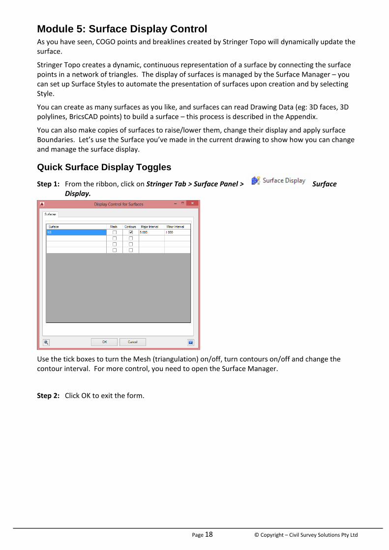
Quick Surface Display Toggles
Step 1: From the ribbon, click on Stringer Tab > Surface Panel > Surface Display.
Use the tick boxes to turn the Mesh (triangulation) on/off, turn contours on/off and change the contour interval. For more control, you need to open the Surface Manager.
Step 2: Click OK to exit the form.
Page 19 © Copyright – Civil Survey Solutions Pty Ltd
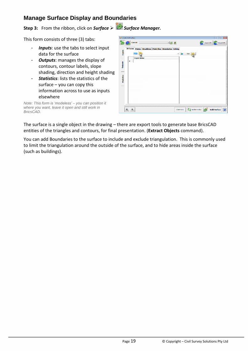
Manage Surface Display and Boundaries
Step 3: From the ribbon, click on Surface Surface Manager.
This form consists of three (3) tabs:
- Inputs: use the tabs to select input data for the surface
- Outputs: manages the display of contours, contour labels, slope shading, direction and height shading
- Statistics: lists the statistics of the surface – you can copy this information across to use as inputs elsewhere
Note: This form is ‘modeless’ – you can position it where you want, leave it open and still work in BricsCAD.
The surface is a single object in the drawing – there are export tools to generate base BricsCAD entities of the triangles and contours, for final presentation. (Extract Objects command).
You can add Boundaries to the surface to include and exclude triangulation. This is commonly used to limit the triangulation around the outside of the surface, and to hide areas inside the surface (such as buildings).
Page 20 © Copyright – Civil Survey Solutions Pty Ltd
Module 6: Point, Breakline and Surface Edits – Stringer Topo Tools Let’s start reviewing the surface triangulation and breaklines. Where issues are identified, we will explore a wide range of tools to quickly make corrections.
Deleting a Line Segment
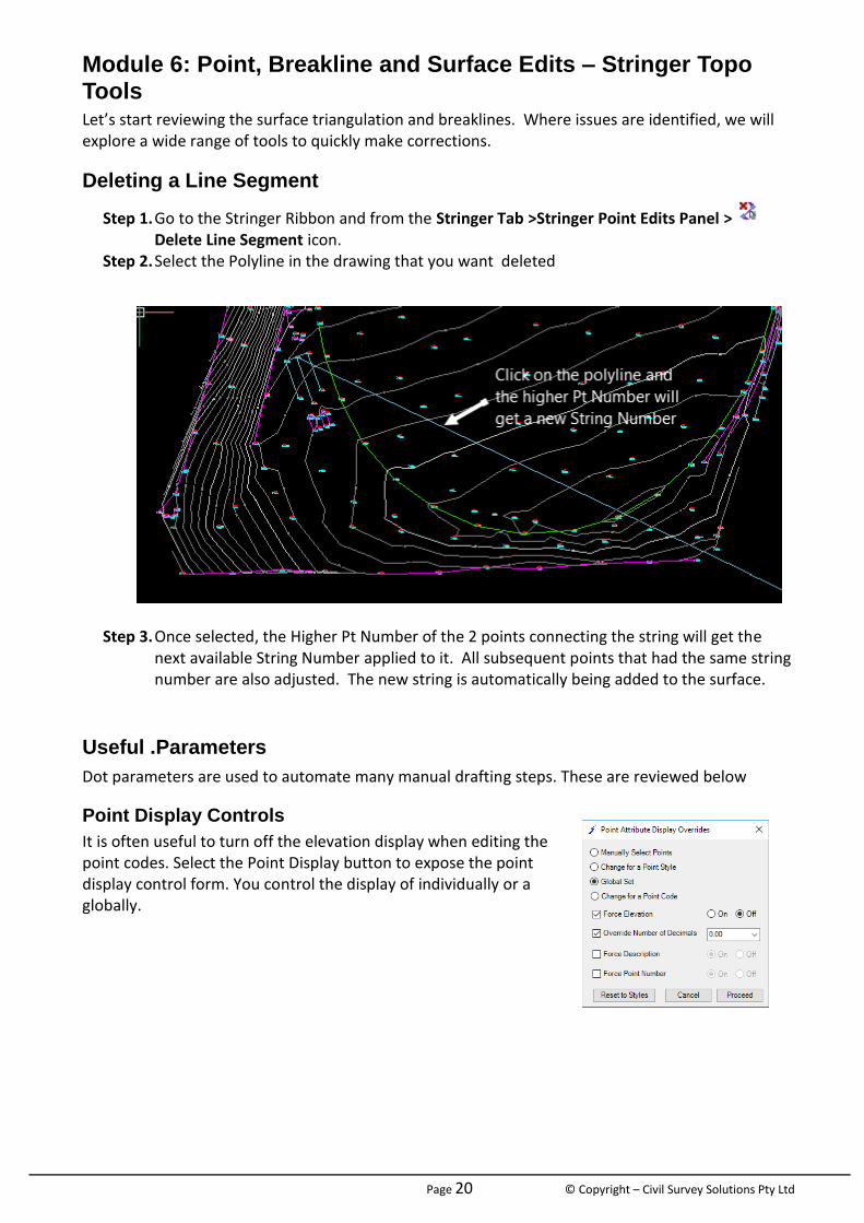
Step 1. Go to the Stringer Ribbon and from the Stringer Tab >Stringer Point Edits Panel > Delete Line Segment icon.
Step 2. Select the Polyline in the drawing that you want deleted
Step 3. Once selected, the Higher Pt Number of the 2 points connecting the string will get the next available String Number applied to it. All subsequent points that had the same string number are also adjusted. The new string is automatically being added to the surface.
Useful .Parameters
Dot parameters are used to automate many manual drafting steps. These are reviewed below
Point Display Controls
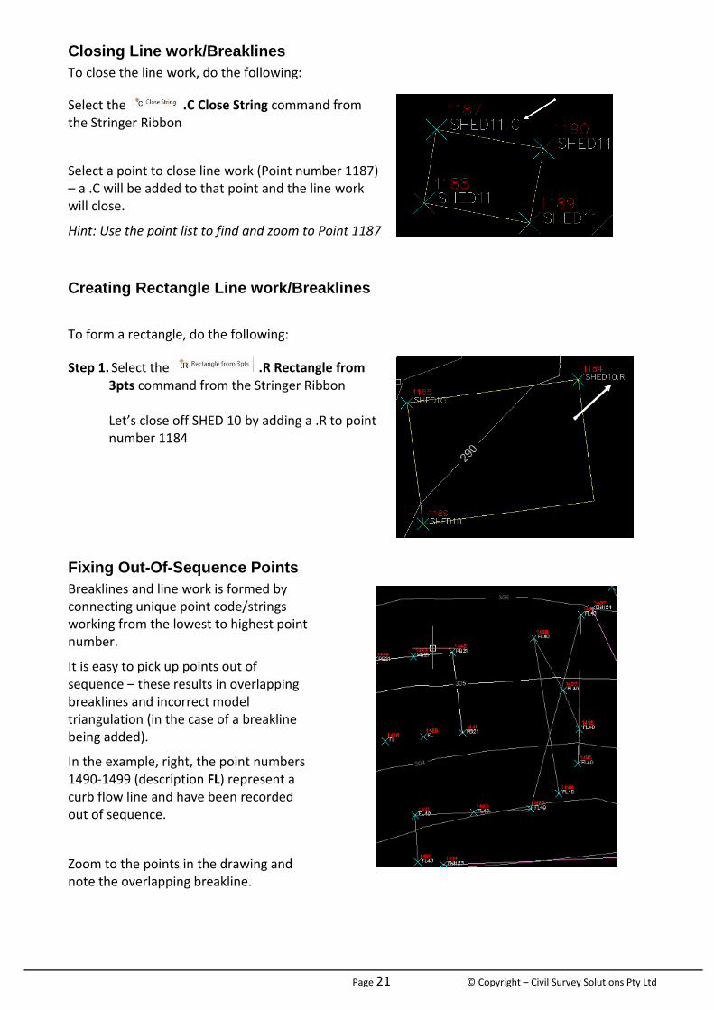
It is often useful to turn off the elevation display when editing the point codes. Select the Point Display button to expose the point display control form. You control the display of individually or a globally.
Page 21 © Copyright – Civil Survey Solutions Pty Ltd
Closing Line work/Breaklines
To close the line work, do the following:
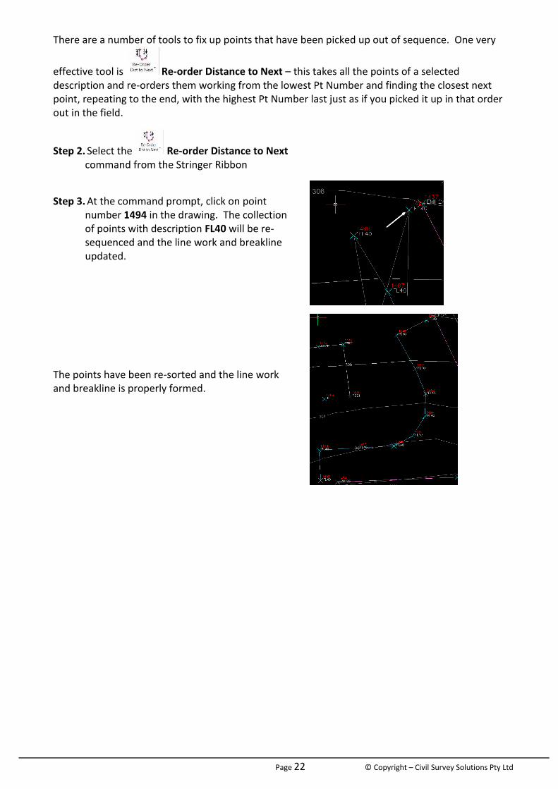
Select the .C Close String command from the Stringer Ribbon
Select a point to close line work (Point number 1187) – a .C will be added to that point and the line work will close.
Hint: Use the point list to find and zoom to Point 1187
Creating Rectangle Line work/Breaklines
To form a rectangle, do the following:
Step 1. Select the .R Rectangle from 3pts command from the Stringer Ribbon Let’s close off SHED 10 by adding a .R to point number 1184
Fixing Out-Of-Sequence Points
Breaklines and line work is formed by connecting unique point code/strings working from the lowest to highest point number.
It is easy to pick up points out of sequence – these results in overlapping breaklines and incorrect model triangulation (in the case of a breakline being added).
In the example, right, the point numbers 1490-1499 (description FL) represent a curb flow line and have been recorded out of sequence.
Zoom to the points in the drawing and note the overlapping breakline.
Page 22 © Copyright – Civil Survey Solutions Pty Ltd
There are a number of tools to fix up points that have been picked up out of sequence. One very
effective tool is Re-order Distance to Next – this takes all the points of a selected description and re-orders them working from the lowest Pt Number and finding the closest next point, repeating to the end, with the highest Pt Number last just as if you picked it up in that order out in the field.
Step 2. Select the Re-order Distance to Next command from the Stringer Ribbon
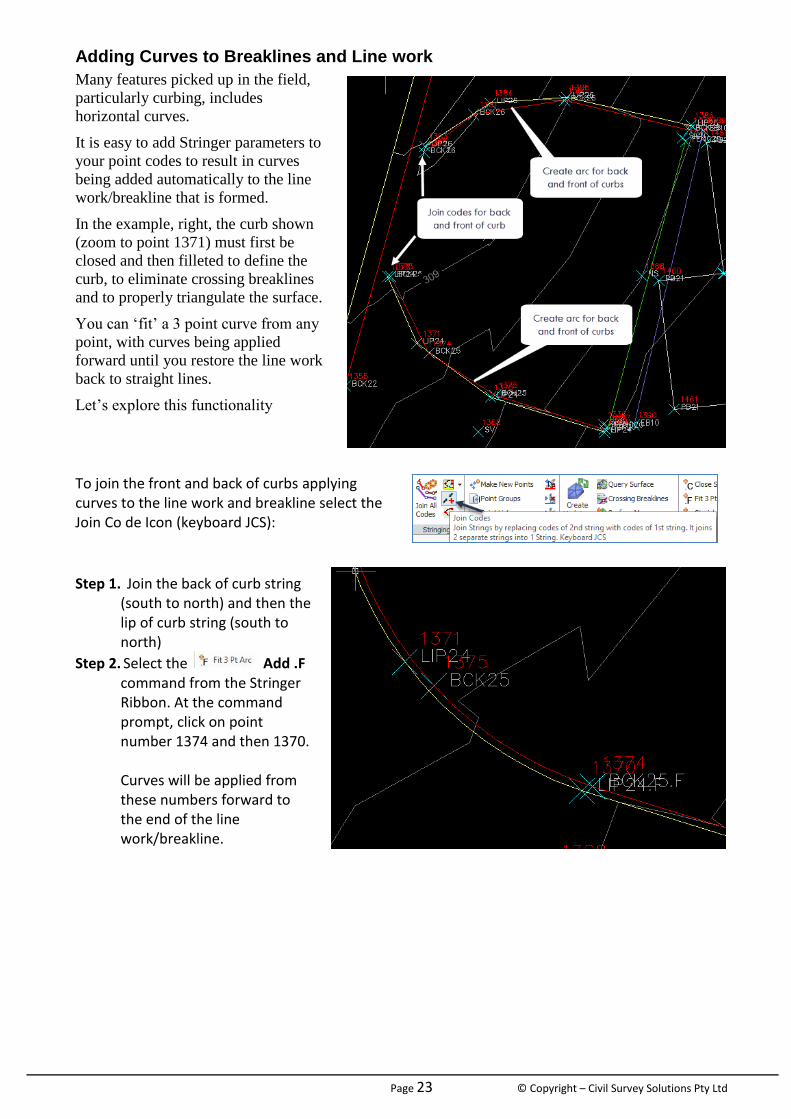
Step 3. At the command prompt, click on point
number 1494 in the drawing. The collection of points with description FL40 will be re-sequenced and the line work and breakline updated.
The points have been re-sorted and the line work and breakline is properly formed.
Page 23 © Copyright – Civil Survey Solutions Pty Ltd
Adding Curves to Breaklines and Line work
Many features picked up in the field,
particularly curbing, includes
horizontal curves.
It is easy to add Stringer parameters to
your point codes to result in curves
being added automatically to the line
work/breakline that is formed.
In the example, right, the curb shown
(zoom to point 1371) must first be
closed and then filleted to define the
curb, to eliminate crossing breaklines
and to properly triangulate the surface.
You can ‘fit’ a 3 point curve from any
point, with curves being applied
forward until you restore the line work
back to straight lines.
Let’s explore this functionality
To join the front and back of curbs applying curves to the line work and breakline select the Join Co de Icon (keyboard JCS):
Step 1. Join the back of curb string (south to north) and then the lip of curb string (south to north)
Step 2. Select the Add .F command from the Stringer Ribbon. At the command prompt, click on point number 1374 and then 1370. Curves will be applied from these numbers forward to the end of the line work/breakline.
Page 24 © Copyright – Civil Survey Solutions Pty Ltd
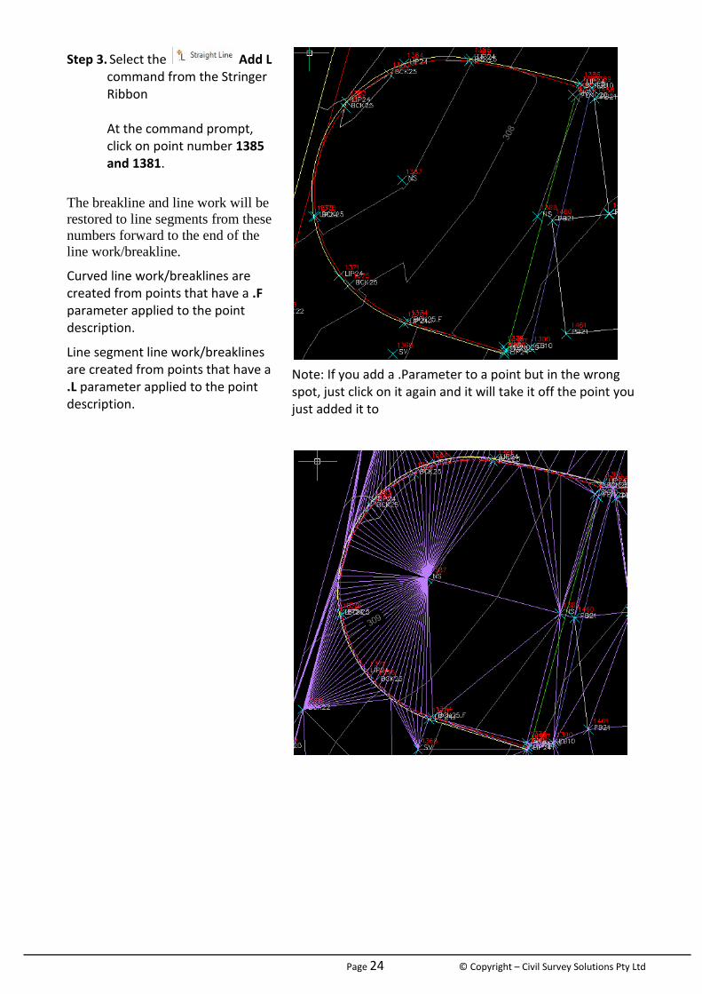
Step 3. Select the Add L command from the Stringer Ribbon At the command prompt, click on point number 1385 and 1381.
The breakline and line work will be
restored to line segments from these
numbers forward to the end of the
line work/breakline.
Curved line work/breaklines are created from points that have a .F parameter applied to the point description.
Line segment line work/breaklines are created from points that have a .L parameter applied to the point description.
Note: If you add a .Parameter to a point but in the wrong spot, just click on it again and it will take it off the point you just added it to
Page 25 © Copyright – Civil Survey Solutions Pty Ltd
Joining Breaklines and Line Work
To make your survey pickup efficient in the field there will be many circumstances when you do not pick up points for a feature in a continuous line – you may start the pickup from either end and work your way to the middle.
This traditionally results in a ‘gap’ in the feature where the different point codes meet. Stringer
Topo includes a number of tools to resolve this type of issue, such as the Join Codes command
Surveying Trees with Independent trunk and canopy scaling.
In AutoCAD® Civil 3D® each point surveyed in the field can have a single symbol assigned to it based on a scaling parameter. Using these tools, surveyors need to make two shots to a tree in order to independently scale the tree trunk and canopy
For many surveyors, it would be preferred to take one shot to a tree and specify the trunk diameter, canopy diameter and height all at once. Stringer facilitates this process by applying multiple BricsCAD® blocks to a point based on its description and the sizing parameters.
The Tree Block Definition command allows you to set the codes that should be used for creation of tree symbols.
You need to have all your tree codes added to this form. This form will then allow you to add the tree block that you want associated with that code to be added as a block in the drawing.
How do we do this? Let’s run through the steps?
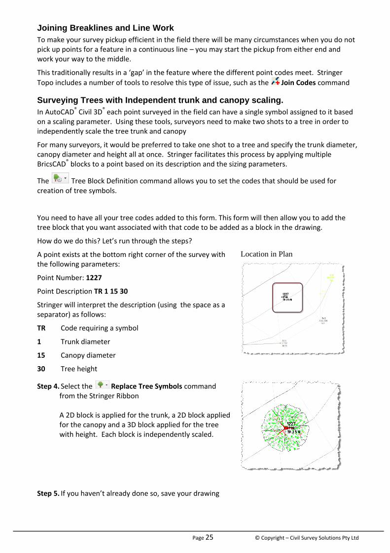
A point exists at the bottom right corner of the survey with the following parameters:
Point Number: 1227
Point Description TR 1 15 30
Stringer will interpret the description (using the space as a separator) as follows:
TR Code requiring a symbol
1 Trunk diameter
15 Canopy diameter
30 Tree height
Location in Plan
Step 4. Select the Replace Tree Symbols command from the Stringer Ribbon A 2D block is applied for the trunk, a 2D block applied for the canopy and a 3D block applied for the tree with height. Each block is independently scaled.
Step 5. If you haven’t already done so, save your drawing
Page 26 © Copyright – Civil Survey Solutions Pty Ltd
Module 7: Production Outputs
Creating a Points Table
To create a Points Table you need to go the Point Groups display and make a point group of what codes you require in the table and click on the Create Table button under the Group commands
A BricsCAD Table can be added to the drawing with the same headings as the PointGroup display.
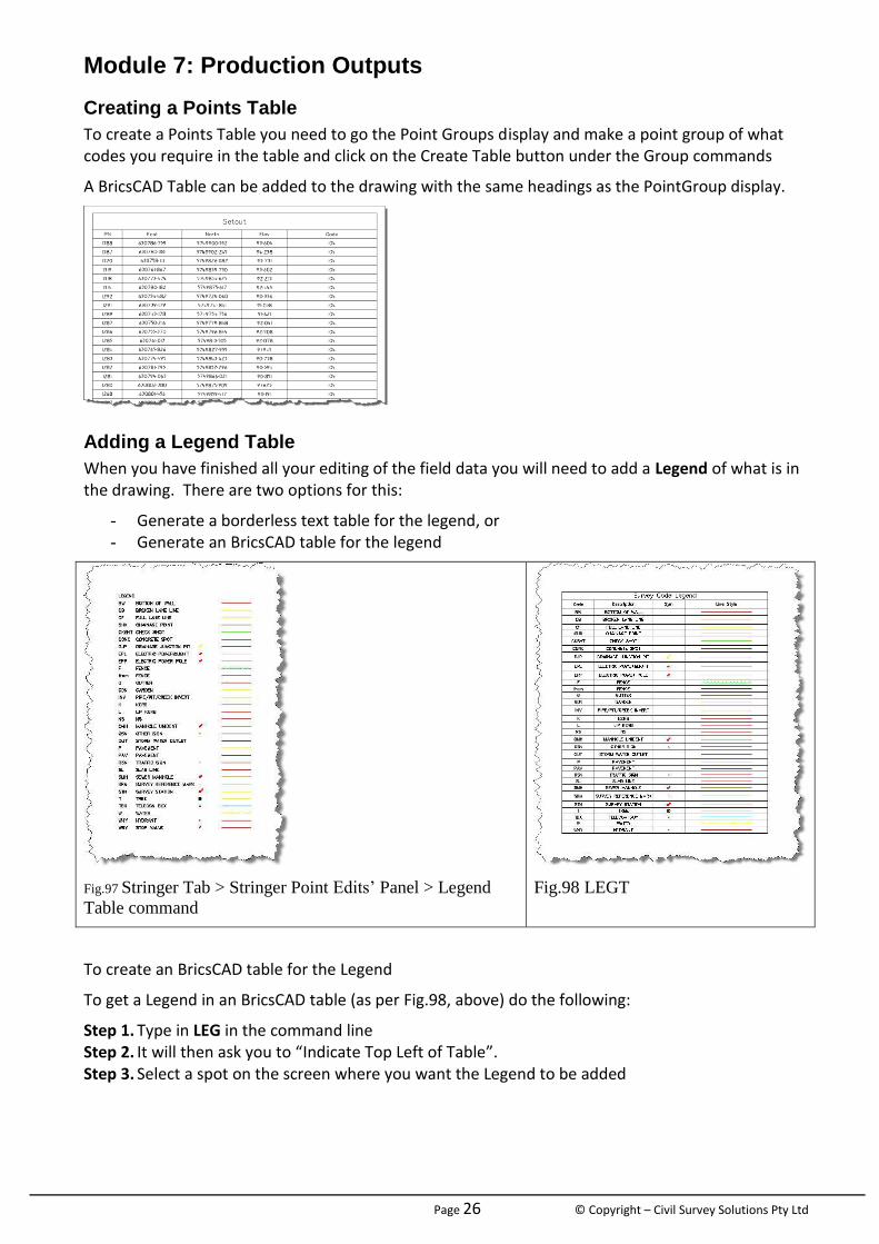
Adding a Legend Table
When you have finished all your editing of the field data you will need to add a Legend of what is in the drawing. There are two options for this:
- Generate a borderless text table for the legend, or - Generate an BricsCAD table for the legend
Fig.97 Stringer Tab > Stringer Point Edits’ Panel > Legend
Table command
Fig.98 LEGT
To create an BricsCAD table for the Legend
To get a Legend in an BricsCAD table (as per Fig.98, above) do the following:
Step 1. Type in LEG in the command line Step 2. It will then ask you to “Indicate Top Left of Table”. Step 3. Select a spot on the screen where you want the Legend to be added

Page 27 © Copyright – Civil Survey Solutions Pty Ltd
Point Exporting
You can use the Point Group command to export coordinated points out to file, using different formats for output.
Surface Display
In the Surface Manager you can export out the contour linework as BricsCAD polylines – this puts in plain BricsCAD entities and doesn’t require Stringer Topo for display.