Embed Size (px)
Citation preview

AASHTOWare BrR 6.8
Truss Tutorial T1 – Truss Floorbeam Stringer Example

T1 – Truss Floorbeam Stringer Example
Last Modified: 8/1/2016 1
6 Spa @ 5'-0" = 30'-0"2'-6" 2'-6"
35'-0"
15'-9" 15'-9"
33'-0"
10" slab
Typical Section
W33x221
(Typ)
Exterior Stringer
W16x57 (Typ)Interior Stringer
W21x57 (Typ)
Elevation
12
'-0"
13
'-0"
14'-0"
6 panels @ 18'-4" = 110'-0"
L0L1 L2 L3 L4 L5 L6
U1
U2U3
U4
U5

T1 – Truss Floorbeam Stringer Example
Last Modified: 8/1/2016 2
CL South Truss
CL North TrussF
B1
FB
2
FB
3
FB
4
FB
5
FB
6
FB
7
S1
S2
S3
S4
S5
S6
S7
Plan View
Truss Live Load Distribution Factors
6'-0"
35'-0"
2'-0"9"
1'-0"
6'-0"4'-0" 2'-0"
Force
1 Lane DF = (31.25 + 25.25)/35 = 1.61 wheels
Multi Lane DF = (31.25 + 25.25 + 19.25 + 13.25)/35 = 2.54 wheels
Deflection
1 Lane DF = 2 wheels/2 trusses = 1.0 wheels
Multi Lane DF = 4 wheels/2 trusses = 2.0 wheels

T1 – Truss Floorbeam Stringer Example
Last Modified: 8/1/2016 3

T1 – Truss Floorbeam Stringer Example
Last Modified: 8/1/2016 4
BrR Training
T1 – Truss Floorbeam Stringer Example
This example describes entering a truss-floorbeam-stringer system and performing a rating of the truss.
Topics covered:
Truss description and analysis
Truss-floorbeam-stringer system superstructure
Truss line superstructures
Note: It is assumed that the user is familiar with BrR and its Bridge Workspace. Therefore, this example does not
go into great detail explaining the Bridge Workspace and detailed entry into windows not particular to a truss.
Truss Description and Analysis
Trusses are described in BrR by entering a text description of the truss in the BrR Truss Command Language. This
command language contains commands to describe the truss geometry, members, loads, etc. The Truss Command
Language User Manual can be accessed from the BrR Truss window’s help topic.
BrR analyzes and rates trusses using the BrR Truss analysis engine. You cannot currently pick an alternate engine
to perform the analysis. The BrR Truss analysis engine analyzes a finite element model of the truss and computes
rating factors using the Load Factor method. The truss is analyzed for axial force only, bending due to load
eccentricity is not considered.
T1 – Truss Floorbeam Stringer Example
Last Modified: 8/1/2016 5
Truss-Floorbeam-Stringer System Superstructure
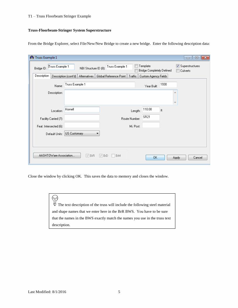
From the Bridge Explorer, select File/New/New Bridge to create a new bridge. Enter the following description data:
Close the window by clicking OK. This saves the data to memory and closes the window.
The text description of the truss will include the following steel material
and shape names that we enter here in the BrR BWS. You have to be sure
that the names in the BWS exactly match the names you use in the truss text
description.

T1 – Truss Floorbeam Stringer Example
Last Modified: 8/1/2016 6
Create the following materials for the bridge:
Save time - copy this
steel from the Library!
Save time - copy the
‘1905 to 1936’ steel from the
Library and just change its
name!

T1 – Truss Floorbeam Stringer Example
Last Modified: 8/1/2016 7
Save time - copy this
concrete from the Library!

T1 – Truss Floorbeam Stringer Example
Last Modified: 8/1/2016 8
Now we need to add steel shapes to our bridge. Open the Steel I Shape window and use the Copy from Library
button to copy the W12x79 to our bridge.
Use the Copy from
Library button!

T1 – Truss Floorbeam Stringer Example
Last Modified: 8/1/2016 9
Follow the same procedure to copy the following steel shapes to our bridge:

T1 – Truss Floorbeam Stringer Example
Last Modified: 8/1/2016 10
The following 2 channel shapes are not in the Standard Library and must be entered manually:

T1 – Truss Floorbeam Stringer Example
Last Modified: 8/1/2016 11

T1 – Truss Floorbeam Stringer Example
Last Modified: 8/1/2016 12
Enter the following Generic appurtenance to model the curb on our structure.

T1 – Truss Floorbeam Stringer Example
Last Modified: 8/1/2016 13
The Bridge Workspace now appears as follows:

T1 – Truss Floorbeam Stringer Example
Last Modified: 8/1/2016 14
We are now ready to create our truss-floorbeam-stringer superstructure definition. Double click on
“SUPERSTRUCTURE DEFINITIONS”.

T1 – Truss Floorbeam Stringer Example
Last Modified: 8/1/2016 15
Enter the following information to describe the superstructure definition:
Stringer Units are the portions of the structure where the stringers are to be analyzed as structurally continuous units.
In this structure, the stringers are simple spans and there are 6 stringer units.
Be sure to select the Main
member configuration as
“Through”. This specifies that live
load is applied to the bottom chord
of the truss.

T1 – Truss Floorbeam Stringer Example
Last Modified: 8/1/2016 16
FB
1
FB
2
FB
3
FB
4
FB
5
FB
6
FB
7
S1
S2
S3
S4
S5
S6
S7
CL North Truss
CL South Truss
Use the ‘Add Default Load Descriptions’ button to create the following load cases:

T1 – Truss Floorbeam Stringer Example
Last Modified: 8/1/2016 17
Enter the truss spacing and stringer spacing as follows:
This structure does not have diaphragms or lateral bracing on the truss members so no data is entered on the
Diaphragms tab.
If we look at the schematic for the framing plan we see that not much is drawn. This is due to the fact that we have
not created our floorbeams yet nor specified where the stringers are.

T1 – Truss Floorbeam Stringer Example
Last Modified: 8/1/2016 18
Enter the following data on the Structure Typical Section to locate the truss and stringers with respect to the left
edge of the deck.
Enter a negative distance to
indicate that the truss is to the left of
the edge of deck.

T1 – Truss Floorbeam Stringer Example
Last Modified: 8/1/2016 19
Enter the remaining structure typical section data as shown below:

T1 – Truss Floorbeam Stringer Example
Last Modified: 8/1/2016 20
The Structure Typical Section now appears as follows:

T1 – Truss Floorbeam Stringer Example
Last Modified: 8/1/2016 21
Open the Floorbeam Member Locations window and use the ‘Floorbeam LocationWizard’ button to specify where
the floorbeams are located.

T1 – Truss Floorbeam Stringer Example
Last Modified: 8/1/2016 22
The following floorbeam member locations are created using the wizard.

T1 – Truss Floorbeam Stringer Example
Last Modified: 8/1/2016 23
Enter the following data to describe the Stringer Group Definition. A stringer group definition contains data
regarding a portion of the structure where the stringers are structurally continuous. The stringers in this structure all
have the same span data. They are simple spans and are supported by 2 floorbeams. You can create one stringer
group definition to contain this geometry data and then later apply this stringer group definition to all 6 stringer units
in your structure.

T1 – Truss Floorbeam Stringer Example
Last Modified: 8/1/2016 24
Describing a Floorbeam Definition:
Create a new floorbeam definition and describe it as follows. This floorbeam definition will be used for all of the
floorbeams in the structure.

T1 – Truss Floorbeam Stringer Example
Last Modified: 8/1/2016 25
Describe the floorbeam profile as follows. The floorbeam is non-composite so we do not have to enter any data on
the Deck Profile window.

T1 – Truss Floorbeam Stringer Example
Last Modified: 8/1/2016 26
Describing a Stringer Definition:
Create a new stringer definition and describe it as follows.
Save time – associate the
stringer span lengths with the
stringer group definition!

T1 – Truss Floorbeam Stringer Example
Last Modified: 8/1/2016 27
Describe the stringer profile as follows. The stringer is non-composite so we do not have to enter any data on the
Deck Profile window.

T1 – Truss Floorbeam Stringer Example
Last Modified: 8/1/2016 28
Create a stringer definition to be used for the exterior stringers in the same manner.
Save time – associate the
stringer span lengths with the
stringer group definition!

T1 – Truss Floorbeam Stringer Example
Last Modified: 8/1/2016 29

T1 – Truss Floorbeam Stringer Example
Last Modified: 8/1/2016 30
The Bridge Workspace tree now appears as follows:

T1 – Truss Floorbeam Stringer Example
Last Modified: 8/1/2016 31
Open the ‘Truss 1’ window and change the name of the truss to “North Truss’. Enter the text description shown on
the next pages.
The ‘Verify’ button will read your text description of the truss and verify the syntax of the commands you have
input.

T1 – Truss Floorbeam Stringer Example
Last Modified: 8/1/2016 32
The following is a copy of the truss definition described using the BrR Truss Command Language. A description of
the command language and its syntax is available by opening the BrR help for the Truss window.
Some of the commands are described in detail below. The name of the command is shown in bold text.
Command Comments
Truss "North Truss"
Unit
Force kips
Length ft
Properties in
DefaultSysUnitType US
DefaultStructSteel "Truss Steel" The steel material ‘Truss Steel’ from the BrR BWS
will be used as the default steel material if you do
not enter a steel material in later commands. The
double quotations around “Truss Steel” indicate that
Truss Steel is defined in the BrR BWS.
DefaultEndConnection
Bolted
Used to determine the effective length factor K
MaterialType
Steel = "Truss Steel"
Steel2 = "Grade 36"
Wherever ‘Steel’ appears in later commands, the
properties from the ‘Truss Steel’ in the BWS will be
used.
This command is a shortcut way to specify a steel
material. This is useful for some of the steel
materials in the BrR Library whose names are
lengthy.
MemberCrossSection
ChannelBox = Section1
Channels "C 15x55" Outward 13.0
Lacing Top

T1 – Truss Floorbeam Stringer Example
Last Modified: 8/1/2016 33
NonDetailed = Section2
47.51 44.50 Steel 1125.6
Entered as a NonDetailed section instead of
describing each plate. We only have to enter the
gross, net area and moment of inertia of the section
in this command.
Rolled = Section3
Beam "W 12x79"
ChannelBox = Section4
TopFlangePlate
22.0 0.5 Steel2
Channels "C 15x50" Outward 13.0
Lacing Bottom
The top cover plate uses ‘Steel2’ instead of the
default steel.
ChannelBox = Section5
TopFlangePlate
22.0 0.5
LeftWebPlate
12.0 0.375
RightWebPlate
12.0 0.375
Channels "C 15x45" Outward 13.0
Connection Bolted 1.50
Lacing Bottom
1.50 in2 will be deducted from the gross area for the
connection holes.

T1 – Truss Floorbeam Stringer Example
Last Modified: 8/1/2016 34
Rolled = Section6
Beam “W 12x65”
PanelPoint
L0 Lower 0.0000 0.0
L1 Lower 18.3333 0.0
L2 Lower 36.6667 0.0
L3 Lower 55.0000 0.0
L4 Lower 73.3333 0.0
L5 Lower 91.6667 0.0
L6 Lower 110.0000 0.0
U1 Upper 18.3333 12.0
U2 Upper 36.6667 13.0
U3 Upper 55.0000 14.0
U4 Upper 73.3333 13.0
U5 Upper 91.6667 12.0
Member
L0L1 L0 L1 Section1
L1L2 L1 L2 Section1
L2L3 L2 L3 Section2
L3L4 L3 L4 Section2
L4L5 L4 L5 Section2
L5L6 L5 L6 Section2
L0U1 L0 U1 Section4
U1U2 U1 U2 Section5
U2U3 U2 U3 Section5
U3U4 U3 U4 Section5
U4U5 U4 U5 Section5
U5L6 U5 L6 Section4
L1U1 L1 U1 Section3
U1L2 U1 L2 Section6
L2U2 L2 U2 Section3
L2U3 L2 U3 Section6
L3U3 L3 U3 Section3
Members are identified by the panel points that they
connect and cross sections are assigned to the
members in this command.

T1 – Truss Floorbeam Stringer Example
Last Modified: 8/1/2016 35
U3L4 U3 L4 Section6
L4U4 L4 U4 Section3
L4U5 L4 U5 Section6
L5U5 L5 U5 Section3
Support
L0 Pinned
L6 Roller
LLDistribution
OneLane 0.805 0.5
MultiLane 1.27 1.0
Lane distribution factors
A schematic of the truss is available by selecting the ‘View schematic’ toolbar button when the truss is highlighted
in the Bridge Workspace tree.

T1 – Truss Floorbeam Stringer Example
Last Modified: 8/1/2016 36
We can now finish describing the floor system (floorbeams and stringers) for this structure. If the floorbeams and
stringers are described, BrR will be able to compute the dead load of the floor system and apply it to the truss during
the truss analysis.
When we first open this Floor System Geometry window, we know the total number of stringer members in this
structure is 42 since there are 6 stringer units and each unit contains 7 stringers. We don’t know where the stringer
members are located along the length of the structure nor do we know how long each stringer is. The stringer
members in the structure are all located at the beginning of the structure and do not have any length to them until a
stringer group definition is assigned to the stringer units. The stringer group definition defines the stringer span
lengths. Assigning stringer group definitions to the stringer units also locates the stringer members along the length
of the structure. Click F1 while this window is open to view examples illustrating how to assign stringer group
definitions to stringer units.

T1 – Truss Floorbeam Stringer Example
Last Modified: 8/1/2016 37
Click on STRINGER UNIT LAYOUT then click on the following button
Use the Stringer Member Alternative wizard to create Stringer Member Alternatives.

T1 – Truss Floorbeam Stringer Example
Last Modified: 8/1/2016 38

T1 – Truss Floorbeam Stringer Example
Last Modified: 8/1/2016 39
Select each stringer and use the Compute from Typical Section button to compute the stringer live load distribution
factors.

T1 – Truss Floorbeam Stringer Example
Last Modified: 8/1/2016 40

T1 – Truss Floorbeam Stringer Example
Last Modified: 8/1/2016 41
Now use the Floorbeam Member Alternative Wizard to create floorbeam member alternatives.
The Framing Plan Schematic now appears as follows:
T1 – Truss Floorbeam Stringer Example
Last Modified: 8/1/2016 42
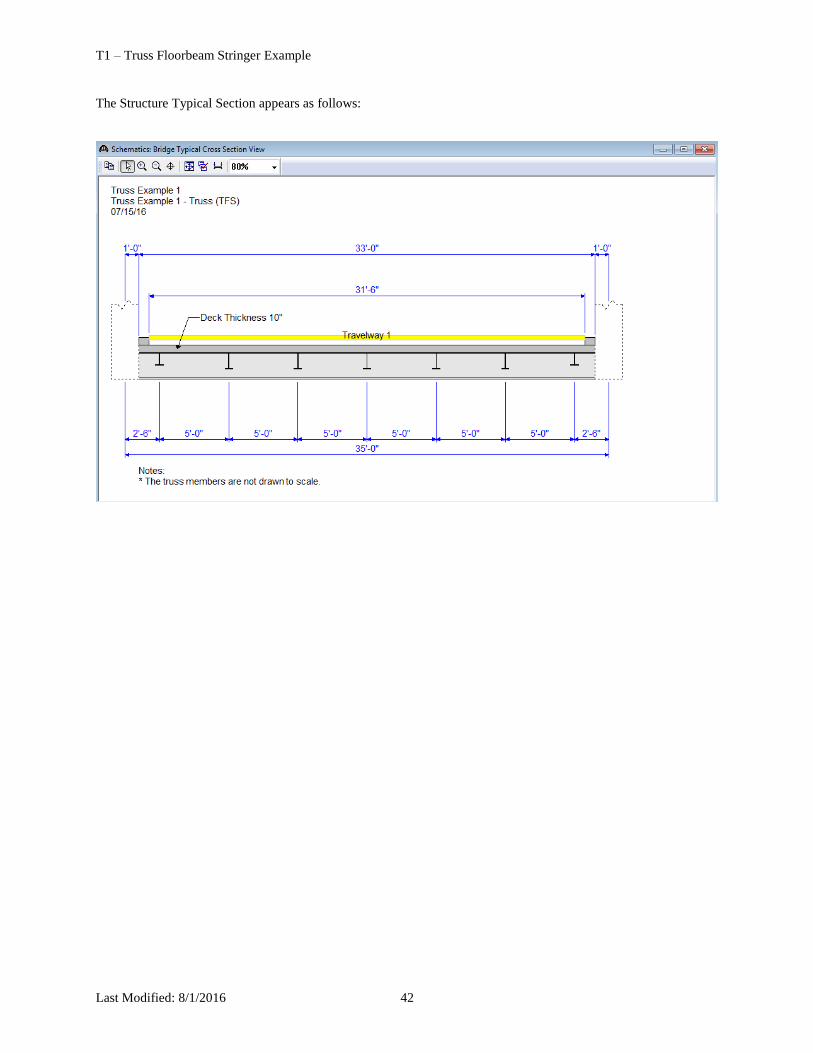
The Structure Typical Section appears as follows:

T1 – Truss Floorbeam Stringer Example
Last Modified: 8/1/2016 43
Select the HS 20 vehicle for the analysis.

T1 – Truss Floorbeam Stringer Example
Last Modified: 8/1/2016 44
Select the ‘North Truss’ in the BWS tree and select the ‘Analyze’ toolbar button to analyze the truss. An analysis
progress dialog will appear with messages related to the analysis. After the analysis you can view the output files by
selecting the ‘View latest analysis output’ toolbar button.
The ‘Live Load Analysis Detail’ and ‘Live Load Analysis Summary’ files contain data related to the live loading of
the truss influence lines. The ‘FE Model for DeadLoad Analysis’ report contains the truss finite element model and
dead load analysis. The ‘Section Property Report” contains data related to the computed and user input truss
member section properties. The ‘Rating Results’ file contains the rating results for the truss. The ‘Log file’ is the
analysis log produced when the analysis is run. This file may contain errors and warnings that should be reviewed.

T1 – Truss Floorbeam Stringer Example
Last Modified: 8/1/2016 45
A portion of the Rating Results output report is shown below.

T1 – Truss Floorbeam Stringer Example
Last Modified: 8/1/2016 46
Truss Line Superstructures
The Bridge Workspace tree for a truss-floorbeam-stringer line superstructure definition is shown below.
In a truss line superstructure definition, the relationship between the truss and floor system is not defined.
Therefore, you must enter the floor system dead loads that act on the truss yourself. These loads are computed as
follows:
Deck Dead Load on Truss
Deck DL = 10”/12 * 33.0’ * 0.150pcf = 4.125 kip/ft
L0, L6: 18.33’/2 * 4.125 k/ft / 2 trusses = 18.90 kips
L1, L2, L3, L4, L5: 18.33’ * 4.125 k/ft / 2 trusses = 37.81 kips
Curb Dead Load on Truss
Curb DL = 85 lb/ft
L0, L6: 18.33’/2 * 0.085 k/ft * 2 curbs / 2 trusses = 0.78 kips
L1, L2, L3, L4, L5: 18.33’ * 0.085 k/ft * 2 curbs / 2 trusses = 1.56 kips
Floorbeam Dead Load on Truss
Floorbeam DL = 221 lb/ft*35 ft = 7735 lb

T1 – Truss Floorbeam Stringer Example
Last Modified: 8/1/2016 47
L0, L1, L2, L3, L4, L5, L6: 7.735 kips / 2 trusses = 3.87 kips
Stringer Dead Load on Truss
Exterior Stringer DL = 57 lb/ft
Interior Stringer DL = 57 lb/ft
L0, L6: 7 stringers * 0.057 kip/ft * 18.33’/2 / 2 trusses = 1.83 kips
L1, L2, L3, L4, L5: 7 stringers * 0.057 kip/ft * 18.33’ / 2 trusses = 3.66 kips
The truss command language description for the truss line is the same as the description for the truss system with the
addition of a command to describe the user computed floor system dead loads. The following is the PanelPointLoad
command used to describe the floor system dead load acting on the truss. This command comes after the Support
command.
PanelPointLoad
L0 DC 0.0 -25.38
L1 DC 0.0 -46.90
L2 DC 0.0 -46.90
L3 DC 0.0 -46.90
L4 DC 0.0 -46.90
L5 DC 0.0 -46.90
L6 DC 0.0 -25.38