Embed Size (px)
Citation preview
1© 2008 Schneider Electric. All rights reserved.
Doc# 3000DB0810R6/08 6/08
LaVergne, TN, USA
Square D Preferred Methods for Arc-Flash Incident Energy ReductionReducing arc-flash incident energy (AFIE) levels has become an increasingly important consideration in designing electrical power systems. However, selective coordination of overcurrent protective devices is equally important and both are often misunderstood. The best solution is to provide superior AFIE reduction without sacrificing selectivity.
Square D® Masterpact® low-voltage power circuit breakers (LVPCBs) offer increased arc-flash protection thanks to faster clearing times, especially at higher current levels. In addition to superior arc-flash protection inherent in their design, Masterpact® breakers can be configured in a variety of “Zone Selective Interlocking” (ZSI) schemes to further enhance protection with no impact on selectivity. Likewise, SepamTM overcurrent relays can also be applied in ZSI solutions.
In some cases, simply taking the time to obtain accurate equipment data may allow improved AFIE results without sacrificing selectivity.
In an attempt to respond to the benefits afforded by these successful Square D products, some manufacturers have introduced alternate schemes which reduce AFIE levels by temporarily compromising selective coordination. It is imperative that consultants and end users understand the risks introduced by these compromise schemes as well as the technical considerations that must be addressed.
An Arc-Flash Hazard Analysis must be performed on the system and the associated equipment. The AFIE reduction methods are of no use unless the AFIE levels and protection requirements are known and defined in the analysis.
This bulletin describes Square D preferred methods for AFIE reduction that do not involve compromises to selective coordination. Alternative approaches are also presented, as well as their associated risks and technical issues so that consultants and end users can make informed decisions.
INTRODUCTION
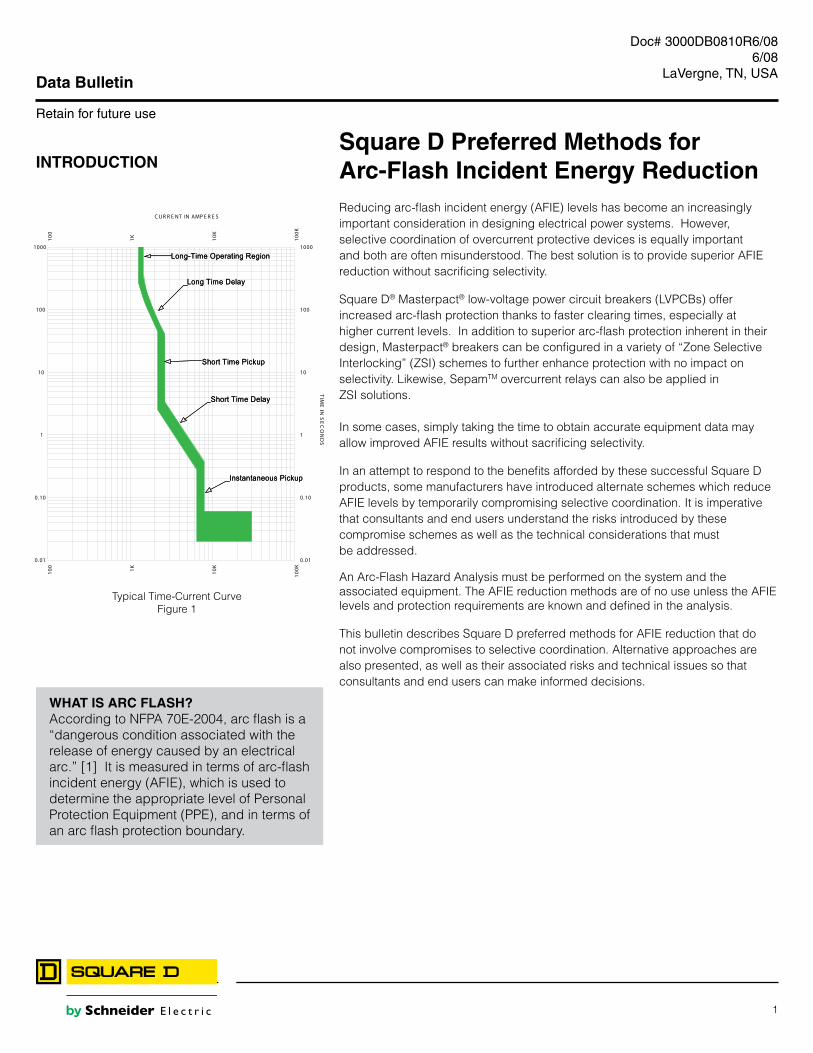
WHAT IS ARC FLASH?According to NFPA 70E-2004, arc flash is a “dangerous condition associated with the release of energy caused by an electrical arc.” [1] It is measured in terms of arc-flash incident energy (AFIE), which is used to determine the appropriate level of Personal Protection Equipment (PPE), and in terms of an arc flash protection boundary.
Data Bulletin
Retain for future use
100
100
1K1K
10K
10K
100K
100K
0 .01 0.01
0.10 0.10
1 1
10 10
100 100
1000 1000
C UR R E NT IN AMP E R E S
TIM
E IN
SE
CO
ND
S
Long-Time Operating Region
Long Time Delay
Short Time Pickup
Short Time Delay
Instantaneous Pickup
Long-Time Operating Region
Long Time Delay
Short Time Pickup
Short Time Delay
Instantaneous Pickup
Typical Time-Current CurveFigure 1

2 © 2008 Schneider Electric. All rights reserved.
Doc# 3000DB0810R6/08 06/08LaVergne, TN, USA
ARC-FLASH INCIDENT ENERGY The incident energy associated with an arc is defined as “the amount of energy impressed on a surface, a certain distance from the source, generated during an electrical arc event.” [2] NFPA 70E-2004 defines several “Hazard/Risk Categories” and the prescribed PPE for each, as shown in the table below. The amount of energy is directly proportional to the magnitude of current and its duration. Because the arc duration is controllable, it is often the focus of arc flash reduction techniques. [4]
Typical Protective Clothing Systems
Hazard Risk Category Clothing Description (Typical number of clothing layers is given in parentheses)
Required Minimum Arc Rating of PPE [J/cm2(cal/cm2)]
0 Non-melting, flammable materials (i.e., untreated cotton, wool, rayon or silk, or blends of these materials) with a fabric weight at least 4.5 oz/yd2 (1)
N/A
1 FR shirt and FR pants or FR coverall (1) 16.74 (4)
2 Cotton underwear – conventional short sleeve and brief/shorts, plus FR shirt and FR pants (1 or 2)
33.47 (8)
3 Cotton underwear plus FR shirt and FR pants plus FR coverall, or cotton under-wear plus two FR coveralls (2 or 3)
104.6 (25)
4 Cotton underwear plus FR shirt and FR pants plus multilayer flash suit (3 or more)
167.36 (40)
NFPA 70E - 2004
Arc Flash InformationCategory
0Use this information in accordancewith applicable OSHA standards,
NFPA 70E, and other required safeelectrical work practices.
25 inches Flash Protection Boundary
2 cal/cm2 Max Incident Energy at 18” Working Distance
Category 0 PPE Category (Per NFPA 70E-2004)
208 VAC Shock hazard when cover is open
42 inches Limited Approach
Avoid Contact Restricted Approach
Avoid Contact Prohibited ApproachPer NFPA 70E-2004
Values produced by a Square D® Engineering Services analysis.Any system modification, adjustment of protective device settings,or failure to properly maintain equipment will invalidate this label.
For more information, contact Square D Engineering at 1-888-SQUARED.
Copyright©2007 Schneider Electric All Rights Reserved
Q2C: 12345678
Date: 12/26/07
}
Square D Arc Flash LabelFigure 3
Table 130.7(C)(11) Protective Clothing Characteristics Figure 2

3© 2008 Schneider Electric. All rights reserved.
Doc# 3000DB0810R6/08 6/08
LaVergne, TN, USA
The objective of a short-circuit/time current coordination (SC/TCC) study is to determine the fastest practical time-current characteristic for each protective device while carrying full load and momentary inrush currents and maintaining selective coordination with upstream and downstream protective devices. [5] For example, in order to ensure selective coordination between a main breaker and the largest feeder, the main breaker’s short time delay function is set one step higher than the feeder’s. That is, a brief intentional delay is introduced for the main breaker in order to allow the feeder breaker time to clear the fault. In this way, the main breaker will not trip unless a) the feeder does not clear the fault or b) the fault is ahead of the feeder breaker (e.g., on the main bus between the feeder and the main).
However, real-world pressures on schedules and budgets often affect time-current coordination results, with an inadvertent impact on arc flash levels. Equipment designs may be finalized long before power system designers have the opportunity to make recommendations. Inadequate attention to data collection may provide system designers without sufficient information on upstream and downstream equipment and loading. Forced to make assumptions, designers may opt for time-current settings higher than needed, just to avoid any possibility of nuisance trips and interruptions to operations. These higher settings sometimes result in higher arc flash levels.
Consider the example below. Given more accurate information about combined inrush current from motors and transformers, it may be possible to reduce the main breaker’s short time pickup and delay settings without sacrificing selective coordination. (Figure 5b)
ENSURING OPTIMAL TIME-CURRENT CHARACTERISTICS
TypicalFigure 5a
OptimalFigure 5b
Example System One-LineFigure 4
100
100
1K1K
10K
10K
100K
100K
1M1M
0.01 0.01
0.10 0.10
1 1
10 10
100 100
1000 1000
TIME
IN S
EC
ON
DS
PRIMARY FUSE
TRANSFORMER
MAIN CB
CB F1
PRIMARY FUSE
TRANSFORMER
MAIN CB
CB F1
CURRENT IN AMPERES
Ref. Voltage: 480V Current Scale x X 10^0
100
100
1K1K
10K
10K
100K
100K
1M1M
0.01 0.01
0.10 0.10
1 1
10 10
100 100
1000 1000
CURRENT IN AMPERES
TIME
IN S
EC
ON
DS
PRIMARY FUSE
TRANSFORMER
MAIN CB
CB F1
PRIMARY FUSE
TRANSFORMER
MAIN CB
CB F1
Ref. Voltage: 480V Current Scale x X 10^0
UTILITY SOURCE13.8kV
PRIMARY FUSE200E
TRANSFORMER3000 kVA13.8kV:480Y/277V5.75%Z
MAIN CBELECTRONIC TRIP LSIG4000A/3P
CB F1ELECTRONIC TRIP LSIG2000A/3P
CB F2ELECTRONIC TRIP LSIG1600A/3P
CB F3ELECTRONICTRIP LSIG800A/3P
MAIN SWITCHGEAR

4 © 2008 Schneider Electric. All rights reserved.
Doc# 3000DB0810R6/08 06/08LaVergne, TN, USA
AFIE PERMANENT REDUCTION METHODS Zone Selective Interlocking
Zone selective interlocking preserves the desired selective coordination between main, tie and feeder protective devices but also allows fast tripping for faults within each device’s desired zone. This is accomplished via wired connections between trip units or relays. If a feeder detects an overcurrent condition it sends a restraining signal to upstream breaker(s). The main (and tie) then follows its normal time-current characteristics and serves as a backup. However, if the main breaker detects an overcurrent condition above its short time (or ground fault) pickup setting, but the feeders do not (e.g., main bus fault), then the main breaker will not receive a restraint signal and it will trip with no intentional time delay. (See figure 6) In this way, ZSI offers the “best of both worlds” – fast clearing of fault currents without sacrificing selective coordination. Furthermore, ZSI is available on both low-voltage and medium-voltage equipment, and can be applied for both phase faults and ground fault protection. Like Masterpact arc-flash circuit breakers, this solution is available for both new construction (Square D® power equipment) and retrofit of existing.
Main breaker trips on short time delay for faults on load side of feeders (restraint signal)
Main breaker trips with no intentional delay for bus faults
x=fault
UTILITY SOURCE13.8kV
PRIMARY FUSE200E
TRANSFORMER3000 kVA13.8kV:480Y/277V5.75%Z
MAIN CBELECTRONIC TRIP LSIG4000A/3P
CB F1ELECTRONIC TRIP LSIG2000A/3P
CB F2ELECTRONIC TRIP LSIG1600A/3P
CB F3ELECTRONICTRIP LSIG800A/3P
MAIN SWITCHGEAR
ZSI
Figure 6
MASTERPACT® ARC-FLASH PROTECTION CIRCUIT BREAKERS
Masterpact NW drawout power circuit breaker
Masterpact® NW and NT low-voltage power circuit breakers feature breakthrough technology that provides superior arc flash protection, especially at higher fault currents. They provide arc flash protection comparable to fast-acting current-limiting fuses at high currents and better protection than fuses at lower currents. [6]
Masterpact breakers are tested by Square D and have published AFIE levels, resulting in simplified calculations for the flash-protection boundary.
Masterpact breakers are available in new Square D® equipment, PZ4 low-voltage drawout ANSI switchgear and also in QED6 and QED2 UL-rated switchboards. In addition Square D Services can retrofit Masterpact breakers into existing switchgear, even if the original equipment was not supplied by Square D.
5© 2008 Schneider Electric. All rights reserved.
Doc# 3000DB0810R6/08 6/08
LaVergne, TN, USA
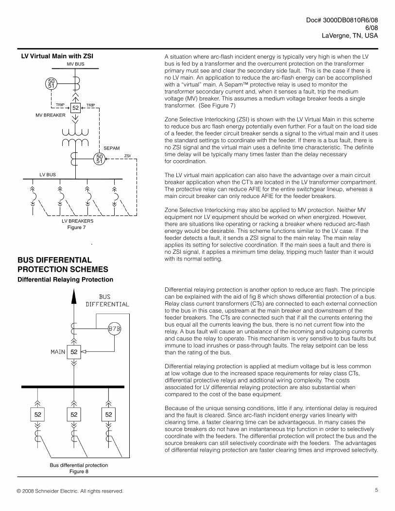
BUS DIFFERENTIAL PROTECTION SCHEMES
Differential relaying protection is another option to reduce arc flash. The principle can be explained with the aid of fig 8 which shows differential protection of a bus. Relay class current transformers (CTs) are connected to each external connection to the bus in this case, upstream at the main breaker and downstream of the feeder breakers. The CTs are connected such that if all the currents entering the bus equal all the currents leaving the bus, there is no net current flow into the relay. A bus fault will cause an unbalance of the incoming and outgoing currents and cause the relay to operate. This mechanism is very sensitive to bus faults but immune to load inrushes or pass-through faults. The relay setpoint can be less than the rating of the bus.
Differential relaying protection is applied at medium voltage but is less common at low voltage due to the increased space requirements for relay class CTs, differential protective relays and additional wiring complexity. The costs associated for LV differential relaying protection are also substantial when compared to the cost of the base equipment.
Because of the unique sensing conditions, little if any, intentional delay is required and the fault is cleared. Since arc-flash incident energy varies linearly with clearing time, a faster clearing time can be advantageous. In many cases the source breakers do not have an instantaneous trip function in order to selectively coordinate with the feeders. The differential protection will protect the bus and the source breakers can still selectively coordinate with the feeders. The advantages of differential relaying protection are faster clearing times and improved selectivity.
Differential Relaying Protection
Bus differential protectionFigure 8
LV Virtual Main with ZSI
52
A situation where arc-flash incident energy is typically very high is when the LV bus is fed by a transformer and the overcurrent protection on the transformer primary must see and clear the secondary side fault. This is the case if there is no LV main. An application to reduce the arc-flash energy can be accomplished with a “virtual” main. A Sepam™ protective relay is used to monitor the transformer secondary current and, when it senses a fault, trip the medium voltage (MV) breaker. This assumes a medium voltage breaker feeds a single transformer. (See Figure 7)
Zone Selective Interlocking (ZSI) is shown with the LV Virtual Main in this scheme to reduce bus arc flash energy potentially even further. For a fault on the load side of a feeder, the feeder circuit breaker sends a signal to the virtual main and it uses the standard settings to coordinate with the feeder. If there is a bus fault, there is no ZSI signal and the virtual main uses a definite time characteristic. The definite time delay will be typically many times faster than the delay necessary for coordination.
The LV virtual main application can also have the advantage over a main circuit breaker application when the CT’s are located in the LV transformer compartment. The protective relay can reduce AFIE for the entire switchgear lineup, whereas a main circuit breaker can only reduce AFIE for the feeder breakers.
Zone Selective Interlocking may also be applied to MV protection. Neither MV equipment nor LV equipment should be worked on when energized. However, there are situations like operating or racking a breaker where reduced arc-flash energy would be desirable. This scheme functions similar to the LV case. If the feeder detects a fault, it sends a ZSI signal to the main relay. The main relay applies its setting for selective coordination. If the main sees a fault and there is no ZSI signal, it applies a minimum time delay, tripping much faster than it would with its normal setting.
Figure 7

6 © 2008 Schneider Electric. All rights reserved.
Doc# 3000DB0810R6/08 06/08LaVergne, TN, USA
AFIE TEMPORARY REDUCTION METHODS
In response to the introduction of Square D® Masterpact circuit breakers with superior arc-flash protection characteristics, some manufacturers have begun to offer alternative schemes based on a temporary compromise of selective coordination during maintenance activities. Square D has developed a method to temporarily reduce the short time delay setting of the breaker by means of an Alternate Maintenance Setting (AMS) switch. This would presumably be for the period in which maintenance is being performed on energized equipment downstream from the main switchgear. A similar method is to reduce the instantaneous trip settings of the upstream breaker feeding this equipment during maintenance. Lowering the instantaneous pick-up setting is functionally equivalent to lowering the short time delay pick-up setting. A further variation for MV arc flash protection is a switchable arc flash setting for the MV protective relay. The relay provides protection and selectivity when the normal settings are active. When the settings are switched to the alternate mode, selectivity may be temporarily sacrificed to achieve reduced incident energy. Finally, some protective devices support an alternate set of trip settings, whereby the trip characteristic can be changed – if desired – to an alternate faster setting during periods of maintenance.
Functionally these options do no more than a maintenance person might do by manually adjusting a breaker’s trip setting(s). However, each offers some measure of convenience, especially if multiple set points are to be changed.
In order to quantify the AFIE reduction required to justify the expense of one of these schemes, an arc-flash study must first be performed. Values must be calculated for each of the possible scenarios to determine if any practical difference to maintenance procedures (such as PPE levels) is even possible. For example, if 5 different instantaneous pickup settings are possible, then the study must evaluate all 5 alternate scenarios. In the case of the alternate short time delay setting, only one additional case must be considered. In any case, the study must be completed prior to equipment selection. Of course, this is rarely possible; thus, there is a strong possibility that these options may be purchased and never used.
Regardless of which of these methods is employed, it must be understood by the end user that the potential benefits of reduced AFIE are obtained at a cost. These methods introduce new risks which must be evaluated, add a number of new technical, maintenance, and safety (added steps to LOTO procedures) issues which must be addressed.
Switchable Protective Device Settings
Ref. Voltage: 480Current in Amps x 1
Example System 2 One LineFigure 9
Ref. Voltage: 480Current in Amps x 1
s
UTILITY SOURCE
MV FUSE
TRANSFORMER
MAIN CB
CBF1
CABLE 1
CB FD1
DISTRIBUTION SWITCHBOARD
MAIN SWITCHGEAR
Normal Coordination Figure 10a
AMS Switch Enabled Figure 10b

7© 2008 Schneider Electric. All rights reserved.
Doc# 3000DB0810R6/08 6/08
LaVergne, TN, USA
RISKS WITH ALTERNATE TEMPORARY SCHEMES
Sacrificing selective coordination temporarily during maintenance may have its appeal, but like any complex problem, there are many factors to consider. First, the end user must understand the risks:
• Impact of lost selectivity. Protective devices are set in accordance with a study for a reason. Compromising selectivity – even temporarily – puts continuity of service at risk. A fault (not just an arc fault) that would have been harmlessly cleared as intended by the nearest upstream protective device now has the potential to interrupt service on a wider scale. This is ironic, since presumably the reason to work on the equipment while energized was to avoid downtime, even if exposing personnel to higher risk.
• Nuisance trips. You probably would not ask maintenance personnel to lower the instantaneous pickup setting of a LVPCB while under load, but that is exactly what one manufacturer’s maintenance switch does. Unless a study can reliably ensure that the alternate settings are above normal motor inrush currents, etc, there is a risk that the breaker will trip unnecessarily.
• New hazards. Even if selectivity can be sacrificed temporarily, the noise and vibration of an unnecessary LVPCB trip could startle workers near the affected switchgear and introduce a new hazard.
• Possibility that the wrong upstream breaker is switched. Unlike locking out an open breaker and testing to ensure that the downstream equipment is de-energized, there is no way to verify that the correct upstream breaker has been switched to its alternate settings. An additional burden is shifted to the maintenance procedures to somehow ensure that workers do not make a mistake.
• False sense of security. There is a risk that maintenance personnel will be lulled into a false sense of security in the belief that the slight reduction in AFIE levels makes energized equipment safe for work. While it may be possible to reduce the required level of PPE, the electrical hazard remains in effect.
In addition, the following maintenance and safety procedure issues must be addressed by the end user or his consultant:
• Multiple study results. A second SC/TCC/AF study must be performed to determine the appropriate alternate settings (if indeed it is possible at all). Since there is a possibility that no such alternate characteristics are desirable, this study must be done before the equipment purchase, in order to avoid the purchase of extraneous features.
• Clear warning signs. Appropriate warning signs should be provided to maintenance personnel to alert them that switching to alternate settings will override normal selective coordination and increase the possibility of nuisance trips.
• Increased reliance on procedures. Maintenance procedures must somehow ensure that personnel working on downstream equipment, while relying on a maintenance switch in upstream switchgear, are sure they have correctly switched the corresponding breaker. In addition, procedures must ensure that the breaker is returned to its normal settings at the conclusion of maintenance activities.
• Equipment planning. It may be desirable to locate the maintenance switch for the corresponding breaker nearer to the affected downstream equipment, in order to ensure that no error is made regarding the assumption of upstream protection.
• Labeling issues. Introducing a second set of arc-flash calculations introduces new questions about the appropriate labels to alert personnel of the arc flash hazard with the switch in the off or on position. Multiple labels with different AFIE levels may be confusing to maintenance personnel. Additional administrative controls may be required based on the owner’s safety practices.
MAINTENANCE AND SAFETY CONSIDERATIONS
A A A
BBB
C C
D D
A
B
Arc-Flash Labeling is more complicated when alternate schemes are used.
Figure 11

8 © 2008 Schneider Electric. All rights reserved.
Doc# 3000DB0810R6/08 06/08LaVergne, TN, USA
CONCLUSIONS A variety of techniques have been introduced to reduce arc-flash incident energy (AFIE) levels. However, selective coordination of overcurrent protective devices is equally important and often misunderstood. The best solution is to use equipment specifically designed for this purpose, which provide superior AFIE reduction without sacrificing selectivity.
At low voltage (600V and below) Square D® Masterpact® low-voltage power circuit breakers offer increased arc-flash protection thanks to faster clearing times, especially at higher current levels. In addition to superior arc-flash protection inherent in their design, Masterpact breakers can be configured in a variety of “Zone Selective Interlocking” (ZSI) schemes to further enhance protection with no impact on selectivity. At higher voltages, SepamTM overcurrent relays can also be applied in ZSI solutions.
There may be some cases in which these optimal solutions cannot be employed. In such cases, alternative schemes that temporarily sacrifice selectivity may be used, such as the Square D® AMS Switch. However, the risks and technical issues associated with these schemes should be evaluated and understood by the end user or consultant.
In all cases a SC/TCC/AF study must be performed in order to calculate AFIE levels and AF boundaries throughout the power system. Since the study results can be affected by changes in the utility system and changes within the facility, it is recommended that the study be validated each year, or any time significant changes occur. Square D Services can provide a service agreement to ensure continuing arc-flash hazard compliance throughout the life of your facility.
[1] NFPA 70E, 2004 Standard for Electrical Safety in the Workplace, Quincy, MA: NFPA. [2] NFPA 70, 2005 National Electrical Code (NEC), Quincy, MA: NFPA.[3] IEEE Standard 1584-2002, IEEE Guide for Performing Arc-flash Hazard Calculations, New York, NY: IEEE.[4] Brown, William A. and Ron Shapiro, “A Comparison of Arc-flash Incident Energy Reduction Techniques Using Low-Voltage Power Circuit Breakers,” IEEE, 2006.[5] Weigel, Joseph and Jonathan Clough, “Minimizing the Risk of Arc-flash Incidents,” Plant Engineering Magazine, September 2003. [6] “Arc-flash Protection with Masterpact NW and NT Circuit Breakers, Data Bulletin 0613DB0202R603, Schneider Electric, 2003.
REFERENCES
Schneider Electric - North American Operating Division 295 Tech Park DriveLaVergne, TN 37086Tel: 866-466-7627 Toll FreePowerLogic.com
Square D® PZ4 Switchgear and QED-6 Switchboards are designed, built and tested to comply with industry standards including ANSI and UL Standards (C37.20.1, IEEE Standard for Metal-Enclosed Low-Voltage Power Circuit Breaker Switchgear, UL 1558, C37.20.2, IEEE Standard for Metal-clad Switchgear, C37.20.3, IEEE Standard for Metal-Enclosed Interrupter Switchgear and UL 891-Dead Front Switchboards). These standards do not require equipment to be tested for internal arcing faults.
Even with today’s enhanced designs of switchgear and switchboards, the use of an AMS Type Switch on a main breaker does not provide the degree of AFIE reduction that may be assumed. There is no guarantee that the arcing fault on the main bus will not propagate ahead of the main breaker in which case, the reduction of AFIE would be dependent upon the upstream device’s characteristics.
EQUIPMENTCONSIDERATIONS
Square D, Masterpact, and Sepam are trademarks or registered trademarks of Schneider Electric and/or its affiliates in the United States and/or other countries.