Embed Size (px)
Citation preview
CAFCO® 300 ACSpray-Applied Fireproofing
Technical Data Sheet
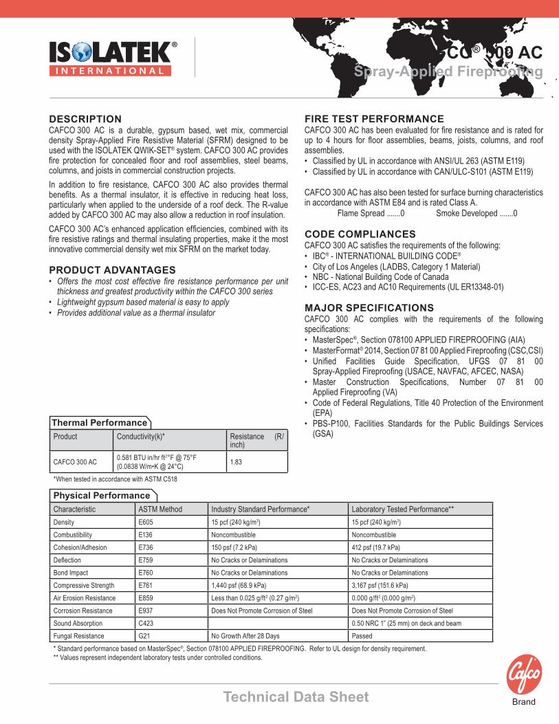
DESCRIPTION CAFCO 300 AC is a durable, gypsum based, wet mix, commercial density Spray-Applied Fire Resistive Material (SFRM) designed to be used with the ISOLATEK QWIK-SET® system. CAFCO 300 AC provides fire protection for concealed floor and roof assemblies, steel beams, columns, and joists in commercial construction projects.In addition to fire resistance, CAFCO 300 AC also provides thermal benefits. As a thermal insulator, it is effective in reducing heat loss, particularly when applied to the underside of a roof deck. The R-value added by CAFCO 300 AC may also allow a reduction in roof insulation.CAFCO 300 AC’s enhanced application efficiencies, combined with its fire resistive ratings and thermal insulating properties, make it the most innovative commercial density wet mix SFRM on the market today.
PRODUCT ADVANTAGES• Offers the most cost effective fire resistance performance per unit
thickness and greatest productivity within the CAFCO 300 series• Lightweight gypsum based material is easy to apply• Provides additional value as a thermal insulator
Characteristic ASTM Method Industry Standard Performance* Laboratory Tested Performance**Density E605 15 pcf (240 kg/m3) 15 pcf (240 kg/m3)Combustibility E136 Noncombustible NoncombustibleCohesion/Adhesion E736 150 psf (7.2 kPa) 412 psf (19.7 kPa)Deflection E759 No Cracks or Delaminations No Cracks or DelaminationsBond Impact E760 No Cracks or Delaminations No Cracks or DelaminationsCompressive Strength E761 1,440 psf (68.9 kPa) 3,167 psf (151.6 kPa)Air Erosion Resistance E859 Less than 0.025 g/ft2 (0.27 g/m2) 0.000 g/ft2 (0.000 g/m2)Corrosion Resistance E937 Does Not Promote Corrosion of Steel Does Not Promote Corrosion of Steel Sound Absorption C423 0.50 NRC 1” (25 mm) on deck and beam Fungal Resistance G21 No Growth After 28 Days Passed * Standard performance based on MasterSpec®, Section 078100 APPLIED FIREPROOFING. Refer to UL design for density requirement. ** Values represent independent laboratory tests under controlled conditions.
FIRE TEST PERFORMANCECAFCO 300 AC has been evaluated for fire resistance and is rated for up to 4 hours for floor assemblies, beams, joists, columns, and roof assemblies.• Classified by UL in accordance with ANSI/UL 263 (ASTM E119)• Classified by UL in accordance with CAN/ULC-S101 (ASTM E119)
CAFCO 300 AC has also been tested for surface burning characteristics in accordance with ASTM E84 and is rated Class A. Flame Spread .......0 Smoke Developed .......0
CODE COMPLIANCESCAFCO 300 AC satisfies the requirements of the following: • IBC® - INTERNATIONAL BUILDING CODE® • City of Los Angeles (LADBS, Category 1 Material)• NBC - National Building Code of Canada • ICC-ES, AC23 and AC10 Requirements (UL ER13348-01)
MAJOR SPECIFICATIONSCAFCO 300 AC complies with the requirements of the following specifications:• MasterSpec®, Section 078100 APPLIED FIREPROOFING (AIA)• MasterFormat® 2014, Section 07 81 00 Applied Fireproofing (CSC,CSI)• Unified Facilities Guide Specification, UFGS 07 81 00
Spray-Applied Fireproofing (USACE, NAVFAC, AFCEC, NASA)• Master Construction Specifications, Number 07 81 00
Applied Fireproofing (VA)• Code of Federal Regulations, Title 40 Protection of the Environment
(EPA)• PBS-P100, Facilities Standards for the Public Buildings Services
(GSA)
Physical Performance
Product Conductivity(k)* Resistance (R/inch)
CAFCO 300 AC 0.581 BTU in/hr ft2°F @ 75°F(0.0838 W/m•K @ 24°C) 1.83
*When tested in accordance with ASTM C518
Thermal Performance
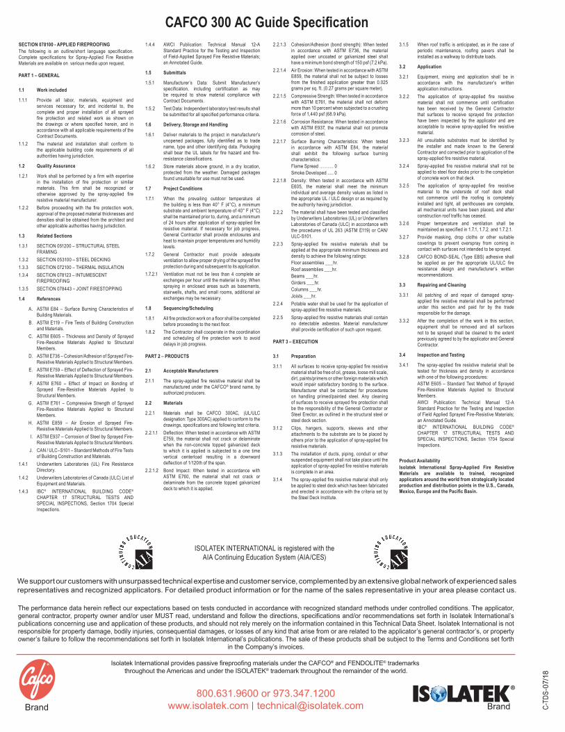
CAFCO 300 AC Guide SpecificationSECTION 078100 - APPLIED FIREPROOFING The following is an outline/short language specification. Complete specifications for Spray-Applied Fire Resistive Materials are available on various media upon request.
PART 1 – GENERAL
1.1 Work included
1.1.1 Provide all labor, materials, equipment and services necessary for, and incidental to, the complete and proper installation of all sprayed fire protection and related work as shown on the drawings or where specified herein, and in accordance with all applicable requirements of the Contract Documents.
1.1.2 The material and installation shall conform to the applicable building code requirements of all authorities having jurisdiction.
1.2 Quality Assurance
1.2.1 Work shall be performed by a firm with expertise in the installation of fire protection or similar materials. This firm shall be recognized or otherwise approved by the spray-applied fire resistive material manufacturer.
1.2.2 Before proceeding with the fire protection work, approval of the proposed material thicknesses and densities shall be obtained from the architect and other applicable authorities having jurisdiction.
1.3 Related Sections
1.3.1 SECTION 051200 – STRUCTURAL STEEL FRAMING
1.3.2 SECTION 053100 – STEEL DECKING1.3.3 SECTION 072100 – THERMAL INSULATION1.3.4 SECTION 078123 – INTUMESCENT
FIREPROOFING1.3.5 SECTION 078443 – JOINT FIRESTOPPING
1.4 References
A. ASTM E84 – Surface Burning Characteristics of Building Materials.
B. ASTM E119 – Fire Tests of Building Construction and Materials.
C. ASTM E605 – Thickness and Density of Sprayed Fire-Resistive Materials Applied to Structural Members.
D. ASTM E736 – Cohesion/Adhesion of Sprayed Fire-Resistive Materials Applied to Structural Members.
E. ASTM E759 – Effect of Deflection of Sprayed Fire-Resistive Materials Applied to Structural Members.
F. ASTM E760 – Effect of Impact on Bonding of Sprayed Fire-Resistive Materials Applied to Structural Members.
G. ASTM E761 – Compressive Strength of Sprayed Fire-Resistive Materials Applied to Structural Members.
H. ASTM E859 – Air Erosion of Sprayed Fire-Resistive Materials Applied to Structural Members.
I. ASTM E937 – Corrosion of Steel by Sprayed Fire-Resistive Materials Applied to Structural Members.
J. CAN / ULC–S101 – Standard Methods of Fire Tests of Building Construction and Materials.
1.4.1 Underwriters Laboratories (UL) Fire Resistance Directory.
1.4.2 Underwriters Laboratories of Canada (ULC) List of Equipment and Materials.
1.4.3 IBC® INTERNATIONAL BUILDING CODE® CHAPTER 17 STRUCTURAL TESTS AND SPECIAL INSPECTIONS, Section 1704 Special Inspections.
1.4.4 AWCI Publication: Technical Manual 12-A Standard Practice for the Testing and Inspection of Field-Applied Sprayed Fire Resistive Materials; an Annotated Guide.
1.5 Submittals
1.5.1 Manufacturer’s Data: Submit Manufacturer’s specification, including certification as may be required to show material compliance with Contract Documents.
1.5.2 Test Data: Independent laboratory test results shall be submitted for all specified performance criteria.
1.6 Delivery, Storage and Handling
1.6.1 Deliver materials to the project in manufacturer’s unopened packages, fully identified as to trade name, type and other identifying data. Packaging shall bear the UL labels for fire hazard and fire-resistance classifications.
1.6.2 Store materials above ground, in a dry location, protected from the weather. Damaged packages found unsuitable for use must not be used.
1.7 Project Conditions
1.7.1 When the prevailing outdoor temperature at the building is less than 40° F (4°C), a minimum substrate and ambient temperature of 40° F (4°C) shall be maintained prior to, during, and a minimum of 24 hours after application of spray-applied fire resistive material. If necessary for job progress, General Contractor shall provide enclosures and heat to maintain proper temperatures and humidity levels.
1.7.2 General Contractor must provide adequate ventilation to allow proper drying of the sprayed fire protection during and subsequent to its application.
1.7.2.1 Ventilation must not be less than 4 complete air exchanges per hour until the material is dry. When spraying in enclosed areas such as basements, stairwells, shafts, and small rooms, additional air exchanges may be necessary.
1.8 Sequencing/Scheduling
1.8.1 All fire protection work on a floor shall be completed before proceeding to the next floor.
1.8.2 The Contractor shall cooperate in the coordination and scheduling of fire protection work to avoid delays in job progress.
PART 2 – PRODUCTS
2.1 Acceptable Manufacturers
2.1.1 The spray-applied fire resistive material shall be manufactured under the CAFCO® brand name, by authorized producers.
2.2 Materials
2.2.1 Materials shall be CAFCO 300AC, (UL/ULC designation: Type 300AC) applied to conform to the drawings, specifications and following test criteria.
2.2.1.1 Deflection: When tested in accordance with ASTM E759, the material shall not crack or delaminate when the non-concrete topped galvanized deck to which it is applied is subjected to a one time vertical centerload resulting in a downward deflection of 1/120th of the span.
2.2.1.2 Bond Impact: When tested in accordance with ASTM E760, the material shall not crack or delaminate from the concrete topped galvanized deck to which it is applied.
2.2.1.3 Cohesion/Adhesion (bond strength): When tested in accordance with ASTM E736, the material applied over uncoated or galvanized steel shall have a minimum bond strength of 150 psf (7.2 kPa).
2.2.1.4 Air Erosion: When tested in accordance with ASTM E859, the material shall not be subject to losses from the finished application greater than 0.025 grams per sq. ft. (0.27 grams per square meter).
2.2.1.5 Compressive Strength: When tested in accordance with ASTM E761, the material shall not deform more than 10 percent when subjected to a crushing force of 1,440 psf (68.9 kPa).
2.2.1.6 Corrosion Resistance: When tested in accordance with ASTM E937, the material shall not promote corrosion of steel.
2.2.1.7 Surface Burning Characteristics: When tested in accordance with ASTM E84, the material shall exhibit the following surface burning characteristics: Flame Spread ............ 0 Smoke Developed ..... 0
2.2.1.8 Density: When tested in accordance with ASTM E605, the material shall meet the minimum individual and average density values as listed in the appropriate UL / ULC design or as required by the authority having jurisdiction.
2.2.2 The material shall have been tested and classified by Underwriters Laboratories (UL) or Underwriters Laboratories of Canada (ULC) in accordance with the procedures of UL 263 (ASTM E119) or CAN/ULC-S101.
2.2.3 Spray-applied fire resistive materials shall be applied at the appropriate minimum thickness and density to achieve the following ratings: Floor assemblies ___hr. Roof assemblies ___hr. Beams ___hr. Girders ___hr. Columns ___hr.Joists ___hr.
2.2.4 Potable water shall be used for the application of spray-applied fire resistive materials.
2.2.5 Spray-applied fire resistive materials shall contain no detectable asbestos. Material manufacturer shall provide certification of such upon request.
PART 3 – EXECUTION
3.1 Preparation
3.1.1 All surfaces to receive spray-applied fire resistive material shall be free of oil, grease, loose mill scale, dirt, paints/primers or other foreign materials which would impair satisfactory bonding to the surface. Manufacturer shall be contacted for procedures on handling primed/painted steel. Any cleaning of surfaces to receive sprayed fire protection shall be the responsibility of the General Contractor or Steel Erector, as outlined in the structural steel or steel deck section.
3.1.2 Clips, hangers, supports, sleeves and other attachments to the substrate are to be placed by others prior to the application of spray-applied fire resistive materials.
3.1.3 The installation of ducts, piping, conduit or other suspended equipment shall not take place until the application of spray-applied fire resistive materials is complete in an area.
3.1.4 The spray-applied fire resistive material shall only be applied to steel deck which has been fabricated and erected in accordance with the criteria set by the Steel Deck Institute.
3.1.5 When roof traffic is anticipated, as in the case of periodic maintenance, roofing pavers shall be installed as a walkway to distribute loads.
3.2 Application
3.2.1 Equipment, mixing and application shall be in accordance with the manufacturer’s written application instructions.
3.2.2 The application of spray-applied fire resistive material shall not commence until certification has been received by the General Contractor that surfaces to receive sprayed fire protection have been inspected by the applicator and are acceptable to receive spray-applied fire resistive material.
3.2.3 All unsuitable substrates must be identified by the installer and made known to the General Contractor and corrected prior to application of the spray-applied fire resistive material.
3.2.4 Spray-applied fire resistive material shall not be applied to steel floor decks prior to the completion of concrete work on that deck.
3.2.5 The application of spray-applied fire resistive material to the underside of roof deck shall not commence until the roofing is completely installed and tight, all penthouses are complete, all mechanical units have been placed, and after construction roof traffic has ceased.
3.2.6 Proper temperature and ventilation shall be maintained as specified in 1.7.1, 1.7.2. and 1.7.2.1.
3.2.7 Provide masking, drop cloths or other suitable coverings to prevent overspray from coming in contact with surfaces not intended to be sprayed.
3.2.8 CAFCO BOND-SEAL (Type EBS) adhesive shall be applied as per the appropriate UL/ULC fire resistance design and manufacturer’s written recommendations.
3.3 Repairing and Cleaning
3.3.1 All patching of and repair of damaged spray-applied fire resistive material shall be performed under this section and paid for by the trade responsible for the damage.
3.3.2 After the completion of the work in this section, equipment shall be removed and all surfaces not to be sprayed shall be cleaned to the extent previously agreed to by the applicator and General Contractor.
3.4 Inspection and Testing
3.4.1 The spray-applied fire resistive material shall be tested for thickness and density in accordance with one of the following procedures: ASTM E605 – Standard Test Method of Sprayed Fire-Resistive Materials Applied to Structural Members. AWCI Publication: Technical Manual 12-A Standard Practice for the Testing and Inspection of Field Applied Sprayed Fire-Resistive Materials; an Annotated Guide. IBC® INTERNATIONAL BUILDING CODE® CHAPTER 17 STRUCTURAL TESTS AND SPECIAL INSPECTIONS, Section 1704 Special Inspections.
Product AvailabilityIsolatek International Spray-Applied Fire Resistive Materials are available to trained, recognized applicators around the world from strategically located production and distribution points in the U.S., Canada, Mexico, Europe and the Pacific Basin.
C-TD
S-07
/18
ISOLATEK INTERNATIONAL is registered with theAIA Continuing Education System (AIA/CES)
We support our customers with unsurpassed technical expertise and customer service, complemented by an extensive global network of experienced sales representatives and recognized applicators. For detailed product information or for the name of the sales representative in your area please contact us.
The performance data herein reflect our expectations based on tests conducted in accordance with recognized standard methods under controlled conditions. The applicator, general contractor, property owner and/or user MUST read, understand and follow the directions, specifications and/or recommendations set forth in Isolatek International’s publications concerning use and application of these products, and should not rely merely on the information contained in this Technical Data Sheet. Isolatek International is not responsible for property damage, bodily injuries, consequential damages, or losses of any kind that arise from or are related to the applicator’s general contractor’s, or property owner’s failure to follow the recommendations set forth in Isolatek International’s publications. The sale of these products shall be subject to the Terms and Conditions set forth
in the Company’s invoices.
Isolatek International provides passive fireproofing materials under the CAFCO® and FENDOLITE® trademarks throughout the Americas and under the ISOLATEK® trademark throughout the remainder of the world.
1 of 2
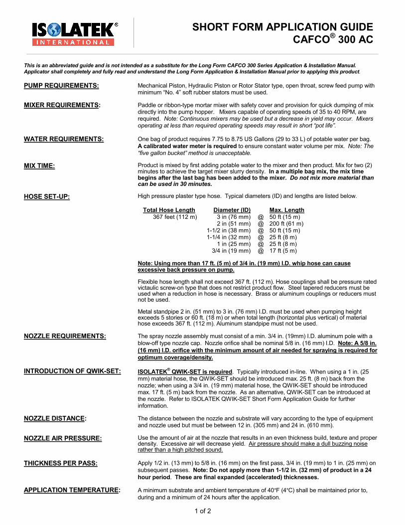
This is an abbreviated guide and is not intended as a substitute for the Long Form CAFCO 300 Series Application & Installation Manual. Applicator shall completely and fully read and understand the Long Form Application & Installation Manual prior to applying this product. PUMP REQUIREMENTS: Mechanical Piston, Hydraulic Piston or Rotor Stator type, open throat, screw feed pump with minimum “No. 4” soft rubber stators must be used. MIXER REQUIREMENTS: Paddle or ribbon-type mortar mixer with safety cover and provision for quick dumping of mix directly into the pump hopper. Mixers capable of operating speeds of 35 to 40 RPM, are required. Note: Continuous mixers may be used but a decrease in yield may occur. Mixers
operating at less than required operating speeds may result in short “pot life”. WATER REQUIREMENTS: One bag of product requires 7.75 to 8.75 US Gallons (29 to 33 L) of potable water per bag. A calibrated water meter is required to ensure constant water volume per mix. Note: The “five gallon bucket” method is unacceptable. MIX TIME: Product is mixed by first adding potable water to the mixer and then product. Mix for two (2) minutes to achieve the target mixer slurry density. In a multiple bag mix, the mix time begins after the last bag has been added to the mixer. Do not mix more material than can be used in 30 minutes. HOSE SET-UP: High pressure plaster type hose. Typical diameters (ID) and lengths are listed below.
Total Hose Length
Diameter (ID)
Max. Length
367 feet (112 m) 3 in (76 mm) @ 50 ft (15 m) 2 in (51 mm) @ 200 ft (61 m) 1-1/2 in (38 mm) @ 50 ft (15 m) 1-1/4 in (32 mm) @ 25 ft (8 m) 1 in (25 mm) @ 25 ft (8 m) 3/4 in (19 mm) @ 17 ft (5 m)
Note: Using more than 17 ft. (5 m) of 3/4 in. (19 mm) I.D. whip hose can cause excessive back pressure on pump. Flexible hose length shall not exceed 367 ft. (112 m). Hose couplings shall be pressure rated victaulic screw-on type that does not restrict product flow. Steel tapered reducers must be used when a reduction in hose is necessary. Brass or aluminum couplings or reducers must not be used. Metal standpipe 2 in. (51 mm) to 3 in. (76 mm) I.D. must be used when pumping height exceeds 5 stories or 60 ft. (18 m) or when total length (horizontal plus vertical) of material hose exceeds 367 ft. (112 m). Aluminum standpipe must not be used. NOZZLE REQUIREMENTS: INTRODUCTION OF QWIK-SET:
The spray nozzle assembly must consist of a min. 3/4 in. (19mm) I.D. aluminum pole with a blow-off type nozzle cap. Nozzle orifice shall be nominal 5/8 in. (16 mm) I.D. Note: A 5/8 in. (16 mm) I.D. orifice with the minimum amount of air needed for spraying is required for optimum coverage/density. ISOLATEK® QWIK-SET is required. Typically introduced in-line. When using a 1 in. (25 mm) material hose, the QWIK-SET should be introduced max. 25 ft. (8 m) back from the nozzle; when using a 3/4 in. (19 mm) material hose, the QWIK-SET should be introduced max. 17 ft. (5 m) back from the nozzle. As an alternative, QWIK-SET can be introduced at the nozzle. Refer to ISOLATEK QWIK-SET Short Form Application Guide for further information. NOZZLE DISTANCE: The distance between the nozzle and substrate will vary according to the type of equipment and nozzle used but must be between 12 in. (305 mm) and 24 in. (610 mm). NOZZLE AIR PRESSURE: Use the amount of air at the nozzle that results in an even thickness build, texture and proper density. Excessive air will decrease yield. Air pressure should make a dull buzzing noise rather than a high pitched sound. THICKNESS PER PASS: Apply 1/2 in. (13 mm) to 5/8 in. (16 mm) on the first pass, 3/4 in. (19 mm) to 1 in. (25 mm) on subsequent passes. Note: Do not apply more than 1-1/2 in. (32 mm) of product in a 24 hour period. These are final expanded (accelerated) thicknesses. APPLICATION TEMPERATURE: A minimum substrate and ambient temperature of 40°F (4°C) shall be maintained prior to, during and a minimum of 24 hours after the application.
SHORT FORM APPLICATION GUIDE CAFCO® 300 AC

2 of 2
9/16
SURFACE PREPARATION: Ensure surfaces are clean and free of dirt, oil, grease, loose mill scale, paints/primers (other than those approved by Isolatek) and any other materials that may impair adhesion. For applications to primed steel, contact Isolatek Technical Services Department. Note: Some substrates require the use of CAFCO® BOND-SEAL (adhesive), CAFCO® PRE-COAT, or metal lath. Refer to the CAFCO 300 Series Application & Installation Manual for specific requirements. SET-TIME: CAFCO 300 AC will set in approximately 10 - 20 minutes depending on temperature and humidity conditions. Do not re-temper the product after it sets. See ISOLATEK QWIK-SET Short Form Application Guide for further information. VENTILATION: Provide a minimum of 4 complete air exchanges per hour until the material is dry. SAFETY PRECAUTIONS: CAFCO 300 AC is slippery when mixed with water. Do not allow wet material to remain on scaffolds, ladder rungs or floors. Walking on wet material may result in slips or falls. Signage must be posted in areas where the spray application of CAFCO 300 AC is ongoing to warn other trades of slip hazards. CALCULATING MIXER DENSITIES:
1. Weigh an empty 1036cc CAFCO cup and tare the scale to account for the cup weight. 2. Fill the cup with material from the pump hopper. Then gently tap the cup on a hard surface to eliminate all air pockets. 3. Level the material with top of cup. 4. Weigh the filled cup in grams. 5. Compare weight in grams to the mixer density in chart below. ESTIMATING CAFCO 300 AC MIXER DENSITY FROM WET CUP WEIGHTS MIXER DENSITY Using 8.5 US Gals (32 L) Water WET CUP WEIGHT (Grams) PCF (kg/m3) 748 45 (721) 781 47 (753) 815 OPTIMUM 49 (785) 846 RANGE 51 (817) 880 53 (849) 914 55 (881)
Cup Size = 1036cc CALCULATING NOZZLE DENSITIES: (Estimating Yield/Bag from Nozzle Wet Cup Weights)
1. Weigh an empty 1036cc CAFCO cup and tare the scale to account for the cup weight.
2. While the pump and atomizing air are running, place the nozzle inside cup and slowly pull back as the cup fills.
3. Level CAFCO 300 AC with the top of cup, being careful not to compress the CAFCO 300 AC. Leveling should be repeated until the material stops swelling in cup. When leveling the CAFCO 300 AC, angle the spatula so that it is cutting the excess material as opposed to troweling/compressing it.
4. Weigh the filled cup in grams. 5. Using the chart below, determine the corresponding density and yield based
on the water usage rate and the weight of the cup. 6. Adjust the QWIK-SET flow rate and repeat the steps above until the desired density and yield are achieved.
7.75 gal (29 L)/bag
Nozzle Cup Weight in grams
(Net mat'l wt)
8.0 gal (30 L)/bag
Nozzle Cup Weight in grams
(Net mat'l wt)
8.25 gal (31 L)/bag Nozzle Cup
Weight in grams (Net mat'l wt)
8.5 gal (32 L)/bag Nozzle Cup
weight in grams (Net mat'l wt)
8.75 gal (33 L)/bag Nozzle Cup
weight in grams (Net mat'l wt)
DRY DENSITY (Estimated)
PCF (kg/m3)
YIELD Est. Gross Yield/Bag
Bd. ft. (m2@1 mm)
590 601 611 622 633 17.5 (280) 40 (94) 573 584 594 604 615 17 (272) 41 (97) 540 549 559 569 578 16 (256) 43 (101) 506 515 524 533 547 15 (240) 46 (109)
Note: If you are having difficulty achieving these nozzle cup weights, please contact the Isolatek International Technical Service Department for assistance. * Nozzle weights are based on a cup with a volume of 1036cc.
NOTE: Only the listed equipment, nozzles and procedures are approved for applying CAFCO 300 AC. Deviations from these requirements will result in product not meeting claims as published in the literature. For additional information, please contact the Technical Service Department.
Note: UL minimum average density for CAFCO 300 AC is 15 pcf (240 kg/m3) and the minimum individual density is 14 pcf (224 kg/m3). When applying CAFCO 300 AC to cellular deck a minimum average density of 17.5 pcf (280 kg/m3) and a minimum individual density of 16.0 pcf (256 kg/m3) must be maintained. Warning: Exceeding 46 bd.ft./bag (109 m2@1mm) will result in densities below 15 pcf (240 kg/m3)