Embed Size (px)
Citation preview

PERIMETER FIRE BARRIER SYSTEM GUIDELIFE SAFETY | CODES AND COMPLIANCE | COMPONENTS AND SYSTEMS

2
Cover:ONE WORLD TRADE CENTER
New York, NY
Introduction ...................................................................................................................................... 3
A Brief History of Perimeter Fire Containment .......................................................................... 4
Life Safety ........................................................................................................................................ 6
Fire Testing Standards ................................................................................................................... 7ASTM E119 ....................................................................................................................................................7ASTM E2307 .................................................................................................................................................8
International Building Codes and Compliance .......................................................................... 9
Six Critical Components of a Listed Perimeter Fire Barrier Assembly ............................... 12Aluminum-framed Curtain Wall System ........................................................................12Steel-framed Curtain Wall System ..............................................................................14
Most Common Perimeter Fire Barrier Systems (Top 5) ......................................................... 16
Smoke Sealants ............................................................................................................................. 18
Spandrel Requirements ............................................................................................................... 19
Special Conditions ........................................................................................................................20Short spandrel heights ............................................................................................20Wide spandrel conditions .........................................................................................20Steel back pans .....................................................................................................21Curved spandrel walls .............................................................................................23Angled spandrel walls .............................................................................................24Exposed curtain wall anchors at the floor line ................................................................25
Combustible Building Materials Used in Perimeter Fire Barrier Systems .........................25
Engineering Judgments ...............................................................................................................26
Project Spotlight ...........................................................................................................................28

3
Each year in the U.S., fire is responsible for about 3,000 deaths and nearly $12 billion in property loss.1 In non-residential buildings alone, losses in 2014 were nearly $3 billion.2
While these statistics are sobering, fire losses—both in life and property—have been decreasing over the past decade,3 thanks in part to better fire barrier strategies.
Even when lives are spared, fire losses can be devastating. A proper fire barrier system helps save buildings, intellectual property and business capital, along with the people inside a structure.
Thermafiber Insolutions® provide perimeter fire barrier solutions to fit the unique design needs of today’s innovative commercial buildings. This five-step approach saves time and budget on projects, while delivering superior performance that meets demanding building standards.
Perimeter Fire Barrier Systems:Life Safety and property protection through innovation and science
Thermafiber, Inc. is a pioneer of today’s perimeter fire barrier systems using mineral wool insulation.* Today, Thermafiber is committed to helping architects and builders improve the safety of their structures. We’ve prepared this guide to fire barrier standards and installation, for easy-to-reference information to help maximize the fire safety of your next project.
1 2 3 4 5
All-phase consultation
Engineering judgments, accurate CAD drawings and a knowledge base of building codes and insulation application techniques
High-performance products
Insulation that has been extensively evaluated to resist fire at temperatures above 2,000° F (1,093° C).
Cost-saving insulation hanger systems
Methods that lock fire barriers into place for faster, more accurate and safer insulation positioning
Labor-saving customization and packaging
Systems to help ensure the right sizes, shapes and pieces to get to the right places on your project
Contributes to green building guides
Insulation that helps earn your building LEED credits with a minimum of 70% recycled content, and up to 75% recycled content available as recommended by the EPA.
Thermafiber Insolutions®
*Thermafiber, Inc. was a division of United States Gypsum Company (USG) from 1959-1996.

4
A Brief History of Perimeter Fire ContainmentArchitects and curtain wall designers have long recognized that the void created between the floor slab and exterior wall, if left unprotected, would allow fire and smoke to propagate to the floor above. The logical fix seemed to be to fill the void with fire resistant material. However, if the void is simply filled with mineral wool and a portion of the spandrel area is left unprotected, the curtain wall will fail, causing the mineral wool to fall out of the void. Once the mineral wool at the joint is lost, fire will propagate through the opening, allowing fire to engage combustibles in the floor above. This effect was demonstrated in a 1999 study by the Loss Prevention Council in the UK.
While the UK was drawing its conclusions, Thermafiber, Inc. was also conducting fire testing. In fact, Thermafiber pioneered the perimeter fire containment system and helped UL develop a test standard so that these systems could be evaluated by their lab and listed in their fire resistance directory. The first UL-tested and listed assembly was conducted in 1997.
As the cross-section drawing illustrates, a test in 1999 by the Loss Prevention Council in the United Kingdom installed mineral wool between the glass and face of the floor slab (Fig. 1).
Within the first 10 minutes of the fire, the glass broke out and the Safing fell out of the void allowing fire to propagate to the next floor. In depth testing conducted in collaboration between Thermafiber and Underwriters Laboratories (UL) lead to the development of a test standard that ultimately became ASTM E2307, the test standard for evaluating perimeter fire containment (Fig. 2).
Following more than 20 years of various code requirements for the floor-to-floor fire containment in the curtain wall condition, ASTM E-2307 was published as the definitive test method for evaluating the performance of perimeter fire containment assemblies and quickly adopted in the 2006 edition of the International Building Code (IBC).
Fig.1 - Typical curtain wall system panel
Fig. 2 UL's First Published Curtain Wall Assembly: CW-S-2001 Issued: 4/14/97

5
Paths of Fire Propagation
This illustration shows how when a curtain wall is left unprotected, fire can spread vertically.
Here, both the curtain wall spandrel and interior joint are protected by mineral wool, preventing the spread of fire.
This photo shows the results of “leap frog” fire propagation. Note how the fire has spread vertically along the outside of the high rise.
There are two paths of fire propagation:
1. Fire can spread through the interior joint between the rated floor assembly and unrated curtain wall.
2. Fire can also propagate via the exterior of the building, an effect known as “leap frog,” in conditions where there is zero, or very short, spandrel protection. Leap frog fire spread occurs when the fire breaks out the vision glass on the floor where the fire originated, allowing flame and hot gases to escape to the outside of the building. The fire then breaks out the vision glass on the floor above, and enters into the interior space, engaging combustibles and continuing to cause fire spread vertically, via the exterior of the building. Fire can also spread via the interior cavity of an unprotected or improperly protected spandrel area.
Vertical fire spread in an unprotected curtain wall Vertical fire spread when curtain wall is protected by mineral wool

6
Life SafetyThe Balanced Approach to Life Safety
There are three elements to address life safety that are used by the building community and required by code:
1. Fire containment utilizing fire-rated construction to minimize occupant exposure to fire and smoke
2. Ability to suppress and limit fire spread
3. Helping to maintain structural integrity of the building during a fire
Compartmentation(passive systems)
Detection Suppression(active systems)
• Installation of sprinkler systems is the most common method of suppression.
• A system is considered “active” if it requires some form of activation to switch the system to the “on” position.
• The system must turn on in order for it to work.
• Detection includes alarm systems, such as smoke and heat detectors, that notify the occupants that there is a safety hazard.
• Once installed, passive systems do not require activation for operation.
• If properly installed, passive systems are guaranteed to work.
• Passive systems contain the fire to the room of origin, allowing occupants to safely evacuate the building and allowing fire personnel to safely enter the building to extinguish the fire.
Elements That Contribute to Life Safety in High-rise Construction:
Balancing the Three Elements of Life Safety
1 2 3
We’ve learned from history not to rely solely on any one of these elements in our buildings, but to include all three. This is known as the balanced approach to life safety. These three elements are required to increase the probability of successfully maximizing life safety in high-rise buildings. Life safety can be defined as the preservation of human life in the event of a catastrophic event such as a fire.
Detection Suppression (active systems) Compartmentation (passive systems)1 2 3

7
2400°F1316°C
2080°F
Thermafiber® Time Temp Curve
1980°F
1510°F
1220°F
1050°F
790°F
450°F
392°F
300°F
Hours
(1)
Tem
pera
ture
At 5 hr. ThermafiberInsulation (1) is still intact.Test terminated withoutfailure
Copper melts
Plate glass melts
Aluminum melts
Glass-fiberinsulation melts
Zinc melts
Cellulose pyrolyzes
Not for service operation at this temperature. Refer to the appropriate Thermafiber Insulation literaturewhich states recommended maximum service temperature limits of individual products.Time-temperature curve from “Standard of Methods of Fire Tests of Building Constructions and Materials.”(ASTM E119-81)
Spray foam flash point
Rigid foam melts
2200°F1204°C
2000°F1093°C
1800°F982°C
1600°F871°C
1400°F760°C
1200°F649°C
1000°F538°C
800°F427°C
600°F316°C
400°F204°C
200°F93°C
-18°F
0 1 2 3 4 5 6 7 8
Fire Testing Standards for Evaluating Performance of Common Building Materials When Exposed to a Commercial Fire ASTM E119⁴
In this test method, various types of building elements are exposed to fire for a predetermined time to measure which materials contain a fire and/or retain their structural integrity. The test exposes a material to a standard controlled fire to achieve specified temperatures throughout a specified time period. This follows a path known as the ASTM E119 Time-Temperature Curve, seen below.
ASTM E119 is an important test for evaluating building elements. However, ASTM E119 only tests fire exposure on one side of the assembly. For perimeter fire barrier systems, the correct ASTM standard to reference is ASTM E2307.
This illustrates why mineral wool is utilized in perimeter fire barrier systems as it is the only material tested and proven to perform at temperatures above 2,000° F (1,093° C) after five hours of fire exposure.
After five hours, the test was terminated, with mineral wool insulation still fully intact. No other building element outlasts mineral wool insulation in these simulated fire conditions, making it the ideal choice for fire barrier assemblies.
Exposure at the beginning of the test takes place quickly, with temperatures growing very rapidly, as the red line shows. This quick temperature rise is typical of a real fire condition.
6 minutes into the test, temperatures reach 1050°F, melting any type of spray foam, zinc and glass fiber insulation.
Temperatures reach 1220°F at 9 minutes. Aluminum framing and curtain wall anchors begin to melt.
After 25 minutes, test temperatures reach 1510°F, melting plate glass.
At 5 hours and temperatures of 2080°F, mineral wool insulation remains fully intact.
!

8
Fire Testing Standards for Evaluating Fire Performance of Perimeter Fire Barrier Systems ASTM E2307⁵
ASTM E2307 measures the ability of perimeter fire barrier systems to maintain a seal and prevent interior fire spread as the exterior wall assembly deflects/deforms during fire exposure. ASTM E2307 determines the period of time that the perimeter fire barrier system will limit flame penetration through the opening between the exterior wall assembly and the floor assembly.
The ASTM E2307 test exposes the joint to fire from the room of fire origin. The exterior wall is also exposed to fire from both the interior and exterior, as the fire plume exits the room of origin through a window opening. After the first 30 minutes of the test, the ASTM E2307 test essentially parallels the ASTM E119 time-temperature in the test room for the remainder of the test.
View of the assembly as the fire begins with ignition of the room burner.
Approximately five minutes into the fire, to simulate vision glass breakage, and the window burner is ignited.
These are photos of an actual test per ASTM E2307.:
The aftermath of the fire shows the destruction caused by the flame and hot gases. Note the loss of the transom and mullions.
Thermafiber® Perimeter Fire Barrier Systems components and Thermafiber® Insolutions® Design and Installation Services have been awarded SAFETY Act Designation by the U.S. Department of Homeland Security (DHS). Under the SAFETY Act, commercial building professionals - including architects, engineers, contractors (both general and firestopping), smoke sealant manufacturers, curtain wall OEMs, as well as building owners - who use the the Thermafiber® SAFETY Act Desginated® solutions in their structures will receive powerful liability protection in the event of a foreign or domestic terrorist attack on that building. Visit SafetyAct.gov for more info.
9
International Building Codes and Compliance There are several sections of the code that relate to the protection of the exterior curtain wall condition. It is easy to misunderstand which code section to follow as it pertains to code-compliant perimeter fire barrier systems.
Section 705.8.5 Vertical Separation of Openings
Openings in exterior walls in adjacent stories shall be separated vertically to protect against fire spread on the exterior of the buildings where the openings are within 5 feet (1524 mm) of each other horizontally and the opening in the lower story is not a protected opening with a fire protection rating of not less than ¾ hour. Such openings shall be separated vertically at least 3 feet (914 mm) by spandrel girders, exterior walls or other similar assemblies that have a fire-resistance rating of at least 1 hour or by flame barriers that extend horizontally at least 30 inches (762 mm) beyond the exterior wall. Flame barriers shall have a fire-resistance rating of not less than 1 hour.
Exceptions:
1. This section shall not apply to buildings that are three stories or less above grade plane.
2. This section shall not apply to buildings equipped throughout with an automatic sprinkler system in accordance with section 903.3.1.1 or 903.3.1.2.
3. This section shall not apply to open parking garages.
Explanation of Section 705.8.5
Section 705.8.5 references the rated 3’ spandrel requirement. However, it allows for this section to be disregarded when one of the three above exceptions are met. Most often, Exception 2 is applicable to tall structures, as most are equipped throughout with automatic sprinkler systems. Therefore, it is often misunderstood that if a project meets Exception 2, designing and installing a perimeter fire barrier system is not required, or that installing safing only in the interior joint structure will suffice. This is simply not true. Section 715.4 (see next page) clearly states that a perimeter fire barrier system must be incorporated when a fire-resistance-rated floor assembly intersects with a non-fire rated exterior curtain wall.
International Building Codes 2015

10
Section 715.4 Exterior Curtain Wall/Floor Intersection
Where fire resistance-rated floor or floor-ceiling assemblies are required, voids created at the intersection of the exterior curtain wall assemblies and such floor assemblies shall be sealed with an approved system to prevent the interior spread of fire. Such systems shall be securely installed and tested in accordance with ASTM E2307 to provide an F rating for a time period not less than the fire-resistance rating of the floor assembly. Height and fire-resistance requirements for curtain wall spandrels shall comply with Section 705.8.5.
Exception:
Voids created at the intersection of the exterior curtain wall assemblies and such floor assemblies where the vision glass extends to the finished floor level shall be permitted to be sealed with an approved material to prevent the interior spread of fire. Such material shall be securely installed and capable of preventing the passage of flame and hot gases sufficient to ignite cotton waste where subjected to ASTM E119 time-temperature fire conditions under a minimum positive pressure differential of 0.01 inch (0.254 mm) of water column (2.5Pa) for the time period equal to the fire-resistance rating of the floor assembly.
Explanation of Section 715.4
Section 715.4 states that the void created between the slab edge and the curtain wall must be sealed with an approved system tested per ASTM E2307 that remains securely in place for the time period equal to the fire-resistance rating of the floor assembly.
There is an exception in the 2015 code for assemblies with vision glass extending to the finished floor level, which permits the safe-off void to be sealed with an approved material to prevent the interior spread of fire. According to the exception, the material must be tested to ASTM E119 to show it is capable of staying in place and not allowing fire to spread through the safe-off area. This exception was adopted in the code during the time when there were no available ASTM E2307-tested designs with vision glass to top of floor slab systems. However, Thermafiber recommends utilizing systems tested to ASTM E2307 since it is difficult to evaluate exterior curtain wall conditions to the ASTM E119 test methodology and to provide the maximum level of protection for building occupants.
It should also be noted that there is no reference in this section of the code, or any other sections, that allows the requirements of 715.4 to be omitted.
Section 715.4 addresses protection against interior fire spread only. Leap frog, the condition where fire spreads via the exterior of the building, is currently not addressed by the codes.

11
Section 715.5 Spandrel Wall
Height and fire-resistance requirements for curtain wall spandrels shall comply with Section 705.8.5. Where Section 705.8.5 does not require a fire-resistance-rated spandrel wall, the requirements of Section 715.4 shall still apply to the intersection between the spandrel wall and the floor.
Explanation of Section 715.5
In 2006, in order to try and eliminate the confusion over Section 705.8.5, this new section was added to the codes. 715.5 states that where Section 705.8.5 does not require a fire-resistance-rated spandrel wall, the requirements of Section 715.4 shall still apply.
Canadian National Building Code
4) 3.1.8.3 Continuity of Fire SeparationsThe continuity of a fire separation shall be maintained where it abuts another fire separation, a floor, a ceiling, a roof or an exterior wall assembly. (See Note A-3.1.8.3.(4).)
A-3.1.8.3.(4) Fire Separation Continuity. The continuity of a fire separation where it abuts against another fire separation, a floor, a ceiling or an exterior wall assembly is maintained by filling all openings at the juncture of the assemblies with a material that will ensure the integrity of the fire separation at that location.
Currently the National Building Code of Canada does not address the issue of firestopping perimeter joint systems between a rated floor assembly and a non-rated exterior wall. The only thing that really addresses the joint is stated in the general continuity language for the requirement of the integrity of fire separation must be maintained at the perimeter joint. Until ATSM 32307 is referenced in the Canadian National Building Code, the continuity statement or engineering judgements are the only guidence for providing protection at the interior joint location.
Section 715.4.1 Spandrel Wall
Voids created at the intersection of exterior curtain wall assemblies and nonfire-resistance-rated floor or floor/ceiling assemblies shall be sealed with an approved material or system to retard the interior spread of fire and hot gases between stories.
Explanation of Section 715.4.1
It was recognized that conditions where an interior joint occurred between a non-rated exterior curtain wall assembly and nonfire-resistance-rated floor assembly that protection was needed in this area as well. Although such joints are often small (2-3" wide), consider than for a building with a footprint of 200' x 200' (800 lineal feet) an unprotected joint of 3" wide creates 200 square feet of opening area along the perimeter that will allow for smoke and hot gases to flow freely from floor to floor.

12
Six Critical Components of a Listed Perimeter Fire Barrier AssemblyFor a perimeter fire barrier assembly to work properly and meet code requirements, certain critical design elements must be included.
Aluminum-framed Curtain Wall System
3
2
15
6
4

13
Mechanical attachment of Thermafiber® FireSpan® 90 or 40 mineral wool spandrel insulation
• During a fire, there is a lot of turbulence, movement and gravitational pull.
• Without mechanical fasteners, the insulation will become dislodged, allowing fire to propagate to the next floor.
• See Specific UL or Intertek design for specific FireSpan® product to be used.
Thermafiber® FireSpan® 90 or 40 Mineral wool insulation
• Mineral wool insulation is mechanically attached within the spandrel opening.
• Mineral wool is the only insulation material that has been tested and proven to protect spandrel wall components (5 hours of fire exposure at temperatures over 2,000°F).
• Mineral wool insulation must be tested in UL or Intertek designs per ASTM E2307.
Backer/reinforcement member
• A backer bar reinforcement member, which can be a lightweight steel angle, T-bar or hat channel, is placed behind the curtain wall insulation in line with the floor slab. See UL or Intertek listing for details.
• These support members. are required to be a minimum 20 ga. galvanized steel (unless design calls for a specific gauge).
• The backer/reinforcement member keeps the curtain wall insulation from bowing due to the compression-fit of the safing insulation.
1 4
5
6
2
3
Installation of Thermafiber® Safing insulation by compression fit • This forms a tight seal in the safe-off area—the
area that is required by code to be sealed so that flame and hot gases cannot pass through the joint.
• It is important to install Thermafiber® Safing insulation at the proper compression to keep this tight seal.
• Tested assemblies provide direction on the amount of compression and in which direction the Thermafiber® Safing insulation is to be installed.
Protection of exposed vertical mullions with Thermafiber® FireSpan® 90 Mullion Covers
• Aluminum will melt at 1,220°F, or as early as 9 minutes into a fire.
• If left exposed, aluminum framework will melt and cause an early failure in the system.
• Protect vertical mullions with Thermafiber® FireSpan® 90 Mullion Covers insulation.
Smoke barrier
• Smoke inhalation is responsible for the majority of fire-related deaths.
• To impede the passage of smoke, apply an approved smoke barrier over the top of the safing mineral wool insulation.
• See Specific UL or Intertek design for approved smoke sealants.
14
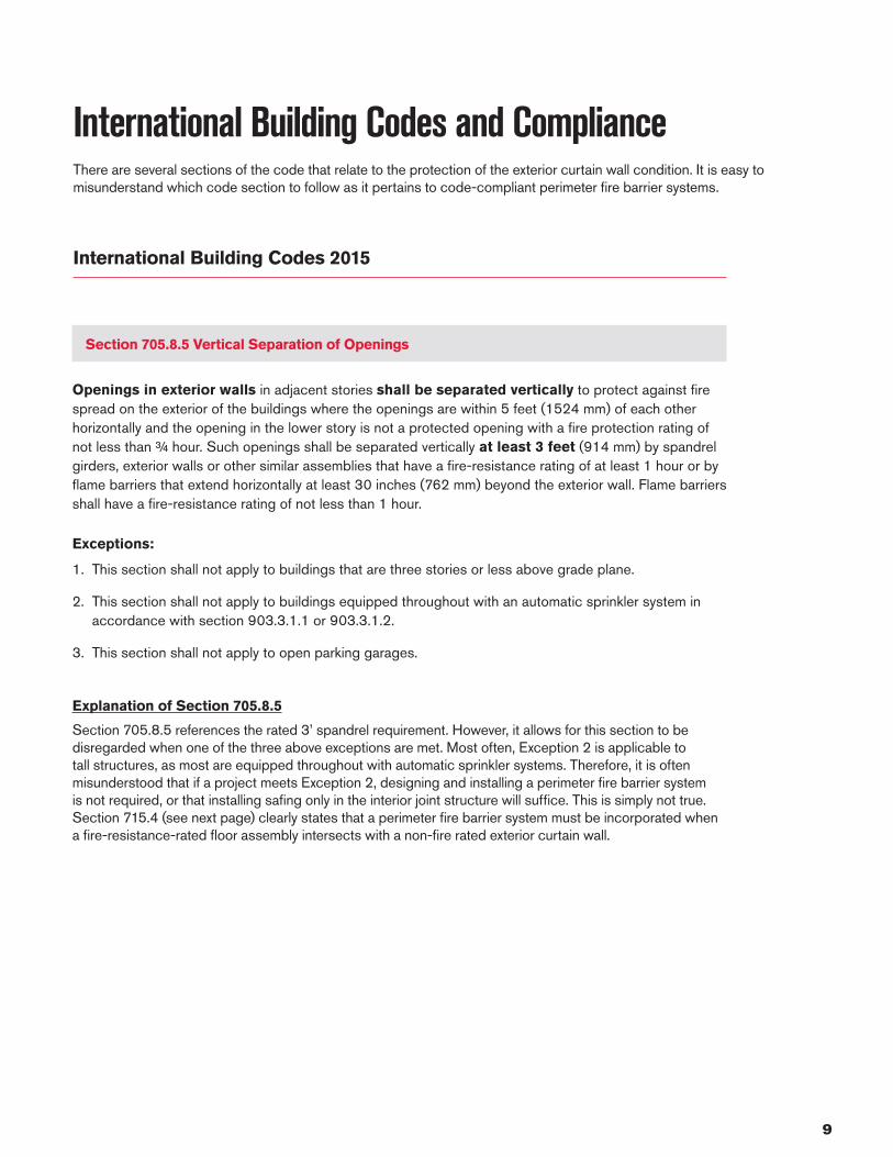
Steel-framed Curtain Wall System
5
7
6
4
31
2

15
Thermafiber® FireSpan® 90 Mineral wool insulation
• Thermafiber® FireSpan® 90 Mineral wool is friction-fit for full cavity depth between steel framing.
Thermafiber® RainBarrier® 45 or HD Mineral wool continuous insulation
Air and water barrier
Installation of Thermafiber® Safing insulation by compression fit
• A reinforcing mounting angle from the floor edge to the stud framing in should be installed in the safing area.
• The stiffener, in conjunction, with the angled steel strut also reinforces the studs against bowing during fire exposure and insures the compression of the mineral wool safing will be secure.
• A minimum 25% compression fit is recommended to create a tight seal that maintains integrity, preventing flame and hot gases from breaching through to the floor above.
1 5
6
7
2
3
4
Approved smoke sealant
• Applied to the top of the safing insulation to make the system smoke-tight.
• The smoke sealant is ommonly spray-applied to the top of the safing insulation.
• A ½" overspray is usually specified to extend the smoke seal onto the floor slab on one side and the gypsum board surface on the other, creating a continuous seal that impedes passage of smoke.
• See Specific UL or Intertek design for approved smoke sealants.
Mortar droppings collection device
Densglass® gypsum board
Densglass is a registered trademark of Georgia-Pacific Gypsum LLC.

16
Most Common Perimeter Fire Barrier Systems (Top 5)Thermafiber, Inc. has identified trends in perimeter exterior wall designs, and has developed and tested fire barrier solutions for these popular designs. These fire barrier solutions are engineered to be code-compliant without compromising design. This is a list of common solutions, in order of most-specified.
• This patented Impasse® system offers a no backer bar design with the extension of the vision glass down to the top of the floor.
• 2-hour F rating
• Fewer mechanical fasteners required vs. traditional systems
• Provides significant labor savings
• No backer/reinforced member required when window sill transom is inline or spaced a maximum of 3″ above the top of floor slab
• This system offers interior back pan protection without the need for additional insulation shelf below the safing.
• 2-hour F and Integrity rating
• Does not require stitch-welding the T-bar to the steel back pan
• No mullion cover required above the floor slab
1
2
Thermafiber® Impasse® No Backer Bar™ Aluminum-Framed Curtain Wall Perimeter Fire Barrier System
Thermafiber® Aluminum-Framed Curtain Wall Perimeter Fire Barrier System with Galvanized Steel Back Pan

17
• This patented Impasse® system offers a solution for providing necessary backer reinforcement in assemblies where the floor slab is located mid-spandrel height.
• 2-hour F rating
• Fewer mechanical fasteners required vs. traditional systems
• This patented Impasse® system eliminates the labor-intensive installation of a mechanical backer reinforcement member by utilizing a rigid mineral wool Thermafiber®
FireLedge® component to support the compressed Thermafiber®
Safing insulation and provide a secure fire barrier at the interior joint.
• 2-hour F rating and 3-hour F rating
• This system offers a solution for a steel stud exterior wall that bypasses the rated floor assembly.
• 2-hour F and Integrity rating
3
4
5
Thermafiber® Impasse® Aluminum-Framed Curtain Wall Perimeter Fire Barrier System
Thermafiber® Impasse® No Backer Bar™ with FireLedge® Aluminum-Framed Curtain Wall Perimeter Fire Barrier System
Thermafiber® Steel-Framed Curtain Wall Perimeter Fire Barrier System

18
Smoke SealantsSince smoke inhalation is responsible for the majority of fire-related deaths, most perimeter fire barrier systems tested at UL evaluate the air leakage rate through the interior joint. The air leakage is rated in CFM per foot at both ambient and at 400°F.
To help control smoke passage through the interior joint, an approved smoke sealant is applied over top of the safing insulation. The function of a smoke sealant is to impede passage of toxic smoke. It is always applied on the non-fire-exposed side of the perimeter fire barrier system.
Smoke sealants are typically an elastometric, spray-applied material that extends onto the curtain wall insulation and floor assembly to form a barrier against the leakage of smoke through the safe-off joint.
Approved smoke sealant manufacturers are specifically listed in the UL or Intertek perimeter fire barrier system listings.

19
Spandrel RequirementsThe perimeter fire barrier system must address the particular spandrel material. A system designed for one type of spandrel material can’t be utilized for addressing the fire protection of another type of spandrel material.
Here are additional requirements to know:
• A specific amount of spandrel protection is required below the safe-off area. This detail is required to preserve a portion of the exterior wall so that safing remains securely in place
• Additional reinforcement and mechanical attachment is required for shorter spandrels.
• Composite panels and spandrel material used must be evaluated per ASTM E2307 or NFPA 285 for non-combustibility. Untested components of the spandrel assembly could cause a potential failure during a fire event.
• Safing insulation must be installed up to a steel back pan with reinforcement. If a steel back pan is used, proper reinforcement and mechanical attachment of the curtain wall insulation is required.
• A one-inch air space is required between the curtain wall insulation and the interior face of the spandrel glass.
• Additional curtain wall insulation can be added to the spandrel area to improve the overall thermal performance of the assembly. If this is the case, re-evaluation of the mechanical attachment and support of the spandrel insulation that serves as the primary fire barrier is required.

20
Special ConditionsWe recognize there are situations where there are special conditions to consider while designing and installing perimeter fire barrier systems. The following considerations have to be incorporated in the design in order for the perimeter fire barrier system to perform to the stated hourly fire rating.
Short spandrel heights
• Shortest spandrel tested and listed is 10".
• Minimum exposed spandrel below floor slab is 5.5".
• Significant steel reinforcement is required.
• 20-ga. steel perimeter frame with mineral wool curtain wall insulation attached every 8" on center (oc) to the steel angle.
• Horizontal 3" 20-ga. steel T-bar in front of curtain wall insulation.
• 20-ga. continuous 1"x1.5" angle between the curtain wall insulation and safing.
• Mechanical attachment of curtain wall insulation to perimeter frame should be at 8" frequency by pin method.
Wider spandrel conditions
• There is no current method of evaluating this condition since there is a limitation with the test apparatus in ASTM E2307.
• Anything wider than 72" on curtain wall center requires further evaluation since there are manufacturing limitations on width of insulation.
• Most systems do not allow for vertical seam; of the few assemblies that allow for them, additional considerations are required:
– 4” thick or greater Thermafiber® FireSpan® 90 or 40 curtain wall insulation
– All are hat channel designs with multiple horizontal steel structural members
• Considerations for a vertical seam:
– Unsupported vertical seams in the curtain wall insulation can open up during a fire, where insulation shrinkage can occur.
– Since seams continue to open up through the interior joint behind the safing insulation, this allows for fire to pass through the safing line.
– No framing member for mechanical attachment
• Wider spandrel conditions are evaluated with recommendations provided by the Thermafiber Insolutions® team on a project-by-project basis.
• UL-approved solutions are available from Thermafiber, Inc.

21
Curtain Wall Insulation covers and protects steel back pan to minimize oil canning
Safing insulation installed between the curtain wall insulation and slab edge.
Steel back pans
Steel back pans are becoming quite common because of the popularity of unitized systems. The steel back pan is installed as the vapor barrier to the system, but these systems can have issues if not properly protected. Even though steel does not melt when exposed to heat, the pan will “oil can” (buckle), creating peaks and valleys due to the expansion and contraction of the panel when exposed to high temperatures during a fire. Unfortunately, the safing insulation cannot conform to those peaks and valleys. Small seams form at the safing line which allows flame and hot gases to propagate to the next floor. There are specific UL or Intertek systems that address the protection of these systems. These can be found in the UL or Intertek Fire Resistance Directory.
This depiction shows how improperly installed steel back pan assemblies perform when exposed to the fire conditions of ASTM E2307.
This system shows mineral wool covering and protecting the steel back pan to keep it from warping.
Steel back pan
Basic steel back pan with spandrel insulation on the inside of the back pan
22
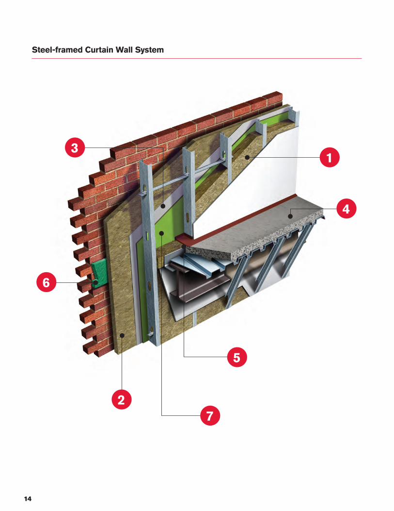
Mineral wool installed outside of back pan
Thermafiber® FireSpan® 90 Safing shelf installed to steel back pan. Safing shelf moves with steel back pan to cover and protect any seams forming between interface of steel back pan and Thermafiber® Safing insulation.
Steel back pan with spandel insulation to the outside of the back pan
Steel back pan
This system shows a Thermafiber® FireSpan® 90 safing shelf, mechanically attached to the face of the steel panel. This shelf covers the seam between the interior face of the back pan and the safing. If peaks and valleys occur, the seam is covered by the safing shelf. Note: This assembly does not require stitch-welding the T-bar to the steel back pan and no mullion cover is required above the floor slab.
Steel back pan

23
Curved spandrel walls
• There is no tested or listed assembly for curved curtain walls.
• Conformance of spandrel insulation to the arc depends on degree of radius.
• Limited mechanical attachment options are available.
• High cost custom mechanical fasteners are typically required.
• Custom support members:
• Radius backer reinforcement is required in front of the spandrel insulation with same arc as the slab.
• Accommodations are required where there are varied joint widths between slab and spandrel insulation.
• Curved spandrel conditions are evaluated with recommendations provided by the Thermafiber Insolutions® team on a project-by-project basis
Thermafiber® FireSpan® 90 Safing Curtain wall spandrel insulation
Thermafiber® FireSpan® 90 Safing Mullion cover protection
Curtain spandrel wall

24
• There is no tested or listed assembly for angular curtain walls.
• Limited mechanical attachment options are available.
• High cost custom mechanical fasteners required.
• Custom support members are often required.
• Considerations include:
• Securing the safing insulation in the linear joint
• Flame impingement: more fire exposure to spandrel when angling out
• Varying linear joint widths create difficulty in achieving safing compression requirements.
— May require mechanical attachment to keep the safing insulation from dislodging over lifetime of the building.
• Angled spandrel conditions are evaluated with recommendations provided by the Thermafiber Insolutions® team on a project-by-project basis
Thermafiber® Safing Insulation
Additional mechanical support
Angled spandrel walls
Angled spandrel wall

25
Exposed curtain wall anchors at the floor line
• The UL Fire Resistance Directory states: “Curtain wall spandrel panel dead load anchors located below the concrete floor should be protected from direct fire exposure.”
• Unprotected curtain wall anchors exposed below the floor line create a higher probability of complete system failure.
• UL has created a new category (XHDI) for perimeter fire barrier accessories, which includes an anchor protection component.
Combustible Building Materials Used in Perimeter Fire Barrier SystemsRequirements for exterior walls containing combustible materials in the IBC
Material Code Section
Foam plastic insulation 2603.5
Metal composite materials (MCM) 1407.10
Fiber-reinforced polymers 2612.6
High-pressure laminates (HPL) 1409.10
Water-resistive barrier 1403.5
Exposed curtain wall anchors at the floor line protected by mineral wool insulation. Thermafiber® recommends a minimum 4" thickness of Firespan® 90, 40 or Safing Insulation be mechanically attached to cover and protect exposed curtain wall anchors and attachment points at vertical mullions
Safing
Safing shelf
Curtain wall insulation
Considerations:
• Provide additional fuel load under fire conditions
• Untested exterior facade panels
• Unknown panel performance when exposed to ASTM E2307 conditions
• Should be NFPA 285 compliant, at the very least
• Should be attached independent from the perimeter fire barrier system
• Should not provide structural support of the perimeter fire barrier system
• Other untested building materials
• Materials with known fuel sources should not be installed to perimeter fire barrier assemblies to achieve targeted thermal values

26
Engineering JudgmentsInternational Firestop Council (IFC)
New: February, 2007 1
RECOMMENDED IFC GUIDELINES FOR EVALUATING FIRESTOP SYSTEMS IN ENGINEERING JUDGEMENTS (EJ’s)
PERIMETER FIRE BARRIER SYSTEMS
The International Firestop Council, IFC, is a not-for-profit association of manufacturers and users of fire protective materials and systems. IFC’s mission is to promote the technology of fire containment in modern building construction through research, education programs, and the development of safety standards and code provisions. These recommended guidelines are presented as part of the IFC’s educational information program. They are for informational and educational purposes.
THE PREMISE OF FIRESTOP SYSTEMS
Perimeter Fire Barrier systems protect against the passage of fire, hot gasses and toxic smoke through the void between the floor slab edge and the curtain wall.
These systems are required by building codes to be tested and rated as part of an assembly in accordance with ASTM E 2307, Standard Test Method for Determining Fire Resistance of Perimeter Fire Barrier Systems Using Intermediate-Scale, Multi-Story Test Apparatus, or with an approved material capable of preventing the passage of flame and hot gases sufficient to ignite cotton waste when subject to ASTM E119 time-temperature conditions under a positive pressure differential of 0.01 inch water column.
All elements of a tested and rated perimeter fire barrier system, including the assembly into which the system is installed, constitute a specific and inseparable engineered unit that must be utilized as such. These systems (designs) are tested and listed by independent testing agencies and the specific elements of each design become a part of the listing and a necessity for the performance of the system.
When field conditions differ from original design or unanticipated construction hindrances are encountered, Engineering Judgments (EJ’s) are typically made that recommend alternative methods to ensure performance of the firestop system is not compromised. Generally these conditions or hindrances cannot be easily or cost-effectively redesigned so alternative protection schemes must be implemented to maintain the system’s integrity. Since these recommendations are not based upon identical designs as that which were fire tested, it is important that they be developed using sound engineering principles and good judgment.
Construction industry professionals, building officials, fire officials, firestop contractors and other stakeholders need appropriate guidelines for evaluating and using such judgments. As such, the IFC developed Recommended IFC Guidelines for Evaluating Firestop Systems in Engineering Judgments – Perimeter Fire Barrier Systems.

27
The Critical Components of Engineering Judgments for Perimeter Fire ContainmentThermafiber, Inc. has identified the following critical components when providing a quality engineering judgment for perimeter barrier systems:
1. The engineering judgment must be project-specific and represent the project conditions being evaluated.
2. At least one third party tested system (evaluated to ASTM E2307 or appropriate standard based on requirement of the applicable jurisdiction) that most closely represents the project construction details must be referenced as the basis of design in order to properly evaluate the hourly F rating.
3. Engineering judgments must provide a complete description of the critical elements of the system and must include the tested and listed system's design criteria that are required to make the system work. The engineering judgment must be based on interpolation of previously tested perimeter fire barrier systems that are similar to the conditions upon which the judgment is given.
4. An engineering judgment should not be used as a way to circumvent testing new fire barrier assemblies. Engineering judgments that do not have data to interpolate and/or extrapolate, within the boundaries of good design practices of the condition in question, should initiate the need for fire testing.
5. An engineering judgment must state that it is such and not a tested and listed system.
6. It is important to understand that although it is the joint between the slab edge and curtain wall that is evaluated during testing, the surrounding construction components and insulation of the system is also important in ensuring acceptable joint performance.
In addition to the critical components of engineering judgments highlighted above, Thermafiber strongly abides by the International Firestop Council (IFC)-provided recommendations on writing engineering judgments, titled “Recommended IFC Guidelines for Evaluating Firestop Systems in Engineering Judgments.” Below is an outline of several of the requirements (not all included here) for engineering judgments:
• All elements of a tested and rated firestop system, including the assembly into which the system is installed, constitutes a specific and inseparable engineered unit that must be utilized as such. Firestop system designs are tested and listed by independent testing agencies such as UL® and Intertek. The specific elements of each design become integral to the listing.
• According to the IFC, engineering judgments should be based upon interpolation of previously tested firestop systems that are either sufficiently similar in nature or clearly bracket the conditions upon which the judgment is to be given.
• Engineering judgments should be limited only to specific conditions and configurations upon which the engineering judgment was rendered and should be based upon reasonable performance expectations for the recommended firestop system under those conditions.
For more information, reference http://www.firestop.org > http://www.firestop.org/uploads/2/4/5/4/24544763/ifc_engineering_judgment_guidelines_perimeter_fire_barrier_systems.pdf

28
Project Spotlight
SALESFORCE TOWER | San Francisco, CaliforniaAt 1070 feet tall, the 61-story obelisk Salesforce Tower located in San Francisco’s Financial District is now considered the tallest building in California. Completed in early 2018, the $1.1 billion Salesforce Tower is a visually stunning achievement in sustainable design strategy. The Pelli Clarke Pelli Architects design team incorporated the easy-to-install Thermafiber® Impasse® Curtain Wall Perimeter Fire Containment System to streamlines the installation of curtain wall insulation and take full advantage of the fire resistive, enhanced acoustical performance, and vapor barrier properties of Thermafiber® FireSpan® 90 mineral wool insulation and Safing insulations. The Impasse® system is tested and rated with UL® laboratories and provides up to 3* hours of fire containment.
181 FREMONT | San Francisco, CaliforniaDesigned by Heller Manus Architects,181 Fremont is a mixed-use skyscraper located in San Francisco’s Financial District. Standing more than 800 feet tall and 70 stories, 181 Fremont is now considered the tallest residential building on the West Coast and third-tallest building in San Francisco. Targeted to achieve a LEED Platinum certification, the 181 Fremont design incorporates innovative design strategies for sustainability and energy efficiency. The customized Thermafiber® Impasse® solution incorporated Thermafiber® FireSpan® 90 Curtain Wall Insulation and Thermafiber® Safing Fire Containment Insulation for enhanced fire protection in curtain wall and perimeter fire containment.
WILSHIRE GRAND | Los Angeles, CaliforniaLocated in downtown Los Angeles’ Financial District, the 73-story Wilshire Grand tower soars to a height of 1,100 feet making it LA’s tallest skyscraper. Architecture firm AC Martin designed the $1.2 billion structure that earned LEED Gold certification after opening in 2017. The Thermafiber® Impasse® System solution was selected to help streamline the installation of curtain wall insulation and take full advantage of the fire resistive, enhanced acoustical performance, and vapor barrier properties of Thermafiber® FireSpan® 90 mineral wool insulation and Safing insulations.
VIA 57 WEST | New York, New YorkCompleted in 2016, VIA 57 West has earned multiple awards including 2016 Best Tall Building, Americas by the Council on Tall Buildings and Urban Habitat (CTBUH), 2015 Progressive Architecture Citation Award, and 2012 NY AIA Merit Award. The 830,000 sq. ft. high rise residential building features a lush 22,000 sq. ft. European inspired courtyard at the heart of the building. This unique building was design by Bjarke Ingels Group (BIG) architectural firm and includes multiple Thermafiber® solutions including FireSpan® 90 Curtain Wall Insulation, Safing Fire Containment Insulation, RainBarrier® 45 Rain Screen/Cavity Insulation, and SAFB™ (Sound Attenuation Fire Blanket) Insulation.

29
380 MADISON AVE. | New York City, New YorkThe 390 Madison office building, located in the heart of New York City’s Midtown, used Thermafiber® mineral wool insulation, including Thermafiber® FireSpan® 90 and Thermafiber® Safing solutions in the construction of the 25-story, 859,000 square-foot building. Architects Kohn Pedersen Fox Associates (KPF) dramatically transformed the existing tower that was previously known as 380 Madison into a modernized tower with new energy-efficient curtain walls. The redesign earned a Merit Award from the AIA New York 2016 awards and received LEED Gold Certification.
7 BRYANT PARK | New York City, New YorkLocated in Midtown Manhattan, the sleek 30-story glass-and-stainless-steel building was designed by architect Henry N. Cobb of the firm Pei Cobb Freed & Partners. The $150 million 7 Bryant Park project incorporates a unique curtain wall that utilized the Thermafiber® Impasse® System, including Thermafiber® FireSpan® 90 and Thermafiber® Safing, to help save time and money over traditional jobsite installation methods and deliver enhanced fire protection performance in the curtain wall and perimeter fire containment. Due to the minimum of 70 percent recycled content, the Thermafiber® Impasse® System also helped the project achieve LEED certification at the Gold level upon its completion in 2016.
THE STEINWAY TOWER | New York City, New YorkDesigned by SHoP Architects, the 1,400-foot, 82-floor residential tower in New York City has the distinction of being the world’s skinniest skyscraper. Completed in 2018, the project incorporated Thermafiber® FireSpan® 90 Curtain Wall Insulation to provide enhanced fire protection in curtain wall and perimeter fire containment systems. With 70 percent recycled content, Thermafiber® mineral wool insulation also contributed to the overall project sustainable goals of earning LEED CS Gold certification.
1 WORLD TRADE CENTER | New York City, New YorkThe 1 World Trade Center architectural firm Skidmore, Owings and Merrill selected Thermafiber® FireSpan® 90 Curtain Wall Insulation for use in conjunction with Thermafiber® Safing Fire Containment Insulation to achieve outstanding fire protection in curtain wall and perimeter fire containment systems. Additionally, a custom designed Thermafiber® Impasse® Insulation Hanger System was utilized to make installation simple, accurate and fast. This collection of products with a minimum of 70 percent recycled content contributed to overall project sustainable goals and earning LEED Gold certification.

30
Notes

31
Notes

To learn more about Thermafiber Insolutions®
services or consultation visit www.thermafiber.com.
Pub. No. 10022722. Printed in U.S.A. March 2018. © 2018 Owens Corning. All Rights Reserved. © 2018 Thermafiber, Inc. All Rights Reserved.
THERMAFIBER® and THERMAFIBER INSOLUTIONS® are registered trademarks of Thermafiber, Inc.THE PINK PANTHER™ & © 1964-2018 Metro-Goldwyn-Mayer Studios Inc. All rights reserved. Other trademarks are the properties of their respective owners.
References1 “About the U.S. Fire Administration.” www.usfa.feva.gove/bout/index.html2 “USFA Nonresidential Build Fire Trends (2005-2014).” https://www.usfa.fema.gov/downloads/pdf/statistics/nonres_bldg_fire_estimates.pdf3 “USFA Trends in fires, deaths, injuries and dollar loss (2004-2013).” www.usfa.fema.ogv/data/statistics/⁴ ASTM E119-12a, Standard Test Methods for Fire Tests of Building Construction and Materials; ASTM International, 100 Barr Harbor Drive, PO Box C700, West Conshohocken, PA, 19428-2959⁵ ASTM E2307, Standard Test Method for Determining Fire Resistance of Perimeter Fire Barrier Systems Using Intermediate-Scale, Multi-story Test Apparatus; ASTM International, 100 Barr Harbor Drive, PO Box C700, West Conshohocken, PA, 19428-2959
THERMAFIBER INC. ONE OWENS CORNING PARKWAY TOLEDO, OHIO, USA 43659888-TFIBER1 [834-2371]www.thermafiber.com