Embed Size (px)
Citation preview

Fire Technology manuscript No.(will be inserted by the editor)
Design of an ASTM E119 fire environment in a largecompartment?
Chao Zhang · William Grosshandler · AnaSauca · Lisa Choe
Received: date / Accepted: date
? Cite this paper as: Zhang, C., Grosshandler, W., Sauca, A., Choe, L.. Fire Technol (2019).https://doi.org/10.1007/s10694-019-00924-7
C. ZhangNational Institute of Standards and Technology, Fire Research Division, USACorresponding author. E-mail: [email protected]. GrosshandlerNational Institute of Standards and Technology, Fire Research Division, USAA. SaucaNational Institute of Standards and Technology, Fire Research Division, USAL. ChoeNational Institute of Standards and Technology, Fire Research Division, USA

2 Chao Zhang et al.
Abstract Structural fire protection design in the United States is based on pre-1
scriptive fire-resistance ratings of individual load-bearing elements which are de-2
rived from standard fire testing, e.g. ASTM E119. In standard fire testing, a3
custom-built gas furnace is traditionally used to heat a test specimen by follow-4
ing the gas temperature-time curve prescribed in the ASTM E119 standard. The5
span length of the test specimen seldom exceeds 6 m due to the size limitations of6
available furnaces. Further, the test specimen does not incorporate realistic struc-7
tural continuity. This paper presents a basis for designing an ASTM E119 fire8
environment in a large compartment of about 10 m wide, 7 m deep and 3.8 m high9
constructed in the National Fire Research Laboratory of the National Institute of10
Standards and Technology. Using the designed fire parameters, a full-scale exper-11
iment was carried out on December 20, 2018. The measured average upper layer12
gas temperature curve was consistent with the E119 fire curve. The maximum dif-13
ference between the measured curve and the E119 fire curve towards the end of the14
test was about 70 ◦C (7%). The study indicates that by proper design and control,15
the time-temperature curve for the standard fire testing may be approximated in a16
real compartment. The experimental method suggested in this paper would allow17
to extend the application of the standard fire testing to large-scale structures not18
limited by the size of furnaces, to experimentally evaluate the thermally-induced19
failure mechanism of structural systems including connections and frames, and to20
advance fire protection design methods.21
Keywords Full-scale experiment · ASTM E119 fire · Large compartment · Test22
fire · Design approach23
1 Introduction24
From 1917 to 1920, the National Board of Fire Underwriters, Underwriters Labo-25
ratory, Factory Mutual companies, and the National Bureau of Standards (NBS,26
now the National Institute of Standards and Technology, NIST) worked together27
and conducted the first standardized fire tests on columns1. More than 100 columns28
made of steel, cast iron, reinforced concrete, and timber were tested [1]. Simon H.29
Ingberg of NBS was in charge of this program, which resulted in the establishment30
of the fire resistance rating method or standard fire test method in 1918 [2]. In 1928,31
Ingberg published “Tests of the severity of building fires” [3] in which the concept32
of equivalent fire severity was originally proposed. By that concept, the severity of33
a realistic fire was assessed based on the area under the time-temperature curve34
and, therefore, could be quantified by the duration in a standard fire exposure35
(fire resistance rating). Although the area under a fire curve does not account36
for the time-dependent interaction between the thermal load and the structural37
response, Ingberg’s development of the concept of equivalent fire severity was re-38
garded as a major milestone in the modern discipline of fire safety engineering [4].39
The concept of equivalent fire severity is the basis for the fire resistance rating40
method or standard fire test method used in current codes. After Ingberg, alter-41
native approaches were developed, e.g. [5–7], intending to calculate the equivalent42
fire severity in a more rational way. However, none of these approaches has been43
1 Note that the first known publication of the standard fire curve is NFPA Quarterly, Vol.9 (1916), pp. 253-260.

Design of an ASTM E119 fire environment in a large compartment? 3
generally accepted, mostly because of their inability to account for the behavior of44
structures in realistic fires. The lack of connection between fire resistance rating45
and the actual behavior of structures in fire remains a challenging problem in the46
field of fire protection research.47
The fire resistance rating method has dominated fire protection design practice48
and has remained almost unchanged over the past 100 years [8]. The method is49
regarded as easily implementable, controllable and reproducible, while both acci-50
dental fires (e.g. the Broadgate Phase 8 fire [9]) and realistic fire tests (e.g. the51
Cardington full-scale fire tests [10]) have demonstrated that the method cannot52
adequately assess the actual level of safety of a structure exposed to fire. The53
limitations of the standard fire test method have been generally recognized and54
usually include the following critiques [11]: (1) the standard fire curve is not repre-55
sentative of a realistic fire in a real building. A realistic fire includes both heating56
and cooling phases while the standard fire does not decrease with time. Also, the57
standard fire represents a uniform heating condition while the heating condition in58
a realistic fire is typically non-uniform; and (2) the tested isolated members in the59
furnace seldom represent the behavior of the components in an entire structure. In60
a real building, a component is restrained by the surrounding structures. The re-61
straints induce stress in the heated component and might also activate alternative62
load-bearing modes (e.g., membrane action of a composite floor slab [12], catenary63
action of restrained beams [13]). Furthermore, there exist alternative load paths64
in entire structures [14].65
Over the past few decades, especially after the Cardington full-scale fire tests [10],66
a large amount of effort has been devoted to research on performance-based meth-67
ods for fire protection design. Most work has been conducted in furnaces using the68
standard fire curve or other user-defined fire curves [15–21], while compartment69
fire tests [8,22] and open burning/heating tests [23,24] have also been conducted.70
Furthermore, collapses of buildings in actual fires (e.g. the World Trade Center [25]71
and the Faculty of Architecture Building at Delft University of Technology [26])72
present that structural performance in realistic fires is deemed more complex than73
those observed in furnace tests. For situations where the effect of fire induced74
thermal gradient is significant, fire protection design based on the furnace tests75
might not be conservative [27–30]. Therefore, testing structures in realistic fires76
becomes a priority in moving towards structural fire engineering design [31], and77
the development of novel fire testing methods has become an important research78
topic [32–34]. A notable achievement of realistic fire testing is the construction of79
a unique facility: the National Fire Research Laboratory (NFRL) at the National80
Institute of Standards and Technology [35]. The NFRL currently is the only facility81
in the United States that allows research on the response of real-scale structural82
systems to a realistic fire simultaneously with mechanical loading under precisely83
controlled laboratory conditions.84
A significant need still exists for a fuller understanding of the failure mecha-85
nisms of structural systems in fire and for advancement of current design methods,86
both prescriptive and performance-based. Since standard fire testing was first in-87
troduced, structural testing techniques, computational modeling and fire safety88
science have evolved, allowing the high-fidelity modeling and testing of the perfor-89
mance of structural systems in realistic fires. With the unique facilities such as the90
NFRL and by interdisciplinary research collaborations, reliable experimental and91
numerical data can be produced for advancing design methods. In celebration of92

4 Chao Zhang et al.
the 100th anniversary of the establishment of the standard fire testing methods,93
e.g., the China-US Workshop on Building Fire Safety (held on May 15, 2017 in94
Beijing) [36] and the ASTM Workshop on Advancements in Evaluating the Fire95
Resistance of Structures (held on December 6-7, 2018 in Washington DC) [37],96
the capability of producing the standard fire time-temperature curve outside of a97
furnace, which is presented in this paper, provides an important step forward to98
help relate standard furnace test results to structure performance in a real fire and99
to advance fire protection engineering.100
2 Background101
NIST hosted three stakeholder workshops [31, 38, 39] to prioritize the needs of102
structural-fire experimental research. Based on the workshops’ recommendations,103
composite floor systems were selected for study because of their widespread use in104
building construction and because of modeling challenges in such systems exposed105
to a fire. Long-span steel-concrete composite beams were tested in the first phase106
of the program. The results of these simulations and experiments are documented107
in [40]. The current paper deals with designing test fires for a 10 m by 7 m steel-108
concrete composite floor.109
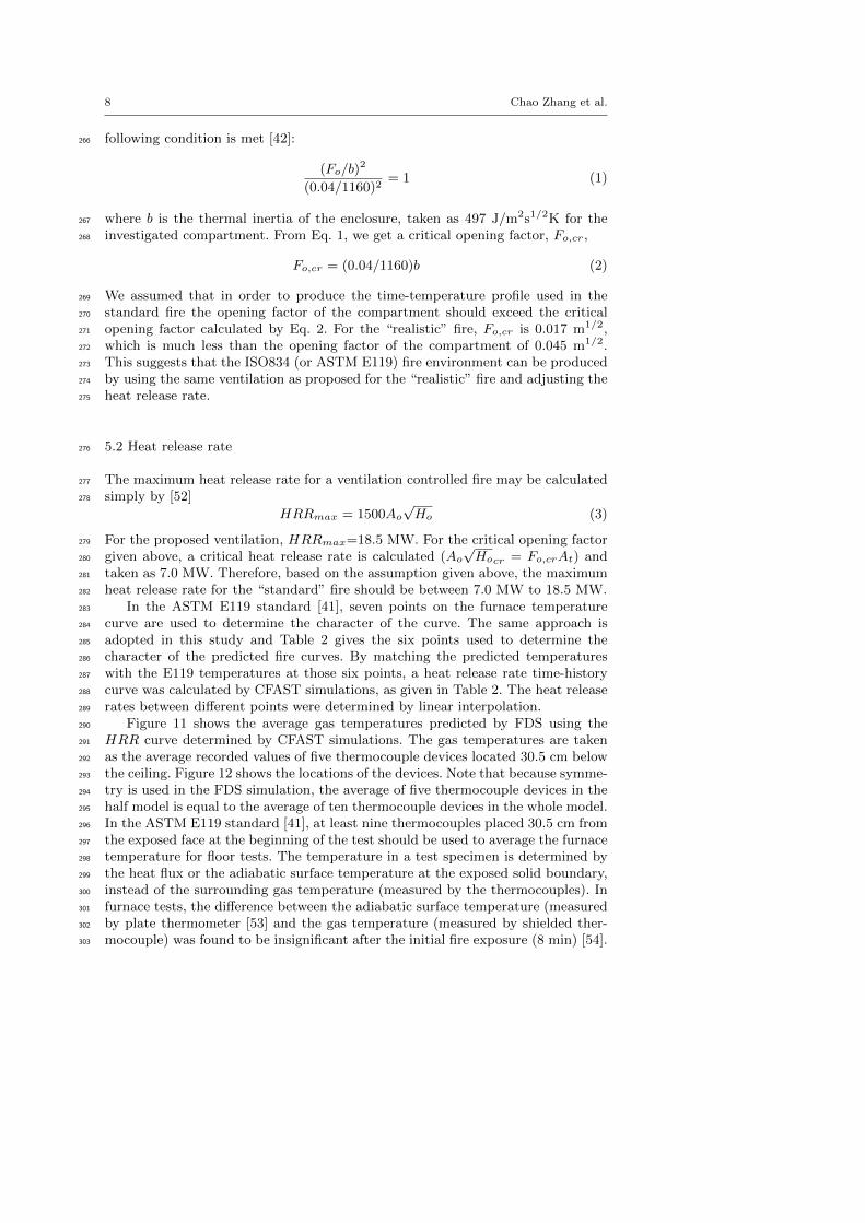
The test frame for this study is a two-story, two bay by three bay gravity110
frame, as shown in Figure 1. The test bay is 6.1 m by 9.1 m. The test bay will111
be loaded mechanically using hydraulic actuators to simulate the gravity service112
load condition. For this series of composite floor tests, the columns will not play113
a role in floor failure; rather, the columns will be protected so that they provide a114
reliable load path.115
3 Design objective and procedure116
Two test fires will be used, a “realistic” fire and a “standard” fire. The “realistic”117
fire is intended to represent an extreme but plausible fire, one that has the potential118
to threaten the structure. This fire will be confined within a single compartment,119
allowing flame leakage through openings with restricted sizes and locations. The120
“standard” fire will be controlled to provide uniform average upper layer gas tem-121
peratures that follow the time-temperature curve specified in the ASTM E119122
standard [41]. Other conditions of the standard furnace test (e.g. pressure, heat123
flux distribution) are not replicated in this “standard” fire test. The results of124
the “realistic” fire tests will elucidate the failure modes of the floor system in a125
realistically restrained structural steel frame. The results from the “standard” fire126
tests will allow one to relate the behavior of a full-scale composite floor system127
to its rating provided by ASTM E119, as well as the behavior at times extended128
beyond its rating.129
Figure 2 shows a general procedure for designing a test fire in which the tem-130
perature of an exposed steel member reaches a target temperature. The design131
procedure is initiated by specifying compartment geometry and boundary prop-132
erties, beam specimen dimensions, insulation thickness and properties, and target133
steel temperature. We endeavor to solve for the heat release rate (and the size134

Design of an ASTM E119 fire environment in a large compartment? 5
and distribution of the burners) and opening condition (size, geometry and loca-135
tion). First, initial values of heat release rate (HRR) and opening factor (Fo) are136
assumed based on literature survey. Second, simple empirical equations (e.g. para-137
metric fire model [42] and a one-dimensional (1D) heat conduction model [43]) are138
used to calculate the gas and steel temperatures. If the calculated maximum steel139
temperature is less than the target value, the HRR and Fo are modified, as neces-140
sary. Third, a zone model and two-dimensional (2D) heat conduction analyses are141
used to check and refine the HRR and Fo from the previous step. Finally, a field142
fire model and three-dimensional (3D) heat conduction simulation are carried out143
to check and refine the HRR and Fo, and to optimize the size and location of the144
fire and vents.145
The procedure outlined in Figure 2 was used previously to design the test146
fire for structural experiments on a 6 m long steel W-shape beam during the147
commissioning of the NFRL [34]. In this study, only the average gas temperature148
in the compartment was considered and therefore the heat conduction analyses for149
the exposed members was not be performed.150
4 Design of the “realistic” fire151
4.1 Fire load152
The heat release rate for the “realistic” fire is based upon knowledge gained in153
previous full-scale experiments, one conducted at NIST using three workstations154
as the fuel [44], and another at Cardington using wood pallets for fuel [45].155
The previous full-scale fires at NIST [44] were conducted in a room that was156
10.81 m deep, 7.02 m wide, and 3.36 m high. The room was fully enclosed except157
for windows along one of the 7.02 m walls, providing a total area of 4.77 m2158
for ventilation. Two experiments (test 1 and test 2 in [44]) were run using three159
identical workstations with a total combustible mass of 1670 kg (17 MJ/kg). The160
test at Cardington [45] was conducted in an eight-story steel structure. The fire161
room in Test 7 was 11.0 m wide by 7.0 m deep and one story (4.1 m) high. A single162
vent of 1.27 m high and 9 m wide was used. Wood cribs uniformly distributed163
across the floor were used as the fuel, providing 40 kg/m2 mass load on the fire164
floor (700 MJ/m2 energy load).165
For the current experimental series, the fire compartment is about 10 m wide,166
7 m deep and 3.8 m high, as shown in Figures 3 and 4. Four natural gas burners167
each 1.0 m by 1.5 m provide the fire source. Natural gas is used since: (a) a168
gaseous fuel allows independent and near-instantaneous control of HRR during169
an experiment; (b) the NFRL has extensive experience with high accuracy flow170
rate measurements and independent means of HRR calculation when using natural171
gas; (c) the major constituent of natural gas (CH4) has the lowest tendency to soot172
of any hydrocarbon, providing a favorable environment for optical measurements173
of displacement; (d) natural gas fires are well-suited for simulation; and (e) natural174
gas provides a baseline for comparison to future solid fuel fires.175
Surveys [46] have found that the fuel loads in commercial and public spaces176
vary greatly with the designated purpose of the space. A standard office contains177
in the range of 420 to 655 MJ/m2 of combustible material; a shopping center178
is in the range of 600 to 936 MJ/m2; and a library can have fuel loads up to179

6 Chao Zhang et al.
2340 MJ/m2. The previous NIST experiment [44] with a fuel load of 400 MJ/m2180
was conducted with only three workstations in a space that more typically would181
have had six workstations. In such a case the energy content would have been 800182
MJ/m2, about equal to the fuel load in the Cardington tests [45] and a bit above183
the survey levels for typical office layouts. Because the “realistic” fire represents184
an extreme fire condition, an equivalent fuel load of 1.6 times the energy content185
more typical of a modern office, or about 1200 MJ/m2 was proposed to simulate186
uncontrolled burning of building contents.187
The right-hand vertical scale of Figure 5 shows the HRR for the “realistic” fire,188
which linearly ramps up to 10,000 kW in 15 minutes, is held steady until 105 min,189
and then is reduced linearly to zero over the next 85 minutes. The HRR determined190
by the concept given by Vassart et al. [46] is also presented for comparison purpose.191
The peak intensity of the fire on a volumetric basis is 37.9 kW/m3, close to that192
in the previous NIST studies [44].193
4.2 Opening factor194
The “realistic” fire is designed to maximize the upper layer temperature, to mini-195
mize the level of smoke, and to avoid excess fuel feeding a fire external to the bay.196
The ventilation is controlled by the total opening area, Ao, and the height of the197
opening, Ho. In wood crib fueled compartment fires, when AoH1/2o is greater than198
10 m5/2, an over-ventilated condition exists [47]. Table 1 gives the key fire param-199
eters for the previous NIST and the Cardington fire tests. W , D and H are width,200
depth and height of the compartment, respectively; Wo is width of the opening; V201
is volume of compartment; Af and At are areas of floor and internal compartment202
boundaries (including openings), respectively; Fo = AoHo1/2At
−1 is opening fac-203
tor; qf is fire load density (per unit floor area); and Tg is gas temperature. It204
appears that the fire in the Cardington test may have been over-ventilated, while205
the fire in the NIST 2008 study was under-ventilated.206
Table 1 also gives the key fire parameters for the proposed “realistic” fire.207
When scaled with the room volume, the opening area is similar to the opening208
area/volume used in the over-ventilated Cardington fire. The value of AoH1/2o for209
the “realistic” fire suggests that this fire would be over-ventilated; however, the210
correlation for wood crib fires is not directly applicable to natural gas fires.211
Figure 5 shows the predicted gas temperature for the proposed “realistic” fire212
using the parametric fire model given in the eurocode 1 (EC1) [42]. The pre-213
dicted peak gas temperature is 1269 ◦C, significantly higher than the measured214
(average) gas temperature in the previous NIST [44] and Cardington tests [45] as215
listed in Table 1. Following the design procedure given in Figure 2, calculations216
using the zone model CFAST (Consolidated Model of Fire Growth and Smoke217
Transport) [48] were run to check the proposed HRR and opening factor. Cal-218
culations based on CFAST show that the proposed HRR and opening factor are219
sufficient to substantially exceed the minimum target temperature of 1000 ◦C, as220
shown in Figure 6. Figure 6 also shows that the opening configuration (location221
and distribution) has modest effect on the upper layer gas temperature and the222
layer height (i.e., the distance from the bottom of hot gas layer to the floor). The223
differences among the predicted peak temperatures are within 110 ◦C (8%) for224
the investigated cases. The authors are aware that zone models are incapable of225

Design of an ASTM E119 fire environment in a large compartment? 7
considering effects of the opening configuration; however, zone model calculations226
still provide valuable information for the initial design of the openings for the fire227
compartment.228
4.3 Fire confinement229
Numerical simulations using the field fire model FDS (Fire Dynamics Simula-230
tor) [49] were run to study the three-dimensional fire dynamics and to identify231
the distribution of openings and burners for the “realistic” fire that confine the232
majority of the heat release to within the compartment. The heat release rate vs.233
time as proposed in Figure 5 is used for all of these simulations. The main opening234
in the south wall is 6 m wide and 1.5 m high and remains constant in size for235
all of the geometries examined, although height of the window sill is varied. The236
size and location of the opening on the opposite (north) wall, and the number and237
distribution of the burners are varied.238
For the compartments with a proposed opening factor of 0.045 m1/2, the FDS239
simulations show that the fires are over-ventilated and the heat release is confined240
primarily to within the compartment. Figure 7 shows how the position and size of241
the north vent significantly affects the simulated flame behavior. Figure 8 shows242
the velocity vectors on a vertical slice through the vents of the compartment with243
the main opening on the south wall 1 m high above the floor, a slit on the north244
wall 6 m wide, 0.3 m high and sill 1 m above the floor, and four burners distributed245
as indicated in Figure 3. The air flow is entirely inward through the opening on the246
north wall. Note that the steel members (steel beams supporting the compartment247
ceiling slab as shown in Figure 3) are omitted in the FDS models because the heat248
sink effect of the steel members was found to be negligible based on the calculation249
by a modified one zone model [50].250
4.4 Uniform gas temperature distribution251
Figure 9 shows the FDS predicted temperature distributions for the compartment252
with the proposed HRR (produced by four distributed burners as shown in Fig-253
ure 3), and a main opening on the south wall (1 m high above the floor) and an254
opening on the opposite north wall (6 m width, 0.3 m high and 1 m above the floor).255
The horizontal temperature distribution in the gas layer about 30.5 cm below the256
ceiling is quite uniform. Figure 10 shows the FDS predicted gas temperature-time257
curves. The maximum gas temperature reaches 1000 ◦C with the standard de-258
viation among 35 temperature detectors located 30.5 cm below the ceiling of 50259
◦C. Note that there is large temperature gradient in the compartment height, as260
shown in Figure 9.261
5 Design of the “standard” fire262
5.1 Critical opening factor263
The temperature-time curve in the heating phase of the EC1 parametric fire model264
can approximate the standard temperature-time (ISO834 fire [51]) curve if the265
8 Chao Zhang et al.
following condition is met [42]:266
(Fo/b)2
(0.04/1160)2= 1 (1)
where b is the thermal inertia of the enclosure, taken as 497 J/m2s1/2K for the267
investigated compartment. From Eq. 1, we get a critical opening factor, Fo,cr,268
Fo,cr = (0.04/1160)b (2)
We assumed that in order to produce the time-temperature profile used in the269
standard fire the opening factor of the compartment should exceed the critical270
opening factor calculated by Eq. 2. For the “realistic” fire, Fo,cr is 0.017 m1/2,271
which is much less than the opening factor of the compartment of 0.045 m1/2.272
This suggests that the ISO834 (or ASTM E119) fire environment can be produced273
by using the same ventilation as proposed for the “realistic” fire and adjusting the274
heat release rate.275
5.2 Heat release rate276
The maximum heat release rate for a ventilation controlled fire may be calculated277
simply by [52]278
HRRmax = 1500Ao
√Ho (3)
For the proposed ventilation, HRRmax=18.5 MW. For the critical opening factor279
given above, a critical heat release rate is calculated (Ao
√Hocr = Fo,crAt) and280
taken as 7.0 MW. Therefore, based on the assumption given above, the maximum281
heat release rate for the “standard” fire should be between 7.0 MW to 18.5 MW.282
In the ASTM E119 standard [41], seven points on the furnace temperature283
curve are used to determine the character of the curve. The same approach is284
adopted in this study and Table 2 gives the six points used to determine the285
character of the predicted fire curves. By matching the predicted temperatures286
with the E119 temperatures at those six points, a heat release rate time-history287
curve was calculated by CFAST simulations, as given in Table 2. The heat release288
rates between different points were determined by linear interpolation.289
Figure 11 shows the average gas temperatures predicted by FDS using the290
HRR curve determined by CFAST simulations. The gas temperatures are taken291
as the average recorded values of five thermocouple devices located 30.5 cm below292
the ceiling. Figure 12 shows the locations of the devices. Note that because symme-293
try is used in the FDS simulation, the average of five thermocouple devices in the294
half model is equal to the average of ten thermocouple devices in the whole model.295
In the ASTM E119 standard [41], at least nine thermocouples placed 30.5 cm from296
the exposed face at the beginning of the test should be used to average the furnace297
temperature for floor tests. The temperature in a test specimen is determined by298
the heat flux or the adiabatic surface temperature at the exposed solid boundary,299
instead of the surrounding gas temperature (measured by the thermocouples). In300
furnace tests, the difference between the adiabatic surface temperature (measured301
by plate thermometer [53] and the gas temperature (measured by shielded ther-302
mocouple) was found to be insignificant after the initial fire exposure (8 min) [54].303

Design of an ASTM E119 fire environment in a large compartment? 9
Although the difference between the adiabatic surface temperature and the gas304
temperature in a realistic fire might be significant [55], the thermocouples are305
used in this study, because the objective of the “standard” fire is to provide the306
fire environment in the ASTM E119 standard [41]. Note that if the objective is307
to provide the ISO 834 fire environment, adiabatic surface temperatures at the308
exposed solids should be considered in FDS calculations since plate thermometers309
are used to control the furnace temperature in the ISO 834 standard [51]. As can310
be seen in Figure 12, using CFAST simulated values of HRR in FDS to calculate311
the average gas temperatures leads to significant under prediction of the E119312
temperatures after the first 5 min.313
The upper curve in Figure 11 shows the average gas temperatures predicted by314
FDS using the HRR values in Table 2. The most appropriate HRR was determined315
through a trial and error process by varying the maximum value within the range316
of 7 MW to 18 MW. The FDS simulations show that the “standard” fire is capable317
of approximating the E119 time-temperature curve. The accuracy of the proposed318
fire parameters (opening, HRR, etc.) is examined in the experimental investigation319
described in the next section.320
6 Experimental investigation321
On December 20, 2018 a fire test was carried out at the NFRL, using the designed322
compartment (and ventilation) shown in Figures 3-4 and the proposed heat release323
rate (and burners) for the “standard” fire predicted by FDS in Figure 11. Twelve324
stainless steel sheathed thermocouples were placed 30.5 cm below the ceiling, as325
shown in Figure 3 and Figure 12. The average of the measured temperatures by326
those thermocouples was used to represent the average upper layer gas temper-327
ature in the compartment. The fire test lasted 80 min. Figure 13 shows the test328
compartment with a view of the fire.329
Figure 14 shows the measured time-temperature curves by the twelve thermo-330
couples. The average gas temperature and the standard deviation are also pre-331
sented. The maximum standard deviation is within 40 ◦C. Figure 15a shows the332
comparison between the measured average gas temperature curve with the E119333
fire curve and Figure 15b shows the measured and proposed heat release rate (of334
the burners). Note that in the test the heat release rate of the burners was ramped335
about 7.5 min after ignition, and, therefore, the zeros of the X-axis in Figure 15a-b336
were shifted by 7.5 minutes. In the first 25 min of the test, the measured aver-337
age gas temperature is slightly lower than the one specified by ASTM E119, due338
mostly to the lower heat release rate in the test in comparison to the proposed339
value, as shown in Figure 15b. The measured average gas temperature exceeds the340
E119 fire curve towards the end of the test, where the measured value exceeds the341
predicted value by 70◦C (7%).342
Post-test simulation using the measured heat release rate was conducted to343
better understand the accuracy of the proposed fire parameters. The whole com-344
partment which includes the steel beams (shown in Figure 3) was modeled in FDS345
with uniform grids of 0.05 m. The FDS input file and the numerical data can be346
found in the FDS Github repository 2. Figure 16 shows good agreement between347
2 https://github.com/firemodels/fds/tree/master/Validation/NIST E119 Compartment.Accessed: 2019-07-29.

10 Chao Zhang et al.
the predicted and measured average upper layer gas temperatures. At tempera-348
tures above about 700 ◦C, FDS under-predicted the average temperatures (within349
60 ◦C), which might be explained by the fact that the downward deformation of350
ceiling was not considered in the FDS numerical model. Note that the zero of the351
X-axis in Figure 16 is defined at 5.75 min after ignition when the measured heat352
release rate of the burners steps to an initial constant value (see the “HRR burner”353
green line ). Figure 17 compares the measured and predicted gas temperatures by354
thermocouples located 30.5 cm beneath the ceiling. FDS predicts lower maximum355
gas temperatures on the north side of the compartment (TC7 to TC12). On the356
south side, FDS predicts lower or higher maximum gas temperatures (TC1 to357
TC6), most likely because of the impact of the main opening.358
7 Conclusion359
The standard fire is historically perceived to be an artificial fire, not representative360
of any realistic fire in a real building, due to the fact that the standard fire heating361
environment was originally developed from furnace tests. This study indicates that362
by proper design and measurement control the standard fire heating environment363
can be approximated in a full room compartment (70 m2 floor plan, 3.8m high).364
We have found the specific fire parameters (HRR and opening condition) for365
this compartment and have confirmed experimentally that these fire parameters366
develop a nearly uniform temperature-time curve closely similar to that of the367
ASTM E119 fire curve. This is the first time that such curve is recreated inside368
a large compartment instead that inside a small compartment or furnace (note369
that the methodology presented in this paper could also be used to develop other370
standard fire conditions like ISO 834). This study also indicates that the standard371
temperature-time curve could be reached in fuel controlled fires.372
The fire load associated with the standard temperature-time curve used in this373
study might not adequately represent the realistic building fires in which burn-374
ing behavior of combustible contents is complex and cannot be easily predicted.375
However, calculations conducted in this study indicate a new way to create stan-376
dard fire exposure incorporating natural gas burners. The experimental methods377
suggested in this paper would allow to extend the application of the standard fire378
testing to large-scale structures not limited by the size of furnaces, to experimen-379
tally evaluate the thermally-induced failure mechanism of structural systems in-380
cluding connections and steel frames, and to advance fire protection fire protection381
design methods. The authors are aware that the experiment method investigated382
in this study is one of many ways to test a structure in fire and there is no general383
agreement on which way is the best at the time of writing.384
Acknowledgements385
We thank the NFRL staff including Ramesh Selvarajah, Brian Story, Laurean386
DeLauter, Anthony Chakalis, Philip Deardorff, Marco Fernandez and Artur Cher-387
novsky for their significant contributions to design, construction and execution of388
this test program. Valuable suggestions and review comments from Dr. Anthony389

Design of an ASTM E119 fire environment in a large compartment? 11
Hamins, Dr. Matthew Bundy, Dr. Matthew Hoehler, Mr. Nelson Bryner, and Dr.390
Hai S. Lew of NIST are acknowledged.391
Disclaimer392
Certain commercial entities, equipment, or materials may be identified in this393
document in order to describe an experimental procedure or concept adequately.394
Such identification is not intended to imply recommendation or endorsement by395
the National Institute of Standards and Technology, nor is it intended to imply396
that the entities, materials, or equipment are necessarily the best available for the397
purpose.398
References399
1. V. Babrauskas and R.B. Williamson. The historical basis of fire resistance testing — part400
i. Fire Technology, 14:184–194, 1978.401
2. V. Babrauskas and R.B. Williamson. The historical basis of fire resistance testing — part402
ii. Fire Technology, 14:304–316, 1978.403
3. S. Ingberg. Tests on the severity of building fires. NFPA Quarterly, 22:43–61, 1928.404
4. D.R. Lide. A century of excellence in measurements, standards and technology. NIST405
Special Publication 958, National Institute of Standards and Technology, Gaithersburg,406
MD 20899, 2001.407
5. M. Law. A relationship between fire grading and building design and contents. Fire408
Research Notes 877, Fire research Station, UK, September 1971.409
6. O. Pettersson, S.E. Magnusson, and J. Thor. Fire engineering design of steel structures.410
Publication No 50, Swedish Institute of Steel Construction, Stockholm, Sweden, 1976.411
7. T.Z Harmathy and J.R. Mehaffey. The normalized heat load concept and its use. Fire412
Safety Journal, 12:75–81, 1987.413
8. L. Bisby, J. Gales, and C. Maluk. A contemporary review of large-scale non-standard414
structural fire testing. Fire Science Reviews, 2:1–27, 2013.415
9. Steel Construction Industry Forum. Structural fire engineering: Investigation of Broadgate416
Phase 8 Fire. Technical Report P113, The Steel Construction Institute, UK, 1991.417
10. B.R. Kirby. The behaviour of a multi-story steel framed building subjected to fire attack,418
experimental data. Technical report, British Steel, 2000.419
11. S. Lamont. The behaviour of multi-storey composite steel framed structures in response420
to compartment fires. PhD thesis, University of Edinburgh, 2001.421
12. C.G. Bailey. Membrane action of unrestrained lightly reinforced concrete slabs at large422
displacements. Engineering Structures, 23:470–483, 2001.423
13. T.C.H. Liu, M.K. Fahad, and J.M. Davies. Experimental investigation of behaviour of424
axially restrained steel beams in fire. Journal of Constructional Steel Research, 58:1211–425
1230, 2002.426
14. A.S. Usmani, J.M. Rotter, S. Lamont, A.M. Sanad, and M. Gillie. Fundamental principles427
of structural behaviour under thermal effects. Fire Safety Journal, 36:721–744, 2001.428
15. T.T. Lie and V.K.R. Kodor. Fire resistance of steel columns filled with bar-reinforced429
concrete . Journal of Structural Engineering - ASCE, 122, 1996.430
16. J.M. Franssen, J.B. Schleich, L.G. Cajot, and W. Azpiazu. A simple model for the fire431
resistance of axially loaded members – comparison with experimental results . Journal of432
Constructional Steel Research, 37:175–204, 1996.433
17. W.I. Simms, D.J. O’Connor, F. Ali, and M. Randall. An experimental investigation on434
the structural performance of steel columns subjected to elevated temperatures. Journal435
of Applied Fire Science, 5:269–284, 1996.436
18. L.H. Han, X.L. Zhao, Y.F. Yang, and J.B. Feng. Experimental study and calculation of437
fire resistance of concrete-filled hollow steel columns. Journal of Structural Engineering -438
ASCE, 129, 2003.439

12 Chao Zhang et al.
19. M. Feng, Y.C. Wang, and J.M. Davies. Structural behaviour of cold-formed thin-walled440
short steel channel columns at elevated temperatures. Part 1: experiments. Journal of441
Constructional Steel Research, 41:543–570, 2003.442
20. H.X. Yu, I.W. Burgess, and R.J. Plank. Experimental investigation of the behaviour of443
fin plate connections in fire. Journal of Constructional Steel Research, 65:723–736, 2009.444
21. G.Q. Li and S.X. Guo. Experiment on restrained steel beams subjected to heating and445
cooling. Journal of Constructional Steel Research, 64:268–274, 2008.446
22. O. Vassart, C.G. Bailey, A. Nadjai, W.I. Simms, B. Zhao, T.Gernay, and J.M. Franssen.447
Large-scale fire test of unprotected cellular beam acting in membrane action. Structures448
and Buildings, 165:327–334, 2012.449
23. Y. Hasemi, Y. Yokobayashi, T. Wakamatsu, and A. Ptchelintsev. Modeling of heating450
mechanism and thermal response of structural components exposed to localized fires: A451
new application of diffusion flame modeling to fire safety engineering. NIST internal report452
6030, National Institute of Standards and Technology (NIST), Gaithersburg, Maryland,453
2010.454
24. L. Choe, A. Agarwal, and A.H. Varma. Steel columns subjected to thermal gradients from455
fire loading: Experimental evaluation. Journal of Structural Engineering - ASCE, 142,456
2016.457
25. NIST NCSTAR 1A. Federal Building and Fire Safety Investigation of the World Trade458
Center Disaster: Final Report on the Collapse of World Trade Center Building 7. Tech-459
nical report, National Institute of Standards and Technology, Gaithersburg, Maryland,460
November 2008.461
26. M. Engelhardt, B. Meacham, V. Kodur, A. Kirk, H. Park, van Straalen I., Maljaars J.,462
van Weeren K., de Feijter R., and Both K. Observations from the Fire and Collapse of the463
Faculty of Architecture Building, Delft University of Technology. In Structure Congress,464
pages 1138–1149, 2013.465
27. J. Gales. Unbonded post-tensioned concrete structures in fire. PhD Thesis, The University466
of Edinburgh, 2013.467
28. C. Zhang, J.L. Gross, T.P. McAllister, and G.Q. Li. Behavior of unrestrained and re-468
strained bare steel columns subjected to localized fire. Journal of Structural Engineering-469
ASCE, 141, 2015.470
29. C. Zhang, J.L. Gross, and T. McAllister. Lateral torsional buckling of steel w-beams to471
localized fires. Journal of Constructional Steel Research, 88:330–8, 2013.472
30. A. Agarwal, L. Choe, and A.H. Varma. Fire design of steel columns: effects of thermal473
gradients. Journal of Constructional Steel Research, 93:107–18, 2014.474
31. J. Gross A.P. Hamins F. Sadek A. Raghunathan J.C. Yang, M.F. Bundy. International475
R&D Roadmap for Fire Resistance of Structures Summary of NIST/CIB Workshop.476
Special Publication (NIST SP) 1188, National Institute of Standards and Technology,477
Gaithersburg, 2015.478
32. C. Maluk. Development and application of a novel test method for studying the fire479
behaviour of CFRP prestressted concrete structural elements. PhD Thesis, The University480
of Edinburgh, 2014.481
33. H. Mostafaei. Hybrid fire testing for assessing performance of structures in fire - method-482
ology. Fire Safety Journal, 58:170–179, 2013.483
34. C. Zhang, L. Choe, J. Gross, S. Ramesh, and M. Bundy. Engineering approach for de-484
signing a thermal test of real-scale steel beam exposed to localized fire. Fire Technology,485
2017.486
35. M. Bundy, A. Hamins, J. Gross, W. Grosshandler, and L. Choe. Structural fire experimen-487
tal capabilities at the nist national fire research laboratory. Fire Technology, 52:959–966,488
2016.489
36. C. Zhang, W. Li, J.H. Sun, J. Gross, and M. Engelhardt. China-US Workshop on Building490
Fire Safety: Building on a Century of Fire Resistance Rating. unpublished.491
37. ASTM Workshop on Advancements in Evaluating the Fire Resistance of Struc-492
tures. https://www.astm.org/SYMPOSIA/filtrexx40.cgi?+-P+MAINCOMM+E05+-P+EVENT_493
ID+3501+-P+MEETING_ID+125416+sympotherinfo.frm. Accessed: 2019-07-19. The ab-494
stracts for the workshop proceeding will be published.495
38. K.H. Almand, L.T. Phan, T.P. McAllister, M.A. Starnes, and J.L. Gross. NIST-SFPE496
Workshop for Development of a National R&D Roadmap for Structural Fire Safety Design497
and Retrofit of Structures: Proceedings. NIST Interagency/Internal Report (NISTIR)498
7133, National Institute of Standards and Technology, Gaithersburg, 2004.499

Design of an ASTM E119 fire environment in a large compartment? 13
39. K.H. Almand. Structural Fire Resistance Experimental Research – Priority Needs of U.S.500
Industry. Grant/Contract Reports (NISTGCR) 12-958, National Institute of Standards501
and Technology, Gaithersburg, 2012.502
40. L. Choe, S. Ramesh, M. Seif, M. Hoehler, W. Grosshandler, J. Gross, and M. Bundy. Fire503
performance of long-span composite beams with gravity connections. In Proceedings of504
the 10th International Conference on Structures in Fire, 2018.505
41. ASTM E119-18c. Standard test methods for fire tests of building construction and mate-506
rials. Standard, ASTM International, 2018.507
42. BSI. Eurocode 1: Actions on structures - Part 1-2: General rules - Actions on structures508
exposed to fire. British Standard, 2002.509
43. C. Zhang and A. Usmani. Heat transfer principles in thermal calculation of structures in510
fire. Fire Safety Journal, 78:85–95, 2015.511
44. A. Hamins, A. Maranghides, K.B. McGrattan, T. Ohlemiller, and R. Anleitner. Federal512
Building and Fire Safety Investigation of the World Trade Center Disaster: Experiments513
and Modeling of Multiple Workstations Burning in a Compartment. NIST NCSTAR 1-514
5E, National Institute of Standards and Technology, Gaithersburg, Maryland, September515
2005.516
45. Results and observations from full-scale fire test at BRE Cardington, 16 Jan 2003. Client517
Report 215-741, British Steel, 2004.518
46. O. Vassart, B. Zhao, L.G. Cajot, F. Robert, U. Meyer, and A. Frangi. Eurocodes: Back-519
ground and Applications Structural Fire Design. JRC Scientific and Policy Reports EUR520
36698 EN, European Union, 2014.521
47. K. Kawagoe. Fire behaviour in rooms. Report 27, Building Research Institute, Japan,522
1958.523
48. R.D. Peacock, P.A. Reneke, and G.P. Forney. CFAST - consolidated model of fire growth524
and smoke transport (version 7). Volume 2: users’ guide. NIST Technical Note 1889v2,525
National Institute of Standards and Technology, Gaithersburg, Maryland, September 2017.526
49. K. McGrattan, S. Hostikka, R. McDermott, J. Floyd, C. Weinschenk, and K. Overholt.527
Fire Dynamics Simulator, User’s Guide. National Institute of Standards and Technology,528
Gaithersburg, Maryland, USA, and VTT Technical Research Centre of Finland, Espoo,529
Finland, sixth edition, September 2013.530
50. C. Zhang and G.Q. Li. Modified one zone model for fire resistance design of steel structures.531
Advanced Steel Construction, 9:282–97, 2013.532
51. ISO 834-11:2014. Fire resistance tests–elements of building construction – part 11: specific533
requirements for the assessment of fire protection to structural steel elements. Standard,534
International Organization for Standardization, 2014.535
52. D. Drysdale. An Introduction to Fire Dynamics. John Wiley and Sons, 2st edition, 1999.536
53. U. Wickstrom. The plate thermometer - a simple instrument for reaching harmonized fire537
resistance tests. Fire Technology, 30:195–208, 1994.538
54. M.A. Sultan. Fire resistance furnace temperature measurements: plate thermometers vs539
shielded thermocouples. Fire Technology, 42:253–267, 2006.540
55. C. Zhang, G.Q. Li, and R.L. Wang. Using adiabatic surface temperature for thermal541
calculation of steel members exposed to localized fires. International Journal of Steel542
Structures, 13:547–556, 2013.543

14 Chao Zhang et al.
Table 1 Key fire parameters
Parameter NIST 2008 [44] Cardington2003 [45]
“Realistic” fire (pro-posed)
W ×D ×H 7.02 m × 10.81 m ×3.36 m
11.0 × 7.0 m ×4.1 m
7.0 m × 10.0 m × 3.8m
Wo ×Ho 2.25 m × 2.12 m 9.0 m × 1.27 m 6.0 m × 1.5 mAf 75.89 m2 77.0 m2 70.0 m2
At 271.59 m2 301.6 m2 268.2 m2
V 254.98 m3 315.7 m3 263.9 m3
Ao 4.77 m2 11.43 m2 9.0 m2
Ao/V 0.019 m−1 0.036 m−1 0.034 m−1
AoHo1/2 6.95 m5/2 12.88 m5/2 11.0 m5/2
Fo 0.026 m1/2 0.043 m1/2 **0.045 m1/2
fuel package 3 workstations + 40 Lof jet fuel
wood cribs 4 natural gas burners,1m × 1.5 m each
qf 400 MJ/m2 700 MJ/m2 1200 MJ/m2
peak HRR 10,000 kW unknown 10,000 kWpeak HRR/vol 39.2 kW/m3 unknown 37.9 kW/m3
peak Tg 1050 ◦C 1070 ◦C 1000 ◦Cfire duration 67 min 200 min less than 240 min**Note that the compartment for the proposed “realistic” fire in this studyhas a slit (6 m wide, 0.3 m high and sill 1m above the floor) which is accountedin calculating the Fo is this table.
Table 2 Calculated HRR for the “standard” fire
Time 5 min 10 min 30 min 60 min 120 min 240 minCFAST 6.4 MW 7.6 MW 7.2 MW 7.6 MW 8.0 MW 8.4 MWFDS 6.0 MW 8.0 MW 9.0 MW 10.0 MW 11.4 MW 11.4 MW
Design of an ASTM E119 fire environment in a large compartment? 15
Fig. 1 Proposed test frame for the NFRL composite floor project. The compartment studiedin this paper is located in the test bay.
Fig. 2 Procedure for determining a heat release rate and vent configuration to reach a targettemperature in a steel member exposed to fire. Ttarget, Tg , Ts and TAS are target temperature,gas temperature, steel temperature and adiabatic surface temperature, respectively. HRRcould vary or not vary with time, depending on the user’s assumption.

16 Chao Zhang et al.
Fig. 3 Plan view of the fire compartment. TC1 to TC12 are stainless-steel sheathed thermo-couples placed 30.5 cm below the ceiling (Units in cm). Four rectangular boxes are the seatsfor natural gas burners. Triangles show the mechanical loading systems (not included in thefire tests reported in this paper).

Design of an ASTM E119 fire environment in a large compartment? 17
Fig. 4 Elevation view of the fire compartment (Units in cm). The compartment walls aremade of stiffened sheet steel (18 gauge) protected by three layers of 16 mm thick gypsumboards and the compartment ceiling slab are made of stiffened sheet steel (20 gauge) protectedby two layers of 25.4 mm thick ceramic blanket (kaowool). Two layers of 16 mm cement boardsare placed on the floor of the compartment for insulation purpose.

18 Chao Zhang et al.
Fig. 5 Proposed HRR for the “realistic” fire and predicted gas temperature using the EC1parametric fire model [42]. “NFSC” is the calculated HRR according to Vassart et al. [46]for medium fire growth rate. “E119” is the ASTM E119 fire curve [41]. The “Proposed” and“NSFC” HRR curves are similar and the areas below those two curves are equal. NFSC(Natural Fire Safety Concept) assumes a t-square function for the growth stage, a horizontalplateau for the steady state and a linear decreasing for the decay stage that begins when 70%of the design fire load is consumed. Note that the “NFSC” curve has a t-square ramp and the“Proposed” curve has a linear ramp.

Design of an ASTM E119 fire environment in a large compartment? 19
(a)
(b)
Fig. 6 CFAST predicted upper layer gas temperatures and layer heights (distance from thebottom of upper gas layer to the floor) for various opening configurations with same openingfactor but at (a) different elevation and (b) different side. In (a), the opening size was heldconstant (6 m wide, 1.5 m high) while the elevation of the opening bottom varied (Sv) from 0to 2.2 m. In (b), the opening factor for the case with two openings (one opening of 6 m wide,1.383 m high in the south wall and one opening of 6 m wide, 0.3 m high in the north wall) isequal to the case with one opening (6 m wide, 1.5 m high on the south wall).

20 Chao Zhang et al.
(a) (b) (c)
(d) (e) (f)
(g) (h) (i)
Fig. 7 Field fire model simulated flame behaviors for various opening and burners configura-tions. Using symmetry, only half of the compartment is modeled and the “MIRROR” boundarycondition is used in the symmetry plane [49]. Uniform grids of 0.1 m are used in the XYZ di-rections.
Fig. 8 Field fire model simulated velocity distribution for the compartment with a mainopening on the south wall (see Figure 1) and a small opening on the opposite north wall(Units in m/s, for black areas, velocity = 0 m/s). The objects only show outlines. The verticalslice is located at 2.0 m (X=2.0 m) away from the symmetry plane.

Design of an ASTM E119 fire environment in a large compartment? 21
(a)
(b)
Fig. 9 Field fire model simulated temperature distributions for the compartment with pro-posed HRR, opening, and burners (Units in ◦C). The results are for fire at 1 h after burning.(a) 30.5 cm below the ceiling; (b) 2 m away from widow center.

22 Chao Zhang et al.
Fig. 10 Field fire model predicted gas temperatures for the compartment with proposedHRR, opening, and burners. Max, Ave and Min Tg are maximum, average, and minimumvalues of 35 thermocouples located 30.5 cm below the ceiling.
Fig. 11 FDS predicted average gas temperatures and the HRR curves calculated by CFASTand FDS. The standard deviation among 35 temperature detectors located 30.5 cm m belowthe ceiling is within 50 ◦C.

Design of an ASTM E119 fire environment in a large compartment? 23
(a) (b)
Fig. 12 Thermocouple devices used to calculate the average gas temperatures by FDS. Allthe devices are located 30.5 cm m below the ceiling. The circled five devices (TCC1 to TCC5)are used in the calculation. Comparison study shows that the average of these five devices isclose to that of the 35 devices located 30.5 cm m below the ceiling as shown (the green points).
(a) (b)
(c) (d)
Fig. 13 Photographs of the test compartment. Note that the door in (c) is for constructionand transportation purpose and is closed during the test.

24 Chao Zhang et al.
Fig. 14 Test data for twelve thermocouples.
(a) (b)
Fig. 15 (a) Comparison between measured average gas temperature curve vs the E119 firecurve; (b) Comparison between measured and proposed HRR. “calorimeter” – measured bycone calorimeter; “burner” – calculated based on natural gas flow velocity.

Design of an ASTM E119 fire environment in a large compartment? 25
Fig. 16 Comparison between the measured average gas temperature curve vs the FDS pre-dicted curve using the measured heat release rate (of the burner). The zero of the X-axis isshifted 5.75 min from the ignition time.
(a) (b)
(c) (d)
Fig. 17 Comparison between measured and predicted gas temperatures by thermocoupleslocated 30.5 cm beneath the ceiling. The zero of the X-axis is shifted 5.75 min from theignition time. Data for TC3, TC4, TC11 and TC12 are not show for symmetry reason.