Embed Size (px)
Citation preview
SLCC WESTPOINTE
LEASE BLDG
Construction Documents
2150 WEST DAUNTLESS AVENUE
Salt Lake City, Utah 84116
October, 2017 project manual
prepared by; ajc architects
703 east 1700 south, salt lake city, utah 84105
project no. 1623.01

TABLE OF CONTENTS 1
Construction Documents PROJECT MANUAL TABLE OF CONTENTS
SLCC WESTPOINTE – LEASE BLDG
PROJECT MANUAL TABLE OF CONTENTS 1 – 4
Section Title Pages
DIVISION 00 - PROCUREMENT AND CONTRACTING REQUIRMENTS
000107 SEALS PAGE 1 – 2
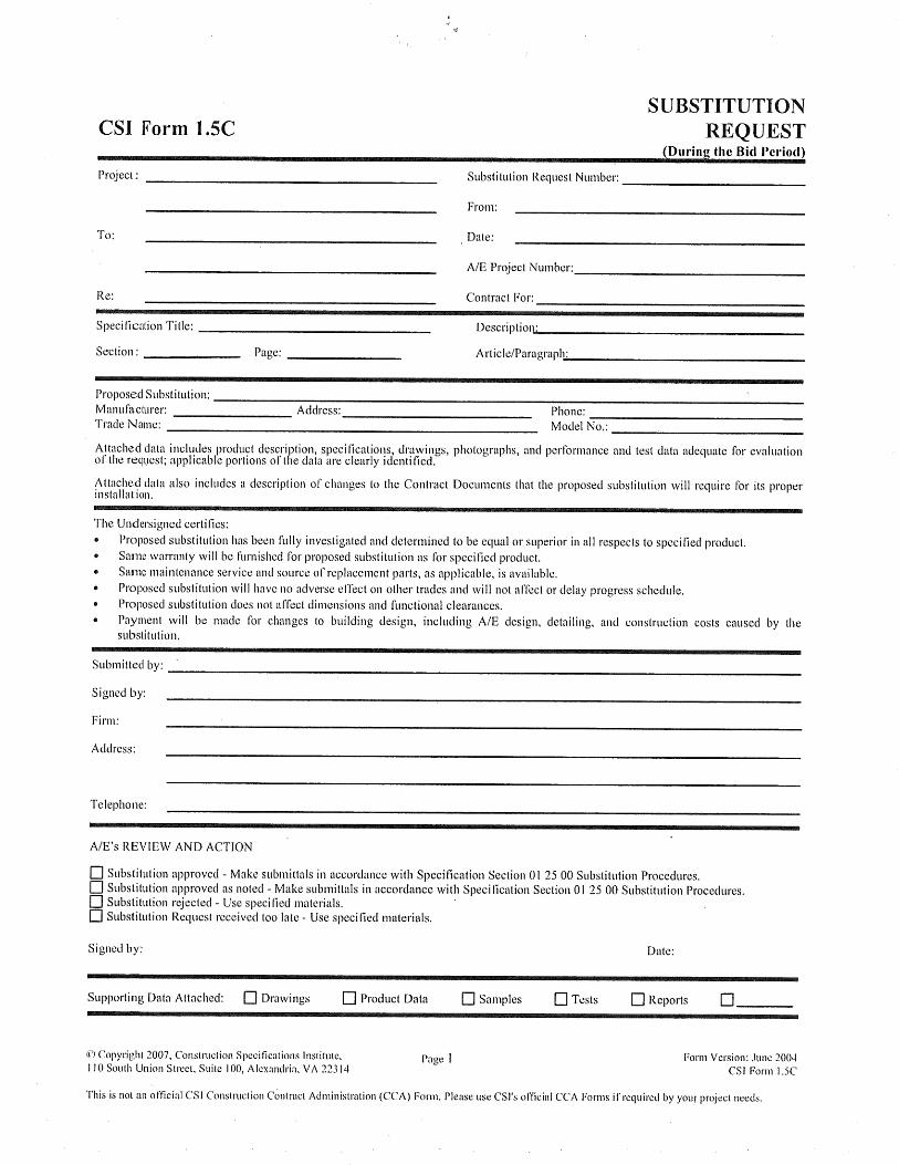
002600 PROCUREMENT SUBSTITUTION PROCEDURES 1 – 2
002605 SUBSTITUTION REQUEST (During the Bid Period) 1 – 2
005000 AIA DOCUMENTS 1 – 2
DIVISION 01 - GENERAL REQUIREMENTS
010000 GENERAL REQUIREMENTS 1 – 4
011000 SUMMARY 1 – 4
012500 SUBSTITUTION PROCEDURES 1 – 4
012501 SUBSTITUTION REQUEST (After the Bid Period) 1 – 2
012600 CONTRACT MODIFICATION PROCEDURES 1 – 4
012900 PAYMENT PROCEDURES 1 – 6
013100 PROJECT MANAGEMENT AND COORDINATION 1 – 8
013200 CONSTRUCTION PROGRESS DOCUMENTATION 1 – 8
013233 PHOTOGRAPHIC DOCUMENTATION 1 – 6
013300 SUBMITTAL PROCEDURES 1 – 12
SUBMITTAL TRANSMITTAL 1 – 2
013312 AJC ELECTRONIC FILES RELEASE FORM 1 – 2
014000 QUALITY REQUIREMENTS 1 – 10
015000 TEMPORARY FACILITIES AND CONTROLS 1 – 4
016000 PRODUCT REQUIREMENTS 1 – 6
017300 EXECUTION 1 – 10
017419 CONSTRUCTION WASTE MANAGEMENT AND DISPOSAL 1 – 2
017700 CLOSEOUT PROCEDURES 1 – 4
017823 OPERATION AND MAINTENANCE DATA 1 – 10
017839 PROJECT RECORD DOCUMENTS 1 – 4
DIVISION 02 - EXISTING CONDITIONS
024116 SELECTIVE DEMOLITION 1 – 4
DIVISION 03 - CONCRETE
(NOT USED)
DIVISION 04 - MASONRY
(NOT USED)
DIVISION 05 - METALS
055000 METAL FABRICATIONS 1 – 2
DIVISION 06 - WOOD AND PLASTICS
061053 MISCELLANEOUS ROUGH CARPENTRY 1 – 4

TABLE OF CONTENTS 2
064116 PLASTIC-LAMINATE-FACED ARCHITECTURAL CABINETS 1 – 8
DIVISION 07 - THERMAL AND MOISTURE PROTECTION
072100 ACOUSTIC INSULATION 1 – 4
079200 JOINT SEALANTS 1 – 14
DIVISION 08 - DOORS AND WINDOWS
081113 HOLLOW METAL DOORS AND FRAMES 1 – 10
081416 FLUSH WOOD DOORS 1 – 6
081433 STILE AND RAIL DOORS 1 – 6
083113 ACCESS DOORS AND FRAMES 1 – 4
083313 COILING COUNTER DOORS 1 – 8
084113 ALUMINUM-FRAMES ENTRANCES AND STOREFRONTS 1 – 8
087100 DOOR HARDWARE 1 – 14
088000 GLAZING 1 – 12
DIVISION 09 – FINISHES
092216 NON-STRUCTURAL METAL FRAMING 1 – 6
092900 GYPSUM BOARD 1 – 10
094113 ACOUSTIC PANEL CEILINGS 1 – 10
096513 RESILIENT BASE AND ACCESSORIES 1 – 6
096516 RESILIENT FLOORING – LINOLEUM FLOORING 1 – 8
096533 RESILIENT ESD VINYLE TILE FLOORING 1 – 8
096813 TILE CARPETING 1 – 4
099123 PAINTING 1 – 8
DIVISION 10 – SPECIALTIES
101100 VISUAL DISPLAY UNITS 1 – 10
101419 DIMENSIONAL LETTER SIGNAGE 1 – 6
101423 PANEL SIGNAGE 1 – 6
102600 WALL AND DOOR PROTECTION 1 – 6
104413 FIRE PROTECTION CABINETS 1 – 6
104416 FIRE EXTINGUISHERS 1 – 4
DIVISION 11 - EQUIPMENT
113100 RESIDENTIAL APPLIANCES 1 – 4
115213 PROJECTION SCREENS 1 – 4
DIVISION 12 - FURNISHINGS
122413 ROLLER WINDOW SHADES 1 – 6
123661 PLASTIC-LAMINATE-CLAD COUNTERTOPS 1 – 6
DIVISION 13 - SPECIAL CONSTRUCTION
(NOT USED)
DIVISION 14 - CONVEYING SYSTEMS
(NOT USED)
DIVISION 21- FIRE SUPPRESSION
211000 FIRE PROTECTION 1 – 10
DIVISION 22 – PLUMBING
221410 PLUMBING PIPING 1 – 8
221411 DISINFECTING WATER SUPPLY SYSTEM 1 – 6
221430 PLUMBING SPECIALITIES 1 – 12

TABLE OF CONTENTS 3
224440 PLUMBING FIXTURES 1 – 10
224450 PLUMBING EQUIPMENT 1 – 4
DIVISION 23 - HEATING, VENTILATIONING, AND AIR CONDITIONING
230080 SELECTIVE MECHANICAL DEMOLITION 1 – 4
230500 BASIC MECHANICAL REQUIREMENTS 1 – 8
230529 BASIC MECHQANICAL MATERIALS AND METHODS 1 – 32
230540 MECHANICAL SOUND AND VIBRATION CONTROL 1 – 20
230548 MECHANICAL SEISMIC CONTROL 1 – 6
230593 TESTING, ADJUSTING AND BALANCING 1 – 8
230700 MECHANICAL INSULATION 1 – 8
230900 ELECTRONIC CONTROLS 1 – 16
233300 DUCTWORK AND ACCESSORIES 1 – 14
233600 AIR TERMINAL UNITS 1 – 4
233713 AIR INLETS AND OUTLETS 1 – 4
DIVISION 25 - INTEGRATED AUTOMATION
(NONE USED)
DIVISION 26 – ELECTRICAL
260500 COMMON WORK RESULTS FOR ELECTRICAL 1 – 4
260519 LOW-VOLTAGE ELECTRICAL POWER CONDUCTORS AND CABLES 1 – 4
260526 GROUND AND BONDING FOR ELECTRICAL SYSTEMS 1 – 8
260529 HANGERS AND SUPPORTS FOR ELECTRICAL SYSTEMS 1 – 6
260533 RACEWAY AND BOXES FOR ELECTRICAL SYSTEMS 1 – 10
260536 CABLE TRAYS FOR ELECTRICAL SYSTEMS 1 – 8
260548 VIBRATION AND SEISMIC CONTROLS FOR ELECTRICAL SYSTEMS 1 – 8
260553 IDENTIFICATION FOR ELECTRICAL SYSTEMS 1 – 8
260923 DISTRIBUTED DIGITAL LIGHTING CONTROL SYSTSEMS 1 – 26
262726 WIRING DEVICES 1 – 8
262726.1 WIRING DEVICE SCHEDULE 1 – 2
265100 INTERIOR LIGHTING 1 – 10
DIVISION 27 – COMMUNICATIONS
(NONE USED)
DIVISION 28 - ELECTRONIC SAFETY AND SECURITY
283111 DIGITAL, ADDRESSABLE FIRE-ALARM SYSTEM 1 – 12
DIVISION 31 - EARTHWORK
(NONE USED)
DIVISION 32 - EXTERIOR IMPROVEMENTS
(NONE USED)
DIVISION 33 - UTILITIES
(NONE USED)

TABLE OF CONTENTS 4

SLCC WESTPOINTE – LEASE BLDG
2150 West Dauntless Avenue
Salt Lake City, Utah 84116
SEALS PAGE 000107 - 1
DOCUMENT 000107 - SEALS PAGE
1.1 DESIGN PROFESSIONALS OF RECORD
ARCHITECT ajc architects
703 East 1700 South
Salt Lake City, Utah 84105
1.801.466.8818
Contact: Steve Simmons
MECHANICAL
ENGINEER
COLVIN ENGINEERS
244 West 300 North Suite 200
Salt Lake City, Utah 84103
1.801.505.5404
Contact : Rob Van
ELECTRICAL
ENGINEER
SPECTRUM ENGINEERS
324 South State Street, Suite 400
Salt Lake City, Utah 84111
1.801.328.5151
Contact : Lance Kobayashi
END OF DOCUMENT 00010
Kobayashi
5497590-2202
Christopher KellyL
ICE
NS
ED
PROF ES S I ONA L
EN
GI N
EE
R
S T A T E O F U T A H
No.
11.16.2017

SLCC WESTPOINTE – LEASE BLDG
2150 West Dauntless Avenue
Salt Lake City, Utah 84116
SEALS PAGE 000107 - 2
THIS PAGE IS INTENTIONALLY LEFT BLANK

SLCC WESTPOINTE – LEASE BLDG 2150 West Dauntless Avenue
Salt Lake City, Utah 84116
PROCUREMENT SUBSTITUTION PROCEDURES 002600 - 1
DOCUMENT 002600 - PROCUREMENT SUBSTITUTION PROCEDURES
1.1 DEFINITIONS
A. Procurement Substitution Requests: Requests for changes in products, materials,
equipment, and methods of construction from those indicated in the Procurement and
Contracting Documents, submitted prior to receipt of bids.
B. Substitution Requests: Requests for changes in products, materials, equipment, and
methods of construction from those indicated in the Contract Documents, submitted
following Contract award. See Section 012500 "Substitution Procedures" for conditions
under which Substitution requests will be considered following Contract award.
1.2 QUALITY ASSURANCE
A. Compatibility of Substitutions: Investigate and document compatibility of proposed
substitution with related products and materials. Engage a qualified testing agency to
perform compatibility tests recommended by manufacturers.
1.3 PROCUREMENT SUBSTITUTIONS
A. Procurement Substitutions, General: By submitting a bid, the Bidder represents that its
bid is based on materials and equipment described in the Procurement and
Contracting Documents, including Addenda. Bidders are encouraged to request
approval of qualifying substitute materials and equipment when the Specifications
Sections list materials and equipment by product or manufacturer name.
B. Procurement Substitution Requests will be received and considered by Owner when the
following conditions are satisfied, as determined by Architect; otherwise requests will be
returned without action:
1. Extensive revisions to the Contract Documents are not required.
2. Proposed changes are in keeping with the general intent of the Contract
Documents, including the level of quality of the Work represented by the
requirements therein.
3. The request is fully documented and properly submitted.
1.4 SUBMITTALS
A. Procurement Substitution Request: Submit to Architect. Procurement Substitution
Request must be made in writing in compliance with the following requirements:
1. Requests for substitution of materials and equipment will be considered if
received no later than 10 days prior to date of bid opening.
2. Submittal Format: Submit three copies of each written Procurement Substitution
Request, using or CSI Substitution Request Form 1.5C, or one electronic submittal.

SLCC WESTPOINTE – LEASE BLDG 2150 West Dauntless Avenue
Salt Lake City, Utah 84116
PROCUREMENT SUBSTITUTION PROCEDURES 002600 - 2
a. Identify the product or the fabrication or installation method to be
replaced in each request. Include related Specifications Sections and
drawing numbers.
b. Provide complete documentation on both the product specified and the
proposed substitute, including the following information as appropriate:
1) Point-by-point comparison of specified and proposed substitute
product data, fabrication drawings, and installation procedures.
2) Copies of current, independent third-party test data of salient
product or system characteristics.
3) Samples where applicable or when requested by Architect.
4) Detailed comparison of significant qualities of the proposed substitute
with those of the Work specified. Significant qualities may include
attributes such as performance, weight, size, durability, visual effect,
sustainable design characteristics, warranties, and specific features
and requirements indicated. Indicate deviations, if any, from the
Work specified.
5) Material test reports from a qualified testing agency indicating and
interpreting test results for compliance with requirements indicated.
6) Research reports, where applicable, evidencing compliance with
building code in effect for Project, from ICC-ES.
7) Coordination information, including a list of changes or modifications
needed to other parts of the Work and to construction performed by
Owner and separate contractors, which will become necessary to
accommodate the proposed substitute.
c. Provide certification by manufacturer that the substitute proposed is equal
to or superior to that required by the Procurement and Contracting
Documents, and that its in-place performance will be equal to or superior
to the product or equipment specified in the application indicated.
d. Bidder, in submitting the Procurement Substitution Request, waives the right
to additional payment or an extension of Contract Time because of the
failure of the substitute to perform as represented in the Procurement
Substitution Request.
B. Architect's Action:
1. Architect may request additional information or documentation necessary for
evaluation of the Procurement Substitution Request. Architect will notify all
bidders of acceptance of the proposed substitute by means of an Addendum to
the Procurement and Contracting Documents.
C. Architect's approval of a substitute during bidding does not relieve Contractor of the
responsibility to submit required shop drawings and to comply with all other
requirements of the Contract Documents.
END OF DOCUMENT 002600

THIS PAGE IS INTENTIONALLY LEFT BLANK

SLCC WESTPOINTE – LEASE BLDG 2150 West Dauntless Avenue Salt Lake City, Utah 84116
AIA FORMS 005000-1
SECTION 005000 – AIA DOCUMENT FORMS
1. AIA Documents, but not limited to, or Software-generated forms with substantially the same content that may be used on this project.
AIA Document G701 - 2001, Change Order.
AIA Document G702 – 1992, Application and Certificate for Payment.
AIA Document G703 – 1992, Continuation Sheet, Application and Certificate for Payment.
AIA Document G704 – 2000, Certificate of Substantial Completion.
AIA Document G706A – 1994, Contractor’s Affidavit of Release of Liens.
AIA Document G707 – 1994, Consent of Surety to Final Payment.
AIA Document G710 – 1992, Architect’s Supplemental Instructions.
AIA Document G714 – 2007, Construction Change Directive.
END OF DOCUMENT

SLCC WESTPOINTE – LEASE BLDG 2150 West Dauntless Avenue Salt Lake City, Utah 84116
AIA FORMS 005000-2
THIS PAGE IS INTENTIONALLY LEFT BLANK

SLCC WESTPOINTE – LEASE BLDG 2150 West Dauntless Avenue
Salt Lake City, Utah 84116
GENERAL REQUIREMENTS 010010 - 1
SECTION 010010 – GENERAL REQUIREMENTS
PART 1 - GENERAL
1.1 RELATED DOCUMENTS
A. Drawings and general provisions of the Contract, including General and
Supplementary Conditions and Division 01 Specification Sections, apply to this Section.
1.2 SUMMARY
A. This Section includes general requirements that are to apply to all Work throughout the
Project. Requirements included in this Section are to apply to all other specification
Sections.
1.3 DEFINITIONS
A. General: Basic Contract definitions are included in the Conditions of the Contract.
B. "Approved": When used to convey Architect's action on Contractor's submittals,
applications, and requests, "approved" is limited to Architect's duties and responsibilities
as stated in the Conditions of the Contract.
C. “Center of...”: Indicates a specific single point at the exact center of the tile, panel, or
other surface indicated.
D. “Contractor”: The General Contractor unless otherwise stated.
E. "Directed": A command or instruction by Architect, unless indicated as by Owner.
Other terms including "requested," "authorized," "selected," "approved," "required," and
"permitted" have the same meaning as "directed."
F. "Furnish": Supply and deliver to Project site, ready for unloading, unpacking, assembly,
installation, and similar operations.
G. "Indicated": Requirements expressed by graphic representations or in written form on
Drawings, in Specifications, and in other Contract Documents. Other terms including
"shown," "noted," "scheduled," and "specified" have the same meaning as "indicated."
H. "Install": Operations at Project site including unloading, temporarily storing, unpacking,
assembling, erecting, placing, anchoring, applying, working to dimension, finishing,
curing, protecting, cleaning, and similar operations.
I. “Project Manager”: The Contractor’s project manager.
J. “Project Representative”: The Owner’s project representative(s).

SLCC WESTPOINTE – LEASE BLDG 2150 West Dauntless Avenue
Salt Lake City, Utah 84116
GENERAL REQUIREMENTS 010010 - 2
K. "Project Site": Space available for performing construction activities. The extent of
Project site is shown on Drawings and may or may not be identical with the description
of the land on which Project is to be built.
L. "Provide": Furnish and install, complete and ready for the intended use.
M. "Regulations": Laws, ordinances, statutes, and lawful orders issued by authorities having
jurisdiction, and rules, conventions, and agreements within the construction industry
that control performance of the Work.
N. “Related Sections”: Related Sections articles are included herein as a courtesy to assist
in the locating of items in the specifications that the reader might expect to find in the
Section but that are specified elsewhere. The list of sections may or may not be
complete. ‘Related Sections’ articles do not relieve the Contractor of the contractual
obligation to perform to all the Contract Documents or to coordinate who does what
amongst the team of subcontractors.
O. “Project Site”: Location may be at the actual location where construction is taking
place or may represent the SLCDA’s Engineering Conference Room or other locations
as determined by the owner.
1.4 SITE INSPECTION
A. Examine the premises and site and compare them with the drawings and
specifications.
B. Become familiar with existing conditions such as obstructive areas, excavating or filling,
and any problems related to construction. No allowances will subsequently be made
by reason of failure to examine the site.
C. The General Contractor is responsible for being aware of all required special
inspections and for scheduling inspections with the owner.
1.5 SCOPE OF THE WORK
A. See Division 01 Section 011000 “Summary” for an overall general summary of the Work.
B. Unless otherwise provided, all materials, labor, equipment, tools, transportation, and
utilities necessary for the successful completion of the Project shall be provided at the
expense of the Contractor.
C. Requirements of the Work are contained in the Contract Documents, and include
cross-references herein to published information, which is not necessarily bound
therewith.
D. Provide and Install all Work so that its several component parts function together as a
complete and workable system, and with all equipment properly adjusted and in
working order.

SLCC WESTPOINTE – LEASE BLDG 2150 West Dauntless Avenue
Salt Lake City, Utah 84116
GENERAL REQUIREMENTS 010010 - 3
E. Conform to highest quality standards for materials and workmanship to execute Work
that is indicated or specified and that is necessary to fully satisfy the Contract
Document requirements for a complete, finished, acceptable installation regardless of
whether indicated or specified or not.
F. Responsibilities of the Contractor includes the responsibility to verify all field
measurements of actual building conditions so that all Work fits properly in the locations
indicated and specified. Protect existing structures, improvements, trees, and other
items from physical damage, unless identified to be removed.
G. Contractor is to restore roads, utilities, walks, curbs, gutters or other improvements
belonging to the Owner, to the same condition as they existed prior to
commencement of construction. Where said improvements are damaged, they shall
be replaced by new Work to match existing adjacent Work, or repaired if acceptable
to Project Representative, at no cost to Owner.
H. Where there are conflicts that may exist between the contract documents the most
stringent requirements shall govern.
1.6 WORKERS
A. The Contractor is to enforce strict discipline and good order among his/her employees
at all times and shall not employ on the Project any unfit person or anyone not skilled in
the Work assigned to him/her.
B. Consumption of alcohol, tobacco, or any other controlled, non-medically prescribed
substance will not be allowed on the Project.
C. Contractor shall rectify behavior unacceptable to the Owner or Owner’s Project
Representative by strict enforcement of discipline. Owner reserves the right to request
dismissal of individual workers for failure to comply with standards of behavior
communicated to the Contractor.
1.7 TAXES
A. The Contractor shall pay sales, use, payroll, unemployment, old age pension, or surtax
applicable to this project.
B. The Owner shall pay taxes and assessments on real property comprising the site of this
project.
1.8 MANUFACTURER’S DIRECTIONS
A. Manufactured articles, materials, or equipment shall be applied, installed, connected,
erected, used, cleaned, and conditioned in accordance with the Manufacturer’s
printed directions unless otherwise indicated in the Contract Documents.

SLCC WESTPOINTE – LEASE BLDG 2150 West Dauntless Avenue
Salt Lake City, Utah 84116
GENERAL REQUIREMENTS 010010 - 4
1.9 FASTENERS
A. Unless noted otherwise, the trade requiring the fastening of its Work to any substrate or
support is responsible for provision and installation of requisite fasteners.
1.10 PENETRATIONS
A. The sealing of all penetrations in fire-rated, acoustically-rated or structural partitions and
separations is the responsibility of the trade making or requiring the penetration.
PART 2 - PRODUCTS (Not Used)
PART 3 - EXECUTION (Not Used)
END OF SECTION 011010

SLCC WESTPOINTE – LEASE BLDG 2150 West Dauntless Avenue
Salt Lake City, Utah 84116
SUMMARY 011000 - 1
SECTION 011000 - SUMMARY
PART 1 - GENERAL
1.1 RELATED DOCUMENTS
1.2 Drawings and general provisions of the Contract, including General and
Supplementary Conditions and Division 01 Specification Sections, apply to this Section.
1.3 SUMMARY
A. Section Includes:
1. Project information.
2. Work covered by Contract Documents.
3. Access to site.
4. Work restrictions.
5. Specification and drawing conventions.
1.4 PROJECT INFORMATION
A. There are two projects that this specification is part of:
B. Project Identification: SLCC WESTPOINTE – LEASE BLDG
2150 West Dauntless Ave.
Salt Lake City, Utah 84116
Owner: SALT LAKE COMMUNITY COLLEGE
4600 South Redwood Road
Salt Lake City, Utah 84123
1. Owner's Representative: Malin Francis, 1.801.957.5177
C. Architect: ajc architects; Heber Slabbert; 1.801.466.8818
D. Architect's Consultants: The Architect has retained the following design professionals
who have prepared designated portions of the Contract Documents:
1. MECHANICAL ENGINEERING Colvin Engineers
244 West 300 North Suite 200
Salt Lake City, Utah 84103
1.801.505.5404
Contact : Rob Van;

SLCC WESTPOINTE – LEASE BLDG 2150 West Dauntless Avenue
Salt Lake City, Utah 84116
SUMMARY 011000 - 2
2. ELECTRICAL ENGINEERING Spectrum Engineers
324 South State Treet Suite 400
Salt Lake City, Utah 84111
1.8015.3289.5151
Contact : Lance Kobayashi
WORK COVERED BY CONTRACT DOCUMENTS
The Work of Project is defined by the Contract Documents and consists of the following:
The SLCC Westpointe Lease Building project, includes the demolition and remodel of
existing areas of an occupied educational facility. These spaces include lab spaces,
classrooms, conference rooms and offices. The intent of the remodel is to provide the
needed student services to support the new Westpointe Technology Facility under con-
struction on the same street. The finished remodel is intended to adhere to/match the
finishes of the existing facility to provide a consistent appearance throughout the build-
ing.
The remodel also includes electrical, communications, lighting and mechanical sys-
tems, with no intended structural modifications to the facility. With the exception of mi-
nor exterior lighting improvements, there will be no work performed on the exterior of
the facility. The spaces intended to meet Salt Lake Community College construction
and design standards.
E. Type of Contract:
1. Project will be constructed under a single prime contract.
1.5 ACCESS TO SITE
A. General: Contractor shall have limited use of Project site for construction operations
during construction period. Contractor's use of Project site is limited by Owner's right to
perform work or to retain other contractors on portions of Project.
B. Use of Site: Limit use of Project site to areas within the Contract limits indicated.
1.6 WORK RESTRICTIONS
A. Work Restrictions, General: Comply with restrictions on construction operations.
1. Comply with limitations on use of public streets and with other requirements of
authorities having jurisdiction.
B. On-Site Work Hours:
1. Comply with requirements of authorities of Jurisdiction.

SLCC WESTPOINTE – LEASE BLDG 2150 West Dauntless Avenue
Salt Lake City, Utah 84116
SUMMARY 011000 - 3
C. Noise, Vibration, and Odors: Coordinate operations that may result in high levels of
noise and vibration, odors, or other disruption.
D. Controlled Substances: Use of tobacco products and other controlled substances on
Project site is not permitted.
1.7 SPECIFICATION AND DRAWING CONVENTIONS
A. Specification Content: The Specifications use certain conventions for the style of
language and the intended meaning of certain terms, words, and phrases when used
in particular situations. These conventions are as follows:
1. Imperative mood and streamlined language are generally used in the
Specifications. The words "shall," "shall be," or "shall comply with," depending on
the context, are implied where a colon (:) is used within a sentence or phrase.
2. Specification requirements are to be performed by Contractor unless specifically
stated otherwise.
B. Division 01 General Requirements: Requirements of Sections in Division 01 apply to the
Work of all Sections in the Specifications.
C. Drawing Coordination: Requirements for materials and products identified on Drawings
are described in detail in the Specifications. One or more of the following are used on
Drawings to identify materials and products:
1. Terminology: Materials and products are identified by the typical generic terms
used in the individual Specifications Sections.
2. Abbreviations: Materials and products may be identified by abbreviations
published as part of the U.S. National CAD Standard and scheduled on Drawings.
3. Keynoting: Materials and products are identified by reference keynotes
referencing Specification Section numbers found in this Project Manual.
PART 2 - PRODUCTS (Not Used)
PART 3 - EXECUTION (Not Used)
END OF SECTION 011000

SLCC WESTPOINTE – LEASE BLDG 2150 West Dauntless Avenue
Salt Lake City, Utah 84116
SUMMARY 011000 - 4
THIS PAGE IS INTENTIONALLY LEFT BLANK

SLCC WESTPOINTE – LEASE BLDG 2150 West Dauntless Avenue
Salt Lake City, Utah 84116
SUBSTITUTION PROCEDURES 012500 - 1
SECTION 012500 - SUBSTITUTION PROCEDURES
PART 1 - GENERAL
1.1 RELATED DOCUMENTS
A. Drawings and general provisions of the Contract, including General and
Supplementary Conditions and Division 01 Specification Sections, apply to this Section.
1.2 SUMMARY
A. Section includes administrative and procedural requirements for substitutions.
B. Related Requirements:
1. Section 016000 "Product Requirements" for requirements for submitting
comparable product submittals for products by listed manufacturers.
1.3 DEFINITIONS
A. Substitutions: Changes in products, materials, equipment, and methods of construction
from those required by the Contract Documents and proposed by Contractor.
1. Substitutions for Cause: Changes proposed by Contractor that are required due
to changed Project conditions, such as unavailability of product, regulatory
changes, or unavailability of required warranty terms.
2. Substitutions for Convenience: Changes proposed by Contractor or Owner that
are not required in order to meet other Project requirements but may offer
advantage to Contractor or Owner.
1.4 ACTION SUBMITTALS
A. Substitution Requests: Submit three copies of each request for consideration. Identify
product or fabrication or installation method to be replaced. Include Specification
Section number and title and Drawing numbers and titles.
1. Substitution Request Form: Use CSI Form 13.1A.
2. Documentation: Show compliance with requirements for substitutions and the
following, as applicable:
a. Statement indicating why specified product or fabrication or installation
cannot be provided, if applicable.
b. Coordination information, including a list of changes or revisions needed to
other parts of the Work and to construction performed by Owner and
separate contractors, that will be necessary to accommodate proposed
substitution.

SLCC WESTPOINTE – LEASE BLDG 2150 West Dauntless Avenue
Salt Lake City, Utah 84116
SUBSTITUTION PROCEDURES 012500 - 2
c. Detailed comparison of significant qualities of proposed substitution with
those of the Work specified. Include annotated copy of applicable
Specification Section. Significant qualities may include attributes such as
performance, weight, size, durability, visual effect, sustainable design
characteristics, warranties, and specific features and requirements
indicated. Indicate deviations, if any, from the Work specified.
d. Product Data, including drawings and descriptions of products and
fabrication and installation procedures.
e. Samples, where applicable or requested.
f. Certificates and qualification data, where applicable or requested.
g. List of similar installations for completed projects with project names and
addresses and names and addresses of architects and owners.
h. Material test reports from a qualified testing agency indicating and
interpreting test results for compliance with requirements indicated.
i. Research reports evidencing compliance with building code in effect for
Project, from ICC-ES.
j. Detailed comparison of Contractor's construction schedule using proposed
substitution with products specified for the Work, including effect on the
overall Contract Time. If specified product or method of construction
cannot be provided within the Contract Time, include letter from
manufacturer, on manufacturer's letterhead, stating date of receipt of
purchase order, lack of availability, or delays in delivery.
k. Cost information, including a proposal of change, if any, in the Contract
Sum.
l. Contractor's certification that proposed substitution complies with
requirements in the Contract Documents except as indicated in substitution
request, is compatible with related materials, and is appropriate for
applications indicated.
m. Contractor's waiver of rights to additional payment or time that may
subsequently become necessary because of failure of proposed
substitution to produce indicated results.
3. Architect's Action: If necessary, Architect will request additional information or
documentation for evaluation within 5 days of receipt of a request for
substitution. Architect will notify Contractor of acceptance or rejection of
proposed substitution within 15 days of receipt of request, or 7 days of receipt of
additional information or documentation, whichever is later.
a. Forms of Acceptance: Change Order, Construction Change Directive, or
Architect's Supplemental Instructions for minor changes in the Work.
b. Use product specified if Architect does not issue a decision on use of a
proposed substitution within time allocated.
1.5 QUALITY ASSURANCE
A. Compatibility of Substitutions: Investigate and document compatibility of proposed
substitution with related products and materials. Engage a qualified testing agency to
perform compatibility tests recommended by manufacturers.

SLCC WESTPOINTE – LEASE BLDG 2150 West Dauntless Avenue
Salt Lake City, Utah 84116
SUBSTITUTION PROCEDURES 012500 - 3
1.6 PROCEDURES
A. Coordination: Revise or adjust affected work as necessary to integrate work of the
approved substitutions.
PART 2 - PRODUCTS
2.1 SUBSTITUTIONS
A. Substitutions for Cause: Submit requests for substitution immediately on discovery of
need for change, but not later than 15 days prior to time required for preparation and
review of related submittals.
1. Conditions: Architect will consider Contractor's request for substitution when the
following conditions are satisfied. If the following conditions are not satisfied,
Architect will return requests without action, except to record noncompliance
with these requirements:
a. Requested substitution is consistent with the Contract Documents and will
produce indicated results.
b. Substitution request is fully documented and properly submitted.
c. Requested substitution will not adversely affect Contractor's construction
schedule.
d. Requested substitution has received necessary approvals of authorities
having jurisdiction.
e. Requested substitution is compatible with other portions of the Work.
f. Requested substitution has been coordinated with other portions of the
Work.
g. Requested substitution provides specified warranty.
h. If requested substitution involves more than one contractor, requested
substitution has been coordinated with other portions of the Work, is uniform
and consistent, is compatible with other products, and is acceptable to all
contractors involved.
B. Substitutions for Convenience: Architect will consider requests for substitution if
received within 30 days after the Notice to Proceed. Requests received after that time
may be considered or rejected at discretion of Architect.
1. Conditions: Architect will consider Contractor's request for substitution when the
following conditions are satisfied. If the following conditions are not satisfied,
Architect will return requests without action, except to record noncompliance
with these requirements:
a. Requested substitution offers Owner a substantial advantage in cost, time,
energy conservation, or other considerations, after deducting additional
responsibilities Owner must assume. Owner's additional responsibilities may
include compensation to Architect for redesign and evaluation services,
increased cost of other construction by Owner, and similar considerations.

SLCC WESTPOINTE – LEASE BLDG 2150 West Dauntless Avenue
Salt Lake City, Utah 84116
SUBSTITUTION PROCEDURES 012500 - 4
b. Requested substitution does not require extensive revisions to the Contract
Documents.
c. Requested substitution is consistent with the Contract Documents and will
produce indicated results.
d. Substitution request is fully documented and properly submitted.
e. Requested substitution will not adversely affect Contractor's construction
schedule.
f. Requested substitution has received necessary approvals of authorities
having jurisdiction.
g. Requested substitution is compatible with other portions of the Work.
h. Requested substitution has been coordinated with other portions of the
Work.
i. Requested substitution provides specified warranty.
j. If requested substitution involves more than one contractor, requested
substitution has been coordinated with other portions of the Work, is uniform
and consistent, is compatible with other products, and is acceptable to all
contractors involved.
PART 3 - EXECUTION (Not Used)
END OF SECTION 012500
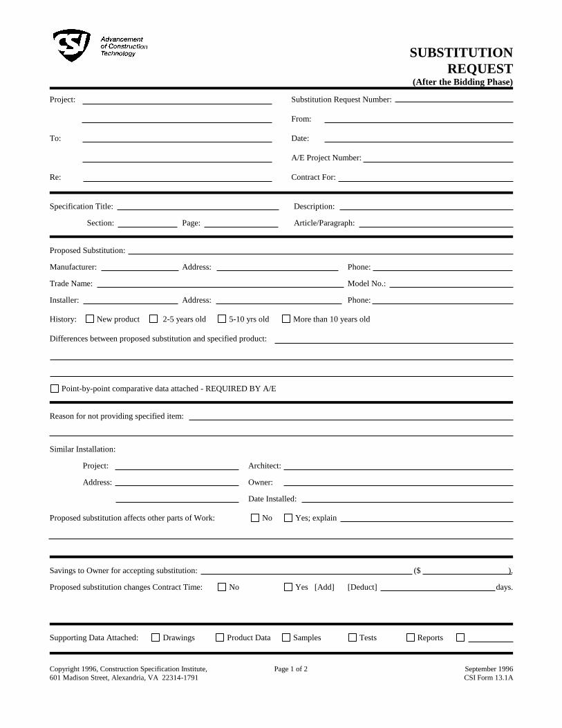
SUBSTITUTION
REQUEST
(After the Bidding Phase) Project:
To:
Re:
Substitution Request Number:
From:
Date:
A/E Project Number:
Contract For:
Specification Title: Description:
Section: Page: Article/Paragraph: Proposed Substitution: Manufacturer: Address: Phone: Trade Name: Model No.: Installer: Address: Phone:
History: New product 2-5 years old 5-10 yrs old More than 10 years old
Differences between proposed substitution and specified product:
Point-by-point comparative data attached - REQUIRED BY A/E Reason for not providing specified item: Similar Installation:
Project: Architect:
Address: Owner:
Date Installed:
Proposed substitution affects other parts of Work: No Yes; explain Savings to Owner for accepting substitution: ($ ). Proposed substitution changes Contract Time: No Yes [Add] [Deduct] days.
Supporting Data Attached: Drawings Product Data Samples Tests Reports
Copyright 1996, Construction Specification Institute,
601 Madison Street, Alexandria, VA 22314-1791 Page 1 of 2 September 1996
CSI Form 13.1A

SUBSTITUTION
REQUEST (Continued)
The Undersigned certifies:
• Proposed substitution has been fully investigated and determined to be equal or superior in all respects to specified product.
• Same warranty will be furnished for proposed substitution as for specified product.
• Same maintenance service and source of replacement parts, as applicable, is available.
• Proposed substitution will have no adverse effect on other trades and will not affect or delay progress schedule.
• Cost data as stated above is complete. Claims for additional costs related to accepted substitution which may subsequently become
apparent are to be waived.
• Proposed substitution does not affect dimensions and functional clearances.
• Payment will be made for changes to building design, including A/E design, detailing, and construction costs caused by the
substitution.
• Coordination, installation, and changes in the Work as necessary for accepted substitution will be complete in all respects. Submitted by: Signed by: Firm: Address:
Telephone: Attachments:
A/E's REVIEW AND ACTION
Substitution approved - Make submittals in accordance with Specification Section 01330.
Substitution approved as noted - Make submittals in accordance with Specification Section 01330.
Substitution rejected - Use specified materials.
Substitution Request received too late - Use specified materials.
Signed by: Date: Additional Comments: Contractor Subcontractor Supplier Manufacturer A/E
Copyright 1996, Construction Specification Institute,
601 Madison Street, Alexandria, VA 22314-1791 Page 22 of 2 September 1996
CSI Form 13.1A

SLCC WESTPOINTE – LEASE BLDG 2150 West Dauntless Avenue
Salt Lake City, Utah 84116
CONTRACT MODIFICATION PROCEDURES 012600 - 1
SECTION 012600 - CONTRACT MODIFICATION PROCEDURES
PART 1 - GENERAL
1.1 RELATED DOCUMENTS
A. Drawings and general provisions of the Contract, including General and
Supplementary Conditions and Division 01 Specification Sections, apply to this Section.
1.2 SUMMARY
A. Section includes administrative and procedural requirements for handling and
processing Contract modifications.
B. Related Requirements:
1. Section 012500 "Substitution Procedures" for administrative procedures for
handling requests for substitutions made after the Contract award.
1.3 MINOR CHANGES IN THE WORK
A. Owner will issue supplemental instructions authorizing minor changes in the Work, not
involving adjustment to the Contract Sum or the Contract Time, on ajc architects’
standard, "Architect's Supplemental Instructions." The Architect with assistance of the
owner will direct changes.
1.4 PROPOSAL REQUESTS
A. Owner-Initiated Proposal Requests: The Owner will issue a description of proposed
changes in the Work that may require adjustment to the Contract Sum or the Contract
Time. If necessary, the description will include supplemental or revised Drawings and
Specifications. The Architect with assistance of the owner will direct changes.
1. Work Change Proposal Requests issued by Architect with the assistance of the
owner are not instructions either to stop work in progress or to execute the
proposed change.
2. Within time specified in Proposal Request or 10 days, when not otherwise
specified, after receipt of Proposal Request, submit a quotation estimating cost
adjustments to the Contract Sum and the Contract Time necessary to execute
the change.
a. Include a list of quantities of products required or eliminated and unit costs,
with total amount of purchases and credits to be made. If requested,
furnish survey data to substantiate quantities.
b. Indicate applicable taxes, delivery charges, equipment rental, and
amounts of trade discounts.
c. Include costs of labor and supervision directly attributable to the change.

SLCC WESTPOINTE – LEASE BLDG 2150 West Dauntless Avenue
Salt Lake City, Utah 84116
CONTRACT MODIFICATION PROCEDURES 012600 - 2
d. Include an updated Contractor's construction schedule that indicates the
effect of the change, including, but not limited to, changes in activity
duration, start and finish times, and activity relationship. Use available total
float before requesting an extension of the Contract Time.
e. Quotation Form: Use form that is acceptable to the Architect and Owner.
B. Contractor-Initiated Proposals: If latent or changed conditions require modifications to
the Contract, Contractor may initiate a claim by submitting a request for a change to
the Owner.
1. Include a statement outlining reasons for the change and the effect of the
change on the Work. Provide a complete description of the proposed change.
Indicate the effect of the proposed change on the Contract Sum and the
Contract Time.
2. Include a list of quantities of products required or eliminated and unit costs, with
total amount of purchases and credits to be made. If requested, furnish survey
data to substantiate quantities.
3. Indicate applicable taxes, delivery charges, equipment rental, and amounts of
trade discounts.
4. Include costs of labor and supervision directly attributable to the change.
5. Include an updated Contractor's construction schedule that indicates the effect
of the change, including, but not limited to, changes in activity duration, start
and finish times, and activity relationship. Use available total float before
requesting an extension of the Contract Time.
6. Comply with requirements in Section 012500 "Substitution Procedures" if the
proposed change requires substitution of one product or system for product or
system specified.
7. Proposal Request Form: Use form acceptable to Architect and Owner.
1.5 CHANGE ORDER PROCEDURES
A. On Owner's approval of a Work Changes Proposal Request, Architect or Owner will
issue a Change Order for signatures of Owner and Contractor on AIA Document G701.
1.6 CONSTRUCTION CHANGE DIRECTIVE
A. Construction Change Directive: Owner may issue a Construction Change Directive on
AIA Document G714. Construction Change Directive instructs Contractor to proceed
with a change in the Work, for subsequent inclusion in a Change Order.
1. Construction Change Directive contains a complete description of change in the
Work. It also designates method to be followed to determine change in the
Contract Sum or the Contract Time.
B. Documentation: Maintain detailed records on a time and material basis of work
required by the Construction Change Directive.
1. After completion of change, submit an itemized account and supporting data
necessary to substantiate cost and time adjustments to the Contract.

SLCC WESTPOINTE – LEASE BLDG 2150 West Dauntless Avenue
Salt Lake City, Utah 84116
CONTRACT MODIFICATION PROCEDURES 012600 - 3
PART 2 - PRODUCTS (Not Used)
PART 3 - EXECUTION (Not Used)
END OF SECTION 012600

SLCC WESTPOINTE – LEASE BLDG 2150 West Dauntless Avenue
Salt Lake City, Utah 84116
CONTRACT MODIFICATION PROCEDURES 012600 - 4
THIS PAGE IS INTENTIONALLY LEFT BLANK

SLCC WESTPOINTE – LEASE BLDG 2150 West Dauntless Avenue
Salt Lake City, Utah 84116
PAYMENT PROCEDURES 012900 - 1
SECTION 012900 - PAYMENT PROCEDURES
PART 1 - GENERAL
1.1 RELATED DOCUMENTS
A. Drawings and general provisions of the Contract, including General and
Supplementary Conditions and other Division 01 Specification Sections, apply to this
Section.
1.2 SUMMARY
A. Section includes administrative and procedural requirements necessary to prepare and
process Applications for Payment.
B. Related Requirements:
1. Section 012600 "Contract Modification Procedures" for administrative procedures
for handling changes to the Contract.
2. Section 013200 "Construction Progress Documentation" for administrative
requirements governing the preparation and submittal of the Contractor's
construction schedule.
1.3 DEFINITIONS
A. Schedule of Values: A statement furnished by Contractor allocating portions of the
Contract Sum to various portions of the Work and used as the basis for reviewing
Contractor's Applications for Payment.
1.4 SCHEDULE OF VALUES
A. Coordination: Coordinate preparation of the schedule of values with preparation of
Contractor's construction schedule. Cost-loaded Critical Path Method Schedule may
serve to satisfy requirements for the schedule of values when acceptable to Owner.
1. Coordinate line items in the schedule of values with other required administrative
forms and schedules, including the following:
a. Application for Payment forms with continuation sheets.
b. Submittal schedule.
c. Items required to be indicated as separate activities in Contractor's
construction schedule.
2. Submit the schedule of values to Architect at earliest possible date, but no later
than seven days before the date scheduled for submittal of initial Applications for
Payment.

SLCC WESTPOINTE – LEASE BLDG 2150 West Dauntless Avenue
Salt Lake City, Utah 84116
PAYMENT PROCEDURES 012900 - 2
B. Format and Content: Use Project Manual table of contents as a guide to establish line
items for the schedule of values. Provide at least one line item for each Specification
Section.
1. Identification: Include the following Project identification on the schedule of
values:
a. Project name and location.
b. Name of Architect.
c. Architect's project number.
d. Contractor's name and address.
e. Date of submittal.
2. Arrange schedule of values consistent with format of AIA Document G703 or form
acceptable to Owner and Architect.
3. Arrange the schedule of values in tabular form with separate columns to indicate
the following for each item listed:
a. Related Specification Section or Division.
b. Description of the Work.
c. Name of subcontractor.
d. Name of manufacturer or fabricator.
e. Name of supplier.
f. Change Orders (numbers) that affect value.
g. Dollar value of the following, as a percentage of the Contract Sum to
nearest one-hundredth percent, adjusted to total 100 percent.
1) Labor.
2) Materials.
3) Equipment.
4. Provide a breakdown of the Contract Sum in enough detail to facilitate
continued evaluation of Applications for Payment and progress reports.
Coordinate with Project Manual table of contents.
a. Include separate line items under principal subcontracts for Project
closeout requirements in an amount totaling five percent of the Contract
Sum and subcontract amount.
5. Round amounts to nearest whole dollar; total shall equal the Contract Sum.
6. Provide a separate line item in the schedule of values for each part of the Work
where Applications for Payment may include materials or equipment purchased
or fabricated and stored, but not yet installed.
a. Differentiate between items stored on-site and items stored off-site. If
required, include evidence of insurance.
7. Provide separate line items in the schedule of values for initial cost of materials, for
each subsequent stage of completion, and for total installed value of that part of
the Work.

SLCC WESTPOINTE – LEASE BLDG 2150 West Dauntless Avenue
Salt Lake City, Utah 84116
PAYMENT PROCEDURES 012900 - 3
8. Each item in the schedule of values and Applications for Payment shall be
complete. Include total cost and proportionate share of general overhead and
profit for each item.
a. Temporary facilities and other major cost items that are not direct cost of
actual work-in-place may be shown either as separate line items in the
schedule of values or distributed as general overhead expense, at
Contractor's option.
9. Schedule Updating: Update and resubmit the schedule of values before the next
Applications for Payment when Change Orders or Construction Change
Directives result in a change in the Contract Sum.
1.5 APPLICATIONS FOR PAYMENT
A. Each Application for Payment following the initial Application for Payment shall be
consistent with previous applications and payments as certified by Architect and paid
for by Owner.
1. Initial Application for Payment, Application for Payment at time of Substantial
Completion, and final Application for Payment involve additional requirements.
B. Payment Application Times: The date for each progress payment is indicated in the
Agreement between Owner and Contractor. The period of construction work covered
by each Application for Payment is the period indicated in the Agreement.
C. Application for Payment Forms: Use AIA Document G702 and AIA Document G703 as
form for Applications for Payment.
D. Application Preparation: Complete every entry on form. Notarize and execute by a
person authorized to sign legal documents on behalf of Contractor. Architect will
return incomplete applications without action.
1. Entries shall match data on the schedule of values and Contractor's construction
schedule. Use updated schedules if revisions were made.
2. Include amounts for work completed following previous Application for Payment,
whether or not payment has been received. Include only amounts for work
completed at time of Application for Payment.
3. Include amounts of Change Orders and Construction Change Directives issued
before last day of construction period covered by application.
4. Indicate separate amounts for work being carried out under Owner-requested
project acceleration.
E. Stored Materials: Include in Application for Payment amounts applied for materials or
equipment purchased or fabricated and stored, but not yet installed. Differentiate
between items stored on-site and items stored off-site.
1. Provide certificate of insurance, evidence of transfer of title to Owner, and
consent of surety to payment, for stored materials.

SLCC WESTPOINTE – LEASE BLDG 2150 West Dauntless Avenue
Salt Lake City, Utah 84116
PAYMENT PROCEDURES 012900 - 4
2. Provide supporting documentation that verifies amount requested, such as paid
invoices. Match amount requested with amounts indicated on documentation;
do not include overhead and profit on stored materials.
3. Provide summary documentation for stored materials indicating the following:
a. Value of materials previously stored and remaining stored as of date of
previous Applications for Payment.
b. Value of previously stored materials put in place after date of previous
Application for Payment and on or before date of current Application for
Payment.
c. Value of materials stored since date of previous Application for Payment
and remaining stored as of date of current Application for Payment.
F. Transmittal: Submit three signed and notarized original copies of each Application for
Payment to Architect by a method ensuring receipt within 24 hours. One copy shall
include waivers of lien and similar attachments if required.
1. Transmit each copy with a transmittal form listing attachments and recording
appropriate information about application.
G. Waivers of Mechanic's Lien: With each Application for Payment, submit waivers of
mechanic's liens from subcontractors, sub-subcontractors, and suppliers for construction
period covered by the previous application.
1. Submit partial waivers on each item for amount requested in previous
application, after deduction for retainage, on each item.
2. When an application shows completion of an item, submit conditional final or full
waivers.
3. Owner reserves the right to designate which entities involved in the Work must
submit waivers.
4. Submit final Application for Payment with or preceded by conditional final
waivers from every entity involved with performance of the Work covered by the
application who is lawfully entitled to a lien.
5. Waiver Forms: Submit executed waivers of lien on forms, acceptable to Owner.
H. Initial Application for Payment: Administrative actions and submittals that must
precede or coincide with submittal of first Application for Payment include the
following:
1. List of subcontractors.
2. Schedule of values.
3. Contractor's construction schedule (preliminary if not final).
4. Combined Contractor's construction schedule (preliminary if not final)
incorporating Work of multiple contracts, with indication of acceptance of
schedule by each Contractor.
5. Products list (preliminary if not final).
6. Submittal schedule (preliminary if not final).
7. List of Contractor's staff assignments.
8. List of Contractor's principal consultants.
9. Copies of building permits.

SLCC WESTPOINTE – LEASE BLDG 2150 West Dauntless Avenue
Salt Lake City, Utah 84116
PAYMENT PROCEDURES 012900 - 5
10. Copies of authorizations and licenses from authorities having jurisdiction for
performance of the Work.
11. Initial progress report.
12. Report of preconstruction conference.
13. Certificates of insurance and insurance policies.
14. Performance and payment bonds.
15. Data needed to acquire Owner's insurance.
I. Application for Payment at Substantial Completion: After Architect issues the
Certificate of Substantial Completion, submit an Application for Payment showing 100
percent completion for portion of the Work claimed as substantially complete.
1. Include documentation supporting claim that the Work is substantially complete
and a statement showing an accounting of changes to the Contract Sum.
2. This application shall reflect Certificate(s) of Substantial Completion issued
previously for Owner occupancy of designated portions of the Work.
J. Final Payment Application: After completing Project closeout requirements, submit final
Application for Payment with releases and supporting documentation not previously
submitted and accepted, including, but not limited, to the following:
1. Evidence of completion of Project closeout requirements.
2. Insurance certificates for products and completed operations where required
and proof that taxes, fees, and similar obligations were paid.
3. Updated final statement, accounting for final changes to the Contract Sum.
4. AIA Document G706A, "Contractor's Affidavit of Release of Liens."
5. AIA Document G707, "Consent of Surety to Final Payment."
6. Evidence that claims have been settled.
7. Final liquidated damages settlement statement.
PART 2 - PRODUCTS (Not Used)
PART 3 - EXECUTION (Not Used)
END OF SECTION 012900

SLCC WESTPOINTE – LEASE BLDG 2150 West Dauntless Avenue
Salt Lake City, Utah 84116
PAYMENT PROCEDURES 012900 - 6
THIS PAGE IS INTENTIONALLY LEFT BLANK
SLCC WESTPOINTE – LEASE BLDG 2150 West Dauntless Avenue
Salt Lake City, Utah 84116
PROJECT MANAGEMENT AND COORDINATION 013100 - 1
SECTION 013100 - PROJECT MANAGEMENT AND COORDINATION
PART 1 - GENERAL
1.1 RELATED DOCUMENTS
A. Drawings and general provisions of the Contract, including General and
Supplementary Conditions and Division 01 Specification Sections, apply to this Section.
1.2 SUMMARY
A. Section includes administrative provisions for coordinating construction operations on
Project including, but not limited to, the following:
1. General coordination procedures.
2. Coordination drawings.
3. Requests for Information (RFIs).
4. Project meetings.
B. Related Requirements:
1. Section 013200 "Construction Progress Documentation" for preparing and
submitting Contractor's construction schedule.
2. Section 017300 "Execution" for procedures for coordinating general installation
and field-engineering services, including establishment of benchmarks and
control points.
3. Section 017700 "Closeout Procedures" for coordinating closeout of the Contract.
1.3 DEFINITIONS
A. RFI: Request from Owner, Architect, or Contractor seeking information required by or
clarifications of the Contract Documents.
1.4 INFORMATIONAL SUBMITTALS
A. Subcontract List: Prepare a written summary identifying individuals or firms proposed for
each portion of the Work, including those who are to furnish products or equipment
fabricated to a special design. Include the following information in tabular form:
1. Name, address, and telephone number of entity performing subcontract or
supplying products.
2. Number and title of related Specification Section(s) covered by subcontract.
3. Drawing number and detail references, as appropriate, covered by subcontract.
B. Key Personnel Names: Within 15 days of starting construction operations, submit a list of
key personnel assignments, including superintendent and other personnel in

SLCC WESTPOINTE – LEASE BLDG 2150 West Dauntless Avenue
Salt Lake City, Utah 84116
PROJECT MANAGEMENT AND COORDINATION 013100 - 2
attendance at Project site. Identify individuals and their duties and responsibilities; list
addresses and telephone numbers, including office, and cellular telephone numbers
and e-mail addresses. Provide names, addresses, and telephone numbers of
individuals assigned as alternates in the absence of individuals assigned to Project.
1. Post copies of list in project meeting room, in temporary field office, and by each
temporary telephone. Keep list current at all times.
1.5 GENERAL COORDINATION PROCEDURES
A. Coordination: Coordinate construction operations included in different Sections of the
Specifications to ensure efficient and orderly installation of each part of the Work.
Coordinate construction operations, included in different Sections, that depend on
each other for proper installation, connection, and operation.
1. Schedule construction operations in sequence required to obtain the best results
where installation of one part of the Work depends on installation of other
components, before or after its own installation.
2. Coordinate installation of different components to ensure maximum performance
and accessibility for required maintenance, service, and repair.
3. Make adequate provisions to accommodate items scheduled for later
installation.
B. Prepare memoranda for distribution to each party involved, outlining special
procedures required for coordination. Include such items as required notices, reports,
and list of attendees at meetings.
1. Prepare similar memoranda for Owner and separate contractors if coordination
of their Work is required.
C. Administrative Procedures: Coordinate scheduling and timing of required
administrative procedures with other construction activities to avoid conflicts and to
ensure orderly progress of the Work. Such administrative activities include, but are not
limited to, the following:
1. Preparation of Contractor's construction schedule.
2. Preparation of the schedule of values.
3. Installation and removal of temporary facilities and controls.
4. Delivery and processing of submittals.
5. Progress meetings.
6. Preinstallation conferences.
7. Project closeout activities.
8. Startup and adjustment of systems.
D. Conservation: Coordinate construction activities to ensure that operations are carried
out with consideration given to conservation of energy, water, and materials.
Coordinate use of temporary utilities to minimize waste.

SLCC WESTPOINTE – LEASE BLDG 2150 West Dauntless Avenue
Salt Lake City, Utah 84116
PROJECT MANAGEMENT AND COORDINATION 013100 - 3
1.6 REQUESTS FOR INFORMATION (RFIs)
A. General: Immediately on discovery of the need for additional information or
interpretation of the Contract Documents, Contractor shall prepare and submit an RFI
in the form specified.
1. Architect will return RFIs submitted to Architect by other entities controlled by
Contractor with no response.
2. Coordinate and submit RFIs in a prompt manner so as to avoid delays in
Contractor's work or work of subcontractors.
B. Content of the RFI: Include a detailed, legible description of item needing information
or interpretation and the following:
1. Project name.
2. Project number.
3. Date.
4. Name of Contractor.
5. Name of Architect.
6. RFI number, numbered sequentially.
7. RFI subject.
8. Specification Section number and title and related paragraphs, as appropriate.
9. Drawing number and detail references, as appropriate.
10. Field dimensions and conditions, as appropriate.
11. Contractor's suggested resolution. If Contractor's suggested resolution impacts
the Contract Time or the Contract Sum, Contractor shall state impact in the RFI.
12. Contractor's signature.
13. Attachments: Include sketches, descriptions, measurements, photos, Product
Data, Shop Drawings, coordination drawings, and other information necessary to
fully describe items needing interpretation.
a. Include dimensions, thicknesses, structural grid references, and details of
affected materials, assemblies, and attachments on attached sketches.
C. RFI Forms: AIA Document G716 or Software-generated form with substantially the same
content as indicated above, acceptable to Architect.
1. Attachments shall be electronic files in Adobe Acrobat PDF format.
D. Architect's Action: Architect will review each RFI, determine action required, and
respond. Allow seven working days for Architect's response for each RFI. RFIs received
by Architect after 1:00 p.m. will be considered as received the following working day.
1. The following Contractor-generated RFIs will be returned without action:
a. Requests for approval of submittals.
b. Requests for approval of substitutions.
c. Requests for approval of Contractor's means and methods.
d. Requests for coordination information already indicated in the Contract
Documents.
e. Requests for adjustments in the Contract Time or the Contract Sum.

SLCC WESTPOINTE – LEASE BLDG 2150 West Dauntless Avenue
Salt Lake City, Utah 84116
PROJECT MANAGEMENT AND COORDINATION 013100 - 4
f. Requests for interpretation of Architect's actions on submittals.
g. Incomplete RFIs or inaccurately prepared RFIs.
2. Architect's action may include a request for additional information, in which case
Architect's time for response will date from time of receipt of additional
information.
3. Architect's action on RFIs that may result in a change to the Contract Time or the
Contract Sum may be eligible for Contractor to submit Change Proposal
according to Section 012600 "Contract Modification Procedures."
a. If Contractor believes the RFI response warrants change in the Contract
Time or the Contract Sum, notify Architect in writing within 10 days of
receipt of the RFI response.
E. RFI Log: Prepare, maintain, and submit a tabular log of RFIs organized by the RFI
number. Submit log weekly at project progress meetings. Include the following:
1. Project name.
2. Name and address of Contractor.
3. Name and address of Architect.
4. RFI number including RFIs that were returned without action or withdrawn.
5. RFI description.
6. Date the RFI was submitted.
7. Date Architect's response was received.
F. On receipt of Architect's action, update the RFI log and immediately distribute the RFI
response to affected parties. Review response and notify Architect within seven days if
Contractor disagrees with response.
1. Identification of related Minor Change in the Work, Construction Change
Directive, and Proposal Request, as appropriate.
2. Identification of related Field Order, Work Change Directive, and Proposal
Request, as appropriate.
1.7 PROJECT MEETINGS
A. General: Schedule and conduct meetings and conferences at Project site unless
otherwise indicated.
1. Attendees: Inform participants and others involved, and individuals whose
presence is required, of date and time of each meeting. Notify Owner and
Architect of scheduled meeting dates and times.
2. Agenda: Prepare the meeting agenda. Distribute the agenda to all invited
attendees.
3. Minutes: General Contractor will record significant discussions and agreements
achieved. Distribute the meeting minutes to everyone concerned, including
Owner, General Contractor and Architect, within three days of the meeting.

SLCC WESTPOINTE – LEASE BLDG 2150 West Dauntless Avenue
Salt Lake City, Utah 84116
PROJECT MANAGEMENT AND COORDINATION 013100 - 5
B. Preconstruction Conference: Schedule and conduct a preconstruction conference
before starting construction, at a time convenient to Owner and Architect, but no later
20 days after execution of the Agreement.
1. Conduct the conference to review responsibilities and personnel assignments.
2. Attendees: Authorized representatives of Owner, Architect, and their consultants;
Contractor and its superintendent; major subcontractors; suppliers; and other
concerned parties shall attend the conference. Participants at the conference
shall be familiar with Project and authorized to conclude matters relating to the
Work.
3. Agenda: Discuss items of significance that could affect progress, including the
following:
a. Tentative construction schedule.
b. Phasing.
c. Critical work sequencing and long-lead items.
d. Designation of key personnel and their duties.
e. Lines of communications.
f. Procedures for processing field decisions and Change Orders.
g. Procedures for RFIs.
h. Procedures for testing and inspecting.
i. Procedures for processing Applications for Payment.
j. Distribution of the Contract Documents.
k. Submittal procedures.
l. Preparation of record documents.
m. Use of the premises.
n. Work restrictions.
o. Working hours.
p. Responsibility for temporary facilities and controls.
q. Procedures for moisture and mold control.
r. Procedures for disruptions and shutdowns.
s. Construction waste management and recycling.
t. Parking and access.
u. Office, work, and storage areas.
v. Equipment deliveries and priorities.
w. First aid.
x. Security.
y. Progress cleaning.
4. Minutes: Architect will conducting meeting and will record and distribute
meeting minutes.
C. Preinstallation Conferences: Conduct a preinstallation conference at Project site
before each construction activity that requires coordination with other construction.
1. Attendees: Installer and representatives of manufacturers and fabricators
involved in or affected by the installation and its coordination or integration with
other materials and installations that have preceded or will follow, shall attend
the meeting. Advise Architect of scheduled meeting dates.

SLCC WESTPOINTE – LEASE BLDG 2150 West Dauntless Avenue
Salt Lake City, Utah 84116
PROJECT MANAGEMENT AND COORDINATION 013100 - 6
2. Agenda: Review progress of other construction activities and preparations for
the particular activity under consideration, including requirements for the
following:
a. Contract Documents.
b. Options.
c. Related RFIs.
d. Related Change Orders.
e. Purchases.
f. Deliveries.
g. Submittals.
h. Review of mockups.
i. Possible conflicts.
j. Compatibility requirements.
k. Time schedules.
l. Weather limitations.
m. Manufacturer's written instructions.
n. Warranty requirements.
o. Compatibility of materials.
p. Acceptability of substrates.
q. Temporary facilities and controls.
r. Space and access limitations.
s. Regulations of authorities having jurisdiction.
t. Testing and inspecting requirements.
u. Installation procedures.
v. Coordination with other work.
w. Required performance results.
x. Protection of adjacent work.
y. Protection of construction and personnel.
3. Record significant conference discussions, agreements, and disagreements,
including required corrective measures and actions.
4. Reporting: Distribute minutes of the meeting to each party present and to other
parties requiring information.
5. Do not proceed with installation if the conference cannot be successfully
concluded. Initiate whatever actions are necessary to resolve impediments to
performance of the Work and reconvene the conference at earliest feasible
date.
D. Project Closeout Conference: Schedule and conduct a project closeout conference,
at a time convenient to Owner and Architect, but no later than 60 days prior to the
scheduled date of Substantial Completion.
1. Conduct the conference to review requirements and responsibilities related to
Project closeout.
2. Attendees: Authorized representatives of Owner, Architect, and their consultants;
Contractor and its superintendent; major subcontractors; suppliers; and other
concerned parties shall attend the meeting. Participants at the meeting shall be
familiar with Project and authorized to conclude matters relating to the Work.
3. Agenda: Discuss items of significance that could affect or delay Project closeout,
including the following:

SLCC WESTPOINTE – LEASE BLDG 2150 West Dauntless Avenue
Salt Lake City, Utah 84116
PROJECT MANAGEMENT AND COORDINATION 013100 - 7
a. Preparation of record documents.
b. Procedures required prior to inspection for Substantial Completion and for
final inspection for acceptance.
c. Submittal of written warranties.
d. Requirements for preparing operations and maintenance data.
e. Requirements for delivery of material samples, attic stock, and spare parts.
f. Requirements for demonstration and training.
g. Preparation of Contractor's punch list.
h. Procedures for processing Applications for Payment at Substantial
Completion and for final payment.
i. Submittal procedures.
j. Coordination of separate contracts.
k. Owner's partial occupancy requirements.
l. Installation of Owner's furniture, fixtures, and equipment.
m. Responsibility for removing temporary facilities and controls.
4. Minutes: General Contractor will record and distribute meeting minutes.
E. Progress Meetings: Conduct progress meetings at weekly intervals or as defined by
Architect and Owner.
1. Coordinate dates of meetings with preparation of payment requests.
2. Attendees: In addition to representatives of Owner and Architect, each
contractor, subcontractor, supplier, and other entity concerned with current
progress or involved in planning, coordination, or performance of future activities
shall be represented at these meetings. All participants at the meeting shall be
familiar with Project and authorized to conclude matters relating to the Work.
3. Agenda: Review and correct or approve minutes of previous progress meeting.
Review other items of significance that could affect progress. Include topics for
discussion as appropriate to status of Project.
a. Contractor's Construction Schedule: Review progress since the last
meeting. Determine whether each activity is on time, ahead of schedule,
or behind schedule, in relation to Contractor's construction schedule.
Determine how construction behind schedule will be expedited; secure
commitments from parties involved to do so. Discuss whether schedule
revisions are required to ensure that current and subsequent activities will
be completed within the Contract Time.
1) Review schedule for next period.
b. Review present and future needs of each entity present, including the
following:
1) Interface requirements.
2) Sequence of operations.
3) Status of submittals.
4) Deliveries.
5) Off-site fabrication.
6) Access.
7) Site utilization.

SLCC WESTPOINTE – LEASE BLDG 2150 West Dauntless Avenue
Salt Lake City, Utah 84116
PROJECT MANAGEMENT AND COORDINATION 013100 - 8
8) Temporary facilities and controls.
9) Progress cleaning.
10) Quality and work standards.
11) Status of correction of deficient items.
12) Field observations.
13) Status of RFIs.
14) Status of proposal requests.
15) Pending changes.
16) Status of Change Orders.
17) Pending claims and disputes.
18) Documentation of information for payment requests.
4. Minutes: Architect will record and distribute the meeting minutes to each party
present and to parties requiring information.
a. Schedule Updating: Revise Contractor's construction schedule after each
progress meeting where revisions to the schedule have been made or
recognized. Issue revised schedule concurrently with the report of each
meeting.
PART 2 - PRODUCTS (Not Used)
PART 3 - EXECUTION (Not Used)
END OF SECTION 013100

SLCC WESTPOINTE – LEASE BLDG 2150 West Dauntless Avenue
Salt Lake City, Utah 84116
CONSTRUCTION PROGRESS DOCUMENTATION 013200 - 1
SECTION 013200 - CONSTRUCTION PROGRESS DOCUMENTATION
PART 1 - GENERAL
1.1 RELATED DOCUMENTS
A. Drawings and general provisions of the Contract, including General and
Supplementary Conditions and Division 01 Specification Sections, apply to this Section.
1.2 SUMMARY
A. Section includes administrative and procedural requirements for documenting the
progress of construction during performance of the Work, including the following:
1. Contractor's construction schedule.
2. Construction schedule updating reports.
3. Daily construction reports.
4. Material location reports.
5. Site condition reports.
6. Special reports.
B. Related Requirements:
1. Section 011000 "Summary".
2. Section 013300 "Submittal Procedures" for submitting schedules and reports.
3. Section 014000 "Quality Requirements" for submitting a schedule of tests and
inspections.
1.3 DEFINITIONS
A. Activity: A discrete part of a project that can be identified for planning, scheduling,
monitoring, and controlling the construction project. Activities included in a
construction schedule consume time and resources.
1. Critical Activity: An activity on the critical path that must start and finish on the
planned early start and finish times.
2. Predecessor Activity: An activity that precedes another activity in the network.
3. Successor Activity: An activity that follows another activity in the network.
B. Cost Loading: The allocation of the schedule of values for the completion of an activity
as scheduled. The sum of costs for all activities must equal the total Contract Sum
unless otherwise approved by Architect.
C. CPM: Critical path method, which is a method of planning and scheduling a
construction project where activities are arranged based on activity relationships.
Network calculations determine when activities can be performed and the critical path
of Project.

SLCC WESTPOINTE – LEASE BLDG 2150 West Dauntless Avenue
Salt Lake City, Utah 84116
CONSTRUCTION PROGRESS DOCUMENTATION 013200 - 2
D. Critical Path: The longest connected chain of interdependent activities through the
network schedule that establishes the minimum overall Project duration and contains
no float.
E. Event: The starting or ending point of an activity.
F. Float: The measure of leeway in starting and completing an activity.
1. Float time is not for the exclusive use or benefit of either Owner or Contractor, but
is a jointly owned, expiring Project resource available to both parties as needed
to meet schedule milestones and Contract completion date.
2. Free float is the amount of time an activity can be delayed without adversely
affecting the early start of the successor activity.
3. Total float is the measure of leeway in starting or completing an activity without
adversely affecting the planned Project completion date.
G. Resource Loading: The allocation of manpower and equipment necessary for the
completion of an activity as scheduled.
1.4 INFORMATIONAL SUBMITTALS
A. Format for Submittals: Submit required submittals in the following format:
1. Working electronic copy of schedule file, where indicated.
2. PDF electronic file.
3. Two paper copies, one copy for the Owner and the other copy for the Architect.
B. Contractor's Construction Schedule: Initial schedule, of size required to display entire
schedule for entire construction period.
1. Submit a working electronic copy of schedule, using software indicated, and
labeled to comply with requirements for submittals. Include type of schedule
(initial or updated) and date on label.
C. CPM Reports: Concurrent with CPM schedule, submit each of the following reports.
Format for each activity in reports shall contain activity number, activity description,
cost and resource loading, original duration, remaining duration, early start date, early
finish date, late start date, late finish date, and total float in calendar days.
1. Activity Report: List of all activities sorted by activity number and then early start
date, or actual start date if known.
2. Logic Report: List of preceding and succeeding activities for all activities, sorted
in ascending order by activity number and then early start date, or actual start
date if known.
3. Total Float Report: List of all activities sorted in ascending order of total float.
4. Earnings Report: Compilation of Contractor's total earnings from the Notice to
Proceed until most recent Application for Payment.
D. Construction Schedule Updating Reports: Submit with Applications for Payment.

SLCC WESTPOINTE – LEASE BLDG 2150 West Dauntless Avenue
Salt Lake City, Utah 84116
CONSTRUCTION PROGRESS DOCUMENTATION 013200 - 3
E. Daily Construction Reports: Submit at monthly intervals, provide with application for
payment.
F. Material Location Reports: Submit at monthly intervals, provide with application for
payment.
G. Site Condition Reports: Submit at time of discovery of differing conditions.
H. Special Reports: Submit at time of unusual event.
1.5 COORDINATION
A. Coordinate Contractor's construction schedule with the schedule of values, list of
subcontracts, submittal schedule, progress reports, payment requests, and other
required schedules and reports.
1. Secure time commitments for performing critical elements of the Work from
entities involved.
2. Coordinate each construction activity in the network with other activities and
schedule them in proper sequence.
PART 2 - PRODUCTS
2.1 CONTRACTOR'S CONSTRUCTION SCHEDULE, GENERAL
A. Time Frame: Extend schedule from date established for the Notice to Proceed to date
of final completion; show date of substantial completion.
1. Contract completion date shall not be changed by submission of a schedule that
shows an early completion date, unless specifically authorized by Change Order.
B. Activities: Where Applicable, Treat each story or separate area as a separate
numbered activity for each main element of the Work. Comply with the following:
1. Activity Duration: Define activities so no activity is longer than 20 days, unless
specifically allowed by Architect.
2. Procurement Activities: Include procurement process activities for the following
long lead items and major items.
3. Submittal Review Time: Include review and resubmittal times indicated in
Section 013300 "Submittal Procedures" in schedule. Coordinate submittal review
times in Contractor's construction schedule with submittal schedule.
4. Startup and Testing Time: Include no fewer than 7 days for startup and testing,
where applicable.
5. Substantial Completion: Indicate completion in advance of date established for
Substantial Completion, and allow time for Architect's administrative procedures
necessary for certification of Substantial Completion.
6. Punch List and Final Completion: Include not more than 30 days for completion
of punch list items and final completion.

SLCC WESTPOINTE – LEASE BLDG 2150 West Dauntless Avenue
Salt Lake City, Utah 84116
CONSTRUCTION PROGRESS DOCUMENTATION 013200 - 4
C. Constraints: Include constraints and work restrictions indicated in the Contract
Documents and as follows in schedule, and show how the sequence of the Work is
affected.
1. Phasing: Arrange list of activities on schedule by phase.
2. Work under More Than One Contract: Include a separate activity for each
contract.
3. Work by Owner: Include a separate activity for each portion of the Work
performed by Owner, if any.
4. Products Ordered in Advance: Include a separate activity for each product.
Include delivery date indicated in Section 011000 "Summary." Delivery dates
indicated stipulate the earliest possible delivery date.
5. Owner-Furnished Products: Include a separate activity for each product. Include
delivery date indicated in Section 011000 "Summary." Delivery dates indicated
stipulate the earliest possible delivery date.
6. Work Restrictions: Show the effect of the following items on the schedule:
a. Coordination with existing construction.
b. Utility services.
c. Partial occupancy before Substantial Completion.
d. Provisions for future construction.
e. Seasonal variations.
f. Environmental control.
7. Work Stages: Indicate important stages of construction for each major portion of
the Work, including, but not limited to, the following:
a. Subcontract awards.
b. Submittals.
c. Purchases.
d. Mockups.
e. Fabrication.
f. Sample testing.
g. Deliveries.
h. Installation.
i. Tests and inspections.
j. Adjusting.
k. Curing.
8. Construction Areas: Identify each major area of construction for each major
portion of the Work. Indicate where each construction activity within a major
area must be sequenced or integrated with other construction activities to
provide for the following:
a. Structural completion.
b. Temporary enclosure and space conditioning.
c. Permanent space enclosure.
d. Completion of mechanical installation.
e. Completion of electrical installation.
f. Substantial Completion.

SLCC WESTPOINTE – LEASE BLDG 2150 West Dauntless Avenue
Salt Lake City, Utah 84116
CONSTRUCTION PROGRESS DOCUMENTATION 013200 - 5
D. Milestones: Include milestones indicated in the Contract Documents in schedule,
including, but not limited to, the Notice to Proceed, Substantial Completion, and final
completion.
E. Cost Correlation: Superimpose a cost correlation timeline, indicating planned and
actual costs. On the line, show planned and actual dollar volume of the Work
performed as of planned and actual dates used for preparation of payment requests.
1. See Section 012900 "Payment Procedures" for cost reporting and payment
procedures.
F. Upcoming Work Summary: Prepare summary report indicating activities scheduled to
occur or commence prior to submittal of next schedule update. Summarize the
following issues:
1. Unresolved issues.
2. Unanswered Requests for Information.
3. Rejected or unreturned submittals.
4. Notations on returned submittals.
5. Pending modifications affecting the Work and Contract Time.
G. Recovery Schedule: When periodic update indicates the Work is 14 or more calendar
days behind the current approved schedule, submit a separate recovery schedule
indicating means by which Contractor intends to regain compliance with the schedule.
Indicate changes to working hours, working days, crew sizes, and equipment required
to achieve compliance, and date by which recovery will be accomplished.
H. Computer Scheduling Software: Prepare schedules using current version of a program
that has been developed specifically to manage construction schedules.
2.2 STARTUP CONSTRUCTION SCHEDULE
A. Bar-Chart Schedule: Submit startup, horizontal, bar-chart-type construction schedule
within seven days of date established for the Notice to Proceed.
B. Preparation: Indicate each significant construction activity separately. Identify first
workday of each week with a continuous vertical line. Outline significant construction
activities for first 30 days of construction. Include skeleton diagram for the remainder of
the Work and a cash requirement prediction based on indicated activities.
2.3 CONTRACTOR'S CONSTRUCTION SCHEDULE (GANTT CHART)
A. Gantt-Chart Schedule: Submit a comprehensive, fully developed, horizontal, Gantt-
chart-type, Contractor's construction schedule within 20 days of date established for
the Notice to Proceed. Base schedule on the startup construction schedule and
additional information received since the start of Project.
B. Preparation: Indicate each significant construction activity separately. Identify first
workday of each week with a continuous vertical line.

SLCC WESTPOINTE – LEASE BLDG 2150 West Dauntless Avenue
Salt Lake City, Utah 84116
CONSTRUCTION PROGRESS DOCUMENTATION 013200 - 6
1. For construction activities that require three months or longer to complete,
indicate an estimated completion percentage in 10 percent increments within
time bar.
2.4 REPORTS
A. Daily Construction Reports: Prepare a daily construction report recording the following
information concerning events at Project site:
1. List of subcontractors at Project site.
2. List of separate contractors at Project site.
3. Approximate count of personnel at Project site.
4. Equipment at Project site.
5. Material deliveries.
6. High and low temperatures and general weather conditions, including presence
of rain or snow.
7. Accidents.
8. Meetings and significant decisions.
9. Unusual events (see special reports).
10. Stoppages, delays, shortages, and losses.
11. Emergency procedures.
12. Orders and requests of authorities having jurisdiction.
13. Change Orders received and implemented.
14. Construction Change Directives received and implemented.
15. Services connected and disconnected.
16. Equipment or system tests and startups.
17. Partial completions and occupancies.
18. Substantial Completions authorized.
B. Material Location Reports: At monthly intervals, prepare and submit a comprehensive
list of materials delivered to and stored at Project site. List shall be cumulative, showing
materials previously reported plus items recently delivered. Include with list a statement
of progress on and delivery dates for materials or items of equipment fabricated or
stored away from Project site. Indicate the following categories for stored materials:
1. Material stored prior to previous report and remaining in storage.
2. Material stored prior to previous report and since removed from storage and
installed.
3. Material stored following previous report and remaining in storage.
C. Site Condition Reports: Immediately on discovery of a difference between site
conditions and the Contract Documents, prepare and submit a detailed report. Submit
with a Request for Information. Include a detailed description of the differing
conditions, together with recommendations for changing the Contract Documents.
2.5 SPECIAL REPORTS
A. General: Submit special reports directly to Owner and Architect within one day of an
occurrence. Distribute copies of report to parties affected by the occurrence.

SLCC WESTPOINTE – LEASE BLDG 2150 West Dauntless Avenue
Salt Lake City, Utah 84116
CONSTRUCTION PROGRESS DOCUMENTATION 013200 - 7
B. Reporting Unusual Events: When an event of an unusual and significant nature occurs
at Project site, whether or not related directly to the Work, prepare and submit a
special report. List chain of events, persons participating, response by Contractor's
personnel, evaluation of results or effects, and similar pertinent information. Advise
Owner and Architect in advance when these events are known or predictable.
PART 3 - EXECUTION
3.1 CONTRACTOR'S CONSTRUCTION SCHEDULE
A. Contractor's Construction Schedule Updating: At monthly intervals, update schedule to
reflect actual construction progress and activities. Issue schedule each month at the
regularly scheduled progress meeting for first of each month’s progress meeting.
1. Revise schedule immediately after each meeting or other activity where revisions
have been recognized or made. Issue updated schedule concurrently with the
report of each such meeting.
2. Include a report with updated schedule that indicates every change, including,
but not limited to, changes in logic, durations, actual starts and finishes, and
activity durations.
3. As the Work progresses, indicate final completion percentage for each activity.
B. Distribution: Distribute copies of approved schedule to Architect, Owner, separate
contractors, testing and inspecting agencies, and other parties identified by Contractor
with a need-to-know schedule responsibility.
1. Post copies in Project meeting rooms and temporary field offices.
2. When revisions are made, distribute updated schedules to the same parties and
post in the same locations. Delete parties from distribution when they have
completed their assigned portion of the Work and are no longer involved in
performance of construction activities.
END OF SECTION 013200

SLCC WESTPOINTE – LEASE BLDG 2150 West Dauntless Avenue
Salt Lake City, Utah 84116
CONSTRUCTION PROGRESS DOCUMENTATION 013200 - 8
THIS PAGE IS INTENTIONALLY LEFT BLANK

SLCC WESTPOINTE – LEASE BLDG 2150 West Dauntless Avenue
Salt Lake City, Utah 84116
PHOTOGRAPHIC DOCUMENTATION 013233 - 1
SECTION 013233 - PHOTOGRAPHIC DOCUMENTATION
PART 1 - GENERAL
1.1 RELATED DOCUMENTS
A. Drawings and general provisions of the Contract, including General and
Supplementary Conditions and other Division 01 Specification Sections, apply to this
Section.
1.2 SUMMARY
A. Section includes administrative and procedural requirements for the following:
1. Preconstruction photographs.
2. Periodic construction photographs.
3. Final completion construction photographs.
4. Optional Video recordings.
5. Optional WEB-Based Photographic Documentation.
B. Related Requirements:
1. Section 013300 "Submittal Procedures" for submitting photographic
documentation.
2. Section 017700 "Closeout Procedures" for submitting photographic
documentation as project record documents at Project closeout.
3. Section 024116 “Selective Demolition”
1.3 INFORMATIONAL SUBMITTALS
A. Digital Photographs: Submit image files within three days of taking photographs.
1. Digital Camera: Minimum sensor resolution of 8 megapixels.
2. Format: Minimum 3200 by 2400 pixels, in unaltered original files, with same aspect
ratio as the sensor, uncropped, date and time stamped, in folder named by date
of photograph, accompanied by key plan file.
3. Identification: Provide the following information with each image description in
file metadata tag:
a. Name of Project.
b. Name and contact information for photographer.
c. Name of Architect.
d. Name of Contractor.
e. Date photograph was taken.
f. Description of vantage point, indicating location, direction (by compass
point), and elevation or story of construction.
g. Unique sequential identifier keyed to accompanying key plan.

SLCC WESTPOINTE – LEASE BLDG 2150 West Dauntless Avenue
Salt Lake City, Utah 84116
PHOTOGRAPHIC DOCUMENTATION 013233 - 2
1.4 QUALITY ASSURANCE
A. Photographer Qualifications: An individual who has digital photography experience.
B. Web-Based Photographic Documentation Service Provider, at Contractor’s Option: A
firm specializing in providing photographic equipment, Web-based software, and
related services for construction projects, with record of providing satisfactory services
similar to those required for Project.
1.5 USAGE RIGHTS
A. Obtain and transfer copyright usage rights from photographer to Owner for unlimited
reproduction of photographic documentation.
PART 2 - PRODUCTS
2.1 PHOTOGRAPHIC MEDIA
A. Digital Images: Provide images in JPG format, produced by a digital camera with
minimum sensor size of 8 megapixels, and at an image resolution of not less than 3200
by 2400 pixels.
B. Optional Digital Video Recordings: Provide optional high-resolution, digital video disc in
format acceptable to Architect.
2.2 WEB-BASED PHOTOGRAPHIC DOCUMENTATION (Optional)
A. Project Camera: Provide fixed exterior camera installation, mounted to provide
unobstructed view of construction site from location approved by Architect.
1. Provide one or two fixed-location camera(s), with the following characteristics:
a. Static view.
b. Capable of producing minimum 3.0 megapixel pictures.
c. Provide power supply, active high-speed data connection to service
provider's network, and static public IP address for each camera.
B. Web-Based Image Access: Password-protected access for Project team administered
by Contractor, providing current image access and archival image access by date
and time, with images downloadable to viewer's device.
1. Provide public viewer open access to most recent project camera image.

SLCC WESTPOINTE – LEASE BLDG 2150 West Dauntless Avenue
Salt Lake City, Utah 84116
PHOTOGRAPHIC DOCUMENTATION 013233 - 3
PART 3 - EXECUTION
3.1 CONSTRUCTION PHOTOGRAPHS
A. Photographer: Provide a qualified photographer to take construction photographs.
B. General: Take photographs using the maximum range of depth of field, and that are in
focus, to clearly show the Work. Photographs with blurry or out-of-focus areas will not be
accepted.
1. Maintain key plan with each set of construction photographs that identifies each
photographic location.
C. Digital Images: Submit digital images exactly as originally recorded in the digital
camera, without alteration, manipulation, editing, or modifications using image-editing
software.
1. Date and Time: Include date and time in file name for each image.
2. Field Office Images: Maintain one set of images accessible in the field office at
Project site, available at all times for reference. Identify images in the same
manner as those submitted to Architect.
D. Preconstruction Photographs: Before commencement of demolition and construction
take photographs, including existing items to remain during construction, from different
vantage points, Coordinate with Architect.
1. Take 20 photographs to show existing conditions around the project site before
starting the Work.
2. Take 20 photographs of around the existing project area to accurately record
physical conditions at start of construction.
3. Take additional photographs as required to record entry points to the building
where supplies and materials will be coming for construction to accurately record
physical conditions at the start of construction.
E. Periodic Construction Photographs: Take 20 photographs weekly, with timing each
month adjusted to coincide with the cutoff date associated with each Application for
Payment. Select vantage points to show status of construction and progress since last
photographs were taken.
F. Architect-Directed Construction Photographs: From time to time, Architect will instruct
photographer about number and frequency of photographs and general directions on
vantage points. Select actual vantage points and take photographs to show the status
of construction and progress since last photographs were taken.
G. Final Completion Construction Photographs: Take 20 color photographs after date of
Substantial Completion for submission as project record documents. Architect will
inform photographer of desired vantage points.
1. Do not include date stamp.
SLCC WESTPOINTE – LEASE BLDG 2150 West Dauntless Avenue
Salt Lake City, Utah 84116
PHOTOGRAPHIC DOCUMENTATION 013233 - 4
H. Additional Photographs: Architect or Owner may request photographs in addition to
periodic photographs specified. Additional photographs will be paid for by Change
Order and are not included in the Contract Sum.
1. Three days' notice will be given, where feasible.
2. In emergency situations, take additional photographs within 24 hours of request.
3. Circumstances that could require additional photographs include, but are not
limited to, the following:
a. Special events planned at Project site.
b. Immediate follow-up when on-site events result in construction damage or
losses.
c. Photographs to be taken at fabrication locations away from Project site.
These photographs are not subject to unit prices or unit-cost allowances.
d. Substantial Completion of a major phase or component of the Work.
e. Extra record photographs at time of final acceptance.
f. Owner's request for special publicity photographs.
3.2 CONSTRUCTION VIDEO RECORDINGS (Optional)
A. Video Recording Photographer (at contractor’s option): Engage a qualified
videographer to record construction video recordings.
B. Recording: Mount camera on tripod before starting recording unless otherwise
necessary to show area of construction. Display continuous running time and date. At
start of each video recording, record weather conditions from local newspaper or
television and the actual temperature reading at Project site.
C. Preconstruction Video Recording: Before starting excavation, record video recording of
Project site and surrounding properties from different vantage points, as directed by
Architect.
1. Flag excavation areas and construction limits before recording construction
video recordings.
2. Show existing conditions adjacent to Project site before starting the Work.
3. Show existing buildings either on or adjoining Project site to accurately record
physical conditions at the start of excavation. Show protection efforts by
Contractor.
D. Periodic Construction Video Recordings: Record optional video recording weekly, with
timing each month adjusted to coincide with the cutoff date associated with each
Application for Payment. Select vantage points to show status of construction and
progress since last video recordings were recorded. Minimum recording time shall be 30
minutes(s).

SLCC WESTPOINTE – LEASE BLDG 2150 West Dauntless Avenue
Salt Lake City, Utah 84116
PHOTOGRAPHIC DOCUMENTATION 013233 - 5
3.3 WEB-BASED CONSTRUCTION PHOTOGRAPHIC DOCUMENTATION (Optional)
A. Live Streaming Construction Site Images: Provide Web-accessible image of current site
image from fixed location camera(s), updated at 15 minute intervals during daytime
operation.
B. Time-Lapse Sequence Construction Site Recordings: Provide video recording from a
fixed-location camera to show status of construction and progress.
1. Frequency: Record one frame of video recording every 15 minutes, from same
vantage point each time, to create a time-lapse sequence of construction
activities.
2. Timer: Provide timer to automatically start and stop video recorder so recording
occurs only during daylight construction work hours.
C. Maintain cameras and Web-based access in good working order according to Web-
based construction photographic documentation service provider's written instructions
until final completion. Provide for service of cameras and related networking devices
and software.
END OF SECTION 013233

SLCC WESTPOINTE – LEASE BLDG 2150 West Dauntless Avenue
Salt Lake City, Utah 84116
PHOTOGRAPHIC DOCUMENTATION 013233 - 6
THIS PAGE IS INTENTIONALLY LEFT BLANK

SLCC WESTPOINTE – LEASE BLDG 2150 West Dauntless Avenue
Salt Lake City, Utah 84116
SUBMITTAL PROCEDURES 013300 - 1
SECTION 013300 - SUBMITTAL PROCEDURES
PART 1 - GENERAL
1.1 RELATED DOCUMENTS
A. Drawings and general provisions of the Contract, including General and
Supplementary Conditions and Division 01 Specification Sections, apply to this Section.
B. Related Sections:
1. Division 01 Section "Construction Progress and Documentation" for preparing and
submitting Contractor's construction schedule.
1.2 SUMMARY
A. Section includes requirements for the submittal schedule and administrative and
procedural requirements for electronically submitting Shop Drawings, Product Data,
Samples, and other submittals.
B. Related Sections:
1. Section 012900 "Payment Procedures" for submitting electronic Applications for
Payment and the schedule of values.
2. Section 013200 "Construction Progress and Documentation" for submitting
electronic schedules and reports, including Contractor's construction schedule.
3. Section 017839 "Project Record Documents" for submitting electronic record
Drawings, record Specifications, and record Product Data.
1.3 DEFINITIONS
A. Action Submittals: Written and graphic information and physical samples that require
Architect's responsive action. Action submittals are those submittals indicated in
individual Specification Sections as action submittals. All action submittals to be
electronically transmitted to Architect’s email.
B. Informational Submittals: Written and graphic information and physical samples that do
not require Architect's responsive action. Submittals may be rejected for not complying
with requirements. Informational submittals are those submittals indicated in individual
Specification Sections as informational submittals. All informational submittals to be
electronically transmitted to Architect’s email.
C. Portable Document Format (PDF): An open standard file format licensed by Adobe
Systems used for representing documents in a device-independent and display
resolution-independent fixed-layout document format.

SLCC WESTPOINTE – LEASE BLDG 2150 West Dauntless Avenue
Salt Lake City, Utah 84116
SUBMITTAL PROCEDURES 013300 - 2
1.4 ACTION SUBMITTALS
A. Submittal Schedule: Submit an electronic schedule of submittals, arranged in
chronological order by dates required by construction schedule. Include time required
for review, ordering, manufacturing, fabrication, and delivery when establishing dates.
Include additional time required for making corrections or modifications to submittals
noted by the Architect and additional time for handling and reviewing submittals
required by those corrections.
1. Coordinate submittal schedule with list of subcontracts, the schedule of values,
and Contractor's construction schedule.
2. Initial Submittal: Submit concurrently with start-up construction schedule. Include
submittals required during the first 60 days of construction. List those submittals
required to maintain orderly progress of the Work and those required early
because of long lead time for manufacture or fabrication.
3. Final Submittal: Submit concurrently with the first complete submittal of
Contractor's construction schedule.
a. Submit revised submittal schedule to reflect changes in current status and
timing for submittals.
4. Format: Arrange the following information in a tabular format:
a. Scheduled date for first submittal.
b. Specification Section number and title.
c. Submittal category: Action, informational.
d. Name of subcontractor.
e. Description of the Work covered.
f. Scheduled date for Architect's final release or approval.
g. Scheduled dates for purchasing.
h. Scheduled dates for installation.
i. Activity or event number.
1.5 SUBMITTAL ADMINISTRATIVE REQUIREMENTS
A. Electronic Submittals: All submittals are to be transmitted electronically to Architect. No
hard copies will be accepted or processed, other than samples and products.
B. Digital Data Files: Electronic copies of CAD Drawings of the Contract Drawings may be
provided, upon request and receipt of ajc architects Intellectual Property Right release
form, for Contractor's use in preparing submittals.
1. Owner may furnish Contractor one set of digital data drawing files of the
Contract Drawings for use in preparing Shop Drawings and Project record
drawings.
a. Architect makes no representations as to the accuracy or completeness of
digital data drawing files as they relate to the Contract Drawings.
b. Digital Drawing Software Program: The Contract Drawings are available in
Revit only.

SLCC WESTPOINTE – LEASE BLDG 2150 West Dauntless Avenue
Salt Lake City, Utah 84116
SUBMITTAL PROCEDURES 013300 - 3
C. Coordination: Coordinate preparation and processing of submittals with performance
of construction activities.
1. Coordinate each submittal with fabrication, purchasing, testing, delivery, other
submittals, and related activities that require sequential activity.
2. Submit all submittal items required for each Specification Section concurrently
unless partial submittals for portions of the Work are indicated on approved
submittal schedule.
3. Submit action submittals and informational submittals required by the same
Specification Section as separate packages under separate transmittals.
4. Coordinate transmittal of different types of submittals for related parts of the Work
so processing will not be delayed because of need to review submittals
concurrently for coordination.
a. Architect reserves the right to withhold action on a submittal requiring
coordination with other submittals until related submittals are received.
D. Processing Time: Allow time for submittal review, including time for resubmittals, as
follows. Time for review shall commence on Architect's receipt of submittal. No
extension of the Contract Time will be authorized because of failure to transmit
submittals enough in advance of the Work to permit processing, including resubmittals.
1. Initial Review: Allow 15 days for initial review of each submittal. Allow additional
time if coordination with subsequent submittals is required. Architect will advise
Contractor when a submittal being processed must be delayed for coordination.
2. Intermediate Review: If intermediate submittal is necessary, process it in same
manner as initial submittal.
3. Resubmittal Review: Allow 15 days for review of each resubmittal.
4. Sequential Review: Where sequential review of submittals by Architect's
consultants, Owner, or other parties is indicated, allow 21 days for initial review of
each submittal.
5. Concurrent Consultant Review: Where the Contract Documents indicate that
submittals may be transmitted simultaneously to Architect and to Architect's
consultants, allow 15 days for review of each submittal. Submittal will be returned
to Contractor through Architect.
E. Identification and Information: Place a permanent label or title block on each
electronic submittal item for identification.
1. Indicate name of firm or entity that prepared each submittal on label or title
block.
2. Provide a space approximately 2 by 4 inches (50 by 100 mm) on label or beside
title block to record Contractor's review and approval markings and action taken
by Architect.
3. Include the following information for processing and recording action taken:
a. Project name.
b. Date.
c. Name of subcontractor.
d. Name of supplier.
e. Name of manufacturer.
f. Submittal number or other unique identifier, including revision identifier.

SLCC WESTPOINTE – LEASE BLDG 2150 West Dauntless Avenue
Salt Lake City, Utah 84116
SUBMITTAL PROCEDURES 013300 - 4
1) Submittal number shall use Specification Section number followed by
a decimal point and then a sequential number (e.g., 061000.01).
Resubmittals shall include an alphabetic suffix after another decimal
point (e.g., 061000.01.A).
g. Number and title of appropriate Specification Section.
h. Drawing number and detail references, as appropriate.
i. Location(s) where product is to be installed, as appropriate.
j. Other necessary identification.
F. Identification and Information: Identify and incorporate information in each electronic
submittal file as follows:
1. Assemble complete submittal package into a single indexed file with links
enabling navigation to each item.
2. Name file with submittal number or other unique identifier, including revision
identifier.
a. File name shall use project identifier and Specification Section number
followed by a decimal point and then a sequential number (e.g., LSP-
061000.01). Resubmittals shall include an alphabetic suffix after another
decimal point (e.g., LSP-061000.01.A).
3. Provide means for insertion to permanently record review and approval markings
and action taken by Architect.
4. Include the following information on an inserted electronic cover sheet:
a. Project name.
b. Date.
c. Name and address of Architect.
d. Name of General Contractor.
e. Name of firm or entity that prepared submittal.
f. Name of subcontractor.
g. Name of supplier.
h. Name of manufacturer.
i. Number and title of appropriate Specification Section.
j. Drawing number and detail references, as appropriate.
k. Location(s) where product is to be installed, as appropriate.
l. Related physical samples submitted directly.
m. Other necessary identification.
5. Include the following information as keywords in the electronic file metadata:
a. Project name.
b. Number and title of appropriate Specification Section.
c. Manufacturer name.
d. Product name.
G. Options: Identify options requiring selection by the Architect on Cover Sheet.
H. Deviations: Identify deviations from the Contract Documents on submittals on Cover
Sheet.

SLCC WESTPOINTE – LEASE BLDG 2150 West Dauntless Avenue
Salt Lake City, Utah 84116
SUBMITTAL PROCEDURES 013300 - 5
I. Transmittal: Assemble each submittal individually and appropriately for electronic
transmittal and handling. All portions, segments, and sections of each submittal shall
be collated into one package. Transmit each submittal using electronic transmittal
form. Architect will electronically return submittals, without review, received from
sources other than General Contractor.
1. Electronic Transmittal Form: Use AIA Document G810, or Transmittal form
acceptable to Owner.
2. Transmittal Form: Provide locations on form for the following information:
a. Project name.
b. Date.
c. Destination (To:).
d. Source (From:).
e. Names of subcontractor, manufacturer, and supplier.
f. Category and type of submittal.
g. Submittal purpose and description.
h. Specification Section number and title.
i. Indication of full or partial submittal.
j. Drawing number and detail references, as appropriate.
k. Transmittal number, numbered consecutively.
l. Submittal and transmittal distribution record.
m. Remarks.
n. Signature of transmitter.
3. On an attached separate sheet, prepared on Contractor's letterhead, record
relevant information, requests for data, revisions other than those requested by
Architect on previous submittals, and deviations from requirements in the
Contract Documents, including minor variations and limitations. Include same
identification information as related submittal.
J. Resubmittals: Make resubmittals in same form as initial submittal.
1. Note date and content of previous submittal.
2. Note date and content of revision in label or title block and clearly indicate
extent of revision.
3. Resubmit submittals until they are marked with approval notation from Architect's
action stamp.
K. Distribution: Furnish electronic copies of final submittals to manufacturers,
subcontractors, suppliers, fabricators, installers, authorities having jurisdiction, and others
as necessary for performance of construction activities. Show distribution on transmittal
forms.
L. Use for Construction: Use only final submittals that are marked with approval notation
from Architect's action stamp.
M. Job Site: Provide and have available at the job site, one hard copy of architect’s
action stamped submittal.

SLCC WESTPOINTE – LEASE BLDG 2150 West Dauntless Avenue
Salt Lake City, Utah 84116
SUBMITTAL PROCEDURES 013300 - 6
PART 2 - PRODUCTS
2.1 SUBMITTAL PROCEDURES
A. General Electronic Submittal Procedure Requirements: Prepare and submit electronic
submittals required by individual Specification Sections. Types of submittals are
indicated in individual Specification Sections.
1. Action Submittals: Submit electronic copies of each submittal, unless otherwise
indicated. Architect will electronically return reviewed electronic copies.
2. Informational Submittals: Submit electronic copies of each submittal, unless
otherwise indicated. Architect will not return copies.
3. Closeout Submittals and Maintenance Material Submittals: Comply with
requirements specified in Division 01 Section "Closeout Procedures."
4. Certificates and Certifications Submittals: Provide a statement that includes
signature of entity responsible for preparing certification. Certificates and
certifications shall be signed by an officer or other individual authorized to sign
documents on behalf of that entity.
5. Test and Inspection Reports Submittals: Comply with requirements specified in
Division 01 Section "Quality Requirements."
B. Product Data: Collect information into a single electronic submittal for each element
of construction and type of product or equipment.
1. If information must be specially prepared for submittal because standard
published data are not suitable for use, submit as Shop Drawings, not as Product
Data.
2. Mark each copy of each electronic submittal to show which products and
options are applicable.
3. Include the following information, as applicable:
a. Manufacturer's catalog cuts.
b. Manufacturer's product specifications.
c. Standard color charts.
d. Statement of compliance with specified referenced standards.
e. Testing by recognized testing agency.
f. Application of testing agency labels and seals.
g. Notation of coordination requirements.
h. Availability and delivery time information.
4. For equipment, include the following in addition to the above, as applicable:
a. Wiring diagrams showing factory-installed wiring.
b. Printed performance curves.
c. Operational range diagrams.
d. Clearances required to other construction, if not indicated on
accompanying Shop Drawings.
5. Submit Product Data before or concurrent with Samples.
6. Submit Product Data in the following format:

SLCC WESTPOINTE – LEASE BLDG 2150 West Dauntless Avenue
Salt Lake City, Utah 84116
SUBMITTAL PROCEDURES 013300 - 7
a. Electronic copies of Product Data, unless otherwise indicated. Architect will
return electronic copies.
C. Shop Drawings: Prepare Project-specific information, drawn accurately to scale. Do
not base Shop Drawings on reproductions of the Contract Documents or standard
printed data, unless submittal based upon Architect's digital data drawing files is
otherwise permitted.
1. Preparation: Fully illustrate requirements in the Contract Documents. Include the
following information, as applicable:
a. Identification of products.
b. Schedules.
c. Compliance with specified standards.
d. Notation of coordination requirements.
e. Notation of dimensions established by field measurement.
f. Relationship and attachment to adjoining construction clearly indicated.
g. Seal and signature of professional engineer if specified.
2. Submit Shop Drawings in the following format:
a. Electronic copies of each submittal. Architect and engineer will return
reviewed electronic copy.
D. Samples: Submit Samples for review of kind, color, pattern, and texture for a check of
these characteristics with other elements and for a comparison of these characteristics
between submittal and actual component as delivered and installed.
1. Transmit Samples that contain multiple, related components such as accessories
together in one submittal package.
2. Identification: Attach label on unexposed side of Samples that includes the
following:
a. Generic description of Sample.
b. Product name and name of manufacturer.
c. Sample source.
d. Number and title of applicable Specification Section.
e. Electronic color selections may be used where appropriate.
3. Disposition: Maintain sets of approved Samples at Project site, available for
quality-control comparisons throughout the course of construction activity.
Sample sets may be used to determine final acceptance of construction
associated with each set.
a. Samples that may be incorporated into the Work are indicated in individual
Specification Sections. Such Samples must be in an undamaged condition
at time of use.
b. Samples not incorporated into the Work, or otherwise designated as
Owner's property, are the property of Contractor.

SLCC WESTPOINTE – LEASE BLDG 2150 West Dauntless Avenue
Salt Lake City, Utah 84116
SUBMITTAL PROCEDURES 013300 - 8
4. Samples for Initial Selection: Submit manufacturer's color charts consisting of units
or sections of units showing the full range of colors, textures, and patterns
available.
a. Number of Samples: Submit one full set of available choices where color,
pattern, texture, or similar characteristics are required to be selected from
manufacturer's product line. Architect will return submittal Contractor with
options selected.
5. Samples for Verification: Submit full-size units or Samples of size indicated,
prepared from same material to be used for the Work, cured and finished in
manner specified, and physically identical with material or product proposed for
use, and that show full range of color and texture variations expected. Samples
include, but are not limited to, the following: partial sections of manufactured or
fabricated components; small cuts or containers of materials; complete units of
repetitively used materials; swatches showing color, texture, and pattern; color
range sets; and components used for independent testing and inspection.
a. Number of Samples: Submit three sets of Samples. Architect will retain one
Sample set; remainder will be returned. Mark up and retain one returned
Sample set as a Project record sample.
1) Submit a single Sample where assembly details, workmanship,
fabrication techniques, connections, operation, and other similar
characteristics are to be demonstrated.
2) If variation in color, pattern, texture, or other characteristic is inherent
in material or product represented by a Sample, submit at least three
sets of paired units that show approximate limits of variations.
E. Product Schedule: As required in individual Specification Sections, prepare a written
summary, electronically transmitted, indicating types of products required for the Work
and their intended location. Include the following information in tabular form:
1. Type of product. Include unique identifier for each product indicated in the
Contract Documents.
2. Manufacturer and product name, and model number if applicable.
3. Number and name of room or space.
4. Location within room or space.
5. Submit product schedule in the following format:
a. Electronic copies of product schedule or list, unless otherwise indicated.
Architect will return electronic copies.
F. Contractor's Construction Schedule: Comply with requirements specified in Division 01
Section "Construction Progress and Documentation." Submit electronically.
G. Application for Payment: Comply with requirements specified in Division 01 Section
"Payment Procedures." Submit electronically.
H. Schedule of Values: Comply with requirements specified in Division 01 Section
"Payment Procedures." Submit electronically.

SLCC WESTPOINTE – LEASE BLDG 2150 West Dauntless Avenue
Salt Lake City, Utah 84116
SUBMITTAL PROCEDURES 013300 - 9
I. Coordination Drawings: Comply with requirements specified in Division 01 Section
"Project Management and Coordination." Submit electronically.
J. Qualification Data: Prepare written information, electronically transmitted, that
demonstrates capabilities and experience of firm or person. Include lists of completed
projects with project names and addresses, contact information of architects and
owners, and other information specified.
K. Welding Certificates: Prepare written certification, electronically transmitted, that
welding procedures and personnel comply with requirements in the Contract
Documents. Submit record of Welding Procedure Specification and Procedure
Qualification Record on American Welding Society (AWS) forms. Include names of firms
and personnel certified.
L. Installer Certificates: Submit written statements, electronically transmitted, on
manufacturer's letterhead certifying that Installer complies with requirements in the
Contract Documents and, where required, is authorized by manufacturer for this
specific Project.
M. Manufacturer Certificates: Submit written statements, electronically transmitted, on
manufacturer's letterhead certifying that manufacturer complies with requirements in
the Contract Documents. Include evidence of manufacturing experience where
required.
N. Product Certificates: Submit written statements, electronically transmitted, on
manufacturer's letterhead certifying that product complies with requirements in the
Contract Documents.
O. Material Certificates: Submit written statements, electronically transmitted, on
manufacturer's letterhead certifying that material complies with requirements in the
Contract Documents.
P. Material Test Reports: Submit reports, electronically transmitted, written by a qualified
testing agency, on testing agency's standard form, indicating and interpreting test
results of material for compliance with requirements in the Contract Documents.
Q. Product Test Reports: Submit written reports, electronically transmitted, indicating
current product produced by manufacturer complies with requirements in the Contract
Documents. Base reports on evaluation of tests performed by manufacturer and
witnessed by a qualified testing agency, or on comprehensive tests performed by a
qualified testing agency.
R. Research Reports: Submit written evidence, electronically transmitted, from a model
code organization acceptable to authorities having jurisdiction, that product complies
with building code in effect for Project. Include the following information:
1. Name of evaluation organization.
2. Date of evaluation.
3. Time period when report is in effect.
4. Product and manufacturers' names.
5. Description of product.
6. Test procedures and results.

SLCC WESTPOINTE – LEASE BLDG 2150 West Dauntless Avenue
Salt Lake City, Utah 84116
SUBMITTAL PROCEDURES 013300 - 10
7. Limitations of use.
S. Schedule of Tests and Inspections: Comply with requirements specified in Division 01
Section "Quality Requirements."
T. Preconstruction Test Reports: Submit electronically transmitted reports written by a
qualified testing agency, on testing agency's standard form, indicating and interpreting
results of tests performed before installation of product, for compliance with
performance requirements in the Contract Documents.
U. Compatibility Test Reports: Submit electronically transmitted reports written by a
qualified testing agency, on testing agency's standard form, indicating and interpreting
results of compatibility tests performed before installation of product. Include written
recommendations for primers and substrate preparation needed for adhesion.
V. Field Test Reports: Submit electronically transmitted reports indicating and interpreting
results of field tests performed either during installation of product or after product is
installed in its final location, for compliance with requirements in the Contract
Documents.
W. Maintenance Data: Comply with requirements specified in APWA Manual referenced
in Division 01 General Requirements and Division 01 Sections “Project Closeout” and
“Operation and Maintenance Data”. All Maintenance Data to be electronically
transmitted.
X. Design Data: Prepare and submit electronically transmitted written and graphic
information, including, but not limited to, performance and design criteria, list of
applicable codes and regulations, and calculations. Include list of assumptions and
other performance and design criteria and a summary of loads. Include load diagrams
if applicable. Provide name and version of software, if any, used for calculations.
Include page numbers.
2.2 DELEGATED-DESIGN SERVICES
A. Performance and Design Criteria: Where professional design services or certifications
by a design professional are specifically required of Contractor by the Contract
Documents, provide electronically transmitted products and systems complying with
specific performance and design criteria indicated.
1. If criteria indicated are not sufficient to perform services or certification required,
submit a written request for additional information to Architect.
B. Delegated-Design Services Certification: In addition to Shop Drawings, Product Data,
and other required submittals, submit electronic copies of certificate, signed and
sealed by the responsible design professional, for each product and system specifically
assigned to Contractor to be designed or certified by a design professional.
1. Indicate that products and systems comply with performance and design criteria
in the Contract Documents. Include list of codes, loads, and other factors used in
performing these services.
2. Delegated Design Engineer’s are to be licensed in the State of Utah.

SLCC WESTPOINTE – LEASE BLDG 2150 West Dauntless Avenue
Salt Lake City, Utah 84116
SUBMITTAL PROCEDURES 013300 - 11
PART 3 - EXECUTION
3.1 GENERAL CONTRACTOR’S REVIEW
A. Action and Informational Submittals: Review each submittal and check for
coordination with other Work of the Contract and for compliance with the Contract
Documents. Note corrections and field dimensions. Mark with approval stamp before
electronically submitting to Architect.
B. Project Closeout and Maintenance/Material Submittals: Refer to requirements in
Division 01 Section "Closeout Procedures."
C. Approval Stamp: Stamp each submittal with a uniform, approval stamp. Include name
of reviewer, date of Contractor's approval. Stamp submittal shall indicate Contractor’s
review has been completed, and that the submittal has been reviewed, and checked
for compliance with the Contract Documents.
3.2 OWNER’S REVIEW
A. Action and Informational Submittals: Provide required electronic submittals for Owner’s
Review including local Fire Marshal authority and Owner’s Insurer.
3.3 ARCHITECT'S ACTION
A. General: Architect will not review submittals that do not bear General Contractor’s
approval stamp and will electronically return them without action.
B. Action Submittals: Architect will review each submittal, make marks to indicate
corrections or modifications required, and electronically return it. Architect will stamp
each submittal with an action stamp and will mark stamp appropriately to indicate
action, as follows:
1. REVIEWED.
2. REVISE AND RESUBMIT.
3. FURNISH AS CORRECTED.
4. REJECTED.
C. Informational Submittals: Architect will review each submittal and will not return it, or
will return it electronically if it does not comply with requirements. Architect will
electronically forward each submittal to appropriate design team party.
D. Partial submittals prepared for a portion of the Work will be reviewed when use of
partial submittals has received prior approval from Architect.
E. Incomplete submittals are not acceptable, will be considered nonresponsive, and will
be returned electronically without review.
F. Submittals not required by the Contract Documents may not be reviewed and may be
discarded.

SLCC WESTPOINTE – LEASE BLDG 2150 West Dauntless Avenue
Salt Lake City, Utah 84116
SUBMITTAL PROCEDURES 013300 - 12
END OF SECTION 013300
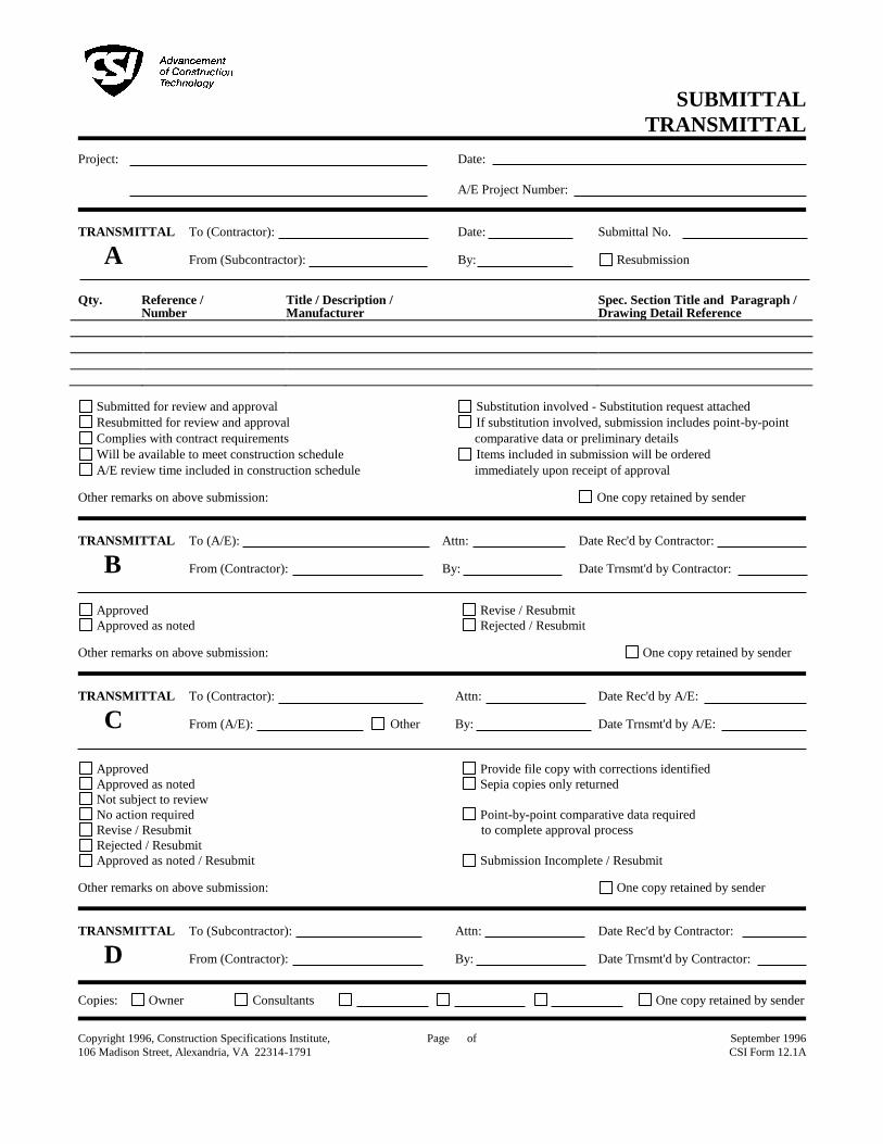
SUBMITTAL
TRANSMITTAL
Project:
Date:
A/E Project Number:
TRANSMITTAL To (Contractor): Date: Submittal No.
A From (Subcontractor): By: Resubmission
Qty. Reference / Title / Description / Spec. Section Title and Paragraph /
Number Manufacturer Drawing Detail Reference
Submitted for review and approval Substitution involved - Substitution request attached
Resubmitted for review and approval If substitution involved, submission includes point-by-point
Complies with contract requirements comparative data or preliminary details
Will be available to meet construction schedule Items included in submission will be ordered
A/E review time included in construction schedule immediately upon receipt of approval Other remarks on above submission: One copy retained by sender
TRANSMITTAL To (A/E): Attn: Date Rec'd by Contractor:
B From (Contractor): By: Date Trnsmt'd by Contractor:
Approved Revise / Resubmit
Approved as noted Rejected / Resubmit Other remarks on above submission: One copy retained by sender
TRANSMITTAL To (Contractor): Attn: Date Rec'd by A/E:
C From (A/E): Other By: Date Trnsmt'd by A/E:
Approved Provide file copy with corrections identified
Approved as noted Sepia copies only returned
Not subject to review
No action required Point-by-point comparative data required
Revise / Resubmit to complete approval process
Rejected / Resubmit
Approved as noted / Resubmit Submission Incomplete / Resubmit Other remarks on above submission: One copy retained by sender
TRANSMITTAL To (Subcontractor): Attn: Date Rec'd by Contractor:
D From (Contractor): By: Date Trnsmt'd by Contractor:
Copies: Owner Consultants One copy retained by sender Copyright 1996, Construction Specifications Institute,
106 Madison Street, Alexandria, VA 22314-1791
Page of
September 1996
CSI Form 12.1A


703 east 1700 south
salt lake city, utah 84105
ph: 801.466.8818
fx: 801.466.4411 1
AGREEMENT CONCERNING DRAWING FILES ON ELECTRONIC MEDIA-CONTRACTOR
At your request, we will provide electronic files for your convenience and use for the project, subject to the
following terms and conditions:
Our electronic files (BIM model or other CAD files) are compatible with REVIT 20___ or AutoCAD 20___. We make
no representation as to the compatibility of these files with your hardware or your software beyond the specified
release of the referred specifications.
Data contained on these electronic files are part of our instruments of service and shall not be used by you or
anyone else receiving these data through or from you for any purpose other than as a convenience for the
referenced project. Any other use or reuse by you or by others will be at your sole risk and without liability or legal
exposure to ajc architects and the consulting engineers for this project. You agree to make no claim and
hereby waive, to the fullest extent permitted by law, any claim or cause of action of any nature against us, our
officers, directors, employees, agents or subconsultants that may arise out of or in connection with your use of
the electronic files.
Furthermore, you shall, to the fullest extent permitted by law, indemnify and hold us harmless against all
damages, liabilities or costs, including reasonable attorneys’ fees and defense costs, arising out of or resulting
from your use of these electronic files.
These electronic files are not construction documents. Differences may exist between these electronic files and
corresponding hard-copy construction documents. We make no representation regarding the accuracy or
completeness of the electronic files you receive. Revit models may not include all design elements necessary for
completing the project. In the event that a conflict arises between the signed or sealed hardcopy construction
documents prepared by ajc architects and consulting engineers, and the electronic files, the signed or sealed
hard-copy construction documents shall govern. You are responsible for determining if any conflict exists. By
your use of these electronic files, you are not relieved of your duty to fully comply with the contract documents,
including, and without limitation, the need to check, confirm and coordinate all dimensions and details, take
field measurements, verify field conditions and coordinate your work with that of other contractors for the
project.
Because information presented on the electronic files can be modified, unintentionally or otherwise, all title
blocks, and other references to ajc architects, our consulting engineers and the owner(s) shall be removed. If
used as submittal documents, submittals will be rejected if non-compliant.
Under no circumstances shall delivery of the electronic files for use by you be deemed a sale by us, and we
make no warranties, either express or implied, of merchantability and fitness for any particular purpose. In no
event shall we be liable for any loss of profit or any consequential damages as a result of your use or reuse of
these electronic files. The drawings files provided by ajc architects and consulting engineers may not be
reproduced or distributed to individuals outside the company or collective organization signing this agreement.
Project Name: ________________________________________
ajc architects Project Number: ________________________________________
List of Revit Models: ________________________________________
List of CAD Files: ________________________________________
Contractor: ________________________________________
Contractor Representative: _________________________________________
Signature: _________________________________________
Date: _________________________________________

ajc architects
703 east 1700 south
salt lake city, utah 84105
ph: 801.466.8818
fx: 801.466.4411
www.ajcarchitects.com
2 of 2 pages
THIS PAGE IS INTENTIONALLY LEFT BLANK

SLCC WESTPOINTE – LEASE BLDG 2150 West Dauntless Avenue
Salt Lake City, Utah 84116
QUALITY REQUIREMENTS 014000 - 1
SECTION 014000 - QUALITY REQUIREMENTS
PART 1 - GENERAL
1.1 RELATED DOCUMENTS
A. Drawings and general provisions of the Contract, including General and
Supplementary Conditions and Division 01 Specification Sections, apply to this Section.
1.2 SUMMARY
A. Section includes administrative and procedural requirements for quality assurance and
quality control.
B. Testing and inspecting services are required to verify compliance with requirements
specified or indicated. These services do not relieve Contractor of responsibility for
compliance with the Contract Document requirements.
1. Specific quality-assurance and -control requirements for individual construction
activities are specified in the Sections that specify those activities. Requirements
in those Sections may also cover production of standard products.
2. Specified tests, inspections, and related actions do not limit Contractor's other
quality-assurance and -control procedures that facilitate compliance with the
Contract Document requirements.
3. Requirements for Contractor to provide quality-assurance and -control services
required by Architect, Owner or authorities having jurisdiction are not limited by
provisions of this Section.
4. Specific test and inspection requirements are not specified in this Section.
1.3 DEFINITIONS
A. Quality-Assurance Services: Activities, actions, and procedures performed before and
during execution of the Work to guard against defects and deficiencies and
substantiate that proposed construction will comply with requirements.
B. Quality-Control Services: Tests, inspections, procedures, and related actions during and
after execution of the Work to evaluate that actual products incorporated into the
Work and completed construction comply with requirements. Services do not include
contract enforcement activities performed by Architect.
C. Mockups: Full-size physical assemblies that are constructed on-site. Mockups are
constructed to verify selections made under Sample submittals; to demonstrate
aesthetic effects and, where indicated, qualities of materials and execution; to review
coordination, testing, or operation; to show interface between dissimilar materials; and
to demonstrate compliance with specified installation tolerances. Mockups are not
Samples. Unless otherwise indicated, approved mockups establish the standard by
which the Work will be judged.

SLCC WESTPOINTE – LEASE BLDG 2150 West Dauntless Avenue
Salt Lake City, Utah 84116
QUALITY REQUIREMENTS 014000 - 2
D. Preconstruction Testing: Tests and inspections performed specifically for Project before
products and materials are incorporated into the Work, to verify performance or
compliance with specified criteria.
E. Product Testing: Tests and inspections that are performed by an NRTL, an NVLAP, or a
testing agency qualified to conduct product testing and acceptable to authorities
having jurisdiction, to establish product performance and compliance with specified
requirements.
F. Source Quality-Control Testing: Tests and inspections that are performed at the source,
e.g., plant, mill, factory, or shop.
G. Field Quality-Control Testing: Tests and inspections that are performed on-site for
installation of the Work and for completed Work.
H. Testing Agency: An entity engaged to perform specific tests, inspections, or both.
Testing laboratory shall mean the same as testing agency.
I. Installer/Applicator/Erector: Contractor or another entity engaged by Contractor as an
employee, Subcontractor, or Sub-subcontractor, to perform a particular construction
operation, including installation, erection, application, and similar operations.
1. Use of trade-specific terminology in referring to a trade or entity does not require
that certain construction activities be performed by accredited or unionized
individuals, or that requirements specified apply exclusively to specific trade(s).
J. Experienced: When used with an entity or individual, "experienced" means having
successfully completed a minimum of five previous projects similar in nature, size, and
extent to this Project; being familiar with special requirements indicated; and having
complied with requirements of authorities having jurisdiction.
1.4 CONFLICTING REQUIREMENTS
A. Referenced Standards: If compliance with two or more standards is specified and the
standards establish different or conflicting requirements for minimum quantities or
quality levels, comply with the most stringent requirement. Refer conflicting
requirements that are different, but apparently equal, to Architect for a decision before
proceeding.
B. Minimum Quantity or Quality Levels: The quantity or quality level shown or specified
shall be the minimum provided or performed. The actual installation may comply
exactly with the minimum quantity or quality specified, or it may exceed the minimum
within reasonable limits. To comply with these requirements, indicated numeric values
are minimum or maximum, as appropriate, for the context of requirements. Refer
uncertainties to Architect for a decision before proceeding.
1.5 ACTION SUBMITTALS
A. Shop Drawings: For mockups, provide plans, sections, and elevations, indicating
materials and size of mockup construction.

SLCC WESTPOINTE – LEASE BLDG 2150 West Dauntless Avenue
Salt Lake City, Utah 84116
QUALITY REQUIREMENTS 014000 - 3
1. Indicate manufacturer and model number of individual components.
2. Provide axonometric drawings for conditions difficult to illustrate in two
dimensions.
1.6 INFORMATIONAL SUBMITTALS
A. Contractor's Statement of Responsibility: When required by authorities having
jurisdiction, submit copy of written statement of responsibility sent to authorities having
jurisdiction before starting work on the following systems:
1. Seismic-force-resisting system, designated seismic system, or component listed in
the designated seismic system quality-assurance plan prepared by Architect.
2. Main wind-force-resisting system or a wind-resisting component listed in the wind-
force-resisting system quality-assurance plan prepared by Architect.
B. Testing Agency Qualifications: For testing agencies specified in "Quality Assurance"
Article to demonstrate their capabilities and experience. Include proof of qualifications
in the form of a recent report on the inspection of the testing agency by a recognized
authority.
C. Schedule of Tests and Inspections: Prepare in tabular form and include the following:
1. Specification Section number and title.
2. Entity responsible for performing tests and inspections.
3. Description of test and inspection.
4. Identification of applicable standards.
5. Identification of test and inspection methods.
6. Number of tests and inspections required.
7. Time schedule or time span for tests and inspections.
8. Requirements for obtaining samples.
9. Unique characteristics of each quality-control service.
1.7 REPORTS AND DOCUMENTS
A. Test and Inspection Reports: Prepare and submit certified written reports specified in
other Sections. Include the following:
1. Date of issue.
2. Project title and number.
3. Name, address, and telephone number of testing agency.
4. Dates and locations of samples and tests or inspections.
5. Names of individuals making tests and inspections.
6. Description of the Work and test and inspection method.
7. Identification of product and Specification Section.
8. Complete test or inspection data.
9. Test and inspection results and an interpretation of test results.
10. Record of temperature and weather conditions at time of sample taking and
testing and inspecting.

SLCC WESTPOINTE – LEASE BLDG 2150 West Dauntless Avenue
Salt Lake City, Utah 84116
QUALITY REQUIREMENTS 014000 - 4
11. Comments or professional opinion on whether tested or inspected Work complies
with the Contract Document requirements.
12. Name and signature of laboratory inspector.
13. Recommendations on retesting and reinspecting.
B. Manufacturer's Technical Representative's Field Reports: Prepare written information
documenting manufacturer's technical representative's tests and inspections specified
in other Sections. Include the following:
1. Name, address, and telephone number of technical representative making
report.
2. Statement on condition of substrates and their acceptability for installation of
product.
3. Statement that products at Project site comply with requirements.
4. Summary of installation procedures being followed, whether they comply with
requirements and, if not, what corrective action was taken.
5. Results of operational and other tests and a statement of whether observed
performance complies with requirements.
6. Statement whether conditions, products, and installation will affect warranty.
7. Other required items indicated in individual Specification Sections.
C. Factory-Authorized Service Representative's Reports: Prepare written information
documenting manufacturer's factory-authorized service representative's tests and
inspections specified in other Sections. Include the following:
1. Name, address, and telephone number of factory-authorized service
representative making report.
2. Statement that equipment complies with requirements.
3. Results of operational and other tests and a statement of whether observed
performance complies with requirements.
4. Statement whether conditions, products, and installation will affect warranty.
5. Other required items indicated in individual Specification Sections.
D. Permits, Licenses, and Certificates: For Owner's records, submit copies of permits,
licenses, certifications, inspection reports, releases, jurisdictional settlements, notices,
receipts for fee payments, judgments, correspondence, records, and similar
documents, established for compliance with standards and regulations bearing on
performance of the Work.
1.8 QUALITY ASSURANCE
A. General: Qualifications paragraphs in this article establish the minimum qualification
levels required; individual Specification Sections specify additional requirements.
B. Manufacturer Qualifications: A firm experienced in manufacturing products or systems
similar to those indicated for this Project and with a record of successful in-service
performance, as well as sufficient production capacity to produce required units.

SLCC WESTPOINTE – LEASE BLDG 2150 West Dauntless Avenue
Salt Lake City, Utah 84116
QUALITY REQUIREMENTS 014000 - 5
C. Fabricator Qualifications: A firm experienced in producing products similar to those
indicated for this Project and with a record of successful in-service performance, as well
as sufficient production capacity to produce required units.
D. Installer Qualifications: A firm or individual experienced in installing, erecting, or
assembling work similar in material, design, and extent to that indicated for this Project,
whose work has resulted in construction with a record of successful in-service
performance.
E. Professional Engineer Qualifications: A professional engineer who is legally qualified to
practice in jurisdiction where Project is located and who is experienced in providing
engineering services of the kind indicated. Engineering services are defined as those
performed for installations of the system, assembly, or product that are similar in
material, design, and extent to those indicated for this Project.
F. Specialists: Certain Specification Sections require that specific construction activities
shall be performed by entities who are recognized experts in those operations.
Specialists shall satisfy qualification requirements indicated and shall be engaged for
the activities indicated.
1. Requirements of authorities having jurisdiction shall supersede requirements for
specialists.
G. Testing Agency Qualifications: An NRTL, an NVLAP, or an independent agency with the
experience and capability to conduct testing and inspecting indicated, as
documented according to ASTM E 329; and with additional qualifications specified in
individual Sections; and, where required by authorities having jurisdiction, that is
acceptable to authorities.
1. NRTL: A nationally recognized testing laboratory according to 29 CFR 1910.7.
2. NVLAP: A testing agency accredited according to NIST's National Voluntary
Laboratory Accreditation Program.
H. Manufacturer's Technical Representative Qualifications: An authorized representative
of manufacturer who is trained and approved by manufacturer to observe and inspect
installation of manufacturer's products that are similar in material, design, and extent to
those indicated for this Project.
I. Factory-Authorized Service Representative Qualifications: An authorized representative
of manufacturer who is trained and approved by manufacturer to inspect installation of
manufacturer's products that are similar in material, design, and extent to those
indicated for this Project.
J. Preconstruction Testing: Where testing agency is indicated to perform preconstruction
testing for compliance with specified requirements for performance and test methods,
comply with the following:
1. Contractor responsibilities include the following:
a. Provide test specimens representative of proposed products and
construction.

SLCC WESTPOINTE – LEASE BLDG 2150 West Dauntless Avenue
Salt Lake City, Utah 84116
QUALITY REQUIREMENTS 014000 - 6
b. Submit specimens in a timely manner with sufficient time for testing and
analyzing results to prevent delaying the Work.
c. Provide sizes and configurations of test assemblies, mockups, and
laboratory mockups to adequately demonstrate capability of products to
comply with performance requirements.
d. Build site-assembled test assemblies and mockups using installers who will
perform same tasks for Project.
e. Build laboratory mockups at testing facility using personnel, products, and
methods of construction indicated for the completed Work.
f. When testing is complete, remove test specimens, assemblies,
and mockups; do not reuse products on Project.
2. Testing Agency Responsibilities: Submit a certified written report of each test,
inspection, and similar quality-assurance service to Architect with copy to
Contractor. Interpret tests and inspections and state in each report whether
tested and inspected work complies with or deviates from the Contract
Documents.
K. Mockups: Before installing portions of the Work requiring mockups, build mockups for
each form of construction and finish required to comply with the following
requirements, using materials indicated for the completed Work:
1. Build mockups in location and of size indicated or, if not indicated, as directed by
Architect.
2. Notify Architect seven days in advance of dates and times when mockups will be
constructed.
3. Employ supervisory personnel who will oversee mockup construction. Employ
workers that will be employed during the construction at Project.
4. Demonstrate the proposed range of aesthetic effects and workmanship.
5. Obtain Architect's approval of mockups before starting work, fabrication, or
construction.
a. Allow up to seven days for initial review and each re-review of each
mockup.
6. Maintain mockups during construction in an undisturbed condition as a standard
for judging the completed Work.
7. Demolish and remove mockups when directed unless otherwise indicated.
1.9 QUALITY CONTROL
A. Owner Responsibilities: Owner will engage a qualified testing agency to perform these
services.
1. Owner will furnish Contractor with names, addresses, and telephone numbers of
testing agencies engaged and a description of types of testing and inspecting
they are engaged to perform.
2. Payment for these services will be made from testing and inspecting allowances,
as authorized by Change Orders.

SLCC WESTPOINTE – LEASE BLDG 2150 West Dauntless Avenue
Salt Lake City, Utah 84116
QUALITY REQUIREMENTS 014000 - 7
3. Costs for retesting and reinspecting construction that replaces or is necessitated
by work that failed to comply with the Contract Documents will be charged to
Contractor, and the Contract Sum will be adjusted by Change Order.
B. Contractor Responsibilities: Tests and inspections not explicitly assigned to Owner are
Contractor's responsibility. Perform additional quality-control activities required to verify
that the Work complies with requirements, whether specified or not.
1. Unless otherwise indicated, provide quality-control services specified and those
required by authorities having jurisdiction. Perform quality-control services
required of Contractor by authorities having jurisdiction, whether specified or not.
2. Where services are indicated as Contractor's responsibility, engage a qualified
testing agency to perform these quality-control services.
a. Contractor shall not employ same entity engaged by Owner, unless agreed
to in writing by Owner.
3. Notify testing agencies at least 24 hours in advance of time when Work that
requires testing or inspecting will be performed.
4. Where quality-control services are indicated as Contractor's responsibility, submit
a certified written report, in duplicate, of each quality-control service.
5. Testing and inspecting requested by Contractor and not required by the
Contract Documents are Contractor's responsibility.
6. Submit additional copies of each written report directly to authorities having
jurisdiction, when they so direct.
C. Manufacturer's Field Services: Where indicated, engage a factory-authorized service
representative to inspect field-assembled components and equipment installation,
including service connections. Report results in writing as specified in Section 013300
"Submittal Procedures."
D. Manufacturer's Technical Services: Where indicated, engage a manufacturer's
technical representative to observe and inspect the Work. Manufacturer's technical
representative's services include participation in preinstallation conferences,
examination of substrates and conditions, verification of materials, observation of
Installer activities, inspection of completed portions of the Work, and submittal of written
reports.
E. Retesting/Reinspecting: Regardless of whether original tests or inspections were
Contractor's responsibility, provide quality-control services, including retesting and
reinspecting, for construction that replaced Work that failed to comply with the
Contract Documents.
F. Testing Agency Responsibilities: Cooperate with Architect and Contractor in
performance of duties. Provide qualified personnel to perform required tests and
inspections.
1. Notify Architect and Contractor promptly of irregularities or deficiencies observed
in the Work during performance of its services.
2. Determine the location from which test samples will be taken and in which in-situ
tests are conducted.

SLCC WESTPOINTE – LEASE BLDG 2150 West Dauntless Avenue
Salt Lake City, Utah 84116
QUALITY REQUIREMENTS 014000 - 8
3. Conduct and interpret tests and inspections and state in each report whether
tested and inspected work complies with or deviates from requirements.
4. Submit a certified written report, in duplicate, of each test, inspection, and similar
quality-control service through Contractor.
5. Do not release, revoke, alter, or increase the Contract Document requirements or
approve or accept any portion of the Work.
6. Do not perform any duties of Contractor.
G. Associated Services: Cooperate with agencies performing required tests, inspections,
and similar quality-control services, and provide reasonable auxiliary services as
requested. Notify agency sufficiently in advance of operations to permit assignment of
personnel. Provide the following:
1. Access to the Work.
2. Incidental labor and facilities necessary to facilitate tests and inspections.
3. Adequate quantities of representative samples of materials that require testing
and inspecting. Assist agency in obtaining samples.
4. Facilities for storage and field curing of test samples.
5. Delivery of samples to testing agencies.
6. Preliminary design mix proposed for use for material mixes that require control by
testing agency.
7. Security and protection for samples and for testing and inspecting equipment at
Project site.
H. Coordination: Coordinate sequence of activities to accommodate required quality-
assurance and -control services with a minimum of delay and to avoid necessity of
removing and replacing construction to accommodate testing and inspecting.
1. Schedule times for tests, inspections, obtaining samples, and similar activities.
I. Schedule of Tests and Inspections: Prepare a schedule of tests, inspections, and similar
quality-control services required by the Contract Documents. Coordinate and submit
concurrently with Contractor's construction schedule. Update as the Work progresses.
1. Distribution: Distribute schedule to Owner, Architect testing agencies, and each
party involved in performance of portions of the Work where tests and inspections
are required.
1.10 SPECIAL TESTS AND INSPECTIONS
A. Special Tests and Inspections: Owner will engage a qualified special inspector to
conduct special tests and inspections required by authorities having jurisdiction as the
responsibility of Owner as follows:
B. Special Tests and Inspections: Conducted by a qualified special inspector as required
by authorities having jurisdiction, as indicated in individual Specification and as follows:
1. Verifying that manufacturer maintains detailed fabrication and quality-control
procedures and reviews the completeness and adequacy of those procedures
to perform the Work.

SLCC WESTPOINTE – LEASE BLDG 2150 West Dauntless Avenue
Salt Lake City, Utah 84116
QUALITY REQUIREMENTS 014000 - 9
2. Notifying Architect and Contractor promptly of irregularities and deficiencies
observed in the Work during performance of its services.
3. Submitting a certified written report of each test, inspection, and similar quality-
control service to Architect with copy to Contractor and to authorities having
jurisdiction.
4. Submitting a final report of special tests and inspections at Substantial
Completion, which includes a list of unresolved deficiencies.
5. Interpreting tests and inspections and stating in each report whether tested and
inspected work complies with or deviates from the Contract Documents.
6. Retesting and reinspecting corrected work.
PART 2 - PRODUCTS (Not Used)
PART 3 - EXECUTION
3.1 ACCEPTABLE TESTING AGENCIES
A. Provide, testing Agency to be acceptable to the Authorities having Jurisdiction,
including and submit and provide City Special Inspection Form Lists.
3.2 TEST AND INSPECTION LOG
A. Test and Inspection Log: Prepare a record of tests and inspections. Include the
following:
1. Date test or inspection was conducted.
2. Description of the Work tested or inspected.
3. Date test or inspection results were transmitted to Architect.
4. Identification of testing agency or special inspector conducting test or inspection.
B. Maintain log at Project site. Post changes and revisions as they occur. Provide access
to test and inspection log for Architect's reference during normal working hours.
3.3 REPAIR AND PROTECTION
A. General: On completion of testing, inspecting, sample taking, and similar services,
repair damaged construction and restore substrates and finishes.
1. Provide materials and comply with installation requirements specified in other
Specification Sections or matching existing substrates and finishes. Restore
patched areas and extend restoration into adjoining areas with durable seams
that are as invisible as possible. Comply with the Contract Document
requirements for cutting and patching in Section 017300 "Execution."
B. Protect construction exposed by or for quality-control service activities.

SLCC WESTPOINTE – LEASE BLDG 2150 West Dauntless Avenue
Salt Lake City, Utah 84116
QUALITY REQUIREMENTS 014000 - 10
C. Repair and protection are Contractor's responsibility, regardless of the assignment of
responsibility for quality-control services.
END OF SECTION 014000

SLCC WESTPOINTE – LEASE BLDG 2150 West Dauntless Avenue
Salt Lake City, Utah 84116
TEMPORARY FACILITIES AND CONTROLS 015000 - 1
SECTION 015000 - TEMPORARY FACILITIES AND CONTROLS
PART 1 - GENERAL
1.1 RELATED DOCUMENTS
A. Drawings and general provisions of the Contract, including General and Supplementary
Conditions and other Division 01 Specification Sections, apply to this Section.
1.2 SUMMARY
A. The space under construction is to be where the General contractor may set-up a temporary
office; coordinate with the schedule.
1.3 PROJECT CONDITIONS
A. Conditions of Use: The following conditions apply to use of temporary services and facilities by
all parties engaged in the Work:
1. Keep temporary services and facilities clean and neat (water, sewer and sanitary
facilities. Do not us existing facilities for construction waste.
2. Relocate temporary services and facilities as required by progress of the Work.
PART 2 - PRODUCTS
2.1 MATERIALS
A. General: Provide new materials. Undamaged, previously used materials in serviceable
condition may be used if approved by Architect. Provide materials suitable for use intended.
2.2 EQUIPMENT
A. General: Provide equipment suitable for use intended.
B. Fire Extinguishers: Hand carried, portable, UL rated. Provide class and extinguishing agent as
indicated or a combination of extinguishers of NFPA-recommended classes for exposures.
1. Comply with NFPA 10 and NFPA 241 for classification, extinguishing agent, and size
required by location and class of fire exposure.
C. Drinking-Water Fixtures: Containerized, tap-dispenser, bottled-water drinking-water units,
including paper cup supply.
1. Where power is accessible, provide electric water coolers to maintain dispensed water
temperature at 45 to 55 deg F (7.2 to 12.7 deg C).

SLCC WESTPOINTE – LEASE BLDG 2150 West Dauntless Avenue
Salt Lake City, Utah 84116
TEMPORARY FACILITIES AND CONTROLS 015000 - 2
D. Electrical Outlets: Properly configured, NEMA-polarized outlets to prevent insertion of 110- to
120-V plugs into higher-voltage outlets; equipped with ground-fault circuit interrupters, reset
button, and pilot light.
E. Power Distribution System Circuits: Existing power at the tenant space may be used if
available.
PART 3 - EXECUTION
3.1 TEMPORARY UTILITY INSTALLATION
A. Ventilation and Humidity Control: Provide temporary ventilation required by construction
activities for curing or drying of completed installations or for protecting installed construction
from adverse effects of high humidity. Select equipment from that specified that will not have
a harmful effect on completed installations or elements being installed. Coordinate ventilation
requirements to produce ambient condition required and minimize energy consumption.
B. Lighting: Provide temporary lighting with local switching that provides adequate illumination for
construction operations and traffic conditions.
C. Telephone Service: Provide cell phone service
1. Provide a portable cellular telephone for superintendent's use in making and receiving
telephone calls when away from field office.
3.2 SUPPORT FACILITIES INSTALLATION
A. General: Comply with the following:
1. Locate construction staging and other temporary construction and support facilities for
easy access and as directed by the building management requirements and approved
locations.
2. Maintain support facilities until near Substantial Completion. Remove before Substantial
Completion. Personnel remaining after Substantial Completion will be permitted to use
permanent facilities, under conditions acceptable to Tenant.
B. Traffic Controls: Provide temporary traffic controls at junction of roads with public roads.
Include warning signs for public traffic and "STOP" signs for entrance onto public roads.
Comply with requirements of authorities having jurisdiction.
C. Project Identification and Temporary Signs: not allowed on this project.
D. Waste Disposal Facilities: Provide waste-collection containers in sizes adequate to handle
waste from construction operations. Revise three subparagraphs below to suit Project or
delete all.

SLCC WESTPOINTE – LEASE BLDG 2150 West Dauntless Avenue
Salt Lake City, Utah 84116
TEMPORARY FACILITIES AND CONTROLS 015000 - 3
3.3 SECURITY AND PROTECTION FACILITIES INSTALLATION
A. Barricades, Warning Signs, and Lights: Comply with standards and code requirements for
erecting structurally adequate barricades. Paint with appropriate colors, graphics, and
warning signs to inform personnel and public of possible hazard. Where appropriate and
needed, provide lighting, including flashing red or amber lights.
3.4 OPERATION, TERMINATION, AND REMOVAL
A. Supervision: Enforce strict discipline in use of temporary facilities. To minimize waste and
abuse, limit availability of temporary facilities to essential and intended uses.
B. Maintenance: Maintain facilities in good operating condition until removal.
1. At Substantial Completion, clean and renovate all areas used during construction
period. Comply with final cleaning requirements in Division 01 Section "Closeout
Procedures."
END OF SECTION 01500

SLCC WESTPOINTE – LEASE BLDG 2150 West Dauntless Avenue
Salt Lake City, Utah 84116
TEMPORARY FACILITIES AND CONTROLS 015000 - 4
THIS PAGE IS INTENTIONALLY LEFT BLANK
SLCC WESTPOINTE – LEASE BLDG 2150 West Dauntless Avenue
Salt Lake City, Utah 84116
PRODUCT REQUIREMENTS 016000 - 1
SECTION 016000 - PRODUCT REQUIREMENTS
PART 1 - GENERAL
1.1 RELATED DOCUMENTS
A. Drawings and general provisions of the Contract, including General and
Supplementary Conditions and Division 01 Specification Sections, apply to this Section.
1.2 SUMMARY
A. Section includes administrative and procedural requirements for selection of products
for use in Project; product delivery, storage, and handling; manufacturers' standard
warranties on products; special warranties; and comparable products.
B. Related Requirements:
1. Section 012500 "Substitution Procedures" for requests for substitutions.
1.3 DEFINITIONS
A. Products: Items obtained for incorporating into the Work, whether purchased for
Project or taken from previously purchased stock. The term "product" includes the terms
"material," "equipment," "system," and terms of similar intent.
1. Named Products: Items identified by manufacturer's product name, including
make or model number or other designation shown or listed in manufacturer's
published product literature, that is current as of date of the Contract
Documents.
2. New Products: Items that have not previously been incorporated into another
project or facility. Products salvaged or recycled from other projects are not
considered new products.
3. Comparable Product: Product that is demonstrated and approved through
submittal process to have the indicated qualities related to type, function,
dimension, in-service performance, physical properties, appearance, and other
characteristics that equal or exceed those of specified product.
B. Basis-of-Design Product Specification: A specification in which a specific
manufacturer's product is named and accompanied by the words "basis-of-design,"
including make or model number or other designation, to establish the significant
qualities related to type, function, dimension, in-service performance, physical
properties, appearance, and other characteristics for purposes of evaluating
comparable products of additional manufacturers named in the specification.

SLCC WESTPOINTE – LEASE BLDG 2150 West Dauntless Avenue
Salt Lake City, Utah 84116
PRODUCT REQUIREMENTS 016000 - 2
1.4 ACTION SUBMITTALS
A. Comparable Product Requests: Submit request for consideration of each comparable
product. Identify product or fabrication or installation method to be replaced. Include
Specification Section number and title and Drawing numbers and titles.
1. Include data to indicate compliance with the requirements specified in
"Comparable Products" Article.
2. Architect's Action: If necessary, Architect will request additional information or
documentation for evaluation within one week of receipt of a comparable
product request. Architect will notify Contractor of approval or rejection of
proposed comparable product request within 7 days of receipt of request, or
seven days of receipt of additional information or documentation, whichever is
later.
a. Form of Approval: As specified in Section 013300 "Submittal Procedures."
b. Use product specified if Architect does not issue a decision on use of a
comparable product request within time allocated.
B. Basis-of-Design Product Specification Submittal: Comply with requirements in
Section 013300 "Submittal Procedures." Show compliance with requirements.
1.5 QUALITY ASSURANCE
A. Compatibility of Options: If Contractor is given option of selecting between two or
more products for use on Project, select product compatible with specification
requirements.
1. Each contractor is responsible for providing products and construction methods
compatible with products and construction methods of other contractors.
2. If a dispute arises between contractors over concurrently selectable but
incompatible products, Architect will determine which products shall be used.
1.6 PRODUCT DELIVERY, STORAGE, AND HANDLING
A. Deliver, store, and handle products using means and methods that will prevent
damage, deterioration, and loss, including theft and vandalism. Comply with
manufacturer's written instructions.
B. Delivery and Handling:
1. Schedule delivery to minimize long-term storage at Project site and to prevent
overcrowding of construction spaces.
2. Coordinate delivery with installation time to ensure minimum holding time for
items that are flammable, hazardous, easily damaged, or sensitive to
deterioration, theft, and other losses.
3. Deliver products to Project site in an undamaged condition in manufacturer's
original sealed container or other packaging system, complete with labels and
instructions for handling, storing, unpacking, protecting, and installing.

SLCC WESTPOINTE – LEASE BLDG 2150 West Dauntless Avenue
Salt Lake City, Utah 84116
PRODUCT REQUIREMENTS 016000 - 3
4. Inspect products on delivery to determine compliance with the Contract
Documents and to determine that products are undamaged and properly
protected.
C. Storage:
1. Store products to allow for inspection and measurement of quantity or counting
of units.
2. Store materials in a manner that will not endanger Project structure.
3. Store products that are subject to damage by the elements, under cover in a
weathertight enclosure above ground, with ventilation adequate to prevent
condensation.
4. Protect foam plastic from exposure to sunlight, except to extent necessary for
period of installation and concealment.
5. Comply with product manufacturer's written instructions for temperature,
humidity, ventilation, and weather-protection requirements for storage.
6. Protect stored products from damage and liquids from freezing.
7. Provide a secure location and enclosure at Project site for storage of materials
and equipment by Owner's construction forces. Coordinate location with Owner.
1.7 PRODUCT WARRANTIES
A. Warranties specified in other Sections shall be in addition to, and run concurrent with,
other warranties required by the Contract Documents. Manufacturer's disclaimers and
limitations on product warranties do not relieve Contractor of obligations under
requirements of the Contract Documents.
1. Manufacturer's Warranty: Written warranty furnished by individual manufacturer
for a particular product and specifically endorsed by manufacturer to Owner.
2. Special Warranty: Written warranty required by the Contract Documents to
provide specific rights for Owner.
B. Special Warranties: Prepare a written document that contains appropriate terms and
identification, ready for execution.
1. Manufacturer's Standard Form: Modified to include Project-specific information
and properly executed.
2. Specified Form: When specified forms are included with the Specifications,
prepare a written document using indicated form properly executed.
3. See other Sections for specific content requirements and particular requirements
for submitting special warranties.
C. Submittal Time: Comply with requirements in Section 017700 "Closeout Procedures."

SLCC WESTPOINTE – LEASE BLDG 2150 West Dauntless Avenue
Salt Lake City, Utah 84116
PRODUCT REQUIREMENTS 016000 - 4
PART 2 - PRODUCTS
2.1 PRODUCT SELECTION PROCEDURES
A. General Product Requirements: Provide products that comply with the Contract
Documents, are undamaged and, unless otherwise indicated, are new at time of
installation.
1. Provide products complete with accessories, trim, finish, fasteners, and other
items needed for a complete installation and indicated use and effect.
2. Standard Products: If available, and unless custom products or nonstandard
options are specified, provide standard products of types that have been
produced and used successfully in similar situations on other projects.
3. Owner reserves the right to limit selection to products with warranties not in
conflict with requirements of the Contract Documents.
4. Where products are accompanied by the term "as selected," Architect will make
selection.
5. Descriptive, performance, and reference standard requirements in the
Specifications establish salient characteristics of products.
6. Or Equal: For products specified by name and accompanied by the term "or
equal," or "or approved equal," “equivalent” or "or approved," comply with
requirements in "Comparable Products" Article to obtain approval for use of an
unnamed product.
B. Product Selection Procedures:
1. Product: Where Specifications name a single manufacturer and product,
provide the named product that complies with requirements. Comparable
products or substitutions for Contractor's convenience will not be considered.
2. Manufacturer/Source: Where Specifications name a single manufacturer or
source, provide a product by the named manufacturer or source that complies
with requirements. Comparable products or substitutions for Contractor's
convenience will not be considered.
3. Products:
a. Restricted List: Where Specifications include a list of names of both
manufacturers and products, provide one of the products listed that
complies with requirements. Comparable products or substitutions for
Contractor's convenience will no be considered unless otherwise indicated.
b. Nonrestricted List: Where Specifications include a list of names of both
available manufacturers and products, provide one of the products listed,
or an unnamed product, that complies with requirements. Comply with
requirements in "Comparable Products" Article for consideration of an
unnamed product.
4. Manufacturers:
a. Restricted List: Where Specifications include a list of manufacturers' names,
provide a product by one of the manufacturers listed that complies with
SLCC WESTPOINTE – LEASE BLDG 2150 West Dauntless Avenue
Salt Lake City, Utah 84116
PRODUCT REQUIREMENTS 016000 - 5
requirements. Comparable products or substitutions for Contractor's
convenience will not be considered unless otherwise indicated.
b. Nonrestricted List: Where Specifications include a list of available
manufacturers, provide a product by one of the manufacturers listed, or a
product by an unnamed manufacturer, that complies with requirements.
Comply with requirements in "Comparable Products" Article for
consideration of an unnamed manufacturer's product.
5. Basis-of-Design Product: Where Specifications name a product, or refer to a
product indicated on Drawings, and include a list of manufacturers, provide the
specified or indicated product or a comparable product by one of the other
named manufacturers. Drawings and Specifications indicate sizes, profiles,
dimensions, and other characteristics that are based on the product named.
Comply with requirements in "Comparable Products" Article for consideration of
an unnamed product by one of the other named manufacturers.
C. Visual Matching Specification: Where Specifications require "match Architect's
sample", provide a product that complies with requirements and matches Architect's
sample. Architect's decision will be final on whether a proposed product matches.
1. If no product available within specified category matches and complies with
other specified requirements, comply with requirements in Section 012500
"Substitution Procedures" for proposal of product.
D. Visual Selection Specification: Where Specifications include the phrase "as selected by
Architect from manufacturer's full range" or similar phrase, select a product that
complies with requirements. Architect will select color, gloss, pattern, density, or texture
from manufacturer's product line that includes both standard and premium items.
2.2 COMPARABLE PRODUCTS
A. Conditions for Consideration: Architect will consider Contractor's request for
comparable product when the following conditions are satisfied. If the following
conditions are not satisfied, Architect may return requests without action, except to
record noncompliance with these requirements:
1. Evidence that the proposed product does not require revisions to the Contract
Documents, that it is consistent with the Contract Documents and will produce
the indicated results, and that it is compatible with other portions of the Work.
2. Detailed comparison of significant qualities of proposed product with those
named in the Specifications. Significant qualities include attributes such as
performance, weight, size, durability, visual effect, and specific features and
requirements indicated.
3. Evidence that proposed product provides specified warranty.
4. List of similar installations for completed projects with project names and
addresses and names and addresses of architects and owners, if requested.
5. Samples, if requested.

SLCC WESTPOINTE – LEASE BLDG 2150 West Dauntless Avenue
Salt Lake City, Utah 84116
PRODUCT REQUIREMENTS 016000 - 6
PART 3 - EXECUTION (Not Used)
END OF SECTION 016000

SLCC WESTPOINTE – LEASE BLDG 2150 West Dauntless Avenue
Salt Lake City, Utah 84116
EXECUTION 017300 - 1
SECTION 017300 - EXECUTION
PART 1 - GENERAL
1.1 RELATED DOCUMENTS
A. Drawings and general provisions of the Contract, including General and
Supplementary Conditions and other Division 01 Specification Sections, apply to this
Section.
1.2 SUMMARY
A. Section includes general administrative and procedural requirements governing
execution of the Work including, but not limited to, the following:
1. Construction layout.
2. Installation of the Work.
3. Coordination of Owner-installed products.
4. Progress cleaning.
5. Protection of installed construction.
6. Correction of the Work.
B. Related Sections:
1. Section 013300 "Submittal Procedures" for submitting surveys.
2. Section 017700 "Closeout Procedures" for submitting final property survey with
Project Record Documents, recording of Owner-accepted deviations from
indicated lines and levels, and final cleaning.
1.3 DEFINITIONS
A. Cutting: Removal of in-place construction necessary to permit installation or
performance of other work.
B. Patching: Fitting and repair work required to restore construction to original conditions
after installation of other work.
1.4 INFORMATIONAL SUBMITTALS
A. Qualification Data: For land surveyor or professional engineer.
B. Landfill Receipts: Submit copy of receipts issued by a landfill facility, licensed to accept
hazardous materials, for hazardous waste disposal.

SLCC WESTPOINTE – LEASE BLDG 2150 West Dauntless Avenue
Salt Lake City, Utah 84116
EXECUTION 017300 - 2
1.5 QUALITY ASSURANCE
A. Cutting and Patching: Comply with requirements for and limitations on cutting and
patching of construction elements.
1. Structural Elements: When cutting and patching structural elements, notify
Architect of locations and details of cutting and await directions from the
Architect before proceeding. Shore, brace, and support structural element
during cutting and patching. Do not cut and patch structural elements in a
manner that could change their load-carrying capacity or increase deflection.
2. Operational Elements: Do not cut and patch operating elements and related
components in a manner that results in reducing their capacity to perform as
intended or that results in increased maintenance or decreased operational life
or safety. Operational elements include the following:
a. Primary operational systems and equipment.
b. Fire separation assemblies.
c. Air or smoke barriers.
d. Fire-suppression systems.
e. Mechanical systems piping and ducts.
f. Control systems.
g. Communication systems.
h. Conveying systems.
i. Electrical wiring systems.
j. Operating systems of special construction.
3. Other Construction Elements: Do not cut and patch other construction elements
or components in a manner that could change their load-carrying capacity, that
results in reducing their capacity to perform as intended, or that results in
increased maintenance or decreased operational life or safety. Other
construction elements include but are not limited to the following:
a. Water, moisture, or vapor barriers.
b. Membranes and flashings.
c. Equipment supports.
d. Piping, ductwork, vessels, and equipment.
e. Noise- and vibration-control elements and systems.
4. Visual Elements: Do not cut and patch construction in a manner that results in
visual evidence of cutting and patching. Do not cut and patch exposed
construction in a manner that would, in Architect's opinion, reduce the building's
aesthetic qualities. Remove and replace construction that has been cut and
patched in a visually unsatisfactory manner.
B. Cutting and Patching Conference: Before proceeding, meet at Project site with parties
involved in cutting and patching, including mechanical and electrical trades. Review
areas of potential interference and conflict. Coordinate procedures and resolve
potential conflicts before proceeding.

SLCC WESTPOINTE – LEASE BLDG 2150 West Dauntless Avenue
Salt Lake City, Utah 84116
EXECUTION 017300 - 3
C. Manufacturer's Installation Instructions: Obtain and maintain on-site manufacturer's
written recommendations and instructions for installation of products and equipment.
PART 2 - PRODUCTS
2.1 MATERIALS
A. General: Comply with requirements specified in other Sections.
1. For projects requiring compliance with sustainable design and construction
practices and procedures, utilize products for patching that comply with
requirements of Sustainable Design materials.
B. In-Place Materials: Use materials for patching identical to in-place materials. For
exposed surfaces, use materials that visually match in-place adjacent surfaces to the
fullest extent possible.
1. If identical materials are unavailable or cannot be used, use materials that, when
installed, will provide a match acceptable to the Architect for the visual and
functional performance of in-place materials.
PART 3 - EXECUTION
3.1 EXAMINATION
A. Existing Conditions: The existence and location of underground and other utilities and
construction indicated as existing are not guaranteed. Before beginning sitework,
investigate and verify the existence and location of underground utilities, and electrical
systems, and other construction affecting the Work.
1. Before construction, verify the location and invert elevation at points of
connection of sanitary sewer, storm sewer, and water-service piping;
underground electrical services, and other utilities.
2. Furnish location data for work related to Project that must be performed by
public utilities serving Project site.
B. Examination and Acceptance of Conditions: Before proceeding with each
component of the Work, examine substrates, areas, and conditions, with Installer or
Applicator present where indicated, for compliance with requirements for installation
tolerances and other conditions affecting performance. Record observations.
1. Written Report: Where a written report listing conditions detrimental to
performance of the Work is required by other Sections, include the following:
a. Description of the Work.
b. List of detrimental conditions, including substrates.
c. List of unacceptable installation tolerances.
d. Recommended corrections.

SLCC WESTPOINTE – LEASE BLDG 2150 West Dauntless Avenue
Salt Lake City, Utah 84116
EXECUTION 017300 - 4
2. Verify compatibility with and suitability of substrates, including compatibility with
existing finishes or primers.
3. Examine roughing-in for mechanical and electrical systems to verify actual
locations of connections before equipment and fixture installation.
4. Examine walls, floors, and roofs for suitable conditions where products and
systems are to be installed.
5. Proceed with installation only after unsatisfactory conditions have been
corrected. Proceeding with the Work indicates acceptance of surfaces and
conditions.
3.2 PREPARATION
A. Existing Utility Information: Furnish information to local utility and Owner that is necessary
to adjust, move, or relocate existing utility structures, utility poles, lines, services, or other
utility appurtenances located in or affected by construction. Coordinate with
authorities having jurisdiction.
B. Field Measurements: Take field measurements as required to fit the Work properly.
Recheck measurements before installing each product. Where portions of the Work
are indicated to fit to other construction, verify dimensions of other construction by field
measurements before fabrication. Coordinate fabrication schedule with construction
progress to avoid delaying the Work.
C. Space Requirements: Verify space requirements and dimensions of items shown
diagrammatically on Drawings.
D. Review of Contract Documents and Field Conditions: Immediately on discovery of the
need for clarification of the Contract Documents caused by differing field conditions
outside the control of the Contractor, submit a request for information to Architect
according to requirements in Division 01 Section "Project Management and
Coordination."
3.3 CONSTRUCTION LAYOUT
A. Verification: Before proceeding to lay out the Work, verify layout information shown on
Drawings. If discrepancies are discovered, notify Architect promptly.
B. General: Lay out the Work using accepted surveying practices.
1. Establish dimensions within tolerances indicated. Do not scale Drawings to obtain
required dimensions.
2. Inform installers of lines and levels to which they must comply.
3. Check the location, level and plumb, of every major element as the Work
progresses.
4. Notify Architect when deviations from required lines and levels exceed allowable
tolerances.

SLCC WESTPOINTE – LEASE BLDG 2150 West Dauntless Avenue
Salt Lake City, Utah 84116
EXECUTION 017300 - 5
3.4 INSTALLATION
A. General: Locate the Work and components of the Work accurately, in correct
alignment and elevation, as indicated.
1. Make vertical work plumb and make horizontal work level.
2. Where space is limited, install components to maximize space available for
maintenance and ease of removal for replacement.
3. Conceal pipes and wiring in finished areas, unless otherwise indicated.
B. Comply with manufacturer's written instructions and recommendations for installing
products in applications indicated.
C. Install products at the time and under conditions that will ensure the best possible
results. Maintain conditions required for product performance until Substantial
Completion.
D. Conduct construction operations so no part of the Work is subjected to damaging
operations or loading in excess of that expected during normal conditions of
occupancy.
E. Tools and Equipment: Do not use tools or equipment that produce harmful noise levels.
F. Templates: Obtain and distribute to the parties involved templates for work specified to
be factory prepared and field installed. Check Shop Drawings of other work to confirm
that adequate provisions are made for locating and installing products to comply with
indicated requirements.
G. Attachment: Provide blocking and attachment plates and anchors and fasteners of
adequate size and number to securely anchor each component in place, accurately
located and aligned with other portions of the Work. Where size and type of
attachments are not indicated, verify size and type required for load conditions.
1. Mounting Heights: Where mounting heights are not indicated, mount
components at heights directed by Architect.
2. Allow for building movement, including thermal expansion and contraction.
3. Coordinate installation of anchorages. Furnish setting drawings, templates, and
directions for installing anchorages, including sleeves, concrete inserts, anchor
bolts, and items with integral anchors, that are to be embedded in concrete or
masonry. Deliver such items to Project site in time for installation.
H. Joints: Make joints of uniform width. Where joint locations in exposed work are not
indicated, arrange joints for the best visual effect. Fit exposed connections together to
form hairline joints.
I. Hazardous Materials: Use products, cleaners, and installation materials that are not
considered hazardous.

SLCC WESTPOINTE – LEASE BLDG 2150 West Dauntless Avenue
Salt Lake City, Utah 84116
EXECUTION 017300 - 6
3.5 CUTTING AND PATCHING
A. Cutting and Patching, General: Employ skilled workers to perform cutting and
patching. Proceed with cutting and patching at the earliest feasible time, and
complete without delay.
1. Cut in-place construction to provide for installation of other components or
performance of other construction, and subsequently patch as required to
restore surfaces to their original condition.
B. Temporary Support: Provide temporary support of work to be cut.
C. Protection: Protect in-place construction during cutting and patching to prevent
damage. Provide protection from adverse weather conditions for portions of Project
that might be exposed during cutting and patching operations.
D. Adjacent Occupied Areas: Where interference with use of adjoining areas or
interruption of free passage to adjoining areas is unavoidable, coordinate cutting and
patching in accordance with requirements of Division 01 Section "Summary."
E. Existing Utility Services and Mechanical/Electrical Systems: Where existing
services/systems are required to be removed, relocated, or abandoned, bypass such
services/systems before cutting to minimize interruption to occupied areas.
F. Cutting: Cut in-place construction by sawing, drilling, breaking, chipping, grinding, and
similar operations, including excavation, using methods least likely to damage elements
retained or adjoining construction. If possible, review proposed procedures with
original Installer; comply with original Installer's written recommendations.
1. In general, use hand or small power tools designed for sawing and grinding, not
hammering and chopping. Cut holes and slots neatly to minimum size required,
and with minimum disturbance of adjacent surfaces. Temporarily cover openings
when not in use.
2. Finished Surfaces: Cut or drill from the exposed or finished side into concealed
surfaces.
3. Concrete and Masonry: Cut using a cutting machine, such as an abrasive saw or
a diamond-core drill.
4. Excavating and Backfilling: Comply with requirements in applicable Division 31
Sections where required by cutting and patching operations.
5. Mechanical and Electrical Services: Cut off pipe or conduit in walls or partitions
to be removed. Cap, valve, or plug and seal remaining portion of pipe or
conduit to prevent entrance of moisture or other foreign matter after cutting.
6. Proceed with patching after construction operations requiring cutting are
complete.
G. Patching: Patch construction by filling, repairing, refinishing, closing up, and similar
operations following performance of other work. Patch with durable seams that are as
invisible as practicable. Provide materials and comply with installation requirements
specified in other Sections, where applicable.

SLCC WESTPOINTE – LEASE BLDG 2150 West Dauntless Avenue
Salt Lake City, Utah 84116
EXECUTION 017300 - 7
1. Inspection: Where feasible, test and inspect patched areas after completion to
demonstrate physical integrity of installation.
2. Exposed Finishes: Restore exposed finishes of patched areas and extend finish
restoration into retained adjoining construction in a manner that will minimize
evidence of patching and refinishing.
a. Clean piping, conduit, and similar features before applying paint or other
finishing materials.
b. Restore damaged pipe covering to its original condition.
3. Floors and Walls: Where walls or partitions that are removed extend one finished
area into another, patch and repair floor and wall surfaces in the new space.
Provide an even surface of uniform finish, color, texture, and appearance.
Remove in-place floor and wall coverings and replace with new materials, if
necessary, to achieve uniform color and appearance.
a. Where patching occurs in a painted surface, prepare substrate and apply
primer and intermediate paint coats appropriate for substrate over the
patch, and apply final paint coat over entire unbroken surface containing
the patch. Provide additional coats until patch blends with adjacent
surfaces.
4. Ceilings: Patch, repair, or rehang in-place ceilings as necessary to provide an
even-plane surface of uniform appearance.
5. Exterior Building Enclosure: Patch components in a manner that restores
enclosure to a weathertight condition.
H. Cleaning: Clean areas and spaces where cutting and patching are performed.
Remove paint, mortar, oils, putty, and similar materials from adjacent finished surfaces.
3.6 OWNER-INSTALLED PRODUCTS
A. Site Access: Provide access to Project site for Owner's construction personnel.
B. Coordination: Coordinate construction and operations of the Work with work
performed by Owner's construction personnel.
1. Construction Schedule: Inform Owner of Contractor's preferred construction
schedule for Owner's portion of the Work. Adjust construction schedule based on
a mutually agreeable timetable. Notify Owner if changes to schedule are
required due to differences in actual construction progress.
2. Preinstallation Conferences: Include Owner's construction personnel at
preinstallation conferences covering portions of the Work that are to receive
Owner's work. Attend preinstallation conferences conducted by Owner's
construction personnel if portions of the Work depend on Owner's construction.
3.7 PROGRESS CLEANING
A. General: Clean Project site and work areas daily, including common areas. Enforce
requirements strictly. Dispose of materials lawfully.

SLCC WESTPOINTE – LEASE BLDG 2150 West Dauntless Avenue
Salt Lake City, Utah 84116
EXECUTION 017300 - 8
1. Comply with requirements in NFPA 241 for removal of combustible waste
materials and debris.
2. Do not hold waste materials more than seven days during normal weather or
three days if the temperature is expected to rise above 80 deg F (27 deg C).
3. Containerize hazardous and unsanitary waste materials separately from other
waste. Mark containers appropriately and dispose of legally, according to
regulations.
a. Utilize containers intended for holding waste materials of type to be stored.
4. Coordinate progress cleaning for joint-use areas where more than one installer
has worked.
B. Site: Maintain Project site free of waste materials and debris.
C. Work Areas: Clean areas where work is in progress to the level of cleanliness necessary
for proper execution of the Work.
1. Remove liquid spills promptly.
2. Where dust would impair proper execution of the Work, broom-clean or vacuum
the entire work area, as appropriate.
D. Installed Work: Keep installed work clean. Clean installed surfaces according to written
instructions of manufacturer or fabricator of product installed, using only cleaning
materials specifically recommended. If specific cleaning materials are not
recommended, use cleaning materials that are not hazardous to health or property
and that will not damage exposed surfaces.
E. Concealed Spaces: Remove debris from concealed spaces before enclosing the
space.
F. Exposed Surfaces in Finished Areas: Clean exposed surfaces and protect as necessary
to ensure freedom from damage and deterioration at time of Substantial Completion.
G. Waste Disposal: Do not bury or burn waste materials on-site. Do not wash waste
materials down sewers or into waterways. Comply with waste disposal requirements in
Division 01 Section "Construction Waste Management and Disposal."
H. During handling and installation, clean and protect construction in progress and
adjoining materials already in place. Apply protective covering where required to
ensure protection from damage or deterioration at Substantial Completion.
I. Clean and provide maintenance on completed construction as frequently as
necessary through the remainder of the construction period. Adjust and lubricate
operable components to ensure operability without damaging effects.
J. Limiting Exposures: Supervise construction operations to assure that no part of the
construction, completed or in progress, is subject to harmful, dangerous, damaging, or
otherwise deleterious exposure during the construction period.
SLCC WESTPOINTE – LEASE BLDG 2150 West Dauntless Avenue
Salt Lake City, Utah 84116
EXECUTION 017300 - 9
3.8 STARTING AND ADJUSTING
A. Coordinate startup and adjusting of equipment and operating components.
B. Start equipment and operating components to confirm proper operation. Remove
malfunctioning units, replace with new units, and retest.
C. Adjust equipment for proper operation. Adjust operating components for proper
operation without binding.
D. Test each piece of equipment to verify proper operation. Test and adjust controls and
safeties. Replace damaged and malfunctioning controls and equipment.
E. Manufacturer's Field Service: Comply with qualification requirements in Division 01
Section "Quality Requirements."
3.9 PROTECTION OF INSTALLED CONSTRUCTION
A. Provide final protection and maintain conditions that ensure installed Work is without
damage or deterioration at time of Substantial Completion.
B. Comply with manufacturer's written instructions for temperature and relative humidity.
3.10 CORRECTION OF THE WORK
A. Repair or remove and replace defective construction. Restore damaged substrates
and finishes.
1. Repairing includes replacing defective parts, refinishing damaged surfaces,
touching up with matching materials, and properly adjusting operating
equipment.
B. Restore permanent facilities used during construction to their specified condition.
C. Remove and replace damaged surfaces that are exposed to view if surfaces cannot
be repaired without visible evidence of repair.
D. Repair components that do not operate properly. Remove and replace operating
components that cannot be repaired.
E. Remove and replace chipped and scratches, of reflective surfaces.
END OF SECTION 017300

SLCC WESTPOINTE – LEASE BLDG 2150 West Dauntless Avenue
Salt Lake City, Utah 84116
EXECUTION 017300 - 10
THIS PAGE IS INTENTIONALLY LEFT BLANK

SLCC WESTPOINTE – LEASE BLDG 2150 West Dauntless Avenue
Salt Lake City, Utah 84116
CONSTRUCTION WASTE MANAGEMENT AND DISPOSAL 017419 - 1
SECTION 017419 - CONSTRUCTION WASTE MANAGEMENT AND DISPOSAL
PART 1 - GENERAL
1.1 RELATED DOCUMENTS
A. Drawings and general provisions of the Contract, including General and
Supplementary Conditions and other Division 01 Specification Sections, apply to this
Section.
1.2 SUMMARY
A. Section includes administrative and procedural requirements for the following:
1. Disposing of nonhazardous construction waste.
B. Related Requirements:
1. Section 024119 "Selective Demolition" for disposition of waste resulting from partial
demolition of buildings, structures.
1.3 DEFINITIONS
A. Construction Waste: Building improvement materials and other solid waste resulting
from construction, remodeling, renovation, or repair operations.
PART 2 - PRODUCTS (Not Used)
PART 3 - EXECUTION
3.1 DISPOSAL OF WASTE
A. General: Remove waste materials from Project site and legally dispose of them in a
landfill acceptable to authorities having jurisdiction.
1. Coordinate with the Owner for the location of the construction dumpster
2. Except as otherwise specified, do not allow waste materials that are to be
disposed of accumulate on-site.
3. Remove and transport debris in a manner that will prevent spillage on adjacent
surfaces and areas.
B. Burning: Do not burn waste materials.
C. Disposal: Remove waste materials from Owner's property and legally dispose of them.

SLCC WESTPOINTE – LEASE BLDG 2150 West Dauntless Avenue
Salt Lake City, Utah 84116
CONSTRUCTION WASTE MANAGEMENT AND DISPOSAL 017419 - 2
END OF SECTION 017419
THIS PAGE IS INTENTIONALLY LEFT BLANK

SLCC WESTPOINTE – LEASE BLDG 2150 West Dauntless Avenue
Salt Lake City, Utah 84116
CLOSEOUT PROCEDURES 017700 - 1
SECTION 017700 - CLOSEOUT PROCEDURES
PART 1 - GENERAL
1.1 RELATED DOCUMENTS
A. Drawings and general provisions of the Contract, including General and
Supplementary Conditions and other Division 01 Specification Sections, apply to this
Section.
1.2 SUMMARY
A. Section includes administrative and procedural requirements for contract closeout,
including, but not limited to, the following:
1. Substantial Completion procedures.
2. Final completion procedures.
3. Warranties.
4. Final cleaning.
B. Related Sections:
1. Section 017300 "Execution" for progress cleaning of Project site.
2. Section 017823 "Operation and Maintenance Data" for operation and
maintenance manual requirements.
3. Section 017839 "Project Record Documents" for submitting Record Drawings,
Record Specifications, and Record Product Data.
4. Divisions 02 through 49 Sections for specific closeout and special cleaning
requirements for the Work in those Sections.
1.3 SUBSTANTIAL COMPLETION
A. Preliminary Procedures: Before requesting inspection for determining date of
Substantial Completion, complete the following. List items below that are incomplete
with request.
1. Prepare a list of items to be completed and corrected (punch list), the value of
items on the list, and reasons why the Work is not complete.
2. Advise Owner of pending insurance changeover requirements, if any.
3. Submit specific warranties, workmanship bonds, final certifications, and similar
documents.
4. Obtain and submit releases permitting Owner unrestricted use of the Work and
access to services and utilities. Include occupancy permits, operating
certificates, and similar releases.
5. Prepare and submit Project Record Documents, operation and maintenance
manuals, damage or settlement surveys, and similar final record information.
SLCC WESTPOINTE – LEASE BLDG 2150 West Dauntless Avenue
Salt Lake City, Utah 84116
CLOSEOUT PROCEDURES 017700 - 2
6. Deliver tools, spare parts, extra materials, and similar items to location designated
by Owner. Label with manufacturer's name and model number where
applicable.
7. Terminate and remove temporary facilities from Project site, construction tools,
and similar elements.
8. Complete final cleaning requirements, including touchup painting.
9. Touch up and otherwise repair and restore marred exposed finishes to eliminate
visual defects.
B. Inspection: Submit a written request for inspection for Substantial Completion. On
receipt of request, Architect will either proceed with inspection or notify Contractor of
unfulfilled requirements. Architect will prepare the Certificate of Substantial Completion
after inspection or will notify Contractor of items, either on punchlist list or additional
items identified by Architect, that must be completed or corrected before certificate
will be issued.
1. Reinspection: Request reinspection when the Work identified in previous
inspections as incomplete is completed or corrected.
2. Results of completed inspection will form the basis of requirements for final
completion.
1.4 FINAL COMPLETION
A. Preliminary Procedures: Before requesting final inspection for determining final
completion, complete the following:
1. Submit certified copy of Architect's Substantial Completion inspection list of items
to be completed or corrected (punch list), endorsed and dated by Architect.
The certified copy of the list shall state that each item has been completed or
otherwise resolved for acceptance.
2. Submit evidence of final, continuing insurance coverage complying with
insurance requirements, if required.
B. Inspection: Submit a written request for final inspection for acceptance. On receipt of
request, Architect will either proceed with inspection or notify Contractor of unfulfilled
requirements. Architect will prepare a final Certificate for Payment after inspection or
will notify Contractor of construction that must be completed or corrected before
certificate will be issued.
1. Reinspection: Request reinspection when the Work identified in previous
inspections as incomplete is completed or corrected.
1.5 LIST OF INCOMPLETE ITEMS (PUNCH LIST)
A. Organization of List: Include name and identification of each space and area
affected by construction operations for incomplete items and items needing correction
including, if necessary, areas disturbed by Contractor that are outside the limits of
construction. Use CSI Form 14.1A, or form acceptable to Owner.
1. Organize list of spaces.

SLCC WESTPOINTE – LEASE BLDG 2150 West Dauntless Avenue
Salt Lake City, Utah 84116
CLOSEOUT PROCEDURES 017700 - 3
2. Organize items applying to each space by major element, including categories
for ceiling, individual walls, floors, equipment, and building systems.
3. Include the following information at the top of each page:
a. Project name.
b. Date.
c. Name of Architect.
d. Name of Contractor.
e. Page number.
4. Submit list of incomplete items in the following format:
a. Electronic PDF.
1.6 WARRANTIES
A. Submittal Time: Submit written warranties on request of Architect for designated
portions of the Work where commencement of warranties other than date of
Substantial Completion is indicated.
B. Partial Occupancy: Submit properly executed warranties within 15 days of completion
of designated portions of the Work that are completed and occupied or used by
Owner during construction period by separate agreement with Contractor.
C. Organize warranty documents into an orderly sequence based on the table of
contents of the Project Manual.
1. Bind one (1) set of warranties and bonds in heavy-duty, three-ring, white, binder,
thickness as necessary to accommodate contents, and sized to receive 8-1/2-by-
11-inch paper. Warranties binder to be separate from Operation and
Maintenance binders.
2. Provide heavy paper dividers with plastic-covered tabs for each separate
warranty. Mark tab to identify the product or installation. Provide a typed
description of the product or installation, including the name of the product and
the name, address, and telephone number of Installer.
3. Identify each binder on the front and spine with the typed or printed title
"WARRANTIES," Project name, and name of Contractor and subcontractor.
4. Scan warranties and bonds and assemble complete warranty and bond
submittal package into a single indexed electronic PDF file with links enabling
navigation to each item. Provide table of contents at beginning of document.
Submit electronic media on CD-R for Owner’s archive.
D. Provide additional copies of each warranty to include in operation and maintenance
manuals.

SLCC WESTPOINTE – LEASE BLDG 2150 West Dauntless Avenue
Salt Lake City, Utah 84116
CLOSEOUT PROCEDURES 017700 - 4
PART 2 - PRODUCTS
2.1 MATERIALS
A. Cleaning Agents: Use cleaning materials and agents recommended by manufacturer
or fabricator of the surface to be cleaned. Do not use cleaning agents that are
potentially hazardous to health or property or that might damage finished surfaces.
1. Use cleaning products that meet Green Seal GS-37, or if GS-37 is not applicable,
use products that comply with the California Code of Regulations maximum
allowable VOC levels.
PART 3 - EXECUTION
3.1 REPAIR OF THE WORK
A. Repair or remove and replace defective construction. Where damaged or worn items
cannot be repaired or restored, provide replacements. Restore damaged construction
and permanent facilities used during construction to specified condition.
3.2 FINAL CLEANING
A. General: Perform final cleaning. Conduct cleaning and waste-removal operations to
comply with local laws and ordinances and Federal and local environmental and
antipollution regulations.
B. Cleaning: Employ experienced workers or professional cleaners for final cleaning.
Clean each surface or unit to condition expected in an average commercial building
cleaning and maintenance program. Comply with manufacturer's written instructions.
1. Complete the following cleaning operations before requesting inspection for
certification of Substantial Completion for entire Project or for a portion of Project:
a. Clean Project site of rubbish, waste material, litter, and other foreign
substances.
b. Sweep areas broom clean. Remove surplus material from Project site.
c. Touch up and otherwise repair and restore marred, exposed finishes and
surfaces. Replace finishes and surfaces that cannot be satisfactorily
repaired or restored or that already show evidence of repair or restoration.
d. Leave Project clean and ready for occupancy.
C. Construction Waste Disposal: Comply with waste disposal requirements in Division 01
Section "Construction Waste Management and Disposal."
END OF SECTION 017700

SLCC WESTPOINTE – LEASE BLDG 2150 West Dauntless Avenue
Salt Lake City, Utah 84116
OPERATION AND MAINTENANCE DATA 017823 - 1
SECTION 017823 - OPERATION AND MAINTENANCE DATA
PART 1 - GENERAL
1.1 RELATED DOCUMENTS
A. Drawings and general provisions of the Contract, including General and
Supplementary Conditions and other Division 01 Specification Sections, apply to this
Section.
1.2 SUMMARY
A. Section includes administrative and procedural requirements for preparing operation
and maintenance manuals, including the following:
1. Operation and maintenance documentation directory.
2. Emergency manuals.
3. Operation manuals for systems, subsystems, and equipment.
4. Product maintenance manuals.
5. Systems and equipment maintenance manuals.
B. Related Requirements:
1. Section 013300 "Submittal Procedures" for submitting copies of submittals for
operation and maintenance manuals.
1.3 DEFINITIONS
A. System: An organized collection of parts, equipment, or subsystems united by regular
interaction.
B. Subsystem: A portion of a system with characteristics similar to a system.
1.4 CLOSEOUT SUBMITTALS
A. Manual Content: Operations and maintenance manual content is specified in
individual Specification Sections to be reviewed at the time of Section submittals.
Submit reviewed manual content formatted and organized as required by this Section.
1. Architect will comment on whether content of operations and maintenance
submittals are acceptable.
2. Where applicable, clarify and update reviewed manual content to correspond
to revisions and field conditions.
B. Format: Submit operations and maintenance manuals in the following format:

SLCC WESTPOINTE – LEASE BLDG 2150 West Dauntless Avenue
Salt Lake City, Utah 84116
OPERATION AND MAINTENANCE DATA 017823 - 2
1. PDF electronic file. Assemble each manual into a composite electronically
indexed file. Submit on digital media acceptable to Architect.
a. Name each indexed document file in composite electronic index with
applicable item name. Include a complete electronically linked operation
and maintenance directory.
b. Enable inserted reviewer comments on draft submittals.
2. Three paper copies. Include a complete operation and maintenance directory.
Enclose title pages and directories in clear plastic sleeves. Architect will return two
copies.
C. Initial Manual Submittal: Submit draft copy of each manual at least 30 days before
commencing demonstration and training. Architect will comment on whether general
scope and content of manual are acceptable.
D. Final Manual Submittal: Submit each manual in final form prior to requesting inspection
for Substantial Completion and at least 15 days before commencing demonstration
and training. Architect will return copy with comments.
PART 2 - PRODUCTS
2.1 OPERATION AND MAINTENANCE DOCUMENTATION DIRECTORY
A. Directory: Prepare a single, comprehensive directory of emergency, operation, and
maintenance data and materials, listing items and their location to facilitate ready
access to desired information. Include a section in the directory for each of the
following:
1. List of documents.
2. List of systems.
3. List of equipment.
4. Table of contents.
B. List of Systems and Subsystems: List systems alphabetically. Include references to
operation and maintenance manuals that contain information about each system.
C. List of Equipment: List equipment for each system, organized alphabetically by system.
For pieces of equipment not part of system, list alphabetically in separate list.
D. Tables of Contents: Include a table of contents for each emergency, operation, and
maintenance manual.
E. Identification: In the documentation directory and in each operation and
maintenance manual, identify each system, subsystem, and piece of equipment with
same designation used in the Contract Documents. If no designation exists, assign a
designation according to ASHRAE Guideline 4, "Preparation of Operating and
Maintenance Documentation for Building Systems."

SLCC WESTPOINTE – LEASE BLDG 2150 West Dauntless Avenue
Salt Lake City, Utah 84116
OPERATION AND MAINTENANCE DATA 017823 - 3
2.2 REQUIREMENTS FOR EMERGENCY, OPERATION, AND MAINTENANCE MANUALS
A. Organization: Unless otherwise indicated, organize each manual into a separate
section for each system and subsystem, and a separate section for each piece of
equipment not part of a system. Each manual shall contain the following materials, in
the order listed:
1. Title page.
2. Table of contents.
3. Manual contents.
B. Title Page: Include the following information:
1. Subject matter included in manual.
2. Name and address of Project.
3. Name and address of Owner.
4. Date of submittal.
5. Name and contact information for General Contractor.
6. Name and contact information for Architect.
7. Names and contact information for major consultants to the Architect that
designed the systems contained in the manuals.
8. Cross-reference to related systems in other operation and maintenance manuals.
C. Table of Contents: List each product included in manual, identified by product name,
indexed to the content of the volume, and cross-referenced to Specification Section
number in Project Manual.
1. If operation or maintenance documentation requires more than one volume to
accommodate data, include comprehensive table of contents for all volumes in
each volume of the set.
D. Manual Contents: Organize into sets of manageable size. Arrange contents
alphabetically by system, subsystem, and equipment. If possible, assemble instructions
for subsystems, equipment, and components of one system into a single binder.
E. Manuals, Electronic Files: Submit manuals in the form of a multiple file composite
electronic PDF file for each manual type required.
1. Electronic Files: Use electronic files prepared by manufacturer where available.
Where scanning of paper documents is required, configure scanned file for
minimum readable file size.
2. File Names and Bookmarks: Enable bookmarking of individual documents based
on file names. Name document files to correspond to system, subsystem, and
equipment names used in manual directory and table of contents. Group
documents for each system and subsystem into individual composite
bookmarked files, then create composite manual, so that resulting bookmarks
reflect the system, subsystem, and equipment names in a readily navigated file
tree. Configure electronic manual to display bookmark panel on opening file.
F. Manuals, Paper Copy: Submit manuals in the form of hard copy, bound and labeled
volumes.

SLCC WESTPOINTE – LEASE BLDG 2150 West Dauntless Avenue
Salt Lake City, Utah 84116
OPERATION AND MAINTENANCE DATA 017823 - 4
1. Binders: Heavy-duty, three-ring, vinyl-covered, loose-leaf binders, in thickness
necessary to accommodate contents, sized to hold 8-1/2-by-11-inch (215-by-280-
mm) paper; with clear plastic sleeve on spine to hold label describing contents
and with pockets inside covers to hold folded oversize sheets.
a. If two or more binders are necessary to accommodate data of a system,
organize data in each binder into groupings by subsystem and related
components. Cross-reference other binders if necessary to provide essential
information for proper operation or maintenance of equipment or system.
b. Identify each binder on front and spine, with printed title "OPERATION AND
MAINTENANCE MANUAL," Project title or name, and subject matter of
contents, and indicate Specification Section number on bottom of spine.
Indicate volume number for multiple-volume sets.
2. Dividers: Heavy-paper dividers with plastic-covered tabs for each section of the
manual. Mark each tab to indicate contents. Include typed list of products and
major components of equipment included in the section on each divider, cross-
referenced to Specification Section number and title of Project Manual.
3. Protective Plastic Sleeves: Transparent plastic sleeves designed to enclose
diagnostic software storage media for computerized electronic equipment.
4. Supplementary Text: Prepared on 8-1/2-by-11-inch (215-by-280-mm) white bond
paper.
5. Drawings: Attach reinforced, punched binder tabs on drawings and bind with
text.
a. If oversize drawings are necessary, fold drawings to same size as text pages
and use as foldouts.
b. If drawings are too large to be used as foldouts, fold and place drawings in
labeled envelopes and bind envelopes in rear of manual. At appropriate
locations in manual, insert typewritten pages indicating drawing titles,
descriptions of contents, and drawing locations.
2.3 EMERGENCY MANUALS
A. Content: Organize manual into a separate section for each of the following:
1. Type of emergency.
2. Emergency instructions.
3. Emergency procedures.
B. Type of Emergency: Where applicable for each type of emergency indicated below,
include instructions and procedures for each system, subsystem, piece of equipment,
and component:
1. Fire.
2. Flood.
3. Gas leak.
4. Water leak.
5. Power failure.
6. Water outage.
7. System, subsystem, or equipment failure.

SLCC WESTPOINTE – LEASE BLDG 2150 West Dauntless Avenue
Salt Lake City, Utah 84116
OPERATION AND MAINTENANCE DATA 017823 - 5
8. Chemical release or spill.
C. Emergency Instructions: Describe and explain warnings, trouble indications, error
messages, and similar codes and signals. Include responsibilities of Owner's operating
personnel for notification of Installer, supplier, and manufacturer to maintain warranties.
D. Emergency Procedures: Include the following, as applicable:
1. Instructions on stopping.
2. Shutdown instructions for each type of emergency.
3. Operating instructions for conditions outside normal operating limits.
4. Required sequences for electric or electronic systems.
5. Special operating instructions and procedures.
2.4 OPERATION MANUALS
A. Content: In addition to requirements in this Section, include operation data required in
individual Specification Sections and the following information:
1. System, subsystem, and equipment descriptions. Use designations for systems and
equipment indicated on Contract Documents.
2. Performance and design criteria if Contractor has delegated design
responsibility.
3. Operating standards.
4. Operating procedures.
5. Operating logs.
6. Wiring diagrams.
7. Control diagrams.
8. Piped system diagrams.
9. Precautions against improper use.
10. License requirements including inspection and renewal dates.
B. Descriptions: Include the following:
1. Product name and model number. Use designations for products indicated on
Contract Documents.
2. Manufacturer's name.
3. Equipment identification with serial number of each component.
4. Equipment function.
5. Operating characteristics.
6. Limiting conditions.
7. Performance curves.
8. Engineering data and tests.
9. Complete nomenclature and number of replacement parts.
C. Operating Procedures: Include the following, as applicable:
1. Startup procedures.
2. Equipment or system break-in procedures.
3. Routine and normal operating instructions.
4. Regulation and control procedures.

SLCC WESTPOINTE – LEASE BLDG 2150 West Dauntless Avenue
Salt Lake City, Utah 84116
OPERATION AND MAINTENANCE DATA 017823 - 6
5. Instructions on stopping.
6. Normal shutdown instructions.
7. Seasonal and weekend operating instructions.
8. Required sequences for electric or electronic systems.
9. Special operating instructions and procedures.
D. Systems and Equipment Controls: Describe the sequence of operation, and diagram
controls as installed.
E. Piped Systems: Diagram piping as installed, and identify color-coding where required
for identification.
2.5 PRODUCT MAINTENANCE MANUALS
A. Content: Organize manual into a separate section for each product, material, and
finish. Include source information, product information, maintenance procedures, repair
materials and sources, and warranties and bonds, as described below.
B. Source Information: List each product included in manual, identified by product name
and arranged to match manual's table of contents. For each product, list name,
address, and telephone number of Installer or supplier and maintenance service agent,
and cross-reference Specification Section number and title in Project Manual and
drawing or schedule designation or identifier where applicable.
C. Product Information: Include the following, as applicable:
1. Product name and model number.
2. Manufacturer's name.
3. Color, pattern, and texture.
4. Material and chemical composition.
5. Reordering information for specially manufactured products.
D. Maintenance Procedures: Include manufacturer's written recommendations and the
following:
1. Inspection procedures.
2. Types of cleaning agents to be used and methods of cleaning.
3. List of cleaning agents and methods of cleaning detrimental to product.
4. Schedule for routine cleaning and maintenance.
5. Repair instructions.
E. Repair Materials and Sources: Include lists of materials and local sources of materials
and related services.
F. Warranties and Bonds: Include copies of warranties and bonds and lists of
circumstances and conditions that would affect validity of warranties or bonds.
1. Include procedures to follow and required notifications for warranty claims.

SLCC WESTPOINTE – LEASE BLDG 2150 West Dauntless Avenue
Salt Lake City, Utah 84116
OPERATION AND MAINTENANCE DATA 017823 - 7
2.6 SYSTEMS AND EQUIPMENT MAINTENANCE MANUALS
A. Content: For each system, subsystem, and piece of equipment not part of a system,
include source information, manufacturers' maintenance documentation,
maintenance procedures, maintenance and service schedules, spare parts list and
source information, maintenance service contracts, and warranty and bond
information, as described below.
B. Source Information: List each system, subsystem, and piece of equipment included in
manual, identified by product name and arranged to match manual's table of
contents. For each product, list name, address, and telephone number of Installer or
supplier and maintenance service agent, and cross-reference Specification Section
number and title in Project Manual and drawing or schedule designation or identifier
where applicable.
C. Manufacturers' Maintenance Documentation: Manufacturers' maintenance
documentation including the following information for each component part or piece
of equipment:
1. Standard maintenance instructions and bulletins.
2. Drawings, diagrams, and instructions required for maintenance, including
disassembly and component removal, replacement, and assembly.
3. Identification and nomenclature of parts and components.
4. List of items recommended to be stocked as spare parts.
D. Maintenance Procedures: Include the following information and items that detail
essential maintenance procedures:
1. Test and inspection instructions.
2. Troubleshooting guide.
3. Precautions against improper maintenance.
4. Disassembly; component removal, repair, and replacement; and reassembly
instructions.
5. Aligning, adjusting, and checking instructions.
6. Demonstration and training video recording, if available.
E. Maintenance and Service Schedules: Include service and lubrication requirements, list
of required lubricants for equipment, and separate schedules for preventive and
routine maintenance and service with standard time allotment.
1. Scheduled Maintenance and Service: Tabulate actions for daily, weekly, monthly,
quarterly, semiannual, and annual frequencies.
2. Maintenance and Service Record: Include manufacturers' forms for recording
maintenance.
F. Spare Parts List and Source Information: Include lists of replacement and repair parts,
with parts identified and cross-referenced to manufacturers' maintenance
documentation and local sources of maintenance materials and related services.
G. Maintenance Service Contracts: Include copies of maintenance agreements with
name and telephone number of service agent.

SLCC WESTPOINTE – LEASE BLDG 2150 West Dauntless Avenue
Salt Lake City, Utah 84116
OPERATION AND MAINTENANCE DATA 017823 - 8
H. Warranties and Bonds: Include copies of warranties and bonds and lists of
circumstances and conditions that would affect validity of warranties or bonds.
1. Include procedures to follow and required notifications for warranty claims.
PART 3 - EXECUTION
3.1 MANUAL PREPARATION
A. Operation and Maintenance Documentation Directory: Prepare a separate manual
that provides an organized reference to emergency, operation, and maintenance
manuals.
B. Emergency Manual: Assemble a complete set of emergency information indicating
procedures for use by emergency personnel and by Owner's operating personnel for
types of emergencies indicated.
C. Product Maintenance Manual: Assemble a complete set of maintenance data
indicating care and maintenance of each product, material, and finish incorporated
into the Work.
D. Operation and Maintenance Manuals: Assemble a complete set of operation and
maintenance data indicating operation and maintenance of each system, subsystem,
and piece of equipment not part of a system.
1. Engage a factory-authorized service representative to assemble and prepare
information for each system, subsystem, and piece of equipment not part of a
system.
2. Prepare a separate manual for each system and subsystem, in the form of an
instructional manual for use by Owner's operating personnel.
E. Manufacturers' Data: Where manuals contain manufacturers' standard printed data,
include only sheets pertinent to product or component installed. Mark each sheet to
identify each product or component incorporated into the Work. If data include more
than one item in a tabular format, identify each item using appropriate references from
the Contract Documents. Identify data applicable to the Work and delete references
to information not applicable.
1. Prepare supplementary text if manufacturers' standard printed data are not
available and where the information is necessary for proper operation and
maintenance of equipment or systems.
F. Drawings: Prepare drawings supplementing manufacturers' printed data to illustrate the
relationship of component parts of equipment and systems and to illustrate control
sequence and flow diagrams. Coordinate these drawings with information contained in
record Drawings to ensure correct illustration of completed installation.
1. Do not use original project record documents as part of operation and
maintenance manuals.

SLCC WESTPOINTE – LEASE BLDG 2150 West Dauntless Avenue
Salt Lake City, Utah 84116
OPERATION AND MAINTENANCE DATA 017823 - 9
2. Comply with requirements of newly prepared record Drawings in Section 017839
"Project Record Documents."
G. Comply with Section 017700 "Closeout Procedures" for schedule for submitting
operation and maintenance documentation.
END OF SECTION 017823

SLCC WESTPOINTE – LEASE BLDG 2150 West Dauntless Avenue
Salt Lake City, Utah 84116
OPERATION AND MAINTENANCE DATA 017823 - 10
THIS PAGE IS INTENTIONALLY LEFT BLANK

SLCC WESTPOINTE – LEASE BLDG 2150 West Dauntless Avenue
Salt Lake City, Utah 84116
PROJECT RECORD DOCUMENTS 017839 - 1
SECTION 017839 - PROJECT RECORD DOCUMENTS
PART 1 - GENERAL
1.1 RELATED DOCUMENTS
A. Drawings and general provisions of the Contract, including General and
Supplementary Conditions and other Division 01 Specification Sections, apply to this
Section.
1.2 SUMMARY
A. Section includes administrative and procedural requirements for project record
documents, including the following:
1. Record Drawings.
2. Record Specifications.
3. Record Product Data.
4. Miscellaneous record submittals.
B. Related Sections:
1. Section 017700 "Closeout Procedures" for general closeout procedures.
2. Section 017823 "Operation and Maintenance Data" for operation and
maintenance manual requirements.
3. Divisions 02 through 49 Sections for specific requirements for project record
documents of the Work in those Sections.
1.3 CLOSEOUT SUBMITTALS
A. Record Drawings: Comply with the following:
1. Number of Copies: Submit copies of record Drawings as follows:
a. Initial Submittal: Submit one scanned record PDF prints and one set(s) of file
prints hard copy.
b. Final Submittal: Submit Record digital data files and three set(s) of record
digital data file plots.
B. Record Specifications: Submit annotated PDF electronic files.
C. Record Product Data: Submit annotated PDF electronic files and directories of each
submittal.
1. Where record Product Data are required as part of operation and maintenance
manuals, submit duplicate marked-up Product Data as a component of manual.

SLCC WESTPOINTE – LEASE BLDG 2150 West Dauntless Avenue
Salt Lake City, Utah 84116
PROJECT RECORD DOCUMENTS 017839 - 2
D. Miscellaneous Record Submittals: Refer to other Specification Sections for
miscellaneous record-keeping requirements and submittals in connection with various
construction activities. Submit one paper copy and annotated PDF electronic files and
directories of each submittal.
E. Reports: Submit written report weekly indicating items incorporated in Project record
documents concurrent with progress of the Work, including modifications, concealed
conditions, field changes, product selections, and other notations incorporated.
PART 2 - PRODUCTS
2.1 RECORD DRAWINGS
A. Record Prints: Maintain one set of marked-up paper copies of the Contract Drawings
and Shop Drawings.
1. Preparation: Mark record prints to show the actual installation where installation
varies from that shown originally. Coordinate requirements in first paragraph
below with general requirements for use and submission of digital data files in
Division 01 Section "Submittal Procedures."
B. Record Prints: One set of paper copies of Contract Documents and Shop Drawings,
marked to show actual installation.
C. Record Digital Data Files: Immediately before inspection for Certificate of Substantial
Completion, review marked-up record prints with Architect. Architect will prepare the
digital data file from the marked-up record prints, unless otherwise required in the
contract between the Owner and Architect.
1. Cooperate with Architect for uncertainty and the resolution.
2.2 RECORD PRODUCT DATA
A. Preparation: Mark Product Data to indicate the actual product installation where
installation varies substantially from that indicated in Product Data submittal.
B. Format: Submit record Product Data as annotated PDF electronic file, and paper copy
of marked-up Product Data.
2.3 MISCELLANEOUS RECORD SUBMITTALS
A. Assemble miscellaneous records required by other Specification Sections for
miscellaneous record keeping and submittal in connection with actual performance of
the Work. Bind or file miscellaneous records and identify each, ready for continued use
and reference.
B. Format: Submit miscellaneous record submittals as PDF electronic file and paper copy
of marked up miscellaneous record submittals.
SLCC WESTPOINTE – LEASE BLDG 2150 West Dauntless Avenue
Salt Lake City, Utah 84116
PROJECT RECORD DOCUMENTS 017839 - 3
PART 3 - EXECUTION
3.1 RECORDING AND MAINTENANCE
A. Recording: Maintain one copy of each submittal during the construction period for
project record document purposes. Post changes and modifications to project record
documents as they occur; do not wait until the end of Project.
B. Maintenance of Record Documents: Do not use project record documents for
construction purposes. Maintain record documents in good order and in a clean, dry,
legible condition, protected from deterioration and loss. Provide access to project
record documents for Architect's reference during normal working hours.
END OF SECTION 017839

SLCC WESTPOINTE – LEASE BLDG 2150 West Dauntless Avenue
Salt Lake City, Utah 84116
PROJECT RECORD DOCUMENTS 017839 - 4
THIS PAGE IS INTENTIONALLY LEFT BLANK
SLCC WESTPOINTE – LEASE BLDG 2150 West Dauntless Avenue
Salt Lake City, Utah 84116
SELECTIVE DEMOLITION 024119 - 1
SECTION 024119 - SELECTIVE DEMOLITION
PART 1 - GENERAL
1.1 RELATED DOCUMENTS
A. Drawings and general provisions of the Contract, including General and
Supplementary Conditions and Division 01 Specification Sections, apply to this Section.
1.2 SUMMARY
A. Section Includes:
1. Saw cut concrete floor, concrete removal and disposal.
2. Sidewalk.
3. Concrete Core Drill, Suspended slabs.
4. Existing interior metal stud wall and drywall removal and disposal.
5. Existing door and fame and hardware removal and disposal.
6. Existing acoustical ceiling panel removal and replacement.
1.3 MATERIALS OWNERSHIP
A. Unless otherwise indicated, demolition waste becomes property of Contractor.
1.4 PREINSTALLATION MEETINGS
A. Predemolition Conference: Conduct conference at Project site.
1. Inspect and discuss condition of construction to be selectively demolished.
2. Review structural load limitations of existing structure.
3. Review and finalize selective demolition schedule and verify availability of
materials, demolition personnel, equipment, and facilities needed to make
progress and avoid delays.
4. Review requirements of work performed by other trades that rely on substrates
exposed by selective demolition operations.
5. Review areas where existing construction is to remain and requires protection.
6. Method of demolition removal.
1.5 INFORMATIONAL SUBMITTALS
A. Qualification Data: For refrigerant recovery technician.
B. Schedule of Selective Demolition Activities: Indicate the following:

SLCC WESTPOINTE – LEASE BLDG 2150 West Dauntless Avenue
Salt Lake City, Utah 84116
SELECTIVE DEMOLITION 024119 - 2
1. Detailed sequence of selective demolition and removal work, with starting and
ending dates for each activity. Ensure Owner's that on-site operations are
uninterrupted.
2. Use of elevator and stairs.
3. Coordination of Owner's continuing occupancy of portions of existing building
and of Owner's partial occupancy of completed Work.
C. Warranties: Documentation indicated that existing warranties are still in effect after
completion of selective demolition.
1.6 FIELD CONDITIONS
A. Owner will occupy portions of building immediately adjacent to selective demolition
area. Conduct selective demolition so Owner's operations will not be disrupted.
B. Notify Architect of discrepancies between existing conditions and Drawings before
proceeding with selective demolition.
C. Hazardous Materials: It is not expected that hazardous materials will be encountered in
the Work.
D. Storage or sale of removed items or materials on-site is not permitted.
E. Utility Service: Maintain existing utilities.
1.7 WARRANTY
A. Existing Warranties: Remove, replace, patch, and repair materials and surfaces cut or
damaged during selective demolition, by methods and with materials so as not to void
existing warranties. Notify warrantor before proceeding. Existing warranties include the
following:
PART 2 - PRODUCTS
2.1 PEFORMANCE REQUIREMENTS
A. Standards: Comply with ANSI/ASSE A10.6 and NFPA 241.
PART 3 - EXECUTION
3.1 EXAMINATION
A. Verify that utilities have been turned off for the affected area of demolition before
starting selective demolition operations.

SLCC WESTPOINTE – LEASE BLDG 2150 West Dauntless Avenue
Salt Lake City, Utah 84116
SELECTIVE DEMOLITION 024119 - 3
B. Survey existing conditions and correlate with requirements indicated to determine
extent of selective demolition required.
C. When unanticipated mechanical, electrical, or structural elements that conflict with
intended function or design are encountered, investigate and measure the nature and
extent of conflict. Promptly submit a written report to Architect.
3.2 PREPARATION
A. Site Access and Temporary Controls: Conduct selective demolition and debris-removal
operations to ensure minimum interference with roads, streets, walks, walkways, and
other adjacent occupied and used facilities.
3.3 SELECTIVE DEMOLITION, GENERAL
A. General: Demolish and remove existing construction only to the extent required by
new construction and as indicated. Use methods required to complete the Work within
limitations of governing regulations and as follows:
1. Neatly cut openings and holes plumb, square, and true to dimensions required.
Use cutting methods least likely to damage construction to remain or adjoining
construction. Use hand tools or small power tools designed for sawing or grinding,
not hammering and chopping, to minimize disturbance of adjacent surfaces.
Temporarily cover openings to remain.
2. Removal by method suitable to avoid free fall and to prevent ground impact or
dust generation.
3. Locate selective demolition equipment and remove debris and materials so as
not to impose excessive loads on supporting walls, floors, or framing.
4. Dispose of demolished items and materials promptly.
B. Existing Items to Remain: Protect construction to remain against damage and soiling
during selective demolition.
3.4 SELECTIVE DEMOLITION PROCEDURES FOR SPECIFIC MATERIALS
A. Concrete: Demolish in small sections. Using power-driven saw, cut concrete to a depth
of at least 3/4 inch at junctures with construction to remain. Dislodge concrete from
reinforcement at perimeter of areas being demolished, cut reinforcement, and then
remove remainder of concrete. Neatly trim openings.
3.5 DISPOSAL OF DEMOLISHED MATERIALS
A. General: Remove demolished materials from Project site and legally dispose of them.
1. Do not allow demolished materials to accumulate on-site.
2. Remove and transport debris in a manner that will prevent spillage on adjacent
surfaces and areas.
3. Remove debris from elevated portions of building by chute, hoist, or other device
that will convey debris to grade level in a controlled descent.

SLCC WESTPOINTE – LEASE BLDG 2150 West Dauntless Avenue
Salt Lake City, Utah 84116
SELECTIVE DEMOLITION 024119 - 4
3.6 CLEANING
A. Clean adjacent structures and improvements of dust, dirt, and debris caused by
selective demolition operations. Return adjacent areas to condition existing before
selective demolition operations began.
END OF SECTION 024119

SLCC WESTPOINTE – LEASE BLDG 2150 West Dauntless Avenue
Salt Lake City, Utah 84116
METAL FABRICATIONS 055000 - 1
SECTION 055000 - METAL FABRICATIONS
PART 1 - GENERAL
1.1 RELATED DOCUMENTS
A. Drawings and general provisions of the Contract, including General and Supplementary
Conditions and Division 01 Specification Sections, apply to this Section.
1.2 SUMMARY
A. Section Includes:
1. Steel framing and supports for applications where framing and supports are not
specified in other sections.
2. Steel framing and supports for overhead coiling counter door.
3. Pre-manufactured desktop supports.
1.3 ACTION SUBMITTALS
A. Shop Drawings: Show fabrication and installation details
PART 2 - PRODUCTS
2.1 METALS
A. Materials: Steel plates, shapes, and bars
1. Provide steel framing and supports not specified in other Sections as needed to
complete the Work.
2. Recycled Content of Steel: Postconsumer recycled content plus one-half of
preconsumer recycled content not less than 25 percent.
3. Steel Plates, Shapes, and Bars: ASTM A 36/A 36M.
B. Miscellaneous Framing and Supports:
1. General: Unless otherwise indicated, provide stainless-steel fasteners for exterior use and
zinc-plated fasteners with coating complying with ASTM B 633 or ASTM F 1941
(ASTM F 1941M), Class Fe/Zn 5, at exterior walls. Select fasteners for type, grade, and
class required.
C. Uni-Strut Supports.
1. Size of Channels: 1-5/8 by 1-5/8 inches or As indicated.

SLCC WESTPOINTE – LEASE BLDG 2150 West Dauntless Avenue
Salt Lake City, Utah 84116
METAL FABRICATIONS 055000 - 2
2. Material: Galvanized steel, ASTM A 653/A 653M, with G90 (Z275) coating; 12 gauge
thickness.
D. Desktop Supports
1. Provide stainless steel traditional bracket by the architecturaldepot.com
#BKTM02X20X20TRSS.
a. Thickness: 1/4 inch.
b. Pre-drilled mounting holes.
c. Dimension: 2” wide by 20” deep by 20” high.
PART 3 - EXECUTION
3.1 INSTALLATION, GENERAL
A. General: Install framing and supports to comply with requirements of items being supported,
including manufacturers' written instructions and requirements indicated on Shop Drawings.
B. Anchor supports securely to, and rigidly brace from, building structure.
C. Cutting, Fitting, and Placement: Perform cutting, drilling, and fitting required for installing metal
fabrications. Set metal fabrications accurately in location, alignment, and elevation; with
edges and surfaces level, plumb, true, and free of rack; and measured from established lines
and levels. Install framing and supports to comply with requirements of items being supported,
including manufacturers' written instructions and requirements indicated on Shop Drawings.
END OF SECTION 055000

SLCC WESTPOINTE – LEASE BLDG 2150 West Dauntless Avenue
Salt Lake City, Utah 84116
MISCELLANEOUS CARPENTRY 061053 - 1
SECTION 061053 - MISCELLANEOUS CARPENTRY
PART 1 - GENERAL
1.1 RELATED DOCUMENTS
A. Drawings and general provisions of the Contract, including General and
Supplementary Conditions and Division 01 Specification Sections, apply to this Section.
1.2 SUMMARY
A. Section Includes:
1. Fire Treated Wood blocking and nailers.
2. Plywood backing panels.
1.3 ACTION SUBMITTALS
A. Product Data: For each type of process and factory-fabricated product. Indicate
component materials and dimensions and include construction and application
details.
1.4 INFORMATIONAL SUBMITTALS
A. Evaluation Reports: For the following, from ICC-ES:
1. Fire-retardant-treated wood.
1.5 DELIVERY, STORAGE, AND HANDLING
A. Stack lumber flat with spacers beneath and between each bundle to provide air
circulation. Protect lumber from weather by covering with waterproof sheeting,
securely anchored. Provide for air circulation around stacks and under coverings.
PART 2 - PRODUCTS
2.1 WOOD PRODUCTS, GENERAL
A. Maximum Moisture Content of Lumber: 19 percent.

SLCC WESTPOINTE – LEASE BLDG 2150 West Dauntless Avenue
Salt Lake City, Utah 84116
MISCELLANEOUS CARPENTRY 061053 - 2
2.2 FIRE-RETARDANT-TREATED MATERIALS
A. General: Where fire-retardant-treated materials are indicated, use materials complying
with requirements in this article, that are acceptable to authorities having jurisdiction,
and with fire-test-response characteristics specified as determined by testing identical
products per test method indicated by a qualified testing agency.
B. Kiln-dry lumber after treatment to a maximum moisture content of 19 percent. Delete or
revise first paragraph below if no exposed framing or if staining will hide colorants.
C. Application: Treat 2 by support members.
2.3 MISCELLANEOUS LUMBER
A. General: Provide miscellaneous lumber indicated and lumber for support or
attachment of other construction, including the following:
1. Blocking.
2. Nailers.
B. 2 by lumber: provide No. 2 grade lumber and the species as indicated on the
drawings.
C. For blocking and nailers used for attachment of other construction, select and cut
lumber to eliminate knots and other defects that will interfere with attachment of other
work.
2.4 PLYWOOD BACKING PANELS
A. Equipment Backing Panels: Plywood, DOC PS 1, Exterior, C-C Plugged, fire-retardant
treated, in thickness indicated or, if not indicated, not less than 3/4-inch nominal
thickness.
2.5 FASTENERS
A. General: Provide fasteners of size and type required by manufacturer.
PART 3 - EXECUTION
3.1 INSTALLATION, GENERAL
A. Set carpentry to required levels and lines, with members plumb, true to line, cut, and
fitted. Fit carpentry to other construction; scribe and cope as needed for accurate fit.
Locate nailers, blocking, and similar supports to comply with requirements for attaching
other construction. Comply with manufacturers recommendations.

SLCC WESTPOINTE – LEASE BLDG 2150 West Dauntless Avenue
Salt Lake City, Utah 84116
MISCELLANEOUS CARPENTRY 061053 - 3
B. Before installing wood frames, examine shop-fabricated work for completion and
complete work as required, including removal of packing and back-priming.
C. Provide blocking and framing as required.
D. Use steel nails unless otherwise indicated.
3.2 WOOD BLOCKING, AND NAILER INSTALLATION
A. Install where required.
3.3 ADJUSTING AND CLEANING
A. Protect miscellaneous rough carpentry from weather. If, despite protection,
miscellaneous rough carpentry becomes wet, apply EPA-registered borate treatment.
Apply borate solution by spraying to comply with EPA-registered label.
END OF SECTION 061053

SLCC WESTPOINTE – LEASE BLDG 2150 West Dauntless Avenue
Salt Lake City, Utah 84116
MISCELLANEOUS CARPENTRY 061053 - 4
THIS PAGE IS INTENTIONALLY LEFT BLANK

SLCC WESTPOINTE – LEASE BLDG 2150 West Dauntless Avenue
Salt Lake City, Utah 84116
PLASTIC-LAMINATE-FACED ARCHITECTURAL CABINETS 064116 - 1
SECTION 064116 - PLASTIC-LAMINATE-FACED ARCHITECTURAL CABINETS
PART 1 - GENERAL
1.1 RELATED DOCUMENTS
A. Drawings and general provisions of the Contract, including General and
Supplementary Conditions and Division 01 Specification Sections, apply to this Section.
1.2 SUMMARY
A. Section Includes:
1. Plastic-laminate-faced architectural cabinets.
B. Related Requirements:
1. Section 061000 "Rough Carpentry" for wood furring, blocking, shims, and hanging
strips required for installing cabinets and concealed within other construction
before cabinet installation.
2. Section 123661 "Plastic-Laminate Countertops".
1.3 PREINSTALLATION MEETINGS
A. Preinstallation Conference: Conduct conference at Project site.
1.4 ACTION SUBMITTALS
A. Product Data: For each type of product, including panel products, high-pressure
decorative laminate, adhesive for bonding plastic laminate and cabinet hardware and
accessories.
1. Include data for fire-retardant treatment from chemical-treatment manufacturer
and certification by treating plant that treated materials comply with
requirements.
B. Shop Drawings: Show location of each item, dimensioned plans and elevations, large-
scale details, attachment devices, and other components.
1. Show details full size.
2. Show locations and sizes of furring, blocking, and hanging strips, including
concealed blocking and reinforcement specified in other Sections.
3. Show locations and sizes of cutouts and holes for electrical switches and outlets
and other items installed in architectural plastic-laminate cabinets.
4. Shop Drawings to be reviewed by Architect.

SLCC WESTPOINTE – LEASE BLDG 2150 West Dauntless Avenue
Salt Lake City, Utah 84116
PLASTIC-LAMINATE-FACED ARCHITECTURAL CABINETS 064116 - 2
C. Samples for Initial Selection:
1. Plastic laminates.
2. PVC edge material.
3. Thermoset decorative panels.
D. Samples for Verification:
1. Plastic laminates, 8 by 10 inches, for each type, color, pattern, and surface
finish, with one sample applied to core material and specified edge material
applied to one edge.
2. Thermoset decorative panels, 8 by 10 inches, for each color, pattern, and surface
finish, with edge banding on one edge.
3. Corner pieces as follows:
a. Cabinet-front frame joints between stiles and rails, as well as exposed end
pieces, 18 inches high by 18 inches wide by 6 inches deep.
b. Miter joints for standing trim.
4. Exposed cabinet hardware and accessories, one unit for each type and finish.
1.5 INFORMATIONAL SUBMITTALS
A. Qualification Data: For fabricator and installer.
B. Product Certificates, for the following, where indicated:
1. Composite wood and agrifiber products.
2. Thermoset decorative panels.
3. High-pressure decorative laminate.
4. Adhesives.
C. Woodwork Quality Standard: Follow AWI Quality Certification Program requirements as
a standard of quality, no AWI certificates are required.
1.6 QUALITY ASSURANCE
A. Fabricator Qualifications: Shop that employs skilled workers who custom fabricate
products similar to those required for this Project and whose products have a record of
successful in-service performance.
B. Installer Qualifications: Fabricator of products.
C. Testing Agency Qualifications: For testing agency providing classification marking for
fire-retardant-treated material, an inspection agency acceptable to authorities having
jurisdiction that periodically performs inspections to verify that the material bearing the
classification marking is representative of the material tested.
D. Comply with AWI Quality Standards listed.

SLCC WESTPOINTE – LEASE BLDG 2150 West Dauntless Avenue
Salt Lake City, Utah 84116
PLASTIC-LAMINATE-FACED ARCHITECTURAL CABINETS 064116 - 3
1.7 DELIVERY, STORAGE, AND HANDLING
A. Do not deliver cabinets until painting and similar operations that could damage
woodwork have been completed in installation areas. If cabinets must be stored in
other than installation areas, store only in areas where environmental conditions comply
with requirements specified in "Field Conditions" Article.
1.8 FIELD CONDITIONS
A. Environmental Limitations: Do not deliver or install cabinets until building is enclosed,
wet work is complete, and HVAC system is operating and maintaining temperature
between 60 and 90 deg F (16 and 32 deg C) and relative humidity between 43 and 70
percent during the remainder of the construction period.
B. Field Measurements: Where cabinets are indicated to fit to other construction, verify
dimensions of other construction by field measurements before fabrication, and
indicate measurements on Shop Drawings. Coordinate fabrication schedule with
construction progress to avoid delaying the Work.
1. Locate concealed framing, blocking, and reinforcements that support cabinets
by field measurements before being enclosed, and indicate measurements on
Shop Drawings.
C. Established Dimensions: Where cabinets are indicated to fit to other construction,
establish dimensions for areas where cabinets are to fit. Provide allowance for trimming
at site, and coordinate construction to ensure that actual dimensions correspond to
established dimensions.
1.9 COORDINATION
A. Coordinate sizes and locations of framing, blocking, furring, reinforcements, and other
related units of Work specified in other Sections to ensure that cabinets can be
supported and installed as indicated.
B. Hardware Coordination: Distribute copies of approved hardware schedule specified in
Section 087111 "Door Hardware (Descriptive Specification)" to fabricator of
architectural woodwork; coordinate Shop Drawings and fabrication with hardware
requirements.
PART 2 - PRODUCTS
2.1 PLASTIC-LAMINATE-FACED ARCHITECTURAL CABINETS
A. Grade: Custom.
B. Type of Construction: Frameless.
C. Cabinet, Door, and Drawer Front Interface Style: Flush overlay.

SLCC WESTPOINTE – LEASE BLDG 2150 West Dauntless Avenue
Salt Lake City, Utah 84116
PLASTIC-LAMINATE-FACED ARCHITECTURAL CABINETS 064116 - 4
D. Reveal Dimension: 1/2 inch.
E. High-Pressure Decorative Laminate: NEMA LD 3, grades as indicated or if not indicated,
as required by woodwork quality standard.
1. Basis of Design Manufacturer: Subject to compliance with requirements, provide
as indicated on drawings by Laminate Manufacturer’s designations.
F. Laminate Cladding for Exposed Surfaces:
1. Horizontal Surfaces: Grade HGS.
2. Postformed Surfaces: Grade HGP.
3. Vertical Surfaces: Grade VGS.
4. Edges: Grade HGS where indicated, PVC edge banding, 0. 2 inch thick where
indicated, matching laminate in color, pattern, and finish.
5. Pattern Direction: Vertically for drawer fronts, doors, and fixed panels, unless
otherwise indicated.
G. Materials for Semiexposed Surfaces:
1. Surfaces Other Than Drawer Bodies: Thermoset decorative panels.
a. Edges of Plastic-Laminate Shelves: PVC edge banding, 0.118 inch thick,
matching laminate in color, pattern, and finish.
b. Edges of Thermoset Decorative Panel Shelves: PVC edge banding, 0.118
inch thick.
c. For semiexposed backs of panels with exposed plastic-laminate surfaces,
provide surface of high-pressure decorative laminate, NEMA LD 3,
Grade VGS, unless otherwise indicated.
2. Drawer Sides and Backs: Thermoset decorative panels with PVC or polyester
edge banding.
3. Drawer Bottoms: (9) ply Baltic Birch plywood.
H. Concealed Backs of Panels with Exposed Plastic-Laminate Surfaces: High-pressure
decorative laminate, NEMA LD 3, Grade BKL.
I. Drawer Construction: Fabricate with exposed fronts fastened to subfront with mounting
screws from interior of body.
1. Join subfronts, backs, and sides with glued rabbeted joints supplemented by
mechanical fasteners or glued dovetail joints.
J. Colors, Patterns, and Finishes: Provide materials and products that result in colors and
textures of exposed laminate surfaces complying with the following requirements:
1. As indicated on Drawings by laminate manufacturer's designations.

SLCC WESTPOINTE – LEASE BLDG 2150 West Dauntless Avenue
Salt Lake City, Utah 84116
PLASTIC-LAMINATE-FACED ARCHITECTURAL CABINETS 064116 - 5
2.2 WOOD MATERIALS (Select from the following)
A. Wood Products: Provide materials that comply with requirements of referenced quality
standard for each type of woodwork and quality grade specified unless otherwise
indicated.
1. Wood Moisture Content: 4 to 9 percent.
B. Composite Wood and Agrifiber Products: Provide materials that comply with
requirements of referenced quality standard for each type of woodwork and quality
grade specified unless otherwise indicated.
1. Medium-Density Fiberboard: ANSI A208.2, Grade 130, made with binder
containing no urea formaldehyde.
2. Particleboard: ANSI A208.1, Grade M-2, made with binder containing no urea
formaldehyde.
3. Softwood Plywood: DOC PS 1, medium-density overlay.
4. Thermoset Decorative Panels: Particleboard or medium-density fiberboard
finished with thermally fused, melamine-impregnated decorative paper and
complying with requirements of NEMA LD 3, Grade VGL, for test methods 3.3, 3.4,
3.6, 3.8, and 3.10.
2.3 CABINET HARDWARE AND ACCESSORIES
A. General: Provide cabinet hardware and accessory materials associated with cabinets.
B. Frameless Concealed Hinges (European Type): BHMA A156.9, BO1602, 170 degrees of
opening, self-closing, 6-way adjustment.
C. 3 inch Finger Pulls for doors and drawers:
1. Basis of Design Product: Mockett and Company, Inc., DP3A – 3 inch Tab Drawer
pull, or a comparable Approved Equal product acceptable to Architect.
a. Satin Chrome (26D)
D. Shelf Rests: manufacturer’s standard.
E. Drawer Runner Systems: Concealed runners:
1. Box Drawer Runners, Light to Medium Duty Drawers, 16” wide or less:
a. Basis of Design Product: Blum Tandem Plus Blumotion #568, self closing full
extension slides with 75 - 100 lb./pr. (45 kg) load rating. Standard finish. or a
comparable Approved Equal product acceptable to Architect.
2. Box Drawer Runners, Heavy Duty Drawers, 24” wide or less:
a. Basis of Design Product: Blum Tandem Plus Blumotion #568H, heavy duty self
closing full extension slides with 110 - 125 lb./pr. (45 kg) load rating. Standard
finish. or a comparable Approved Equal product acceptable to Architect.

SLCC WESTPOINTE – LEASE BLDG 2150 West Dauntless Avenue
Salt Lake City, Utah 84116
PLASTIC-LAMINATE-FACED ARCHITECTURAL CABINETS 064116 - 6
F. Door and Drawer Silencers: BHMA A156.16, L03011.
G. Exposed Hardware Finishes: For exposed hardware, provide finish that complies with
BHMA A156.18 for BHMA finish number indicated.
1. Satin Chrome (26D).
H. For concealed hardware, provide manufacturer's standard finish that complies with
product class requirements in BHMA A156.9.
2.4 MISCELLANEOUS MATERIALS
A. Furring, Blocking, Shims, and Hanging Strips: Softwood or hardwood lumber, kiln dried to
less than 15 percent moisture content. Refer to Division 06 Section “Miscellaneous
Rough Carpentry.
B. Anchors: Select material, type, size, and finish required for each substrate for secure
anchorage. Provide metal expansion sleeves or expansion bolts for post-installed
anchors. Use nonferrous-metal or hot-dip galvanized anchors and inserts at inside face
of exterior walls and at floors.
C. Adhesives: Do not use adhesives that contain urea formaldehyde.
D. Adhesives: Use low VOC adhesives.
E. Adhesive for Bonding Plastic Laminate: Unpigmented contact cement.
1. Adhesive for Bonding Edges: Hot-melt adhesive or adhesive specified above for
faces.
2.5 FABRICATION
A. Fabricate cabinets to dimensions, profiles, and details indicated.
B. Complete fabrication, including assembly and hardware application, to maximum
extent possible before shipment to Project site. Disassemble components only as
necessary for shipment and installation. Where necessary for fitting at site, provide
ample allowance for scribing, trimming, and fitting.
1. Notify Architect seven days in advance of the dates and times woodwork
fabrication will be complete.
2. Trial fit assemblies at fabrication shop that cannot be shipped completely
assembled. Install dowels, screws, bolted connectors, and other fastening
devices that can be removed after trial fitting. Verify that various parts fit as
intended and check measurements of assemblies against field measurements
before disassembling for shipment.
C. Shop-cut openings to maximum extent possible to receive hardware, appliances,
electrical work, and similar items. Locate openings accurately and use templates or

SLCC WESTPOINTE – LEASE BLDG 2150 West Dauntless Avenue
Salt Lake City, Utah 84116
PLASTIC-LAMINATE-FACED ARCHITECTURAL CABINETS 064116 - 7
roughing-in diagrams to produce accurately sized and shaped openings. Sand edges
of cutouts to remove splinters and burrs.
PART 3 - EXECUTION
3.1 PREPARATION
A. Before installation, condition cabinets to average prevailing humidity conditions in
installation areas.
B. Before installing cabinets, examine shop-fabricated work for completion and complete
work as required.
3.2 INSTALLATION
A. Grade: Install cabinets to comply with same grade as item to be installed.
B. Assemble cabinets and complete fabrication at Project site to the extent that it was not
completed in the shop.
C. Install cabinets level, plumb, true, and straight. Shim as required with concealed shims.
Install level and plumb to a tolerance of 1/8 inch in 96 inches.
D. Scribe and cut cabinets to fit adjoining work, refinish cut surfaces, and repair damaged
finish at cuts.
E. Anchor cabinets to anchors or blocking built in or directly attached to substrates.
Secure with countersunk, concealed fasteners and blind nailing. Use fine finishing
nails or finishing screws for exposed fastening, countersunk and filled flush with
woodwork.
1. Use filler matching finish of items being installed.
F. Cabinets: Install without distortion so doors and drawers fit openings properly and are
accurately aligned. Adjust hardware to center doors and drawers in openings and to
provide unencumbered operation. Complete installation of hardware and accessory
items as indicated.
1. Install cabinets with no more than 1/8 inch in 96-inch sag, bow, or other variation
from a straight line.
2. Fasten wall cabinets through back, near top and bottom, and at ends not more
than 16 inches o.c. with No. 10 wafer-head screws sized for not less than 1-1/2-
inch penetration into wood blocking, or hanging strips. No. 10 wafer-head sheet
metal screws through metal backing or metal framing behind wall finish. Use
toggle bolts through metal backing or metal framing behind wall finish.

SLCC WESTPOINTE – LEASE BLDG 2150 West Dauntless Avenue
Salt Lake City, Utah 84116
PLASTIC-LAMINATE-FACED ARCHITECTURAL CABINETS 064116 - 8
3.3 ADJUSTING AND CLEANING
A. Repair damaged and defective cabinets, where possible, to eliminate functional and
visual defects; where not possible to repair, replace woodwork. Adjust joinery for
uniform appearance.
B. Clean, lubricate, and adjust hardware.
C. Clean cabinets on exposed and semiexposed surfaces.
END OF SECTION 064116

SLCC WESTPOINTE – LEASE BLDG 2150 West Dauntless Avenue
Salt Lake City, Utah 84116
ACOUSTIC INSULATION 072100 - 1
SECTION 072100 - ACOUSTIC INSULATION
PART 1 - GENERAL
1.1 RELATED DOCUMENTS
A. Drawings and general provisions of the Contract, including General and
Supplementary Conditions and Division 01 Specification Sections, apply to this Section.
1.2 SUMMARY
A. Section Includes:
1. Blanket Insulation (Acoustic).
1.3 ACTION SUBMITTALS
A. Product Data: For each type of product indicated.
B. Reports:
1. Submit Test Reports, summarized by Manufacturer of material(s), verifying qualities
of thermal and air barrier] wall system components meet or exceed specified
requirements.
a. Include results of ASTM E2357 air barrier system testing and ASTM E331 water
penetration tests.
b. Include mill certificates indicating steel framing sheet complies with the
specified requirements.
2. Submit Field Inspection and Test Reports in accordance with Field Quality Control
requirements.
C. Samples: Submit following material samples:
1. Insulation panel, 12" square.
2. Insulation fasteners/washers and joint flashing tape, one each.
D. Submit Material Safety Data Sheets (MSDS) for thermal [and air] barrier wall system
components.
1.4 INFORMATIONAL SUBMITTALS
A. Product Test Reports: Based on evaluation of comprehensive tests performed by a
qualified testing agency, for each product.

SLCC WESTPOINTE – LEASE BLDG 2150 West Dauntless Avenue
Salt Lake City, Utah 84116
ACOUSTIC INSULATION 072100 - 2
1.5 QUALITY ASSURANCE
A. Surface-Burning Characteristics: As determined by testing identical products according
to ASTM E 84 by a qualified testing agency. Identify products with appropriate
markings of applicable testing agency.
B. Installer Qualifications:
1. Certified Installer. The Certified Installer shall carry liability insurance and bonding.
2. Each worker who is installing thermal insulation must be a, or accompanied by a,
Certified Installer.
3. Each Certified Installer can supervise a maximum of five workers. The Certified
Installer shall be thoroughly trained and experienced in the installation of thermal
insulation of the types being applied.
4. Certified Installers shall perform or directly supervise all work on the project.
5. Certified Installers shall have their Manufacturer Certification in their possession
and available on the project site, for inspection upon request.
1.6 PROJECT CONDITIONS
A. Environmental Requirements: Install thermal insulation work only when weather
conditions are in compliance with Manufacturer's specific environmental requirements
and conditions will permit work to be performed in accordance with Manufacturer's
recommendations and warranty requirements.
1.7 DELIVERY, STORAGE, AND HANDLING
A. Protect insulation materials from physical damage and from deterioration due to
moisture, soiling, and other sources. Store inside and in a dry location. Comply with
manufacturer's written instructions for handling, storing, and protecting during
installation.
PART 2 - PRODUCTS
2.1 GLASS-FIBER BLANKET INSULATION (Acoustic)
A. Manufacturers: Subject to compliance with requirements, provide products by one of
the following:
1. CertainTeed Corporation.
2. Guardian Building Products, Inc.
3. Johns Manville.
4. Knauf Insulation.
5. Owens Corning.
B. Recycled Content: Postconsumer recycled content plus one-half of preconsumer
recycled content not less than 20 percent.

SLCC WESTPOINTE – LEASE BLDG 2150 West Dauntless Avenue
Salt Lake City, Utah 84116
ACOUSTIC INSULATION 072100 - 3
A. Sound Attenuation Blankets: ASTM C 665, Type I (blankets without membrane facing)
produced by combining thermosetting resins with mineral fibers manufactured from
glass, slag wool, or rock wool.
1. Fire-Resistance-Rated Assemblies: Comply with mineral-fiber requirements of
assembly.
B. Sustainability Requirements: Provide glass-fiber blanket insulation as follows:
1. Free of Formaldehyde: Insulation manufactured with 100 percent acrylic binders
and no formaldehyde.
2. Low Emitting: Insulation tested according to ASTM D 5116 and shown to emit less
than 0.05-ppm formaldehyde.
PART 3 - EXECUTION
3.1 PREPARATION
A. Clean substrates of substances that are harmful to insulation, or that interfere with
insulation attachment.
1. Verify that substrate surfaces to receive spray polyurethane foam are free of frost,
oil, grease, oxidation, dirt, loose paint, loose scale, or other deleterious material
that would impair bond.
2. Verify that items required to penetrate the thermal wall system are placed and
penetration gaps and cracks are properly sealed before installation of spray
polyurethane foam.
3. Do not proceed with thermal and air barrier wall system installation until
unsatisfactory conditions have been corrected.
B. Installation constitutes acceptance of existing conditions and responsibility for
satisfactory performance.
3.2 INSTALLATION, GENERAL
A. Comply with insulation manufacturer's written instructions applicable to products and
applications indicated.
B. Install insulation that is undamaged, dry, and unsoiled and that has not been left
exposed to ice, rain, or snow at any time.
C. Extend insulation to envelop entire area to be insulated. Cut and fit tightly around
obstructions and fill voids with insulation. Remove projections that interfere with
placement.
D. Provide sizes to fit applications indicated and selected from manufacturer's standard
thicknesses, widths, and lengths. Apply single layer of insulation units to produce
thickness indicated unless multiple layers are otherwise shown or required to make up
total thickness.
SLCC WESTPOINTE – LEASE BLDG 2150 West Dauntless Avenue
Salt Lake City, Utah 84116
ACOUSTIC INSULATION 072100 - 4
3.3 INSTALLATION OF INSULATION FOR FRAMED CONSTRUCTION
A. Apply insulation units to substrates by method indicated, complying with manufacturer's
written instructions. If no specific method is indicated, bond units to substrate with
adhesive or use mechanical anchorage to provide permanent placement and support
of units.
B. Glass-Fiber Blanket (Thermal or Acoustic) Insulation: Install in cavities formed by framing
members according to the following requirements:
1. Use insulation widths and lengths that fill the cavities formed by framing members.
If more than one length is required to fill the cavities, provide lengths that will
produce a snug fit between ends.
2. Place insulation in cavities formed by framing members to produce a friction fit
between edges of insulation and adjoining framing members.
3. Maintain 3-inch (76-mm) clearance of insulation around recessed lighting fixtures
not rated for or protected from contact with insulation.
4. Install eave ventilation troughs between roof framing members in insulated attic
spaces at vented eaves.
5. For metal-framed wall cavities where cavity heights exceed 96 inches (2438 mm),
support unfaced blankets mechanically and support faced blankets by taping
flanges of insulation to flanges of metal studs.
C. Miscellaneous Voids: Install insulation in miscellaneous voids and cavity spaces where
required to prevent gaps in insulation using the following materials:
1. Loose-Fill Insulation: Compact to approximately 40 percent of normal maximum
volume equaling a density of approximately 2.5 lb/cu. ft. (40 kg/cu. m).
3.4 PROTECTION
A. Protect installed insulation from damage due to harmful weather exposures, physical
abuse, and other causes. Provide temporary coverings or enclosures where insulation is
subject to abuse and cannot be concealed and protected by permanent construction
immediately after installation.
END OF SECTION 072100

SLCC WESTPOINTE – LEASE BLDG 2150 West Dauntless Avenue
Salt Lake City, Utah 84116
JOINT SEALANTS 079200 - 1
SECTION 079200 - JOINT SEALANTS
PART 1 - GENERAL
1.1 RELATED DOCUMENTS
A. Drawings and general provisions of the Contract, including General and
Supplementary Conditions and Division 01 Specification Sections, apply to this Section.
1.2 SUMMARY
A. Section Includes the following where applicable:
1. Silicone joint sealants.
2. Urethane joint sealants.
3. Polysulfide joint sealants.
4. Latex joint sealants.
5. Solvent-release-curing joint sealants.
6. Preformed joint sealants.
7. Acoustical joint sealants.
B. Related Sections:
1. Section 092900 "Gypsum Board" for sealing perimeter joints.
C. Product Data: For each joint-sealant product indicated.
D. Joint-Sealant Schedule: Include the following information:
1. Joint-sealant application, joint location, and designation.
2. Joint-sealant manufacturer and product name.
3. Joint-sealant formulation.
4. Joint-sealant color.
E. Qualification Data: For qualified Installer.
F. Product Certificates: For each kind of joint sealant and accessory, from manufacturer.
G. Product Test Reports: Based on evaluation of comprehensive tests performed by a
qualified testing agency, indicating that sealants comply with requirements.
H. Preconstruction Compatibility and Adhesion Test Reports: From sealant manufacturer,
indicating the following:
1. Materials forming joint substrates and joint-sealant backings have been tested for
compatibility and adhesion with joint sealants.
2. Interpretation of test results and written recommendations for primers and
substrate preparation needed for adhesion.

SLCC WESTPOINTE – LEASE BLDG 2150 West Dauntless Avenue
Salt Lake City, Utah 84116
JOINT SEALANTS 079200 - 2
I. Warranties: Sample of special warranties.
1.3 QUALITY ASSURANCE
A. Installer Qualifications: Manufacturer's authorized representative who is trained and
approved for installation of units required for this Project.
B. Source Limitations: Obtain each kind of joint sealant from single source from single
manufacturer.
C. Product Testing: Test joint sealants using a qualified testing agency.
1. Testing Agency Qualifications: An independent testing agency qualified
according to ASTM C 1021 to conduct the testing indicated.
2. Test according to SWRI's Sealant Validation Program for compliance with
requirements specified by reference to ASTM C 920 for adhesion and cohesion
under cyclic movement, adhesion-in-peel, and indentation hardness.
D. Preinstallation Conference: Conduct conference at Project site.
1.4 PROJECT CONDITIONS
A. Do not proceed with installation of joint sealants under the following conditions:
1. When ambient and substrate temperature conditions are outside limits permitted
by joint-sealant manufacturer or are below 40 deg F (5 deg C).
2. When joint substrates are wet.
3. Where joint widths are less than those allowed by joint-sealant manufacturer for
applications indicated.
4. Where contaminants capable of interfering with adhesion have not yet been
removed from joint substrates.
1.5 WARRANTY
A. Special Installer's Warranty: Manufacturer's standard form in which Installer agrees to
repair or replace joint sealants that do not comply with performance and other
requirements specified in this Section within specified warranty period.
B. Special Manufacturer's Warranty: Manufacturer's standard form in which joint-sealant
manufacturer agrees to furnish joint sealants to repair or replace those that do not
comply with performance and other requirements specified in this Section within
specified warranty period.
1. Warranty Period: Two years from date of Substantial Completion.
C. Special warranties specified in this article exclude deterioration or failure of joint
sealants from the following:

SLCC WESTPOINTE – LEASE BLDG 2150 West Dauntless Avenue
Salt Lake City, Utah 84116
JOINT SEALANTS 079200 - 3
1. Movement of the structure caused by structural settlement or errors attributable
to design or construction resulting in stresses on the sealant exceeding sealant
manufacturer's written specifications for sealant elongation and compression.
2. Disintegration of joint substrates from natural causes exceeding design
specifications.
3. Mechanical damage caused by individuals, tools, or other outside agents.
4. Changes in sealant appearance caused by accumulation of dirt or other
atmospheric contaminants.
PART 2 - PRODUCTS
2.1 MATERIALS, GENERAL
A. Compatibility: Provide joint sealants, backings, and other related materials that are
compatible with one another and with joint substrates under conditions of service and
application, as demonstrated by joint-sealant manufacturer, based on testing and field
experience.
B. VOC Content of Interior Sealants: Provide sealants and sealant primers for use inside
the weatherproofing system that comply with the following limits for VOC content when
calculated according to 40 CFR 59, Part 59, Subpart D (EPA Method 24):
1. Architectural Sealants: 250 g/L.
2. Sealant Primers for Nonporous Substrates: 250 g/L.
3. Sealant Primers for Porous Substrates: 775 g/L.
C. Liquid-Applied Joint Sealants: Comply with ASTM C 920 and other requirements
indicated for each liquid-applied joint sealant specified, including those referencing
ASTM C 920 classifications for type, grade, class, and uses related to exposure and joint
substrates.
1. Suitability for Immersion in Liquids. Where sealants are indicated for Use I for joints
that will be continuously immersed in liquids, provide products that have
undergone testing according to ASTM C 1247. Liquid used for testing sealants is
deionized water, unless otherwise indicated.
D. Stain-Test-Response Characteristics: Where sealants are specified to be nonstaining to
porous substrates, provide products that have undergone testing according to
ASTM C 1248 and have not stained porous joint substrates indicated for Project.
E. Suitability for Contact with Food: Where sealants are indicated for joints that will come
in repeated contact with food, provide products that comply with 21 CFR 177.2600.
F. Colors of Exposed Joint Sealants: As selected by Architect from manufacturer's full
range.

SLCC WESTPOINTE – LEASE BLDG 2150 West Dauntless Avenue
Salt Lake City, Utah 84116
JOINT SEALANTS 079200 - 4
2.2 ELASTOMERIC JOINT SEALANTS
A. Elastomeric Sealant Standard: Comply with ASTM C 920 and other requirements
indicated for each liquid-applied chemically curing sealant in the Elastomeric
Joint-Sealant Schedule at the end of Part 3, including those referencing ASTM C 920
classifications for type, grade, class, and uses.
B. Additional Movement Capability: Where additional movement capability is specified
in the Elastomeric Joint-Sealant Schedule, provide products with the capability, when
tested for adhesion and cohesion under maximum cyclic movement per ASTM C 719,
to withstand the specified percentage change in the joint width existing at the time of
installation and remain in compliance with other requirements of ASTM C 920 for uses
indicated.
C. Stain-Test-Response Characteristics: Where elastomeric sealants are specified in the
Elastomeric Joint-Sealant Schedule to be nonstaining to porous substrates, provide
products that have undergone testing according to ASTM C 1248 and have not stained
porous joint substrates indicated for Project.
D. Available Products: Subject to compliance with requirements, joint sealant schedule,
and manufacturer's recommendations, provide one of the products specified in each
category below where needed:
1. Elastomeric Joint Sealant Designation: ES1
a. Base Polymer: Urethane.
b. Type: M (multicomponent).
c. Grade: P (pourable).
d. Class: 25.
e. Additional Movement Capability: 25 percent movement in extension and
25 percent in compression for a total of 50 percent movement.
f. Use[s] Related to Exposure: T (traffic).
g. Uses Related to Joint Substrates: M (mortar) and, as applicable to joint
substrates indicated, O (other).
h. Products:
1) Sikaflax - 2c SL
2) Tremco - THC-900
3) Approved equal
2. Elastomeric Joint Sealant Designation: ES2
a. Base Polymer: Neutral-curing silicone.
b. Type: S (single component).
c. Grade: NS (nonsag).
d. Class: 25.
e. Additional Movement Capability: 50 percent movement in extension and
50 percent in compression for a total of 100 percent movement.
f. Use[s] Related to Exposure: NT (nontraffic).
g. Uses Related to Joint Substrates: M (mortar), A (aluminum) and, as
applicable to joint substrates indicated, O (other).

SLCC WESTPOINTE – LEASE BLDG 2150 West Dauntless Avenue
Salt Lake City, Utah 84116
JOINT SEALANTS 079200 - 5
h. Products:
1) Dow Corning 795
2) GE Silpruf
3) Tremco Spectrem 2
4) Approved equal
3. Elastomeric Joint Sealant Designation: ES3
a. Base Polymer: Urethane.
b. Type: M (multi-component).
c. Grade: NS (nonsag).
d. Class: 25.
e. Additional Movement Capability: 50 percent movement in extension and
50 percent in compression for a total of 100 percent movement.
f. Use[s] Related to Exposure: NT (nontraffic).
g. Uses Related to Joint Substrates: M (mortar), A (aluminum) and, as
applicable to joint substrates indicated, O (other).
h. Products:
1) Mameco Vulkem 922
2) Sikaflex 2C
3) Tremco Dymeric 511
4) Approved equal
4. Elastomeric Joint Sealant Designation: ES4
a. Base Polymer: Acid-curing silicone.
b. Type: S (single component).
c. Grade: NS (nonsag).
d. Class: 25.
e. Additional Movement Capability: 25 percent movement in extension and
25 percent in compression for a total of 50 percent movement.
f. Use[s] Related to Exposure: NT (nontraffic).
g. Uses Related to Joint Substrates: G (glass), A (aluminum) and, as
applicable to joint substrates indicated, O (other).
h. Products:
1) Dow Corning 999-A
2) GE Contractors 1200
3) Pecora 863
4) Tremco Tremsil 300
5) Approved equal
5. Elastomeric Joint Sealant Designation: ES5
a. Base Polymer: Acid-curing, mildew-resistant silicone.
b. Type: S (single component).
c. Grade: NS (nonsag).
d. Class: 25.
SLCC WESTPOINTE – LEASE BLDG 2150 West Dauntless Avenue
Salt Lake City, Utah 84116
JOINT SEALANTS 079200 - 6
e. Additional Movement Capability: 25 percent movement in extension and
25 percent in compression for a total of 50 percent movement.
f. Use[s] Related to Exposure: NT (nontraffic).
g. Uses Related to Joint Substrates: G (glass), A (aluminum) and, as
applicable to joint substrates indicated, O (other).
h. Products:
1) Dow Corning - Trademate Tile and Ceramic
2) GE - Sanitary 1700
3) Tremco - Tremsil 600
4) Approved equal
6. Elastomeric Joint Sealant Designation: ES6
a. Base Polymer: Acid-curing silicone.
b. Type: S (single component).
c. Grade: NS (nonsag).
d. Class: 25.
e. Additional Movement Capability: 25 percent movement in extension and
25 percent in compression for a total of 50 percent movement.
f. Use[s] Related to Exposure: NT (nontraffic).
g. Uses Related to Joint Substrates: G (glass), A (aluminum) and, as
applicable to joint substrates indicated, O (other).
h. Products:
1) Dow Corning 999-A
2) GE Contractors 1200
3) Pecora 863
4) Tremco Tremsil 300
5) Approved equal
7. Elastomeric Joint Sealant Designation: ES7
a. Single-Component, Nonsag, Urethane Joint Sealant: ASTM C 920, Type S,
Grade NS, Class 100/50, for Use NT.
b. Products: Subject to compliance with requirements, [provide the following]
[provide one of the following] [available products that may be
incorporated into the Work include, but are not limited to, the following]:
1) Sika Corporation, Construction Products Division; Sikaflex - 15LM.
2) Tremco Incorporated; [Vulkem 921] [Dymonic FC].
3) Approved equal.
2.3 LATEX JOINT SEALANTS
A. General: For interior locations only and where movement capacity and weathering
characteristics are not critical, provide manufacturer's standard one-part, nonsag,
mildew-resistant, paintable latex sealant of either acrylic or silicone emulsion
formulation indicated that is recommended for exposed applications on interior

SLCC WESTPOINTE – LEASE BLDG 2150 West Dauntless Avenue
Salt Lake City, Utah 84116
JOINT SEALANTS 079200 - 7
locations and that accommodates indicated percentage change in joint width existing
at time of installation without failing either adhesively or cohesively.
B. Latex Sealant Standard: Comply with ASTM C 834 for each product of this description
indicated in the Latex Joint-Sealant Schedule at the end of Part 3.
C. Available Products: Subject to compliance with requirements, latex joint sealants that
may be incorporated in the Work include, but are not limited to, the following:
1. Latex Joint Sealant Designation: LS1
a. Acrylic-Emulsion Sealant: Provide product complying with ASTM C 834 that
accommodates joint movement of not more than 5 percent in both
extension and compression for a total of 10 percent.
b. Products:
1) "AC-20," Pecora Corp.
2) "Sonolac," Sonneborn Building Products Div., ChemRex, Inc.
3) "Tremco Acrylic Latex 834," Tremco, Inc.
4) Approved equal
2. Latex Joint Sealant Designation: LS2
a. Silicone Emulsion Sealant: Provide product complying with ASTM C 834
and, except for weight loss measured per ASTM C 792, with ASTM C 920 that
accommodates joint movement of not more than 25 percent in both
extension and compression for a total of 50 percent.
b. Products:
1) "Trade Mate Paintable Glazing Sealant," Dow Corning Corp.
2) Approved equal
2.4 ACOUSTICAL JOINT SEALANTS
A. General: Use only at interior locations as indicated on drawings.
B. Acoustical Sealant for Exposed and Concealed Joints: For each product of this
description indicated in the Acoustical Joint-Sealant Schedule at the end of Part 3,
provide manufacturer's standard nonsag, paintable, nonstaining latex sealant
complying with ASTM C 834 and the following:
1. Product effectively reduces airborne sound transmission through perimeter joints
and openings in building construction as demonstrated by testing representative
assemblies according to ASTM E 90.
C. Acoustical Sealant for Concealed Joints: For each product of this description indicated
in the Acoustical Joint-Sealant Schedule at the end of Part 3, provide manufacturer's
standard, nondrying, nonhardening, nonskinning, nonstaining, gunnable,

SLCC WESTPOINTE – LEASE BLDG 2150 West Dauntless Avenue
Salt Lake City, Utah 84116
JOINT SEALANTS 079200 - 8
synthetic-rubber sealant recommended for sealing interior concealed joints to reduce
airborne sound transmission.
D. Available Products: Subject to compliance with requirements, provide one of the
following:
1. Acoustical Joint Sealant Designation: AS1
a. Acoustical Sealant: Manufacturer's standard nonsag, paintable,
nonstaining latex sealant complying with ASTM C 834 and the following
requirements:
1) Product is effective in reducing airborne sound transmission through
perimeter joints and openings in building construction as
demonstrated by testing representative assemblies per ASTM E 90.
2) Product has flame spread and smoke developed rating of less than
25 per ASTM E 84.
b. Products:
1) "Sheetrock Acoustical Sealant," United States Gypsum Co.
2) "AC-20 FTR Acoustical and Insulation Sealant," Pecora Corp.
3) Approved equal
2. Acoustical Joint Sealant Designation: AS2
a. Acoustical Sealant for Concealed Joints: Manufacturer's standard
nondrying, nonhardening, nonskinning, nonstaining, gunnable, synthetic
rubber sealant recommended for sealing interior concealed joints to
reduce transmission of airborne sound.
b. Products:
1) "BA-98," Pecora Corp.
2) "Tremco Acoustical Sealant," Tremco, Inc.
3) Approved equal
2.5 JOINT-SEALANT BACKING
A. General: Provide sealant backings of material and type that are nonstaining; are
compatible with joint substrates, sealants, primers, and other joint fillers; and are
approved for applications indicated by sealant manufacturer based on field
experience and laboratory testing.
B. Plastic Foam Joint Fillers: Preformed, compressible, resilient, nonstaining, nonwaxing,
nonextruding strips of flexible plastic foam of material indicated below and of size,
shape, and density to control sealant depth and otherwise contribute to producing
optimum sealant performance:
1. Closed-cell polyethylene foam, nonabsorbent to liquid water and gas,
nonoutgassing in unruptured state.

SLCC WESTPOINTE – LEASE BLDG 2150 West Dauntless Avenue
Salt Lake City, Utah 84116
JOINT SEALANTS 079200 - 9
C. Bond-Breaker Tape: Polyethylene tape or other plastic tape recommended by sealant
manufacturer for preventing sealant from adhering to rigid, inflexible joint-filler materials
or joint surfaces at back of joint where such adhesion would result in sealant failure.
Provide self-adhesive tape where applicable.
2.6 JOINT FILLERS FOR CONCRETE PAVING (Refer to Division 32)
A. General: Provide joint fillers of thicknesses and widths indicated.
B. Bituminous Fiber Joint Filler: Preformed strips of composition below, complying with
ASTM D 1751:
1. Asphalt saturated fiberboard.
2. Sealants specified by Division 32.
2.7 JOINT SEALANT BACKING
A. General: Provide sealant backings of material that are nonstaining; are compatible
with joint substrates, sealants, primers, and other joint fillers; and are approved for
applications indicated by sealant manufacturer based on field experience and
laboratory testing.
B. Cylindrical Sealant Backings: ASTM C 1330, Type C (closed-cell material with a surface
skin), Type O (open-cell material), Type B (bicellular material with a surface skin), or any
of the preceding types, as approved in writing by joint-sealant manufacturer for joint
application indicated, and of size and density to control sealant depth and otherwise
contribute to producing optimum sealant performance.
C. Bond-Breaker Tape: Polyethylene tape or other plastic tape recommended by sealant
manufacturer for preventing sealant from adhering to rigid, inflexible joint-filler materials
or joint surfaces at back of joint. Provide self-adhesive tape where applicable.
2.8 MISCELLANEOUS MATERIALS
A. Primer: Material recommended by joint-sealant manufacturer where required for
adhesion of sealant to joint substrates indicated, as determined from preconstruction
joint-sealant-substrate tests and field tests.
B. Cleaners for Nonporous Surfaces: Chemical cleaners acceptable to manufacturers of
sealants and sealant backing materials, free of oily residues or other substances
capable of staining or harming joint substrates and adjacent nonporous surfaces in any
way, and formulated to promote optimum adhesion of sealants to joint substrates.
Confirm compatibility of cleaners with adjacent surfaces prior to application.
C. Masking Tape: Nonstaining, nonabsorbent material compatible with joint sealants and
surfaces adjacent to joints.

SLCC WESTPOINTE – LEASE BLDG 2150 West Dauntless Avenue
Salt Lake City, Utah 84116
JOINT SEALANTS 079200 - 10
PART 3 - EXECUTION
3.1 EXAMINATION
A. Examine joints indicated to receive joint sealants, with Installer present, for compliance
with requirements for joint configuration, installation tolerances, and other conditions
affecting joint-sealant performance.
B. Proceed with installation only after unsatisfactory conditions have been corrected.
3.2 PREPARATION
A. Surface Cleaning of Joints: Clean out joints immediately before installing joint sealants
to comply with joint-sealant manufacturer's written instructions and the following
requirements:
1. Remove all foreign material from joint substrates that could interfere with
adhesion of joint sealant, including dust, paints (except for permanent, protective
coatings tested and approved for sealant adhesion and compatibility by sealant
manufacturer), old joint sealants, oil, grease, waterproofing, water repellents,
water, surface dirt, and frost.
2. Clean porous joint substrate surfaces by brushing, grinding, mechanical abrading,
or a combination of these methods to produce a clean, sound substrate capable
of developing optimum bond with joint sealants. Remove loose particles
remaining after cleaning operations above by vacuuming or blowing out joints
with oil-free compressed air. Porous joint substrates include the following (where
indicated):
a. Concrete.
b. Masonry.
c. Unglazed surfaces of ceramic tile.
d. Exterior insulation and finish systems.
3. Remove laitance and form-release agents from concrete.
4. Clean nonporous joint substrate surfaces with chemical cleaners or other means
that do not stain, harm substrates, or leave residues capable of interfering with
adhesion of joint sealants. Nonporous joint substrates include the following
(where indicated):
a. Metal.
b. Glass.
c. Porcelain enamel.
d. Glazed surfaces of ceramic tile.
B. Joint Priming: Prime joint substrates where recommended by joint-sealant
manufacturer or as indicated by preconstruction joint-sealant-substrate tests or prior
experience. Apply primer to comply with joint-sealant manufacturer's written
instructions. Confine primers to areas of joint-sealant bond; do not allow spillage or
migration onto adjoining surfaces.
SLCC WESTPOINTE – LEASE BLDG 2150 West Dauntless Avenue
Salt Lake City, Utah 84116
JOINT SEALANTS 079200 - 11
C. Masking Tape: Use masking tape where required to prevent contact of sealant or
primer with adjoining surfaces that otherwise would be permanently stained or
damaged by such contact or by cleaning methods required to remove sealant smears.
Remove tape immediately after tooling without disturbing joint seal.
3.3 INSTALLATION OF JOINT SEALANTS
A. General: Comply with joint-sealant manufacturer's written installation instructions for
products and applications indicated, unless more stringent requirements apply.
B. Sealant Installation Standard: Comply with recommendations in ASTM C 1193 for use of
joint sealants as applicable to materials, applications, and conditions indicated.
C. Install sealant backings of kind indicated to support sealants during application and at
position required to produce cross-sectional shapes and depths of installed sealants
relative to joint widths that allow optimum sealant movement capability.
1. Do not leave gaps between ends of sealant backings.
2. Do not stretch, twist, puncture, or tear sealant backings.
3. Remove absorbent sealant backings that have become wet before sealant
application and replace them with dry materials.
D. Install bond-breaker tape behind sealants where sealant backings are not used
between sealants and backs of joints.
E. Install sealants using proven techniques that comply with the following and at the same
time backings are installed:
1. Place sealants so they directly contact and fully wet joint substrates.
2. Completely fill recesses in each joint configuration.
3. Produce uniform, cross-sectional shapes and depths relative to joint widths that
allow optimum sealant movement capability.
F. Tooling of Nonsag Sealants: Immediately after sealant application and before skinning
or curing begins, tool sealants according to requirements specified in subparagraphs
below to form smooth, uniform beads of configuration indicated; to eliminate air
pockets; and to ensure contact and adhesion of sealant with sides of joint.
1. Remove excess sealant from surfaces adjacent to joints.
2. Use tooling agents that are approved in writing by sealant manufacturer and that
do not discolor sealants or adjacent surfaces.
3. Provide concave joint profile per Figure 8A in ASTM C 1193, unless otherwise
indicated.
4. Provide flush joint profile where indicated per Figure 8B in ASTM C 1193.
5. Provide recessed joint configuration of recess depth, locations indicated per
Figure 8C in ASTM C 1193.
G. Installation of Preformed Silicone-Sealant System: Comply with the following
requirements:

SLCC WESTPOINTE – LEASE BLDG 2150 West Dauntless Avenue
Salt Lake City, Utah 84116
JOINT SEALANTS 079200 - 12
1. Apply masking tape to each side of joint, outside of area to be covered by
sealant system.
2. Apply silicone sealant to each side of joint to produce a bead of size complying
with preformed silicone-sealant system manufacturer's written instructions and
covering a bonding area of not less than 3/8 inch (10 mm). Hold edge of sealant
bead 1/4 inch (6 mm) inside masking tape.
3. Within 10 minutes of sealant application, press silicone extrusion into sealant to
wet extrusion and substrate. Use a roller to apply consistent pressure and ensure
uniform contact between sealant and both extrusion and substrate.
4. Complete installation of sealant system in horizontal joints before installing in
vertical joints. Lap vertical joints over horizontal joints. At ends of joints, cut
silicone extrusion with a razor knife.
H. Installation of Preformed Foam Sealants: Install each length of sealant immediately
after removing protective wrapping. Do not pull or stretch material. Produce seal
continuity at ends, turns, and intersections of joints. For applications at low ambient
temperatures, apply heat to sealant in compliance with sealant manufacturer's written
instructions.
I. Acoustical Sealant Installation: At sound-rated assemblies and elsewhere as indicated,
seal construction at perimeters, behind control joints, and at openings and penetrations
with a continuous bead of acoustical sealant. Install acoustical sealant at both faces
of partitions at perimeters and through penetrations. Comply with ASTM C 919 and with
manufacturer's written recommendations.
3.4 CLEANING
A. Clean off excess sealant or sealant smears adjacent to joints as the Work progresses by
methods and with cleaning materials approved in writing by manufacturers of joint
sealants and of products in which joints occur.
3.5 PROTECTION
A. Protect joint sealants during and after curing period from contact with contaminating
substances and from damage resulting from construction operations or other causes so
sealants are without deterioration or damage at time of Substantial Completion. If,
despite such protection, damage or deterioration occurs, cut out and remove
damaged or deteriorated joint sealants immediately so installations with repaired areas
are indistinguishable from original work.

SLCC WESTPOINTE – LEASE BLDG 2150 West Dauntless Avenue
Salt Lake City, Utah 84116
JOINT SEALANTS 079200 - 13
3.6 JOINT SEALANT SCHEDULE (Select from the following where indicated or required)
JOINT SEALANT SCHEDULE
DESIGNATION ON
DATA SHEETS
JOINT SEALERS
DESCRIPTION OF JOINT CONSTRUCTION AND
LOCATION WHERE SEALANT IS TYPICALLY APPLIED
ES-1
Multi-part Pourable
Urethane Sealant
Exterior and interior horizontal joints subject to traf-
fic such as expansion joints in tile, pavers and
sidewalks. ES-2
One-Part Neutral
Cure
Silicone Sealant
Exterior and interior joints in vertical surfaces of
concrete and masonry; between concrete ma-
sonry and stone; between metal and concrete,
mortar, or stone; interior and exterior perimeter
joints of metal frames in exterior walls; exterior
overhead joints. Joints which are bordered by
glass. ES-3
Multi-component
Urethane Sealant
Exterior and interior joints in vertical surfaces of
concrete masonry; between concrete masonry
and stone; between metal and concrete, mortar,
or stone; interior and exterior perimeter joints of
metal frames in exterior walls; exterior overhead
joints. ES-4
One-Part Acid
Curing Silicon
Exterior and interior joints in vertical surfaces of
non-pourous surfaces. To be used on exterior and
interior perimeter frames of walls and control and
expansion and window joints. Between metal to
metal, glass to glass, metal to glass, travertine to
travertine, cap beads on glass. ES-5
One-Part Mildew
Resistant Silicone
Sealant
Interior joints in vertical surfaces of ceramic tile in
toilet rooms.
LS1/LS2
Latex Sealant
Exposed interior applications.
AS1
Acoustical Sealant
Exposed interior applications.
AS2
Acoustical Sealant
Unexposed interior applications.
Notes:
1. Install sealant in joints fitting descriptions and locations listed.
2. "LS1 and LS2" are for interior use only and are to be applied only if
an "ES" designation is not otherwise indicated and where move-
ment capacity and weathering characteristics are not critical.
3. Either ES2 or ES3 may be used at contractors option where rec-
ommended by manufacturer.

SLCC WESTPOINTE – LEASE BLDG 2150 West Dauntless Avenue
Salt Lake City, Utah 84116
JOINT SEALANTS 079200 - 14
4. If locations are encountered that are not described above, seal-
ant manufacturer's recommendations are to be followed. The is-
sue is to be brought to the attention of the Architect and General
Contractor in writing. The appropriate sealant shall be submitted
as part of the submittal process.
END OF SECTION 079200

SLCC WESTPOINTE – LEASE BLDG 2150 West Dauntless Avenue
Salt Lake City, Utah 84116
HOLLOW METAL DOORS AND FRAMES 081113 - 1
SECTION 081113 - HOLLOW METAL DOORS AND FRAMES
PART 1 - GENERAL
1.1 RELATED DOCUMENTS
A. Drawings and general provisions of the Contract, including General and
Supplementary Conditions and Division 01 Specification Sections, apply to this Section.
1.2 SUMMARY
A. Section includes standard and custom hollow-metal work with custom fit glazing and
sidelights.
B. Related Requirements:
1. Section 087100 "Door Hardware" for door hardware for hollow-metal doors.
1.3 DEFINITIONS
A. Minimum Thickness: Minimum thickness of base metal without coatings according to
NAAMM-HMMA 803 or SDI A250.8.
1.4 COORDINATION
A. Coordinate anchorage installation for hollow-metal frames. Furnish setting drawings,
templates, and directions for installing anchorages, including sleeves, concrete inserts,
anchor bolts, and items with integral anchors. Deliver such items to Project site in time
for installation.
1.5 PREINSTALLATION MEETINGS
A. Preinstallation Conference: Conduct conference at Project site.
1.6 ACTION SUBMITTALS
A. Product Data: For each type of product.
1. Include construction details, material descriptions, core descriptions, fire-
resistance ratings, temperature-rise ratings, and finishes.
B. Shop Drawings: Include the following:
1. Elevations of each door type.

SLCC WESTPOINTE – LEASE BLDG 2150 West Dauntless Avenue
Salt Lake City, Utah 84116
HOLLOW METAL DOORS AND FRAMES 081113 - 2
2. Details of doors, including vertical- and horizontal-edge details and metal
thicknesses.
3. Frame details for each frame type, including dimensioned profiles and metal
thicknesses.
4. Locations of reinforcement and preparations for hardware.
5. Details of each different wall opening condition.
6. Details of anchorages, joints, field splices, and connections.
7. Details of accessories.
8. Details of moldings, removable stops, and glazing.
9. Details of conduit and preparations for power, signal, and control systems.
C. Samples for Initial Selection: For units with factory-applied color finishes.
D. Samples for Verification:
1. For each type of exposed finish required, prepared on Samples of not less than 3
by 5 inches (75 by 127 mm).
2. For "Doors" and "Frames" subparagraphs below, prepare Samples approximately
12 by 12 inches (305 by 305 mm) to demonstrate compliance with requirements
for quality of materials and construction:
a. Doors: Show vertical-edge, top, and bottom construction; core
construction; and hinge and other applied hardware reinforcement.
Include separate section showing glazing if applicable.
b. Frames: Show profile, corner joint, floor and wall anchors, and silencers.
Include separate section showing fixed hollow-metal panels and glazing if
applicable.
E. Schedule: Provide a schedule of hollow-metal work prepared by or under the
supervision of supplier, using same reference numbers for details and openings as those
on Drawings. Coordinate with final Door Hardware Schedule.
1.7 INFORMATIONAL SUBMITTALS
A. Product Test Reports: For each type of hollow-metal door and frame assembly, for tests
performed by a qualified testing agency.
1.8 DELIVERY, STORAGE, AND HANDLING
A. Deliver hollow-metal work palletized, packaged, or crated to provide protection during
transit and Project-site storage. Do not use nonvented plastic.
1. Provide additional protection to prevent damage to factory-finished units.
B. Deliver welded frames with two removable spreader bars across bottom of frames, tack
welded to jambs and mullions.
C. Store hollow-metal work vertically under cover at Project site with head up. Place on
minimum 4-inch- high wood blocking. Provide minimum 1/4-inch space between each
stacked door to permit air circulation.

SLCC WESTPOINTE – LEASE BLDG 2150 West Dauntless Avenue
Salt Lake City, Utah 84116
HOLLOW METAL DOORS AND FRAMES 081113 - 3
PART 2 - PRODUCTS
2.1 MANUFACTURERS
A. Manufacturers: Subject to compliance with requirements, provide products by one of
the following:
1. Amweld International, LLC.
2. Ceco Door Products; an Assa Abloy Group company.
3. Commercial Door & Hardware Inc.
4. MPI Group, LLC (The).
5. Pioneer Industries, Inc.
6. Republic Doors and Frames.
7. Steelcraft; an Ingersoll-Rand company.
8. Approved equal.
B. Source Limitations: Obtain hollow-metal work from single source from single
manufacturer.
2.2 REGULATORY REQUIREMENTS
A. Fire-Rated Assemblies: Complying with NFPA 80 and listed and labeled by a qualified
testing agency acceptable to authorities having jurisdiction for fire-protection
ratings and temperature-rise limits indicated, based on testing at positive pressure
according to NFPA 252 or UL 10C.
1. Smoke- and Draft-Control Assemblies: Provide an assembly with gaskets listed
and labeled for smoke and draft control by a qualified testing agency
acceptable to authorities having jurisdiction, based on testing according to
UL 1784 and installed in compliance with NFPA 105.
B. Fire-Rated, Borrowed-Light Assemblies: Complying with NFPA 80 and listed and labeled
by a testing and inspecting agency acceptable to authorities having jurisdiction for fire-
protection ratings indicated, based on testing according to NFPA 257 or UL 9.
2.3 INTERIOR DOORS AND FRAMES
A. Construct interior doors and frames to comply with the standards indicated for
materials, fabrication, hardware locations, hardware reinforcement, tolerances, and
clearances, and as specified.
B. Extra-Heavy-Duty Doors and Frames: SDI A250.8, Level 3. Commercial Standard:
CS242-62 or PS4-65.
1. Physical Performance: Level A according to SDI A250.4.
2. Doors:
a. Type: As indicated in the Door and Frame Schedule.
b. Thickness: 1-3/4 inches.

SLCC WESTPOINTE – LEASE BLDG 2150 West Dauntless Avenue
Salt Lake City, Utah 84116
HOLLOW METAL DOORS AND FRAMES 081113 - 4
c. Face: Uncoated, cold-rolled steel sheet, minimum thickness of 16 gauge.
d. Edge Construction: Model 1, Full Flush.
e. Core: Manufacturer's standard kraft-paper honeycomb, polystyrene,
polyurethane, polyisocyanurate, mineral-board, core at manufacturer's
discretion, with minimum 20 gauge reinforcing channels and 18 gauge at
edges.
f. Fire-Rated Core: Manufacturer's standard core for fire-rated and
temperature-rise-rated doors.
3. Frames:
a. Materials: Uncoated, steel sheet, minimum thickness of 14 gauge.
b. Construction: Face welded.
4. Exposed Finish: Prime or factory painted where indicated.
2.4 FRAME ANCHORS
A. Jamb Anchors:
1. Stud-Wall Type: Designed to engage stud, welded to back of frames; not less
than 0.042 inch thick.
B. Floor Anchors: Formed from same material as frames, minimum thickness of 0.042 inch,
and as follows:
1. Monolithic Concrete Slabs: Clip-type anchors, with two holes to receive
fasteners.
2. Separate Topping Concrete Slabs: Adjustable-type anchors with extension clips,
allowing not less than 2-inch height adjustment. Terminate bottom of frames at
finish floor surface.
2.5 MATERIALS
A. Recycled Content of Steel Products: Postconsumer recycled content plus one-half of
preconsumer recycled content not less than 25 percent.
B. Cold-Rolled Steel Sheet: ASTM A 1008/A 1008M, Commercial Steel (CS), Type B; suitable
for exposed applications.
C. Metallic-Coated Steel Sheet: ASTM A 653/A 653M, Commercial Steel (CS), Type B.
D. Frame Anchors: ASTM A 879/A 879M, Commercial Steel (CS), 04Z (12G) coating
designation; mill phosphatized.
1. For anchors built into exterior walls, steel sheet complying with
ASTM A 1008/A 1008M or ASTM A 1011/A 1011M, hot-dip galvanized according to
ASTM A 153/A 153M, Class B.
E. Inserts, Bolts, and Fasteners: Hot-dip galvanized according to ASTM A 153/A 153M.
SLCC WESTPOINTE – LEASE BLDG 2150 West Dauntless Avenue
Salt Lake City, Utah 84116
HOLLOW METAL DOORS AND FRAMES 081113 - 5
F. Power-Actuated Fasteners in Concrete: Fastener system of type suitable for application
indicated, fabricated from corrosion-resistant materials, with clips or other accessory
devices for attaching hollow-metal frames of type indicated.
G. Glazing: Comply with requirements in Section 088000 "Glazing."
H. Corrosion Inhibitor Coating: Provide inert-type noncorrosive compound free of asbestos
fibers, sulfur components, and other deleterious impurities. Do not use in-flamible
materials in fire rated assemblies.
2.6 FABRICATION
A. Fabricate hollow-metal work to be rigid and free of defects, warp, or buckle.
Accurately form metal to required sizes and profiles, with minimum radius for metal
thickness. Where practical, fit and assemble units in manufacturer's plant. To ensure
proper assembly at Project site, clearly identify work that cannot be permanently
factory assembled before shipment.
B. Hollow-Metal Doors:
1. Steel-Stiffened Door Cores: Provide minimum thickness 20 gauge, steel vertical
stiffeners of same material as face sheets extending full-door height, with vertical
webs spaced not more than 6 inches (152 mm) apart, with 18 gauge stiffeners at
edges. Spot weld to face sheets no more than 5 inches o.c. Fill spaces between
stiffeners with glass- or mineral-fiber insulation.
2. Fire Door Cores: As required to provide fire-protection and temperature-rise
ratings indicated.
3. Vertical Edges for Single-Acting Doors: Bevel edges 1/8 inch in 2. Provide beveled
or square edges at manufacturer's discretion.
4. Top Edge Closures: Close top edges of doors with inverted closures, except
provide flush closures at exterior doors of same material as face sheets.
5. Bottom Edge Closures: Close bottom edges of doors where required for
attachment of weather stripping with end closures or channels of same material
as face sheets.
6. Exterior Doors: Provide weep-hole openings in bottoms of exterior doors to permit
moisture to escape. Seal joints in top edges of doors against water penetration.
7. Astragals: Provide overlapping astragal on one leaf of pairs of doors where
required by NFPA 80 for fire-performance rating or where indicated. Extend
minimum 3/4 inch beyond edge of door on which astragal is mounted or as
required to comply with published listing of qualified testing agency.
8. Custom door sizes: Provide custom door sizes where indicated on Drawings.
C. Hollow-Metal Frames: Where frames are fabricated in sections due to shipping or
handling limitations, provide alignment plates or angles at each joint, fabricated of
same thickness metal as frames.
1. Sidelight and Transom Bar Frames: Provide closed tubular members with no visible
face seams or joints, fabricated from same material as door frame. Fasten
members at crossings and to jambs by butt welding.
2. Provide countersunk, flat- or oval-head exposed screws and bolts for exposed
fasteners unless otherwise indicated.
SLCC WESTPOINTE – LEASE BLDG 2150 West Dauntless Avenue
Salt Lake City, Utah 84116
HOLLOW METAL DOORS AND FRAMES 081113 - 6
3. Grout Guards: Weld guards to frame at back of hardware mortises in frames to
be grouted.
4. Floor Anchors: Weld anchors to bottoms of jambs with at least four spot welds per
anchor; however, for slip-on drywall frames, provide anchor clips or countersunk
holes at bottoms of jambs.
5. Jamb Anchors: Provide number and spacing of anchors as follows:
a. Stud-Wall Type: Locate anchors not more than 18 inches from top and
bottom of frame. Space anchors not more than 32 inches o.c. and as
follows:
1) Three anchors per jamb up to 60 inches high.
2) Four anchors per jamb from 60 to 90 inches high.
3) Five anchors per jamb from 90 to 96 inches high.
4) Five anchors per jamb plus one additional anchor per jamb for each
24 inches or fraction thereof above 96 inches high.
6. Head Anchors: Two anchors per head for frames more than 42 inches wide and
mounted in metal-stud partitions.
7. Door Silencers: Except on weather-stripped frames, drill stops to receive door
silencers as follows. Keep holes clear during construction.
a. Single-Door Frames: Drill stop in strike jamb to receive three door silencers.
b. Double-Door Frames: Drill stop in head jamb to receive two door silencers.
8. Custom frame sizes: Provide custom frame sizes as indicated on Drawings.
D. Fabricate concealed stiffeners and edge channels from either cold- or hot-rolled steel
sheet.
E. Hardware Preparation: Factory prepare hollow-metal work to receive templated
mortised hardware; include cutouts, reinforcement, mortising, drilling, and tapping
according to SDI A250.6, the Door Hardware Schedule, and templates.
1. Reinforce doors and frames to receive nontemplated, mortised, and surface-
mounted door hardware.
2. Comply with applicable requirements in SDI A250.6 and BHMA A156.115 for
preparation of hollow-metal work for hardware.
F. Stops and Moldings: Provide stops and moldings around glazed lites and louvers where
indicated. Form corners of stops and moldings with mitered hairline joints.
1. Single Glazed Lites: Provide fixed stops and moldings welded on secure side of
hollow-metal work.
2. Multiple Glazed Lites: Provide fixed and removable stops and moldings so that
each glazed lite is capable of being removed independently.
3. Provide fixed frame moldings on outside of exterior and on secure side of interior
doors and frames.
4. Provide loose stops and moldings on inside of hollow-metal work.
5. Coordinate rabbet width between fixed and removable stops with glazing and
installation types indicated.

SLCC WESTPOINTE – LEASE BLDG 2150 West Dauntless Avenue
Salt Lake City, Utah 84116
HOLLOW METAL DOORS AND FRAMES 081113 - 7
2.7 STEEL FINISHES
A. Prime Coating: Clean, pretreat, and apply manufacturer's standard primer.
1. Shop Primer: Manufacturer's standard, fast-curing, lead- and chromate-free
primer complying with SDI A250.10; recommended by primer manufacturer for
substrate; compatible with substrate and field-applied coatings despite
prolonged exposure.
B. Factory Finish, where indicated on Drawings: Clean, pretreat, and apply
manufacturer's standard two-coat, baked-on finish consisting of prime coat and
thermosetting topcoat, complying with SDI A250.3.
1. Color and Gloss: As indicated on finish legend.
2.8 ACCESSORIES
A. Louvers: Provide louvers for interior doors, where indicated, which comply with
SDI 111C, with blades or baffles formed of 0.020-inch- (0.5-mm-) thick, cold-rolled steel
sheet set into 0.032-inch- (0.8-mm-) thick steel frame.
1. Lightproof Louver: Stationary louvers constructed with baffles to prevent light
from passing from one side to the other.
B. Mullions and Transom Bars: Join to adjacent members by welding or rigid mechanical
anchors.
PART 3 - EXECUTION
3.1 EXAMINATION
A. Examine substrates, areas, and conditions, with Installer present, for compliance with
requirements for installation tolerances and other conditions affecting performance of
the Work.
B. Examine roughing-in for embedded and built-in anchors to verify actual locations
before frame installation.
C. Prepare written report, endorsed by Installer, listing conditions detrimental to
performance of the Work.
D. Proceed with installation only after unsatisfactory conditions have been corrected.
3.2 PREPARATION
A. Remove welded-in shipping spreaders installed at factory. Restore exposed finish by
grinding, filling, and dressing, as required to make repaired area smooth, flush, and
invisible on exposed faces.

SLCC WESTPOINTE – LEASE BLDG 2150 West Dauntless Avenue
Salt Lake City, Utah 84116
HOLLOW METAL DOORS AND FRAMES 081113 - 8
B. Drill and tap doors and frames to receive nontemplated, mortised, and surface-
mounted door hardware.
3.3 INSTALLATION
A. General: Install hollow-metal work plumb, rigid, properly aligned, and securely
fastened in place. Comply with Drawings and manufacturer's written instructions.
B. Hollow-Metal Frames: Install hollow-metal frames of size and profile indicated. Comply
with SDI A250.11 or NAAMM-HMMA 840 as required by standards specified.
1. Set frames accurately in position; plumbed, aligned, and braced securely until
permanent anchors are set. After wall construction is complete, remove
temporary braces, leaving surfaces smooth and undamaged.
a. At fire-rated openings, install frames according to NFPA 80.
b. Where frames are fabricated in sections because of shipping or handling
limitations, field splice at approved locations by welding face joint
continuously; grind, fill, dress, and make splice smooth, flush, and invisible on
exposed faces.
c. Install frames with removable stops located on secure side of opening.
d. Install door silencers in frames before grouting.
e. Remove temporary braces necessary for installation only after frames have
been properly set and secured.
f. Check plumb, square, and twist of frames as walls are constructed. Shim as
necessary to comply with installation tolerances.
2. Floor Anchors: Provide floor anchors for each jamb and mullion that extends to
floor, and secure with postinstalled expansion anchors.
a. Floor anchors may be set with power-actuated fasteners instead of
postinstalled expansion anchors if so indicated and approved on Shop
Drawings.
3. Metal-Stud Partitions: Solidly pack mineral-fiber insulation inside frames.
4. Installation Tolerances: Adjust hollow-metal door frames for squareness,
alignment, twist, and plumb to the following tolerances:
a. Squareness: Plus or minus 1/16 inch (1.6 mm), measured at door rabbet on
a line 90 degrees from jamb perpendicular to frame head.
b. Alignment: Plus or minus 1/16 inch (1.6 mm), measured at jambs on a
horizontal line parallel to plane of wall.
c. Twist: Plus or minus 1/16 inch (1.6 mm), measured at opposite face corners
of jambs on parallel lines, and perpendicular to plane of wall.
d. Plumbness: Plus or minus 1/16 inch (1.6 mm), measured at jambs at floor.
C. Hollow-Metal Doors: Fit hollow-metal doors accurately in frames, within clearances
specified below. Shim as necessary.
1. Non-Fire-Rated Steel Doors:

SLCC WESTPOINTE – LEASE BLDG 2150 West Dauntless Avenue
Salt Lake City, Utah 84116
HOLLOW METAL DOORS AND FRAMES 081113 - 9
a. Between Door and Frame Jambs and Head: 1/8 inch plus or minus 1/32
inch.
b. Between Edges of Pairs of Doors: 1/8 inch to 1/4 inch plus or minus 1/32
inch.
c. At Bottom of Door: 5/8 inch plus or minus 1/32 inch.
d. Between Door Face and Stop: 1/16 inch to 1/8 inch plus or minus 1/32 inch.
2. Fire-Rated Doors: Install doors with clearances according to NFPA 80.
3. Smoke-Control Doors: Install doors and gaskets according to NFPA 105.
D. Glazing: Comply with installation requirements in Section 088000 "Glazing" and with
hollow-metal manufacturer's written instructions.
1. Secure stops with countersunk flat- or oval-head machine screws spaced
uniformly not more than 9 inches (230 mm) o.c. and not more than 2 inches o.c.
from each corner.
3.4 ADJUSTING AND CLEANING
A. Final Adjustments: Check and readjust operating hardware items immediately before
final inspection. Leave work in complete and proper operating condition. Remove
and replace defective work, including hollow-metal work that is warped, bowed, or
otherwise unacceptable.
B. Remove grout and other bonding material from hollow-metal work immediately after
installation.
C. Prime-Coat Touchup: Immediately after erection, sand smooth rusted or damaged
areas of prime coat and apply touchup of compatible air-drying, rust-inhibitive primer.
D. Metallic-Coated Surface Touchup: Clean abraded areas and repair with galvanizing
repair paint according to manufacturer's written instructions.
E. Field-Finish Touchup: Clean abraded areas and repair with same material used for
factory finish according to manufacturer's written instructions.
F. Touchup Painting of field painted doors: Cleaning and touchup painting of abraded
areas of paint are specified in painting Sections.
END OF SECTION 081113

SLCC WESTPOINTE – LEASE BLDG 2150 West Dauntless Avenue
Salt Lake City, Utah 84116
HOLLOW METAL DOORS AND FRAMES 081113 - 10
THIS PAGE IS INTENTIONALLY LEFT BLANK

SLCC WESTPOINTE – LEASE BLDG 2150 West Dauntless Avenue
Salt Lake City, Utah 84116
FLUSH WOOD DOORS 081416 - 1
SECTION 081416 - FLUSH WOOD DOORS
PART 1 - GENERAL
1.1 RELATED DOCUMENTS
A. Drawings and general provisions of the Contract, including General and
Supplementary Conditions and Division 01 Specification Sections, apply to this Section.
1.2 SUMMARY
A. Section Includes:
1. Solid-core doors with wood-veneer faces.
2. Factory finishing flush wood doors.
3. Factory fitting flush wood doors to frames and factory machining for hardware.
B. Related Requirements:
1.3 PREINSTALLATION MEETINGS
A. Preinstallation Conference: Conduct conference at Project site.
1.4 ACTION SUBMITTALS
A. Product Data: For each type of door. Include details of core and edge
construction, and trim for openings.
B. Shop Drawings: Indicate location, size, and hand of each door; elevation of each kind
of door; construction details not covered in Product Data; and the following:
1. Dimensions and locations of blocking.
2. Dimensions and locations of mortises and holes for hardware.
3. Dimensions and locations of cutouts.
4. Undercuts.
5. Requirements for veneer matching.
6. Doors to be factory finished and finish requirements.
7. Fire-protection ratings for fire-rated doors.
C. Samples for Initial Selection: For factory-finished doors.
D. Samples for Verification:
1. Factory finishes applied to actual door face materials, approximately 8 by 10
inches, for each material and finish. For each wood species and transparent

SLCC WESTPOINTE – LEASE BLDG 2150 West Dauntless Avenue
Salt Lake City, Utah 84116
FLUSH WOOD DOORS 081416 - 2
finish, provide set of three Samples showing typical range of color and grain to be
expected in finished Work.
2. Corner sections of doors, approximately 8 by 10 inches, with door faces and
edges representing actual materials to be used.
a. Provide Samples for each species of veneer and solid lumber required.
b. Provide Samples for each color, texture, and pattern of plastic laminate
required.
c. Finish veneer-faced door Samples with same materials proposed for
factory-finished doors.
3. Frames for light openings, 6 inches (150 mm) long, for each material, type, and
finish required.
1.5 INFORMATIONAL SUBMITTALS
A. Sample Warranty: For special warranty.
1.6 QUALITY ASSURANCE
A. Vendor Qualifications: A vendor that is certified for chain of custody by an FSC-
accredited certification body.
1.7 DELIVERY, STORAGE, AND HANDLING
A. Comply with requirements of referenced standard and manufacturer's written
instructions.
B. Package doors individually in cardboard cartons and wrap bundles of doors in plastic
sheeting.
C. Mark each door on top with opening number used on Shop Drawings.
1.8 FIELD CONDITIONS
A. Environmental Limitations: Do not deliver or install doors until spaces are enclosed and
weathertight, wet work in spaces is complete and dry, and HVAC system is operating
and maintaining ambient temperature and humidity conditions at occupancy levels
during remainder of construction period.
1.9 WARRANTY
A. Special Warranty: Manufacturer agrees to repair or replace doors that fail in materials
or workmanship within specified warranty period.
1. Failures include, but are not limited to, the following:
SLCC WESTPOINTE – LEASE BLDG 2150 West Dauntless Avenue
Salt Lake City, Utah 84116
FLUSH WOOD DOORS 081416 - 3
a. Warping (bow, cup, or twist) more than 1/4 inch in a 42-by-84-inch section.
b. Telegraphing of core construction in face veneers exceeding 0.01 inch in a
3-inch span.
2. Warranty shall also include installation and finishing that may be required due to
repair or replacement of defective doors.
3. Warranty Period for Solid-Core Interior Doors: Life of installation.
PART 2 - PRODUCTS
2.1 MANUFACTURERS
A. Manufacturers: Subject to compliance with requirements, provide products by one of
the following:
1. Eggers Industries.
2. Oshkosh Door Company.
3. Vancouver Door Company.
4. VT Industries, Inc.
5. Approved equal.
B. Source Limitations: Obtain flush wood doors from single manufacturer.
2.2 FLUSH WOOD DOORS, GENERAL
A. Quality Standard: In addition to requirements specified, comply with AWI's, AWMAC's,
and WI's "Architectural Woodwork Standards."
1. Provide AWI Quality Certification or WI Certified Compliance Labels indicating
that doors comply with requirements of grades specified.
2. Contract Documents contain selections chosen from options in quality standard
and additional requirements beyond those of quality standard. Comply with
those selections and requirements in addition to quality standard.
B. Low-Emitting Materials: Fabricate doors with adhesives and composite wood products
that do not contain urea formaldehyde.
C. WDMA I.S.1-A Performance Grade: Extra Heavy Duty.
D. Fire-Rated Wood Doors: Doors complying with NFPA 80 that are listed and labeled by a
qualified testing agency, for fire-protection ratings indicated, based on testing at
positive pressure according to NFPA 252 or UL 10C.
1. Temperature-Rise Limit: At vertical exit enclosures and exit passageways, provide
doors that have a maximum transmitted temperature end point of not more than
450 deg F (250 deg C) above ambient after 30 minutes of standard fire-test
exposure.
2. Cores: Provide core specified or mineral core as needed to provide fire-
protection rating indicated.
SLCC WESTPOINTE – LEASE BLDG 2150 West Dauntless Avenue
Salt Lake City, Utah 84116
FLUSH WOOD DOORS 081416 - 4
3. Edge Construction: Provide edge construction with intumescent seals concealed
by outer stile. Comply with specified requirements for exposed edges.
4. Pairs: Provide fire-retardant stiles that are listed and labeled for applications
indicated without formed-steel edges and astragals. Provide stiles with
concealed intumescent seals. Comply with specified requirements for exposed
edges.
E. Smoke- and Draft-Control Door Assemblies: Listed and labeled for smoke and draft
control, based on testing according to UL 1784.
F. Structural-Composite-Lumber-Core Doors:
1. Structural Composite Lumber: WDMA I.S.10.
a. Screw Withdrawal, Face: 700 lbf (3100 N).
b. Screw Withdrawal, Edge: 400 lbf (1780 N).
G. Factory fit doors to suit frame-opening sizes indicated. Comply with clearance
requirements of referenced quality standard for fitting unless otherwise indicated.
1. Comply with NFPA 80 requirements for fire-rated doors.
2.3 VENEER-FACED DOORS FOR TRANSPARENT FINISH
A. Interior Solid-Core Doors:
1. Grade: Premium, with Grade AA faces.
2. Species: White Maple.
3. Cut: Plain sliced (flat sliced).
4. Match between Veneer Leaves: Slip match.
5. Assembly of Veneer Leaves on Door Faces: Center-balance match.
6. Pair and Set Match: Provide for doors hung in same opening or separated only
by mullions.
7. Room Match: Provide door faces of compatible color and grain within each
separate room or area of building.
8. Exposed Vertical Edges: Applied wood edges of same species as faces and
covering edges of crossbands - edge Type D.
9. Core: Structural composite lumber.
10. Construction: Five or seven plies. Stiles and rails are bonded to core, then entire
unit is abrasive planed before veneering. Faces are bonded to core using a hot
press.
11. Construction: Seven plies, either bonded or nonbonded construction.
12. WDMA I.S.1-A Performance Grade: Extra Heavy Duty.
2.4 LIGHT FRAMES AND LOUVERS
A. Wood Beads for Light Openings in Wood Doors: Provide manufacturer's standard wood
beads unless otherwise indicated.

SLCC WESTPOINTE – LEASE BLDG 2150 West Dauntless Avenue
Salt Lake City, Utah 84116
FLUSH WOOD DOORS 081416 - 5
1. At wood-core doors with 20-minute fire-protection ratings, provide wood beads
and metal glazing clips approved for such use.
B. Metal Frames for Light Openings in Fire-Rated Doors: Manufacturer's standard frame
formed of 0.048-inch- thick, cold-rolled steel sheet; with baked-enamel- or powder-
coated finish; and approved for use in doors of fire-protection rating indicated.
2.5 FACTORY FINISHING
A. General: Comply with referenced quality standard for factory finishing. Complete
fabrication, including fitting doors for openings and machining for hardware that is not
surface applied, before finishing.
1. Finish faces, all four edges, edges of cutouts, and mortises. Stains and fillers may
be omitted on top and bottom edges, edges of cutouts, and mortises.
2. Comply with NFPA 80 requirements for fire-rated doors.
B. Factory finish doors.
C. Transparent Finish:
1. Grade: Premium.
2. Finish: WDMA TR-6 catalyzed polyurethane.
3. Staining: None required.
4. Effect: Filled finish.
5. Sheen: Satin.
PART 3 - EXECUTION
3.1 EXAMINATION
A. Examine doors and installed door frames, with Installer present, before hanging doors.
1. Verify that installed frames comply with indicated requirements for type, size,
location, and swing characteristics and have been installed with level heads and
plumb jambs.
2. Reject doors with defects.
B. Proceed with installation only after unsatisfactory conditions have been corrected.
3.2 INSTALLATION
A. Hardware: For installation, see Section 087100 "Door Hardware."
B. Installation Instructions: Install doors to comply with manufacturer's written instructions
and referenced quality standard, and as indicated.
1. Install fire-rated doors according to NFPA 80.

SLCC WESTPOINTE – LEASE BLDG 2150 West Dauntless Avenue
Salt Lake City, Utah 84116
FLUSH WOOD DOORS 081416 - 6
2. Install smoke- and draft-control doors according to NFPA 105.
C. Job-Fitted Doors: Align and fit doors in frames with uniform clearances and bevels as
indicated below; do not trim stiles and rails in excess of limits set by manufacturer or
permitted for fire-rated doors. Machine doors for hardware. Seal edges of doors,
edges of cutouts, and mortises after fitting and machining.
1. Clearances: Provide 1/8 inch at heads, jambs, and between pairs of doors.
Provide 1/8 inch from bottom of door to top of decorative floor finish or covering
unless otherwise indicated. Where threshold is shown or scheduled, provide 1/4
inch (from bottom of door to top of threshold unless otherwise indicated.
a. Comply with NFPA 80 for fire-rated doors.
2. Bevel non-fire-rated doors 1/8 inch in 2 inches (3-1/2 degrees) at lock and hinge
edges.
3. Bevel fire-rated doors 1/8 inch in 2 inches (3-1/2 degrees) at lock edge; trim stiles
and rails only to extent permitted by labeling agency.
D. Factory-Fitted Doors: Align in frames for uniform clearance at each edge.
E. Factory-Finished Doors: Restore finish before installation if fitting or machining is required
at Project site.
3.3 ADJUSTING
A. Operation: Rehang or replace doors that do not swing or operate freely.
B. Finished Doors: Replace doors that are damaged or that do not comply with
requirements. Doors may be repaired or refinished if Work complies with requirements
and shows no evidence of repair or refinishing.
END OF SECTION 081416
SLCC WESTPOINTE – LEASE BLDG 2150 West Dauntless Avenue
Salt Lake City, Utah 84116
STILE AND RAIL WOOD DOORS 082120 - 1
SECTION 082120 - STILE AND RAIL WOOD DOORS
PART 1 - GENERAL
1.1 RELATED DOCUMENTS
A. Drawings and general provisions of the Contract, including General and
Supplementary Conditions and Division 01 Specification Sections, apply to this Section.
1.2 SUMMARY
A. This Section includes the following:
1. Interior Fire-rated stile and rail wood doors with glazing.
B. Related Sections include the following:
1. Section 088000 "Glazing".
2. Section 081416 “Flush Wood Doors”.
3. Section 084115 “Aluminum-Framed Entrances and Storefronts (Interior)”.
4. Section 087100 “Door Hardware”.
1.3 SUBMITTALS
A. Product Data: For each type of door. Include details of construction and glazing.
1. Include factory-finishing specifications.
B. Shop Drawings: Indicate location, size, and hand of each door; elevation of each kind
of door; construction details not covered in Product Data, including those for stiles, rails,
panels, and moldings (sticking); and other pertinent data.
1. Indicate dimensions and locations of mortises and holes for hardware.
2. Indicate requirements for veneer matching.
3. Indicate doors to be factory finished and finish requirements.
4. Fire-protection ratings for fire-rated doors.
C. Samples for Initial Selection: For factory-finished doors.
D. Samples for Verification: Corner sections of doors, approximately 8 by 10 inches (200 by
250 mm), with door faces and edgings representing typical range of color and grain for
each species of veneer and solid lumber required. Finish sample with same materials
proposed for factory-finished doors.
E. Product Certificates: Signed by door manufacturers.
F. Warranty: Special warranty specified in this Section.

SLCC WESTPOINTE – LEASE BLDG 2150 West Dauntless Avenue
Salt Lake City, Utah 84116
STILE AND RAIL WOOD DOORS 082120 - 2
1.4 QUALITY ASSURANCE
A. Source Limitations: Obtain stile and rail wood glazed doors through one source from a
single manufacturer.
B. Quality Standard for Doors of Stock Design and Construction: Comply with WDMA I.S.6,
"Industry Standard for Wood Stile and Rail Doors," unless more stringent requirements are
specified.
1. Mark, label, or otherwise identify stile and rail wood doors as complying with
WDMA I.S.6, and include panel design number if applicable.
C. Forest Certification: Provide doors made from wood products obtained from forests
certified by an FSC-accredited certification body to comply with FSC 1.2, "Principles
and Criteria."
D. Safety Glass: Provide products complying with testing requirements in 16 CFR 1201, for
Category II materials, unless those of Category I are expressly indicated and permitted.
1.5 DELIVERY, STORAGE, AND HANDLING
A. Comply with requirements of referenced standard and manufacturer's written
instructions.
B. Package doors individually in opaque plastic bags or cardboard cartons.
C. Mark each door on top and bottom edge with opening number used on Shop
Drawings.
1.6 WARRANTY
A. Special Warranty: Manufacturer's standard form, signed by manufacturer, Installer, and
Contractor, in which manufacturer agrees to repair or replace doors that are defective
in materials or workmanship, and have warped (bow, cup, or twist) more than 1/4 inch
(6.4 mm) in a 42-by-84-inch (1067-by-2134-mm) section.
1. Warranty shall also include installation and finishing that may be required due to
repair or replacement of defective doors.
2. Warranty shall be in effect during the following period of time from date of
Substantial Completion:
a. Interior Doors: Five years.

SLCC WESTPOINTE – LEASE BLDG 2150 West Dauntless Avenue
Salt Lake City, Utah 84116
STILE AND RAIL WOOD DOORS 082120 - 3
PART 2 - PRODUCTS
2.1 MATERIALS
A. General: Use only materials that comply with referenced quality standards unless more
stringent requirements are specified.
1. Assemble interior doors, including components, with either dry-use or wet-use
adhesives complying with ASTM D 5572 for finger joints and ASTM D 5751 for joints
other than finger joints.
B. Low-Emitting Materials:
1. Provide doors made with adhesives and composite wood products that do not
contain urea-formaldehyde resins.
C. Panel Products: Any of the following:
1. Particleboard made from wood particles, with binder containing no urea-
formaldehyde resin, complying with ANSI A208.1, Grade M-2.
2. Medium-density fiberboard made from wood fiber, with binder containing no
urea-formaldehyde resin, complying with ANSI A208.2, Grade MD.
3. Hardboard, complying with AHA A135.4.
D. SAFETY GLASS:
1. Provide products complying with testing reequipments in 16 CFR 1201, for
category II materials, unless those of category I are expressly indicated and
permitted.
2.2 INTERIOR STILE AND RAIL DOORS
A. Available Manufacturers:
1. Artistic Doors and Windows, Inc.
2. Eggers Industries; Architectural Door Division.
3. R & R Glass
4. Midwest Millwork Co.
5. ABS
6. Approved Equal prior to bid.
B. Source Limitations: Provide stile and rail wood doors from single manufacture.
C. Interior Doors:
1. Grade for Transparent Finish: Premium.
2. Wood Species for Transparent Finish: Manufacturer’s standard softwood species
and cut; to be stained to match finish selected by Architect.
3. Glass for Openings: Uncoated, clear, fully tempered float glass, 5.0 mm thick
complying with Division 8 Section "Glazing."
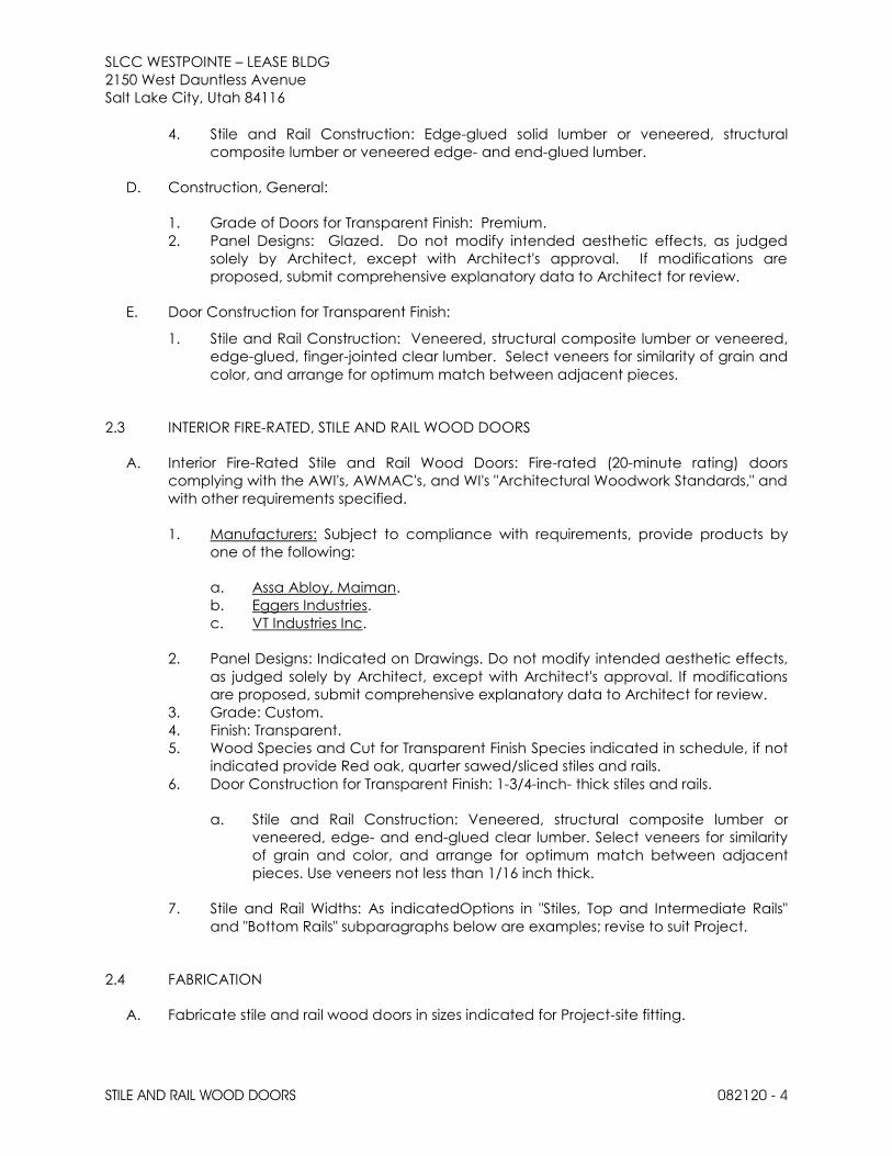
SLCC WESTPOINTE – LEASE BLDG 2150 West Dauntless Avenue
Salt Lake City, Utah 84116
STILE AND RAIL WOOD DOORS 082120 - 4
4. Stile and Rail Construction: Edge-glued solid lumber or veneered, structural
composite lumber or veneered edge- and end-glued lumber.
D. Construction, General:
1. Grade of Doors for Transparent Finish: Premium.
2. Panel Designs: Glazed. Do not modify intended aesthetic effects, as judged
solely by Architect, except with Architect's approval. If modifications are
proposed, submit comprehensive explanatory data to Architect for review.
E. Door Construction for Transparent Finish:
1. Stile and Rail Construction: Veneered, structural composite lumber or veneered,
edge-glued, finger-jointed clear lumber. Select veneers for similarity of grain and
color, and arrange for optimum match between adjacent pieces.
2.3 INTERIOR FIRE-RATED, STILE AND RAIL WOOD DOORS
A. Interior Fire-Rated Stile and Rail Wood Doors: Fire-rated (20-minute rating) doors
complying with the AWI's, AWMAC's, and WI's "Architectural Woodwork Standards," and
with other requirements specified.
1. Manufacturers: Subject to compliance with requirements, provide products by
one of the following:
a. Assa Abloy, Maiman.
b. Eggers Industries.
c. VT Industries Inc.
2. Panel Designs: Indicated on Drawings. Do not modify intended aesthetic effects,
as judged solely by Architect, except with Architect's approval. If modifications
are proposed, submit comprehensive explanatory data to Architect for review.
3. Grade: Custom.
4. Finish: Transparent.
5. Wood Species and Cut for Transparent Finish Species indicated in schedule, if not
indicated provide Red oak, quarter sawed/sliced stiles and rails.
6. Door Construction for Transparent Finish: 1-3/4-inch- thick stiles and rails.
a. Stile and Rail Construction: Veneered, structural composite lumber or
veneered, edge- and end-glued clear lumber. Select veneers for similarity
of grain and color, and arrange for optimum match between adjacent
pieces. Use veneers not less than 1/16 inch thick.
7. Stile and Rail Widths: As indicatedOptions in "Stiles, Top and Intermediate Rails"
and "Bottom Rails" subparagraphs below are examples; revise to suit Project.
2.4 FABRICATION
A. Fabricate stile and rail wood doors in sizes indicated for Project-site fitting.

SLCC WESTPOINTE – LEASE BLDG 2150 West Dauntless Avenue
Salt Lake City, Utah 84116
STILE AND RAIL WOOD DOORS 082120 - 5
B. Factory fit doors to suit frame-opening sizes indicated, with the following uniform
clearances and bevels, unless otherwise indicated:
1. Clearances: Provide 1/8 inch (3.2 mm) at heads, jambs, and between pairs of
doors. Provide 1/2 inch (13 mm) from bottom of door to top of decorative floor
finish or covering. Where threshold is shown or scheduled, provide 3/8 inch (10
mm) from bottom of door to top of threshold.
2. Comply with NFPA 80 for fire-rated doors.
3. Bevel non-fire-rated doors 1/8 inch in 2 inches at lock and hinge edges.
4. Bevel fire-rated doors 1/8 inch in 2 inches on lock edge; trim stiles and rails only to
extent permitted by labeling agency.
C. Factory machine doors for hardware that is not surface applied. Locate hardware to
comply with DHI-WDHS-3. Comply with final hardware schedules, door frame Shop
Drawings, DHI A115-W Series standards, and hardware templates.
1. Coordinate measurements of hardware mortises in metal frames to verify
dimensions and alignment before factory machining.
D. Glazed Openings: Glaze doors at factory with glass of type and thickness indicated,
complying with Division 8 Section "Glazing." Install glass using manufacturer's standard
elastomeric glazing sealant complying with ASTM C 920. Secure glass in place with
removable wood stops.
E. Glazed Openings: Trim openings indicated for glazing with solid wood moldings, with
one side removable.
F. Transom and Side Panels: Fabricate panels to match adjoining doors in materials, finish,
and quality of construction.
2.5 FACTORY FINISHING
A. General: Comply with referenced quality standard's requirements for factory finishing.
Finish faces and edges of doors, including mortises and cutouts.
B. Finish wood doors at factory. Match existing adjacent doors.
C. Transparent Finish: Comply with requirements indicated for grade, finish system, staining
effect, and sheen.
1. Grade: Premium.
2. Finish: Manufacturer's standard finish with performance requirements
comparable to AWI System TR-6 catalyzed polyurethane.
3. Staining: As selected by Architects .
4. Effect: Semifilled finish.
5. Sheen: Satin.

SLCC WESTPOINTE – LEASE BLDG 2150 West Dauntless Avenue
Salt Lake City, Utah 84116
STILE AND RAIL WOOD DOORS 082120 - 6
PART 3 - EXECUTION
3.1 EXAMINATION
A. Examine doors and substrates, with Installer present, for suitable conditions where wood
stile and rail doors will be installed.
1. Verify that installed frames comply with indicated requirements for type, size,
location, and swing characteristics and have been installed with plumb jambs
and level heads.
2. Reject doors with defects.
B. Proceed with installation only after unsatisfactory conditions have been corrected.
3.2 INSTALLATION
A. Install door frames level, plumb, true, and aligned with adjacent materials. Use
concealed shims where necessary for alignment.
1. Do not trim stiles and rails in excess of limits set by manufacturer or permitted with
fire-rated doors.
B. Hardware: For installation, see Division 08 Section "Door Hardware."
C. Install wood doors to comply with manufacturer's written instructions and with
referenced quality standard, and as indicated.
1. Install fire-rated doors according to NFPA 80.
D. Factory-Fitted Doors: Align in frames for uniform clearance at each edge.
E. Factory-Finished Doors: Restore finish before installation if fitting or machining is required
at Project site.
3.3 ADJUSTING AND PROTECTING
A. Operation: Rehang or replace doors that do not swing or operate freely.
B. Finished Doors: Replace doors that are damaged or do not comply with requirements.
Doors may be repaired or refinished if work complies with requirements and shows no
evidence of repair or refinishing.
END OF SECTION 08212

SLCC WESTPOINTE – LEASE BLDG 2150 West Dauntless Avenue
Salt Lake City, Utah 84116
ACCESS DOORS AND FRAMES 083113 - 1
SECTION 083113 - ACCESS DOORS AND FRAMES
PART 1 - GENERAL
1.1 RELATED DOCUMENTS
A. Drawings and general provisions of the Contract, including General and
Supplementary Conditions and Division 01 Specification Sections, apply to this Section.
1.2 SUMMARY
A. Section Includes:
1. Access doors and frames for walls and ceilings not provided by Divisions 22, 23 or
26.
1.3 ACTION SUBMITTALS
A. Product Data: For each type of product.
1. Include construction details, fire ratings, materials, individual components and
profiles, and finishes.
B. Shop Drawings:
1. Include plans, elevations, sections, details, and attachments to other work.
2. Detail fabrication and installation of access doors and frames for each type of
substrate.
C. Product Schedule: Provide complete access door and frame schedule, including
types, locations, sizes, latching or locking provisions, and other data pertinent to
installation.
PART 2 - PRODUCTS
2.1 PERFORMANCE REQUIREMENTS
A. Fire-Rated Access Doors and Frames: Units complying with NFPA 80 that are identical
to access door and frame assemblies tested for fire-test-response characteristics
according to the following test method and that are listed and labeled by UL or
another testing and inspecting agency acceptable to authorities having jurisdiction:
1. NFPA 252 or UL 10B for fire-rated access door assemblies installed vertically.
2. NFPA 288 for fire-rated access door assemblies installed horizontally.

SLCC WESTPOINTE – LEASE BLDG 2150 West Dauntless Avenue
Salt Lake City, Utah 84116
ACCESS DOORS AND FRAMES 083113 - 2
2.2 ACCESS DOORS AND FRAMES FOR WALLS AND CEILINGS
A. Manufacturers: Subject to compliance with requirements, provide products by one of
the following:
1. Access Panel Solutions.
2. Babcock-Davis.
3. J. L. Industries, Inc.; Div. of Activar Construction Products Group.
4. Karp Associates, Inc.
5. Larsen's Manufacturing Company.
6. Milcor Inc.
7. Approved equal.
B. Source Limitations: Obtain each type of access door and frame from single source
from single manufacturer.
C. Flush Access Doors with Concealed Flanges:
1. Assembly Description: Fabricate door to fit flush to frame. Provide frame with
gypsum board beads for concealed flange installation.
2. Locations: Wall and ceiling.
3. Door Size: Minimum 16” x 20” or size as indicated on drawings.
4. Uncoated Steel Sheet for Door: Nominal 0.060 inch (1.52 mm), 16 gage.
a. Finish: Factory finish.
5. Metallic-Coated Steel Sheet for Door, for wet locations: Nominal 0.064 inch (1.63
mm), 16 gauge.
a. Finish: Factory finish.
D. Fire-Rated, Flush Access Doors with Concealed Flanges:
1. Assembly Description: Fabricate door to fit flush to frame, with a core of mineral-
fiber insulation enclosed in sheet metal. Provide self-latching door with automatic
closer and interior latch release. Provide frame with gypsum board beads for
concealed flange installation.
2. Locations: Wall and ceiling.
3. Fire-Resistance Rating: Not less than that of adjacent construction.
4. Temperature-Rise Rating: 250 deg F (139 deg C) at the end of 30 minutes.
5. Uncoated Steel Sheet for Door: Nominal 0.036 inch (0.91 mm), 20 gage.
a. Finish: Factory finish.
6. Metallic-Coated Steel Sheet for Door, at wet locations: Nominal 0.040 inch, 20
gauge.
a. Finish: Factory finish.
7. Frame Material: Same material, thickness, and finish as door.
8. Hinges: Manufacturer's standard.

SLCC WESTPOINTE – LEASE BLDG 2150 West Dauntless Avenue
Salt Lake City, Utah 84116
ACCESS DOORS AND FRAMES 083113 - 3
E. Hardware:
1. Latch: Cam latch operated by screwdriver at non-public spaces or areas.
2. Lock: Cylinder in all public spaces or areas.
a. Lock Preparation: Prepare door panel to accept cylinder specified in
Section 087100 "Door Hardware."
2.3 MATERIALS
A. Steel Plates, Shapes, and Bars: ASTM A 36/A 36M.
B. Steel Sheet: Uncoated or electrolytic zinc coated, ASTM A 879/A 879M, with cold-rolled
steel sheet substrate complying with ASTM A 1008/A 1008M, Commercial Steel (CS),
exposed.
C. Metallic-Coated Steel Sheet: ASTM A 653/A 653M, Commercial Steel (CS), Type B; with
minimum G60 (Z180) or A60 (ZF180) metallic coating.
D. Frame Anchors: Same type as door face.
E. Inserts, Bolts, and Anchor Fasteners: Hot-dip galvanized steel according to
ASTM A 153/A 153M or ASTM F 2329.
2.4 FABRICATION
A. General: Provide access door and frame assemblies manufactured as integral units
ready for installation.
B. Metal Surfaces: For metal surfaces exposed to view in the completed Work, provide
materials with smooth, flat surfaces without blemishes. Do not use materials with
exposed pitting, seam marks, roller marks, rolled trade names, or roughness.
C. Doors and Frames: Grind exposed welds smooth and flush with adjacent surfaces.
Furnish attachment devices and fasteners of type required to secure access doors to
types of supports indicated.
1. For concealed flanges with drywall bead, provide edge trim for gypsum board
securely attached to perimeter of frames.
2. Provide mounting holes in frames for attachment of units to metal or wood
framing.
3. Provide mounting holes in frame for attachment of masonry anchors.
D. Latching Mechanisms: Furnish number required to hold doors in flush, smooth plane
when closed.
1. For cylinder locks, furnish two keys per lock and key all locks alike.
2. For recessed panel doors, provide access sleeves for each locking device.
Furnish plastic grommets and install in holes cut through finish.

SLCC WESTPOINTE – LEASE BLDG 2150 West Dauntless Avenue
Salt Lake City, Utah 84116
ACCESS DOORS AND FRAMES 083113 - 4
E. Extruded Aluminum: After fabrication, apply manufacturer's standard protective
coating on aluminum that will come in contact with concrete.
2.5 FINISHES
A. Comply with NAAMM's "Metal Finishes Manual for Architectural and Metal Products" for
recommendations for applying and designating finishes.
B. Protect mechanical finishes on exposed surfaces from damage by applying a
strippable, temporary protective covering before shipping.
C. Appearance of Finished Work: Noticeable variations in same piece are not
acceptable. Variations in appearance of adjoining components are acceptable if
they are within the range of approved Samples and are assembled or installed to
minimize contrast.
D. Steel and Metallic-Coated-Steel Finishes:
1. Factory Finish: Immediately after cleaning and pretreating, apply manufacturer's
standard two-coat, baked-on finish consisting of prime coat and thermosetting
topcoat, with a minimum dry-film thickness of 1 mil (0.025 mm) for topcoat.
PART 3 - EXECUTION
3.1 EXAMINATION
A. Examine substrates for compliance with requirements for installation tolerances and
other conditions affecting performance of the Work.
B. Proceed with installation only after unsatisfactory conditions have been corrected.
3.2 INSTALLATION
A. Comply with manufacturer's written instructions for installing access doors and frames.
B. Install doors flush with adjacent finish surfaces or recessed to receive finish material.
3.3 ADJUSTING
A. Adjust doors and hardware, after installation, for proper operation.
B. Remove and replace doors and frames that are warped, bowed, or otherwise
damaged.
END OF SECTION 083113

SLCC WESTPOINTE – LEASE BLDG 2150 West Dauntless Avenue
Salt Lake City, Utah 84116
COILING COUNTER DOORS 083313 - 1
SECTION 083313 - COILING COUNTER DOORS
PART 1 - GENERAL
1.1 RELATED DOCUMENTS
A. Drawings and general provisions of the Contract, including General and
Supplementary Conditions and Division 01 Specification Sections, apply to this Section.
1.2 SUMMARY
A. Section Includes:
1. Fire-rated manually operated counter doors with integrated frame and counter
panel.
B. Related Requirements:
1. Section 055000 "Metal Fabrications".
1.3 ACTION SUBMITTALS
A. Product Data: For each type and size of coiling counter door and accessory.
1. Include construction details, material descriptions, dimensions of individual
components, profiles for slats, and finishes.
2. Include rated capacities, operating characteristics, electrical characteristics, and
furnished accessories.
3. Include description of automatic closing device and testing and resetting
instructions.
B. Shop Drawings: For each installation and for special components not dimensioned or
detailed in manufacturer's product data.
1. Include plans, elevations, sections, and mounting details.
2. Include details of equipment assemblies, and indicate dimensions, required
clearances, method of field assembly, components, and location and size of
each field connection.
3. Include points of attachment and their corresponding static and dynamic loads
imposed on structure.
4. Show locations of controls, locking devices, detectors or replaceable fusible links,
and other accessories.
5. Include diagrams for power, signal, and control wiring.
C. Samples for Initial Selection: Manufacturer's finish charts showing full range of colors and
textures available for units with factory-applied finishes.

SLCC WESTPOINTE – LEASE BLDG 2150 West Dauntless Avenue
Salt Lake City, Utah 84116
COILING COUNTER DOORS 083313 - 2
1. Include similar Samples of accessories involving color selection.
D. Samples for Verification: For each type of exposed finish on the following components,
in manufacturer's standard sizes:
1. Curtain slats.
2. Bottom bar.
3. Guides.
4. Brackets.
5. Hood.
6. Laminate-clad counter panel product for each type, color, pattern, and surface
finish; laminated to core.
7. Locking device(s).
8. Include similar Samples of accessories involving color selection.
1.4 INFORMATIONAL SUBMITTALS
A. Qualification Data: For Installer.
B. Oversize Construction Certification: For door assemblies required to be fire-rated and
that exceed size limitations of labeled assemblies.
1.5 CLOSEOUT SUBMITTALS
A. Maintenance Data: For coiling counter doors to include in maintenance manuals.
1.6 QUALITY ASSURANCE
A. Installer Qualifications: An entity that employs installers and supervisors who are trained
and approved by manufacturer for both installation and maintenance of units required
for this Project.
1. Maintenance Proximity: Not more than two hours' normal travel time from
Installer's place of business to Project site.
B. Fire-Rated Door Assemblies: Complying with NFPA 80; listed and labeled by a qualified
testing agency, for fire-protection ratings indicated, based on testing at as close to
neutral pressure as possible according to NFPA 252 or UL 10B.
1. Smoke Control: In corridors and smoke barriers, provide doors that are listed and
labeled with the letter "S" on the fire-rating label by a qualified testing agency for
smoke- and draft-control based on testing according to UL 1784; with maximum
air-leakage rate of 3.0 cfm/sq. ft. of door opening at 0.10-inch wg for both
ambient and elevated temperature tests.
C. Sound-Control Doors: Assemblies tested in a laboratory for sound-transmission-loss
performance according to ASTM E 90, calculated according to ASTM E 413, and rated
for not less than the STC value indicated.

SLCC WESTPOINTE – LEASE BLDG 2150 West Dauntless Avenue
Salt Lake City, Utah 84116
COILING COUNTER DOORS 083313 - 3
PART 2 - PRODUCTS
2.1 MANUFACTURERS
A. Source Limitations: Obtain coiling counter doors from single source from single
manufacturer.
1. Obtain operators and controls from coiling counter door manufacturer.
2.2 FIRE-RATED COUNTER DOOR ASSEMBLY
A. Fire-Rated Counter Door: Overhead fire-rated coiling door formed with curtain of
interlocking metal slats.
1. Manufacturers: Subject to compliance with requirements, provide products by
one of the following:
a. Cookson Company.
b. Cornell Iron Works, Inc.
c. Overhead Door Corporation.
d. Wayne-Dalton Corp.
B. Operation Cycles: Door components and operators capable of operating for not less
than 100,000. One operation cycle is complete when a door is opened from the closed
position to the fully open position and returned to the closed position.
1. Include tamperproof cycle counter.
C. Fire Rating: 1/3 hour (20 minute) with temperature-rise limit and with smoke control.
D. STC Rating: 27.
E. Door Curtain Material: Stainless steel.
F. Door Curtain Slats: interlocked Flat profile slats of 1-1/2-inch center-to-center height.
G. Curtain Jamb Guides: Stainless steel with exposed finish matching curtain slats.
H. Hood: Match curtain material and finish.
1. Shape: Square.
2. Mounting: Face of Stud Wall.
I. Integral Frame, Hood, and Fascia: Stainless steel.
1. Mounting: Face of Stud Wall.
J. Sill Configuration: Fire-rated, laminate counter.
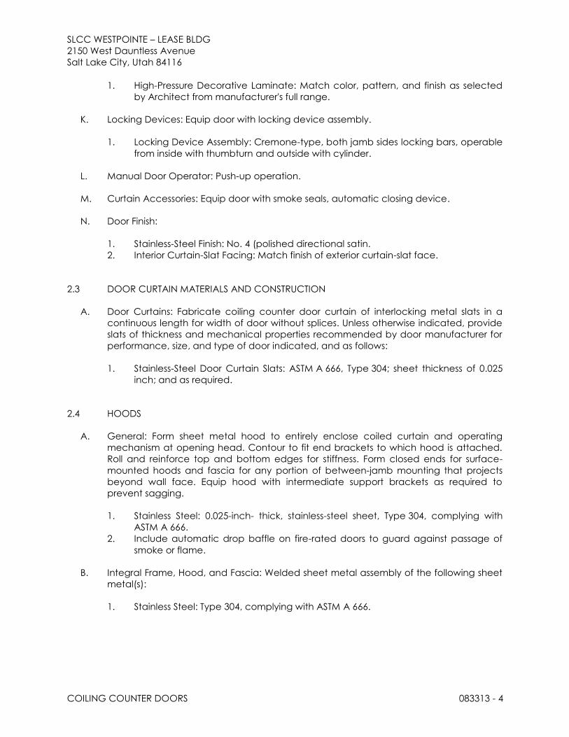
SLCC WESTPOINTE – LEASE BLDG 2150 West Dauntless Avenue
Salt Lake City, Utah 84116
COILING COUNTER DOORS 083313 - 4
1. High-Pressure Decorative Laminate: Match color, pattern, and finish as selected
by Architect from manufacturer's full range.
K. Locking Devices: Equip door with locking device assembly.
1. Locking Device Assembly: Cremone-type, both jamb sides locking bars, operable
from inside with thumbturn and outside with cylinder.
L. Manual Door Operator: Push-up operation.
M. Curtain Accessories: Equip door with smoke seals, automatic closing device.
N. Door Finish:
1. Stainless-Steel Finish: No. 4 (polished directional satin.
2. Interior Curtain-Slat Facing: Match finish of exterior curtain-slat face.
2.3 DOOR CURTAIN MATERIALS AND CONSTRUCTION
A. Door Curtains: Fabricate coiling counter door curtain of interlocking metal slats in a
continuous length for width of door without splices. Unless otherwise indicated, provide
slats of thickness and mechanical properties recommended by door manufacturer for
performance, size, and type of door indicated, and as follows:
1. Stainless-Steel Door Curtain Slats: ASTM A 666, Type 304; sheet thickness of 0.025
inch; and as required.
2.4 HOODS
A. General: Form sheet metal hood to entirely enclose coiled curtain and operating
mechanism at opening head. Contour to fit end brackets to which hood is attached.
Roll and reinforce top and bottom edges for stiffness. Form closed ends for surface-
mounted hoods and fascia for any portion of between-jamb mounting that projects
beyond wall face. Equip hood with intermediate support brackets as required to
prevent sagging.
1. Stainless Steel: 0.025-inch- thick, stainless-steel sheet, Type 304, complying with
ASTM A 666.
2. Include automatic drop baffle on fire-rated doors to guard against passage of
smoke or flame.
B. Integral Frame, Hood, and Fascia: Welded sheet metal assembly of the following sheet
metal(s):
1. Stainless Steel: Type 304, complying with ASTM A 666.

SLCC WESTPOINTE – LEASE BLDG 2150 West Dauntless Avenue
Salt Lake City, Utah 84116
COILING COUNTER DOORS 083313 - 5
2.5 LOCKING DEVICES
A. Slide Bolt: Fabricate with side-locking bolts to engage through slots in tracks for locking
by padlock, located on both left and right jamb sides, operable from coil side.
B. Locking Device Assembly: Fabricate with cylinder lock, spring-loaded dead bolt,
operating handle, cam plate, and adjustable locking bars to engage through slots in
tracks.
1. Lock Cylinders: As specified in Section 087100 "Door Hardware and keyed to
building keying system.
2. Keys: Three for each cylinder.
2.6 CURTAIN ACCESSORIES
A. Smoke Seals: Equip each fire-rated door with replaceable smoke-seal perimeter
gaskets or brushes for smoke and draft control as required for door listing and labeling
by a qualified testing agency.
B. Pull-Down Strap: Provide pull-down straps for doors more than 84 inches (2130 mm)
high.
2.7 COUNTER DOOR ACCESSORIES
A. Fire-Rated, Laminate Counter: Fire-door manufacturer's high-pressure, decorative
laminate-covered countertop; UL or ITS tested and labeled for 1-1/2-hour fire rating for
approved use with fire-door assembly.
2.8 COUNTERBALANCE MECHANISM
A. Counterbalance Spring: One or more oil-tempered, heat-treated steel helical torsion
springs. Size springs to counterbalance weight of curtain, with uniform adjustment
accessible from outside barrel. Secure ends of springs to barrel and shaft with cast-steel
barrel plugs.
1. Fire-Rated Doors: Equip with auxiliary counterbalance spring and prevent tension
release from main counterbalance spring when automatic closing device
operates.
2.9 MANUAL DOOR OPERATORS
A. General: Equip door with manual door operator by door manufacturer.
B. Push-up Door Operation: Design counterbalance mechanism so that required lift or pull
for door operation does not exceed 25 lbf.

SLCC WESTPOINTE – LEASE BLDG 2150 West Dauntless Avenue
Salt Lake City, Utah 84116
COILING COUNTER DOORS 083313 - 6
2.10 GENERAL FINISH REQUIREMENTS
A. Comply with NAAMM/NOMMA 500 for recommendations for applying and designating
finishes.
B. Appearance of Finished Work: Noticeable variations in same piece are not
acceptable. Variations in appearance of adjoining components are acceptable if
they are within the range of approved Samples and are assembled or installed to
minimize contrast.
2.11 STAINLESS-STEEL FINISHES
A. Surface Preparation: Remove tool and die marks and stretch lines, or blend into finish.
B. Polished Finishes: Grind and polish surfaces to produce uniform finish, free of cross
scratches.
1. Run grain of directional finishes with long dimension of each piece.
2. When polishing is completed, passivate and rinse surfaces. Remove embedded
foreign matter and leave surfaces chemically clean.
3. Directional Satin Finish: No. 4.
PART 3 - EXECUTION
3.1 EXAMINATION
A. Examine substrates areas and conditions, with Installer present, for compliance with
requirements for substrate construction and other conditions affecting performance of
the Work.
B. Proceed with installation only after unsatisfactory conditions have been corrected.
3.2 INSTALLATION
A. Install coiling counter doors and operating equipment complete with necessary
hardware, anchors, inserts, hangers, and equipment supports; according to
manufacturer's written instructions and as specified.
B. Install coiling counter doors, hoods, controls, and operators at the mounting locations
indicated for each door.
C. Fire-Rated Doors: Install according to NFPA 80.
D. Smoke-Control Doors: Install according to NFPA 80 and NFPA 105.

SLCC WESTPOINTE – LEASE BLDG 2150 West Dauntless Avenue
Salt Lake City, Utah 84116
COILING COUNTER DOORS 083313 - 7
3.3 ADJUSTING
A. Adjust hardware and moving parts to function smoothly so that doors operate easily,
free of warp, twist, or distortion.
B. Lubricate bearings and sliding parts as recommended by manufacturer.
C. Adjust seals to provide tight fit around entire perimeter.
3.4 MAINTENANCE SERVICE
A. Initial Maintenance Service: Beginning at Substantial Completion, maintenance service
shall include nine months' full maintenance by skilled employees of coiling-door
Installer. Include monthly preventive maintenance, repair or replacement of worn or
defective components, lubrication, cleaning, and adjusting as required for proper door
operation. Parts and supplies shall be manufacturer's authorized replacement parts and
supplies.
1. Perform maintenance, including emergency callback service, during normal
working hours.
2. Include 24-hour-per-day, seven-day-per-week, emergency callback service.
3.5 DEMONSTRATION
A. Engage a factory-authorized service representative to train Owner's maintenance
personnel to adjust, operate, and maintain coiling counter doors.
END OF SECTION 083313

SLCC WESTPOINTE – LEASE BLDG 2150 West Dauntless Avenue
Salt Lake City, Utah 84116
COILING COUNTER DOORS 083313 - 8
THIS PAGE IS INTENTIONALLY LEFT BLANK

SLCC WESTPOINTE – LEASE BLDG 2150 West Dauntless Avenue
Salt Lake City, Utah 84116
ALUMINUM-FRAMED ENTRANCES AND STOREFRONTS (INTERIOR) 084115 - 1
SECTION 084115 - ALUMINUM-FRAMED ENTRANCES AND STOREFRONTS (INTERIOR)
PART 1 - GENERAL
1.1 Related Documents
A. Drawings and general provisions of the Contract, including General and Supplementary
Conditions and Division 01 Specification Sections, apply to this Section.
1.2 Summary
A. Section Includes: Interior storefront using Kawneer Architectural Aluminum Storefront Systems,
including perimeter trims, stools, accessories, shims and anchors, and perimeter sealing of
storefront units.
1. Types of Kawneer Aluminum Storefront Systems include:
a. Trifab™ VG 450 Framing System – 1-3/4" x 4-1/2" nominal dimension; Non-Thermal;
Center, , Screw Spline Fabrication.
B. Related Sections:
1. 079200 “Joint Sealants”
2. 081416 “Flush Wood Doors”.
3. 088000 “Glazing”
1.3 Definitions
A. Definitions: For fenestration industry standard terminology and definitions refer to American
Architectural Manufacturers Association (AAMA) – AAMA Glossary (AAMA AG).
1.4 Performance Requirements
A. Storefront System Performance Requirements:
1. Uniform Load: A static air design load of 10 psf shall be applied in the positive and negative
direction in accordance with ASTM E 330. There shall be no deflection in excess of L/175 of
the span of any framing member. At a structural test load equal to 1.5 times the specified
design load, no glass breakage or permanent set in the framing members in excess of 0.2%
of their clear spans shall occur.
B. Delegated Design: Design glazed alumiumn curtain walls, indlcing comprehensive
engineering analysis by a qualitided professional engineer licensed in the state of Utah, using
performance requiments and design criteria for the project locations.
1.5 Submittals
A. Product Data: Include construction details, material descriptions, dimensions of individual
components and profiles, hardware, finishes, and installation instructions for each type of
aluminum-framed storefront system indicated.
B. Shop Drawings: Include plans, elevations, sections, details, hardware, and attachments to other
work, operational clearances and installation details.
C. Samples for Verification: For aluminum-framed storefront system and components required.
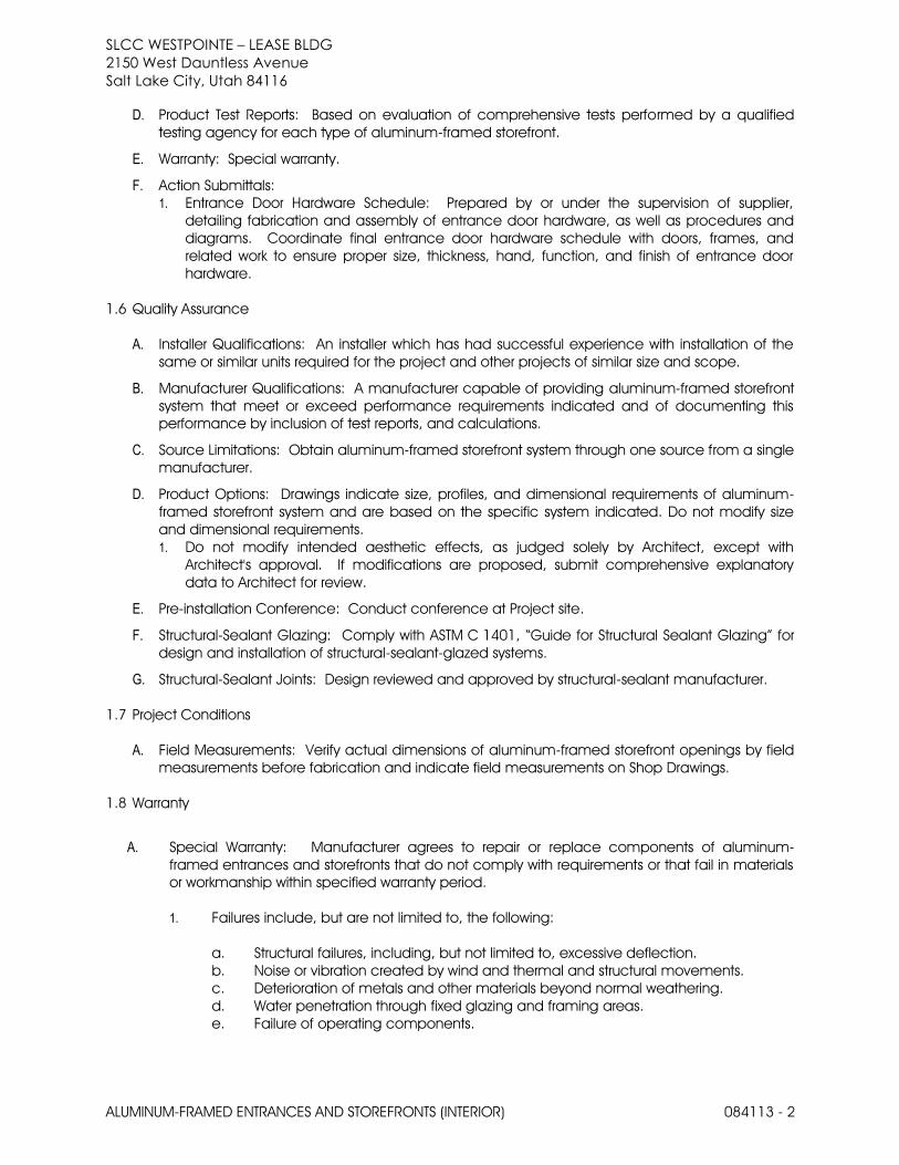
SLCC WESTPOINTE – LEASE BLDG 2150 West Dauntless Avenue
Salt Lake City, Utah 84116
ALUMINUM-FRAMED ENTRANCES AND STOREFRONTS (INTERIOR) 084113 - 2
D. Product Test Reports: Based on evaluation of comprehensive tests performed by a qualified
testing agency for each type of aluminum-framed storefront.
E. Warranty: Special warranty.
F. Action Submittals:
1. Entrance Door Hardware Schedule: Prepared by or under the supervision of supplier,
detailing fabrication and assembly of entrance door hardware, as well as procedures and
diagrams. Coordinate final entrance door hardware schedule with doors, frames, and
related work to ensure proper size, thickness, hand, function, and finish of entrance door
hardware.
1.6 Quality Assurance
A. Installer Qualifications: An installer which has had successful experience with installation of the
same or similar units required for the project and other projects of similar size and scope.
B. Manufacturer Qualifications: A manufacturer capable of providing aluminum-framed storefront
system that meet or exceed performance requirements indicated and of documenting this
performance by inclusion of test reports, and calculations.
C. Source Limitations: Obtain aluminum-framed storefront system through one source from a single
manufacturer.
D. Product Options: Drawings indicate size, profiles, and dimensional requirements of aluminum-
framed storefront system and are based on the specific system indicated. Do not modify size
and dimensional requirements.
1. Do not modify intended aesthetic effects, as judged solely by Architect, except with
Architect's approval. If modifications are proposed, submit comprehensive explanatory
data to Architect for review.
E. Pre-installation Conference: Conduct conference at Project site.
F. Structural-Sealant Glazing: Comply with ASTM C 1401, “Guide for Structural Sealant Glazing” for
design and installation of structural-sealant-glazed systems.
G. Structural-Sealant Joints: Design reviewed and approved by structural-sealant manufacturer.
1.7 Project Conditions
A. Field Measurements: Verify actual dimensions of aluminum-framed storefront openings by field
measurements before fabrication and indicate field measurements on Shop Drawings.
1.8 Warranty
A. Special Warranty: Manufacturer agrees to repair or replace components of aluminum-
framed entrances and storefronts that do not comply with requirements or that fail in materials
or workmanship within specified warranty period.
1. Failures include, but are not limited to, the following:
a. Structural failures, including, but not limited to, excessive deflection.
b. Noise or vibration created by wind and thermal and structural movements.
c. Deterioration of metals and other materials beyond normal weathering.
d. Water penetration through fixed glazing and framing areas.
e. Failure of operating components.

SLCC WESTPOINTE – LEASE BLDG 2150 West Dauntless Avenue
Salt Lake City, Utah 84116
ALUMINUM-FRAMED ENTRANCES AND STOREFRONTS (INTERIOR) 084115 - 3
2. Warranty Period: Five years from date of Substantial Completion.
B. Special Finish Warranty: Standard form in which manufacturer agrees to repair finishes or
replace aluminum that shows evidence of deterioration of factory-applied finishes within
specified warranty period.
1. Deterioration includes, but is not limited to, the following:
a. Color fading more than 5 Hunter units when tested according to ASTM D 2244.
b. Chalking in excess of a No. 8 rating when tested according to ASTM D 4214.
c. Cracking, checking, peeling, or failure of paint to adhere to bare metal.
2. Warranty Period: Five years from date of Substantial Completion.
PART 2 - PRODUCTS
2.1 Manufacturers
A. Basis-of-Design Product:
1. Kawneer Company Inc.
2. Trifab™ VG 450 Framing System (Non-Thermal)
3. System Dimensions: 1-3/4" x 4-1/2"
4. Glass: Front; butt glazed.
2.2 Materials
A. Aluminum Extrusions: Alloy and temper recommended by aluminum storefront manufacturer for
strength, corrosion resistance, and application of required finish and not less than 0.070" (1.8
mm) wall thickness at any location for the main frame and complying with ASTM B 221: 6063-T6
alloy and temper.
B. Fasteners: Aluminum, nonmagnetic stainless steel or other materials to be non-corrosive and
compatible with aluminum framing members, trim hardware, anchors, and other components.
C. Anchors, Clips, and Accessories: Aluminum, nonmagnetic stainless steel, or zinc-coated steel or
iron complying with ASTM B 633 for SC 3 severe service conditions or other suitable zinc coating;
provide sufficient strength to withstand design pressure indicated.
D. Reinforcing Members: Aluminum, nonmagnetic stainless steel, or nickel/chrome-plated steel
complying with ASTM B 456 for Type SC 3 severe service conditions, or zinc-coated steel or iron
complying with ASTM B 633 for SC 3 severe service conditions or other suitable zinc coating;
provide sufficient strength to withstand design pressure indicated.
E. Sealant: For sealants required within fabricated storefront system, provide permanently elastic,
non-shrinking, and non-migrating type recommended by sealant manufacturer for joint size and
movement.
F. Tolerances: Reference to tolerances for wall thickness and other cross-sectional dimensions of
storefront members are nominal and in compliance with AA Aluminum Standards and Data.
2.3 Storefront Framing System
A. Brackets and Reinforcements: Manufacturer's standard high-strength aluminum with
nonstaining, nonferrous shims for aligning system components.

SLCC WESTPOINTE – LEASE BLDG 2150 West Dauntless Avenue
Salt Lake City, Utah 84116
ALUMINUM-FRAMED ENTRANCES AND STOREFRONTS (INTERIOR) 084113 - 4
B. Fasteners and Accessories: Manufacturer's standard corrosion-resistant, nonstaining,
nonbleeding fasteners and accessories compatible with adjacent materials. Where exposes
shall be stainless steel.
C. Perimeter Anchors: When steel anchors are used, provide insulation between steel material and
aluminum material to prevent galvanic action
D. Packing, Shipping, Handling and Unloading: Deliver materials in manufacturer's original,
unopened, undamaged containers with identification labels intact.
E. Storage and Protection: Store materials protected from exposure to harmful weather conditions.
Handle storefront material and components to avoid damage. Protect storefront material
against damage from elements, construction activities, and other hazards before, during and
after storefront installation.
2.4 Glazing Systems; butt glazed.
A. Glazing: As specified in Division 08 Section “Glazing”.
B. Glazing Gaskets: Manufacturer's standard sealed-corner pressure-glazing system of black,
resilient elastomeric glazing gaskets, setting blocks, and shims or spacers.
C. Glazing Sealants: As recommended by manufacturer.
D. Structural Glazing Sealants: ASTM C 1184 chemically curing silicone formulation that is
compatible with system components with which it comes in contact; specifically formulated
and tested for use as structural sealant and approved by structural-sealant manufacturer for
use in storefront system indicated.
1. Color: As selected by Architect from manufacturer's full range of colors.
E. Weatherseal Sealants: ASTM C 920 for Type S; Grade NS; Class 25; Uses NT, G, A, and O;
chemically curing silicone formulation that is compatible with structural sealant and other
system components with which it comes in contact; recommended by structural-sealant,
weatherseal-sealant, and structural-sealant-glazed storefront manufacturers for this use.
1. Color: Match structural sealant.
2.5 Entrance Door Systems
A. Entrance Doors: Flush wood doors as specified in specification section 081416 “Flush Wood
Doors”.
1. Glazing Stops and Gaskets: Square, snap-on, extruded-aluminum stops and preformed
gaskets.
B. Provide nonremovable glazing stops on outside of door.
C. General: Provide entrance door hardware and entrance door hardware sets indicated in door
and frame schedule for each entrance door, to comply with requirements in this Section.
D. Designations: Requirements for design, grade, function, finish, quantity, size, and other
distinctive qualities of each type of entrance door hardware are indicated in "Entrance Door
Hardware Sets" Article. Products are identified by using entrance door hardware designations
as follows:

SLCC WESTPOINTE – LEASE BLDG 2150 West Dauntless Avenue
Salt Lake City, Utah 84116
ALUMINUM-FRAMED ENTRANCES AND STOREFRONTS (INTERIOR) 084115 - 5
1. Named Manufacturers' Products: Manufacturer and product designation are listed for
each door hardware type required for the purpose of establishing minimum
requirements. Manufacturers' names are abbreviated in "Entrance Door Hardware Sets"
Article.
2. References to BHMA Standards: Provide products complying with these standards and
requirements for description, quality, and function.
E. Cylinders: As specified in Section 087100 "Door Hardware."
2.6 Accessory Materials
A. Joint Sealants: For installation at perimeter of aluminum-framed systems, as specified in
Division 07 Section “Joint Sealants”.
B. Bituminous Paint: Cold-applied, asphalt-mastic paint complying with SSPC-Paint 12
requirements except containing no asbestos; formulated for 30 mil (0.762 mm) thickness per
coat.
2.7 Fabrication
A. Framing Members, General: Fabricate components that, when assembled, have the following
characteristics:
1. Profiles that are sharp, straight, and free of defects or deformations.
2. Accurately fit joints; make joints flush, hairline and weatherproof.
3. Means to drain water passing joints, condensation within framing members, and moisture
migrating within the system to exterior.
4. Physical and thermal isolation of glazing from framing members.
5. Accommodations for thermal and mechanical movements of glazing and framing to
maintain required glazing edge clearances.
6. Provisions for field replacement of glazing.
7. Fasteners, anchors, and connection devices that are concealed from view to greatest
extent possible.
B. Mechanically Glazed Framing Members: Fabricate for flush glazing without projecting stops.
C. Structural-Sealant-Glazed Framing Members: Include accommodations for using temporary
support device to retain glazing in place while structural sealant cures.
D. Storefront Framing: Fabricate components for assembly using manufacturer’s standard
installation instructions.
E. After fabrication, clearly mark components to identify their locations in Project according to
Shop Drawings.
2.8 Aluminum Finishes
A. Finish designations prefixed by AA comply with the system established by the Aluminum
Association for designating aluminum finishes.
B. Factory Finishing:
1. Kawneer Permanodic™ AA-M10C21A44 / AA-M45C22A44, AAMA 611, Architectural Class I
Color Anodic Coating (Color Black, unless otherwise indicated).

SLCC WESTPOINTE – LEASE BLDG 2150 West Dauntless Avenue
Salt Lake City, Utah 84116
ALUMINUM-FRAMED ENTRANCES AND STOREFRONTS (INTERIOR) 084113 - 6
PART 3 - EXECUTION
3.1 Examination
A. Examine openings, substrates, structural support, anchorage, and conditions, with Installer
present, for compliance with requirements for installation tolerances and other conditions
affecting performance of work. Verify rough opening dimensions, levelness of sill plate and
operational clearances. Examine wall flashings, vapor retarders, water and weather barriers,
and other built-in components to ensure a coordinated, weather tight aluminum- framed
storefront system installation.
1. Metal Frame Walls: Dry; clean; free of grease, oil, dirt, rust, corrosion, and welding slag;
without sharp edges or offsets at joints.
2. Proceed with installation only after unsatisfactory conditions have been corrected.
3.2 Installation
A. Comply with Drawings, Shop Drawings, and manufacturer's written instructions for installing
aluminum-framed storefront system, accessories, and other components.
B. Install aluminum-framed storefront system level, plumb, square, true to line, without distortion or
impeding thermal movement, anchored securely in place to structural support, and in proper
relation to wall flashing and other adjacent construction.
C. Set sill members in bed of sealant or with gaskets, as indicated, for weather tight construction.
D. Install aluminum framed storefront system and components to drain condensation, water
penetrating joints, and moisture migrating within aluminum-framed storefront system to the
exterior.
E. Separate aluminum and other corrodible surfaces from sources of corrosion or electrolytic
action at points of contact with other materials.
3.3 Field Quality Control
A. Field Tests: Architect shall select storefront units to be tested as soon as a representative portion
of the project has been installed, glazed, perimeter caulked and cured. Conduct tests for air
infiltration and water penetration with manufacturer's representative present. Tests not meeting
specified performance requirements and units having deficiencies shall be corrected as part of
the contract amount.
1. Testing: Testing shall be performed by a qualified independent testing agency. Refer to
Testing Section for payment of testing and testing requirements. Testing Standard per AAMA
503, including reference to ASTM E 783 for Air Infiltration Test and ASTM E 1105 Water
Infiltration Test.
a. Air Infiltration Tests: Conduct tests in accordance with ASTM E 783. Allowable air infiltration
shall not exceed 1.5 times the amount indicated in the performance requirements or
0.09 cfm/ft2, whichever is greater.
b. Water Infiltration Tests: Conduct tests in accordance with ASTM E 1105. No uncontrolled
water leakage is permitted when tested at a static test pressure of two-thirds the
specified water penetration pressure but not less than 6.24 psf (300 Pa).
B. Manufacturer's Field Services: Upon Owner’s written request, provide periodic site visit by
manufacturer’s field service representative.

SLCC WESTPOINTE – LEASE BLDG 2150 West Dauntless Avenue
Salt Lake City, Utah 84116
ALUMINUM-FRAMED ENTRANCES AND STOREFRONTS (INTERIOR) 084115 - 7
3.4 Adjusting, Cleaning, and Protection
A. Clean aluminum surfaces immediately after installing aluminum-framed storefronts. Avoid
damaging protective coatings and finishes. Remove excess sealants, glazing materials, dirt,
and other substances.
B. Clean glass immediately after installation. Comply with glass manufacturer's written
recommendations for final cleaning and maintenance. Remove nonpermanent labels, and
clean surfaces.
C. Remove and replace glass that has been broken, chipped, cracked, abraded, or damaged
during construction period.
END OF SECTION 084113

SLCC WESTPOINTE – LEASE BLDG 2150 West Dauntless Avenue
Salt Lake City, Utah 84116
ALUMINUM-FRAMED ENTRANCES AND STOREFRONTS (INTERIOR) 084113 - 8
THIS PAGE IS INTENTIONALLY LEFT BLANK

SLCC WESTPOINTE – LEASE BLDG 2150 West Dauntless Avenue
Salt Lake City, Utah 84116
DOOR HARDWARE 087100 - 1
SECTION 087100 - DOOR HARDWARE
PART 1 - GENERAL
1.1 RELATED DOCUMENTS
A. Drawings and general provisions of the Contract, including General and Supplemental
Conditions and Division 01 Specification Sections, apply to this Section.
1.2 SUMMARY
A. Section Includes:
1. Door hardware for swinging doors and other doors to the extent indicated.
2. Field verification, preparation, and modification of existing doors and frames to
receive new door hardware
3. Cylinders and hardware for special doors as scheduled in hardware sets.
4. Electro-mechanical devices and access control components as specified herein.
B. Related Sections
1. Section 08 1113: “Hollow Metal Doors and Frames”
2. Section 08 1400: “Wood Doors”
1.3 REFERENCED STANDARDS
A. American National Standards Institute (ANSI):
1. International Code Council (ICC): ANSI/ICC A117.1: Accessible and Usable
Buildings and Facilities, edition as adopted by local Authority Having Jurisdiction
(AHJ).
2. Builders Hardware Manufacturer’s Association (BHMA)
a. ANSI/BHMA A156.1; Butts & Hinges; 2013 edition
b. ANSI/BHMA A156.2; Bored and Preassembled Locks and Latches; 2011
edition
c. ANSI/BHMA A156.3; Exit Devices; 2014 edition
d. ANSI/BHMA A156.4; Door Controls - Closers; 2013 edition
e. ANSI/BHMA A156.8; Door Controls - Overhead Stops and Holders; 2010
edition
f. ANSI/BHMA A156.6; Architectural Door Trim; 2010 edition
g. ANSI/BHMA A156.8; Door Controls - Overhead Stops and Holders; 2010
edition
h. ANSI/BHMA A156.18; Materials and Finishes; 2012 edition
i. ANSI/BHMA A156.26; Continuous Hinges; 2012 edition
B. Door and Hardware Institute (DHI)
1. Keying Systems and Nomenclature, 2003 edition
2. Sequence and Format for the Hardware Schedule, 2001 edition

SLCC WESTPOINTE – LEASE BLDG 2150 West Dauntless Avenue
Salt Lake City, Utah 84116
DOOR HARDWARE 087100 - 2
C. National Fire Protection Association (NFPA)
1. NFPA 80: Standard for Fire Doors and Other Opening Protectives, edition as
adopted by local AHJ.
2. NFPA 105: Standard for the Installation of Smoke Door Assemblies and Other
Opening Protectives, edition as adopted by local AHJ.
3. NFPA 252: Standard Methods of Fire Tests of Door Assemblies, edition as adopted
by local AHJ.
D. Underwriters Laboratory (UL):
1. UL 10C; Positive Pressure Fire Tests of Door Assemblies; Edition 2
2. UL 1784; Air Leakage Tests of Door Assemblies and Other Opening Protectives;
Edition 4
1.4 ADMINISTRATIVE REQUIREMENTS
A. Coordination: Coordinate layout, templating, and installation of work with other
sections as required. Provide templates, product information, schedules, and diagrams
required to fully coordinate the work.
1. Coordinate hardware locations and templating with the appropriate Division 08
door and frame sections.
2. Coordinate conduit, raceways, wiring, and connection as required for electrical
and pneumatic hardware items with the appropriate electrical, access control,
intrusion detection, and fire alarm sections.
B. Pre-installation Meeting: Upon approval of hardware schedule and wiring diagram
submittals and before hardware installation, conduct a pre-installation meeting to
discuss special installation requirements, coordinate electrical rough-in and other
preparatory work performed by other trades, review sequence of operation for each
electrified door opening, and review required testing, inspecting, and certifying
procedures.
C. Keying Conference: Prior to ordering hardware, conduct meeting to coordinate key
system requirements and layout of keying with owner, contractor, and supplier.
1.5 SUBMITTALS
A. General:
1. Provide data submittals.
2. Advise architect within the submittal package of incompatibility or issues which
may detrimentally affect the work of this section.
3. Submittals shall be prepared by or under the supervision of Architectural
Hardware Consultant. Stamp submittals with the DHI certification seal and
signature of the supervising Architectural Hardware Consultant.
4. Submittal sequence: Submit product data, hardware schedule, samples, and
qualification data concurrently. Coordinate submission of door hardware
schedule with scheduling requirements of other work to facilitate the fabrication

SLCC WESTPOINTE – LEASE BLDG 2150 West Dauntless Avenue
Salt Lake City, Utah 84116
DOOR HARDWARE 087100 - 3
of other work that is critical in project construction schedule. Upon approval of
first submittal package, submit wiring diagrams and key schedule.
B. Product Data: Submit manufacturer’s technical product data for each item of door
hardware. Highlight relevant product information such as model, function, trim, finish,
options, electrical requirements, and accessories.
C. Hardware Schedule:
1. Submit hardware schedule detailing fabrication and assembly of door hardware
as well as procedures and diagrams. Coordinate the final door hardware sets
with doors, frames, and related work to ensure proper size, thickness, hand,
function, and finish of door hardware.
2. Format schedule complying with the vertical format in DHI's "Sequence and
Format for the Hardware Schedule" publication.
a. Use same door numbers as found in contract documents and group doors
with like hardware under a single heading.
b. Identify each heading with the submitted heading number and Architect’s
specified hardware set number.
c. Each heading shall include a list of applicable openings with information as
follows: Architect’s specified door number, to/from location, maximum door
swing, handing information, door and frame sizes and materials, applicable
ratings, and other information that may impact the door hardware.
d. Each heading shall also include complete designations of every item
including: quantity per opening, manufacturer, description of item, and
complete model number designating type, style, function, size, finish,
fasteners, and other options required for the provision of hardware. Indicate
non-standard installation requirements or mounting heights, operational
narratives of electrified openings, and list related door devices specified in
other sections.
D. Keying Schedule: Submit keying schedule detailing Owner's final keying instructions for
locks. Include schematic keying diagram and index each key set to unique door
designations complying with DHI’s “Keying Systems and Nomenclature” publication.
E. Samples: Submit a sample of each type of hardware requested by the architect.
Provide samples of same finish, style, and function as specified herein and tag with
location and full description for coordination with the schedule. Samples will be
returned to supplier in like-new condition. Items that are acceptable to the architect
may, after final check of operations, be incorporated into the work, within the
limitations of the keying requirements.
F. Manufacturer’s Templates: After final approval of the hardware schedule, provide
templates for doors, frames, and other work specified to be factory prepared for the
installation of door hardware. Check shop drawings of other work to ensure that
adequate provisions are made for locating and installing door hardware to comply

SLCC WESTPOINTE – LEASE BLDG 2150 West Dauntless Avenue
Salt Lake City, Utah 84116
DOOR HARDWARE 087100 - 4
with indicated requirements. Provide additional templates, template lists, hardware
schedules, and product information to other trades upon request.
G. Qualification Certificates: Provide letters of certification that indicate installer and
supplier comply with the requirements specified herein.
1. Installer: Provide documentation showing installer’s past experience. Provide
employment verification showing installer is employee of supplying company.
2. Supplier: Provide letters of certification from the hardware manufacturer stating
that the supplier is a factory direct authorized distributor. Provide documentation
showing suppliers past experience.
H. Product Test Reports: Based on evaluation of comprehensive tests performed by
manufacturer and witnessed by a qualified testing agency, provide reports for locks,
latches, delayed egress locks, electro-mechanical hardware, and door closers. Certify
that products are approved for use on each type and size of labeled fire door and
meet the requirements specified herein for fire rated openings.
1.6 CLOSE OUT SUBMITTALS
A. General: Upon substantial completion, provide two (2) copies of the closeout submittals
complying with Section 01 7800: “Closeout Submittals”.
B. Operation And Maintenance Data: Provide operation and maintenance manuals that
include the following for each hardware item:
1. Project information including contact information for architect, contractor,
supplier, installer, Architectural Hardware Consultant, and local representative of
each hardware manufacturer
2. Copies of approved product data, hardware schedule, keying schedule, shop
drawings, and manufacturer’s templates submittals. Submittals shall be updated
to reflect as-built conditions.
3. Complete information on care, maintenance, adjustment, repair and
replacement of parts, and preservation of finishes
C. Warranty Documentation: Provide information required for warranty service or
replacement of each hardware item including:
1. Warranty certificates from manufacturer stating warranty period and conditions,
complying with warranty requirements specified herein.
2. Copy of manufacturer’s order confirmation or original packing slip with
manufacturer’s original order #, date of manufacture, and ship date.
D. Maintenance Material Submittals: Furnish a complete set of specialized tools and
maintenance instructions need for owner’s continued adjustment, maintenance,
removal, and replacement of door hardware.
1.7 QUALITY ASSURANCE
A. Qualifications

SLCC WESTPOINTE – LEASE BLDG 2150 West Dauntless Avenue
Salt Lake City, Utah 84116
DOOR HARDWARE 087100 - 5
1. Supplier Qualifications:
a. Supplier shall have documented experience in the supply of door hardware
for five (5) years or for three (3) prior projects similar in scope, size, and
quality. Supplier shall be a certified direct distributor and be a full sales and
service organization for the manufacturer(s) listed. Supplier shall have
warehousing facilities within 75 miles of the project site.
b. During the course of the work, supplier shall make available an
Architectural Hardware Consultant (AHC) or Architectural Openings
Consultant (AOC), as certified by DHI and enrolled in the DHI Continuing
Education Program, to consult with contractor, architect, and owner about
door hardware and keying.
2. Installer Qualifications: Installer shall have documented experience in the
installation of door hardware for five (5) years or for three (3) prior projects similar
in scope, size, and quality.
3. Manufacturer Sourcing Qualifications:
a. Obtain each type of door hardware (hinges, latch and locksets, exit
devices, closers, etc.) from a single manufacturer, although several may be
indicated as offering products complying with requirements.
B. Fire Door Assemblies: Provide door hardware for fire rated openings that complies with
NFPA 80 and the requirements of the AHJ. Provide only items of door hardware that are
listed by a testing and inspecting agency acceptable to the AHJ for use on types and
sizes of doors indicated, based on testing at positive pressure and according to NFPA
252 or UL 10C and in compliance with fire-rated door and frame labels.
1. Where exit devices are required on fire rated doors (with supplementary marking
on door label indicating “Fire Door to be Equipped with “Fire Exit Hardware”),
provide label on exit device indicating “Fire Exit Hardware”.
2. Provide proper latching hardware, non-flaming door closers, approved bearing
type hinges, and required gasketing if not furnished with door or frame.
C. Smoke and Draft Control Door Assemblies: Where smoke and draft control door
assemblies are required, provide door hardware that meets requirements of assemblies
tested according to UL 1784 and installed in compliance with NFPA 105.
1.8 DELIVERY, STORAGE, AND HANDLING
A. Marking and Packaging: Package hardware items manufacturer’s standard
packaging, clearly marked with hardware set number correlating to door hardware
schedule and architect’s door number.
B. Delivery and Acceptance: Coordinate with construction schedule and deliver
packaged hardware items to place of installation (e.g. project site, fabrication shop).
Upon delivery, inspect and inventory door hardware. Immediately notify supplier of
defective or missing items.

SLCC WESTPOINTE – LEASE BLDG 2150 West Dauntless Avenue
Salt Lake City, Utah 84116
DOOR HARDWARE 087100 - 6
1. Deliver keys and cores to owner by registered mail or overnight package service.
Ship keys separately from cores.
C. Storage and Handling:
1. Provide secure, dry storage area for door hardware delivered to the project site,
but not yet installed. Store items on shelves or pallets to prevent damage.
2. Control handling and installation of hardware items that are not immediately
replaceable so that completion of work will not be delayed by hardware losses
both before and after installation.
1.9 WARRANTY
A. General Warranty
1. Warrant door hardware against defects in material and workmanship.
2. Special warranties specified herein shall not deprive owner of other rights
specified in the contract documents, but shall be in addition to, and run
concurrent with, other warranty requirements.
B. Special Warranty: Provide a written warranty, executed by the product manufacturer
agreeing to repair or replace components of door hardware that fail in materials or
workmanship within the specified warranty period.
1. Failures include, but are not limited to, the following:
a. Structural failures including excessive deflection, cracking, or breakage.
b. Faulty operation of operators and door hardware.
c. Deterioration of metals, metal finishes, and other materials beyond normal
wear.
2. Warranty Period: Two (2) years from date of Substantial Completion, except for:
a. Grade 1 Cylindrical Locks: Seven (7) years from date of substantial
completion.
b. Exit Devices: Three (3) years from date of substantial completion.
c. Door Closers: Fifteen (15) years from date of substantial completion.
PART 2 - PRODUCTS
2.1 MANUFACTURERS
A. Approved Manufacturer’s: Subject to the requirements included herein, provide
hardware by the following approved manufacturers.
1. Hinges: Ives (IVE), Hager (HAG), Bommer (BOM)
2. Locks & Latches: Marks USA (MKS)
3. Cylinders & Keying: Provided by Owner
4. Surface Door Closers: LCN (LCN)
5. Protection Plates & Guards: Ives (IVE), Hager (HAG), Trimco (TRI)
6. Door Stops & Holders Ives (IVE), Hager (HAG), Trimco (TRI)

SLCC WESTPOINTE – LEASE BLDG 2150 West Dauntless Avenue
Salt Lake City, Utah 84116
DOOR HARDWARE 087100 - 7
7. Thresholds & Gasketing: Zero (ZER), National Guard Products (NGP), Hager
(HAG)
B. Substitution requests submitted in accordance with Section 01 1630 “Product
Substitutions” requirements will be reviewed for approval. An addendum will be issued
notifying of any products deemed acceptable for use on the project.
2.2 GENERAL MATERIALS
A. Miscellaneous Hardware Items: Where hardware items are scheduled, but are not
included in the requirements of the specification, provide item as scheduled or a
product similar in appearance, quality, performance, and function. Where possible,
provide product to comply with the requirements of the applicable ANSI/BHMA A156
standard.
B. Fasteners: Provide fasteners for each hardware item and application as recommended
by the hardware manufacturer. Finish of fasteners shall match adjacent hardware and
shall be concealed wherever possible. Where sets indicate hardware is to be supplied
with security screws, provide manufacturer’s recommended fastener with a torx-drive
head.
2.3 HINGES
A. Provide hinges for exterior doors to be constructed of either stainless steel or brass with
stainless steel pins. Hinges for interior doors shall be constructed of either steel or
stainless steel. Provide hinge with grade, number of knuckles, and type (e.g. full mortise)
as scheduled.
B. Provide hinges with non-rising pins with flat button tips. Where scheduled on reverse
handed doors also scheduled with locking hardware, provide hinges with non-
removable pins (NRP).
C. Provide minimal hinge width required to allow hinge barrel to clear jamb and trim and
allow door to swing 180 degrees. Provide minimum hinge height and ANSI/BHMA A156.1
grade as follows:
1. Doors 1-3/8 inches thick, up to 32 inches wide: 3-1/2 inch hinge, Grade 3
2. Doors 1-3/8 inches thick, 32 to 36 inches wide: 4 inch hinge, Grade 3
3. Doors 1-3/8 inches thick, 36 to 48 inches wide: 4-1/2 inch hinge, Grade 2
4. Doors 1-3/4 inches thick, up to 36 inches wide: 4-1/2 inch hinge, Grade 2
5. Doors 1-3/4 inches thick, 36 to 48 inches wide: 5 inch hinge, Grade 1
6. Doors 2 inches thick, up to 42 inches wide: 5 inch hinge, Grade 1
7. Doors 2 inches thick, 42 to 48 inches wide: 6 inch hinge, Grade 1
D. Provide a minimum of 2 hinges per door leaf. For door leafs exceeding 60 inches in
height, provide a minimum of 1 hinge for every 30 inches or portion thereof.
1. Where power transfer hinge(s) are indicated, provide hinge location nearest to
the electrified hardware mounting location to be the indicated power transfer
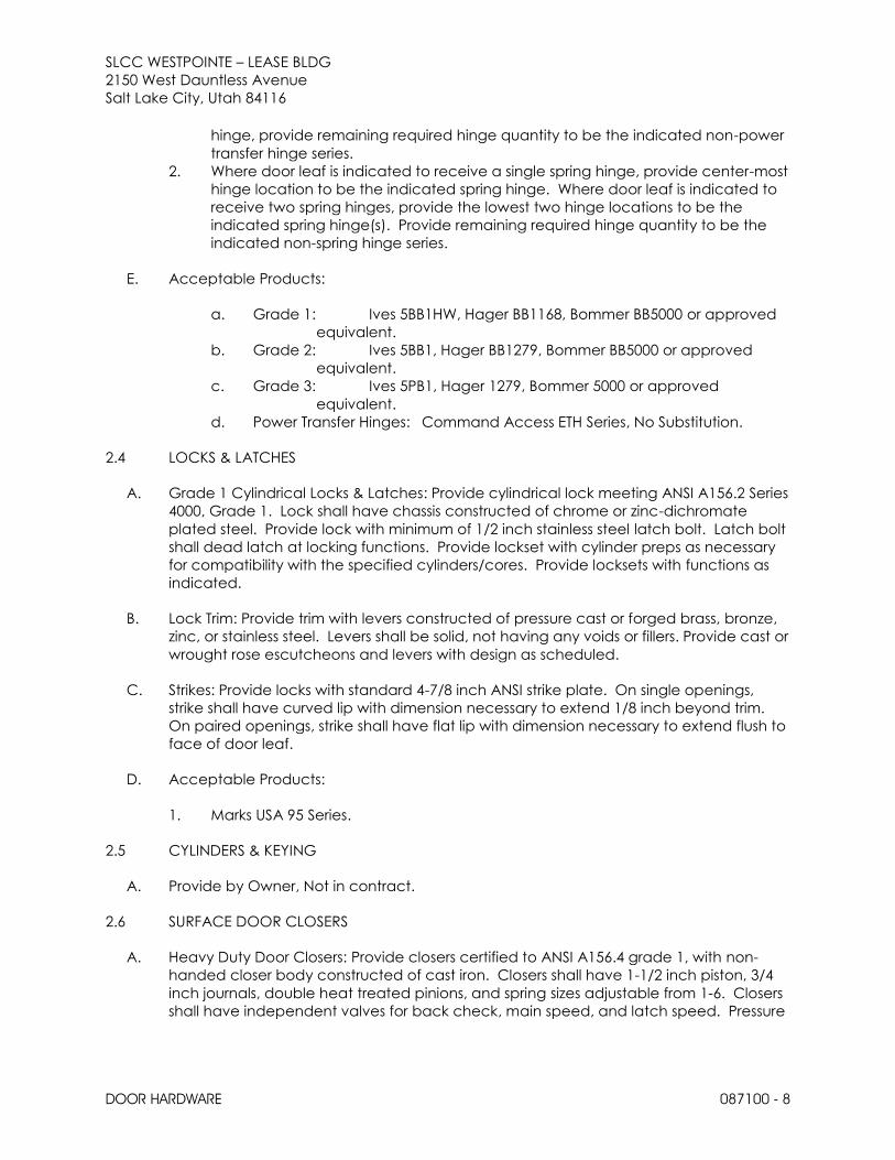
SLCC WESTPOINTE – LEASE BLDG 2150 West Dauntless Avenue
Salt Lake City, Utah 84116
DOOR HARDWARE 087100 - 8
hinge, provide remaining required hinge quantity to be the indicated non-power
transfer hinge series.
2. Where door leaf is indicated to receive a single spring hinge, provide center-most
hinge location to be the indicated spring hinge. Where door leaf is indicated to
receive two spring hinges, provide the lowest two hinge locations to be the
indicated spring hinge(s). Provide remaining required hinge quantity to be the
indicated non-spring hinge series.
E. Acceptable Products:
a. Grade 1: Ives 5BB1HW, Hager BB1168, Bommer BB5000 or approved
equivalent.
b. Grade 2: Ives 5BB1, Hager BB1279, Bommer BB5000 or approved
equivalent.
c. Grade 3: Ives 5PB1, Hager 1279, Bommer 5000 or approved
equivalent.
d. Power Transfer Hinges: Command Access ETH Series, No Substitution.
2.4 LOCKS & LATCHES
A. Grade 1 Cylindrical Locks & Latches: Provide cylindrical lock meeting ANSI A156.2 Series
4000, Grade 1. Lock shall have chassis constructed of chrome or zinc-dichromate
plated steel. Provide lock with minimum of 1/2 inch stainless steel latch bolt. Latch bolt
shall dead latch at locking functions. Provide lockset with cylinder preps as necessary
for compatibility with the specified cylinders/cores. Provide locksets with functions as
indicated.
B. Lock Trim: Provide trim with levers constructed of pressure cast or forged brass, bronze,
zinc, or stainless steel. Levers shall be solid, not having any voids or fillers. Provide cast or
wrought rose escutcheons and levers with design as scheduled.
C. Strikes: Provide locks with standard 4-7/8 inch ANSI strike plate. On single openings,
strike shall have curved lip with dimension necessary to extend 1/8 inch beyond trim.
On paired openings, strike shall have flat lip with dimension necessary to extend flush to
face of door leaf.
D. Acceptable Products:
1. Marks USA 95 Series.
2.5 CYLINDERS & KEYING
A. Provide by Owner, Not in contract.
2.6 SURFACE DOOR CLOSERS
A. Heavy Duty Door Closers: Provide closers certified to ANSI A156.4 grade 1, with non-
handed closer body constructed of cast iron. Closers shall have 1-1/2 inch piston, 3/4
inch journals, double heat treated pinions, and spring sizes adjustable from 1-6. Closers
shall have independent valves for back check, main speed, and latch speed. Pressure
SLCC WESTPOINTE – LEASE BLDG 2150 West Dauntless Avenue
Salt Lake City, Utah 84116
DOOR HARDWARE 087100 - 9
Relief Valves (PRVs) are prohibited. Closer shall be able to meet ADA opening force
requirements.
B. Provide closer arm as indicated in HW Sets. Where HW Sets indicate more than one
arm, provide the arm configuration that mounts the closer on the least public side of
door.
C. Acceptable Products:
1. LCN 4040XP Series.
2.7 DOOR PROTECTION
A. Provide protection plates constructed of .050 inch thick brass or stainless steel. Provide
plates with 4 beveled edges (B4E), and countersunk screw holes. Provide plates with
heights and widths as scheduled in the hardware sets.
B. Acceptable Products:
1. Ives 8400 Series, Hager 194 Series, Trimco K Series or approved equivalent.
2.8 DOOR STOPS & HOLDERS
A. General: Overhead stops shall be used at exterior doors not indicated to have stops
integrated into closer arms or at interior doors where door does not swing against a
wall. Wall stops shall be used at interior doors that swing against a masonry or
reinforced gypsum board wall. Where interior door swings against gypsum board wall
with no reinforcing, provide floor stop.
B. Overhead Stops: Provide overhead stops constructed of stainless steel that comply with
ANSI/BHMA A156.8 requirements. Size overhead stops in accordance with
manufacturer recommendations based on door leaf width. Provide stop with options
and accessories as scheduled. Provide special templating where required for
compatibility with other hardware scheduled for the opening.
C. Wall Stops & Holders: Provide stops constructed of cast brass or bronze that comply with
ANSI/BHMA A156.16 requirements. Wrought wall stops are not acceptable. Provide
concave bumpers where scheduled with cylindrical lockset functions utilizing push
buttons on the adjacent lever, otherwise provide convex bumpers. Provide stop with
fasteners appropriate to mount the stop based on the adjacent wall material.
D. Floor Stops & Holders: Provide universal dome floor stop constructed of either zinc or
stainless steel. Stop shall have a spring-loaded, replaceable rubber bumper.
E. Acceptable Products:
1. Interior Overhead Stops: Glynn Johnson 90S Series, Rixson 10 Series, ABH 3300 or
approved equivalent.
SLCC WESTPOINTE – LEASE BLDG 2150 West Dauntless Avenue
Salt Lake City, Utah 84116
DOOR HARDWARE 087100 - 10
2. Interior Wall Stops: Ives WS406/407CCV, Hager 236W, Trimco 1270 or approved
equivalent.
3. Interior Floor Stops: Ives FS439, Hager 242F, Trimco 1211 or approved equivalent.
2.9 THRESHOLDS & GASKETING
A. Thresholds: Provide thresholds of type and width as scheduled. Provide saddle
thresholds of continuous length equal to frame width from rabbet to rabbet, and panic
thresholds of continuous length equal to opening width plus frame face dimension.
Notch threshold as required to fit frame profile, miter and weld any exposed corners.
Where scheduled with floor closer, provide the appropriate preparation for
compatibility with the scheduled closer. Provide threshold with stainless steel fasteners
and lead anchors. Where heavy equipment will be moved over threshold, provide
threshold with no voids under the profile whether composite filled or solid extrusion.
B. Perimeter Gasketing: Provide gasketing of type scheduled with length as required to
provide a continuous seal between the door and frame without gaps. Provide any
required brackets or accessories to allow mounting of lock strikes, closer arms, or other
hardware without cutting or notching gasketing. Where openings are not provided
with perimeter gasket, provide silencers.
C. Astragals: Provide astragals as scheduled for mounting on the secure side of the
opening. If opening is reverse handed, astragal shall be provided to mount on pull side
of active leaf. If opening is regular handed, astragal shall be provided to mount on
push side of inactive leaf. Provide astragal with length equal to door height less 1 inch.
D. Meeting Stiles: Provide meeting stiles as scheduled with a length equal to door leaf
height less undercut dimension. For surface-mounted meeting stiles, provide one
meeting stile for each door leaf and mount on secure face of door.
E. Door Bottoms and Door Sweeps: Provide door bottoms and/or door sweeps as
scheduled with a length equal to door width.
F. Rain Drips: Provide rain drips at exterior openings. One rain drip shall be provided for
each exterior facing side of the opening. Rain drips shall have a continuous length
equal to the overall width of the frame.
G. Acceptable Products:
1. Zero International products as scheduled, equivalent products by National
Guard, Reese, or other approved manufacturers.
2.10 FINISHES
A. For hardware scheduled at storefront doors, provide hardware manufacturer’s
standard finish most closely matching the finish of adjacent storefront systems.
Otherwise, provide hardware manufacturer’s standard finish most closely matching the
indicated ANSI/BHMA A156.18 finish code for each hardware item.
PART 3 - EXECUTION
3.1 EXAMINATION

SLCC WESTPOINTE – LEASE BLDG 2150 West Dauntless Avenue
Salt Lake City, Utah 84116
DOOR HARDWARE 087100 - 11
A. Verify conditions of walls, flooring, doors, frames, and hardware are satisfactory for
installation of hardware. Conditions that do not allow proper installation of hardware
shall be corrected before proceeding.
3.2 INSTALLATION
A. General
1. Install door hardware as detailed in the approved hardware schedule using only
approved fasteners and in accordance with manufacturer’s recommended
procedures and methods.
2. Install hardware and signage at fire rated openings in accordance with NFPA 80
requirements.
B. Hardware Mounting Heights: Mount door hardware units at hollow metal door
manufacturer’s standard heights.
C. Surface Mounted Door Closers: Install surface mounted door closers on room side of
openings, except where prohibited by scheduled hardware. Use appropriate arms,
spacers, brackets, and accessories to properly install surface mounted door closers.
Adjust spring power to the appropriate setting to ensure the doors reliably close under
normal operating conditions.
D. Protection Plates: Where plates greater than 16 inches in height are to be installed on
fire rated openings, install using plate manufacturer’s recommended adhesive in lieu of
mechanical fasteners.
E. Wall Mounted Door Stops And Holders: Locate wall mounted door stops at the
appropriate height and location to properly contact protruding door trim.
F. Gasketing: Install gasketing to provide a continuous seal around the perimeter of the
opening. Install soffit mounted hardware using the proper brackets, spacers, and
accessories to allow proper installation without cutting or notching gasketing material
or mounting channels.
G. Overlapping Astragals
1. Install astragals at exterior doors using thru-bolts.
2. Where overlapping astragals are scheduled on out-swinging doors, provide for
mounting on the pull-side of the active leaf. Otherwise, provide for mounting on
the push-side of the inactive leaf.
3. Notching astragal is not acceptable. Where strike lip conflicts with astragal,
provide strike as specified in “Locks and Latches” article of this section.
H. Thresholds and Saddles: Trim, cut, and notch thresholds and saddles neatly to minimally
fit the profile of the door frame. Thresholds and saddles shall be set in full bed of butyl-
rubber or polyisobutylene mastic sealant.
3.3 FIELD QUALITY CONTROL

SLCC WESTPOINTE – LEASE BLDG 2150 West Dauntless Avenue
Salt Lake City, Utah 84116
DOOR HARDWARE 087100 - 12
A. Architectural Hardware Consultant: Architect will engage a qualified Architectural
Hardware Consultant to perform inspections and to prepare inspection reports.
B. Architectural Hardware Consultant will inspect door hardware and state in each report
whether installed work complies with or deviates from requirements, including whether
door hardware is properly installed and adjusted.
3.4 ADJUSTING
A. After building HVAC system is balanced and adjusted, conduct final adjustment of
door closers. Verify spring power of the surface mounted door closer is properly
adjusted to close and latch the door and to comply with the opening force
requirements of ANSI A117.1 as follows:
1. Doors with Closers shall take five (5) seconds to close from 90 degrees to 12
degrees.
2. Interior, non-fire rated swinging doors shall open with a maximum of 5 lbs of
pressure.
3. Exterior doors and fire rated doors shall open with the minimum amount of
pressure required to positively close and latch the door.
3.5 CLEANING AND PROTECTION
A. Clean adjacent surfaces soiled by door hardware installation. Clean operating items as
necessary to restore proper function and finish. Provide final protection and maintain
conditions that ensure that door hardware is without damage or deterioration at time
of Substantial Completion.
3.6 SCHEDULE
A. General:
1. The following schedule of hardware sets shall be considered a guide and the
supplier is cautioned to refer to general conditions, special conditions, and the full
requirements of this section. It shall be the hardware supplier's responsibility to
furnish all required hardware.
2. Where items of hardware are not definitely or correctly specified and are
required for completion of the Work, a written statement of such omission, error,
conflict, or other discrepancy shall be sent to the Architect, prior to date
specified for receipt of bids, for clarification by addendum.
3. Adjustments to the Contract Sum will not be allowed for omissions or items of
hardware not clarified prior to bid opening.

SLCC WESTPOINTE – LEASE BLDG 2150 West Dauntless Avenue
Salt Lake City, Utah 84116
DOOR HARDWARE 087100 - 13
B. Hardware Sets:
SpeXtra: 356634
HW SET: 01
DOOR NUMBER(S): 104, 105, 106, 107, 108, 109, 110, 116, 118, 125, 131, 132, 133, 134, 135, 139,
212, 214, 221, 226
1 EA INTERIOR HINGE SET 5BB1 SERIES 652 IVE
1 EA STOREROOM LOCK 195 F G3 626 MKS
1 SET CYLINDER(S) PROVIDED BY OWNER 626 B/O
1 EA ELECTRIC STRIKE 6211 FSE DS 630 VON
1 EA SURFACE CLOSER 4040XP EDA/REG TBWMS 689 LCN
1 EA KICK PLATE 8400 10" X 2" LDW B-CS 630 IVE
1 EA WALL STOP WS406/407CCV 630 IVE
1 EA PERIMETER SEALS 488S-BR DKB ZER
1 EA CARD READER PROVIDED BY OWNER TBD B/O
1 EA DOOR CONTACT 679-05 WHT SCE
1 SET CONDUIT & RACEWAY PROVIDED BY DIVISION 26 B/O
1 SET WIRING & CONNECTIONS PROVIDED BY OWNER B/O
1 EA LOW VOLTAGE POWER PROVIDED BY OWNER B/O
1 SET WIRING DIAGRAMS RISER/ELEVATION & SCHEMATIC VON
OPERATIONAL DESCRIPTION
1. UNDER NORMAL CONDITIONS, DOOR IS CLOSED AND LATCHED. DOOR IS SECURE AGAINST
UNAUTHORIZED ENTRY. INSIDE LEVER ALWAYS ALLOWS IMMEDIATE EGRESS.
2. AUTHORIZED ENTRY IS ALLOWED BY CARD AT OUTSIDE CARD READER WHICH MOMENTARILY
RELEASES ELECTRIC STRIKE TO ALLOW ENTRY.
3. ON LOSS OF POWER, DOOR REMAINS CLOSED, LATCHED, AND SECURE AGAINST
UNAUTHORIZED ENTRY. EMERGENCY ENTRY IS ALLOWED BY KEY IN OUTSIDE CYLIN
HW SET: 02
DOOR NUMBER(S): 202
1 EA INTERIOR HINGE SET 5BB1 SERIES 652 IVE
1 EA PUSH PLATE 8200 6" X 16" 630 IVE
1 EA PULL PLATE 8305 8" 4" X 16" 630 IVE
1 EA SURFACE CLOSER 4040XP EDA/REG TBWMS 689 LCN
1 EA KICK PLATE 8400 10" X 2" LDW B-CS 630 IVE
1 EA WALL STOP WS406/407CCV 630 IVE
1 EA PERIMETER SEALS 488S-BR DKB ZER

SLCC WESTPOINTE – LEASE BLDG 2150 West Dauntless Avenue
Salt Lake City, Utah 84116
DOOR HARDWARE 087100 - 14
HW SET: 03
DOOR NUMBER(S): 240, 241
1 EA INTERIOR HINGE SET 5BB1 SERIES 652 IVE
1 EA PASSAGE LATCH 195 N 626 MKS
1 EA KICK PLATE 8400 10" X 2" LDW B-CS 630 IVE
1 EA WALL STOP WS406/407CCV 630 IVE
1 EA PERIMETER SEALS 488S-BR DKB ZER
End of Section 087100

SLCC WESTPOINTE – LEASE BLDG 2150 West Dauntless Avenue
Salt Lake City, Utah 84116
GLAZING 088000 - 1
SECTION 088000 - GLAZING
PART 1 - GENERAL
1.1 RELATED DOCUMENTS
A. Drawings and general provisions of the Contract, including General and
Supplementary Conditions and Division 01 Specification Sections, apply to this Section.
1.2 SUMMARY
A. Section includes glazing for the following products and applications, including those
specified in other Sections where glazing requirements are specified by reference to
this Section:
1. Doors.
2. Storefront Framing.
3. Glazed Entrances.
4. Fire-Rated Safety Glazing
B. Related Sections:
1. Section 084113 “Aluminum Framed Storefronts and Entrances”.
2. Section 0881113 “Hollow Metal Doors and Frames”.
3. Section 0881416 “Flush Wood Doors”.
4. Section 081433 “Stile and Rail Doors”.
1.3 DEFINITIONS
A. Glass Manufacturers: Firms that produce primary glass, fabricated glass, or both, as
defined in referenced glazing publications.
B. Glass Thicknesses: Indicated by thickness designations in millimeters according to
ASTM C 1036.
C. Interspace: Space between lites of an insulating-glass unit.
1.4 PERFORMANCE REQUIREMENTS
A. General: Installed glazing systems shall withstand normal thermal movement and wind
and impact loads (where applicable) without failure, including loss or glass breakage
attributable to the following: defective manufacture, fabrication, or installation; failure
of sealants or gaskets to remain watertight and airtight; deterioration of glazing
materials; or other defects in construction.
SLCC WESTPOINTE – LEASE BLDG 2150 West Dauntless Avenue
Salt Lake City, Utah 84116
GLAZING 088000 - 2
1.5 SUBMITTALS
A. Product Data: For each glass product and glazing material indicated.
B. Glass Samples: For each type of the following products, where indicated; 12 inches
(300 mm) square.
1. Coated glass.
2. Fire-resistive glazing products.
3. Insulating glass.
4. One-Way Vision glass
C. Glazing Accessory Samples: For gaskets, sealants and colored spacers, in 12-inch (300-
mm) lengths.
D. Glazing Schedule: List glass types and thicknesses for each size opening and location.
Use same designations indicated on Drawings.
E. Delegated-Design Submittal: For glass indicated to comply with performance
requirements and design criteria, including analysis data signed and sealed by the
qualified professional engineer responsible for their preparation.
F. Qualification Data: For installers.
G. Product Certificates: For glass and glazing products, from manufacturer.
H. Product Test Reports: Based on evaluation of comprehensive tests performed by a
qualified testing agency, for tinted glass, coated glass, insulating glass, glazing sealants
and glazing gaskets.
1. For glazing sealants, provide test reports based on testing current sealant
formulations within previous 36-month period.
I. Preconstruction adhesion and compatibility test report.
J. Warranties: Sample of special warranties.
1.6 QUALITY ASSURANCE
A. Manufacturer Qualifications for Insulating-Glass Units with Sputter-Coated, Low-E
Coatings: A qualified insulating-glass manufacturer who is approved and certified by
coated-glass manufacturer.
B. Installer Qualifications: A qualified installer who employs glass installers for this Project
who are certified under the National Glass Association's Certified Glass Installer
Program.
C. Glass Testing Agency Qualifications: A qualified independent testing agency
accredited according to the NFRC CAP 1 Certification Agency Program.

SLCC WESTPOINTE – LEASE BLDG 2150 West Dauntless Avenue
Salt Lake City, Utah 84116
GLAZING 088000 - 3
D. Sealant Testing Agency Qualifications: An independent testing agency qualified
according to ASTM C 1021 to conduct the testing indicated.
E. Source Limitations for Glass: Obtain ultraclear float glass, coated float glass, and
insulating glass from single source from single manufacturer for each glass type.
F. Source Limitations for Glazing Accessories: Obtain from single source from single
manufacturer for each product and installation method.
G. Glazing Publications: Comply with published recommendations of glass product
manufacturers and organizations below, unless more stringent requirements are
indicated. Refer to these publications for glazing terms not otherwise defined in this
Section or in referenced standards.
1. IGMA Publication for Insulating Glass: SIGMA TM-3000, "North American Glazing
Guidelines for Sealed Insulating Glass Units for Commercial and Residential Use."
H. Safety Glazing Labeling: Where safety glazing labeling is indicated, permanently mark
glazing with certification label of the SGCC or another certification agency
acceptable to authorities having jurisdiction or the manufacturer. Label shall indicate
manufacturer's name, type of glass, thickness, and safety glazing standard with which
glass complies.
I. Fire-Protection-Rated Glazing Labeling: Permanently mark fire-protection-rated glazing
with certification label of a testing agency acceptable to authorities having jurisdiction.
Label shall indicate manufacturer's name, test standard, whether glazing is for use in fire
doors or other openings, whether or not glazing passes hose-stream test, whether or not
glazing has a temperature rise rating of 450 deg F (250 deg C), and the fire-resistance
rating in minutes.
J. Insulating-Glass Certification Program: Permanently marked either on spacers or on at
least one component lite of units with appropriate certification label of IGCC.
K. Mockups: Build mockups to verify selections made under sample submittals and to
demonstrate aesthetic effects and set quality standards for materials and execution.
1. Install glazing in mockups specified in Division 08 Section "Aluminum-Framed
Entrances and Storefronts, Glazed Aluminum Curtain Walls" to match glazing
systems required for Project, including glazing methods.
2. Approved mockups may become part of the completed Work if undisturbed at
time of Substantial Completion.
L. Preinstallation Conference: Conduct conference at Project site.
1. Review and finalize construction schedule and verify availability of materials,
Installer's personnel, equipment, and facilities needed to make progress and
avoid delays.
2. Review temporary protection requirements for glazing during and after
installation.

SLCC WESTPOINTE – LEASE BLDG 2150 West Dauntless Avenue
Salt Lake City, Utah 84116
GLAZING 088000 - 4
1.7 DELIVERY, STORAGE, AND HANDLING
A. Protect glazing materials according to manufacturer's written instructions. Prevent
damage to glass and glazing materials from condensation, temperature changes,
direct exposure to sun, or other causes.
B. Comply with insulating-glass manufacturer's written recommendations for venting and
sealing units to avoid hermetic seal ruptures due to altitude change.
1.8 PROJECT CONDITIONS
A. Environmental Limitations: Do not proceed with glazing when ambient and substrate
temperature conditions are outside limits permitted by glazing material manufacturers
and when glazing channel substrates are wet from rain, frost, condensation, or other
causes.
1. Do not install glazing sealants when ambient and substrate temperature
conditions are outside limits permitted by sealant manufacturer or below 40 deg F
(4.4 deg C).
1.9 WARRANTY
A. Manufacturer's Special Warranty on Fire-resistive glazing: Manufacturer's standard form
in which Fire-resistive glazing manufacturer agrees to replace Fire-resistive glazing units
that deteriorate within specified warranty period. Deterioration of Fire-resistive glazing is
defined as failure of hermetic seal under normal use that is not attributed to glass
breakage or to maintaining and cleaning Fire-resistive glazing contrary to
manufacturer's written instructions. Evidence of failure is the obstruction of vision by
dust, moisture, or film.
1. Warranty Period: 10 years from date of Substantial Completion
PART 2 - PRODUCTS
2.1 GLASS PRODUCTS, GENERAL
A. Thickness: Where glass thickness is indicated, it is a minimum. Provide glass lites in
thicknesses as needed to comply with requirements indicated.
1. Minimum Glass Thickness for Lites: Not less than 6.0 mm.
2. Thickness of Tinted Glass: Provide same thickness for each tint color indicated
throughout Project.
B. Strength: Where float glass is indicated, provide annealed float glass, Kind HS heat-
treated float glass, or Kind FT heat-treated float glass as needed to comply with
"Performance Requirements" Article. Where heat-strengthened glass is indicated,
provide Kind HS heat-treated float glass or Kind FT heat-treated float glass as needed to

SLCC WESTPOINTE – LEASE BLDG 2150 West Dauntless Avenue
Salt Lake City, Utah 84116
GLAZING 088000 - 5
comply with "Performance Requirements" Article. Where fully tempered glass is
indicated, provide Kind FT heat-treated float glass.
2.2 GLASS PRODUCTS
A. Float Glass: ASTM C 1036, Type I, Quality-Q3, Class I (clear) unless otherwise indicated.
B. Clear Float Glass: ASTM C 1036, Type I, Quality-Q3, Class I, complying with other
requirements specified and with visible light transmission not less than 54 percent.
1. Products: Subject to compliance with requirements, provide one of the following:
a. AFG Industries, Inc.
b. Guardian Industries Corp.
c. Pilkington North America
d. PPG Industries, Inc.
e. Viracon.
A. Fully Tempered Float Glass: ASTM C 1048, Kind FT fully tempered, Condition A,
uncoated, Type I, Class 1 (clear), Quality-Q3.
1. Fabrication Process: By horizontal (roller-hearth) process with roll-wave distortion
parallel to bottom edge of glass as installed unless otherwise indicated.
2.3 FIRE-PROTECTION-RATED GLAZING
A. Fire-Protection-Rated Glazing, General: Listed and labeled by a testing agency
acceptable to authorities having jurisdiction, for fire-protection ratings indicated, based
on testing according to NFPA 257 for window assemblies.
B. Gel-Filled, Double Glazing Units: Double glazing units made from two lites of uncoated,
clear, fully tempered float glass; with a perimeter metal spacer separating lites and
dual-edge seal enclosing a cavity filled with clear, fully transparent, heat-absorbing gel;
complying with testing requirements in 16 CFR 1201 for Category II materials.
1. Fire rating: 45 minutes and 20 minutes.
2. Products: Subject to compliance with requirements, available products that may
be incorporated into the Work include, but are not limited to, the following:
a. Safti First; SuperLite II.
b. Approved equal.
2.4 GLAZING GASKETS
A. Dense Compression Gaskets: Molded or extruded gaskets of profile and hardness
required to maintain watertight seal, made from one of the following:
1. Neoprene complying with ASTM C 864.
2. EPDM complying with ASTM C 864.

SLCC WESTPOINTE – LEASE BLDG 2150 West Dauntless Avenue
Salt Lake City, Utah 84116
GLAZING 088000 - 6
3. Silicone complying with ASTM C 1115.
4. Thermoplastic polyolefin rubber complying with ASTM C 1115.
B. Soft Compression Gaskets: Extruded or molded, closed-cell, integral-skinned neoprene,
EPDM, silicone, or thermoplastic polyolefin rubber gaskets complying with ASTM C 509,
Type II, black; of profile and hardness required to maintain watertight seal.
1. Application: Use where soft compression gaskets will be compressed by inserting
dense compression gaskets on opposite side of glazing or pressure applied by
means of pressure-glazing stops on opposite side of glazing.
C. Lock-Strip Gaskets: Neoprene extrusions in size and shape indicated, fabricated into
frames with molded corner units and zipper lock-strips, complying with ASTM C 542,
black.
2.5 GLAZING SEALANTS
A. General:
1. Compatibility: Provide glazing sealants that are compatible with one another
and with other materials they will contact, including glass products, seals of
insulating-glass units, and glazing channel substrates, under conditions of service
and application, as demonstrated by sealant manufacturer based on testing and
field experience.
2. Suitability: Comply with sealant and glass manufacturers' written instructions for
selecting glazing sealants suitable for applications indicated and for conditions
existing at time of installation.
3. VOC Content: For sealants used inside of the weatherproofing system, not more
than 250 g/L when calculated according to 40 CFR 59, Subpart D.
4. Colors of Exposed Glazing Sealants: As selected by Architect from manufacturer's
full range.
B. Glazing Sealant: Neutral-curing silicone glazing sealant complying with ASTM C 920,
Type S, Grade NS, Class 100/50, Use NT.
1. Products: Subject to compliance with requirements, provide one of the following:
a. Dow Corning Corporation; 790.
b. GE Advanced Materials - Silicones; SilPruf LM SCS2700.
c. May National Associates, Inc.; Bondaflex Sil 290.
d. Pecora Corporation; 890.
e. Sika Corporation, Construction Products Division; SikaSil-C990.
f. Tremco Incorporated; Spectrem 1.
C. Glazing Sealants for Fire-Rated Glazing Products: Products that are approved by
testing agencies that listed and labeled fire-resistant glazing products with which they
are used for applications and fire-protection ratings indicated.

SLCC WESTPOINTE – LEASE BLDG 2150 West Dauntless Avenue
Salt Lake City, Utah 84116
GLAZING 088000 - 7
2.6 GLAZING TAPES
A. Back-Bedding Mastic Glazing Tapes: Preformed, butyl-based, 100 percent solids
elastomeric tape; nonstaining and nonmigrating in contact with nonporous surfaces;
with or without spacer rod as recommended in writing by tape and glass
manufacturers for application indicated; and complying with ASTM C 1281 and
AAMA 800 for products indicated below:
1. AAMA 804.3 tape, where indicated.
2. AAMA 806.3 tape, for glazing applications in which tape is subject to continuous
pressure.
3. AAMA 807.3 tape, for glazing applications in which tape is not subject to
continuous pressure.
B. Expanded Cellular Glazing Tapes: Closed-cell, PVC foam tapes; factory coated with
adhesive on both surfaces; and complying with AAMA 800 for the following types:
1. AAMA 810.1, Type 1, for glazing applications in which tape acts as the primary
sealant.
2. AAMA 810.1, Type 2, for glazing applications in which tape is used in combination
with a full bead of liquid sealant.
2.7 MISCELLANEOUS GLAZING MATERIALS
A. General: Provide products of material, size, and shape complying with referenced
glazing standard, requirements of manufacturers of glass and other glazing materials for
application indicated, and with a proven record of compatibility with surfaces
contacted in installation.
B. Cleaners, Primers, and Sealers: Types recommended by sealant or gasket
manufacturer.
C. Setting Blocks: Elastomeric material with a Shore, Type A durometer hardness of 85, plus
or minus 5.
D. Spacers: Elastomeric blocks or continuous extrusions of hardness required by glass
manufacturer to maintain glass lites in place for installation indicated.
E. Edge Blocks: Elastomeric material of hardness needed to limit glass lateral movement
(side walking).
F. Cylindrical Glazing Sealant Backing: ASTM C 1330, Type O (open-cell material), of size
and density to control glazing sealant depth and otherwise produce optimum glazing
sealant performance.
G. Perimeter Insulation for Fire-Resistive Glazing: Product that is approved by testing
agency that listed and labeled fire-resistant glazing product with which it is used for
application and fire-protection rating indicated.

SLCC WESTPOINTE – LEASE BLDG 2150 West Dauntless Avenue
Salt Lake City, Utah 84116
GLAZING 088000 - 8
2.8 FABRICATION OF GLAZING UNITS
A. Fabricate glazing units in sizes required to fit openings indicated for Project, with edge
and face clearances, edge and surface conditions, and bite complying with written
instructions of product manufacturer and referenced glazing publications, to comply
with system performance requirements.
B. Clean-cut or flat-grind vertical edges of butt-glazed monolithic lites to produce square
edges with slight chamfers at junctions of edges and faces.
C. Grind smooth and polish exposed glass edges and corners.
PART 3 - EXECUTION
3.1 EXAMINATION
A. Examine framing, glazing channels, and stops, with Installer present, for compliance
with the following:
1. Manufacturing and installation tolerances, including those for size, squareness,
and offsets at corners.
2. Presence and functioning of weep systems.
3. Minimum required face and edge clearances.
4. Effective sealing between joints of glass-framing members.
B. Proceed with installation only after unsatisfactory conditions have been corrected.
3.2 PREPARATION
A. Clean glazing channels and other framing members receiving glass immediately before
glazing. Remove coatings not firmly bonded to substrates.
B. Examine glazing units to locate interior surfaces. Label or mark units as needed so that
interior surfaces are readily identifiable. Do not use materials that will leave visible
marks in the completed work.
3.3 GLAZING, GENERAL
A. Comply with combined written instructions of manufacturers of glass, sealants, gaskets,
and other glazing materials, unless more stringent requirements are indicated, including
those in referenced glazing publications.
B. Adjust glazing channel dimensions as required by Project conditions during installation
to provide necessary bite on glass, minimum edge and face clearances, and
adequate sealant thicknesses, with reasonable tolerances.
C. Protect glass edges from damage during handling and installation. Remove damaged
glass from Project site and legally dispose of off Project site. Damaged glass is glass
SLCC WESTPOINTE – LEASE BLDG 2150 West Dauntless Avenue
Salt Lake City, Utah 84116
GLAZING 088000 - 9
with edge damage or other imperfections that, when installed, could weaken glass
and impair performance and appearance.
D. Apply primers to joint surfaces where required for adhesion of sealants, as determined
by preconstruction testing.
E. Install setting blocks in sill rabbets, sized and located to comply with referenced glazing
publications, unless otherwise required by glass manufacturer. Set blocks in thin course
of compatible sealant suitable for heel bead.
F. Do not exceed edge pressures stipulated by glass manufacturers for installing glass lites.
G. Provide spacers for glass lites where length plus width is larger than 50 inches (1270
mm).
1. Locate spacers directly opposite each other on both inside and outside faces of
glass. Install correct size and spacing to preserve required face clearances,
unless gaskets and glazing tapes are used that have demonstrated ability to
maintain required face clearances and to comply with system performance
requirements.
2. Provide 1/8-inch (3-mm) minimum bite of spacers on glass and use thickness
equal to sealant width. With glazing tape, use thickness slightly less than final
compressed thickness of tape.
H. Provide edge blocking where indicated or needed to prevent glass lites from moving
sideways in glazing channel, as recommended in writing by glass manufacturer and
according to requirements in referenced glazing publications.
I. Set glass lites in each series with uniform pattern, draw, bow, and similar characteristics.
J. Set glass lites with proper orientation so that coatings face interior as specified.
K. Where wedge-shaped gaskets are driven into one side of channel to pressurize sealant
or gasket on opposite side, provide adequate anchorage so gasket cannot walk out
when installation is subjected to movement.
L. Square cut wedge-shaped gaskets at corners and install gaskets in a manner
recommended by gasket manufacturer to prevent corners from pulling away; seal
corner joints and butt joints with sealant recommended by gasket manufacturer.
3.4 TAPE GLAZING
A. Position tapes on fixed stops so that, when compressed by glass, their exposed edges
are flush with or protrude slightly above sightline of stops.
B. Install tapes continuously, but not necessarily in one continuous length. Do not stretch
tapes to make them fit opening.
C. Cover vertical framing joints by applying tapes to heads and sills first and then to jambs.
Cover horizontal framing joints by applying tapes to jambs and then to heads and sills.
SLCC WESTPOINTE – LEASE BLDG 2150 West Dauntless Avenue
Salt Lake City, Utah 84116
GLAZING 088000 - 10
D. Place joints in tapes at corners of opening with adjoining lengths butted together, not
lapped. Seal joints in tapes with compatible sealant approved by tape manufacturer.
E. Do not remove release paper from tape until right before each glazing unit is installed.
F. Apply heel bead of elastomeric sealant.
G. Center glass lites in openings on setting blocks and press firmly against tape by inserting
dense compression gaskets formed and installed to lock in place against faces of
removable stops. Start gasket applications at corners and work toward centers of
openings.
H. Apply cap bead of elastomeric sealant over exposed edge of tape.
3.5 GASKET GLAZING (DRY - Contractors Option)
A. Cut compression gaskets to lengths recommended by gasket manufacturer to fit
openings exactly, with allowance for stretch during installation.
B. Insert soft compression gasket between glass and frame or fixed stop so it is securely in
place with joints miter cut and bonded together at corners.
C. Installation with Drive-in Wedge Gaskets: Center glass lites in openings on setting blocks
and press firmly against soft compression gasket by inserting dense compression gaskets
formed and installed to lock in place against faces of removable stops. Start gasket
applications at corners and work toward centers of openings. Compress gaskets to
produce a weathertight seal without developing bending stresses in glass. Seal gasket
joints with sealant recommended by gasket manufacturer.
D. Installation with Pressure-Glazing Stops: Center glass lites in openings on setting blocks
and press firmly against soft compression gasket. Install dense compression gaskets and
pressure-glazing stops, applying pressure uniformly to compression gaskets. Compress
gaskets to produce a weathertight seal without developing bending stresses in glass.
Seal gasket joints with sealant recommended by gasket manufacturer.
E. Install gaskets so they protrude past face of glazing stops.
3.6 SEALANT GLAZING (WET - Contractors Option)
A. Install continuous spacers, or spacers combined with cylindrical sealant backing,
between glass lites and glazing stops to maintain glass face clearances and to prevent
sealant from extruding into glass channel and blocking weep systems until sealants
cure. Secure spacers or spacers and backings in place and in position to control depth
of installed sealant relative to edge clearance for optimum sealant performance.
B. Force sealants into glazing channels to eliminate voids and to ensure complete wetting
or bond of sealant to glass and channel surfaces.
C. Tool exposed surfaces of sealants to provide a substantial wash away from glass.

SLCC WESTPOINTE – LEASE BLDG 2150 West Dauntless Avenue
Salt Lake City, Utah 84116
GLAZING 088000 - 11
3.7 LOCK-STRIP GASKET GLAZING
A. Comply with ASTM C 716 and gasket manufacturer's written instructions. Provide
supplementary wet seal and weep system unless otherwise indicated.
3.8 CLEANING AND PROTECTION
A. Protect glass from damage immediately after installation by attaching crossed
streamers to framing held away from glass. Do not apply markers to glass surface.
Remove nonpermanent labels and clean surfaces.
B. Protect glass from contact with contaminating substances resulting from construction
operations. If, despite such protection, contaminating substances do come into
contact with glass, remove substances immediately as recommended in writing by
glass manufacturer.
C. Remove and replace glass that is broken, chipped, cracked, or abraded or that is
damaged from natural causes, accidents, and vandalism, during construction period.
D. Wash glass on both exposed surfaces in each area of Project not more than four days
before date scheduled for inspections that establish date of Substantial Completion.
Wash glass as recommended in writing by glass manufacturer.
END OF SECTION 088000

SLCC WESTPOINTE – LEASE BLDG 2150 West Dauntless Avenue
Salt Lake City, Utah 84116
GLAZING 088000 - 12
THIS PAGE IS INTENTIONALLY LEFT BLANK

SLCC WESTPOINTE – LEASE BLDG 2150 West Dauntless Avenue
Salt Lake City, Utah 84116
NON-STRUCTURAL METAL FRAMING 092216 - 1
SECTION 092216 - NON-STRUCTURAL METAL FRAMING
PART 1 - GENERAL
1.1 RELATED DOCUMENTS
A. Drawings and general provisions of the Contract, including General and
Supplementary Conditions and Division 01 Specification Sections, apply to this Section.
1.2 SUMMARY
A. Section Includes:
1. Non-load-bearing steel framing systems for interior gypsum board assemblies.
2. Suspension systems for interior gypsum ceilings, soffits, and grid systems.
B. Related Sections include the following:
1. Section 061050 “Miscellaneous Carpentry”, for blocking.
2. Section 092900 "Gypsum Board" for gypsum board installed over metal studs.
1.3 ACTION SUBMITTALS
A. Product Data: For each type of product.
1.4 INFORMATIONAL SUBMITTALS
A. Evaluation Reports: For dimpled steel studs and runners and firestop tracks, from ICC-ES.
PART 2 - PRODUCTS
2.1 PERFORMANCE REQUIREMENTS
A. Fire-Test-Response Characteristics: For fire-resistance-rated assemblies that incorporate
non-load-bearing steel framing, provide materials and construction identical to those
tested in assembly indicated, according to ASTM E 119 by an independent testing
agency.
B. STC-Rated Assemblies: For STC-rated assemblies, provide materials and construction
identical to those tested in assembly indicated, according to ASTM E 90 and classified
according to ASTM E 413 by an independent testing agency.

SLCC WESTPOINTE – LEASE BLDG 2150 West Dauntless Avenue
Salt Lake City, Utah 84116
NON-STRUCTURAL METAL FRAMING 092216 - 2
2.2 FRAMING SYSTEMS
A. Framing Members, General: Comply with ASTM C 754 for conditions indicated.
1. Steel Sheet Components: Comply with ASTM C 645 requirements for metal unless
otherwise indicated. Minimum Base-Metal Thickness: Minimum 20 gauge.
2. Protective Coating: G60 (Z180), A60 (ZF180) hot-dip galvanized unless otherwise
indicated.
B. Studs and Runners: ASTM C 645. Use either steel studs and runners or dimpled steel
studs and runners.
1. Steel Studs and Runners:
a. Minimum Base-Metal Thickness: Minimum 20 gauge.
b. Depth: As indicated on Drawings.
C. Slip-Type Head Joints: Where indicated, provide one of the following:
1. Single Long-Leg Runner System: ASTM C 645 top runner with 2-inch- deep flanges
in thickness not less than indicated for studs, installed with studs friction fit into top
runner and with continuous bridging located within 12 inches (305 mm) of the top
of studs to provide lateral bracing.
2. Deflection Track: Steel sheet top runner manufactured to prevent cracking of
finishes applied to interior partition framing resulting from deflection of structure
above; in thickness not less than indicated for studs and in width to
accommodate depth of studs.
3. Minimum Base-Metal Thickness: Minimum 20 gauge.
a. Products: Subject to compliance with requirements, provide one of the
following:
1) Dietrich Metal Framing; SLP-TRK Slotted Deflection Track.
2) MBA Building Supplies; FlatSteel Deflection Track or Slotted Deflecto
Track.
3) Steel Network Inc. (The); VertiTrack VTD Series.
4) Superior Metal Trim; Superior Flex Track System (SFT).
5) Telling Industries; Vertical Slip Track or Vertical Slip Track II.
6) Approved equal.
D. Flat Strap and Backing Plate: Steel sheet for blocking and bracing in length and width
indicated.
1. Minimum Base-Metal Thickness: Minimum 20 gauge.
E. Cold-Rolled Channel Bridging: Steel, 0.053-inch minimum base-metal thickness, with
minimum 1/2-inch- wide flanges.
1. Depth: 1-1/2 inches unless otherwise indicated.
2. Clip Angle: Not less than 1-1/2 by 1-1/2 inches, 0.068-inch- thick, galvanized steel.
SLCC WESTPOINTE – LEASE BLDG 2150 West Dauntless Avenue
Salt Lake City, Utah 84116
NON-STRUCTURAL METAL FRAMING 092216 - 3
F. Cold-Rolled Furring Channels: 0.053-inch uncoated-steel thickness, with minimum 1/2-
inch- (13-mm-) wide flanges.
1. Depth: 3/4 inch unless otherwise indicated.
2. Furring Brackets: Adjustable, corrugated-edge type of steel sheet with minimum
uncoated-steel thickness of 0.033 inch.
3. Tie Wire: ASTM A 641/A 641M, Class 1 zinc coating, soft temper, 0.062-inch-
diameter wire, or double strand of 0.048-inch- diameter wire.
2.3 SUSPENSION SYSTEMS Retain this article for suspended or furred ceilings or soffits.
A. Tie Wire: ASTM A 641/A 641M, Class 1 zinc coating, soft temper, 0.062-inch- diameter
wire, or double strand of 0.048-inch- diameter wire. Increase wire size as required for
heavier ceiling systems.
B. Wire Hangers: ASTM A 641/A 641M, Class 1 zinc coating, soft temper, 0.16 inch in
diameter.
C. Flat Hangers: Steel sheet, 1 by 3/16 inch by length indicated.
D. Carrying Channels: Cold-rolled, commercial-steel sheet with a base-metal thickness of
0.053 inch and minimum 1/2-inch- wide flanges.
1. Depth: 1-1/2 inches unless otherwise indicated.
E. Furring Channels (Furring Members):
1. Cold-Rolled Channels: 0.053-inch uncoated-steel thickness, with minimum 1/2-
inch- wide flanges, 3/4 inch deep.
2. Steel Studs and Runners: ASTM C 645.
a. Minimum Base-Metal Thickness: 0.033 inch unless otherwise indicated.
b. Depth: 1-5/8 inches unless otherwise indicated.
3. Hat-Shaped, Rigid Furring Channels: ASTM C 645, 7/8 inch deep.
a. Minimum Base-Metal Thickness: 0.033 inch unless otherwise indicated.
4. Resilient Furring Channels: 1/2-inch- deep members designed to reduce sound
transmission.
a. Configuration: Asymmetrical or hat shaped.
F. Grid Suspension System for Gypsum Board Ceilings: ASTM C 645, direct-hung system
composed of main beams and cross-furring members that interlock.
1. Products: Subject to compliance with requirements, provide one of the following:
a. Armstrong World Industries, Inc.; Drywall Grid Systems.
b. Chicago Metallic Corporation; Drywall Grid System.
c. USG Corporation; Drywall Suspension System.

SLCC WESTPOINTE – LEASE BLDG 2150 West Dauntless Avenue
Salt Lake City, Utah 84116
NON-STRUCTURAL METAL FRAMING 092216 - 4
2.4 AUXILIARY MATERIALS
A. General: Provide auxiliary materials that comply with referenced installation standards.
1. Fasteners for Metal Framing: Of type, material, size, corrosion resistance, holding
power, and other properties required to fasten steel members to substrates.
PART 3 - EXECUTION
3.1 EXAMINATION
A. Examine areas and substrates, with Installer present, and including welded hollow-metal
frames, cast-in anchors, and structural framing, for compliance with requirements and
other conditions affecting performance of the Work.
B. Proceed with installation only after unsatisfactory conditions have been corrected.
3.2 PREPARATION
A. Suspended Assemblies: Coordinate installation of suspension systems with installation of
overhead structure to ensure that inserts and other provisions for anchorages to
building structure have been installed to receive hangers at spacing required to
support the Work and that hangers will develop their full strength.
1. Furnish concrete inserts and other devices indicated to other trades for installation
in advance of time needed for coordination and construction.
3.3 INSTALLATION, GENERAL
A. Installation Standard: ASTM C 754.
1. Gypsum Board Assemblies: Also comply with requirements in ASTM C 840 that
apply to framing installation.
B. Install supplementary framing, and blocking to support fixtures, equipment services,
heavy trim, grab bars, toilet accessories, furnishings, or similar construction.
C. Install bracing at terminations in assemblies.
D. Do not bridge building control and expansion joints with non-load-bearing steel framing
members. Frame both sides of joints independently.
3.4 INSTALLING FRAMED ASSEMBLIES
A. Install framing system components according to spacings indicated, but not greater
than spacings required by referenced installation standards for assembly types.

SLCC WESTPOINTE – LEASE BLDG 2150 West Dauntless Avenue
Salt Lake City, Utah 84116
NON-STRUCTURAL METAL FRAMING 092216 - 5
1. Single-Layer Application: 16 inches o.c. unless otherwise indicated.
2. Multilayer Application: 16 inches o.c. unless otherwise indicated.
3. Tile Backing Panels: 16 inches o.c. unless otherwise indicated.
B. Where studs are installed directly against exterior masonry walls or dissimilar metals at
exterior walls, install isolation strip between studs and exterior wall.
C. Install studs so flanges within framing system point in same direction.
D. Install tracks (runners) at floors and overhead supports. Extend framing full height to
structural supports or substrates above suspended ceilings except where partitions are
indicated to terminate at suspended ceilings. Continue framing around ducts
penetrating partitions above ceiling.
1. Slip-Type Head Joints: Where framing extends to overhead structural supports,
install to produce joints at tops of framing systems that prevent axial loading of
finished assemblies.
2. Door Openings: Screw vertical studs at jambs to jamb anchor clips on door
frames; install runner track section (for cripple studs) at head and secure to jamb
studs.
a. Install two studs at each jamb unless otherwise indicated.
b. Install cripple studs at head adjacent to each jamb stud, with a minimum
1/2-inch (13-mm) clearance from jamb stud to allow for installation of
control joint in finished assembly.
c. Extend jamb studs through suspended ceilings and attach to underside of
overhead structure.
3. Door Openings: Screw vertical studs at jambs to jamb anchor clips on door
frames; install runner track section (for cripple studs) at head and secure to jamb
studs.
a. Install two 18 gauge studs at each jamb, both sides.
b. Install cripple studs at head adjacent to each jamb stud, with a minimum
1/2-inch (12.7-mm) clearance from jamb stud to allow for installation of
control joint in finished assembly.
c. Extend jamb studs for doors and side light through to and attach to
underside of overhead structure.
4. Other Framed Openings: Frame openings other than door openings the same as
required for door openings.
5. Sound-Rated Partitions: Install framing to comply with sound-rated assembly.
E. Installation Tolerance: Install each framing member so fastening surfaces vary not more
than 1/8 inch (3 mm) from the plane formed by faces of adjacent framing.
3.5 INSTALLING SUSPENSION SYSTEMS
A. Install suspension system components according to spacings indicated, but not greater
than spacings required by referenced installation standards for assembly types.

SLCC WESTPOINTE – LEASE BLDG 2150 West Dauntless Avenue
Salt Lake City, Utah 84116
NON-STRUCTURAL METAL FRAMING 092216 - 6
1. Hangers: 48 inches (1219 mm) o.c.
2. Carrying Channels (Main Runners): 48 inches (1219 mm) o.c.
3. Furring Channels (Furring Members): 24 inches (610 mm) o.c.
B. Isolate suspension systems from building structure where they abut or are penetrated by
building structure to prevent transfer of loading imposed by structural movement.
C. Suspend hangers from building structure as follows:
1. Install hangers plumb and free from contact with insulation or other objects within
ceiling plenum that are not part of supporting structural or suspension system.
a. Splay hangers only where required to miss obstructions and offset resulting
horizontal forces by bracing, countersplaying, or other equally effective
means.
2. Where width of ducts and other construction within ceiling plenum produces
hanger spacings that interfere with locations of hangers required to support
standard suspension system members, install supplemental suspension members
and hangers in the form of trapezes or equivalent devices.
a. Size supplemental suspension members and hangers to support ceiling
loads within performance limits established by referenced installation
standards.
3. Wire Hangers: Secure by looping and wire tying, either directly to structures or to
inserts, eye screws, or other devices and fasteners that are secure and
appropriate for substrate, and in a manner that will not cause hangers to
deteriorate or otherwise fail.
4. Flat Hangers: Secure to structure, including intermediate framing members, by
attaching to inserts, eye screws, or other devices and fasteners that are secure
and appropriate for structure and hanger, and in a manner that will not cause
hangers to deteriorate or otherwise fail.
5. Do not attach hangers to steel roof deck.
6. Do not attach hangers to permanent metal forms. Furnish cast-in-place hanger
inserts that extend through forms.
7. Do not attach hangers to rolled-in hanger tabs of composite steel floor deck.
8. Do not connect or suspend steel framing from ducts, pipes, or conduit.
D. Seismic Bracing: Sway-brace suspension systems with hangers used for support.
E. Grid Suspension Systems: Attach perimeter wall track or angle where grid suspension
systems meet vertical surfaces. Mechanically join main beam and cross-furring
members to each other and butt-cut to fit into wall track.
F. Installation Tolerances: Install suspension systems that are level to within 1/8 inch in 12
feet measured lengthwise on each member that will receive finishes and transversely
between parallel members that will receive finishes.
END OF SECTION 092216

SLCC WESTPOINTE – LEASE BLDG 2150 West Dauntless Avenue
Salt Lake City, Utah 84116
GYPSUM BOARD 092900 - 1
SECTION 092900 - GYPSUM BOARD
PART 1 - GENERAL
1.1 RELATED DOCUMENTS
A. Drawings and general provisions of the Contract, including General and
Supplementary Conditions and Division 01 Specification Sections, apply to this Section.
1.2 SUMMARY
A. Section Includes:
1. Gypsum board.
B. Related Requirements:
1. Section 061053 "Miscellaneous Carpentry".
1.3 ACTION SUBMITTALS
A. Product Data: For each type of product.
B. Samples: For the following products:
1.4 DELIVERY, STORAGE AND HANDLING
A. Store materials inside under cover and keep them dry and protected against weather,
condensation, direct sunlight, construction traffic, and other potential causes of
damage. Stack panels flat and supported on risers on a flat platform to prevent
sagging.
1.5 FIELD CONDITIONS
A. Environmental Limitations: Comply with ASTM C 840 requirements or gypsum board
manufacturer's written recommendations, whichever are more stringent.
B. Do not install paper-faced gypsum panels until installation areas are enclosed and
conditioned.
C. Do not install panels that are wet, those that are moisture damaged, and those that
are mold damaged.
1. Indications that panels are wet or moisture damaged include, but are not limited
to, discoloration, sagging, or irregular shape.

SLCC WESTPOINTE – LEASE BLDG 2150 West Dauntless Avenue
Salt Lake City, Utah 84116
GYPSUM BOARD 092900 - 2
2. Indications that panels are mold damaged include, but are not limited to, fuzzy
or splotchy surface contamination and discoloration.
PART 2 - PRODUCTS
2.1 PERFORMANCE REQUIREMENTS
A. Fire-Resistance-Rated Assemblies: For fire-resistance-rated assemblies, provide
materials and construction identical to those tested in assembly indicated according to
ASTM E 119 by an independent testing agency.
B. STC-Rated Assemblies: For STC-rated assemblies, provide materials and construction
identical to those tested in assembly indicated according to ASTM E 90 and classified
according to ASTM E 413 by an independent testing agency.
2.2 GYPSUM BOARD, GENERAL
A. Size: Provide maximum lengths and widths available that will minimize joints in each
area and that correspond with support system indicated.
B. Manufacturers: Subject to compliance with requirements, provide products by one of
the following:
1. American Gypsum.
2. CertainTeed Corp.
3. Georgia-Pacific Gypsum LLC.
4. JamesHardie.
5. National Gypsum Company.
6. USG Corporation.
2.3 GYPSUM BOARD
A. Gypsum Board, Type X: ASTM C 1396/C 1396M.
1. Thickness: 5/8 inch. for walls and ceilings.
2. Long Edges: Tapered and featured (rounded or beveled) for prefilling.
B. Impact-Resistant Gypsum Board: ASTM C 1396/C 1396M gypsum board, tested
according to ASTM C 1629/C 1629M.
1. Manufacturers: Subject to compliance with requirements, provide products by
one of the following:
a. American Gypsum.
b. CertainTeed Corporation.
c. Georgia-Pacific Gypsum LLC.
d. National Gypsum Company.
e. USG Corporation.

SLCC WESTPOINTE – LEASE BLDG 2150 West Dauntless Avenue
Salt Lake City, Utah 84116
GYPSUM BOARD 092900 - 3
2. Core: 5/8 inch, Type X.
3. Surface Abrasion: ASTM C 1629/C 1629M, meets or exceeds Level 1 requirements.
4. Indentation: ASTM C 1629/C 1629M, meets or exceeds Level 3 requirements.
5. Soft-Body Impact: ASTM C 1629/C 1629M, meets or exceeds Level 3 requirements.
6. Hard-Body Impact: ASTM C 1629/C 1629M, meets or exceeds Level 3
requirements according to test in Annex A1.
7. Long Edges: Tapered.
8. Mold Resistance: ASTM D 3273, score of 10 as rated according to ASTM D 3274.
C. Moisture- and Mold-Resistant Gypsum Board for wet areas: ASTM C 1396/C 1396M. With
moisture- and mold-resistant core and paper surfaces.
1. Core: 5/8 inch (15.9 mm), Type X.
2. Long Edges: Tapered.
3. Mold Resistance: ASTM D 3273, score of 10 as rated according to ASTM D 3274.
2.4 TRIM ACCESSORIES
A. Interior Trim: ASTM C 1047.
1. Material: Galvanized or aluminum-coated steel sheet or rolled zinc.
2. Shapes, select from the following where indicated:
a. Cornerbead.
b. LC-Bead: J-shaped; exposed long flange receives joint compound.
c. U-Bead: J-shaped; exposed short flange does not receive joint compound.
d. Expansion (control) joint.
e. Curved-Edge Cornerbead: With notched or flexible flanges.
2.5 JOINT TREATMENT MATERIALS
A. General: Comply with ASTM C 475/C 475M.
B. Joint Tape:
1. Interior Gypsum Board: Paper.
2. Exterior Gypsum Soffit Board: Paper.
3. Glass-Mat Gypsum Sheathing Board: 10-by-10 glass mesh.
4. Tile Backing Panels: As recommended by panel manufacturer.
C. Joint Compound for Interior Gypsum Board: For each coat use formulation that is
compatible with other compounds applied on previous or for successive coats.
1. Prefilling: At open joints, rounded or beveled panel edges, and damaged
surface areas, use setting-type taping compound.
2. Embedding and First Coat: For embedding tape and first coat on joints,
fasteners, and trim flanges, use setting-type taping compound.

SLCC WESTPOINTE – LEASE BLDG 2150 West Dauntless Avenue
Salt Lake City, Utah 84116
GYPSUM BOARD 092900 - 4
a. Use setting-type compound for installing paper-faced metal trim
accessories.
3. Fill Coat: For second coat, use setting-type, sandable topping compound.
4. Finish Coat: For third coat, use setting-type, sandable topping compound.
5. Skim Coat: For final coat of Level 5 finish where indicated, use setting-type,
sandable topping compound.
2.6 AUXILIARY MATERIALS
A. General: Provide auxiliary materials that comply with referenced installation standards
and manufacturer's written recommendations.
B. Laminating Adhesive: Adhesive or joint compound recommended for directly
adhering gypsum panels to continuous substrate.
1. Laminating adhesive shall have a VOC content of 50 g/L or less when calculated
according to 40 CFR 59, Subpart D (EPA Method 24).
2. Laminating adhesive shall comply with the testing and product requirements of
the California Department of Health Services' "Standard Practice for the Testing of
Volatile Organic Emissions from Various Sources Using Small-Scale Environmental
Chambers."
C. Steel Drill Screws: ASTM C 1002, unless otherwise indicated.
1. Use screws complying with ASTM C 954 for fastening panels to steel members
from 0.033 to 0.112 inch (0.84 to 2.84 mm) thick.
2. For fastening cementitious backer units, use screws of type and size
recommended by panel manufacturer.
D. Acoustical Joint Sealant: Manufacturer's standard nonsag, paintable, nonstaining latex
sealant complying with ASTM C 834. Product effectively reduces airborne sound
transmission through perimeter joints and openings in building construction as
demonstrated by testing representative assemblies according to ASTM E 90.
1. Products: Subject to compliance with requirements, provide one of the following:
a. Accumetric LLC; BOSS 824 Acoustical Sound Sealant.
b. Grabber Construction Products; Acoustical Sealant GSC.
c. Pecora Corporation; AC-20 FTR.
d. Specified Technologies, Inc.; Smoke N Sound Acoustical Sealant.
e. USG Corporation; SHEETROCK Acoustical Sealant.
2. Acoustical joint sealant shall have a VOC content of 250 g/L or less when
calculated according to 40 CFR 59, Subpart D (EPA Method 24).
E. Acoustic Insulation: As specified in Section 072100 "Thermal and Acoustic Insulation."

SLCC WESTPOINTE – LEASE BLDG 2150 West Dauntless Avenue
Salt Lake City, Utah 84116
GYPSUM BOARD 092900 - 5
PART 3 - EXECUTION
3.1 EXAMINATION
A. Examine areas and substrates including welded hollow-metal frames and framing, with
Installer present, for compliance with requirements and other conditions affecting
performance.
B. Examine panels before installation. Reject panels that are wet, moisture damaged,
and mold damaged.
C. Proceed with installation only after unsatisfactory conditions have been corrected.
3.2 APPLYING AND FINISHING PANELS, GENERAL
A. Comply with ASTM C 840.
B. Install ceiling panels across framing to minimize the number of abutting end joints and
to avoid abutting end joints in central area of each ceiling. Stagger abutting end joints
of adjacent panels not less than one framing member.
C. Install panels with face side out. Butt panels together for a light contact at edges and
ends with not more than 1/16 inch (1.5 mm) of open space between panels. Do not
force into place.
D. Locate edge and end joints over supports, except in ceiling applications where
intermediate supports or gypsum board back-blocking is provided behind end joints.
Do not place tapered edges against cut edges or ends. Stagger vertical joints on
opposite sides of partitions. Do not make joints other than control joints at corners of
framed openings.
E. Form control and expansion joints with space between edges of adjoining gypsum
panels.
F. Cover both faces of support framing with gypsum panels in concealed spaces (above
ceilings, etc.), except in chases braced internally.
1. Unless concealed application is indicated or required for sound, fire, air, or smoke
ratings, coverage may be accomplished with scraps of not less than 8 sq. ft. (0.7
sq. m) in area.
2. Fit gypsum panels around ducts, pipes, and conduits.
3. Where partitions intersect structural members projecting below underside of
floor/roof slabs and decks, cut gypsum panels to fit profile formed by structural
members; allow 1/4- to 3/8-inch- (6.4- to 9.5-mm-) wide joints to install sealant.
G. Isolate perimeter of gypsum board applied to non-load-bearing partitions at structural
abutments, except floors. Provide 1/4- to 1/2-inch- (6.4- to 12.7-mm-) wide spaces at
these locations and trim edges with edge trim where edges of panels are exposed.
Seal joints between edges and abutting structural surfaces with acoustical sealant.

SLCC WESTPOINTE – LEASE BLDG 2150 West Dauntless Avenue
Salt Lake City, Utah 84116
GYPSUM BOARD 092900 - 6
H. Attachment to Steel Framing: Attach panels so leading edge or end of each panel is
attached to open (unsupported) edges of stud flanges first.
I. STC-Rated Assemblies: Seal construction at perimeters, behind control joints, and at
openings and penetrations with a continuous bead of acoustical sealant. Install
acoustical sealant at both faces of partitions at perimeters and through penetrations.
Comply with ASTM C 919 and with manufacturer's written recommendations for
locating edge trim and closing off sound-flanking paths around or through assemblies,
including sealing partitions above acoustical ceilings.
J. Install sound attenuation blankets before installing gypsum panels unless blankets are
readily installed after panels have been installed on one side.
3.3 APPLYING INTERIOR GYPSUM BOARD
A. Install interior gypsum board in the following locations:
1. Type X: As indicated on Drawings at vertical and horizontal surfaces.
2. Flexible Type: As indicated on Drawings. Apply in double layer at curved
assemblies.
3. Moisture- and Mold-Resistant Type X: As indicated on Drawings at wet areas and
exterior stud walls.
4. Mold Resistant Acoustically Enhanced Type: As indicated on Drawings to meet
required STC ratings.
5. Impact-Resistant Type: As indicated on Drawings.
B. Single-Layer Application:
1. On ceilings, apply gypsum panels before wall/partition board application to
greatest extent possible and at right angles to framing unless otherwise indicated.
2. On partitions/walls, apply gypsum panels horizontally (perpendicular to framing)
unless otherwise indicated or required by fire-resistance-rated assembly, and
minimize end joints.
a. Stagger abutting end joints not less than one framing member in alternate
courses of panels.
b. At stairwells and other high walls, install panels horizontally unless otherwise
indicated or required by fire-resistance-rated assembly.
3. On Z-furring members, apply gypsum panels vertically (parallel to framing) with no
end joints. Locate edge joints over furring members.
4. Fastening Methods: Apply gypsum panels to supports with steel drill screws.
C. Multilayer Application:
1. On ceilings, apply gypsum board indicated for base layers before applying base
layers on walls/partitions; apply face layers in same sequence. Apply base layers
at right angles to framing members and offset face-layer joints one framing
member, 16 inches (400 mm) minimum, from parallel base-layer joints, unless
otherwise indicated or required by fire-resistance-rated assembly.

SLCC WESTPOINTE – LEASE BLDG 2150 West Dauntless Avenue
Salt Lake City, Utah 84116
GYPSUM BOARD 092900 - 7
2. On partitions/walls, apply gypsum board indicated for base layers and face
layers vertically (parallel to framing) with joints of base layers located over stud or
furring member and face-layer joints offset at least one stud or furring member
with base-layer joints, unless otherwise indicated or required by fire-resistance-
rated assembly. Stagger joints on opposite sides of partitions.
3. On Z-furring members, apply base layer vertically (parallel to framing) and face
layer either vertically (parallel to framing) or horizontally (perpendicular to
framing) with vertical joints offset at least one furring member. Locate edge joints
of base layer over furring members.
4. Fastening Methods: Fasten base layers and face layers separately to supports
with screws.
D. Laminating to Substrate: Where gypsum panels are indicated as directly adhered to a
substrate (other than studs, joists, furring members, or base layer of gypsum board),
comply with gypsum board manufacturer's written recommendations and temporarily
brace or fasten gypsum panels until fastening adhesive has set.
E. Curved Surfaces:
1. Install panels horizontally (perpendicular to supports) and unbroken, to extent
possible, across curved surface plus 12-inch- (300-mm-) long straight sections at
ends of curves and tangent to them.
2. For double-layer construction, fasten base layer to studs with screws 16 inches
(400 mm) o.c. Center gypsum board face layer over joints in base layer, and
fasten to studs with screws spaced 12 inches (300 mm) o.c.
3. Refer to Wall Types on Drawings for additional information.
3.4 APPLYING EXTERIOR GYPSUM PANELS FOR CEILINGS AND SOFFITS
A. Where indicated, apply panels perpendicular to supports, with end joints staggered
and located over supports.
1. Install with 1/4-inch open space where panels abut other construction or
structural penetrations.
2. Fasten with corrosion-resistant screws.
3. Skim coat entire surface where exposed.
3.5 APPLYING TILE BACKING PANELS
A. Glass-Mat, Water-Resistant Backing Panels: Comply with manufacturer's written
installation instructions and install at locations indicated. Install with 1/4-inch (6.4-mm)
gap where panels abut other construction or penetrations.
B. Cementitious Backer Units: ANSI A108.11, at locations indicated.
C. Water-Resistant Backing Board: Install where indicated with 1/4-inch (6.4-mm) gap
where panels abut other construction or penetrations.
D. Where tile backing panels abut other types of panels in same plane, shim surfaces to
produce a uniform plane across panel surfaces.

SLCC WESTPOINTE – LEASE BLDG 2150 West Dauntless Avenue
Salt Lake City, Utah 84116
GYPSUM BOARD 092900 - 8
3.6 INSTALLING TRIM ACCESSORIES
A. General: For trim with back flanges intended for fasteners, attach to framing with same
fasteners used for panels. Otherwise, attach trim according to manufacturer's written
instructions.
A. Control Joints: Install control joints at locations indicated on Drawings according to
ASTM C 840 and in specific locations approved by Architect for visual effect and as fol-
lows:
1. Additional control joint requirements, refer to Gypsum Association (GA) 216 –
2013.
2. Control joints in the gypsum board are to be located where a partition, wall or
ceiling transverses a construction joint (expansion, seismic, or building control
element) in the base building structure.
3. Control joints shall be installed where a wall or partition runs in an uninterrupted
straight plane exceeding 30 linear feet (9100 mm).
4. Control joints in interior ceilings with perimeter relief shall be installed so that linear
dimensions between control joints does not exceed 50 feet (1,500 mm) and total
area between control joints does not exceed 2,500 sq. ft. (230 sq. meters).
5. Control Joints in interior ceilings without perimeter relief shall be installed so that
linear dimensions between control joints do not exceed 30 feet (9,100 mm) and
the total area between control joints does not exceed 900 sq. ft. (84 sq. meters).
6. Control joints in exterior ceilings and soffits shall be installed so that linear
dimensions between control joints does not exceed 30 feet (9,100 mm) and the
total area between control joints does not exceed 900 sq. ft. (84 sq. meters).
7. A control joint or intermediate blocking shall be installed where ceiling framing
members change direction.
8. Control joints shall be installed where specified by the architect or designer as a
design accent or architectural feature.
B. Where a control joint occurs in an acoustical or fire-rated system, blocking shall be
provided behind the control joint by using a backing material such as 5/8” (15.9 mm)
Type-X Gypsum Board, mineral fiber, or other tested equivalent.Interior Trim: Install in
the following locations:
1. Cornerbead: Use at outside corners unless otherwise indicated.
2. LC-Bead: Use at exposed panel edges.
3. L-Bead: Use where indicated.
4. U-Bead: Use at exposed panel edges where indicated.
5. Curved-Edge Cornerbead: Use at curved openings.
C. Exterior Trim: Install in the following locations:
1. Cornerbead: Use at outside corners.
2. LC-Bead: Use at exposed panel edges.
D. Aluminum Trim: Install in locations indicated on Drawings.

SLCC WESTPOINTE – LEASE BLDG 2150 West Dauntless Avenue
Salt Lake City, Utah 84116
GYPSUM BOARD 092900 - 9
3.7 FINISHING GYPSUM BOARD
A. General: Treat gypsum board joints, interior angles, edge trim, control joints,
penetrations, fastener heads, surface defects, and elsewhere as required to prepare
gypsum board surfaces for decoration. Promptly remove residual joint compound from
adjacent surfaces.
B. Prefill open joints, rounded or beveled edges, and damaged surface areas.
C. Apply joint tape over gypsum board joints, except for trim products specifically
indicated as not intended to receive tape.
D. Gypsum Board Finish Levels: Finish panels to levels indicated below and according to
ASTM C 840:
1. Level 1: Ceiling plenum areas, concealed areas, and where indicated.
2. Level 2: Panels that are substrate for tile, panels that are substrate for acoustical
tile and where indicated on Drawings.
3. Level 3: Where indicated on Drawings.
4. Level 4: At panel surfaces that will be exposed to view unless otherwise
indicated.
a. Primer and its application to surfaces are specified in other Section 099123
"Interior Painting." Level 5 is suitable for surfaces receiving gloss and
semigloss enamels and other surfaces subject to severe lighting. It is
considered a high-quality gypsum board finish.
5. Level 5: Where indicated on Drawings.
E. Glass-Mat Gypsum Sheathing Board: Finish according to manufacturer's written
instructions for use as exposed soffit board. Skim coat entire surface where exposed.
F. Glass-Mat Faced Panels: Finish according to manufacturer's written instructions. Skim
coat entire surface where exposed.
3.8 PROTECTION
A. Protect adjacent surfaces from drywall compound and promptly remove from floors
and other non-drywall surfaces. Repair surfaces stained, marred, or otherwise
damaged during drywall application.
B. Protect installed products from damage from weather, condensation, direct sunlight,
construction, and other causes during remainder of the construction period.
C. Remove and replace panels that are wet, moisture damaged, and mold damaged.
1. Indications that panels are wet or moisture damaged include, but are not limited
to, discoloration, sagging, or irregular shape.
2. Indications that panels are mold damaged include, but are not limited to, fuzzy
or splotchy surface contamination and discoloration.
END OF SECTION 092900

SLCC WESTPOINTE – LEASE BLDG 2150 West Dauntless Avenue
Salt Lake City, Utah 84116
GYPSUM BOARD 092900 - 10
THIS PAGE IS INTENTIONALLY LEFT BLANK

SLCC WESTPOINTE – LEASE BLDG 2150 West Dauntless Avenue
Salt Lake City, Utah 84116
ACOUSTICAL PANEL CEILINGS 095113 - 1
SECTION 095113 - ACOUSTICAL PANEL CEILINGS
PART 1 - GENERAL
1.1 RELATED DOCUMENTS
A. Drawings and general provisions of the Contract, including General and
Supplementary Conditions and Division 01 Specification Sections, apply to this Section.
1.2 SUMMARY
A. This Section includes acoustical panel ceiling assembly and suspension systems for
drywall ceilings.
B. Products furnished, but not installed under this Section, include anchors, clips, and other
ceiling attachment devices.
1.3 DEFINITIONS
A. AC: Articulation Class.
B. CAC: Ceiling Attenuation Class.
C. LR: Light Reflectance coefficient.
D. NRC: Noise Reduction Coefficient.
1.4 SUBMITTALS
A. Product Data: For each type of product indicated.
B. Samples for Verification: For each component indicated and for each exposed finish
required, prepared on Samples of size indicated below.
1. Acoustical Panel: Set of 6-inch- square Samples of each type, color, pattern, and
texture.
2. Exposed Suspension System Members, Moldings, and Trim: Set of 12-inch- long
Samples of each type, finish, and color.
C. Qualification Data: For testing agency.
D. Field quality-control test reports.
E. Product Test Reports: Based on evaluation of comprehensive tests performed by a
qualified testing agency, for each acoustical panel ceiling.

SLCC WESTPOINTE – LEASE BLDG 2150 West Dauntless Avenue
Salt Lake City, Utah 84116
ACOUSTICAL PANEL CEILINGS 095113 - 2
F. Research/Evaluation Reports: For each acoustical panel ceiling and components and
anchor and fastener type.
G. Maintenance Data: For finishes to include in maintenance manuals.
1.5 QUALITY ASSURANCE
A. Acoustical Testing Agency Qualifications: An independent testing laboratory, or an
NVLAP-accredited laboratory, with the experience and capability to conduct the
testing indicated. NVLAP-accredited laboratories must document accreditation,
based on a "Certificate of Accreditation" and a "Scope of Accreditation" listing the test
methods specified.
B. Source Limitations:
1. Acoustical Ceiling Panel: Obtain each type through one source from a single
manufacturer.
2. Suspension System: Obtain each type through one source from a single
manufacturer.
C. Source Limitations: Obtain each type of acoustical ceiling panel and supporting
suspension system through one source from a single manufacturer.
D. Fire-Test-Response Characteristics: Provide acoustical panel ceilings that comply with
the following requirements:
1. Fire-Resistance Characteristics: Where indicated, provide acoustical panel
ceilings identical to those of assemblies tested for fire resistance per ASTM E 119
by UL or another testing and inspecting agency acceptable to authorities having
jurisdiction.
a. Fire-Resistance Ratings: Indicated by design designations from UL's "Fire
Resistance Directory" or from the listings of another testing and inspecting
agency.
b. Identify materials with appropriate markings of applicable testing and
inspecting agency.
2. Surface-Burning Characteristics: Provide acoustical panels with the following
surface-burning characteristics complying with ASTM E 1264 for Class A materials
as determined by testing identical products per ASTM E 84:
a. Smoke-Developed Index: 450 or less.
E. Seismic Standard: Provide acoustical panel ceilings designed and installed to
withstand the effects of earthquake motions according to the following:
1. Standard for Ceiling Suspension Systems Requiring Seismic Restraint: Comply with
ASTM E 580.
2. CISCA's Recommendations for Acoustical Ceilings: Comply with CISCA's
"Recommendations for Direct-Hung Acoustical Tile and Lay-in Panel Ceilings--
Seismic Zones 0-2."

SLCC WESTPOINTE – LEASE BLDG 2150 West Dauntless Avenue
Salt Lake City, Utah 84116
ACOUSTICAL PANEL CEILINGS 095113 - 3
3. CISCA's Guidelines for Systems Requiring Seismic Restraint: Comply with CISCA's
"Guidelines for Seismic Restraint of Direct-Hung Suspended Ceiling Assemblies--
Seismic Zones 3 & 4."
4. UBC Standard 25-2, "Metal Suspension Systems for Acoustical Tile and for Lay-in
Panel Ceilings."
5. ASCE 7, "Minimum Design Loads for Buildings and Other Structures": Section 9,
"Earthquake Loads."
F. Preinstallation Conference: Conduct conference at Project site.
1.6 DELIVERY, STORAGE, AND HANDLING
A. Deliver acoustical panels, suspension system components, and accessories to Project
site in original, unopened packages and store them in a fully enclosed, conditioned
space where they will be protected against damage from moisture, humidity,
temperature extremes, direct sunlight, surface contamination, and other causes.
B. Before installing acoustical panels, permit them to reach room temperature and a
stabilized moisture content.
C. Handle acoustical panels carefully to avoid chipping edges or damaging units in any
way.
1.7 PROJECT CONDITIONS
A. Environmental Limitations: Do not install acoustical panel ceilings until spaces are
enclosed and weatherproof, wet work in spaces is complete and dry, work above
ceilings is complete, and ambient temperature and humidity conditions are
maintained at the levels indicated for Project when occupied for its intended use.
1. Pressurized Plenums: Operate ventilation system for not less than 48 hours before
beginning acoustical panel ceiling installation.
1.8 COORDINATION
A. Coordinate layout and installation of acoustical panels and suspension system with
other construction that penetrates ceilings or is supported by them, including light
fixtures, HVAC equipment, fire-suppression system, and partition assemblies.
1.9 EXTRA MATERIALS
A. Furnish extra materials described below that match products installed and that are
packaged with protective covering for storage and identified with labels describing
contents.
1. Acoustical Ceiling Panels: Full-size panels equal to 2.0 percent of quantity
installed.

SLCC WESTPOINTE – LEASE BLDG 2150 West Dauntless Avenue
Salt Lake City, Utah 84116
ACOUSTICAL PANEL CEILINGS 095113 - 4
2. Suspension System Components: Quantity of each exposed component equal to
2.0 percent of quantity installed.
3. Hold-Down Clips: Equal to 2.0 percent of quantity installed.
PART 2 - PRODUCTS
2.1 ACOUSTICAL PANELS, GENERAL
A. Recycled Content: Provide acoustical panels with recycled content such that
postconsumer recycled content plus one-half of preconsumer recycled content
constitutes a minimum of 25 percent by weight.
B. Acoustical Panel Standard: Provide manufacturer's standard panels of configuration
indicated that comply with ASTM E 1264 classifications as designated by types,
patterns, acoustical ratings, and light reflectances, unless otherwise indicated.
1. Mounting Method for Measuring NRC: Type E-400; plenum mounting in which
face of test specimen is 15-3/4 inches away from test surface per ASTM E 795.
C. Acoustical Panel Colors and Patterns: Match appearance characteristics indicated for
each product type.
1. Where appearance characteristics of acoustical panels are indicated by
referencing pattern designations in ASTM E 1264 and not manufacturers'
proprietary product designations, provide products selected by Architect from
each manufacturer's full range that comply with requirements indicated for type,
pattern, color, light reflectance, acoustical performance, edge detail, and size.
D. Broad Spectrum Antimicrobial Fungicide and Bactericide Treatment: Provide
acoustical panels treated with manufacturer's standard antimicrobial formulation that
inhibits fungus, mold, mildew, and gram-positive and gram-negative bacteria and
showing no mold, mildew, or bacterial growth when tested according to ASTM D 3273
and evaluated according to ASTM D 3274 or ASTM G 21.
2.2 ACOUSTICAL PANELS FOR ACOUSTICAL PANEL CEILING (for all areas unless noted
otherwise).
A. Products: Subject to compliance with requirements, provide the following:
1. Armstrong World Industries, Inc.
B. Basis-of-Design Product: Subject to compliance with requirements, provide Armstrong
World Industries. Inc., Ultima - Tegular.
C. Classification: Provide panels complying with ASTM E 1264 for type, form, and pattern
as follows:
1. Type and Form: Type 12, Fiberglass base with membrane overlay; Form 2, water
felted.
2. Pattern: E (lightly textured).

SLCC WESTPOINTE – LEASE BLDG 2150 West Dauntless Avenue
Salt Lake City, Utah 84116
ACOUSTICAL PANEL CEILINGS 095113 - 5
D. Color: White, unless otherwise indicated in a schedule.
E. LR: Not less than 0.90.
F. NRC: 0.70
G. CAC: N/A
H. Edge/Joint Detail: Square lay-in
I. Thickness: 3/4 inch.
J. Modular Size: As indicated on drawings.
K. Antimicrobial Treatment: fungicide and bactericide based.
L. Provide Sag Resistance Tiles.
2.3 SUSPENSION SYSTEMS, GENERAL
A. Recycled Content: Provide products made from steel sheet with average recycled
content such that postconsumer recycled content plus one-half of preconsumer
recycled content is not less than 25 percent.
B. Metal Suspension System Standard: Provide manufacturer's standard direct-hung metal
suspension systems of types, structural classifications, and finishes indicated that comply
with applicable requirements in ASTM C 635.
C. Finishes and Colors, General: Comply with NAAMM's "Metal Finishes Manual for
Architectural and Metal Products" for recommendations for applying and designating
finishes. Provide manufacturer's standard factory-applied finish for type of system
indicated.
1. High-Humidity Finish: Comply with ASTM C 635 requirements for "Coating
Classification for Severe Environment Performance" where high-humidity finishes
are indicated.
D. Attachment Devices: Size for five times the design load indicated in ASTM C 635,
Table 1, "Direct Hung," unless otherwise indicated. Comply with seismic design
requirements.
1. Anchors in Concrete: Anchors of type and material indicated below, with holes
or loops for attaching hangers of type indicated and with capability to sustain,
without failure, a load equal to five times that imposed by ceiling construction, as
determined by testing per ASTM E 488 or ASTM E 1512 as applicable, conducted
by a qualified testing and inspecting agency.
a. Type: Postinstalled bonded anchors.
b. Corrosion Protection: Carbon-steel components zinc plated to comply with
ASTM B 633, Class Fe/Zn 5 (0.005 mm) for Class SC 1 service condition.
c. Corrosion Protection: Stainless-steel components complying with
ASTM F 593 and ASTM F 594, Group 1 Alloy 304 or 316 for bolts; Alloy 304 or
316 for anchor.
2. Power-Actuated Fasteners in Concrete: Fastener system of type suitable for
application indicated, fabricated from corrosion-resistant materials, with clips or
other accessory devices for attaching hangers of type indicated, and with
capability to sustain, without failure, a load equal to 10 times that imposed by

SLCC WESTPOINTE – LEASE BLDG 2150 West Dauntless Avenue
Salt Lake City, Utah 84116
ACOUSTICAL PANEL CEILINGS 095113 - 6
ceiling construction, as determined by testing per ASTM E 1190, conducted by a
qualified testing and inspecting agency.
E. Wire Hangers, Braces, and Ties: Provide wires complying with the following
requirements:
1. Zinc-Coated, Carbon-Steel Wire: ASTM A 641/A 641M, Class 1 zinc coating, soft
temper.
2. Stainless-Steel Wire: ASTM A 580/A 580M, Type 304, nonmagnetic.
3. Nickel-Copper-Alloy Wire: ASTM B 164, nickel-copper-alloy UNS No. N04400.
4. Size: Select wire diameter so its stress at 3 times hanger design load (ASTM C 635,
Table 1, "Direct Hung") will be less than yield stress of wire, but provide not less
than 0.135-inch- diameter wire.
F. Angle Hangers: Angles with legs not less than 7/8 inch wide; formed with 0.04-inch-
thick, galvanized steel sheet complying with ASTM A 653/A 653M, G90 (Z275) coating
designation; with bolted connections and 5/16-inch- diameter bolts.
G. Seismic Stabilizer Bars: Manufacturer's standard perimeter stabilizers designed to
accommodate seismic forces.
H. Seismic Struts: Manufacturer's standard compression struts designed to accommodate
seismic forces.
I. Seismic Clips: Manufacturer's standard seismic clips designed and spaced to secure
acoustical panels in-place.
2.4 METAL SUSPENSION SYSTEM FOR ACOUSTICAL PANEL CEILING
A. Products: Subject to compliance with requirements, provide one of the following:
1. Armstrong World Industries, Inc..
B. Wide-Face, Capped, Double-Web, Steel Suspension System: Main and cross runners roll
formed from cold-rolled steel sheet, prepainted, electrolytically zinc coated, or hot-dip
galvanized according to ASTM C 635/636, not less than G60 coating designation, with
prefinished 15/16-inch- wide metal caps on flanges.
1. Structural Classification: Heavy-duty system.
2. End Condition of Cross Runners: Override (stepped).
3. Face Design: Flat, flush.
4. Cap Material: Steel cold-rolled sheet.
5. Cap Finish: Painted white.
6. Wall Molding: 7/8 inch width, Beam End retaining clip
2.5 METAL EDGE MOLDINGS AND TRIM
A. Products: Subject to compliance with requirements, provide the following:
1. Armstrong World Industries, Inc.
SLCC WESTPOINTE – LEASE BLDG 2150 West Dauntless Avenue
Salt Lake City, Utah 84116
ACOUSTICAL PANEL CEILINGS 095113 - 7
B. Roll-Formed, Sheet-Metal Edge Moldings and Trim: Type and profile indicated or, if not
indicated, manufacturer's standard moldings for edges and penetrations that comply
with seismic design requirements; formed from sheet metal of same material, finish, and
color as that used for exposed flanges of suspension system runners.
1. Provide manufacturer's standard edge moldings that fit acoustical panel edge
details and suspension systems indicated and that match width and
configuration of exposed runners, unless otherwise indicated.
2. For lay-in panels with reveal edge details, provide stepped edge molding that
forms reveal of same depth and width as that formed between edge of panel
and flange at exposed suspension member.
2.6 ACOUSTICAL SEALANT
A. Available Products: Subject to compliance with requirements, products that may be
incorporated into the Work include, but are not limited to, the following:
B. Products: Subject to compliance with requirements, provide one of the following:
1. Acoustical Sealant for Exposed and Concealed Joints:
a. Pecora Corporation; AC-20 FTR Acoustical and Insulation Sealant.
b. USG Corporation; SHEETROCK Acoustical Sealant.
2. Acoustical Sealant for Concealed Joints:
a. OSI Sealants, Inc.; Pro-Series SC-175 Rubber Base Sound Sealant.
b. Pecora Corporation; BA-98.
c. Tremco, Inc.; Tremco Acoustical Sealant.
PART 3 - EXECUTION
3.1 EXAMINATION
A. Examine substrates, areas, and conditions, including structural framing to which
acoustical panel ceilings attach or abut, with Installer present, for compliance with
requirements specified in this and other Sections that affect ceiling installation and
anchorage and with requirements for installation tolerances and other conditions
affecting performance of acoustical panel ceilings.
1. Proceed with installation only after unsatisfactory conditions have been
corrected.
3.2 PREPARATION
A. Measure each ceiling area and establish layout of acoustical panels to balance border
widths at opposite edges of each ceiling. Avoid using less-than-half-width panels at
borders, and comply with layout shown on reflected ceiling plans.

SLCC WESTPOINTE – LEASE BLDG 2150 West Dauntless Avenue
Salt Lake City, Utah 84116
ACOUSTICAL PANEL CEILINGS 095113 - 8
3.3 INSTALLATION
A. General: Install acoustical panel ceilings to comply with UBC Standard 25-2 and seismic
design requirements indicated, per manufacturer's written instructions and CISCA's
"Ceiling Systems Handbook."
B. Suspend ceiling hangers from building's structural members and as follows:
1. Install hangers plumb and free from contact with insulation or other objects within
ceiling plenum that are not part of supporting structure or of ceiling suspension
system.
2. Splay hangers only where required to miss obstructions; offset resulting horizontal
forces by bracing, countersplaying, or other equally effective means.
3. Where width of ducts and other construction within ceiling plenum produces
hanger spacings that interfere with location of hangers at spacings required to
support standard suspension system members, install supplemental suspension
members and hangers in form of trapezes or equivalent devices.
4. Secure wire hangers to ceiling suspension members and to supports above with a
minimum of three tight turns. Connect hangers directly either to structures or to
inserts, eye screws, or other devices that are secure and appropriate for substrate
and that will not deteriorate or otherwise fail due to age, corrosion, or elevated
temperatures.
5. Secure flat, angle, channel, and rod hangers to structure, including intermediate
framing members, by attaching to inserts, eye screws, or other devices that are
secure and appropriate for both structure to which hangers are attached and
type of hanger involved. Install hangers in a manner that will not cause them to
deteriorate or fail due to age, corrosion, or elevated temperatures.
6. Do not support ceilings directly from permanent metal forms or floor deck. Fasten
hangers to cast-in-place hanger inserts, postinstalled mechanical or adhesive
anchors, or power-actuated fasteners that extend through forms into concrete.
7. When steel framing does not permit installation of hanger wires at spacing
required, install carrying channels or other supplemental support for attachment
of hanger wires.
8. Do not attach hangers to steel deck tabs.
9. Do not attach hangers to steel roof deck. Attach hangers to structural members.
10. Space hangers not more than 48 inches o.c. along each member supported
directly from hangers, unless otherwise indicated; provide hangers not more than
8 inches (200 mm) from ends of each member.
11. Size supplemental suspension members and hangers to support ceiling loads
within performance limits established by referenced standards and publications.
C. Secure bracing wires to ceiling suspension members and to supports with a minimum of
four tight turns. Suspend bracing from building's structural members as required for
hangers, without attaching to permanent metal forms, steel deck, or steel deck tabs.
Fasten bracing wires into concrete with cast-in-place or postinstalled anchors.
D. Install edge moldings and trim of type indicated at perimeter of acoustical ceiling area
and where necessary to conceal edges of acoustical panels.
1. Apply acoustical sealant in a continuous ribbon concealed on back of vertical
legs of moldings before they are installed.

SLCC WESTPOINTE – LEASE BLDG 2150 West Dauntless Avenue
Salt Lake City, Utah 84116
ACOUSTICAL PANEL CEILINGS 095113 - 9
2. Screw attach moldings to substrate at intervals not more than 16 inches o.c. and
not more than 3 inches from ends, leveling with ceiling suspension system to a
tolerance of 1/8 inch in 12 feet. Miter corners accurately and connect securely.
3. Do not use exposed fasteners, including pop rivets, on moldings and trim.
E. Install suspension system runners so they are square and securely interlocked with one
another. Remove and replace dented, bent, or kinked members.
F. Install acoustical panels with undamaged edges and fit accurately into suspension
system runners and edge moldings. Scribe and cut panels at borders and penetrations
to provide a neat, precise fit.
1. Arrange directionally patterned acoustical panels as follows:
a. As indicated on reflected ceiling plans.
b. Install panels with pattern running in one direction parallel to short axis of
space, unless otherwise indicated.
2. For square-edged panels, install panels with edges fully hidden from view by
flanges of suspension system runners and moldings.
3. For reveal-edged panels on suspension system runners, install panels with bottom
of reveal in firm contact with top surface of runner flanges.
4. For reveal-edged panels on suspension system members with box-shaped
flanges, install panels with reveal surfaces in firm contact with suspension system
surfaces and panel faces flush with bottom face of runners.
5. Paint cut edges of panel remaining exposed after installation; match color of
exposed panel surfaces using coating recommended in writing for this purpose
by acoustical panel manufacturer.
6. Install hold-down clips in areas indicated, in areas required by authorities having
jurisdiction, and for fire-resistance ratings; space as recommended by panel
manufacturer's written instructions, unless otherwise indicated.
7. Install clean-room gasket system in areas indicated, sealing each panel and
fixture as recommended by panel manufacturer's written instructions.
8. Protect lighting fixtures and air ducts to comply with requirements indicated for
fire-resistance-rated assembly.
3.4 FIELD QUALITY CONTROL
A. Special Inspections: Owner will engage a qualified special inspector to perform the
following special inspections and prepare reports:
1. Suspended ceiling system.
2. Hangers, anchors and fasteners.
B. Testing Agency: Owner will engage a qualified testing agency to perform tests and
inspections and prepare test reports.
C. Tests and Inspections: Testing and inspecting of completed installations of acoustical
panel ceiling hangers and anchors and fasteners shall take place in successive stages,
in areas of extent and using methods as follows. Do not proceed with installations of

SLCC WESTPOINTE – LEASE BLDG 2150 West Dauntless Avenue
Salt Lake City, Utah 84116
ACOUSTICAL PANEL CEILINGS 095113 - 10
acoustical panel ceiling hangers for the next area until test results for previously
completed installations of acoustical panel ceiling hangers show compliance with
requirements.
1. Extent of Each Test Area: When installation of ceiling suspension systems on each
floor has reached 20 percent completion but no panels have been installed.
a. Within each test area, testing agency will select 1 of every 10 power-
actuated fasteners and postinstalled anchors used to attach hangers to
concrete and will test them for 200 lbf (890 N) of tension; it will also select
one of every 2 postinstalled anchors used to attach bracing wires to
concrete and will test them for 440 lbf (1957 N) of tension.
b. When testing discovers fasteners and anchors that do not comply with
requirements, testing agency will test those anchors not previously tested
until 20 pass consecutively and then will resume initial testing frequency.
D. Remove and replace acoustical panel ceiling hangers and anchors and fasteners that
do not pass tests and inspections and retest as specified above.
3.5 CLEANING
A. Clean exposed surfaces of acoustical panel ceilings, including trim, edge moldings,
and suspension system members. Comply with manufacturer's written instructions for
cleaning and touchup of minor finish damage. Remove and replace ceiling
components that cannot be successfully cleaned and repaired to permanently
eliminate evidence of damage.
END OF SECTION 095113

SLCC WESTPOINTE – LEASE BLDG 2150 West Dauntless Avenue
Salt Lake City, Utah 84116
RESILIENT BASE AND ACCESSORIES 096513 - 1
SECTION 096513 - RESILIENT BASE AND ACCESSORIES
PART 1 - GENERAL
1.1 RELATED DOCUMENTS
A. Drawings and general provisions of the Contract, including General and
Supplementary Conditions and Division 01 Specification Sections, apply to this Section.
1.2 SUMMARY
A. This Section includes the following:
1. Resilient wall base and accessories.
1.3 SUBMITTALS
A. Product Data: For each type of product indicated.
B. Sustainable Submittals:
1. Product Data: For adhesives, including printed statement of VOC content.
C. Samples for Verification:
1. Resilient Wall Base and Accessories: Manufacturer's standard-size Samples, but
not less than 12 inches long, of each resilient product color and pattern required.
D. Maintenance Data: For resilient products to include in maintenance manuals.
1.4 QUALITY ASSURANCE
A. Fire-Test-Response Characteristics: Provide products identical to those tested for fire-
exposure behavior per test method indicated by a testing and inspecting agency
acceptable to authorities having jurisdiction.
1.5 DELIVERY, STORAGE, AND HANDLING
A. Store resilient products and installation materials in dry spaces protected from the
weather, with ambient temperatures maintained within range recommended by
manufacturer, but not less than 50 deg F (10 deg C) or more than 90 deg F (32 deg C).
Store tiles on flat surfaces.
SLCC WESTPOINTE – LEASE BLDG 2150 West Dauntless Avenue
Salt Lake City, Utah 84116
RESILIENT BASE AND ACCESSORIES 096513 - 2
1.6 PROJECT CONDITIONS
A. Maintain temperatures within range recommended by manufacturer, but not less than
70 deg F (21 deg C) or more than 95 deg F (35 deg C), in spaces to receive floor tile
during the following time periods:
1. 48 hours before installation.
2. During installation.
3. 48 hours after installation.
B. After postinstallation period, maintain temperatures within range recommended by
manufacturer, but not less than 55 deg F (13 deg C or more than 95 deg F (35 deg C).
C. Close spaces to traffic during floor covering installation.
D. Close spaces to traffic for 48 hours after floor covering installation.
E. Install resilient products after other finishing operations, including painting, have been
completed.
1.7 EXTRA MATERIALS
A. Furnish extra materials described below that match products installed and that are
packaged with protective covering for storage and identified with labels describing
contents.
1. Resilient Wall Base and Accessories: Furnish not less than 10 linear feet (3 linear m)
for every 500 linear feet (150 linear m) or fraction thereof, of each type, color,
pattern, and size of resilient product installed.
PART 2 - PRODUCTS
2.1 MANUFACTURERS
A. Products: Subject to compliance with requirements, provide one of the products listed
in other Part 2 articles.
2.2 RESILIENT WALL BASE
A. Product:
1. Match existing.
B. Type (Material Requirement): TS (rubber, vulcanized thermoset).
C. Group (Manufacturing Method): I (solid).
D. Style: Straight.

SLCC WESTPOINTE – LEASE BLDG 2150 West Dauntless Avenue
Salt Lake City, Utah 84116
RESILIENT BASE AND ACCESSORIES 096513 - 3
E. Minimum Thickness: 0.125 inch.
F. Height: 4 inches.
G. Lengths: Coils in manufacturer's standard length.
H. Outside Corners: Job formed.
I. Inside Corners: Job formed.
J. Surface: Smooth.
2.3 RESILIENT MOLDING ACCESSORY
A. Description: Carpet edge, Reducer strip for resilient floor covering, Joiner for tile and
carpet.
1. Match existing, if not existing coordinate with Architect for color.
B. Material: Rubber.
C. Profile and Dimensions: As indicated; coordinate with Architect.
2.4 INSTALLATION MATERIALS
A. Adhesives: Water-resistant type recommended by manufacturer to suit resilient
products and substrate conditions indicated.
1. Use adhesives that comply with the following limits for VOC content when
calculated according to 40 CFR 59, Subpart D (EPA Method 24):
a. VCT and Asphalt Tile Adhesives: 50 g/L.
b. Cove Base Adhesives: 50 g/L.
c. Rubber Floor Adhesives: 60 g/L.
PART 3 - EXECUTION
3.1 EXAMINATION
A. Examine substrates, with Installer present, for compliance with requirements for
installation tolerances, moisture content, and other conditions affecting performance.
1. Verify that finishes of substrates comply with tolerances and other requirements
specified in other Sections and that substrates are free of cracks, ridges,
depressions, scale, and foreign deposits that might interfere with adhesion of
resilient products.

SLCC WESTPOINTE – LEASE BLDG 2150 West Dauntless Avenue
Salt Lake City, Utah 84116
RESILIENT BASE AND ACCESSORIES 096513 - 4
B. Proceed with installation only after unsatisfactory conditions have been corrected.
3.2 PREPARATION
A. Prepare substrates according to manufacturer's written recommendations to ensure
adhesion of resilient products.
B. Remove substrate coatings and other substances that are incompatible with adhesives
and that contain soap, wax, oil, or silicone, using mechanical methods recommended
by manufacturer. Do not use solvents.
C. Use trowelable leveling and patching compound to fill cracks, holes, and depressions in
substrates.
D. Move resilient products and installation materials into spaces where they will be
installed at least 48 hours in advance of installation.
1. Do not install resilient products until they are same temperature as space where
they are to be installed.
E. Sweep and vacuum clean substrates to be covered by resilient products immediately
before installation. After cleaning, examine substrates for moisture, alkaline salts,
carbonation, and dust. Proceed with installation only after unsatisfactory conditions
have been corrected.
3.3 RESILIENT WALL BASE INSTALLATION
A. Apply wall base to walls, columns, pilasters, casework and cabinets in toe spaces, and
other permanent fixtures in rooms and areas where base is required.
B. Install wall base in lengths as long as practicable without gaps at seams and with tops
of adjacent pieces aligned.
C. Tightly adhere wall base to substrate throughout length of each piece, with base in
continuous contact with horizontal and vertical substrates.
D. Do not stretch wall base during installation.
E. Job-Formed Corners:
1. Use straight pieces of maximum lengths possible. Form by cutting an inverted V-
shaped notch in toe of wall base at the point where corner is formed. Shave
back of base where necessary to produce a snug fit to substrate.
3.4 CLEANING AND PROTECTION
A. Perform the following operations immediately after completing resilient product
installation:

SLCC WESTPOINTE – LEASE BLDG 2150 West Dauntless Avenue
Salt Lake City, Utah 84116
RESILIENT BASE AND ACCESSORIES 096513 - 5
1. Remove adhesive and other blemishes from exposed surfaces.
2. Sweep and vacuum surfaces thoroughly.
3. Damp-mop surfaces to remove marks and soil.
a. Do not wash surfaces until after time period recommended by
manufacturer.
B. Protect resilient products from mars, marks, indentations, and other damage from
construction operations during remainder of construction period. Use protection
methods recommended in writing by manufacturer.
END OF SECTION 096530

SLCC WESTPOINTE – LEASE BLDG 2150 West Dauntless Avenue
Salt Lake City, Utah 84116
RESILIENT BASE AND ACCESSORIES 096513 - 6
THIS PAGE IS INTENTIONALLY LEFT BLANK

SLCC WESTPOINTE – LEASE BLDG 2150 West Dauntless Avenue
Salt Lake City, Utah 84116
RESILIENT FLOORING – LINOLEUM FLOORING 096516 - 1
SECTION 096516 - RESILIENT FLOORING – LINOLEUM FLOORING
PART 1 - GENERAL
1.1 RELATED DOCUMENTS
A. Drawings and general provisions of the Contract, including General and
Supplementary Conditions and Division 01 Specification Sections, apply to this Section.
1.2 SUMMARY
A. Section Includes:
1. Linoleum Flooring
1.3 ACTION SUBMITTALS
A. Product Data: For each type of product.
B. Shop Drawings: For each type of resilient sheet flooring.
1. Include sheet flooring layouts, locations of seams, edges, columns, doorways,
enclosing partitions, built-in furniture, cabinets, and cutouts.
2. Show details of special patterns.
C. Samples: For each exposed product and for each color, texture, and pattern specified,
in manufacturer's standard size, but not less than 6-by-9-inch sections.
1. For heat-welding bead, manufacturer's standard-size Samples, but not less than 9
inches long, of each color required.
D. Product Schedule: For resilient sheet flooring. Use same designations indicated on
Drawings.
1.4 INFORMATIONAL SUBMITTALS
A. Qualification Data: For Installer.
1.5 CLOSEOUT SUBMITTALS
A. Maintenance Data: For each type of resilient sheet flooring to include in maintenance
manuals.

SLCC WESTPOINTE – LEASE BLDG 2150 West Dauntless Avenue
Salt Lake City, Utah 84116
RESILIENT FLOORING – LINOLEUM FLOORING 096516 - 2
1.6 MAINTENANCE MATERIAL SUBMITTALS
A. Furnish extra materials, from the same product run, that match products installed and
that are packaged with protective covering for storage and identified with labels
describing contents.
1. Resilient Flooring: Furnish not less than 10 linear feet for every 500 linear or fraction
thereof, in roll form and in full roll width for each type, color, and pattern of
flooring installed.
1.7 QUALITY ASSURANCE
A. Installer Qualifications: An entity that employs installers and supervisors who are
competent in techniques required by manufacturer for resilient sheet flooring
installation and seaming method indicated.
1. Engage an installer who employs workers for this Project who are trained or
certified by resilient sheet flooring manufacturer for installation techniques
required.
1.8 DELIVERY, STORAGE, AND HANDLING
A. Store resilient sheet flooring and installation materials in dry spaces protected from the
weather, with ambient temperatures maintained within range recommended by
manufacturer, but not less than 50 deg F or more than 90 deg F. Store rolls upright.
1.9 FIELD CONDITIONS
A. Maintain ambient temperatures within range recommended by manufacturer, but not
less than 70 deg F or more than 85 deg F, in spaces to receive resilient sheet flooring
during the following periods:
1. 48 hours before installation.
2. During installation.
3. 48 hours after installation.
B. After installation and until Substantial Completion, maintain ambient temperatures
within range recommended by manufacturer, but not less than 55 deg or more than 95
deg F.
C. Close spaces to traffic during resilient sheet flooring installation.
D. Close spaces to traffic for 48 hours after resilient sheet flooring installation.
E. Install resilient sheet flooring after other finishing operations, including painting, have
been completed.

SLCC WESTPOINTE – LEASE BLDG 2150 West Dauntless Avenue
Salt Lake City, Utah 84116
RESILIENT FLOORING – LINOLEUM FLOORING 096516 - 3
PART 2 - PRODUCTS
2.1 PERFORMANCE REQUIREMENTS
A. Fire-Test-Response Characteristics: For resilient sheet flooring, as determined by testing
identical products according to ASTM E 648 or NFPA 253 by a qualified testing agency.
1. Critical Radiant Flux Classification: Class I, not less than 0.45 W/sq. cm.
B. Provide flooring which has been manufactured, fabricated and installed to
performance criteria certified by manufacturer without defects, damage or failure.
2.2 UNBACKED VINYL SHEET FLOORING
A. Manufacturers Basis-of-Design Product: Subject to compliance with requirements, provide
Linoleum Sheet Flooring by Armstrong LinoArt Linoleum with NATURCote II HPC, xxxx; other
available manufacturers, subject to compliance with requirements that may offer
products that may be incorporated into the Work include, but are not limited to, the
following:
1. Armstrong World Industries, Inc.
2. Congoleum Corporation.
3. Johnsonite; a Tarkett company.
4. Mannington Mills, Inc.
B. Product Standard: ASTM F 2034, type I “Standard Specification for Sheet Linoleum Floor
Covering Without Backing”.
C. Thickness: 0.10 inch.
D. Sheet Width: As standard with manufacturer.
E. Seamless-Installation Method: welded; Provide solid color linoleum weld rod as
produced by Linoleum flooring manufacturer, and intended for heat welding of seams.
Color shall be compatible with field color of flooring or as selected by Architect to
contrast with field color of flooring. Color selected from manufacturer’s full range of
colors
F. Seam Adhesive: as recommended by the flooring manufacture.
G. Colors and Patterns: color selected by Architect form full range of manufacture’s
colors.
2.3 WALL BASE MATERIALS
A. Integral Flash Cove Base: Provide integral flash cove wall base by extending sheet
flooring 6 inches up the wall using adhesive, welding rod and accessories
recommended and approved by the flooring manufacturer.
SLCC WESTPOINTE – LEASE BLDG 2150 West Dauntless Avenue
Salt Lake City, Utah 84116
RESILIENT FLOORING – LINOLEUM FLOORING 096516 - 4
2.4 INSTALLATION MATERIALS
A. Trowelable Leveling and Patching Compounds: Latex-modified, portland-cement-
based or blended hydraulic-cement-based formulation provided or approved by
resilient sheet flooring manufacturer for applications indicated.
B. Adhesives: Water-resistant type recommended by flooring and adhesive manufacturers
to suit resilient sheet flooring and substrate conditions indicated.
1. Armstrong S-240 High-Performance Epoxy Flooring Adhesive for field areas and
Armstrong S-580 Flash Cove Adhesive at flash coving, unless otherwise
recommended by the flooring.
2.5 ACCESSORIES
A. Provide top edge trim caps of anodized aluminum for integral flash cove as approved
by the Architect.
B. Provide a fillet support strip for integral cove base with a minimum radius of 1 in. of
wood or plastic.
C. Provide transition/reducing strips tapered to meet abutting materials.
PART 3 - EXECUTION
3.1 EXAMINATION
A. Examine substrates, with Installer present, for compliance with requirements for
maximum moisture content and other conditions affecting performance of the Work.
1. Verify that finishes of substrates comply with tolerances and other requirements
specified in other Sections and that substrates are free of cracks, ridges,
depressions, scale, and foreign deposits that might interfere with adhesion of
resilient sheet flooring.
B. Proceed with installation only after unsatisfactory conditions have been corrected.
3.2 PREPARATION
A. Prepare substrates according to flooring manufacturer's written instructions to ensure
adhesion of resilient sheet flooring.
B. It is the General Contractor’s responsibility to assure that all floor slabs are not greater
than the maximum moisture content, relative humidity and other requirements of each
floor finish manufacturer’s product, prior to the flooring installation. If the floor slab
exceeds the maximum moisture content, relative humidity and other requirements of
each floor finish manufacturer’s product, the General Contractor will be responsible for
the concrete slab(s) that pose conditions affecting the performance of the finished

SLCC WESTPOINTE – LEASE BLDG 2150 West Dauntless Avenue
Salt Lake City, Utah 84116
RESILIENT FLOORING – LINOLEUM FLOORING 096516 - 5
floor, including providing proper surface preparation and surface chemical treatment
as needed to provide a concrete surface that meets the requirements or approval of
each floor finish manufacturer’s product and will be performed at no additional cost to
the owner. The General Contractor will be responsible to coordinate with the floor finish
manufacturer for acceptance of the measures that will be used to correct moisture
content, relative humidity and other requirements of each floor finish manufacturer,
prior to the flooring installation. Approval from the finish floor manufacture is required
prior to starting the installation of any flooring.
C. Concrete Substrates: Prepare according to ASTM F 710.
1. Verify that substrates are dry and free of curing compounds, sealers, and
hardeners.
2. Remove substrate coatings and other substances that are incompatible with
adhesives and that contain soap, wax, oil, or silicone, using mechanical methods
recommended by resilient sheet flooring manufacturer. Do not use solvents.
3. Alkalinity and Adhesion Testing: Perform tests recommended by resilient sheet
flooring manufacturer. Proceed with installation only after substrate alkalinity falls
within range on pH scale recommended by manufacturer in writing, but not less
than 5 or more than 9 pH.
4. Moisture Testing: Perform tests so that each test area does not exceed 200 sq. ft. ,
and perform no fewer than three tests in each installation area and with test
areas evenly spaced in installation areas.
a. Anhydrous Calcium Chloride Test: ASTM F 1869. Proceed with installation
only after substrates have maximum moisture-vapor-emission rate of 3 lb of
water/1000 sq. ft. in 24 hours.
b. Relative Humidity Test: Using in-situ probes, ASTM F 2170. Proceed with
installation only after substrates have a maximum 75 percent relative
humidity level measurement.
D. Fill cracks, holes, and depressions in substrates with trowelable leveling and patching
compound; remove bumps and ridges to produce a uniform and smooth substrate.
E. Do not install flooring until materials are the same temperature as space where they are
to be installed.
1. At least 48 hours in advance of installation, move flooring and installation
materials into spaces where they will be installed.
F. Immediately before installation, sweep and vacuum clean substrates to be covered by
resilient sheet flooring.
3.3 RESILIENT SHEET FLOORING INSTALLATION
A. Comply with manufacturer's written instructions for installing flooring.
B. Allow flooring to stabilize before cutting and fitting.
C. Lay out flooring as follows:

SLCC WESTPOINTE – LEASE BLDG 2150 West Dauntless Avenue
Salt Lake City, Utah 84116
RESILIENT FLOORING – LINOLEUM FLOORING 096516 - 6
1. Maintain uniformity of flooring direction.
2. Minimize number of seams; place seams in inconspicuous and low-traffic areas,
at least 6 inches away from parallel joints in flooring substrates.
3. Match edges of flooring for color shading at seams.
4. Avoid cross seams.
D. Scribe and cut resilient sheet flooring to butt neatly and tightly to vertical surfaces and
permanent fixtures including built-in furniture, cabinets, pipes, outlets, and door frames.
E. Extend resilient sheet flooring into toe spaces, door reveals, closets, and similar
openings.
F. Maintain reference markers, holes, and openings that are in place or marked for future
cutting by repeating on resilient sheet flooring as marked on substrates. Use chalk or
other nonpermanent marking device.
G. Install resilient sheet flooring on covers for telephone and electrical ducts and similar
items in installation areas. Maintain overall continuity of color and pattern between
pieces of flooring installed on covers and adjoining flooring. Tightly adhere flooring
edges to substrates that abut covers and to cover perimeters.
H. Adhere resilient sheet flooring to substrates using a full spread of adhesive applied to
substrate to produce a completed installation without open cracks, voids, raising and
puckering at joints, telegraphing of adhesive spreader marks, and other surface
imperfections.
I. Seamless Installation:
1. Heat-Welded Seams: Comply with ASTM F 1516. Rout joints and heat weld with
welding bead to fuse sections permanently into a seamless flooring installation.
Prepare, weld, and finish seams to produce surfaces flush with adjoining flooring
surfaces.
J. Integral-Flash-Cove Base: Cove flooring 6 up vertical surfaces. Support flooring at
horizontal and vertical junction with cove strip. Butt at top against cap strip.
1. Install metal corners at inside and outside corners.
3.4 CLEANING AND PROTECTION
A. Comply with manufacturer's written instructions for cleaning and protecting flooring.
B. Perform the following operations immediately after completing resilient sheet flooring
installation:
1. Remove adhesive and other blemishes from surfaces.
2. Sweep and vacuum surfaces thoroughly.
3. Damp-mop surfaces to remove marks and soil.

SLCC WESTPOINTE – LEASE BLDG 2150 West Dauntless Avenue
Salt Lake City, Utah 84116
RESILIENT FLOORING – LINOLEUM FLOORING 096516 - 7
C. Protect flooring from mars, marks, indentations, and other damage from construction
operations and placement of equipment and fixtures during remainder of construction
period.
D. Cover resilient sheet flooring until Substantial Completion.
END OF SECTION 096516

SLCC WESTPOINTE – LEASE BLDG 2150 West Dauntless Avenue
Salt Lake City, Utah 84116
RESILIENT FLOORING – LINOLEUM FLOORING 096516 - 8
THIS PAGE IS INTENTIONALLY LEFT BLANK

SLCC WESTPOINTE – LEASE BLDG
2150 West Dauntless Avenue
Salt Lake City, Utah 84116
TILE CARPETING 096813 - 1
SECTION 096813 - TILE CARPETING
PART 1 - GENERAL
1.1 RELATED DOCUMENTS
A. Drawings and general provisions of the Contract, including General and
Supplementary Conditions and Division 01 Specification Sections, apply to this Section.
1.2 SUMMARY
A. Section includes modular, carpet tile.
B. Related Requirements:
1. Section 035416 "Self-Leveling Cement Underlayment".
1.3 PREINSTALLATION MEETINGS
A. Preinstallation Conference: Conduct conference at Project site.
1.4 ACTION SUBMITTALS
A. Product Data: For each type of product.
B. Shop Drawings: Show patterns; adjacent building construction, such as walls and
partitions, columns, casework, and cutouts; and transition details.
C. Samples: For each of the following products and for each color and texture required.
1.5 MAINTENANCE MATERIAL SUBMITTALS
A. Furnish extra materials, from the same product run, that match products installed and
that are packaged with protective covering for storage and identified with labels
describing contents.
1. Carpet Tile: Full-size units equal to 5 percent of amount installed for each type
indicated, but not less than 10 sq. yd.
1.6 QUALITY ASSURANCE
A. Installer Qualifications: An experienced installer who is certified by the International
Certified Floorcovering Installers Association at the Commercial II certification level.

SLCC WESTPOINTE – LEASE BLDG
2150 West Dauntless Avenue
Salt Lake City, Utah 84116
TILE CARPETING 096813 - 2
1.7 FIELD CONDITIONS
A. Do not install carpet tiles over concrete slabs until slabs have cured and are sufficiently
dry to bond with adhesive and concrete slabs have pH range recommended by
carpet tile manufacturer.
1.8 WARRANTY
A. Special Warranty for Carpet Tiles: Manufacturer agrees to repair or replace
components of carpet tile installation that fail in materials or workmanship within
specified warranty period.
1. Warranty does not include deterioration or failure of carpet tile due to unusual
traffic, failure of substrate, vandalism, or abuse.
2. Failures include, but are not limited to, more than 10 percent edge raveling,
snags, runs, dimensional stability, excess static discharge, loss of tuft bind strength,
loss of face fiber, and delamination.
3. Warranty Period: Lifetime commercial limited from date of Substantial
Completion.
PART 2 - PRODUCTS
2.1 CARPET TILE
A. Basis of Design Product,: Subject to compliance with requirements, provide the specific
products as identified on the drawings:
1. See drawings Finish legend for manufacturer, style, size and color.
B. Applied Soil-Resistance Treatment: Manufacturer's standard material.
C. Antimicrobial Treatment: Manufacturer's standard material.
D. Performance Characteristics: As follows:
1. Dimensional Tolerance: Within 1/32 inch of specified size dimensions, as
determined by physical measurement.
2. Style: Monolithic
3. Dimensional Stability: 0.2 percent or less per ISO 2551 (Aachen Test).
4. Resistance to Insects: Comply with AATCC 24.
5. Antimicrobial Activity: Not less than 2-mm halo of inhibition for gram-positive
bacteria; not less than 1-mm halo of inhibition for gram-negative bacteria; no
fungal growth; per AATCC 174.
2.2 INSTALLATION ACCESSORIES
A. Trowelable Leveling and Patching Compounds: Latex-modified, hydraulic-cement-
based formulation provided or recommended by carpet tile manufacturer.

SLCC WESTPOINTE – LEASE BLDG
2150 West Dauntless Avenue
Salt Lake City, Utah 84116
TILE CARPETING 096813 - 3
B. Adhesives: Water-resistant, mildew-resistant, nonstaining, pressure-sensitive type to suit
products and subfloor conditions indicated, that complies with flammability
requirements for installed carpet tile and is recommended by carpet tile manufacturer
for releasable installation.
1. Adhesives shall have a VOC content of 50 g/L or less when calculated according
to 40 CFR 59, Subpart D (EPA Method 24).
PART 3 - EXECUTION
3.1 EXAMINATION
A. Examine substrates, areas, and conditions, with Installer present, for compliance with
requirements for maximum moisture content, alkalinity range, installation tolerances,
and other conditions affecting carpet tile performance. Examine carpet tile for type,
color, pattern, and potential defects.
B. Concrete Subfloors: Verify that concrete slabs comply with ASTM F 710 and the
following:
1. Slab substrates are dry and free of curing compounds, sealers, hardeners, and
other materials that may interfere with adhesive bond. Determine adhesion and
dryness characteristics by performing bond and moisture tests recommended by
carpet tile manufacturer.
a. In-Situ Probe Test: Test for moisture by relative humidity probe and digital
meter method according to ASTM F 2170. Proceed with installation only
after substrates have a maximum relative-humidity-measurement reading
of 70 to 75 percent in 72 hours.
2. Subfloor finishes comply with requirements specified in Division 03 Section "Cast-in-
Place Concrete" for slabs receiving carpet tile.
3. Subfloors are free of cracks, ridges, depressions, scale, and foreign deposits.
C. Proceed with installation only after unsatisfactory conditions have been corrected.
END OF SECTION 096813

SLCC WESTPOINTE – LEASE BLDG
2150 West Dauntless Avenue
Salt Lake City, Utah 84116
TILE CARPETING 096813 - 4
THIS PAGE IS INTENTIONALLY LEFT BLANK

SLCC WESTPOINTE – LEASE BLDG 2150 West Dauntless Avenue
Salt Lake City, Utah 84116
PAINTING 099123 - 1
SECTION 099123 - PAINTING
PART 1 - GENERAL
1.1 RELATED DOCUMENTS
A. Drawings and general provisions of the Contract, including General and
Supplementary Conditions and Division 01 Specification Sections, apply to this Section.
1.2 SUMMARY
A. This Section includes surface preparation and the application of paint systems on the
following interior and exterior substrates:
1. Gypsum board walls and ceilings.
2. Exposed Structures.
3. Wood doors.
4. Metal Doors and Frames.
1.3 SUBMITTALS
A. Product Data: For each type of product indicated.
B. Sustainable Submittal:
1. Product Data: For paints, including printed statement of VOC content and
chemical components.
C. Samples for Verification: For each type of paint system and in each color and gloss of
topcoat indicated.
1. Submit Samples on rigid backing, 8 inches (200 mm) square.
2. Step coats on Samples to show each coat required for system.
3. Label each coat of each Sample.
4. Label each Sample for location and application area.
D. Product List: For each product indicated, include the following:
1. Cross-reference to paint system and locations of application areas. Use same
designations indicated on Drawings and in schedules.
2. Printout of current "MPI Approved Products List" for each product category
specified in Part 2, with the proposed product highlighted.
1.4 QUALITY ASSURANCE
A. MPI Standards:
SLCC WESTPOINTE – LEASE BLDG 2150 West Dauntless Avenue
Salt Lake City, Utah 84116
PAINTING 099123 - 2
1. Products: Complying with MPI standards indicated and listed in "MPI Approved
Products List."
2. Preparation and Workmanship: Comply with requirements in "MPI Architectural
Painting Specification Manual" for products and paint systems indicated.
1.5 DELIVERY, STORAGE, AND HANDLING
A. Store materials not in use in tightly covered containers in well-ventilated areas with
ambient temperatures continuously maintained at not less than 45 deg F (7 deg C).
1. Maintain containers in clean condition, free of foreign materials and residue.
2. Remove rags and waste from storage areas daily.
1.6 PROJECT CONDITIONS
A. Apply paints only when temperature of surfaces to be painted and ambient air
temperatures are between 50 and 95 deg F (10 and 35 deg C).
B. Do not apply paints when relative humidity exceeds 85 percent; at temperatures less
than 5 deg F (3 deg C) above the dew point; or to damp or wet surfaces.
1.7 EXTRA MATERIALS
A. Furnish extra materials described below that are from same production run (batch mix)
as materials applied and that are packaged for storage and identified with labels
describing contents.
1. Quantity: Furnish an additional 5 percent, but not less than 1 gal. of each
material and color applied.
PART 2 - PRODUCTS
2.1 MANUFACTURERS
A. Manufacturers: Subject to compliance with requirements indicated in the schedule
below, acceptable manufacturers are:
1. Sherwin Williams
2. PPG
3. Benjamin Moore
4. Approved equal.
2.2 PAINT, GENERAL
A. Material Compatibility:

SLCC WESTPOINTE – LEASE BLDG 2150 West Dauntless Avenue
Salt Lake City, Utah 84116
PAINTING 099123 - 3
1. Provide materials for use within each paint system that are compatible with one
another and substrates indicated, under conditions of service and application as
demonstrated by manufacturer, based on testing and field experience.
2. For each coat in a paint system, provide products recommended in writing by
manufacturers of topcoat for use in paint system and on substrate indicated.
B. Chemical Components of Field-Applied Interior Paints and Coatings: Provide products
that comply with the following chemical restrictions; these requirements do not apply to
primers or finishes that are applied in a fabrication or finishing shop:
1. Aromatic Compounds: Paints and coatings shall not contain more than 1.0
percent by weight of total aromatic compounds (hydrocarbon compounds
containing one or more benzene rings).
2. Restricted Components: Paints and coatings shall not contain any of the
following:
a. Acrolein.
b. Acrylonitrile.
c. Antimony.
d. Benzene.
e. Butyl benzyl phthalate.
f. Cadmium.
g. Di (2-ethylhexyl) phthalate.
h. Di-n-butyl phthalate.
i. Di-n-octyl phthalate.
j. 1,2-dichlorobenzene.
k. Diethyl phthalate.
l. Dimethyl phthalate.
m. Ethylbenzene.
n. Formaldehyde.
o. Hexavalent chromium.
p. Isophorone.
q. Lead.
r. Mercury.
s. Methyl ethyl ketone.
t. Methyl isobutyl ketone.
u. Methylene chloride.
v. Naphthalene.
w. Toluene (methylbenzene).
x. 1,1,1-trichloroethane.
y. Vinyl chloride.
C. VOC Content: Utah Administrative Code R307-361 Products shall comply with VOC
limits of authorities having jurisdiction and, for interior and exterior paints and coatings
applied at Project site, the following VOC limits, exclusive of colorants added to a tint
base, when calculated according to 40 CFR 59, Subpart D (EPA Method 24)].
1. Flat Paints and Coatings: 50 g/L.
2. Nonflat Paints and Coatings: 100 g/L.
3. Dry-Fog Coatings: 150 g/L.
4. Primers, Sealers, and Undercoaters: 100 g/L.

SLCC WESTPOINTE – LEASE BLDG 2150 West Dauntless Avenue
Salt Lake City, Utah 84116
PAINTING 099123 - 4
5. Industrial maintenance Coatings Applied to Ferrous Metals: 250 g/L.
6. Zinc-Rich Industrial Maintenance Primers: 340 g/L.
7. Pretreatment Wash Primers: 420 g/L.
8. Floor Coatings Foot Traffic: 100 g/L.
9. Floor Coatings High Performance: 250 g/L.
10. Shellacs, Clear: 730 g/L.
11. Shellacs, Pigmented: 550 g/L.
12. Wood Coatings: 275 g/L
D. Colors: As indicated in Finish Schedule.
2.3 PAINT SCHEDULE
A. Interior Gypsum Wallboard Walls (all walls unless noted otherwise)
1. Interior Latex Primer/Sealer: Vapor Barrier.
a. SW Moisture Vapor Barrier Primer, B72W1.
b. 1.5 mill DFT each coat
c. VOC Rule: Less than 50 g/L
2. First and Second top coat: Interior 1st Quality Zero VOC, Eg-Shel.
a. SW ProMar 200 Zero VOC Eg-Shel B20-2600 series,
b. 1.5 mill DFT each coat
c. VOC Rule: Less than 150 g/L
B. Interior ceiling or soffit of Gypsum Board
1. Interior Latex Primer/Sealer: Vapor Barrier - Flat.
a. SW Moisture Vapor Barrier Primer, B72W1.
b. 1.5 mill DFT each coat
c. VOC Rule: Less than 50 g/L
2. First and Second top coat: Interior 1st Quality Zero VOC, flat.
a. SW ProMar 200 Zero VOC, B20-2600 Series.
b. 1.5 mill DFT each coat
c. VOC Rule: Less than 150 g/L
C. Interior Galvanized & Ferrous Painted Metal (Metal Doors / Frames, Exposed Structure,
Mech / Elec Rm.)
1. Metal preparation: SSPC SP-1, SP-2 and SP-3
2. Rust Inhibitive Primer (water based)
a. Pro Industrial Pro-Cryl Universal Primer, B66-310 series, <100 g/L VOC
b. 2.5 - 3 mill DFT each coat
c. VOC Rule: Less than 100 g/L

SLCC WESTPOINTE – LEASE BLDG 2150 West Dauntless Avenue
Salt Lake City, Utah 84116
PAINTING 099123 - 5
3. First and Second Top coat: Interior W.B. Light Industrial coating, Semi-gloss,
Gloss Level 5
a. Pro Industrial Acrylic Semi-Gloss, B66-650 series, 0 g/L VOC
b. 2.5 - 3 mill DFT each coat
c. VOC Rule: Less than 100 g/L
2.4 SOURCE QUALITY CONTROL
A. Testing of Paint Materials: Owner reserves the right to invoke the following procedure:
1. Owner will engage the services of a qualified testing agency to sample paint
materials. Contractor will be notified in advance and may be present when
samples are taken. If paint materials have already been delivered to Project site,
samples may be taken at Project site. Samples will be identified, sealed, and
certified by testing agency.
2. Testing agency will perform tests for compliance with product requirements.
Owner may direct Contractor to stop applying paints if test results show materials being used do
not comply with product requirements. Contractor shall remove noncomplying paint materials
from Project site, pay for testing, and repaint surfaces painted with rejected materials.
Contractor will be required to remove rejected materials from previously painted surfaces if, on
repainting with complying materials, the two paints are incompatible.
PART 3 - EXECUTION
3.1 EXAMINATION
A. Examine substrates and conditions, with Applicator present, for compliance with
requirements for maximum moisture content and other conditions affecting
performance of work.
B. Maximum Moisture Content of Substrates: When measured with an electronic moisture
meter as follows:
1. Gypsum Board: 12 percent.
C. Verify suitability of substrates, including surface conditions and compatibility with
existing finishes and primers.
D. Begin coating application only after unsatisfactory conditions have been corrected
and surfaces are dry.
1. Beginning coating application constitutes Contractor's acceptance of substrates
and conditions.

SLCC WESTPOINTE – LEASE BLDG 2150 West Dauntless Avenue
Salt Lake City, Utah 84116
PAINTING 099123 - 6
3.2 PREPARATION
A. Comply with manufacturer's written instructions and recommendations in "MPI
Architectural Painting Specification Manual" applicable to substrates indicated.
B. Remove plates, machined surfaces, and similar items already in place that are not to
be painted. If removal is impractical or impossible because of size or weight of item,
provide surface-applied protection before surface preparation and painting.
1. After completing painting operations, use workers skilled in the trades involved to
reinstall items that were removed. Remove surface-applied protection if any.
2. Do not paint over labels of independent testing agencies or equipment name,
identification, performance rating, or nomenclature plates.
C. Clean substrates of substances that could impair bond of paints, including dirt, oil,
grease, and incompatible paints and encapsulants.
1. Remove incompatible primers and reprime substrate with compatible primers as
required to produce paint systems indicated.
D. Steel Substrates: Remove rust and loose mill scale. Clean using methods
recommended in writing by paint manufacturer.
E. Galvanized-Metal Substrates: Comply with AST Standard D6386 “Preparation of Zinc
(hot dipped galvanizing) coated Iron and steel Product and Hardware surfaces for
Painting”. Remove grease and oil residue from galvanized sheet metal fabricated from
coil stock by mechanical methods to produce clean, lightly etched surfaces that
promote adhesion of subsequently applied paints.
F. Gypsum Board Substrates: Do not begin paint application until finishing compound is
dry and sanded smooth.
3.3 APPLICATION
A. Apply paints according to manufacturer's written instructions.
1. Use applicators and techniques suited for paint and substrate indicated.
2. Paint surfaces behind movable equipment and furniture same as similar exposed
surfaces. Before final installation, paint surfaces behind permanently fixed
equipment or furniture with prime coat only.
3. Paint front and backsides of access panels, removable or hinged covers, and
similar hinged items to match exposed surfaces.
B. Tint each undercoat a lighter shade to facilitate identification of each coat if multiple
coats of same material are to be applied. Tint undercoats to match color of topcoat,
but provide sufficient difference in shade of undercoats to distinguish each separate
coat.
C. If undercoats or other conditions show through topcoat, apply additional coats until
cured film has a uniform paint finish, color, and appearance.

SLCC WESTPOINTE – LEASE BLDG 2150 West Dauntless Avenue
Salt Lake City, Utah 84116
PAINTING 099123 - 7
D. Apply paints to produce surface films without cloudiness, spotting, holidays, laps, brush
marks, roller tracking, runs, sags, ropiness, or other surface imperfections. Cut in sharp
lines and color breaks.
3.4 FIELD QUALITY CONTROL
A. Testing of Paint Materials: Architect/Engineer or Owner’s Representative reserves the
right to direct Contractor to stop applying paints at any time and as often as deemed
necessary during the period when paints are being applied when noncomplying-paint
materials are found to being used.
1. Contractor shall remove noncomplying-paint materials from Project site, pay for
testing, and repaint surfaces painted with rejected materials. Contractor will be
required to remove rejected materials from previously painted surfaces if, on
repainting with complying materials, the two paints are incompatible.
3.5 CLEANING AND PROTECTION
A. At end of each workday, remove rubbish, empty cans, rags, and other discarded
materials from Project site.
B. After completing paint application, clean spattered surfaces. Remove spattered
paints by washing, scraping, or other methods. Do not scratch or damage adjacent
finished surfaces.
C. Protect work of other trades against damage from paint application. Correct damage
to work of other trades by cleaning, repairing, replacing, and refinishing, as approved
by Contracting Officer, and leave in an undamaged condition.
D. At completion of construction activities of other trades, touch up and restore damaged
or defaced painted surfaces.
END OF SECTION 099120

SLCC WESTPOINTE – LEASE BLDG 2150 West Dauntless Avenue
Salt Lake City, Utah 84116
PAINTING 099123 - 8
THIS PAGE IS INTENTIONALLY LEFT BLANK

SLCC WESTPOINTE – LEASE BLDG 2150 West Dauntless Avenue
Salt Lake City, Utah 84116
VISUAL DISPLAY UNITS 101100 - 1
SECTION 101100 - VISUAL DISPLAY UNITS
PART 1 - GENERAL
1.1 RELATED DOCUMENTS
A. Drawings and general provisions of the Contract, including General and
Supplementary Conditions and Division 01 Specification Sections, apply to this Section.
1.2 SUMMARY
A. Section Includes:
1. Markerboards.
2. Tackable Surface.
1.3 DEFINITIONS
A. Visual Display Board Assembly: Visual display surface that is factory fabricated into
composite panel form, either with or without a perimeter frame; includes chalkboards,
markerboards, and tackboards.
1.4 ACTION SUBMITTALS
A. Product Data: For each type of product indicated. Include construction details,
material descriptions, dimensions of individual components and profiles, and finishes for
visual display surfaces.
B. Shop Drawings: For visual display surfaces and tackable surface. Include plans,
elevations, sections, details, and attachments to other work.
1. Show locations of panel joints.
2. Include sections of typical trim members.
C. Samples for Initial Selection: For each type of visual display surface indicated, for units
with factory-applied color finishes, and as follows:
1. Actual sections of porcelain-enamel face sheet.
2. Include accessory Samples to verify color selected.
D. Samples for Verification: For each type of visual display surface indicated.
1. Visual Display Surface: Not less than 8-1/2 by 11 inches (215 by 280 mm),
mounted on substrate indicated for final Work. Include one panel for each type,
color, and texture required.
2. Trim: 6-inch- (152-mm-) long sections of each trim profile.

SLCC WESTPOINTE – LEASE BLDG 2150 West Dauntless Avenue
Salt Lake City, Utah 84116
VISUAL DISPLAY UNITS 101100 - 2
3. Accessories: Full-size Sample of each type of accessory.
4. Tackable Surface.
E. Product Schedule: For visual display surfaces.
1.5 INFORMATIONAL SUBMITTALS
A. Qualification Data: For qualified Installer.
B. Product Test Reports: Based on evaluation of comprehensive tests performed by a
qualified testing agency, for surface-burning characteristics of fabrics.
C. Warranties: Sample of special warranties.
D. Installation instructions: provide manufacturer’
1.6 CLOSEOUT SUBMITTALS
A. Operation and Maintenance Data: For visual display surfaces and power-operated
units to include in maintenance manuals.
1.7 QUALITY ASSURANCE
A. Installer Qualifications: Manufacturer's authorized representative who is trained and
approved for installation of motor-operated, sliding visual display units required for this
Project.
B. Source Limitations: Obtain visual display surfaces from single source from single
manufacturer.
C. Surface-Burning Characteristics: As determined by testing identical products according
to ASTM E 84 by a qualified testing agency. Identify products with appropriate
markings of applicable testing agency.
1. Flame-Spread Index: 25 or less.
2. Smoke-Developed Index: 450 or less.
D. Preinstallation Conference: Conduct conference at Project site.
1.8 DELIVERY, STORAGE, AND HANDLING
A. Deliver factory-built visual display surfaces, including factory-applied trim where
indicated, completely assembled in one piece without joints, where possible. If
dimensions exceed maximum manufactured panel size, provide two or more pieces of
equal length as acceptable to Architect. When overall dimensions require delivery in
separate units, pre-fit components at the factory, disassemble for delivery, and make
final joints at the site.

SLCC WESTPOINTE – LEASE BLDG 2150 West Dauntless Avenue
Salt Lake City, Utah 84116
VISUAL DISPLAY UNITS 101100 - 3
B. Store visual display surfaces vertically with packing materials between each unit.
1.9 PROJECT CONDITIONS
A. Environmental Limitations: Do not deliver or install visual display surfaces until spaces
are enclosed and weathertight, wet work in spaces is complete and dry, work above
ceilings is complete, and temporary HVAC system is operating and maintaining
ambient temperature and humidity conditions at occupancy levels during the
remainder of the construction period.
B. Field Measurements: Verify actual dimensions of construction contiguous with visual
display surfaces by field measurements before fabrication.
1. Allow for trimming and fitting where taking field measurements before fabrication
might delay the Work.
1.10 MARKER BOARD WARRANTY
A. Special Warranty for Porcelain-Enamel Face Sheets: Manufacturer's standard form in
which manufacturer agrees to repair or replace porcelain-enamel face sheets that fail
in materials or workmanship within specified warranty period.
1. Failures include, but are not limited to, the following:
a. Surfaces lose original writing and erasing qualities.
b. Surfaces exhibit crazing, cracking, or flaking.
2. Warranty Period: Life of the building.
PART 2 - PRODUCTS
2.1 MATERIALS, GENERAL
A. Porcelain-Enamel Face Sheet: Porcelain-enamel-clad, ASTM A 463/A 463M, Type 1,
stretcher-leveled aluminized steel, with 0.024-inch (0.60-mm) uncoated thickness; with
porcelain-enamel coating fused to steel at approximately 1000 deg F (538 deg C).
1. Matte Finish: Low reflective; chalk wipes clean with dry cloth or standard eraser.
a. Basis of Design Product: Subject to compliance with requirements, provide
the following, or a comparable approved equal product acceptable to
Owner.
1) Claridge Products and Equipment, Inc.; Vitracite Chalkboard.
2) Approved equal.
2. Matte Finish: Low reflective; chalk wipes clean with dry cloth or standard eraser.

SLCC WESTPOINTE – LEASE BLDG 2150 West Dauntless Avenue
Salt Lake City, Utah 84116
VISUAL DISPLAY UNITS 101100 - 4
B. Particleboard: ANSI A208.1, Grade M-1, made with binder containing no urea
formaldehyde.
C. Extruded Aluminum: ASTM B 221 (ASTM B 221M), Alloy 6063.
D. Adhesives: Manufacturer's standard product that complies with LEED low VOC
requirements.
2.2 MARKERBOARD ASSEMBLIES
A. Porcelain-Enamel Markerboards: Balanced, high-pressure, factory-laminated
markerboard assembly of three-ply construction consisting of backing sheet, core
material, and porcelain-enamel face sheet listed above.
1. Basis of Design Manufacturer: Subject to compliance with requirements, provide
products by following, or a comparable approved equal manufacturer
acceptable to the Owner:
a. ADP Lemco, Inc.
b. Approved equal.
2. Particleboard Core: 3/8 inch (9.5 mm) thick, aluminum sheet 0.013-inch- (0.35-
mm-) thick backing.
3. Laminating Adhesive: Manufacturer's standard, moisture-resistant low VOC
thermoplastic type.
2.3 VISUAL DISPLAY RAILS
A. Basis of Design Manufacturer: Subject to compliance with requirements, provide the
following, or a comparable approved equal manufacturer acceptable to Owner:
1. Claridge Products and Equipment, Inc.
2. Approved equal.
B. General: Manufacturer's standard, aluminum-framed, tackable cork visual display
surface fabricated into narrow rail shape and designed for displaying material.
2.4 RAIL SUPPORT SYSTEM FOR VISUAL DISPLAY BOARDS
A. Manufacturers: Subject to compliance with requirements, provide products by one of
the following:
1. ADP LEMCO, iNC.
2. Best-Rite Manufacturing.
3. Egan Visual Inc.
4. KOH Design, Inc.
5. Peter Pepper Products, Inc.
6. PolyVision Corporation; a Steelcase company.
7. Approved equal.

SLCC WESTPOINTE – LEASE BLDG 2150 West Dauntless Avenue
Salt Lake City, Utah 84116
VISUAL DISPLAY UNITS 101100 - 5
B. Support Rails: Horizontal, wall-mounted, extruded-aluminum rails designed to receive
hanger clip and to support visual display boards
C. Retain one color from; capable of gripping and suspending paper directly from rail.
1. Finish: Clear anodic.
D. Hanger Clips: Extruded aluminum with finish to match rails; designed to support
independent visual display boards by engaging support rail and top trim of board.
2.5 MARKERBOARD ACCESSORIES
A. Aluminum Frames and Trim: Fabricated from not less than 0.062-inch- (1.57-mm-) thick,
extruded aluminum; slim size and standard shape.
1. Field-Applied Trim: Manufacturer's standard, screw-on trim with Phillips flat-head
screws.
2. Factory-Applied Trim: Manufacturer's standard.
B. Chalktray: Manufacturer's standard, continuous.
1. Solid Type: Extruded aluminum with ribbed section and smoothly curved exposed
ends.
C. Map Rail: Provide the following accessories:
1. Display Rail: Continuous and integral with map rail; fabricated from cork
approximately 1 to 2 inches (25 to 50 mm) wide.
2. End Stops: Located at each end of map rail.
3. Map Hooks: Two map hooks for every 48 inches (1219 mm) of map rail or fraction
thereof.
4. Paper Holder: Extruded aluminum; designed to hold paper by clamping action.
2.6 FABRICATION
A. Porcelain-Enamel Visual Display Assemblies: Laminate porcelain-enamel face sheet
and backing sheet to core material under heat and pressure with manufacturer's
standard flexible, waterproof adhesive.
B. Visual Display Boards: Field assemble visual display boards unless otherwise indicated.
1. Where factory-applied trim is indicated, trim shall be assembled and attached to
visual display boards at manufacturer's factory before shipment.
C. Modular Visual Display Boards: Fabricated with integral panel clips attached to core
material.
D. Aluminum Frames and Trim: Fabricate units straight and of single lengths, keeping joints
to a minimum. Miter corners to a neat, hairline closure.

SLCC WESTPOINTE – LEASE BLDG 2150 West Dauntless Avenue
Salt Lake City, Utah 84116
VISUAL DISPLAY UNITS 101100 - 6
1. Where factory-applied trim is indicated, trim shall be assembled and attached to
visual display units at manufacturer's factory before shipment.
2.7 GENERAL FINISH REQUIREMENTS
A. Comply with NAAMM's "Metal Finishes Manual for Architectural and Metal Products" for
recommendations for applying and designating finishes.
B. Protect mechanical finishes on exposed surfaces from damage by applying a
strippable, temporary protective covering before shipping.
C. Appearance of Finished Work: Noticeable variations in same piece are not
acceptable. Variations in appearance of adjoining components are acceptable if
they are within the range of approved Samples and are assembled or installed to
minimize contrast.
2.8 ALUMINUM FINISHES
A. Clear Anodic Finish: AAMA 611, AA-M12C22A31, Class II, 0.010 mm or thicker.
2.9 VISUAL DISPLAY SURFACE SCHEDULE
A. Visual Display Board for Conference Rooms: Field assembled.
1. Markerboard: Porcelain-enamel markerboard assembly.
a. Color: White.
2. Corners: Square.
3. Width: As indicated on Drawings.
4. Height: As indicated on Drawings.
5. Mounting: Rail support system.
6. Mounting Height: As indicated on Drawings.
7. Field-Applied Aluminum Trim: Manufacturer's standard with clear anodic finish.
8. Accessories:
a. Chalktray: Solid type.
b. Map rail with display rail, end stops, map hooks and clips.
B. Visual Display Unit for Classrooms: Field assembled.
1. Markerboard: Porcelain-enamel markerboard assembly.
a. Color: White.
2. Corners: Square.
3. Width: As indicated on Drawings.
4. Height: As indicated on Drawings.
5. Mounting: Rail support system.

SLCC WESTPOINTE – LEASE BLDG 2150 West Dauntless Avenue
Salt Lake City, Utah 84116
VISUAL DISPLAY UNITS 101100 - 7
6. Mounting Height: As indicated on Drawings.
7. Field-Applied Aluminum Trim: Manufacturer's standard with clear anodic finish.
8. Accessories:
a. Chalktray: Solid type.
b. Map rail with display rail, end stops, map hooks and clips.
PART 3 - EXECUTION
3.1 EXAMINATION
A. Examine substrates and conditions, with Installer present, for compliance with
requirements for installation tolerances, surface conditions of wall, and other conditions
affecting performance of the Work.
B. Examine roughing-in for electrical power systems to verify actual locations of
connections before installation of motor-operated, sliding visual display units.
C. Examine walls and partitions for proper preparation and backing for visual display
surfaces.
D. Examine walls and partitions for suitable framing depth where sliding visual display units
will be installed.
E. Proceed with installation only after unsatisfactory conditions have been corrected.
3.2 PREPARATION
A. Comply with manufacturer's written instructions for surface preparation.
B. Clean substrates of substances that could impair the performance of and affect the
smooth, finished surfaces of visual display boards, including dirt, mold, and mildew.
C. Prepare surfaces to achieve a smooth, dry, clean surface free of flaking, unsound
coatings, cracks, defects, projections, depressions, and substances that will impair
bond between visual display surfaces and wall surfaces.
D. Prepare recesses for sliding visual display units as required by type and size of unit.
3.3 INSTALLATION, GENERAL
A. General: Install visual display surfaces in locations and at mounting heights indicated
on Drawings, or if not indicated, at heights indicated below. Keep perimeter lines
straight, level, and plumb. Provide grounds, clips, backing materials, adhesives,
brackets, anchors, trim, and accessories necessary for complete installation.
1. Mounting Height for Grades 7 and Higher: 36 inches (914 mm) above finished
floor to top of chalktray.

SLCC WESTPOINTE – LEASE BLDG 2150 West Dauntless Avenue
Salt Lake City, Utah 84116
VISUAL DISPLAY UNITS 101100 - 8
3.4 INSTALLATION OF FIELD-FABRICATED VISUAL DISPLAY BOARDS AND ASSEMBLIES
A. Field-Assembled Visual Display Units: Coordinate field-assembled units with grounds,
trim, and accessories indicated. Join parts with a neat, precision fit.
1. Make joints only where total length exceeds maximum manufactured length.
Fabricate with minimum number of joints, balanced around center of board, as
indicated on approved Shop Drawings.
2. Provide manufacturer's standard vertical-joint spline system between abutting
sections of markerboards.
3. Where size of visual display boards or other conditions require support in addition
to normal trim, provide structural supports or modify trim as indicated or as
selected by Architect from manufacturer's standard structural support
accessories to suit conditions indicated.
3.5 INSTALLATION OF VISUAL DISPLAY RAILS
A. Display Rails: Install rails at tops of Marker board assemblies.
3.6 INSTALLATION OF RAIL SUPPORT SYSTEM
A. Rail Support System: Install horizontal support rail in locations and at mounting heights
indicated on Drawings, or if not indicated, at height indicated below. Attach to wall
surface with fasteners at 12 inches (300 mm) o.c.
1. Mounting Height: 72 inches (1829 mm) above finished floor to top of rail.
2. Hang visual display units on rail support system.
3.7 CLEANING AND PROTECTION
A. Clean visual display surfaces according to manufacturer's written instructions. Attach
one cleaning label to visual display surface in each room.
B. Touch up factory-applied finishes to restore damaged or soiled areas.
C. Cover and protect visual display surfaces after installation and cleaning.
3.8 DEMONSTRATION
A. Engage a factory-authorized service representative to train Owner's maintenance
personnel to adjust, operate, and maintain motor-operated, sliding visual display units.
END OF SECTION 101100

SLCC WESTPOINTE – LEASE BLDG 2150 West Dauntless Avenue
Salt Lake City, Utah 84116
VISUAL DISPLAY UNITS 101100 - 9
THIS PAGE IS INTENTIONALLY LEFT BLANK

SLCC WESTPOINTE – LEASE BLDG 2150 West Dauntless Avenue
Salt Lake City, Utah 84116
VISUAL DISPLAY UNITS 101100 - 10

SLCC WESTPOINTE – LEASE BLDG 2150 West Dauntless Avenue
Salt Lake City, Utah 84116
PANEL SIGNAGE 101423 - 1
SECTION 101423 - PANEL SIGNAGE
PART 1 - GENERAL
1.1 RELATED DOCUMENTS
A. Drawings and general provisions of the Contract, including General and Supplementary
Conditions and Division 01 Specification Sections, apply to this Section.
1.2 SUMMARY
A. Section Includes:
1. Room-identification signs.
2. ADA signs.
3. Matching existing.
1.3 DEFINITIONS
A. Accessible: In accordance with the accessibility standard.
1.4 ACTION SUBMITTALS
A. Product Data: For each type of product.
B. Sustainable Submittals:
1. Product Certificates: For products and materials required to comply with requirements
for regionally manufactured materials.
a. Include statement indicating location of manufacturer and distance to Project for
each regionally manufactured material.
2. Product Data: For adhesives, documentation including printed statement of VOC
content.
C. Shop Drawings:
1. Include fabrication and installation details and attachments to other work.
2. Show sign mounting heights, locations of supplementary supports to be provided by
others, and accessories.
3. Show message list, typestyles, graphic elements, including raised characters and Braille
and layout for each sign at least half size.
4. Show locations of electrical service connections.
5. Include diagrams for power, signal, and control wiring.

SLCC WESTPOINTE – LEASE BLDG 2150 West Dauntless Avenue
Salt Lake City, Utah 84116
PANEL SIGNAGE 101423 - 2
D. Samples for Verification: For each type of sign assembly showing all components and with the
required finish(es), in manufacturer's standard size unless otherwise indicated and as follows:
1. Panel Signs: Not less than 12 inches square, including corner.
2. Room-Identification Signs: Full-size Sample.
E. Sign Schedule: Use same designations specified or indicated on Drawings or in a sign
schedule.
1.5 INFORMATIONAL SUBMITTALS
A. Qualification Data: For Installer and manufacturer.
B. Sample Warranty: For special warranty.
1.6 CLOSEOUT SUBMITTALS
A. Maintenance Data: For signs to include in maintenance manuals.
1.7 QUALITY ASSURANCE
A. Installer Qualifications: Manufacturer of products and installers and supervisors who are
trained and approved by manufacturer.
1.8 WARRANTY
A. Special Warranty: Manufacturer agrees to repair or replace components of signs that fail in
materials or workmanship within specified warranty period.
1. Failures include, but are not limited to, the following:
a. Deterioration of finishes beyond normal weathering.
b. Deterioration of embedded graphic image.
c. Separation or delamination of sheet materials and components.
2. Warranty Period: Five years from date of Substantial Completion.
PART 2 - PRODUCTS
2.1 PERFORMANCE REQUIREMENTS
A. Thermal Movements: For exterior signs, allow for thermal movements from ambient and
surface temperature changes.
1. Temperature Change: 120 deg F, ambient; 180 deg F, material surfaces

SLCC WESTPOINTE – LEASE BLDG 2150 West Dauntless Avenue
Salt Lake City, Utah 84116
PANEL SIGNAGE 101423 - 3
B. Accessibility Standard: Comply with applicable provisions in the U.S. Architectural &
Transportation Barriers Compliance Board's ADA-ABA Accessibility Guidelines for Buildings and
Facilities and ICC A117.1 for signs.
C. Electrical Components, Devices, and Accessories: Listed and labeled as defined in NFPA 70,
by a qualified testing agency, and marked for intended location and application.
2.2 SIGNS
A. Manufacturers: Subject to compliance with requirements, available manufacturers offering
products that may be incorporated into the Work include, but are not limited to, the following:
1. ABC Architectural Sign systems.
2. APCO Graphics, Inc.
3. ASI Sign Systems, Inc.
4. Best Manufacturing.
5. Environmental Graphic systems, Inc.
6. Vomar Products, Inc.
7. Approved equivalent prior to bid.
B. Interior Room-Identification Sign: Sign with smooth, uniform surfaces; with message and
characters having uniform faces, sharp corners, and precisely formed lines and profiles; and
as follows:
a. Match Existing.
2. Mounting: Manufacturer's method for substrates indicated and matching existing.
3. Text and Typeface: Accessible raised characters and Braille, typeface matching
existing, Finish raised characters to contrast with background color, and finish Braille to
match background color.
2.3 ACCESSORIES
A. Fasteners and Anchors: Manufacturer's standard as required for secure anchorage of
signage, noncorrosive and complying with the following:
1. Use concealed fasteners and anchors unless existing is installed otherwise.
B. Adhesives (if any): As recommended by sign manufacturer and with a VOC content of 100 g/L
or less for adhesives used inside the weatherproofing system and applied on-site when
calculated according to 40 CFR 59, Subpart D (EPA Method 24).
C. Adhesives (if any): As recommended by sign manufacturer and that comply with the testing
and product requirements of the California Department of Health Services' "Standard Practice
for the Testing of Volatile Organic Emissions from Various Sources Using Small-Scale
Environmental Chambers."
D. Two-Face Tape (if any): Manufacturer's standard high-bond, foam-core tape, 0.045 inch thick,
with adhesive on both sides.

SLCC WESTPOINTE – LEASE BLDG 2150 West Dauntless Avenue
Salt Lake City, Utah 84116
PANEL SIGNAGE 101423 - 4
2.4 FABRICATION
A. General: Provide manufacturer's standard sign assemblies according to requirements
indicated and to match existing.
1. Preassemble signs and assemblies in the shop.
2. Internally brace signs for stability and for securing fasteners.
3. Provide rebates, lugs, and brackets necessary to assemble components and to attach
to existing work. Drill and tap for required fasteners. Use concealed fasteners.
2.5 GENERAL FINISH REQUIREMENTS
A. Protect finishes on exposed surfaces from damage by applying a strippable, temporary
protective covering before shipping.
B. Appearance of Finished Work: Noticeable variations in same piece are not acceptable.
Variations in appearance of adjoining components are acceptable if they are within the
range of approved Samples and are assembled or installed to minimize contrast.
PART 3 - EXECUTION
3.1 EXAMINATION
A. Examine substrates, areas, and conditions, with Installer present, for compliance with
requirements for installation tolerances and other conditions affecting secure fastening and
proper performance of signage.
B. Verify that sign-support surfaces are within tolerances to accommodate signs without gaps or
irregularities between backs of signs and support surfaces unless otherwise indicated.
C. Verify that anchor inserts are proper for substrate and correctly sized and located to
accommodate signs.
D. Proceed with installation only after unsatisfactory conditions have been corrected.
3.2 INSTALLATION
A. General: Install signs using mounting methods indicated and according to manufacturer's
written instructions for type of substrate and enviroment.
1. Install signs level, plumb, true to line, and at locations and heights indicated, with sign
surfaces free of distortion and other defects in appearance.
2. Install signs so they do not protrude or obstruct according to the accessibility standard.
3. Before installation, verify that sign surfaces are clean and free of materials or debris that
would impair installation.
B. Room-Identification Signs and Other Accessible Signage: Install in locations on walls
according to accessibility standards and as indicated on drawings.

SLCC WESTPOINTE – LEASE BLDG 2150 West Dauntless Avenue
Salt Lake City, Utah 84116
PANEL SIGNAGE 101423 - 5
C. Mounting Methods (select from method used to match existing):
1. Concealed Studs: Using a template, drill holes in substrate aligning with studs on back
of sign. Remove loose debris from hole and substrate surface.
a. Masonry Substrates: Fill holes with adhesive. Leave recess space in hole for
displaced adhesive. Place sign in position and push until flush to surface,
embedding studs in holes. Temporarily support sign in position until adhesive fully
sets.
2. Adhesive: Clean bond-breaking materials from substrate surface and remove loose
debris. Apply linear beads or spots of adhesive symmetrically to back of sign and of
suitable quantity to support weight of sign after cure without slippage. Keep adhesive
away from edges to prevent adhesive extrusion as sign is applied and to prevent visibility
of cured adhesive at sign edges. Place sign in position, and push to engage adhesive.
Temporarily support sign in position until adhesive fully sets.
3. Two-Face Tape: Clean bond-breaking materials from substrate surface and remove
loose debris. Apply tape strips symmetrically to back of sign and of suitable quantity to
support weight of sign without slippage. Keep strips away from edges to prevent visibility
at sign edges. Place sign in position, and push to engage tape adhesive.
3.3 ADJUSTING AND CLEANING
A. Remove and replace damaged or deformed signs and signs that do not comply with
specified requirements. Replace signs with damaged or deteriorated finishes or components
that cannot be successfully repaired by finish touchup or similar minor repair procedures.
B. Remove temporary protective coverings and strippable films as signs are installed.
C. On completion of installation, clean exposed surfaces of signs according to manufacturer's
written instructions, and touch up minor nicks and abrasions in finish. Maintain signs in a clean
condition during construction and protect from damage until acceptance by Owner.
END OF SECTION 101423

SLCC WESTPOINTE – LEASE BLDG 2150 West Dauntless Avenue
Salt Lake City, Utah 84116
PANEL SIGNAGE 101423 - 6
THIS PAGE IS INTENTIONALLY LEFT BLANK

SLCC WESTPOINTE – LEASE BLDG 2150 West Dauntless Avenue
Salt Lake City, Utah 84116
WALL AND DOOR PROTECTION 102600 - 1
SECTION 102600 - WALL AND DOOR PROTECTION
PART 1 - GENERAL
1.1 RELATED DOCUMENTS
A. Drawings and general provisions of the Contract, including General and
Supplementary Conditions and Division 01 Specification Sections, apply to this Section.
1.2 SUMMARY
A. Section Includes:
1. Corner guards.
B. Related Requirements:
1. Section 087100 "Door Hardware" protective trim units, according to BHMA A156.6.
1.3 ACTION SUBMITTALS
A. Product Data: For each type of product.
1. Include construction details, material descriptions, impact strength, dimensions of
individual components and profiles, and finishes.
2. Include fire ratings of units recessed in fire-rated walls and listings for door-
protection items attached to fire-rated doors.
B. Shop Drawings: For each type of wall and door protection showing locations and
extent.
1. Include plans, elevations, sections, and attachment details.
C. Samples for Initial Selection: For each type of impact-resistant wall-protection unit
indicated, in each color and texture specified.
1. Include Samples of accent strips and accessories to verify color selection.
1.4 INFORMATIONAL SUBMITTALS
A. Material Certificates: For each type of exposed plastic material.
B. Sample Warranty: For special warranty.

SLCC WESTPOINTE – LEASE BLDG 2150 West Dauntless Avenue
Salt Lake City, Utah 84116
WALL AND DOOR PROTECTION 102600 - 2
1.5 CLOSEOUT SUBMITTALS
A. Maintenance Data: For each type of wall and door protection product to include in
maintenance manuals.
1. Include recommended methods and frequency of maintenance for maintaining
best condition of plastic covers under anticipated traffic and use conditions.
Include precautions against using cleaning materials and methods that may be
detrimental to finishes and performance.
1.6 MAINTENANCE MATERIAL SUBMITTALS
A. Furnish extra materials, from the same product run, that match products installed and
that are packaged with protective covering for storage and identified with labels
describing contents.
1. Corner-Guard Covers: Full-size plastic covers of maximum length equal to 2
percent of each type, color, and texture of cover installed, but no fewer than
two, 48-inch- (1200-mm-) long units.
2. Mounting and Accessory Components: Amounts proportional to the quantities of
extra materials. Package mounting and accessory components with each extra
material.
1.7 DELIVERY, STORAGE, AND HANDLING
A. Store wall and door protection in original undamaged packages and containers inside
well-ventilated area protected from weather, moisture, soiling, extreme temperatures,
and humidity.
1. Maintain room temperature within storage area at not less than 70 deg F (21
deg C) during the period plastic materials are stored.
2. Keep plastic materials out of direct sunlight.
3. Store plastic wall- and door-protection components for a minimum of 72 hours, or
until plastic material attains a minimum room temperature of 70 deg F (21 deg C).
a. Store corner-guard covers in a vertical position.
1.8 WARRANTY
A. Special Warranty: Manufacturer agrees to repair or replace components of wall- and
door-protection units that fail in materials or workmanship within specified warranty
period.
1. Failures include, but are not limited to, the following:
a. Structural failures including detachment of components from each other or
from the substrates, delamination, and permanent deformation beyond
normal use.

SLCC WESTPOINTE – LEASE BLDG 2150 West Dauntless Avenue
Salt Lake City, Utah 84116
WALL AND DOOR PROTECTION 102600 - 3
b. Deterioration of metals, metal finishes, plastics, and other materials beyond
normal use.
2. Warranty Period: Five years from date of Substantial Completion.
PART 2 - PRODUCTS
2.1 MANUFACTURERS
A. Source Limitations: Obtain wall- and door-protection products of each type from single
source from single manufacturer.
2.2 PERFORMANCE REQUIREMENTS
A. Surface Burning Characteristics: Comply with ASTM E 84 or UL 723; testing by a qualified
testing agency. Identify products with appropriate markings of applicable testing
agency.
1. Flame-Spread Index: 25 or less.
2. Smoke-Developed Index: 450 or less.
B. Regulatory Requirements: Comply with applicable provisions in the U.S. Architectural &
Transportation Barriers Compliance Board's ADA-ABA Accessibility Guidelines for
Buildings and Facilities and ICC A117.1.
2.3 CORNER GUARDS
A. Surface-Mounted, Metal Corner Guards: Fabricated as one piece from formed or
extruded metal with formed edges; with 90- or 135-degree turn to match wall
condition.
1. Manufacturers: Subject to compliance with requirements, provide products by
one of the following:
a. Babcock-Davis.
b. Balco, Inc.
c. Construction Specialties, Inc.
d. JL Industries, Inc.; a division of the Activar Construction Products Group.
e. Pawling Corporation.
f. Approved equal.
2. Material: Stainless-steel sheet, Type 430.
a. Thickness: Minimum 0.0329 inch (1.5 mm).
b. Finish: Directional satin, No. 4.
3. Wing Size: Nominal 3-1/2 by 3-1/2 inches (91 by 91 mm) unless otherwise
indicated.

SLCC WESTPOINTE – LEASE BLDG 2150 West Dauntless Avenue
Salt Lake City, Utah 84116
WALL AND DOOR PROTECTION 102600 - 4
4. Corner Radius: 1/8 inch (3 mm).
5. Mounting: Adhesive.
2.4 MATERIALS
A. Plastic Materials: Chemical- and stain-resistant, high-impact-resistant plastic with
integral color throughout; extruded and sheet material as required, thickness as
indicated.
B. Fasteners: Aluminum, nonmagnetic stainless-steel, or other noncorrosive metal screws,
bolts, and other fasteners compatible with items being fastened. Use security-type
fasteners where exposed to view.
C. Adhesive: As recommended by protection product manufacturer.
1. Low VOC type.
2.5 FABRICATION
A. Fabricate wall protection according to requirements indicated for design,
performance, dimensions, and member sizes, including thicknesses of components.
B. Factory Assembly: Assemble components in factory to greatest extent possible to
minimize field assembly. Disassemble only as necessary for shipping and handling.
C. Quality: Fabricate components with uniformly tight seams and joints and with exposed
edges rolled. Provide surfaces free of wrinkles, chips, dents, uneven coloration, and
other imperfections. Fabricate members and fittings to produce flush, smooth, and rigid
hairline joints.
2.6 FINISHES
A. Protect finishes on exposed surfaces from damage by applying a strippable, temporary
protective covering before shipping.
B. Appearance of Finished Work: Noticeable variations in same piece are not
acceptable. Variations in appearance of adjoining components are acceptable if
they are within the range of approved Samples and are assembled or installed to
minimize contrast.
PART 3 - EXECUTION
3.1 EXAMINATION
A. Examine substrates and wall areas, with Installer present, for compliance with
requirements for installation tolerances and other conditions affecting performance of
the Work.

SLCC WESTPOINTE – LEASE BLDG 2150 West Dauntless Avenue
Salt Lake City, Utah 84116
WALL AND DOOR PROTECTION 102600 - 5
B. Examine walls to which wall and door protection will be attached for blocking, grounds,
and other solid backing that have been installed in the locations required for secure
attachment of support fasteners.
1. For wall and door protection attached with adhesive, verify compatibility with
and suitability of substrates, including compatibility with existing finishes or primers.
C. Proceed with installation only after unsatisfactory conditions have been corrected.
3.2 PREPARATION
A. Complete finishing operations, including painting, before installing wall and door
protection.
B. Before installation, clean substrate to remove dust, debris, and loose particles.
3.3 INSTALLATION
A. Installation Quality: Install wall and door protection according to manufacturer's written
instructions, level, plumb, and true to line without distortions. Do not use materials with
chips, cracks, voids, stains, or other defects that might be visible in the finished Work.
B. Accessories: Provide splices, mounting hardware, anchors, trim, joint moldings, and
other accessories required for a complete installation.
1. Provide anchoring devices and suitable locations to withstand imposed loads.
2. Adjust top caps as required to ensure tight seams.
3.4 CLEANING
A. Immediately after completion of installation, clean plastic covers and accessories using
a standard ammonia-based household cleaning agent.
B. Remove excess adhesive using methods and materials recommended in writing by
manufacturer.
END OF SECTION 102600

SLCC WESTPOINTE – LEASE BLDG 2150 West Dauntless Avenue
Salt Lake City, Utah 84116
WALL AND DOOR PROTECTION 102600 - 6
THIS PAGE IS INTENTIONALLY LEFT BLANK
SLCC WESTPOINTE – LEASE BLDG 2150 West Dauntless Avenue
Salt Lake City, Utah 84116
FIRE EXTINGUISHER CABINETS 104413 - 1
SECTION 104413 - FIRE EXTINGUISHER CABINETS
PART 1 - GENERAL
1.1 RELATED DOCUMENTS
A. Drawings and general provisions of the Contract, including General and
Supplementary Conditions and Division 01 Specification Sections, apply to this Section.
1.2 SUMMARY
A. Section Includes:
1. Fire protection cabinets for the following:
a. Portable fire extinguishers.
B. Related Sections:
1. Section 104416 "Fire Extinguishers."
1.3 ACTION SUBMITTALS
A. Product Data: For each type of product indicated. Include construction details,
material descriptions, dimensions of individual components and profiles, and finishes for
fire protection cabinets.
1. Fire Protection Cabinets: Include roughing-in dimensions, details showing
mounting methods, relationships of box and trim to surrounding construction, door
hardware, cabinet type, trim style, and panel style.
2. Show location of knockouts for hose valves.
B. Shop Drawings: For fire protection cabinets. Include plans, elevations, sections, details,
and attachments to other work.
C. Samples for Initial Selection: For each type of fire protection cabinet indicated.
D. Samples for Verification: For each type of exposed finish required, prepared on
Samples of size indicated below:
1. Size: 6 by 6 inches square.
E. Product Schedule: For fire protection cabinets. Coordinate final fire protection cabinet
schedule with fire extinguisher schedule to ensure proper fit and function.

SLCC WESTPOINTE – LEASE BLDG 2150 West Dauntless Avenue
Salt Lake City, Utah 84116
FIRE EXTINGUISHER CABINETS 104413 - 2
1.4 CLOSEOUT SUBMITTALS
A. Maintenance Data: For fire protection cabinets to include in maintenance manuals.
1.5 QUALITY ASSURANCE
A. Fire-Rated, Fire Protection Cabinets: Listed and labeled to comply with requirements in
ASTM E 814 for fire-resistance rating of walls where they are installed.
B. Electrical Components, Devices, and Accessories: Listed and labeled as defined in
NFPA 70, by a qualified testing agency, and marked for intended location and
application.
C. Preinstallation Conference: Conduct conference at Project site.
1. Review methods and procedures related to fire protection cabinets including,
but not limited to, the following:
a. Schedules and coordination requirements.
1.6 COORDINATION
A. Coordinate size of fire protection cabinets to ensure that type and capacity of fire
extinguishers indicated are accommodated.
B. Coordinate size of fire protection cabinets to ensure that type and capacity of fire
hoses, hose valves, and hose racks indicated are accommodated.
C. Coordinate sizes and locations of fire protection cabinets with wall depths.
1.7 SEQUENCING
A. Apply vinyl lettering on field-painted, fire protection cabinets after painting is complete.
PART 2 - PRODUCTS
2.1 MATERIALS
2.2 FIRE PROTECTION CABINET
A. Cabinet Type: Suitable for fire extinguisher.
1. Basis of Design Product: Match existing, or a comparable cabinet from one of
the following available manufacturers:
a. J. L. Industries, Inc., a division of Activar Construction Products Group.

SLCC WESTPOINTE – LEASE BLDG 2150 West Dauntless Avenue
Salt Lake City, Utah 84116
FIRE EXTINGUISHER CABINETS 104413 - 3
b. Kidde Residential and Commercial Division, Subsidiary of Kidde plc.
c. Approved equal.
B. Semirecessed Cabinet: One-piece combination trim and perimeter door frame
overlapping surrounding wall surface with exposed trim face and wall return at outer
edge (backbend).
1. Square-Edge Trim: 1-1/4- to 1-1/2-inch backbend depth.
C. Accessories:
1. Mounting Bracket: Manufacturer's standard steel, designed to secure fire
extinguisher to fire-protection cabinet, of sizes required for types and capacities
of fire extinguishers indicated, with plated or baked-enamel finish.
2. Identification: Lettering complying with authorities having jurisdiction for letter
style, size, spacing, and location.
a. Identify fire extinguisher in fire-protection cabinet with the words "FIRE
EXTINGUISHER."
1) Location: Applied to cabinet door.
2) Application Process: Silk-screened.
3) Lettering Color: White.
4) Orientation: Vertical.
3. Alarm: Manufacturer's standard alarm that actuates when fire-protection cabinet
door is opened and that is powered by low voltage, complete with transformer.
D. Materials:
1. Cold-Rolled Steel: ASTM A 1008/A 1008M, Commercial Steel (CS), Type B.
a. Finish: Baked enamel or powder coat.
b. Color: As selected by Architect from full range of industry colors and color
densities.
2. Tempered Break Glass: ASTM C 1048, Kind FT, Condition A, Type I, Quality q3, 1.5
mm thick.
2.3 FABRICATION
A. Fire Protection Cabinets: Provide manufacturer's standard recessed box (tub) with trim,
frame, door, and hardware to suit cabinet type, trim style, and door style indicated.
1. Weld joints and grind smooth.
2. Provide factory-drilled mounting holes.
3. Prepare doors and frames to receive locks.
4. Install door locks at factory.

SLCC WESTPOINTE – LEASE BLDG 2150 West Dauntless Avenue
Salt Lake City, Utah 84116
FIRE EXTINGUISHER CABINETS 104413 - 4
B. Cabinet Doors: Fabricate doors according to manufacturer's standards, from materials
indicated and coordinated with cabinet types and trim styles selected.
1. Fabricate door frames with tubular stiles and rails and hollow-metal design,
minimum 1/2 inch (13 mm) thick.
2. Fabricate door frames of one-piece construction with edges flanged.
3. Miter and weld perimeter door frames.
C. Cabinet Trim: Fabricate cabinet trim in one piece with corners mitered, welded, and
ground smooth.
2.4 GENERAL FINISH REQUIREMENTS
A. Comply with NAAMM's "Metal Finishes Manual for Architectural and Metal Products" for
recommendations for applying and designating finishes.
B. Protect mechanical finishes on exposed surfaces of fire protection cabinets from
damage by applying a strippable, temporary protective covering before shipping.
C. Finish fire protection cabinets after assembly.
D. Appearance of Finished Work: Noticeable variations in same piece are not
acceptable. Variations in appearance of adjoining components are acceptable if
they are within the range of approved Samples and are assembled or installed to
minimize contrast.
2.5 STEEL FINISHES
A. Surface Preparation: Remove mill scale and rust, if present, from uncoated steel,
complying with SSPC-SP 5/NACE No. 1, "White Metal Blast Cleaning". After cleaning,
apply a conversion coating suited to the organic coating to be applied over it.
B. Baked-Enamel or Powder-Coat Finish: Immediately after cleaning and pretreating,
apply manufacturer's standard two-coat, baked-on finish consisting of prime coat and
thermosetting topcoat. Comply with coating manufacturer's written instructions for
applying and baking to achieve a minimum dry film thickness of 2 mils (0.05 mm).
1. Color and Gloss: As selected by Architect from manufacturer's full range.
PART 3 - EXECUTION
3.1 EXAMINATION
A. Examine walls and partitions for suitable framing depth and blocking where recessed
cabinets will be installed.
B. Proceed with installation only after unsatisfactory conditions have been corrected.

SLCC WESTPOINTE – LEASE BLDG 2150 West Dauntless Avenue
Salt Lake City, Utah 84116
FIRE EXTINGUISHER CABINETS 104413 - 5
3.2 PREPARATION
A. Prepare recesses for recessed fire protection cabinets as required by type and size of
cabinet and trim style.
3.3 INSTALLATION
A. General: Install fire protection cabinets in locations and at mounting heights
indicated or, if not indicated, at heights indicated below:
1. Fire Protection Cabinets: 54 inches (1372 mm) above finished floor to top of
cabinet.
B. Fire Protection Cabinets: Fasten cabinets to structure, square and plumb.
1. Unless otherwise indicated, provide recessed fire protection cabinets.
2. Provide inside latch and lock for solid panels.
3. Fasten mounting brackets to inside surface of fire protection cabinets, square
and plumb.
C. Identification: Apply lettering on cabinets at locations indicated.
3.4 ADJUSTING AND CLEANING
A. Remove temporary protective coverings and strippable films, if any, as fire protection
cabinets are installed unless otherwise indicated in manufacturer's written installation
instructions.
B. Adjust fire protection cabinet doors to operate easily without binding. Verify that
integral locking devices operate properly.
C. On completion of fire protection cabinet installation, clean interior and exterior surfaces
as recommended by manufacturer.
D. Touch up marred finishes, or replace fire protection cabinets that cannot be restored to
factory-finished appearance. Use only materials and procedures recommended or
furnished by fire protection cabinet and mounting bracket manufacturers.
E. Replace fire protection cabinets that have been damaged or have deteriorated
beyond successful repair by finish touchup or similar minor repair procedures.
END OF SECTION 104413
SLCC WESTPOINTE – LEASE BLDG 2150 West Dauntless Avenue
Salt Lake City, Utah 84116
FIRE EXTINGUISHER CABINETS 104413 - 6
THIS PAGE IS INTENTIONALLY LEFT BLANK

SLCC WESTPOINTE – LEASE BLDG 2150 West Dauntless Avenue
Salt Lake City, Utah 84116
FIRE EXTINGUISHERS 104416 - 1
SECTION 104416 - FIRE EXTINGUISHERS
PART 1 - GENERAL
1.1 RELATED DOCUMENTS
A. Drawings and general provisions of the Contract, including General and
Supplementary Conditions and Division 01 Specification Sections, apply to this Section.
1.2 SUMMARY
A. Section includes portable, hand-carried fire extinguishers and mounting brackets for fire
extinguishers.
B. Related Sections:
1. Section 104413 "Fire Extinguisher Cabinets."
1.3 ACTION SUBMITTALS
A. Product Data: For each type of product indicated. Include rating and classification,
material descriptions, dimensions of individual components and profiles, and finishes for
fire extinguisher and mounting brackets.
B. Product Schedule: For fire extinguishers. Coordinate final fire extinguisher schedule with
fire protection cabinet schedule to ensure proper fit and function. Use same
designations indicated on Drawings.
1.4 INFORMATIONAL SUBMITTALS
A. Warranty: Sample of special warranty.
1.5 CLOSEOUT SUBMITTALS
A. Operation and Maintenance Data: For fire extinguishers to include in maintenance
manuals.
1.6 QUALITY ASSURANCE
A. NFPA Compliance: Fabricate and label fire extinguishers to comply with NFPA 10,
"Portable Fire Extinguishers."
B. Fire Extinguishers: Listed and labeled for type, rating, and classification by an
independent testing agency acceptable to authorities having jurisdiction.

SLCC WESTPOINTE – LEASE BLDG 2150 West Dauntless Avenue
Salt Lake City, Utah 84116
FIRE EXTINGUISHERS 104416 - 2
1. Provide fire extinguishers approved, listed, and labeled by UL.
C. Preinstallation Conference: Conduct conference at Project site.
1. Review methods and procedures related to fire extinguishers including, but not
limited to, the following:
a. Schedules and coordination requirements.
1.7 COORDINATION
A. Coordinate type and capacity of fire extinguishers with fire protection cabinets to
ensure fit and function.
1.8 WARRANTY
A. Special Warranty: Manufacturer's standard form in which manufacturer agrees to
repair or replace fire extinguishers that fail in materials or workmanship within specified
warranty period.
1. Failures include, but are not limited to, the following:
a. Failure of hydrostatic test according to NFPA 10.
b. Faulty operation of valves or release levers.
2. Warranty Period: Six years from date of Substantial Completion.
PART 2 - PRODUCTS
2.1 PORTABLE, HAND-CARRIED FIRE EXTINGUISHERS
A. Fire Extinguishers: Type, size, and capacity for each fire protection cabinet and
mounting bracket indicated.
1. Basis of Design: Subject to compliance with requirements, provide Amerex
Corporation B456 fire extinguishers or an Owner approved product by one of the
following available manufacturers:
a. Guardian Fire Equipment, Inc.
b. J. L. Industries, Inc.; a division of Activar Construction Products Group.
c. Larsen's Manufacturing Company.
d. Pyro-Chem; Tyco Fire Suppression & Building Products.
e. Approved equal.
2. Valves: Nickel-plated, polished brass body.
3. Handles and Levers: Stainless steel.

SLCC WESTPOINTE – LEASE BLDG 2150 West Dauntless Avenue
Salt Lake City, Utah 84116
FIRE EXTINGUISHERS 104416 - 3
4. Instruction Labels: Include pictorial marking system complying with NFPA 10,
Appendix B and bar coding for documenting fire extinguisher location,
inspections, maintenance, and recharging.
2.2 MOUNTING BRACKETS
A. Mounting Brackets: Manufacturer's standard galvanized] steel, designed to secure fire
extinguisher to wall or structure, of sizes required for types and capacities of fire
extinguishers indicated, with plated or black baked-enamel finish.
1. Refer to Section 104413 “Fire Extinguisher Cabinets”.
PART 3 - EXECUTION
3.1 EXAMINATION
A. Examine fire extinguishers for proper charging and tagging.
1. Remove and replace damaged, defective, or undercharged fire extinguishers.
B. Proceed with installation only after unsatisfactory conditions have been corrected.
3.2 INSTALLATION
A. General: Install fire extinguishers and mounting brackets in locations indicated and in
compliance with requirements of authorities having jurisdiction.
END OF SECTION 104416

SLCC WESTPOINTE – LEASE BLDG 2150 West Dauntless Avenue
Salt Lake City, Utah 84116
FIRE EXTINGUISHERS 104416 - 4
THIS PAGE IS INTENTIONALLY LEFT BLANK

SLCC WESTPOINTE – LEASE BLDG 2150 West Dauntless Avenue
Salt Lake City, Utah 84116
RESIDENTIAL APPLIANCES 113100 - 1
SECTION 113100 - RESIDENTIAL APPLIANCES
PART 1 - GENERAL
1.1 RELATED DOCUMENTS
A. Drawings and general provisions of the Contract, including General and
Supplementary Conditions and Division 01 Specification Sections, apply to this Section.
1.2 SUMMARY
A. Section Includes:
1. Appliances
1.3 PREINSTALLATION MEETINGS
A. Preinstallation Conference: Conduct conference at Project site.
1.4 ACTION SUBMITTALS
A. Product Data: For each type of product.
1. Include installation details, material descriptions, dimensions of individual
components, and finishes for each appliance.
2. Include rated capacities, operating characteristics, electrical characteristics, and
furnished accessories.
B. Product Schedule: For appliances. Use same designations indicated on Drawings.
1.5 INFORMATIONAL SUBMITTALS
A. Qualification Data: For manufacturer.
B. Product Certificates: For each type of appliance.
C. Field quality-control reports.
D. Sample Warranties: For manufacturers' special warranties.
1.6 CLOSEOUT SUBMITTALS
A. Operation and Maintenance Data: For each residential appliance to include in
operation and maintenance manuals.

SLCC WESTPOINTE – LEASE BLDG 2150 West Dauntless Avenue
Salt Lake City, Utah 84116
RESIDENTIAL APPLIANCES 113100 - 2
1.7 WARRANTY
A. Special Warranties: Manufacturer agrees to repair or replace residential appliances or
components that fail in materials or workmanship within specified warranty
period except as qualified below:
1. Warranty Period: Two years from date of Substantial Completion.
B. Microwave Oven
1. Warranty Period: Two years from date of Substantial Completion.
C. Full Size Refrigerator, and small under counter Refrigerator, Sealed System: Full warranty,
including parts and labor, for on-site service on the product.
1. Warranty Period for Sealed Refrigeration System: Two years from date of
Substantial Completion.
2. Warranty Period for Other Components: Two years from date of Substantial
Completion.
PART 2 - PRODUCTS
2.1 MANUFACTURERS
A. Source Limitations: Obtain appliances from source indicated on the construction
documents, see appliance schedule.
2.2 PERFORMANCE REQUIREMENTS
A. Electrical Appliances: Listed and labeled as defined in NFPA 70, by a qualified testing
agency, and marked for intended location and application.
B. Accessibility: Where residential appliances are indicated to comply with accessibility
requirements, comply with applicable provisions in the DOJ's 2010 ADA Standards for
Accessible Design and the ABA standards of the Federal agency having jurisdiction
and [ICC A117.1].
2.3 MICROWAVE OVENS
A. Microwave Oven:
1. Coordinate with construction documents, see appliance schedule.
2.4 FULL SIZE AND SMALL SIZE REFRIGERATOR/FREEZERS
1. Coordinate with construction documents, see appliance schedule.
2. Provide and install ice maker waterline, if any.

SLCC WESTPOINTE – LEASE BLDG 2150 West Dauntless Avenue
Salt Lake City, Utah 84116
RESIDENTIAL APPLIANCES 113100 - 3
2.5 GENERAL FINISH REQUIREMENTS
A. Protect mechanical finishes on exposed surfaces from damage by applying a
strippable, temporary protective covering before shipping.
B. Appearance of Finished Work: Noticeable variations in same piece are not
acceptable. Variations in appearance of adjoining components are acceptable if
they are within the range of approved Samples and are assembled or installed to
minimize contrast.
PART 3 - EXECUTION
3.1 EXAMINATION
A. Examine substrates, areas, and conditions, with Installer present, for compliance with
requirements for installation tolerances, power connections, and other conditions
affecting installation and performance of residential appliances.
B. Examine roughing-in for piping systems to verify actual locations of piping connections
before appliance installation.
C. Prepare written report, endorsed by Installer, listing conditions detrimental to
performance of the Work.
D. Proceed with installation only after unsatisfactory conditions have been corrected.
3.2 INSTALLATION
A. Install appliances according to manufacturer's written instructions.
B. Built-in Equipment: Securely anchor units to supporting cabinets or countertops with
concealed fasteners. Verify that clearances are adequate for proper functioning and
that rough openings are completely concealed.
C. Freestanding Equipment: Place units in final locations after finishes have been
completed in each area. Verify that clearances are adequate to properly operate
equipment.
3.3 FIELD QUALITY CONTROL
A. Perform the following tests and inspections:
1. Perform visual, mechanical, and electrical inspection and testing for each
appliance according to manufacturers' written recommendations. Certify
compliance with each manufacturer's appliance-performance parameters.
2. Operational Test: After installation, start units to confirm proper operation.
3. Test and adjust controls and safeties. Replace damaged and malfunctioning
controls and components.

SLCC WESTPOINTE – LEASE BLDG 2150 West Dauntless Avenue
Salt Lake City, Utah 84116
RESIDENTIAL APPLIANCES 113100 - 4
B. An appliance will be considered defective if it does not pass tests and inspections.
C. Prepare test and inspection reports.
3.4 DEMONSTRATION
A. Engage a factory-authorized service representative to train Owner's maintenance
personnel to adjust, operate, and maintain residential appliances.
END OF SECTION 113100

SLCC WESTPOINTE – LEASE BLDG 2150 West Dauntless Avenue
Salt Lake City, Utah 84116
PROJECTION SCREENS 115213 - 1
SECTION 115213 - PROJECTION SCREENS
PART 1 - GENERAL
1.1 RELATED DOCUMENTS
A. Drawings and general provisions of the Contract, including General and
Supplementary Conditions and Division 01 Specification Sections, apply to this Section.
1.2 SUMMARY
A. Section Includes:
1. Manually operated, front-projection screens.
B. Related Requirements:
1. Section 055000 "Metal Fabrications" for metal support framing for front-projection
screens.
1.3 DEFINITIONS
A. Gain: Ratio of light reflected from screen material to that reflected perpendicularly
from a magnesium carbonate surface as determined per SMPTE RP 94.
B. Half-Gain Angle: The angle, measured from the axis of the screen surface to the most
central position on a perpendicular plane through the horizontal centerline of the
screen where the gain is half of the peak gain.
1.4 ACTION SUBMITTALS
A. Product Data: For each type of product.
B. Shop Drawings: Show layouts and types of front-projection screens. Include the
following:
1. Drop lengths.
2. Location of seams in viewing surfaces.
3. Location of screen centerline relative to ends of screen case.
4. Anchorage details, including connection to supporting structure for suspended
units.
5. Details of juncture of exposed surfaces with adjacent finishes.
6. Location of wiring connections for electrically operated units.
7. Accessories.

SLCC WESTPOINTE – LEASE BLDG 2150 West Dauntless Avenue
Salt Lake City, Utah 84116
PROJECTION SCREENS 115213 - 2
C. Samples for Initial Selection: For finishes of surface-mounted screen cases.
1.5 CLOSEOUT SUBMITTALS
A. Maintenance Data: For front-projection screens to include in maintenance manuals.
1.6 DELIVERY, STORAGE, AND HANDLING
A. Environmental Limitations: Do not deliver or install front-projection screens until spaces
are enclosed and weathertight, wet work in spaces is complete and dry, and
temporary HVAC system is operating and maintaining ambient temperature and
humidity conditions at occupancy levels during the remainder of the construction
period.
1.7 COORDINATION
A. Coordinate layout and installation of front-projection screens with adjacent
construction, including ceiling suspension systems, light fixtures, HVAC equipment, fire-
suppression system, and partitions.
PART 2 - PRODUCTS
2.1 MANUFACTURERS
A. Source Limitations for Projection Screens: Obtain front-projection screens from single
manufacturer. Obtain accessories, including necessary mounting hardware, from
screen manufacturer.
2.2 MANUALLY OPERATED, FRONT-PROJECTION SCREENS
A. General: Manufacturer's standard spring-roller-operated units, consisting of case,
screen, mounting accessories, and other components necessary for a complete
installation.
1. Screen Mounting: Top edge securely anchored to a 3-inch-diameter, rigid steel
roller; bottom edge formed into a pocket holding a tubular metal slat, with ends
of slat protected by plastic caps, and with a saddle and pull attached to slat by
screws.
2. Tab Tensioning: Provide units that have a durable low-stretch cord, such as
braided polyester, on each side of screen that is connected to edge of screen by
tabs to pull screen flat horizontally.
B. Surface-Mounted, Metal-Encased, Manually Operated Screens without Tab Tensioning:
Units designed and fabricated for surface mounting on wall or ceiling, fabricated from
formed-steel sheet not less than 0.027 inch thick or from aluminum extrusions; with flat

SLCC WESTPOINTE – LEASE BLDG 2150 West Dauntless Avenue
Salt Lake City, Utah 84116
PROJECTION SCREENS 115213 - 3
back design and vinyl covering or baked-enamel finish. Provide units with matching
end caps and concealed mounting.
1. Manufacturers: Subject to compliance with requirements, provide products by
one of the following:
a. Bretford, Inc.
b. Da-Lite Screen Company.
c. Draper Inc.
2.3 FRONT-PROJECTION SCREEN MATERIAL
A. Matte-White Viewing Surface: Peak gain of not less than 0.9, and gain of not less than
0.8 at an angle of 50 degrees from the axis of the screen surface.
1. Products: Subject to compliance with requirements, available products that may
be incorporated into the Work include, but are not limited to, the following:
a. BEI Audio-Visual Products; Matte White.
b. Bretford, Inc; Matte White.
c. Da-Lite Screen Company; Matte White.
d. Draper Inc; Matte White
e. Stewart Filmscreen Corporation; Snomatte 100.
B. Material: Vinyl-coated, glass-fiber fabric or vinyl sheet.
C. Mildew-Resistance Rating: Zero or 1 when tested according to ASTM G 21.
D. Flame Resistance: Passes NFPA 701.
E. Flame-Spread Index: Not greater than 75 when tested according to ASTM E 84.
F. Seamless Construction: Provide screens, in sizes indicated, without seams.
G. Edge Treatment: Black masking borders.
H. Size of Viewing Surface: 50 by 50 inches, 84 by 84 inches and 72 by 96 inches .
I. Provide extra drop length of dimensions and at locations indicated.
1. Color: Black.
PART 3 - EXECUTION
3.1 INSTALLATION
A. Install front-projection screens at locations indicated to comply with screen
manufacturer's written instructions.

SLCC WESTPOINTE – LEASE BLDG 2150 West Dauntless Avenue
Salt Lake City, Utah 84116
PROJECTION SCREENS 115213 - 4
B. Install front-projection screens with screen cases in position and in relation to adjoining
construction indicated. Securely anchor to supporting substrate in a manner that
produces a smoothly operating screen with vertical edges plumb and viewing surface
flat when screen is lowered.
1. Install low-voltage controls according to NFPA 70 and complying with
manufacturer's written instructions.
a. Wiring Method: Install wiring in raceway except in accessible ceiling
spaces and in gypsum board partitions where unenclosed wiring method
may be used. Use UL-listed plenum cable in environmental air spaces,
including plenum ceilings. Conceal raceway and cables except in
unfinished spaces.
2. Test electrically operated units to verify that screen controls, limit switches,
closures, and other operating components are in optimum functioning condition.
3. Test manually operated units to verify that screen-operating components are in
optimum functioning condition.
3.2 FRONT-PROJECTION SCREEN SCHEDULE
A. Manually Operated, Front-Projection Screen Type: Surface mounted, metal encased.
1. Screen Surface: Matte white.
2. Size of Viewing Surface: 50 by 50 inches, 84 by 84 inches and 72 by 96 .
3. Extra Drop Length: As needed at top of screen for bottom of screen to be 46
inches above floor, at the stage to with-in 6 inches of the stage floor.
END OF SECTION 115213

SLCC WESTPOINTE – LEASE BLDG
2150 West Dauntless Avenue Salt Lake City, Utah 84116
ROLLER WINDOW SHADES 122413 - 1
SECTION 122413 - ROLLER WINDOW SHADES
PART 1 - GENERAL
1.1 RELATED DOCUMENTS
A. Drawings and general provisions of the Contract, including General and
Supplementary Conditions and Division 01 Specification Sections, apply to this Section.
1.2 SUMMARY
A. Section Includes:
1. Manually operated roller shades with single rollers.
B. Related Requirements:
1. Section 079200 "Joint Sealants" for sealing the perimeters of installation
accessories for light-blocking shades with a sealant.
1.3 ACTION SUBMITTALS
A. Product Data: For each type of product.
1. Include styles, material descriptions, construction details, dimensions of individual
components and profiles, features, finishes, and operating instructions for roller
shades and manufacturers recommendations for maintenance and cleaning.
B. Shop Drawings: Show fabrication and installation details for roller shades, including
materials, their orientation to rollers, and their seam and batten locations.
C. Samples for Verification: For each type of roller shade.
1. Material: Not less than 10 inches square. Mark inside face of material if
applicable.
2. Roller Shade: Full-size operating unit
3. Installation Accessories: Full-size unit
1.4 INFORMATIONAL SUBMITTALS
A. Qualification Data: For Installer.
1.5 CLOSEOUT SUBMITTALS
A. Maintenance Data: For roller shades to include in maintenance manuals.

SLCC WESTPOINTE – LEASE BLDG
2150 West Dauntless Avenue Salt Lake City, Utah 84116
ROLLER WINDOW SHADES 122413 - 2
1.6 MAINTENANCE MATERIAL SUBMITTALS
A. Furnish extra materials that match products installed and that are packaged with
protective covering for storage and identified with labels describing contents.
1. Roller Shades: Two Full-size units for each size, color, and material indicated.
1.7 QUALITY ASSURANCE
A. Installer Qualifications: Supplier of Product. Installer to have installed specified product
prior on a minimum of 5 projects.
B. Mockups: Provide one (1) mock-up for shade specified.
C. Provide shades from only one manufacturer for the project.
1.8 DELIVERY, STORAGE, AND HANDLING
A. Deliver roller shades in factory packages, marked with manufacturer, product name,
and location of installation using same designations indicated on Drawings.
B. Store Product so that it does not get damaged.
1.9 FIELD CONDITIONS
A. Environmental Limitations: Do not install roller shades until construction and finish work in
spaces, including painting, is complete and dry and ambient temperature and
humidity conditions are maintained at the levels indicated for Project when occupied
for its intended use.
B. Field Measurements: Where roller shades are indicated to fit to other construction,
verify dimensions of other construction by field measurements before fabrication and
indicate measurements on Shop Drawings. Allow clearances for operating hardware of
operable glazed units through entire operating range. Notify Architect of installation
conditions that vary from Drawings. Coordinate fabrication schedule with construction
progress to avoid delaying the Work.
1.10 WARRANTY
A. Provide a Lifetime Limited Warranty on the complete shade, unless noted otherwise.
B. Provide 5 year warranty on the Fabric.
C. Warranties are to be from the manufacturer of the shades.

SLCC WESTPOINTE – LEASE BLDG
2150 West Dauntless Avenue Salt Lake City, Utah 84116
ROLLER WINDOW SHADES 122413 - 3
PART 2 - PRODUCTS
2.1 MANUFACTURERS
A. Manufacturers: Subject to compliance with requirements,
B. Basis-of-Design Product: Subject to compliance with requirements, provide Hunter
Douglas Contract - “RB500 Manual Roller Shades” or comparable product by one of
the following:
1. Draper Inc.
2. Hunter Douglas Contract.
3. MechoShade Systems, Inc.
4. Nysan Solar Control, Inc.
5. Shade Techniques, LLC.
6. Approved Equivlant.
C. Source Limitations: Obtain roller shades from single source from single manufacturer.
2.2 MANUALLY OPERATED SHADES WITH SINGLE ROLLERS
A. Chain-and-Clutch Operating Mechanisms: With continuous-loop bead chain and
clutch that stops shade movement when bead chain is released; permanently
adjusted and lubricated.
1. Bead Chains: Stainless steel.
a. Loop Length: Full length of roller shade.
b. Limit Stops: Provide upper and lower ball stops.
c. Chain-Retainer Type: Chain tensioner, compliant with WCMA safety
standards and must prevent clutch system from moving the roller shade
lowering and rising.
d. Maintenance from adjustments or liberation for trouble free operation.
2. Spring Lift-Assist Mechanisms: Manufacturer's standard for balancing roller-shade
weight and lifting heavy roller shades shall be provided for shadebands that
weight more than 10 lbs. of the shades as recommended by manufacture, which
ever criteria is more stringent.
B. Rollers: Corrosion-resistant steel or extruded-aluminum tubes of diameters and wall
thicknesses required to accommodate operating mechanisms and weights and widths
of shadebands indicated without deflection. Provide with permanently lubricated
drive-end assemblies and idle-end assemblies designed to facilitate removal of
shadebands for service.
1. Roller Drive-End Location: Left side of inside face of shade.
2. Direction of Shadeband Roll: Regular, from back of roller.
3. Shadeband-to-Roller Attachment: Manufacturer's standard method.

SLCC WESTPOINTE – LEASE BLDG
2150 West Dauntless Avenue Salt Lake City, Utah 84116
ROLLER WINDOW SHADES 122413 - 4
C. Mounting Hardware: Heavy duty Brackets or endcaps, corrosion resistant and
compatible with roller assembly, operating mechanism, installation accessories, and
mounting location and conditions indicated. Provide for a secure installation and
removal of shade.
D. Shadebands:
1. Shadeband Material: Light-filtering fabric.
2. Shadeband Bottom (Hem) Bar: Steel or extruded aluminum.
a. Type: Enclosed in sealed pocket of shadeband.
b. Color and Finish: As selected by Architect from manufacturer's full range.
2.3 SHADEBAND MATERIALS
A. Shadeband Material Flame-Resistance Rating: Comply with NFPA 701. Testing by a
qualified testing agency. Identify products with appropriate markings of applicable
testing agency.
B. Light-Filtering: Woven fabric, stain and fade resistant.
1. Source: NYSAN.
2. Shadeband Material: Light-filtering fabric, opacity 2% open, as indicated on
Drawings.
3. Roll Width: As indicated on drawings; Field Verity.
2.4 ROLLER-SHADE FABRICATION
A. Product Safety Standard: Fabricate roller shades to comply with WCMA A 100.1,
including requirements for flexible, chain-loop devices; lead content of components;
and warning labels.
B. Unit Sizes: Fabricate units in sizes to fill window and other openings as follows, measured
at 74 deg:
1. Between (Inside) Jamb Installation: Width equal to jamb-to-jamb dimension of
opening in which shade is installed less 1/4 inch per side or 1/2-inch total, plus or
minus 1/8 inch. Length equal to head-to-sill dimension of opening in which shade
is installed less 1/4 inch, plus or minus 1/8 inch.
C. Shadeband Fabrication: Fabricate shadebands without battens or seams to extent
possible except as follows:
1. Vertical Shades: Where width-to-length ratio of shadeband is equal to or greater
than 1:4, provide battens and seams at uniform spacings along shadeband
length to ensure shadeband tracking and alignment through its full range of
movement without distortion of the material.

SLCC WESTPOINTE – LEASE BLDG
2150 West Dauntless Avenue Salt Lake City, Utah 84116
ROLLER WINDOW SHADES 122413 - 5
PART 3 - EXECUTION
3.1 EXAMINATION
A. Examine substrates, areas, and conditions, with Installer present, for compliance with
requirements for installation tolerances, operational clearances, and other conditions
affecting performance of the Work.
B. Proceed with installation only after unsatisfactory conditions have been corrected.
3.2 ROLLER-SHADE INSTALLATION
A. Install roller shades level, plumb, and aligned with adjacent units according to
manufacturer's written instructions, including jamb guides for the black-out shade.
3.3 ADJUSTING
A. Adjust and balance roller shades to operate smoothly, easily, safely, and free from
binding or malfunction throughout entire operational range.
3.4 CLEANING AND PROTECTION
A. Clean roller-shade surfaces after installation, according to manufacturer's written
instructions. Clean finish installation of dirt and finger marks and anything else that
makes the shade unclean. Leave work area clean and free of debris that was created
by the installation of the shade.
B. Provide final protection and maintain conditions, in a manner acceptable to
manufacturer and Installer, that ensure that roller shades are without damage or
deterioration at time of Substantial Completion.
C. Replace damaged roller shades that cannot be repaired, in a manner approved by
Architect, before time of Substantial Completion.
3.5 DEMONSTRATION
A. Engage a factory-authorized service representative to train Owner's maintenance
personnel to adjust, operate, and maintain roller shades.
END OF SECTION 122413

SLCC WESTPOINTE – LEASE BLDG
2150 West Dauntless Avenue Salt Lake City, Utah 84116
ROLLER WINDOW SHADES 122413 - 6
THIS PAGE IS INTENTIONALLY LEFT BLANK

SLCC WESTPOINTE – LEASE BLDG 2150 West Dauntless Avenue
Salt Lake City, Utah 84116
PLASTIC-LAMINATE-CLAD COUNTERTOPS 123623 - 1
SECTION 123623 - PLASTIC-LAMINATE-CLAD COUNTERTOPS
PART 1 - GENERAL
1.1 RELATED DOCUMENTS
A. Drawings and general provisions of the Contract, including General and
Supplementary Conditions and Division 01 Specification Sections, apply to this Section.
1.2 SUMMARY
A. Section includes plastic-laminate countertops.
B. Related Requirements:
1. Section 064116 "Plastic Laminate Faced Architectural Cabinets".
1.3 ACTION SUBMITTALS
A. Product Data: For each type of product, including panel products, high-pressure
decorative laminate, and adhesive for bonding plastic laminate.
B. Shop Drawings: Show location of each item, dimensioned plans and elevations, large-
scale details, attachment devices, and other components.
1. Show locations and sizes of cutouts and holes for plumbing fixtures, faucets, soap
dispensers, electrical switches and outlets and other items installed in plastic-
laminate countertops.
C. Samples for Initial Selection:
1. Plastic laminates.
1.4 INFORMATIONAL SUBMITTALS
A. Qualification Data: For Installer and fabricator.
B. Product Certificates: For the following:
1. Composite wood and agrifiber products.
2. High-pressure decorative laminate.
3. Adhesives.
C. Woodwork Quality Standard: AWI Quality requirements shall be met, no certificate
required.

SLCC WESTPOINTE – LEASE BLDG 2150 West Dauntless Avenue
Salt Lake City, Utah 84116
PLASTIC-LAMINATE-CLAD COUNTERTOPS 123623 - 2
1.5 QUALITY ASSURANCE
A. Fabricator Qualifications: Shop that employs skilled workers who custom fabricate
products similar to those required for this Project and whose products have a record of
successful in-service performance.
B. Installer Qualifications: Fabricator of products.
C. Testing Agency Qualifications: For testing agency providing classification marking for
fire-retardant-treated material, an inspection agency acceptable to authorities having
jurisdiction that periodically performs inspections to verify that the material bearing the
classification marking is representative of the material tested.
1.6 DELIVERY, STORAGE, AND HANDLING
A. Do not deliver countertops until painting and similar operations that could damage
countertops have been completed in installation areas. If countertops must be stored in
other than installation areas, store only in areas where environmental conditions comply
with requirements specified in "Field Conditions" Article.
1.7 FIELD CONDITIONS
A. Environmental Limitations: Do not deliver or install countertops until building is enclosed,
wet work is complete, and HVAC system is operating and maintaining temperature and
relative humidity at occupancy levels during the remainder of the construction period.
B. Environmental Limitations: Do not deliver or install countertops until building is enclosed,
wet work is complete, and HVAC system is operating and maintaining temperature
between 60 and 90 deg F (16 and 32 deg C) and relative humidity between 17 and 50
percent during the remainder of the construction period.
C. Field Measurements: Where countertops are indicated to fit to other construction, verify
dimensions of other construction by field measurements before fabrication, and
indicate measurements on Shop Drawings. Coordinate fabrication schedule with
construction progress to avoid delaying the Work.
PART 2 - PRODUCTS
2.1 PLASTIC-LAMINATE COUNTERTOPS
A. Quality Standard: Unless otherwise indicated, comply with the "Architectural Woodwork
Standards" for grades indicated for construction, installation, and other requirements.
1. Comply with quality requirements of AWI including installation, for grades
specified.
2. The Contract Documents contain selections chosen from options in the quality
standard and additional requirements beyond those of the quality standard.

SLCC WESTPOINTE – LEASE BLDG 2150 West Dauntless Avenue
Salt Lake City, Utah 84116
PLASTIC-LAMINATE-CLAD COUNTERTOPS 123623 - 3
Comply with those selections and requirements in addition to the quality
standard.
B. Grade: Premium.
C. High-Pressure Decorative Laminate: NEMA LD 3, Grade HGL.
1. Manufacturers: Subject to compliance with requirements, provide products by
one of the following:
a. As indicated on the finish schedule or Legend.
D. Colors, Patterns, and Finishes: Provide materials and products that result in colors and
textures of exposed laminate surfaces complying with the following requirements:
1. As selected by Architect from manufacturer's full range in the following
categories:
E. Edge Treatment: 3-mm PVC edging unless otherwise indicated.
F. Core Material: Exterior-grade plywood.
G. Core Material at Sinks: Marine-grade plywood.
H. Core Thickness: 3/4 inch.
1. Build up countertop thickness to 1-1/2 inches at front, back, and ends with
additional layers of core material laminated to top unless otherwise indicated on
drawings.
I. Backer Sheet: Provide plastic-laminate backer sheet, NEMA LD 3, Grade BKL, on
underside of countertop substrate.
J. Paper Backing: Provide paper backing on underside of countertop substrate.
2.2 WOOD MATERIALS
A. Wood Products: Provide materials that comply with requirements of referenced quality
standard unless otherwise indicated.
1. Wood Moisture Content: 5 to 10 percent.
2. Softwood Plywood: DOC PS 1.
2.3 ACCESSORIES
A. Grommets for Cable Passage through Countertops: 2-inch (51-mm) OD, black, molded-
plastic grommets and matching plastic caps with slot for wire passage.
SLCC WESTPOINTE – LEASE BLDG 2150 West Dauntless Avenue
Salt Lake City, Utah 84116
PLASTIC-LAMINATE-CLAD COUNTERTOPS 123623 - 4
2.4 MISCELLANEOUS MATERIALS
A. Adhesive for Bonding Plastic Laminate: Low VOC unpigmented contact cement.
1. Adhesive for Bonding Edges: Hot-melt adhesive or adhesive recommended by
fabricator.
2.5 FABRICATION
A. Fabricate countertops to dimensions, profiles, and details indicated. Provide front and
end overhang of 1 inch (25 mm) over base cabinets. Ease edges to radius indicated.
B. Complete fabrication, including assembly, to maximum extent possible before
shipment to Project site. Disassemble components only as necessary for shipment and
installation. Where necessary for fitting at site, provide ample allowance for scribing,
trimming, and fitting.
1. Notify Architect seven days in advance of the dates and times woodwork
fabrication will be complete.
2. Trial fit assemblies at fabrication shop that cannot be shipped completely
assembled. Install dowels, screws, bolted connectors, and other fastening
devices that can be removed after trial fitting. Verify that various parts fit as
intended and check measurements of assemblies against field measurements
before disassembling for shipment.
C. Shop cut openings to maximum extent possible to receive appliances, plumbing
fixtures, electrical work, and similar items. Locate openings accurately and use
templates or roughing-in diagrams to produce accurately sized and shaped openings.
Sand edges of cutouts to remove splinters and burrs.
1. Seal edges of openings in countertops with a coat of varnish.
PART 3 - EXECUTION
3.1 PREPARATION
A. Before installation, condition countertops to average prevailing humidity conditions in
installation areas.
B. Before installing countertops, examine shop-fabricated work for completion and
complete work as required, including removal of packing and backpriming.
3.2 INSTALLATION
A. Grade: Install countertops to comply with same grade as item to be installed.
B. Assemble countertops and complete fabrication at Project site to the extent that it was
not completed in the shop.

SLCC WESTPOINTE – LEASE BLDG 2150 West Dauntless Avenue
Salt Lake City, Utah 84116
PLASTIC-LAMINATE-CLAD COUNTERTOPS 123623 - 5
1. Provide cutouts for appliances, plumbing fixtures, electrical work, and similar
items.
2. Seal edges of cutouts by saturating with varnish.
C. Field Jointing: Where possible, make in the same manner as shop jointing, using dowels,
splines, adhesives, and fasteners recommended by manufacturer. Prepare edges to be
joined in shop so Project-site processing of top and edge surfaces is not required.
Locate field joints where shown on Shop Drawings.
1. Secure field joints in plastic-laminate countertops with concealed clamping
devices located within 6 inches (150 mm) of front and back edges and at
intervals not exceeding 24 inches (600 mm). Tighten according to manufacturer's
written instructions to exert a constant, heavy-clamping pressure at joints.
D. Install countertops level, plumb, true, and straight. Shim as required with concealed
shims. Install level and plumb to a tolerance of 1/8 inch in 96 inches (3 mm in 2400 mm).
E. Scribe and cut countertops to fit adjoining work, refinish cut surfaces, and repair
damaged finish at cuts.
F. Countertops: Anchor securely by screwing through corner blocks of base cabinets or
other supports into underside of countertop.
1. Install countertops with no more than 1/8 inch in 96-inch (3 mm in 2400-mm) sag,
bow, or other variation from a straight line.
2. Seal junctures of tops and walls with mildew-resistant silicone sealant or another
permanently elastic sealing compound recommended by countertop material
manufacturer.
3.3 ADJUSTING AND CLEANING
A. Repair damaged and defective countertops, where possible, to eliminate functional
and visual defects; where not possible to repair, replace woodwork. Adjust joinery for
uniform appearance.
B. Clean countertops on exposed and semiexposed surfaces. Touch up shop-applied
finishes to restore damaged or soiled areas.
END OF SECTION 123623

SLCC WESTPOINTE – LEASE BLDG 2150 West Dauntless Avenue
Salt Lake City, Utah 84116
PLASTIC-LAMINATE-CLAD COUNTERTOPS 123623 - 6
THIS PAGE IS INTENTIONALLY LEFT BLANK