Embed Size (px)
Citation preview
siemens.com/sinamics-g120
SINAMICS G120: The modular inverterSpace-saving, safe and rugged
2
Irrespective of whether pumping, ventilating, compress-ing, moving or processing: SINAMICS G120 is the univer-sal drive to address the widest range of requirements. It leverages its strengths in general machinery construction as well as in the automotive, textile and packaging industries.
Its modular design and wide range of power ratings extending from 0.55 kW up to 250 kW always ensures that you can configure the optimum inverter for your particular application. What is also clear: With SINAMICS G120, you benefit from the wide range of possibilities that its modular design offers – including remaining flexible and saving costs, thanks to the reduced spare part stocking, for example. And all of this is comple-mented by the high degree of user-friendliness – from installation through to maintenance. SINAMICS G120 is part of the comprehensive family of SINAMICS drives.
SINAMICS G120Space-saving, reliable and rugged
SINAMICS G120 – member of the SINAMICS family
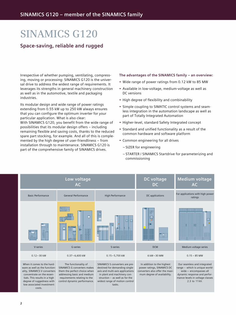
The advantages of the SINAMICS family – an overview:
• Wide range of power ratings from 0.12 kW to 85 MW
• Available in low-voltage, medium-voltage as well as DC versions
• High degree of flexibility and combinability
• Simple coupling to SIMATIC control systems and seam-less integration in the automation landscape as well as part of Totally Integrated Automation
• Higher-level, standard Safety Integrated concept
• Standard and unified functionality as a result of the common hardware and software platform
• Common engineering for all drives
– SIZER for engineering
– STARTER / SINAMICS Startdrive for parameterizing and commissioning
Low voltage AC
DC voltage DC
Medium voltage AC
Basic Performance General Performance High Performance DC applications For applications with high power ratings
V-series G-series S-series DCM Medium voltage series
0.12 – 30 kW 0.37 – 6,600 kW 0.15 – 5,700 kW 6 kW – 30 MW 0.15 – 85 MW
When it comes to the hard-ware as well as the function-ality, SINAMICS V converters
concentrate on the essen-tials. This results in a high degree of ruggedness with low associated investment
costs.
The functionality of SINAMICS G converters makes them the perfect choice when addressing basic and medium requirements relating to the
control dynamic performance.
SINAMICS S converters are pre-destined for demanding single-axis and multi-axis applications
in plant and machinery con-struction – as well as for the
widest range of motion control tasks.
In addition to the highest power ratings, SINAMICS DC
converters also offer the maxi-mum degree of availability.
Our seamless and integrated range – which is unique world-
wide – encompasses all dynamic response and perfor-mance levels in voltage classes
2.3 to 11 kV.
3
SINAMICS G120 – member of the SINAMICS family
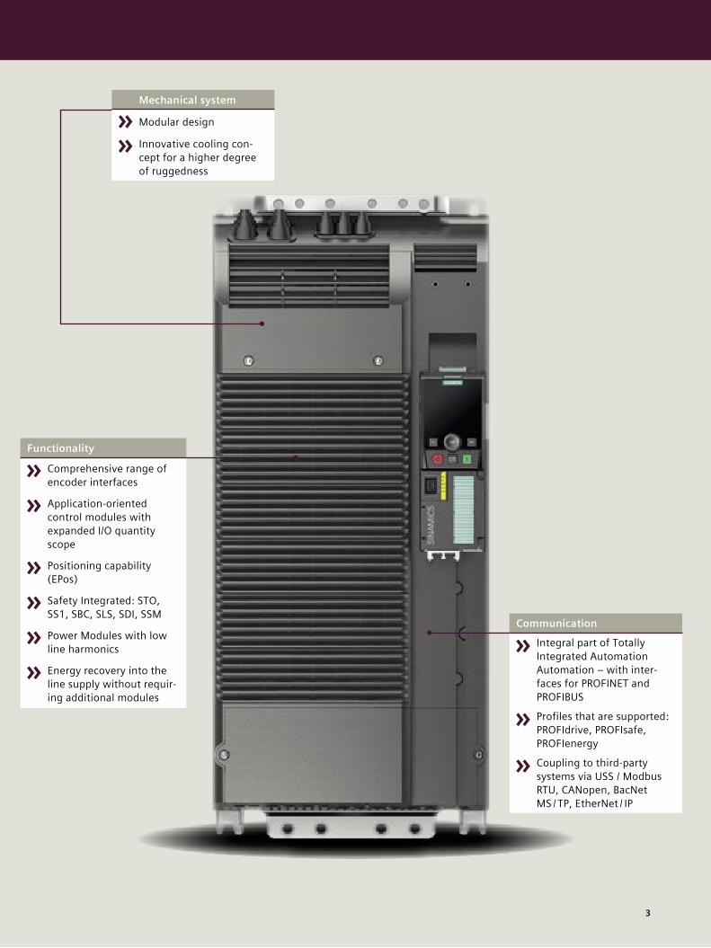
Mechanical system
Modular design
Innovative cooling con-cept for a higher degree of ruggedness
Communication
Integral part of Totally Integrated Automation Automation – with inter-faces for PROFINET and PROFIBUS
Profiles that are supported: PROFIdrive, PROFIsafe, PROFIenergy
Coupling to third-party systems via USS / Modbus RTU, CANopen, BacNet MS / TP, EtherNet / IP
Functionality
Comprehensive range of encoder interfaces
Application-oriented control modules with expanded I/O quantity scope
Positioning capability (EPos)
Safety Integrated: STO, SS1, SBC, SLS, SDI, SSM
Power Modules with low line harmonics
Energy recovery into the line supply without requir-ing additional modules
4
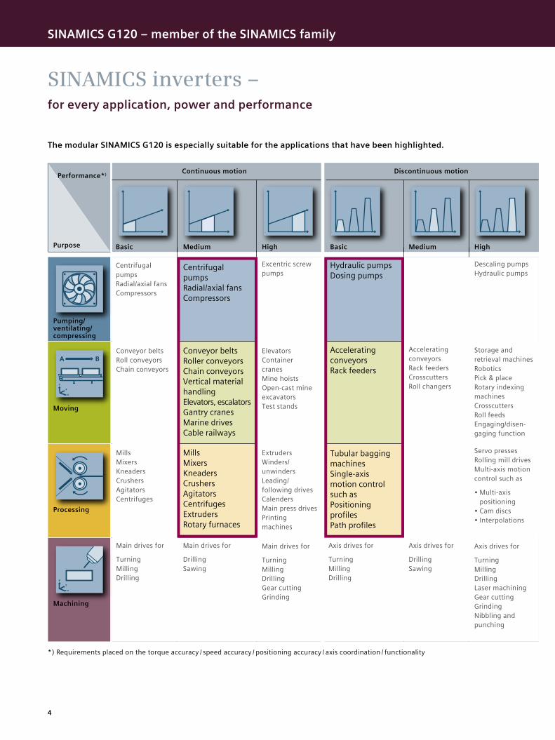
SINAMICS inverters –for every application, power and performance
The modular SINAMICS G120 is especially suitable for the applications that have been highlighted.
Performance*)
Purpose
Continuous motion Discontinuous motion
Pumping/ ventilating/ compressing
Moving
Processing
Machining
Centrifugal pumps Radial/axial fans Compressors
Conveyor belts Roll conveyors Chain conveyors
Mills Mixers Kneaders Crushers Agitators Centrifuges
Main drives for
Turning Milling Drilling
*) Requirements placed on the torque accuracy / speed accuracy / positioning accuracy / axis coordination / functionality
Centrifugal pumps Radial/axial fans Compressors
Conveyor belts Roller conveyors Chain conveyors Vertical material handling Elevators, escalators Gantry cranes Marine drives Cable railways
Mills Mixers Kneaders Crushers Agitators Centrifuges Extruders Rotary furnaces
Main drives for
Drilling Sawing
Excentric screw pumps
Elevators Container cranes Mine hoists Open-cast mine excavators Test stands
Extruders Winders/ unwinders Leading/ following drives Calenders Main press drives Printing machines
Main drives for
Turning Milling Drilling Gear cutting Grinding
Hydraulic pumps Dosing pumps
Accelerating conveyors Rack feeders
Tubular bagging machines Single-axis motion control such as Positioning profiles Path profiles
Axis drives for
Turning Milling Drilling
Accelerating conveyors Rack feeders Crosscutters Roll changers
Storage and retrieval machines Robotics Pick & place Rotary indexing machines Crosscutters Roll feeds Engaging/disen-gaging function
Servo presses Rolling mill drives Multi-axis motion control such as
• Multi-axis positioning
• Cam discs• Interpolations
Axis drives for
Drilling Sawing
Axis drives for
Turning Milling Drilling Laser machining Gear cutting Grinding Nibbling and punching
Descaling pumps Hydraulic pumps
Basic BasicMedium MediumHigh High
SINAMICS G120 – member of the SINAMICS family
5
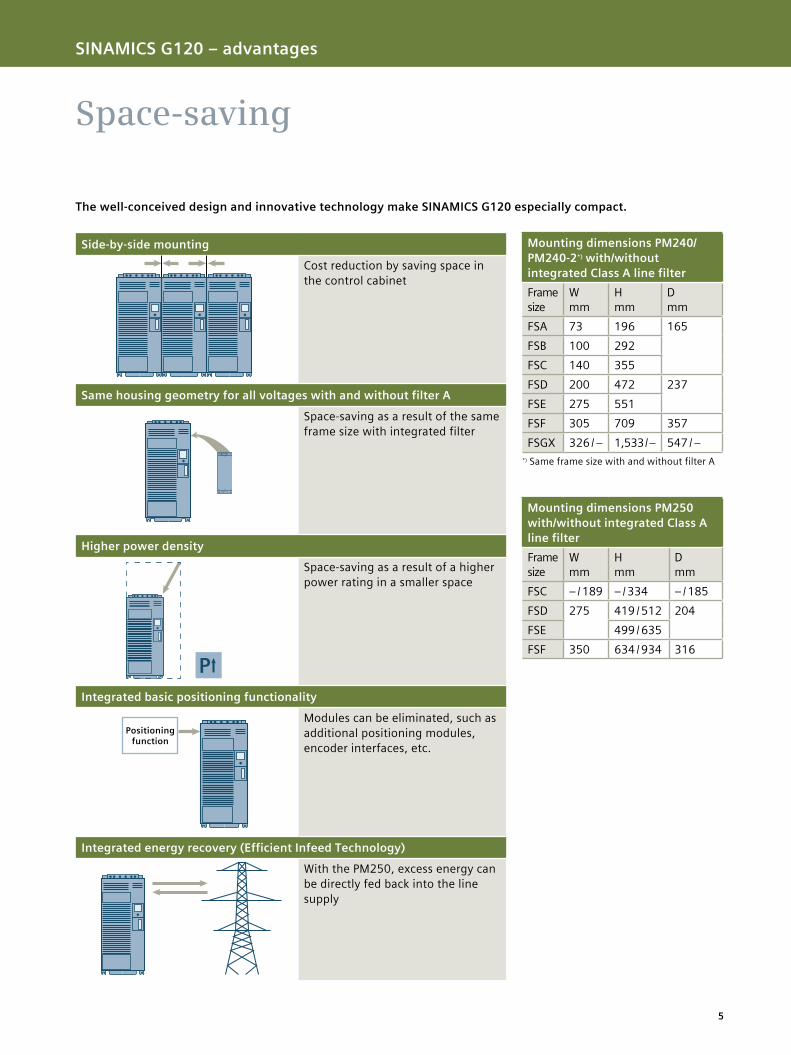
Space-saving
Side-by-side mounting
Cost reduction by saving space in the control cabinet
Same housing geometry for all voltages with and without filter A
Space-saving as a result of the same frame size with integrated filter
Higher power density
Space-saving as a result of a higher power rating in a smaller space
Integrated basic positioning functionality
Modules can be eliminated, such as additional positioning modules, encoder interfaces, etc.
Integrated energy recovery (Efficient Infeed Technology)
With the PM250, excess energy can be directly fed back into the line supply
P
Positioning function
The well-conceived design and innovative technology make SINAMICS G120 especially compact.
SINAMICS G120 – member of the SINAMICS family SINAMICS G120 – advantages
Mounting dimensions PM240/PM240-2*) with/without integrated Class A line filterFrame size
W mm
H mm
D mm
FSA 73 196 165FSB 100 292FSC 140 355FSD 200 472 237FSE 275 551FSF 305 709 357FSGX 326 / – 1,533 / – 547 / –
*) Same frame size with and without filter A
Mounting dimensions PM250 with/without integrated Class A line filterFrame size
W mm
H mm
D mm
FSC – / 189 – / 334 – / 185FSD 275 419 / 512 204FSE 499 / 635FSF 350 634 / 934 316
6
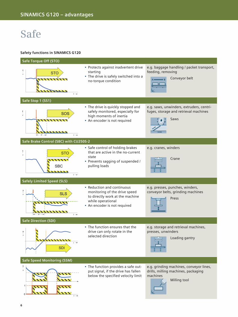
Safe
Safety functions in SINAMICS G120
SINAMICS G120 – advantages
Safe Torque Off (STO)
• Protects against inadvertent drive starting
• The drive is safely switched into a no-torque condition
e.g. baggage handling / packet transport, feeding, removing
Conveyor belt
Safe Stop 1 (SS1)
• The drive is quickly stopped and safely monitored, especially for high moments of inertia
• An encoder is not required
e.g. saws, unwinders, extruders, centri-fuges, storage and retrieval machines
Saws
Safe Brake Control (SBC) with CU250S-2
• Safe control of holding brakes that are active in the no-current state
• Prevents sagging of suspended / pulling loads
e.g. cranes, winders
Crane
Safely Limited Speed (SLS)
• Reduction and continuous monitoring of the drive speed to directly work at the machine while operational
• An encoder is not required
e.g. presses, punches, winders, conveyor belts, grinding machines
Press
Safe Direction (SDI)
• The function ensures that the drive can only rotate in the selected direction
e.g. storage and retrieval machines, presses, unwinders
Loading gantry
Safe Speed Monitoring (SSM)
• The function provides a safe out-put signal, if the drive has fallen below the specified velocity limit
e.g. grinding machines, conveyor lines, drills, milling machines, packaging machines
Milling tool
G_D
211_
XX
_002
10
t
v STO
v
t
STO
SBC
G_D
211_
XX
_002
08
SLS
t
v
∆t
G_P
M21
_XX
_001
16
v
t
SDI
t
G_D
211_
XX
_002
09
v
1
0
7
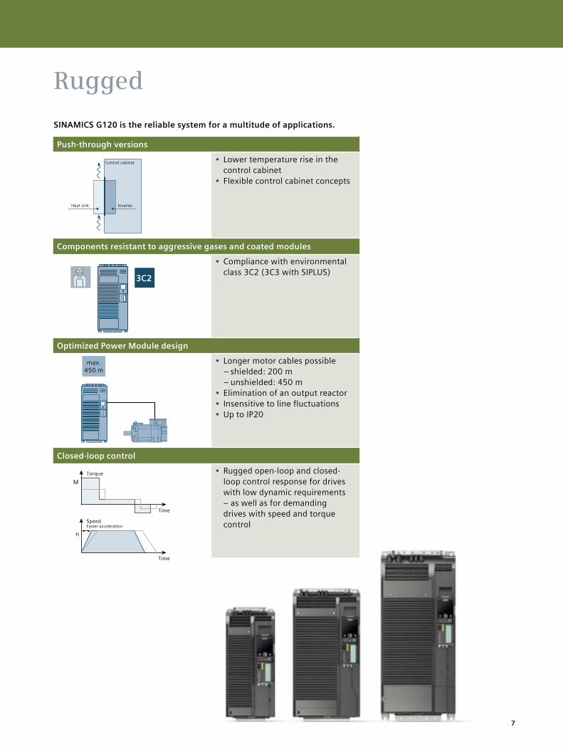
Push-through versions
• Lower temperature rise in the control cabinet
• Flexible control cabinet concepts
Components resistant to aggressive gases and coated modules
• Compliance with environmental class 3C2 (3C3 with SIPLUS)
Optimized Power Module design
• Longer motor cables possible – shielded: 200 m – unshielded: 450 m
• Elimination of an output reactor• Insensitive to line fluctuations • Up to IP20
Closed-loop control
• Rugged open-loop and closed-loop control response for drives with low dynamic requirements – as well as for demanding drives with speed and torque control
3C2
n
M
Rugged
SINAMICS G120 is the reliable system for a multitude of applications.
SINAMICS G120 – advantages
Heat sink
Control cabinet
Inverter
max. 450 m
Torque
Time
Time
SpeedFaster acceleration
8
Integrated, intelligent and innovative
A holistic approach for automation and drive technology paves the way for improved production. With SINAMICS G120, we consequentially implement this concept. Down to the finest details. We can offer you everything that helps you to efficiently work with our innovative inverters. And create the preconditions so that these devices can be seamlessly integrated into the automation environment.
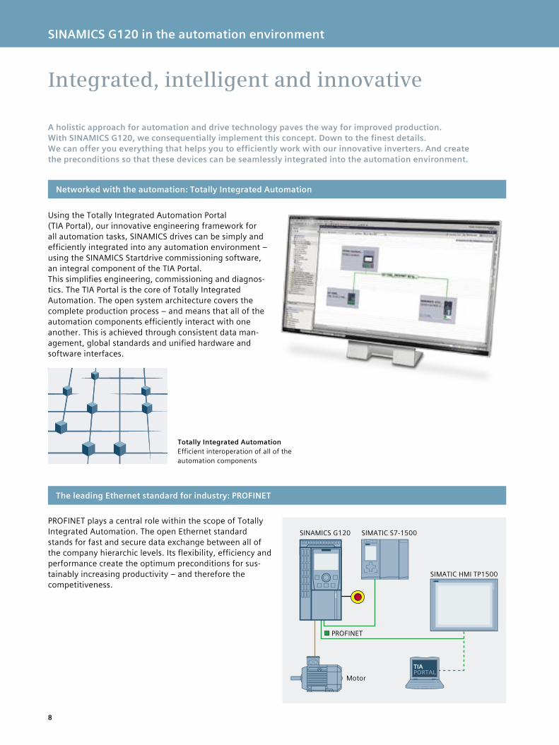
PROFINET plays a central role within the scope of Totally Integrated Automation. The open Ethernet standard stands for fast and secure data exchange between all of the company hierarchic levels. Its flexibility, efficiency and performance create the optimum preconditions for sus-tainably increasing productivity – and therefore the competitiveness.
Networked with the automation: Totally Integrated Automation
The leading Ethernet standard for industry: PROFINET
SINAMICS G120 in the automation environment
Using the Totally Integrated Automation Portal (TIA Portal), our innovative engineering framework for all automation tasks, SINAMICS drives can be simply and efficiently integrated into any automation environment – using the SINAMICS Startdrive commissioning software, an integral component of the TIA Portal. This simplifies engineering, commissioning and diagnos-tics. The TIA Portal is the core of Totally Integrated Automation. The open system architecture covers the complete production process – and means that all of the automation components efficiently interact with one another. This is achieved through consistent data man-agement, global standards and unified hardware and software interfaces.
TIAPORTAL
Motor
SIMATIC HMI TP1500
SIMATIC S7-1500SINAMICS G120
PROFINET
Totally Integrated AutomationEfficient interoperation of all of the automation components
9
PROFINET/PROFIBUSPROFINET/PROFIBUS
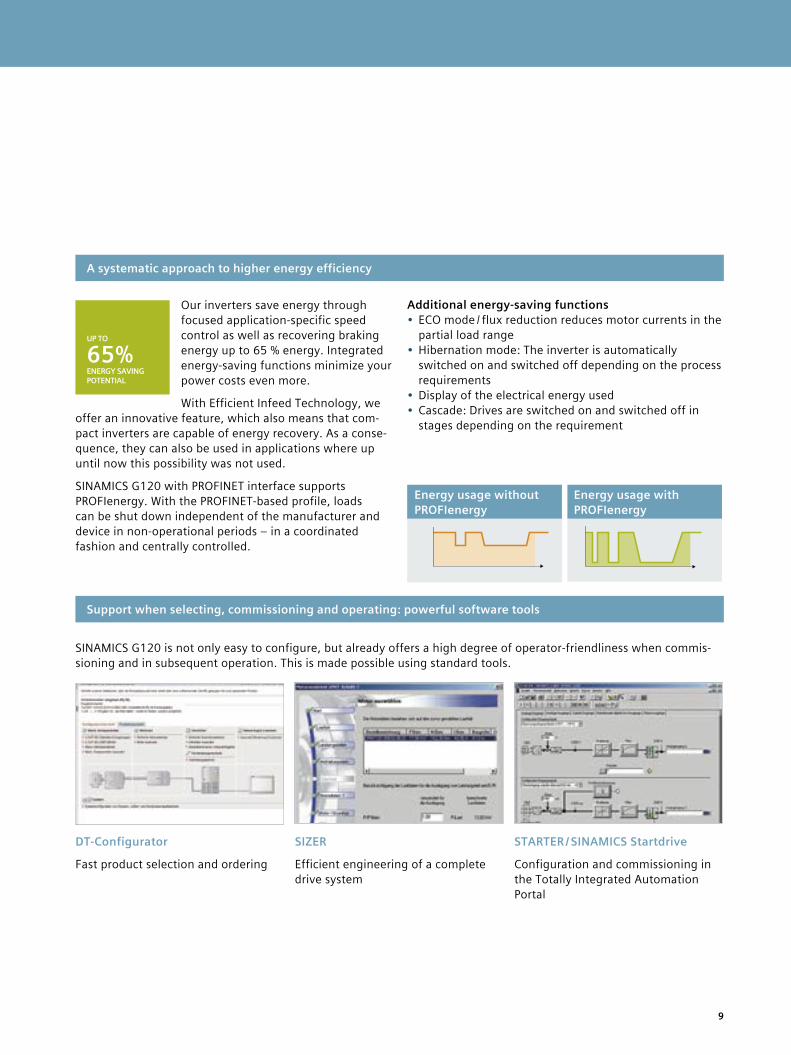
Energy usage without PROFIenergy
Energy usage with PROFIenergy
Our inverters save energy through focused application-specific speed control as well as recovering braking energy up to 65 % energy. Integrated energy-saving functions minimize your power costs even more.
With Efficient Infeed Technology, we offer an innovative feature, which also means that com-pact inverters are capable of energy recovery. As a conse-quence, they can also be used in applications where up until now this possibility was not used.
SINAMICS G120 with PROFINET interface supports PROFIenergy. With the PROFINET-based profile, loads can be shut down independent of the manufacturer and device in non-operational periods – in a coordinated fashion and centrally controlled.
A systematic approach to higher energy efficiency
SINAMICS G120 in the automation environment
Support when selecting, commissioning and operating: powerful software tools
DT-Configurator
Fast product selection and ordering
SIZER
Efficient engineering of a complete drive system
STARTER / SINAMICS Startdrive
Configuration and commissioning in the Totally Integrated Automation Portal
SINAMICS G120 is not only easy to configure, but already offers a high degree of operator-friendliness when commis-sioning and in subsequent operation. This is made possible using standard tools.
UP TO
65%ENERGY SAVING POTENTIAL
Additional energy-saving functions• ECO mode / flux reduction reduces motor currents in the
partial load range• Hibernation mode: The inverter is automatically
switched on and switched off depending on the process requirements
• Display of the electrical energy used• Cascade: Drives are switched on and switched off in
stages depending on the requirement
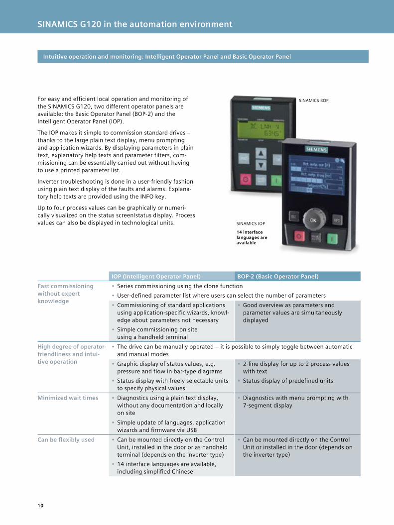
SINAMICS BOP
SINAMICS G120 in the automation environment
10
For easy and efficient local operation and monitoring of the SINAMICS G120, two different operator panels are available: the Basic Operator Panel (BOP-2) and the Intelligent Operator Panel (IOP).
The IOP makes it simple to commission standard drives – thanks to the large plain text display, menu prompting and application wizards. By displaying parameters in plain text, explanatory help texts and parameter filters, com-missioning can be essentially carried out without having to use a printed parameter list.
Inverter troubleshooting is done in a user-friendly fashion using plain text display of the faults and alarms. Explana-tory help texts are provided using the INFO key.
Up to four process values can be graphically or numeri-cally visualized on the status screen/status display. Process values can also be displayed in technological units.
Intuitive operation and monitoring: Intelligent Operator Panel and Basic Operator Panel
IOP (Intelligent Operator Panel) BOP-2 (Basic Operator Panel)Fast commissioning without expert knowledge
• Series commissioning using the clone function• User-defined parameter list where users can select the number of parameters• Commissioning of standard applications
using application-specific wizards, knowl-edge about parameters not necessary
• Simple commissioning on site using a handheld terminal
• Good overview as parameters and parameter values are simultaneously displayed
High degree of operator- friendliness and intui-tive operation
• The drive can be manually operated – it is possible to simply toggle between automatic and manual modes
• Graphic display of status values, e.g. pressure and flow in bar-type diagrams
• Status display with freely selectable units to specify physical values
• 2-line display for up to 2 process values with text
• Status display of predefined units
Minimized wait times • Diagnostics using a plain text display, without any documentation and locally on site
• Diagnostics with menu prompting with 7-segment display
• Simple update of languages, application wizards and firmware via USB
Can be flexibly used • Can be mounted directly on the Control Unit, installed in the door or as handheld terminal (depends on the inverter type)
• 14 interface languages are available, including simplified Chinese
• Can be mounted directly on the Control Unit or installed in the door (depends on the inverter type)
SINAMICS IOP
14 interface languages are available
11
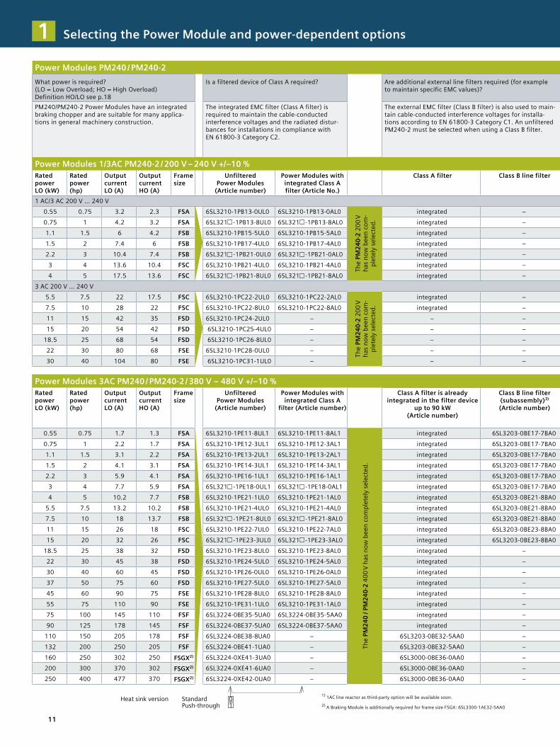
Power Modules PM240 / PM240-2What power is required? (LO = Low Overload; HO = High Overload)Definition HO/LO see p.18
Is a filtered device of Class A required? Are additional external line filters required (for example to maintain specific EMC values)?
Is a braking resistor required as a result of the application?
Should an output filter be used, for instance to be able to use long motor cables?
Is a shield plate required for the Power Module?
PM240/PM240-2 Power Modules have an integrated braking chopper and are suitable for many applica-tions in general machinery construction.
The integrated EMC filter (Class A filter) is required to maintain the cable-conducted interference voltages and the radiated distur-bances for installations in compliance with EN 61800-3 Category C2.
The external EMC filter (Class B filter) is also used to main-tain cable-conducted interference voltages for installa-tions according to EN 61800-3 Category C1. An unfiltered PM240-2 must be selected when using a Class B filter.
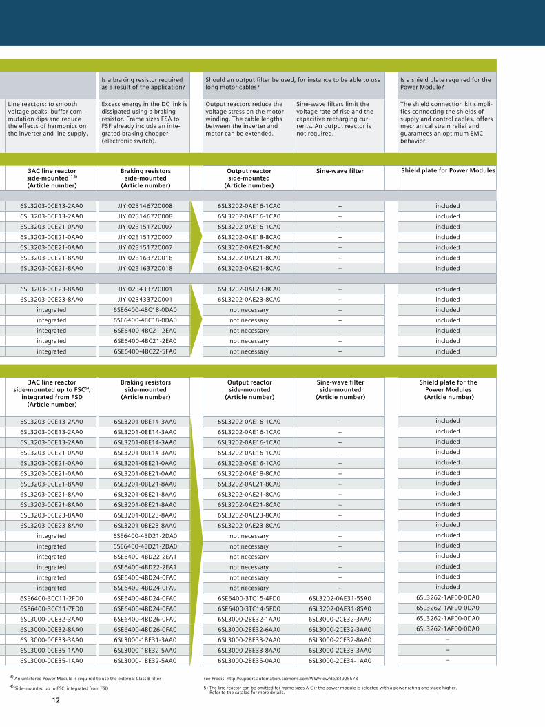
Line reactors: to smooth voltage peaks, buffer com-mutation dips and reduce the effects of harmonics on the inverter and line supply.
Excess energy in the DC link is dissipated using a braking resistor. Frame sizes FSA to FSF already include an inte-grated braking chopper (electronic switch).
Output reactors reduce the voltage stress on the motor winding. The cable lengths between the inverter and motor can be extended.
Sine-wave filters limit the voltage rate of rise and the capacitive recharging cur-rents. An output reactor is not required.
The shield connection kit simpli-fies connecting the shields of supply and control cables, offers mechanical strain relief and guarantees an optimum EMC behavior.
Power Modules 1/3AC PM240-2 / 200 V – 240 V +/–10 %Rated power LO (kW)
Rated power (hp)
Output current LO (A)
Output current HO (A)
Frame size
Unfiltered Power Modules
(Article number)
Power Modules with integrated Class A filter (Article No.)
Class A filter Class B line filter 3AC line reactor side-mounted1) 5) (Article number)
Braking resistors side-mounted
(Article number)
Output reactor side-mounted
(Article number)
Sine-wave filter Shield plate for Power Modules
1 AC/3 AC 200 V … 240 V0.55 0.75 3.2 2.3 FSA 6SL3210-1PB13-0UL0 6SL3210-1PB13-0AL0
The
PM24
0-2
200
V
has n
ow b
een
com
-pl
etel
y se
lect
ed.
integrated – 6SL3203-0CE13-2AA0 JJY:023146720008 6SL3202-0AE16-1CA0 – included0.75 1 4.2 3.2 FSA 6SL321 -1PB13-8UL0 6SL321 -1PB13-8AL0 integrated – 6SL3203-0CE13-2AA0 JJY:023146720008 6SL3202-0AE16-1CA0 – included1.1 1.5 6 4.2 FSB 6SL3210-1PB15-5UL0 6SL3210-1PB15-5AL0 integrated – 6SL3203-0CE21-0AA0 JJY:023151720007 6SL3202-0AE16-1CA0 – included1.5 2 7.4 6 FSB 6SL3210-1PB17-4UL0 6SL3210-1PB17-4AL0 integrated – 6SL3203-0CE21-0AA0 JJY:023151720007 6SL3202-0AE18-8CA0 – included2.2 3 10.4 7.4 FSB 6SL321 -1PB21-0UL0 6SL321 -1PB21-0AL0 integrated – 6SL3203-0CE21-0AA0 JJY:023151720007 6SL3202-0AE21-8CA0 – included3 4 13.6 10.4 FSC 6SL3210-1PB21-4UL0 6SL3210-1PB21-4AL0 integrated – 6SL3203-0CE21-8AA0 JJY:023163720018 6SL3202-0AE21-8CA0 – included4 5 17.5 13.6 FSC 6SL321 -1PB21-8UL0 6SL321 -1PB21-8AL0 integrated – 6SL3203-0CE21-8AA0 JJY:023163720018 6SL3202-0AE21-8CA0 – included
3 AC 200 V … 240 V5.5 7.5 22 17.5 FSC 6SL3210-1PC22-2UL0 6SL3210-1PC22-2AL0
The
PM24
0-2
200
V
has n
ow b
een
com
-pl
etel
y se
lect
ed.
integrated – 6SL3203-0CE23-8AA0 JJY:023433720001 6SL3202-0AE23-8CA0 – included7.5 10 28 22 FSC 6SL3210-1PC22-8UL0 6SL3210-1PC22-8AL0 integrated – 6SL3203-0CE23-8AA0 JJY:023433720001 6SL3202-0AE23-8CA0 – included11 15 42 35 FSD 6SL3210-1PC24-2UL0 – – – integrated 6SE6400-4BC18-0DA0 not necessary – included15 20 54 42 FSD 6SL3210-1PC25-4UL0 – – – integrated 6SE6400-4BC18-0DA0 not necessary – included
18.5 25 68 54 FSD 6SL3210-1PC26-8UL0 – – – integrated 6SE6400-4BC21-2EA0 not necessary – included22 30 80 68 FSE 6SL3210-1PC28-0UL0 – – – integrated 6SE6400-4BC21-2EA0 not necessary – included30 40 104 80 FSE 6SL3210-1PC31-1UL0 – – – integrated 6SE6400-4BC22-5FA0 not necessary – included
Power Modules 3AC PM240 / PM240-2 / 380 V – 480 V +/–10 %Rated power LO (kW)
Rated power (hp)
Output current LO (A)
Output current HO (A)
Frame size
Unfiltered Power Modules
(Article number)
Power Modules with integrated Class A
filter (Article number)
Class A filter is already integrated in the filter device
up to 90 kW (Article number)
Class B line filter (subassembly)3) (Article number)
3AC line reactor side-mounted up to FSC5);
integrated from FSD (Article number)
Braking resistors side-mounted
(Article number)
Output reactor side-mounted
(Article number)
Sine-wave filter side-mounted
(Article number)
Shield plate for the Power Modules
(Article number)
0.55 0.75 1.7 1.3 FSA 6SL3210-1PE11-8UL1 6SL3210-1PE11-8AL1
The
PM24
0 / P
M24
0-2
400
V ha
s now
bee
n co
mpl
etel
y se
lect
ed.
integrated 6SL3203-0BE17-7BA0 6SL3203-0CE13-2AA0 6SL3201-0BE14-3AA0 6SL3202-0AE16-1CA0 – included
0.75 1 2.2 1.7 FSA 6SL3210-1PE12-3UL1 6SL3210-1PE12-3AL1 integrated 6SL3203-0BE17-7BA0 6SL3203-0CE13-2AA0 6SL3201-0BE14-3AA0 6SL3202-0AE16-1CA0 – included
1.1 1.5 3.1 2.2 FSA 6SL3210-1PE13-2UL1 6SL3210-1PE13-2AL1 integrated 6SL3203-0BE17-7BA0 6SL3203-0CE13-2AA0 6SL3201-0BE14-3AA0 6SL3202-0AE16-1CA0 – included
1.5 2 4.1 3.1 FSA 6SL3210-1PE14-3UL1 6SL3210-1PE14-3AL1 integrated 6SL3203-0BE17-7BA0 6SL3203-0CE21-0AA0 6SL3201-0BE14-3AA0 6SL3202-0AE16-1CA0 – included
2.2 3 5.9 4.1 FSA 6SL3210-1PE16-1UL1 6SL3210-1PE16-1AL1 integrated 6SL3203-0BE17-7BA0 6SL3203-0CE21-0AA0 6SL3201-0BE21-0AA0 6SL3202-0AE16-1CA0 – included
3 4 7.7 5.9 FSA 6SL321 -1PE18-0UL1 6SL321 -1PE18-0AL1 integrated 6SL3203-0BE17-7BA0 6SL3203-0CE21-0AA0 6SL3201-0BE21-0AA0 6SL3202-0AE18-8CA0 – included
4 5 10.2 7.7 FSB 6SL3210-1PE21-1UL0 6SL3210-1PE21-1AL0 integrated 6SL3203-0BE21-8BA0 6SL3203-0CE21-8AA0 6SL3201-0BE21-8AA0 6SL3202-0AE21-8CA0 – included
5.5 7.5 13.2 10.2 FSB 6SL3210-1PE21-4UL0 6SL3210-1PE21-4AL0 integrated 6SL3203-0BE21-8BA0 6SL3203-0CE21-8AA0 6SL3201-0BE21-8AA0 6SL3202-0AE21-8CA0 – included
7.5 10 18 13.7 FSB 6SL321 -1PE21-8UL0 6SL321 -1PE21-8AL0 integrated 6SL3203-0BE21-8BA0 6SL3203-0CE21-8AA0 6SL3201-0BE21-8AA0 6SL3202-0AE21-8CA0 – included
11 15 26 18 FSC 6SL3210-1PE22-7UL0 6SL3210-1PE22-7AL0 integrated 6SL3203-0BE23-8BA0 6SL3203-0CE23-8AA0 6SL3201-0BE23-8AA0 6SL3202-0AE23-8CA0 – included
15 20 32 26 FSC 6SL321 -1PE23-3UL0 6SL321 -1PE23-3AL0 integrated 6SL3203-0BE23-8BA0 6SL3203-0CE23-8AA0 6SL3201-0BE23-8AA0 6SL3202-0AE23-8CA0 – included
18.5 25 38 32 FSD 6SL3210-1PE23-8UL0 6SL3210-1PE23-8AL0 integrated – integrated 6SE6400-4BD21-2DA0 not necessary – included
22 30 45 38 FSD 6SL3210-1PE24-5UL0 6SL3210-1PE24-5AL0 integrated – integrated 6SE6400-4BD21-2DA0 not necessary – included
30 40 60 45 FSD 6SL3210-1PE26-0UL0 6SL3210-1PE26-0AL0 integrated – integrated 6SE6400-4BD22-2EA1 not necessary – included
37 50 75 60 FSD 6SL3210-1PE27-5UL0 6SL3210-1PE27-5AL0 integrated – integrated 6SE6400-4BD22-2EA1 not necessary – included
45 60 90 75 FSE 6SL3210-1PE28-8UL0 6SL3210-1PE28-8AL0 integrated – integrated 6SE6400-4BD24-0FA0 not necessary – included
55 75 110 90 FSE 6SL3210-1PE31-1UL0 6SL3210-1PE31-1AL0 integrated – integrated 6SE6400-4BD24-0FA0 not necessary – included
75 100 145 110 FSF 6SL3224-0BE35-5UA0 6SL3224-0BE35-5AA0 integrated – 6SE6400-3CC11-2FD0 6SE6400-4BD24-0FA0 6SE6400-3TC15-4FD0 6SL3202-0AE31-5SA0 6SL3262-1AF00-0DA0
90 125 178 145 FSF 6SL3224-0BE37-5UA0 6SL3224-0BE37-5AA0 integrated – 6SE6400-3CC11-7FD0 6SE6400-4BD24-0FA0 6SE6400-3TC14-5FD0 6SL3202-0AE31-8SA0 6SL3262-1AF00-0DA0
110 150 205 178 FSF 6SL3224-0BE38-8UA0 – 6SL3203-0BE32-5AA0 – 6SL3000-0CE32-3AA0 6SE6400-4BD26-0FA0 6SL3000-2BE32-1AA0 6SL3000-2CE32-3AA0 6SL3262-1AF00-0DA0
132 200 250 205 FSF 6SL3224-0BE41-1UA0 – 6SL3203-0BE32-5AA0 – 6SL3000-0CE32-8AA0 6SE6400-4BD26-0FA0 6SL3000-2BE32-6AA0 6SL3000-2CE32-3AA0 6SL3262-1AF00-0DA0
160 250 302 250 FSGX2) 6SL3224-0XE41-3UA0 – 6SL3000-0BE36-0AA0 – 6SL3000-0CE33-3AA0 6SL3000-1BE31-3AA0 6SL3000-2BE33-2AA0 6SL3000-2CE32-8AA0 –
200 300 370 302 FSGX2) 6SL3224-0XE41-6UA0 – 6SL3000-0BE36-0AA0 – 6SL3000-0CE35-1AA0 6SL3000-1BE32-5AA0 6SL3000-2BE33-8AA0 6SL3000-2CE33-3AA0 –
250 400 477 370 FSGX2) 6SL3224-0XE42-0UA0 – 6SL3000-0BE36-0AA0 – 6SL3000-0CE35-1AA0 6SL3000-1BE32-5AA0 6SL3000-2BE35-0AA0 6SL3000-2CE34-1AA0 –
Selecting the Power Module and power-dependent options1
Heat sink version Standard 0 Push-through 1
1) 1AC line reactor as third-party option will be available soon. 2) A Braking Module is additionally required for frame size FSGX: 6SL3300-1AE32-5AA0
12
Power Modules PM240 / PM240-2What power is required? (LO = Low Overload; HO = High Overload)Definition HO/LO see p.18
Is a filtered device of Class A required? Are additional external line filters required (for example to maintain specific EMC values)?
Is a braking resistor required as a result of the application?
Should an output filter be used, for instance to be able to use long motor cables?
Is a shield plate required for the Power Module?
PM240/PM240-2 Power Modules have an integrated braking chopper and are suitable for many applica-tions in general machinery construction.
The integrated EMC filter (Class A filter) is required to maintain the cable-conducted interference voltages and the radiated distur-bances for installations in compliance with EN 61800-3 Category C2.
The external EMC filter (Class B filter) is also used to main-tain cable-conducted interference voltages for installa-tions according to EN 61800-3 Category C1. An unfiltered PM240-2 must be selected when using a Class B filter.
Line reactors: to smooth voltage peaks, buffer com-mutation dips and reduce the effects of harmonics on the inverter and line supply.
Excess energy in the DC link is dissipated using a braking resistor. Frame sizes FSA to FSF already include an inte-grated braking chopper (electronic switch).
Output reactors reduce the voltage stress on the motor winding. The cable lengths between the inverter and motor can be extended.
Sine-wave filters limit the voltage rate of rise and the capacitive recharging cur-rents. An output reactor is not required.
The shield connection kit simpli-fies connecting the shields of supply and control cables, offers mechanical strain relief and guarantees an optimum EMC behavior.
Power Modules 1/3AC PM240-2 / 200 V – 240 V +/–10 %Rated power LO (kW)
Rated power (hp)
Output current LO (A)
Output current HO (A)
Frame size
Unfiltered Power Modules
(Article number)
Power Modules with integrated Class A filter (Article No.)
Class A filter Class B line filter 3AC line reactor side-mounted1) 5) (Article number)
Braking resistors side-mounted
(Article number)
Output reactor side-mounted
(Article number)
Sine-wave filter Shield plate for Power Modules
1 AC/3 AC 200 V … 240 V0.55 0.75 3.2 2.3 FSA 6SL3210-1PB13-0UL0 6SL3210-1PB13-0AL0
The
PM24
0-2
200
V
has n
ow b
een
com
-pl
etel
y se
lect
ed.
integrated – 6SL3203-0CE13-2AA0 JJY:023146720008 6SL3202-0AE16-1CA0 – included0.75 1 4.2 3.2 FSA 6SL321 -1PB13-8UL0 6SL321 -1PB13-8AL0 integrated – 6SL3203-0CE13-2AA0 JJY:023146720008 6SL3202-0AE16-1CA0 – included1.1 1.5 6 4.2 FSB 6SL3210-1PB15-5UL0 6SL3210-1PB15-5AL0 integrated – 6SL3203-0CE21-0AA0 JJY:023151720007 6SL3202-0AE16-1CA0 – included1.5 2 7.4 6 FSB 6SL3210-1PB17-4UL0 6SL3210-1PB17-4AL0 integrated – 6SL3203-0CE21-0AA0 JJY:023151720007 6SL3202-0AE18-8CA0 – included2.2 3 10.4 7.4 FSB 6SL321 -1PB21-0UL0 6SL321 -1PB21-0AL0 integrated – 6SL3203-0CE21-0AA0 JJY:023151720007 6SL3202-0AE21-8CA0 – included3 4 13.6 10.4 FSC 6SL3210-1PB21-4UL0 6SL3210-1PB21-4AL0 integrated – 6SL3203-0CE21-8AA0 JJY:023163720018 6SL3202-0AE21-8CA0 – included4 5 17.5 13.6 FSC 6SL321 -1PB21-8UL0 6SL321 -1PB21-8AL0 integrated – 6SL3203-0CE21-8AA0 JJY:023163720018 6SL3202-0AE21-8CA0 – included
3 AC 200 V … 240 V5.5 7.5 22 17.5 FSC 6SL3210-1PC22-2UL0 6SL3210-1PC22-2AL0
The
PM24
0-2
200
V
has n
ow b
een
com
-pl
etel
y se
lect
ed.
integrated – 6SL3203-0CE23-8AA0 JJY:023433720001 6SL3202-0AE23-8CA0 – included7.5 10 28 22 FSC 6SL3210-1PC22-8UL0 6SL3210-1PC22-8AL0 integrated – 6SL3203-0CE23-8AA0 JJY:023433720001 6SL3202-0AE23-8CA0 – included11 15 42 35 FSD 6SL3210-1PC24-2UL0 – – – integrated 6SE6400-4BC18-0DA0 not necessary – included15 20 54 42 FSD 6SL3210-1PC25-4UL0 – – – integrated 6SE6400-4BC18-0DA0 not necessary – included
18.5 25 68 54 FSD 6SL3210-1PC26-8UL0 – – – integrated 6SE6400-4BC21-2EA0 not necessary – included22 30 80 68 FSE 6SL3210-1PC28-0UL0 – – – integrated 6SE6400-4BC21-2EA0 not necessary – included30 40 104 80 FSE 6SL3210-1PC31-1UL0 – – – integrated 6SE6400-4BC22-5FA0 not necessary – included
Power Modules 3AC PM240 / PM240-2 / 380 V – 480 V +/–10 %Rated power LO (kW)
Rated power (hp)
Output current LO (A)
Output current HO (A)
Frame size
Unfiltered Power Modules
(Article number)
Power Modules with integrated Class A
filter (Article number)
Class A filter is already integrated in the filter device
up to 90 kW (Article number)
Class B line filter (subassembly)3) (Article number)
3AC line reactor side-mounted up to FSC5);
integrated from FSD (Article number)
Braking resistors side-mounted
(Article number)
Output reactor side-mounted
(Article number)
Sine-wave filter side-mounted
(Article number)
Shield plate for the Power Modules
(Article number)
0.55 0.75 1.7 1.3 FSA 6SL3210-1PE11-8UL1 6SL3210-1PE11-8AL1
The
PM24
0 / P
M24
0-2
400
V ha
s now
bee
n co
mpl
etel
y se
lect
ed.
integrated 6SL3203-0BE17-7BA0 6SL3203-0CE13-2AA0 6SL3201-0BE14-3AA0 6SL3202-0AE16-1CA0 – included
0.75 1 2.2 1.7 FSA 6SL3210-1PE12-3UL1 6SL3210-1PE12-3AL1 integrated 6SL3203-0BE17-7BA0 6SL3203-0CE13-2AA0 6SL3201-0BE14-3AA0 6SL3202-0AE16-1CA0 – included
1.1 1.5 3.1 2.2 FSA 6SL3210-1PE13-2UL1 6SL3210-1PE13-2AL1 integrated 6SL3203-0BE17-7BA0 6SL3203-0CE13-2AA0 6SL3201-0BE14-3AA0 6SL3202-0AE16-1CA0 – included
1.5 2 4.1 3.1 FSA 6SL3210-1PE14-3UL1 6SL3210-1PE14-3AL1 integrated 6SL3203-0BE17-7BA0 6SL3203-0CE21-0AA0 6SL3201-0BE14-3AA0 6SL3202-0AE16-1CA0 – included
2.2 3 5.9 4.1 FSA 6SL3210-1PE16-1UL1 6SL3210-1PE16-1AL1 integrated 6SL3203-0BE17-7BA0 6SL3203-0CE21-0AA0 6SL3201-0BE21-0AA0 6SL3202-0AE16-1CA0 – included
3 4 7.7 5.9 FSA 6SL321 -1PE18-0UL1 6SL321 -1PE18-0AL1 integrated 6SL3203-0BE17-7BA0 6SL3203-0CE21-0AA0 6SL3201-0BE21-0AA0 6SL3202-0AE18-8CA0 – included
4 5 10.2 7.7 FSB 6SL3210-1PE21-1UL0 6SL3210-1PE21-1AL0 integrated 6SL3203-0BE21-8BA0 6SL3203-0CE21-8AA0 6SL3201-0BE21-8AA0 6SL3202-0AE21-8CA0 – included
5.5 7.5 13.2 10.2 FSB 6SL3210-1PE21-4UL0 6SL3210-1PE21-4AL0 integrated 6SL3203-0BE21-8BA0 6SL3203-0CE21-8AA0 6SL3201-0BE21-8AA0 6SL3202-0AE21-8CA0 – included
7.5 10 18 13.7 FSB 6SL321 -1PE21-8UL0 6SL321 -1PE21-8AL0 integrated 6SL3203-0BE21-8BA0 6SL3203-0CE21-8AA0 6SL3201-0BE21-8AA0 6SL3202-0AE21-8CA0 – included
11 15 26 18 FSC 6SL3210-1PE22-7UL0 6SL3210-1PE22-7AL0 integrated 6SL3203-0BE23-8BA0 6SL3203-0CE23-8AA0 6SL3201-0BE23-8AA0 6SL3202-0AE23-8CA0 – included
15 20 32 26 FSC 6SL321 -1PE23-3UL0 6SL321 -1PE23-3AL0 integrated 6SL3203-0BE23-8BA0 6SL3203-0CE23-8AA0 6SL3201-0BE23-8AA0 6SL3202-0AE23-8CA0 – included
18.5 25 38 32 FSD 6SL3210-1PE23-8UL0 6SL3210-1PE23-8AL0 integrated – integrated 6SE6400-4BD21-2DA0 not necessary – included
22 30 45 38 FSD 6SL3210-1PE24-5UL0 6SL3210-1PE24-5AL0 integrated – integrated 6SE6400-4BD21-2DA0 not necessary – included
30 40 60 45 FSD 6SL3210-1PE26-0UL0 6SL3210-1PE26-0AL0 integrated – integrated 6SE6400-4BD22-2EA1 not necessary – included
37 50 75 60 FSD 6SL3210-1PE27-5UL0 6SL3210-1PE27-5AL0 integrated – integrated 6SE6400-4BD22-2EA1 not necessary – included
45 60 90 75 FSE 6SL3210-1PE28-8UL0 6SL3210-1PE28-8AL0 integrated – integrated 6SE6400-4BD24-0FA0 not necessary – included
55 75 110 90 FSE 6SL3210-1PE31-1UL0 6SL3210-1PE31-1AL0 integrated – integrated 6SE6400-4BD24-0FA0 not necessary – included
75 100 145 110 FSF 6SL3224-0BE35-5UA0 6SL3224-0BE35-5AA0 integrated – 6SE6400-3CC11-2FD0 6SE6400-4BD24-0FA0 6SE6400-3TC15-4FD0 6SL3202-0AE31-5SA0 6SL3262-1AF00-0DA0
90 125 178 145 FSF 6SL3224-0BE37-5UA0 6SL3224-0BE37-5AA0 integrated – 6SE6400-3CC11-7FD0 6SE6400-4BD24-0FA0 6SE6400-3TC14-5FD0 6SL3202-0AE31-8SA0 6SL3262-1AF00-0DA0
110 150 205 178 FSF 6SL3224-0BE38-8UA0 – 6SL3203-0BE32-5AA0 – 6SL3000-0CE32-3AA0 6SE6400-4BD26-0FA0 6SL3000-2BE32-1AA0 6SL3000-2CE32-3AA0 6SL3262-1AF00-0DA0
132 200 250 205 FSF 6SL3224-0BE41-1UA0 – 6SL3203-0BE32-5AA0 – 6SL3000-0CE32-8AA0 6SE6400-4BD26-0FA0 6SL3000-2BE32-6AA0 6SL3000-2CE32-3AA0 6SL3262-1AF00-0DA0
160 250 302 250 FSGX2) 6SL3224-0XE41-3UA0 – 6SL3000-0BE36-0AA0 – 6SL3000-0CE33-3AA0 6SL3000-1BE31-3AA0 6SL3000-2BE33-2AA0 6SL3000-2CE32-8AA0 –
200 300 370 302 FSGX2) 6SL3224-0XE41-6UA0 – 6SL3000-0BE36-0AA0 – 6SL3000-0CE35-1AA0 6SL3000-1BE32-5AA0 6SL3000-2BE33-8AA0 6SL3000-2CE33-3AA0 –
250 400 477 370 FSGX2) 6SL3224-0XE42-0UA0 – 6SL3000-0BE36-0AA0 – 6SL3000-0CE35-1AA0 6SL3000-1BE32-5AA0 6SL3000-2BE35-0AA0 6SL3000-2CE34-1AA0 –
Selecting the Power Module and power-dependent options
see Prodis: http://support.automation.siemens.com/WW/view/de/84925578 5) The line reactor can be omitted for frame sizes A-C if the power module is selected with a power rating one stage higher. Refer to the catalog for more details.
3) An unfiltered Power Module is required to use the external Class B filter4) Side-mounted up to FSC; integrated from FSD
13
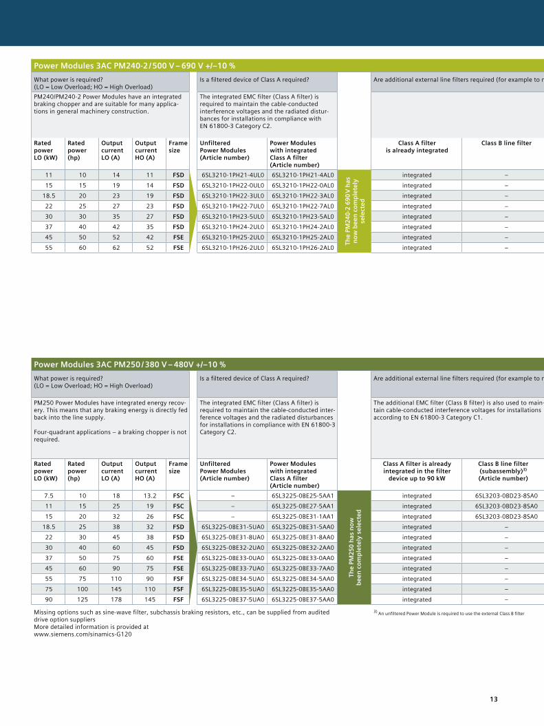
Power Modules 3AC PM240-2 / 500 V – 690 V +/–10 %What power is required? (LO = Low Overload; HO = High Overload)
Is a filtered device of Class A required? Are additional external line filters required (for example to maintain specific EMC values)? Is a braking resistor required as a result of the application?
Should an output filter be used, for example, in order to be able to use longer motor cables?
Is a shield plate required for the Power Module?
PM240/PM240-2 Power Modules have an integrated braking chopper and are suitable for many applica-tions in general machinery construction.
The integrated EMC filter (Class A filter) is required to maintain the cable-conducted interference voltages and the radiated distur-bances for installations in compliance with EN 61800-3 Category C2.
Line reactors: to smooth voltage peaks, buffer com-mutation dips and reduce the effects of harmonics on the inverter and line supply.
Excess energy in the DC link is dissipated using a braking resistor. Frame sizes FSA to FSF already include an inte-grated braking chopper (electronic switch).
Output reactors reduce the voltage stress on the motor winding. The cable lengths between the inverter and motor can be extended.
Sine-wave filters limit the voltage rate of rise and the capacitive recharging cur-rents. An output reactor is not required.
The shield connection kit simpli-fies connecting the shields of supply and control cables, offers mechanical strain relief and guar-antees an optimum EMC behavior.
Rated power LO (kW)
Rated power (hp)
Output current LO (A)
Output current HO (A)
Frame size
Unfiltered Power Modules (Article number)
Power Modules with integrated Class A filter (Article number)
Class A filter is already integrated
Class B line filter Line reactor Braking resistors Output reactor Sine-wave filter (Article number)
Shield plate for Power Modules
11 10 14 11 FSD 6SL3210-1PH21-4UL0 6SL3210-1PH21-4AL0
The
PM24
0-2
690
V ha
s no
w b
een
com
plet
ely
se
lect
ed
integrated – integrated – not necessary – included15 15 19 14 FSD 6SL3210-1PH22-0UL0 6SL3210-1PH22-0AL0 integrated – integrated – not necessary – included
18.5 20 23 19 FSD 6SL3210-1PH22-3UL0 6SL3210-1PH22-3AL0 integrated – integrated – not necessary – included22 25 27 23 FSD 6SL3210-1PH22-7UL0 6SL3210-1PH22-7AL0 integrated – integrated – not necessary – included30 30 35 27 FSD 6SL3210-1PH23-5UL0 6SL3210-1PH23-5AL0 integrated – integrated – not necessary – included37 40 42 35 FSD 6SL3210-1PH24-2UL0 6SL3210-1PH24-2AL0 integrated – integrated – not necessary – included45 50 52 42 FSE 6SL3210-1PH25-2UL0 6SL3210-1PH25-2AL0 integrated – integrated – not necessary – included55 60 62 52 FSE 6SL3210-1PH26-2UL0 6SL3210-1PH26-2AL0 integrated – integrated – not necessary – included
Power Modules 3AC PM250 / 380 V – 480V +/–10 %What power is required? (LO = Low Overload; HO = High Overload)
Is a filtered device of Class A required? Are additional external line filters required (for example to maintain specific EMC values)? Is a braking resistor required as a result of the application?
Should an output filter be used, for example, in order to be able to use longer motor cables?
Is a shield plate required for the Power Module?
PM250 Power Modules have integrated energy recov-ery. This means that any braking energy is directly fed back into the line supply. Four-quadrant applications – a braking chopper is not required.
The integrated EMC filter (Class A filter) is required to maintain the cable-conducted inter-ference voltages and the radiated disturbances for installations in compliance with EN 61800-3 Category C2.
The additional EMC filter (Class B filter) is also used to main-tain cable-conducted interference voltages for installations according to EN 61800-3 Category C1.
In conjunction with the PM250, a line reactor is not required, and it is also not permissible that one is used.
The PM250 is capable of energy recovery. A braking resistor is not used, and it is also not permissible that one is used.
Output reactors reduce the voltage stress on the motor winding. The cable lengths between the inverter and motor can be extended.
Sine-wave filters limit the voltage rate of rise and the capacitive recharging cur-rents. An output reactor is not required.
The shield connection kit simpli-fies connecting the shields of supply and control cables, offers mechanical strain relief and guarantees an optimum EMC behavior.
Rated power LO (kW)
Rated power (hp)
Output current LO (A)
Output current HO (A)
Frame size
Unfiltered Power Modules (Article number)
Power Modules with integrated Class A filter (Article number)
Class A filter is already integrated in the filter
device up to 90 kW
Class B line filter (subassembly)3) (Article number)
Line reactor, side mounting up to FSC;
subchassis from FSD
PM250 with energy recov-ery. As a consequence, it is not permissible that a brak-
ing resistor is used.
Subchassis output reactor (Article number)
Sine-wave filter FSC subchassis, from FSD,
side-mounted (Article number)
Shield plate for Power Modules
(Article number)
7.5 10 18 13.2 FSC – 6SL3225-0BE25-5AA1
The
PM25
0 ha
s no
w
been
com
plet
ely
sele
cted
integrated 6SL3203-0BD23-8SA0 – is not required 6SL3202-0AJ23-2CA0 6SL3202-0AE22-0SA0 6SL3262-1AC00-0DA011 15 25 19 FSC – 6SL3225-0BE27-5AA1 integrated 6SL3203-0BD23-8SA0 – is not required 6SL3202-0AJ23-2CA0 6SL3202-0AE23-3SA0 6SL3262-1AC00-0DA015 20 32 26 FSC – 6SL3225-0BE31-1AA1 integrated 6SL3203-0BD23-8SA0 – is not required 6SL3202-0AJ23-2CA0 6SL3202-0AE23-3SA0 6SL3262-1AC00-0DA0
18.5 25 38 32 FSD 6SL3225-0BE31-5UA0 6SL3225-0BE31-5AA0 integrated – – is not required 6SE6400-3TC05-4DD0 6SL3202-0AE24-6SA0 6SL3262-1AD00-0DA022 30 45 38 FSD 6SL3225-0BE31-8UA0 6SL3225-0BE31-8AA0 integrated – – is not required 6SE6400-3TC03-8DD0 6SL3202-0AE24-6SA0 6SL3262-1AD00-0DA030 40 60 45 FSD 6SL3225-0BE32-2UA0 6SL3225-0BE32-2AA0 integrated – – is not required 6SE6400-3TC05-4DD0 6SL3202-0AE26-2SA0 6SL3262-1AD00-0DA037 50 75 60 FSE 6SL3225-0BE33-0UA0 6SL3225-0BE33-0AA0 integrated – – is not required 6SE6400-3TC08-0ED0 6SL3202-0AE28-8SA0 6SL3262-1AD00-0DA045 60 90 75 FSE 6SL3225-0BE33-7UA0 6SL3225-0BE33-7AA0 integrated – – is not required 6SE6400-3TC07-5ED0 6SL3202-0AE28-8SA0 6SL3262-1AD00-0DA055 75 110 90 FSF 6SL3225-0BE34-5UA0 6SL3225-0BE34-5AA0 integrated – – is not required 6SE6400-3TC14-5FD0 6SL3202-0AE31-5SA0 6SL3262-1AF00-0DA075 100 145 110 FSF 6SL3225-0BE35-5UA0 6SL3225-0BE35-5AA0 integrated – – is not required 6SE6400-3TC15-4FD0 6SL3202-0AE31-5SA0 6SL3262-1AF00-0DA090 125 178 145 FSF 6SL3225-0BE37-5UA0 6SL3225-0BE37-5AA0 integrated – – is not required 6SE6400-3TC14-5FD0 6SL3202-0AE31-8SA0 6SL3262-1AF00-0DA0
Missing options such as sine-wave filter, subchassis braking resistors, etc., can be supplied from audited drive option suppliers More detailed information is provided at www.siemens.com/sinamics-G120
3) An unfiltered Power Module is required to use the external Class B filter
14
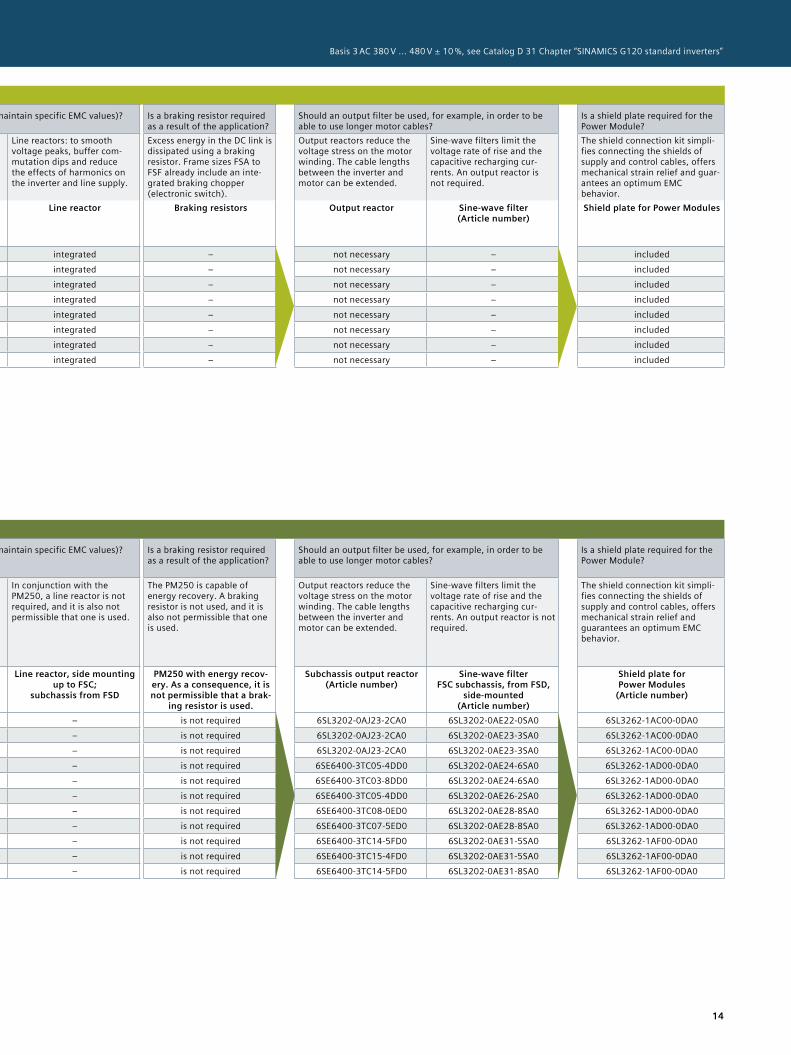
Basis 3 AC 380 V ... 480 V ± 10 %, see Catalog D 31 Chapter “SINAMICS G120 standard inverters”
Power Modules 3AC PM240-2 / 500 V – 690 V +/–10 %What power is required? (LO = Low Overload; HO = High Overload)
Is a filtered device of Class A required? Are additional external line filters required (for example to maintain specific EMC values)? Is a braking resistor required as a result of the application?
Should an output filter be used, for example, in order to be able to use longer motor cables?
Is a shield plate required for the Power Module?
PM240/PM240-2 Power Modules have an integrated braking chopper and are suitable for many applica-tions in general machinery construction.
The integrated EMC filter (Class A filter) is required to maintain the cable-conducted interference voltages and the radiated distur-bances for installations in compliance with EN 61800-3 Category C2.
Line reactors: to smooth voltage peaks, buffer com-mutation dips and reduce the effects of harmonics on the inverter and line supply.
Excess energy in the DC link is dissipated using a braking resistor. Frame sizes FSA to FSF already include an inte-grated braking chopper (electronic switch).
Output reactors reduce the voltage stress on the motor winding. The cable lengths between the inverter and motor can be extended.
Sine-wave filters limit the voltage rate of rise and the capacitive recharging cur-rents. An output reactor is not required.
The shield connection kit simpli-fies connecting the shields of supply and control cables, offers mechanical strain relief and guar-antees an optimum EMC behavior.
Rated power LO (kW)
Rated power (hp)
Output current LO (A)
Output current HO (A)
Frame size
Unfiltered Power Modules (Article number)
Power Modules with integrated Class A filter (Article number)
Class A filter is already integrated
Class B line filter Line reactor Braking resistors Output reactor Sine-wave filter (Article number)
Shield plate for Power Modules
11 10 14 11 FSD 6SL3210-1PH21-4UL0 6SL3210-1PH21-4AL0
The
PM24
0-2
690
V ha
s no
w b
een
com
plet
ely
se
lect
ed
integrated – integrated – not necessary – included15 15 19 14 FSD 6SL3210-1PH22-0UL0 6SL3210-1PH22-0AL0 integrated – integrated – not necessary – included
18.5 20 23 19 FSD 6SL3210-1PH22-3UL0 6SL3210-1PH22-3AL0 integrated – integrated – not necessary – included22 25 27 23 FSD 6SL3210-1PH22-7UL0 6SL3210-1PH22-7AL0 integrated – integrated – not necessary – included30 30 35 27 FSD 6SL3210-1PH23-5UL0 6SL3210-1PH23-5AL0 integrated – integrated – not necessary – included37 40 42 35 FSD 6SL3210-1PH24-2UL0 6SL3210-1PH24-2AL0 integrated – integrated – not necessary – included45 50 52 42 FSE 6SL3210-1PH25-2UL0 6SL3210-1PH25-2AL0 integrated – integrated – not necessary – included55 60 62 52 FSE 6SL3210-1PH26-2UL0 6SL3210-1PH26-2AL0 integrated – integrated – not necessary – included
Power Modules 3AC PM250 / 380 V – 480V +/–10 %What power is required? (LO = Low Overload; HO = High Overload)
Is a filtered device of Class A required? Are additional external line filters required (for example to maintain specific EMC values)? Is a braking resistor required as a result of the application?
Should an output filter be used, for example, in order to be able to use longer motor cables?
Is a shield plate required for the Power Module?
PM250 Power Modules have integrated energy recov-ery. This means that any braking energy is directly fed back into the line supply. Four-quadrant applications – a braking chopper is not required.
The integrated EMC filter (Class A filter) is required to maintain the cable-conducted inter-ference voltages and the radiated disturbances for installations in compliance with EN 61800-3 Category C2.
The additional EMC filter (Class B filter) is also used to main-tain cable-conducted interference voltages for installations according to EN 61800-3 Category C1.
In conjunction with the PM250, a line reactor is not required, and it is also not permissible that one is used.
The PM250 is capable of energy recovery. A braking resistor is not used, and it is also not permissible that one is used.
Output reactors reduce the voltage stress on the motor winding. The cable lengths between the inverter and motor can be extended.
Sine-wave filters limit the voltage rate of rise and the capacitive recharging cur-rents. An output reactor is not required.
The shield connection kit simpli-fies connecting the shields of supply and control cables, offers mechanical strain relief and guarantees an optimum EMC behavior.
Rated power LO (kW)
Rated power (hp)
Output current LO (A)
Output current HO (A)
Frame size
Unfiltered Power Modules (Article number)
Power Modules with integrated Class A filter (Article number)
Class A filter is already integrated in the filter
device up to 90 kW
Class B line filter (subassembly)3) (Article number)
Line reactor, side mounting up to FSC;
subchassis from FSD
PM250 with energy recov-ery. As a consequence, it is not permissible that a brak-
ing resistor is used.
Subchassis output reactor (Article number)
Sine-wave filter FSC subchassis, from FSD,
side-mounted (Article number)
Shield plate for Power Modules
(Article number)
7.5 10 18 13.2 FSC – 6SL3225-0BE25-5AA1
The
PM25
0 ha
s no
w
been
com
plet
ely
sele
cted
integrated 6SL3203-0BD23-8SA0 – is not required 6SL3202-0AJ23-2CA0 6SL3202-0AE22-0SA0 6SL3262-1AC00-0DA011 15 25 19 FSC – 6SL3225-0BE27-5AA1 integrated 6SL3203-0BD23-8SA0 – is not required 6SL3202-0AJ23-2CA0 6SL3202-0AE23-3SA0 6SL3262-1AC00-0DA015 20 32 26 FSC – 6SL3225-0BE31-1AA1 integrated 6SL3203-0BD23-8SA0 – is not required 6SL3202-0AJ23-2CA0 6SL3202-0AE23-3SA0 6SL3262-1AC00-0DA0
18.5 25 38 32 FSD 6SL3225-0BE31-5UA0 6SL3225-0BE31-5AA0 integrated – – is not required 6SE6400-3TC05-4DD0 6SL3202-0AE24-6SA0 6SL3262-1AD00-0DA022 30 45 38 FSD 6SL3225-0BE31-8UA0 6SL3225-0BE31-8AA0 integrated – – is not required 6SE6400-3TC03-8DD0 6SL3202-0AE24-6SA0 6SL3262-1AD00-0DA030 40 60 45 FSD 6SL3225-0BE32-2UA0 6SL3225-0BE32-2AA0 integrated – – is not required 6SE6400-3TC05-4DD0 6SL3202-0AE26-2SA0 6SL3262-1AD00-0DA037 50 75 60 FSE 6SL3225-0BE33-0UA0 6SL3225-0BE33-0AA0 integrated – – is not required 6SE6400-3TC08-0ED0 6SL3202-0AE28-8SA0 6SL3262-1AD00-0DA045 60 90 75 FSE 6SL3225-0BE33-7UA0 6SL3225-0BE33-7AA0 integrated – – is not required 6SE6400-3TC07-5ED0 6SL3202-0AE28-8SA0 6SL3262-1AD00-0DA055 75 110 90 FSF 6SL3225-0BE34-5UA0 6SL3225-0BE34-5AA0 integrated – – is not required 6SE6400-3TC14-5FD0 6SL3202-0AE31-5SA0 6SL3262-1AF00-0DA075 100 145 110 FSF 6SL3225-0BE35-5UA0 6SL3225-0BE35-5AA0 integrated – – is not required 6SE6400-3TC15-4FD0 6SL3202-0AE31-5SA0 6SL3262-1AF00-0DA090 125 178 145 FSF 6SL3225-0BE37-5UA0 6SL3225-0BE37-5AA0 integrated – – is not required 6SE6400-3TC14-5FD0 6SL3202-0AE31-8SA0 6SL3262-1AF00-0DA0
Missing options such as sine-wave filter, subchassis braking resistors, etc., can be supplied from audited drive option suppliers More detailed information is provided at www.siemens.com/sinamics-G120
3) An unfiltered Power Module is required to use the external Class B filter
15Detailed information on products and options is provided in the current Catalog D 31 in Chapter “SINAMICS G120 standard inverters” or in the Siemens Industry Mall.
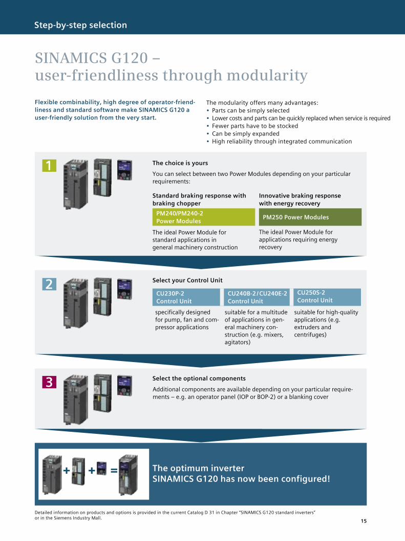
Flexible combinability, high degree of operator-friend- liness and standard software make SINAMICS G120 a user-friendly solution from the very start.
SINAMICS G120 – user-friendliness through modularity
Step-by-step selection
The modularity offers many advantages:• Parts can be simply selected• Lower costs and parts can be quickly replaced when service is required• Fewer parts have to be stocked• Can be simply expanded• High reliability through integrated communication
The optimum inverter SINAMICS G120 has now been configured!
Select the optional components3Additional components are available depending on your particular require-ments – e.g. an operator panel (IOP or BOP-2) or a blanking cover
Select your Control Unit2CU230P-2 Control Unit
CU240B-2 / CU240E-2 Control Unit
CU250S-2 Control Unit
specifically designed for pump, fan and com-pressor applications
suitable for a multitude of applications in gen-eral machinery con-struction (e.g. mixers, agitators)
suitable for high-quality applications (e.g. extruders and centrifuges)
The choice is yours
Standard braking response with braking chopper
PM240/PM240-2 Power Modules
The ideal Power Module for standard applications in general machinery construction
Innovative braking response with energy recovery
PM250 Power Modules
The ideal Power Module for applications requiring energy recovery
1You can select between two Power Modules depending on your particular requirements:
16
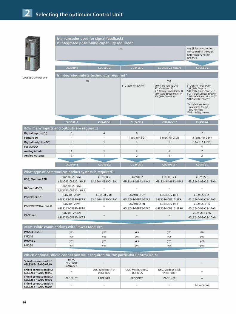
CU250S-2 Control Unit
Is an encoder used for signal feedback? Is integrated positioning capability required?
no yes (EPos positioning functionality through Extended Function license)
CU230P-2 CU240B-2 CU240E-2 CU240E-2 Failsafe CU250S-2
Is integrated safety technology required?no yes
STO (Safe Torque Off) STO (Safe Torque Off) SS1 (Safe Stop 1) SLS (Safely Limited Speed) SSM (Safe Speed Monitor) SDI (Safe Direction)
STO (Safe Torque Off) SS1 (Safe Stop 1) SBC (Safe Brake Control)1) SLS (Safely Limited Speed)2) SSM (Safe Speed Monitor)2) SDI (Safe Direction)2) 1) A Safe Brake Relay
is required for the SBC function
2) With Safety license
CU230P-2 CU240B-2 CU240E-2 CU240E-2 F CU250S-2
How many inputs and outputs are required?Digital inputs (DI) 6 4 6 6 11Failsafe DI – – 1 (opt. for 2 DI) 3 (opt. for 2 DI) 3 (opt. for 2 DI)Digital outputs (DO) 3 1 3 3 3 (opt. 1 F-DO)Fast DI/DO – – – – 4Analog inputs 4 1 2 2 2Analog outputs 2 1 2 2 2
CU230P-2 CU240B-2 CU240E-2 CU240E-2 F CU250S-2
What type of communication/bus system is required?
USS, Modbus RTUCU230P-2 HVAC CU240B-2 CU240E-2 CU240E-2 F CU250S-2
6SL3243-0BB30-1HA3 6SL3244-0BB00-1BA1 6SL3244-0BB12-1BA1 6SL3244-0BB13-1BA1 6SL3246-0BA22-1BA0
BACnet MS/TPCU230P-2 HVAC
– – – –6SL3243-0BB30-1HA3
PROFIBUS DPCU230P-2 DP CU240B-2 DP CU240E-2 DP CU240E-2 DP-F CU250S-2 DP
6SL3243-0BB30-1PA3 6SL3244-0BB00-1PA1 6SL3244-0BB12-1PA1 6SL3244-0BB13-1PA1 6SL3246-0BA22-1PA0
PROFINET/EtherNet IPCU230P-2 PN
–CU240E-2 PN CU240E-2 PN-F CU250S-2 PN
6SL3243-0BB30-1FA0 6SL3244-0BB12-1FA0 6SL3244-0BB13-1FA0 6SL3246-0BA22-1FA0
CANopenCU230P-2 CAN
– – –CU250S-2 CAN
6SL3243-0BB30-1CA3 6SL3246-0BA22-1CA0
Permissible combinations with Power ModulesPM230 (IP20) yes yes yes yes noPM240 yes yes yes yes yesPM240-2 yes yes yes yes yesPM250 yes yes yes yes yes
Which optional shield connection kit is required for the particular Control Unit?Shield connection kit 1 6SL3264-1EA00-0FA0
HVAC PROFIBUS CANopen
– – – –
Shield connection kit 2 6SL3264-1EA00-0HA0 – USS, Modbus RTU,
PROFIBUSUSS, Modbus RTU,
PROFIBUSUSS, Modbus RTU,
PROFIBUS –
Shield connection kit 3 6SL3264-1EA00-0HB0 PROFINET PROFINET PROFINET PROFINET –
Shield connection kit 4 6SL3264-1EA00-0LA0 – – – – All versions
Selecting the optimum Control Unit2
17
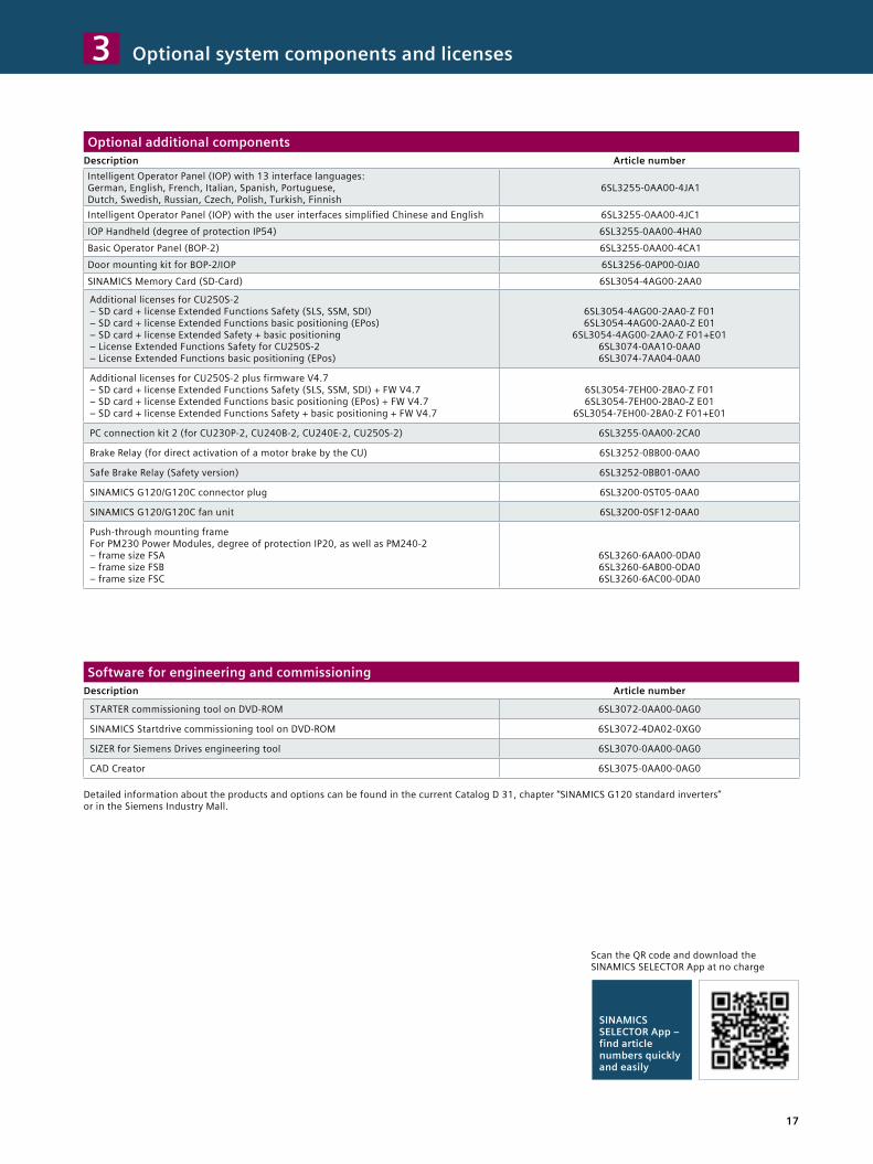
Optional additional componentsDescription Article numberIntelligent Operator Panel (IOP) with 13 interface languages: German, English, French, Italian, Spanish, Portuguese, Dutch, Swedish, Russian, Czech, Polish, Turkish, Finnish
6SL3255-0AA00-4JA1
Intelligent Operator Panel (IOP) with the user interfaces simplified Chinese and English 6SL3255-0AA00-4JC1IOP Handheld (degree of protection IP54) 6SL3255-0AA00-4HA0Basic Operator Panel (BOP-2) 6SL3255-0AA00-4CA1Door mounting kit for BOP-2/IOP 6SL3256-0AP00-0JA0SINAMICS Memory Card (SD-Card) 6SL3054-4AG00-2AA0
Additional licenses for CU250S-2 – SD card + license Extended Functions Safety (SLS, SSM, SDI) – SD card + license Extended Functions basic positioning (EPos) – SD card + license Extended Safety + basic positioning – License Extended Functions Safety for CU250S-2 – License Extended Functions basic positioning (EPos)
6SL3054-4AG00-2AA0-Z F01 6SL3054-4AG00-2AA0-Z E01
6SL3054-4AG00-2AA0-Z F01+E01 6SL3074-0AA10-0AA0 6SL3074-7AA04-0AA0
Additional licenses for CU250S-2 plus firmware V4.7 – SD card + license Extended Functions Safety (SLS, SSM, SDI) + FW V4.7 – SD card + license Extended Functions basic positioning (EPos) + FW V4.7 – SD card + license Extended Functions Safety + basic positioning + FW V4.7
6SL3054-7EH00-2BA0-Z F01 6SL3054-7EH00-2BA0-Z E01
6SL3054-7EH00-2BA0-Z F01+E01
PC connection kit 2 (for CU230P-2, CU240B-2, CU240E-2, CU250S-2) 6SL3255-0AA00-2CA0
Brake Relay (for direct activation of a motor brake by the CU) 6SL3252-0BB00-0AA0
Safe Brake Relay (Safety version) 6SL3252-0BB01-0AA0
SINAMICS G120/G120C connector plug 6SL3200-0ST05-0AA0
SINAMICS G120/G120C fan unit 6SL3200-0SF12-0AA0
Push-through mounting frame For PM230 Power Modules, degree of protection IP20, as well as PM240-2 – frame size FSA – frame size FSB – frame size FSC
6SL3260-6AA00-0DA0 6SL3260-6AB00-0DA0 6SL3260-6AC00-0DA0
Software for engineering and commissioningDescription Article number
STARTER commissioning tool on DVD-ROM 6SL3072-0AA00-0AG0
SINAMICS Startdrive commissioning tool on DVD-ROM 6SL3072-4DA02-0XG0
SIZER for Siemens Drives engineering tool 6SL3070-0AA00-0AG0
CAD Creator 6SL3075-0AA00-0AG0
Detailed information about the products and options can be found in the current Catalog D 31, chapter “SINAMICS G120 standard inverters” or in the Siemens Industry Mall.
Optional system components and licenses
Scan the QR code and download the SINAMICS SELECTOR App at no charge
SINAMICS SELECTOR App – find article numbers quickly and easily
3
18
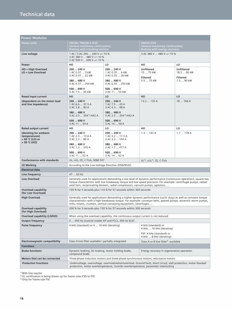
Power ModulesPower units PM240 / PM240-2 IP20
General machinery construction; Braking with a braking resistor
PM250 IP20 General machinery construction; Braking with energy recovery
Line voltage 1 AC / 3 AC 200 ... 240 V +/–10 % 3 AC 380 V … 480 V +/–10 % 3 AC 500 V … 690 V +/–10 %
3 AC 380 V … 480 V +/–10 %
Power HO LO HO LO
HO = High Overload LO = Low Overload
200 … 240 V1 AC 0.37 ... 3 kW 3 AC 0.37 ... 22 kW
380 … 480 V3 AC 0.37 … 200 kW
500 … 690 V3 AC 7.5 … 45 kW
200 … 240 V1 AC 0.55 ... 4 kW 3 AC 0.55 ... 30 kW
380 … 480 V3 AC 0.55 … 250 kW
500 … 690 V3 AC 11 … 55 kW
Unfiltered15 ... 75 kW
Filtered5.5 ... 75 kW
Unfiltered18.5 ... 90 kW
Filtered7.5 ... 90 kW
Rated input current HO LO HO LO
(dependent on the motor load and line impedance)
200 … 240 V1 AC 6.6 ... 37.5 A 3 AC 3.8 ... 83 A
380 … 480 V3 AC 2.0 ... 3541) / 442 A
500 … 690 V3 AC 11 ... 54 A
200 … 240 V1 AC 7.5 ... 43 A 3 AC 4.3 ... 98 A
380 … 480 V3 AC 2.3 ... 3541) / 442 A
500 … 690 V3 AC 14 ... 59 A
13.2 … 135 A 18 ... 166 A
Rated output current HO LO HO LO
(derating for ambient temperatures) > 40 °C (LO) or > 50 °C (HO)
200 … 240 V1 AC 2.3 ... 13.6 A 3 AC 2.3 … 80 A
380 … 480 V3 AC 1.3 … 370 A
500 … 690 V3 AC 11 … 52 A
200 … 240 V1 AC 3.2 ... 17.5 A 3 AC 3.2 … 104 A
380 … 480 V3 AC 1.7 … 477 A
500 … 690 V3 AC 14 … 62 A
1.3 ... 145 A 1.7 ... 178 A
Conformance with standards UL, cUL, CE, C-Tick, SEMI F47 UL2), cUL2), CE, C-Tick
CE Marking According to the Low-Voltage Directive 2006/95/EC
Electrical data
Line frequency 47 ... 63 Hz
Low Overload Generally used for applications demanding a low level of dynamic performance (continuous operation), square-law torque characteristic with low breakaway torque and low speed precision. For example: centrifugal pumps, radial/axial fans, reciprocating blowers, radial compressors, vacuum pumps, agitators, …
Overload capability (for Low Overload)
150 % for 3 seconds plus 110 % for 57 seconds within 300 seconds
High Overload Generally used for applications demanding a higher dynamic performance (cyclic duty) as well as constant torque characteristics with a high breakaway torque. For example: conveyor belts, geared pumps, excentric worm pumps, mills, mixers, crushers, vertical conveying equipment, centrifuges, …
Overload capability (for High Overload)
200 % for 3 seconds plus 150 % for 57 seconds within 300 seconds
Overload capability (LO/HO) When using the overload capability, the continuous output current is not reduced
Output frequency 0 ... 550 Hz (control modes V/f and FCC), 200 Hz SLVC
Pulse frequency 4 kHz (standard) or 4 ... 16 kHz (derating) 4 kHz (standard) or 4 kHz ... 16 kHz (derating)
FSF: 4 kHz (standard) or 4 kHz ... 8 kHz (derating)
Electromagnetic compatibility Class A line filter available / partially integrated Class A or B line filter3) available
Functions
Brake functions Dynamic braking, DC braking, motor holding brake, compound brake
Energy recovery in regenerative operation
Motors that can be connected Three-phase induction motors and three-phase synchronous motors, reluctance motors
Protection functions Undervoltage, overvoltage, overmodulation/overload. Ground fault, short circuit, stall protection, motor blocked protection, motor overtemperature, inverter overtemperature, parameter interlocking
1) With line reactor2) UL certification is being drawn up for frame sizes FSD to FSF3) Only for frame size FSC
Technical data
19
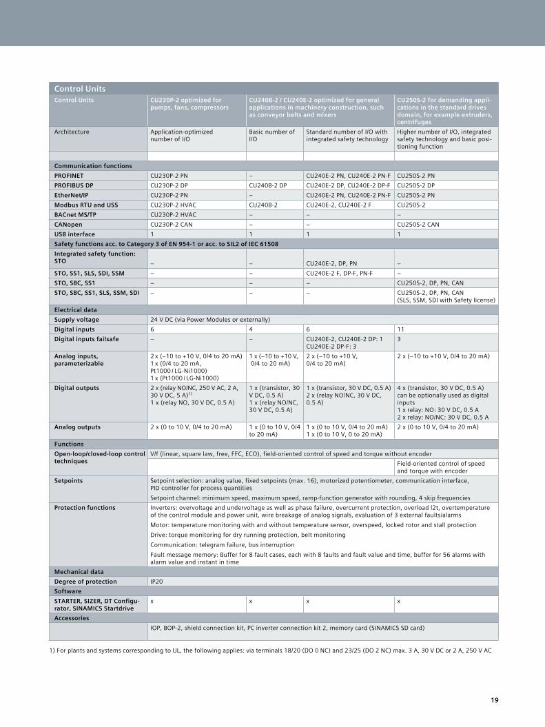
Control UnitsControl Units CU230P-2 optimized for
pumps, fans, compressorsCU240B-2 / CU240E-2 optimized for general applications in machinery construction, such as conveyor belts and mixers
CU250S-2 for demanding appli-cations in the standard drives domain, for example extruders, centrifuges
Architecture Application-optimized number of I/O
Basic number of I/O
Standard number of I/O with integrated safety technology
Higher number of I/O, integrated safety technology and basic posi-tioning function
Communication functionsPROFINET CU230P-2 PN – CU240E-2 PN, CU240E-2 PN-F CU250S-2 PNPROFIBUS DP CU230P-2 DP CU240B-2 DP CU240E-2 DP, CU240E-2 DP-F CU250S-2 DPEtherNet/IP CU230P-2 PN – CU240E-2 PN, CU240E-2 PN-F CU250S-2 PNModbus RTU and USS CU230P-2 HVAC CU240B-2 CU240E-2, CU240E-2 F CU250S-2BACnet MS/TP CU230P-2 HVAC – – –CANopen CU230P-2 CAN – – CU250S-2 CANUSB interface 1 1 1 1Safety functions acc. to Category 3 of EN 954-1 or acc. to SIL2 of IEC 61508Integrated safety function:STO – – CU240E-2, DP, PN –STO, SS1, SLS, SDI, SSM – – CU240E-2 F, DP-F, PN-F –STO, SBC, SS1 – – – CU250S-2, DP, PN, CANSTO, SBC, SS1, SLS, SSM, SDI – – – CU250S-2, DP, PN, CAN
(SLS, SSM, SDI with Safety license)Electrical dataSupply voltage 24 V DC (via Power Modules or externally)Digital inputs 6 4 6 11Digital inputs failsafe – – CU240E-2, CU240E-2 DP: 1
CU240E-2 DP-F: 33
Analog inputs, parameterizable
2 x (–10 to +10 V, 0/4 to 20 mA) 1 x (0/4 to 20 mA, Pt1000 / LG-Ni1000) 1 x (Pt1000 / LG-Ni1000)
1 x (–10 to +10 V, 0/4 to 20 mA)
2 x (–10 to +10 V, 0/4 to 20 mA)
2 x (–10 to +10 V, 0/4 to 20 mA)
Digital outputs 2 x (relay NO/NC, 250 V AC, 2 A, 30 V DC, 5 A)1) 1 x (relay NO, 30 V DC, 0.5 A)
1 x (transistor, 30 V DC, 0.5 A)1 x (relay NO/NC, 30 V DC, 0.5 A)
1 x (transistor, 30 V DC, 0.5 A)2 x (relay NO/NC, 30 V DC, 0.5 A)
4 x (transistor, 30 V DC, 0.5 A) can be optionally used as digital inputs1 x relay: NO: 30 V DC, 0.5 A 2 x relay: NO/NC: 30 V DC, 0.5 A
Analog outputs 2 x (0 to 10 V, 0/4 to 20 mA) 1 x (0 to 10 V, 0/4 to 20 mA)
1 x (0 to 10 V, 0/4 to 20 mA) 1 x (0 to 10 V, 0 to 20 mA)
2 x (0 to 10 V, 0/4 to 20 mA)
FunctionsOpen-loop/closed-loop control techniques
V/f (linear, square law, free, FFC, ECO), field-oriented control of speed and torque without encoderField-oriented control of speed and torque with encoder
Setpoints Setpoint selection: analog value, fixed setpoints (max. 16), motorized potentiometer, communication interface, PID controller for process quantitiesSetpoint channel: minimum speed, maximum speed, ramp-function generator with rounding, 4 skip frequencies
Protection functions Inverters: overvoltage and undervoltage as well as phase failure, overcurrent protection, overload l2t, overtemperature of the control module and power unit, wire breakage of analog signals, evaluation of 3 external faults/alarmsMotor: temperature monitoring with and without temperature sensor, overspeed, locked rotor and stall protectionDrive: torque monitoring for dry running protection, belt monitoringCommunication: telegram failure, bus interruptionFault message memory: Buffer for 8 fault cases, each with 8 faults and fault value and time, buffer for 56 alarms with alarm value and instant in time
Mechanical dataDegree of protection IP20SoftwareSTARTER, SIZER, DT Configu-rator, SINAMICS Startdrive
x x x x
AccessoriesIOP, BOP-2, shield connection kit, PC inverter connection kit 2, memory card (SINAMICS SD card)
1) For plants and systems corresponding to UL, the following applies: via terminals 18/20 (DO 0 NC) and 23/25 (DO 2 NC) max. 3 A, 30 V DC or 2 A, 250 V AC
Technical data

Find out more:
siemens.com/ids
Subject to change without prior notice Article No. E80001-A400-P210-V3-7600 Dispo 21500 WÜ/66762 V6.MKSINA.WES WS 04155.0 Printed in Germany © Siemens AG 2015
The information provided in this brochure contains merely general descriptions or characteristics of performance which in case of actual use do not always apply as described or which may change as a result of further development of the products. An obligation to provide the respective character-istics shall only exist if expressly agreed in the terms of contract.. All product designations may be trademarks or product names of Siemens AG or supplier com-panies whose use by third parties for their own purposes could violate the rights of the owners.
Follow us on: twitter.com/siemensindustry youtube.com/siemens
Experience how Integrated Drive Systems can boost the competitiveness of production plants and entire companies in every sector.
The advantages of Integrated Drive Systems at a glance
Siemens AG Digital Factory P.O. Box 31 80 91050 Erlangen GERMANY