Embed Size (px)
Citation preview
1
SIMPLE SHEAR AND BENDER ELEMENT TESTING OF GEOFOAM
S. Sivathayalan1 , D. Negussey2 , and Y. P. Vaid3
ABSTRACT
The engineering properties of geofoam (expanded polystyrene, EPS) were investigated, and the
results of a series of simple shear and bender element tests on geofoam are presented. The
measured simple shear response was compared to the response of geofoam under compression
loading reported in the literature. The shear modulus and its variation with strain level were
assessed using specimens subjected to a vertical stress of 28 kPa. Such studies provide means of
assessing the response of geofoam under seismic loading. Modulus reduction curves for
geofoam at different densities are similar, even though the actual shear modulus increases with
density and is loading rate dependent. Initial results of a complementary study to assess the
elastic modulus at low strain levels using bender element tests are also presented.
KEY WORDS
Bender elements, compression, density, EPS, geofoam, modulus, simple shear, p-wave, velocity
1 Department of Civil and Environmental Engineering, Carleton University, Ottawa, ON, Canada
2 Geofoam Research Center, Syracuse University, Syracuse. NY, USA
3 Dept of Civil and Environmental Engineering, University of British Columbia, Vancouver, B.C., Canada
2
INTRODUCTION
Low density expanded polystyrene (EPS) material has been used in geotechnical engineering
applications for several years. This synthetic material, commonly termed geofoam, is primarily
used as a low weight soil replacement refill in order to decrease the overburden pressure and thus
to limit settlements, and for insulation purposes. The density of geofoam can be varied based on
the production process, and those that have a density of about 20 ~ 30 kg/m3 are commonly used
in geotechnical engineering applications. To date investigations of geofoam behaviour have
mainly focused on monotonic compression loading, interface strength and creep response for
design under steady load conditions. The use of geofoam is becoming increasingly common.
Further understanding of the mechanical behaviour of geofoam and its interaction performance is
useful for design. Under field loading conditions geofoam fills may be subjected to seismic and
other periodic loads. Fundamental studies are required to understand and model the response
under such loading. This paper presents the initial results of a study performed to assess the
deformation characteristics of geofoam under controlled conditions in the laboratory.
MECHANICAL BEHAVIOUR OF GEOFOAM
An understanding of the mechanical behaviour of geofoam is essential for proper design in
geotechnical applications. Even though geofoams have been in use for about 30 years, studies of
its mechanical behaviour under diverse loading conditions have so far been limited. Earlier
interest was on the compressive strength of geofoam (Sorlie et al., 1979, van Dorp, 1988,
Eriksson and Trank, 1991, Duskov, 1997, Negussey, 1997, BASF, 1998, and Elragi 2000),
generally based on testing small samples at relatively faster loading rates. Negussey and
Jahanandish (1993) studied the one dimensional compression behaviour of geofoam in contrast
with the consolidation characteristics of soils. These studies indicate the behaviour of geofoam
under compressive stresses is density, stress level, and loading rate dependent, and the stress -
strain response may be approximated as elastic at low strain levels. Creep deformation in small
samples was found to be relatively small up to stresses of about 30 to 40 percent of the

3
compressive strength at strain levels of 5 to 10 percent. This background has been the basis for
most current methods of design.
In the field, geofoam can be subjected to compressive as well as shear loads. An understanding
of the behaviour under shear loading is important in the context of seismic loading. The first
step in assessing seismic response is to comprehend the nature of shear stress-strain behaviour,
factors influencing shear modulus, and the degradation of modulus with strain level. The shear
modulus of soils depends on density among other factors, and extensive data is available in the
literature covering modulus degradation with strain level for several soil types. While there is
some published information covering repeated loading and creep effects (Hillman, 1996),
investigations that address dynamic geotechnical behavior of geofoam are severely limited.
EQUIPMENT & TEST PROCEDURE
The stress stain behaviour of geofoam was assessed under simple shear loading conditions
using an NGI type simple shear device. The loading pedestals in the device were modified to
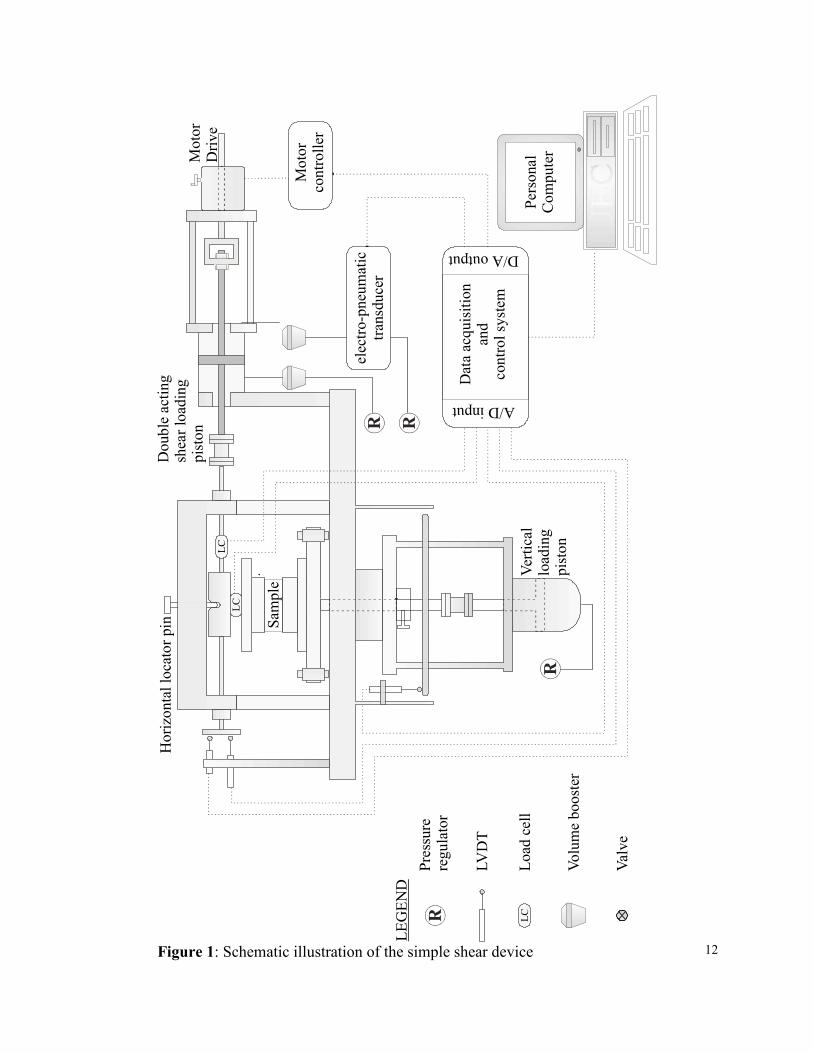
properly accommodate the geofoam specimen. Figure 1 shows a schematic diagram of the simple
shear apparatus used. A single acting air piston applies the vertical load to the sample. The
horizontal shear stress can be applied either by the double acting pneumatic piston for stress
controlled, or by the variable speed motor drive for strain controlled loading. The loading
mechanism permits switching to displacement controlled from stress controlled loading during a
test. Normal and shear loads were measured by the vertical and horizontal load cells. Vertical
deformation was monitored by a displacement transducer, and shear distortion was measured by
horizontally positioned displacement transducers (LVDT). Two LVDTs were used in the
horizontal direction in order to increase the available displacement range and yet have high
measurement resolution at low strain levels.
Cyclic loading was applied by changing the pressure in one of the two chambers of the double
acting piston using an electro-pneumatic transducer. The electro pneumatic transducer was

4
controlled by a computer. An air volume booster was connected to the chambers of the double
acting piston in order to maintain constant amplitude of cyclic shear load as large deformations
occurred. The high resolution, high-speed data acquisition system enabled consistent
determination of stresses and strains. The normal and shear stresses have a measurement
resolution of about 0.3 kPa, and the vertical strain has a resolution of about 0.01%. The
resolution of the shear strain evaluation was about 0.01% for shear strains up to about 10%, and
0.05% for shear strains in excess of 10%. The electro-pneumatic transducer has a resolution of
about 0.3 kPa. This simple shear device has been used extensively to characterize the constant
volume behaviour of sands. Further details of the equipment can be found in Vaid and
Sivathayalan (1996).
One of the major challenges faced during the early stages of the test program was to ensure that
the shear load was properly transmitted to the specimen at the pedestal-specimen interface
(without slippage). When testing soils, shear stresses are transmitted by using approximately
1mm high ribs or pins in the pedestals. Such a setup was not suitable for testing geofoam, and an
alternative way to glue the geofoam to the pedestal was devised. Different adhesives were
evaluated and fast-curing epoxy was found to be the most suitable.
Tests were performed on geofoam samples of average 20 and 30 kg/m 3 densities. Cylindrical
geofoam specimens of 70 mm diameter and about 20 mm high were glued to the top and bottom
pedestals. A vertical stress of about 5 kPa was applied just after set-up, and sufficient time was
allowed for the epoxy to cure and form a strong bond. Subsequently, a vertical stress of 28 kPa
(to simulate a pavement dead load) was applied, and the vertical compression of the geofoam
was monitored during the loading. The prescribed horizontal stress cycles were applied under
this essentially constant vertical stress level. Both stress and strain controlled loading were used
to apply the horizontal shear stresses.
The elastic modulus of geofoam was determined from “bender element” test results. A bender
element is a special piezoceramic transducer capable of converting electrical pulses into
mechanical vibration and vice-versa. They are being increasingly used in geotechnical

5
engineering to measure the elastic properties of soils since Dyvik and Madshus (1985)
demonstrated excellent agreement in shear modulus determined using resonant column and
bender element tests. Strains generated by bender elements in testing of soils are in the range of
10-3 to 10-5 % (Brignoli et al. 1996). Therefore this test may be suitable to evaluate the elastic
properties of geofoam. Details of the use of bender elements in soil dynamics is given by Gohl
and Finn (1991).
The top and bottom pedestals of a conventional triaxial cell were modified to include bender
elements. A vibrating bender element transmitter (approximately 12 mm x 10 mm in size) was
placed at the bottom pedestal and the receiving element at the top pedestal as schematically
illustrated in Figure 2. Cylindrical geofoam specimens of 20 kg/m3 density 60 mm diameter and
about 120 mm height were tested under a seating load of about 5 kPa. The bender elements were
placed parallel to the base of the cell to generate compression waves during excitation. The time
required for the elastic waves to travel from the bottom to the top of the geofoam specimen was
measured using an oscilloscope that traces the voltage - time histories of the transmitted and
received signals. A function generator capable of applying various waveforms over a range of
frequencies was used to excite the transmitting element. The response of the received element
was the strongest for frequencies ranging from about 400 to 1500 Hz for sinusoidal pulses at
maximum amplitude of ±10 V. The time of travel was taken as the time difference between the
peaks in the transmitted and the received signals.
TEST RESULTS
AXIAL COMPRESSION OF GEOFOAM
The axial compressibility of the geofoam was measured by using the simple shear device. No
adhesives were used when testing axial compressibility since the loading was only axial and the
specimen was confined between the end platens. A vertical stress of up to 100 kPa was applied
in increments over a period of 12 hours and the vertical deformation was monitored. This is
6
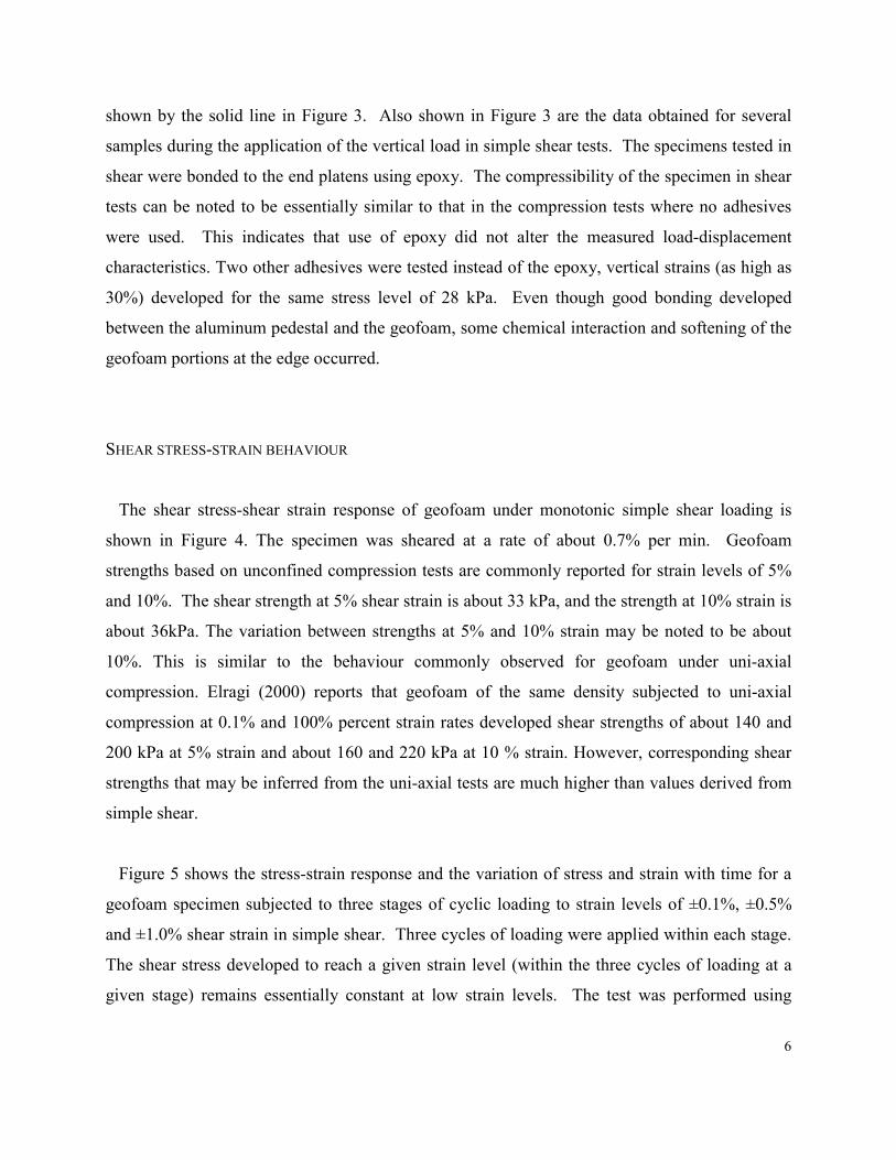
shown by the solid line in Figure 3. Also shown in Figure 3 are the data obtained for several
samples during the application of the vertical load in simple shear tests. The specimens tested in
shear were bonded to the end platens using epoxy. The compressibility of the specimen in shear
tests can be noted to be essentially similar to that in the compression tests where no adhesives
were used. This indicates that use of epoxy did not alter the measured load-displacement
characteristics. Two other adhesives were tested instead of the epoxy, vertical strains (as high as
30%) developed for the same stress level of 28 kPa. Even though good bonding developed
between the aluminum pedestal and the geofoam, some chemical interaction and softening of the
geofoam portions at the edge occurred.
SHEAR STRESS-STRAIN BEHAVIOUR
The shear stress-shear strain response of geofoam under monotonic simple shear loading is
shown in Figure 4. The specimen was sheared at a rate of about 0.7% per min. Geofoam
strengths based on unconfined compression tests are commonly reported for strain levels of 5%
and 10%. The shear strength at 5% shear strain is about 33 kPa, and the strength at 10% strain is
about 36kPa. The variation between strengths at 5% and 10% strain may be noted to be about
10%. This is similar to the behaviour commonly observed for geofoam under uni-axial
compression. Elragi (2000) reports that geofoam of the same density subjected to uni-axial
compression at 0.1% and 100% percent strain rates developed shear strengths of about 140 and
200 kPa at 5% strain and about 160 and 220 kPa at 10 % strain. However, corresponding shear
strengths that may be inferred from the uni-axial tests are much higher than values derived from
simple shear.
Figure 5 shows the stress-strain response and the variation of stress and strain with time for a
geofoam specimen subjected to three stages of cyclic loading to strain levels of ±0.1%, ±0.5%
and ±1.0% shear strain in simple shear. Three cycles of loading were applied within each stage.
The shear stress developed to reach a given strain level (within the three cycles of loading at a
given stage) remains essentially constant at low strain levels. The test was performed using

7
displacement controlled loading, and the system compliance (mostly from the gear slack) was the
cause of the spikes and flat peaks in both the strain and stress traces. However, no such
compliance problems developed, when the load-controlled mechanism was used to apply the
cyclic stresses as shown in Figure 6. Again, three stages of loading, but this time with ten cycles
per stage, at shear stress levels of ±5, ±10 and ±15 kPa, were applied. One stress cycle was
applied per minute, and this resulted in variable strain-loading rate. The loading rate during the
first stage corresponded to about 0.8% shear strain per min, and the third about 2.5 % per min.
The strains developed within each stage may be noted to be essentially constant. The secant
shear modulus under a cyclic stress level of ±10 kPa remains at an essentially constant value of
about 2.2 MPa. A constant shear modulus within a stage of loading indicates that the applied
cyclic loading does not cause degradation in the modulus at the stress level. However, when
larger amplitudes of cyclic shear stresses were applied, as illustrated in figure 7, the specimen
exhibited some softening within a “stage” due to cyclic loading. The initial secant shear
modulus under the cyclic stress level of ±50 kPa was about 1.3 MPa, but decreased to about 1
MPa during the next 10 loading cycles at the same stress level.
Figure 8 shows the variation of shear modulus in simple shear with strain level. The initial
shear moduli determined under simple shear loading are about 1.7 and 2.3 MPa for geofoam of
20 and 30 kg/m3, respectively, when tested under a constant strain loading rate of about 0.7 %
per min. A significant degradation in shear modulus may be noted at initial low strain levels.
The modulus is higher for denser geofoam, but the rate of modulus reduction appears essentially
independent of the density. Dependence of Young’s modulus on density and size of geofoam has
been established from uni-axial compression tests (Elragi et al, 2000). Modulus degradation with
strain has been well established in soils, and the characteristics of the modulus degradation curve
in geofoam appear to be similar to that of soils. The modulus variation in a stress controlled
cyclic test performed at a rate of one stress cycle per minute is also shown in the figure. The
strain rate in this test varied during the test, and is identified at each data point in the graph. The
rate of modulus reduction is smaller in this case because the increasing loading rate at higher
strains compensates for the modulus degradation with increasing strain. The influence of loading
rate on the behaviour of geofoam has been recognized in previous studies based on compression
8
tests (Elragi 2000). Shear modulus values determined by testing small samples are significantly
lower than can be inferred from Young’s modulus values derived from compression tests on
large samples.
The maximum shear modulus Gmax and Young’s modulus Emax at very low strains represent
upper bound values for these critical parameters but are difficult to obtain from shear or
compression tests that rely on direct measurement of deformations. Bender element testing
provides a convenient means for evaluating the elastic properties of geofoam by using
established relationships between wave velocities and elastic modulus. Shear modulus can be
calculated using the shear wave (s-wave) velocity, and Young’s modulus can be calculated using
the compression wave (p-wave) velocity. Generating s-waves require insertion of elements into
the geofoam specimen while maintaining tight contact. The elastic wave velocities in this study
were only p-waves. S-wave velocity measurements will be covered subsequently.
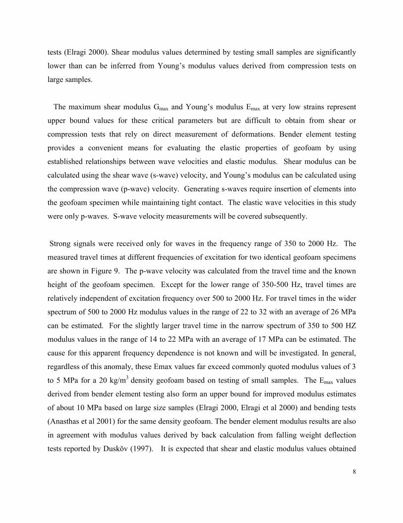
Strong signals were received only for waves in the frequency range of 350 to 2000 Hz. The
measured travel times at different frequencies of excitation for two identical geofoam specimens
are shown in Figure 9. The p-wave velocity was calculated from the travel time and the known
height of the geofoam specimen. Except for the lower range of 350-500 Hz, travel times are
relatively independent of excitation frequency over 500 to 2000 Hz. For travel times in the wider
spectrum of 500 to 2000 Hz modulus values in the range of 22 to 32 with an average of 26 MPa
can be estimated. For the slightly larger travel time in the narrow spectrum of 350 to 500 HZ
modulus values in the range of 14 to 22 MPa with an average of 17 MPa can be estimated. The
cause for this apparent frequency dependence is not known and will be investigated. In general,
regardless of this anomaly, these Emax values far exceed commonly quoted modulus values of 3
to 5 MPa for a 20 kg/m3 density geofoam based on testing of small samples. The Emax values
derived from bender element testing also form an upper bound for improved modulus estimates
of about 10 MPa based on large size samples (Elragi 2000, Elragi et al 2000) and bending tests
(Anasthas et al 2001) for the same density geofoam. The bender element modulus results are also
in agreement with modulus values derived by back calculation from falling weight deflection
tests reported by Duskŏv (1997). It is expected that shear and elastic modulus values obtained

9
using bender elements will yield alternative means of evaluating Poisson’s ratio for geofoam.
Brocanelli and Rinaldi (1998) have recommended a technique to measure material damping in
addition to modulus using bender elements in soils. Extending their frequency domain approach
in testing geofoam may provide useful data at low strains. Further comprehensive studies are
needed to fully explore the material behaviour at these low strain levels.
SUMMARY
The initial results of an experimental study of the shear behaviour of geofoam are presented.
The objective of the test program was to understand the behaviour of geofoam under dynamic
loading conditions using controlled laboratory tests. The response of geofoam to shear depends
on the loading rate and the density of geofoam and is weaker in strength than for compression
loading. The shear modulus in cyclic loading is not influenced by the stress history at low stress
levels. However, repeated cyclic loadings under larger shear stress induce softening. The shear
modulus of geofoam increases with density and reduces with strain level. The rate of modulus
reduction with strain does not appear to be influenced by the density of geofoam. These
characteristics of modulus degradation in geofoam are similar to that of soils. Attempts to
characterize the response using bender elements is at an early stage, and measured compression
wave velocities indicate that Emax for 20 kg/m3 density geofoam is in the order of 20 MPa.
Further studies will include detailed characterization of the stress-strain behaviour, and shear
wave velocity measurements.
ACKNOWLEDGEMENTS
The research was carried out at the University of British Columbia geotechnical laboratory.
The technical assistance of Harald Schrempp, John Wong and Scott Jackson in fabricating the
testing apparatus, instrumentation design, data acquisition and test control systems is gratefully
acknowledged. This research was partly supported by a grant from the Natural Sciences and
Engineering Council of Canada and by the support of Huntsman Corporation to the Geofoam
Research Center at Syracuse University.

10
REFERENCES
BASF Corp., 1998, “Styropor foam as a lightweight construction material for road base-
courses", Styropor Technical Information, Ludwigshafen, Germany
Brignoli, E. G. M., Gotti, M. and Stokoe, K. J., 1996, “Measurement of Shear Waves in
Laboratory Specimens by Means of Piezoelectric Transducers”, ASTM Geotechnical Testing
Journal, Vol.19, No. 4, pp. 384-397
Brocanelli, D. and Rinaldi, V., 1998, “Measurement of Low-strain Material Damping and Wave
Velocity with Bender Elements in the Frequency Domain”, Canadian Geotechnical Journal,
Vol. 35, No. 6, pp. 1032-1040
Duskov, M., 1997, “EPS as a Light Weight Sub-Base Material in Pavement Structures”, Ph.D.
Thesis, Delft University of Technology, Delft, Netherlands
Dyvik, R. and Madshus, C., 1985, “Lab Measurements of Gmax Using Bender Elements”,
Proceedings: Advances in the Art of Testing Soils Under Cyclic Conditions, Ed: Khosla, V. K.,
Detroit, MI, USA. Oct 24, pp.186 - 196
Elragi, A., 2000, “Selected Engineering Properties and Applications of EPS Geofoam”, Ph.D.
Thesis, State University of New York, Syracuse, N.Y
Elragi, A., Negussey, D., and Kyanka, G. (2000), “Sample Size Effects on the Behavior of EPS
Geofoam”, Proceedings of the Soft Ground Technology Conference, Noordwijkerhout,
Netherlands
Eriksson, L., and Trank, R., (1991) “Properties of Expanded Polystyrene, Laboratory
Experiments”, Swedish Geotechnical Institute, Linkoping, Sweden
Gohl, W. B. and Finn, W. D. L., 1991, “Use of Piezoceramic Bender Elements in Soil
Dynamics”, Proceedings: Recent Advances in Instrumentation, Data Acquisition and Testing
in Soil Dynamics, Eds: Bhatia, S. K., Blaney, G. W., ASCE Geotechnical Special Publication,
Orlando, FL, USA Oct. 21, pp.118-133
Hillman, R., “Research projects on EPS in Germany: Material Behaviour and Full Scale Model
Studies”, Proc. of the First International Symposium on EPS construction method, Tokyo,
Japan. October 29-30, pp.105-116.
Negussey, D. and Anasthas, N., 2001, “Young’s Modulus of EPS Geofoam by Simple Bending

11
Test”, EPS Geofoam 2001, 3rd International Conference on EPS Geofoam, Salt Lake City,
Utah, USA
Negussey, D., 1997, "Properties and Applications of Geofoam", Society of the Plastics Industry,
Inc., Washington, D.C.
Negussey, D. and Jahanandish, M., 1993, “A Comparison of Some Engineering Properties of
EPS to Soils”, Transportation Research Record No. 1418, Transportation Research Board,
Washington, D.C. pp. 43-50.
Sorlie, A., Dahlberg, R. G., Refsdal, G. and Rudd, O. E., 1979, “National Report: Norway”,
Proceedings: of the 16th World Road Congress, Vienna, Austria.
Van Dorp, T., 1988, “Expanded Polystyrene Foam as Light Fill and Foundation Material in
Road Structures”, presented at the International Congress on Expanded Polystyrene, May 10,
1988, Milan, Italy
12
Hor
izon
tal l
ocat
or p
in
Pers
onal
Com
pute
r
LEG
END
LCLC
Mot
orco
ntro
ller
elec
tro-p
neum
atic
tra
nsdu
cer
LVD
T
Pres
sure
regu
lato
r
Valv
e
Load
cel
lLC
Volu
me
boos
ter
Dat
a ac
quis
ition
and
cont
rol s
yste
m
A/D input
D/A output
Sam
ple
Verti
cal
load
ing
pist
on
Dou
ble
actin
gsh
ear l
oadi
ngpi
ston
Mot
orD
rive
Figure 1: Schematic illustration of the simple shear device

13
FunctionGenerator
Specimen
Loading cap
OscilloscopeElastic wave
σv
Figure 2: Schematic illustration of the bender element test
10 100Vertical stress (kPa)
-4.0
-3.0
-2.0
-1.0
0.0
Ver
tical
stra
in (%
)
Solid Line: Unconfined compression (This study)Dashed line: Unconfined compression (Negussey and Jehanandish 1993)Symbols: Axial compression in simple shear device
Density:Open symbols : 18 kg/m3
Closed symbols: 30 kg/m3
Figure 3: Compressibility characteristics of geofoam

14
0 2 4 6 8 10Shear strain (%)
0
10
20
30
40
Shea
r stre
ss (k
Pa)
Density, ρ = 30 kg/m3
Loading rate = 40% per hour
Vertical stress, σv = 28 kPa
Figure 4 : Shear stress - shear strain response of geofoam.

15
-1.4
-0.7
0.0
0.7
1.4Sh
ear s
train
(%
)
Density = 30 kg/m3
-12
-6
0
6
12
Shea
r stre
ss
(kPa
)
0 500 1000 1500 2000Time (sec)
-12
-6
0
6
12
Shea
r stre
ss (k
Pa)
-1.0 -0.5 0.0 0.5 1.0Shear strain (%)
Figure 5 : Stress-strain behaviour of geofoam under displacement controlled cyclic loading

16
-1.4
-0.7
0.0
0.7
1.4
Shea
r stra
in (
%)
Density = 30 kg/m3
Loading Frequency = 1 cycle/minute
-18
-12
-6
0
6
12
18
Shea
r stre
ss
(kPa
)
0 10 20 30Number of Cycles
-18
-12
-6
0
6
12
18
Shea
r stre
ss (k
Pa)
-1.0 -0.5 0.0 0.5 1.0Shear strain (%)
Vertical stress, σv = 28 kPa
Figure 6: Stress-strain behaviour of geofoam under stress controlled cyclic loading

17
0.00 0.50 1.00 1.50 2.00Shear strain (%)
0
1000
2000
3000
Shea
r Mod
ulus
(kP
a)
R = 0.7, ρ = 30 kg/m3
R = 0.7, ρ = 20 kg/m3
Strain rate, R(% per minute)
Constant
Variable
Density, ρ = 30 kg/m3
R =
0.8
R =
1.8
R =
4.3
R =
3.0
-6 -4 -2 0 2 4 6Shear strain (%)
-60
-30
0
30
60
Shea
r stre
ss (k
Pa)
Density, ρ = 30 kg/m3
Vertical stress, σv = 28 kPaLoading Frequency = 1 cycle/minute
Figure 7 : Cyclic response staged cyclic loading
Figure 8: Modulus degradation with shear strain

18
0 500 1000 1500 2000 2500Frequency (Hz)
0
40
80
120
160
200
Trav
el ti
me
(µse
c)
Density, ρ = 20 kg/m3
Test #1
Test #2
Figure 9: Variation of travel time with the frequency of the p-wave.