Embed Size (px)
Citation preview

AS/400e
Setting Up Your 5075 Expansion UnitVersion 4
SA41-5148-00
���


AS/400e
Setting Up Your 5075 Expansion UnitVersion 4
SA41-5148-00
���

NoteBefore using this information and the product it supports, be sure to read the information in “Safety and EnvironmentalNotices” on page v and “Notices” on page 31.
First Edition (May 2000)
This edition applies only to reduced instruction set computer (RISC) systems.
© Copyright International Business Machines Corporation 2000. All rights reserved.US Government Users Restricted Rights – Use, duplication or disclosure restricted by GSA ADP Schedule Contractwith IBM Corp.
Contents
Safety and Environmental Notices . . . vDanger Notices . . . . . . . . . . . . . vCaution Notices . . . . . . . . . . . . . v
Product Recycling and Disposal. . . . . . . viBattery Return Program . . . . . . . . . viEnvironmental Design . . . . . . . . . . vi
About Setting Up The 5075 ExpansionUnit (SA41–5148) . . . . . . . . . . viiWho should read this book . . . . . . . . . viiPrerequisite and related information . . . . . . viiHow to send us your comments . . . . . . . vii
Chapter 1. Preparing to set up your 5075Expansion Unit. . . . . . . . . . . . 1Hardware requirements. . . . . . . . . . . 1Planning your cable layout . . . . . . . . . 1
Identifying HSL and SPCN Cables . . . . . . 1Using a redundant link . . . . . . . . . . 2
Powering down your system unit . . . . . . . 3Installing the 7002 cable . . . . . . . . . . 3
Chapter 2. Installing your 5075 directlyto your system unit . . . . . . . . . . 7
Chapter 3. Connecting your 5075 toanother expansion unit . . . . . . . . 9Connecting your 5075 to the beginning of a loop . . 9Connecting your 5075 to the middle of a loop . . . 11Connecting your 5075 to the end of a loop . . . . 12
Chapter 4. Completing your installation 15
Chapter 5. Verifying Your NewConfiguration . . . . . . . . . . . . 17
Appendix A. Removing the covers . . . 195075 and system unit back covers . . . . . . . 195074 back cover . . . . . . . . . . . . . 195079 back cover . . . . . . . . . . . . . 20
Appendix B. Connector Locations . . . 23270 HSL connector locations . . . . . . . . . 23820 HSL connector locations . . . . . . . . . 245075 connector locations . . . . . . . . . . 245074 connector locations . . . . . . . . . . 255079 connector locations . . . . . . . . . . 26
Appendix C. System unit control panel 27
Appendix D. Cabling rules for systemswith a 503x Migration Unit . . . . . . 29
Notices . . . . . . . . . . . . . . 31Electronic Emission Notices . . . . . . . . . 32
Federal Communications Commission (FCC)Statement . . . . . . . . . . . . . . 32
Trademarks . . . . . . . . . . . . . . 33
Readers’ Comments — We’d Like toHear from You . . . . . . . . . . . 35
© Copyright IBM Corp. 2000 iii

iv Setting Up Your 5075 Expansion Unit V4R5
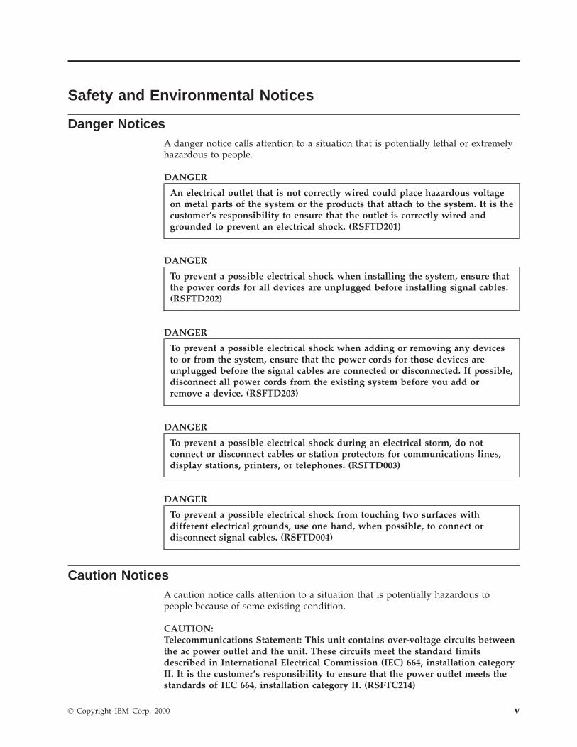
Safety and Environmental Notices
Danger NoticesA danger notice calls attention to a situation that is potentially lethal or extremelyhazardous to people.
DANGER
An electrical outlet that is not correctly wired could place hazardous voltageon metal parts of the system or the products that attach to the system. It is thecustomer’s responsibility to ensure that the outlet is correctly wired andgrounded to prevent an electrical shock. (RSFTD201)
DANGER
To prevent a possible electrical shock when installing the system, ensure thatthe power cords for all devices are unplugged before installing signal cables.(RSFTD202)
DANGER
To prevent a possible electrical shock when adding or removing any devicesto or from the system, ensure that the power cords for those devices areunplugged before the signal cables are connected or disconnected. If possible,disconnect all power cords from the existing system before you add orremove a device. (RSFTD203)
DANGER
To prevent a possible electrical shock during an electrical storm, do notconnect or disconnect cables or station protectors for communications lines,display stations, printers, or telephones. (RSFTD003)
DANGER
To prevent a possible electrical shock from touching two surfaces withdifferent electrical grounds, use one hand, when possible, to connect ordisconnect signal cables. (RSFTD004)
Caution NoticesA caution notice calls attention to a situation that is potentially hazardous topeople because of some existing condition.
CAUTION:Telecommunications Statement: This unit contains over-voltage circuits betweenthe ac power outlet and the unit. These circuits meet the standard limitsdescribed in International Electrical Commission (IEC) 664, installation categoryII. It is the customer’s responsibility to ensure that the power outlet meets thestandards of IEC 664, installation category II. (RSFTC214)
© Copyright IBM Corp. 2000 v

Product Recycling and DisposalComponents of the system, such as structural parts and circuit cards, can berecycled where recycling facilities exist. IBM does not currently collect and recycleused IBM products from customers in the United States other than those productsthat are involved in trade-in programs. Companies are available to disassemble,reutilize, recycle, or dispose of electronic products. Contact an IBM accountrepresentative for more information.
The system unit contains batteries and circuit boards with lead solder. Before youdispose of this unit, these batteries and circuit boards must be removed anddiscarded according to local regulations or recycled where facilities exist. This bookcontains specific information on each battery type where applicable.
Battery Return ProgramIn the United States, IBM has established a collection process for reuse, recycling,or proper disposal of used IBM batteries and battery packs. For information onproper disposal of the batteries in this unit, please contact IBM at 1-800-426-4333.Please have the IBM part number that is listed on the battery available when youmake your call. For information on battery disposal outside the United States,contact your local waste disposal facility.
Environmental DesignThe environmental efforts that have gone into the design of the system signifyIBM’s commitment to improve the quality of its products and processes. Some ofthese accomplishments include the elimination of the use of Class Iozone-depleting chemicals in the manufacturing process, reductions inmanufacturing wastes, and increased product energy efficiency. For moreinformation, contact an IBM account representative.
vi Setting Up Your 5075 Expansion Unit V4R5
About Setting Up The 5075 Expansion Unit (SA41–5148)
This book contains information about setting up the 5075 Expansion Unit. You caninstall your 5075 Expansion Unit yourself. It will take approximately one to threehours to install the hardware.
You can choose not to install the expansion unit yourself. You can contact IBM oran Authorized Dealer to make arrangements for them to install it for a fee.
The following list is an overview for installing the 5075 Expansion Unit:v Prepare for your 5075 Expansion Unit installation.v Power down your system unit.v Connect cables:
– Connect cables to your 5075 Expansion Unit.– Connect to your AS/400e server 270 or 820, or;– Connect cables to another expansion unit.
v Power up your 270 or 820 and your 5075 Expansion Unit.v Verify your new configuration.
Who should read this bookYou should be familiar with the AS/400 system, display, and keyboards. Youshould also know how to power down the system and perform a system initialprogram load. You should also know how to power down system peripherals suchas printers, monitors, and PCs.
Prerequisite and related informationUse the AS/400 Information Center as your starting point for looking up AS/400technical information. You can access the Information Center from the AS/400eInformation Center CD-ROM (English version: SK3T-2027) or from one of theseWeb sites:http://www.as400.ibm.com/infocenterhttp://publib.boulder.ibm.com/pubs/html/as400/infocenter.htm
The AS/400 Information Center contains advisors and important topics such as CLcommands, system application programming interfaces (APIs), logical partitioning,clustering, Java, TCP/IP, Web serving, and secured networks. It also containsInternet links to Web sites such as the AS/400 Online Library, AS/400 redbooks,and the AS/400 Technical Studio.
How to send us your commentsYour feedback is important in helping to provide the most accurate andhigh-quality information. If you have any comments about this book or any otherAS/400 documentation, fill out the readers’ comment form at the back of thisbook.v If you prefer to send comments by mail, use the readers’ comment form with the
address that is printed on the back. If you are mailing a reader’s comment form
© Copyright IBM Corp. 2000 vii
from a country other than the United States, you can give the form to the localIBM branch office or IBM representative for postage-paid mailing.
v If you prefer to send comments by FAX, use either of the following numbers:– United States and Canada: 1-800-937-3430– Other countries: 1-507-253-5192
v If you prefer to send comments electronically, use one of these e-mail addresses:– Comments on books:
[email protected], to IBMMAIL(USIB56RZ)
– Comments on the AS/400 Information Center:[email protected]
Be sure to include the following:v The name of the book.v The publication number of the book.v The page number or topic to which your comment applies.
viii Setting Up Your 5075 Expansion Unit V4R5
Chapter 1. Preparing to set up your 5075 Expansion Unit
This chapter explains what you need to do before you set up your 5075 ExpansionUnit. This includes the following tasks:1. Unpack your 5075 (refer to the instructions for unpacking that came with your
expansion unit).2. Plan layouts for your cables.3. Power down your system unit.4. Install the 7002 cable (if needed).
Before you begin the installation process, carefully plan where you will install yournew expansion unit. You should consider several factors that include size, security,and environmental factors. Before you set up your new expansion unit, refer to theAS/400 Site Preparation guide at the Technical Studio web site:
http://www.as400.ibm.com/tstudio
Hardware requirementsYou can connect your 5075 directly to your system unit if it is an AS/400e server270 or 820. If your system unit is an AS/400e server 820, you also may connectyour 5075 to another expansion unit.
If you are connecting your 5075 directly to your system unit, you need to havethese prerequisites:v An unused system power control network (SPCN) connector.v An unused high speed link (HSL) connector.
If you are connecting your 5075 to another expansion unit, your 820 can have amaximum of five expansion units in a loop.
Planning your cable layoutWhen you decide where to place your cables, do the following:v Refer to the AS/400 Site Preparation guide or web site.v Follow your site plan.v Avoid creating a safety hazard.v Avoid damaging the cable.v Avoid placing cables parallel to high-voltage lines.
Identifying HSL and SPCN CablesUse the following tables to identify your High Speed link (HSL) and System PowerControl Network cables. Your system uses HSL cables to communicate with your5075. SPCN cables are used to control power to your 5075.
Depending on your requirements, you might not have every HSL or SPCN cablelisted below.
© Copyright IBM Corp. 2000 1
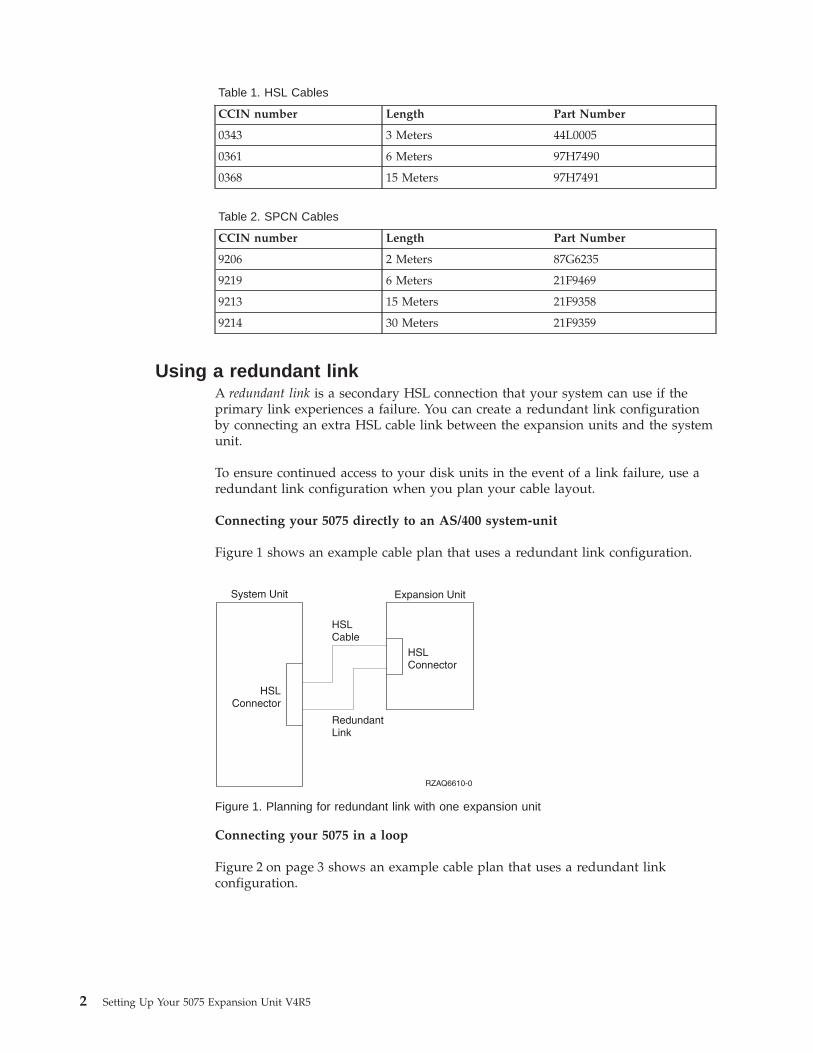
Table 1. HSL Cables
CCIN number Length Part Number
0343 3 Meters 44L0005
0361 6 Meters 97H7490
0368 15 Meters 97H7491
Table 2. SPCN Cables
CCIN number Length Part Number
9206 2 Meters 87G6235
9219 6 Meters 21F9469
9213 15 Meters 21F9358
9214 30 Meters 21F9359
Using a redundant linkA redundant link is a secondary HSL connection that your system can use if theprimary link experiences a failure. You can create a redundant link configurationby connecting an extra HSL cable link between the expansion units and the systemunit.
To ensure continued access to your disk units in the event of a link failure, use aredundant link configuration when you plan your cable layout.
Connecting your 5075 directly to an AS/400 system-unit
Figure 1 shows an example cable plan that uses a redundant link configuration.
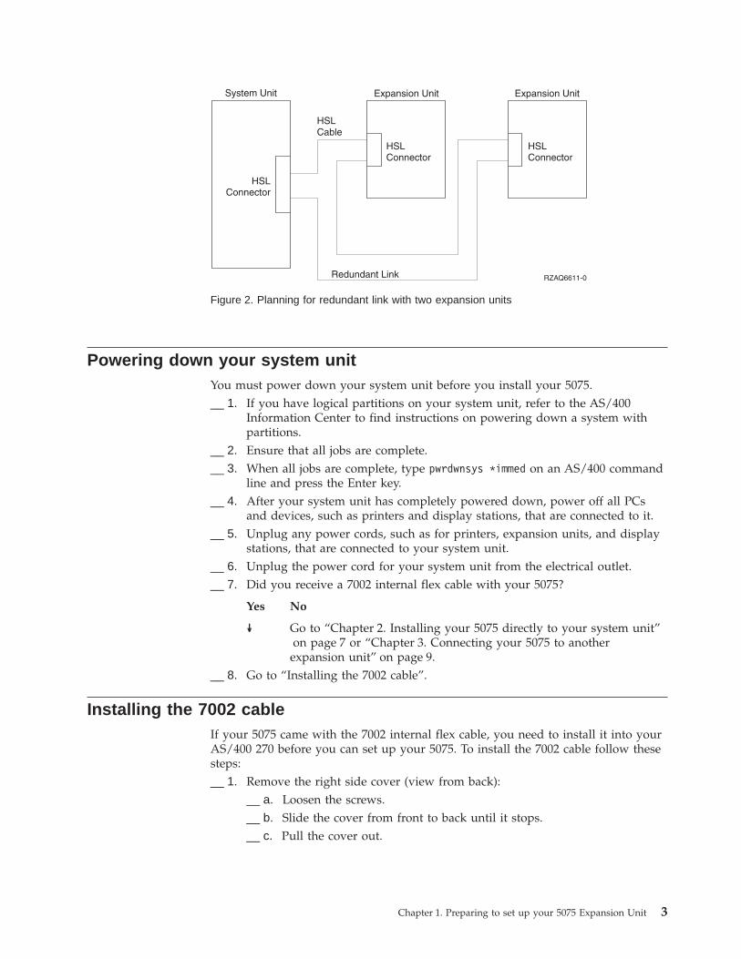
Connecting your 5075 in a loop
Figure 2 on page 3 shows an example cable plan that uses a redundant linkconfiguration.
Figure 1. Planning for redundant link with one expansion unit
2 Setting Up Your 5075 Expansion Unit V4R5
Powering down your system unitYou must power down your system unit before you install your 5075.__ 1. If you have logical partitions on your system unit, refer to the AS/400
Information Center to find instructions on powering down a system withpartitions.
__ 2. Ensure that all jobs are complete.__ 3. When all jobs are complete, type pwrdwnsys *immed on an AS/400 command
line and press the Enter key.__ 4. After your system unit has completely powered down, power off all PCs
and devices, such as printers and display stations, that are connected to it.__ 5. Unplug any power cords, such as for printers, expansion units, and display
stations, that are connected to your system unit.__ 6. Unplug the power cord for your system unit from the electrical outlet.__ 7. Did you receive a 7002 internal flex cable with your 5075?
Yes No
↓ Go to “Chapter 2. Installing your 5075 directly to your system unit”on page 7 or “Chapter 3. Connecting your 5075 to another
expansion unit” on page 9.__ 8. Go to “Installing the 7002 cable”.
Installing the 7002 cableIf your 5075 came with the 7002 internal flex cable, you need to install it into yourAS/400 270 before you can set up your 5075. To install the 7002 cable follow thesesteps:__ 1. Remove the right side cover (view from back):
__ a. Loosen the screws.__ b. Slide the cover from front to back until it stops.__ c. Pull the cover out.
Figure 2. Planning for redundant link with two expansion units
Chapter 1. Preparing to set up your 5075 Expansion Unit 3

Your system unit contains a battery that only trained personnel can replace.
CAUTION:The battery is a lithium battery. Only trained service personnel may replace thisbattery using the instructions in the Problem Analysis, Repair, and Parts servicemanual. To avoid possible explosion, do not burn or charge the battery.Exchange only with the IBM-approved part. Discard the battery as instructed bylocal regulations. (RSFTC241)
__ 2. Attach the disposable wrist strap to prevent electrostatic discharge fromdamaging a device. Figure 4 on page 5 shows an example of where to attachthe adhesive part of the foil on the wrist strap to an unpainted surface.
Figure 3. Remove system unit side cover
4 Setting Up Your 5075 Expansion Unit V4R5
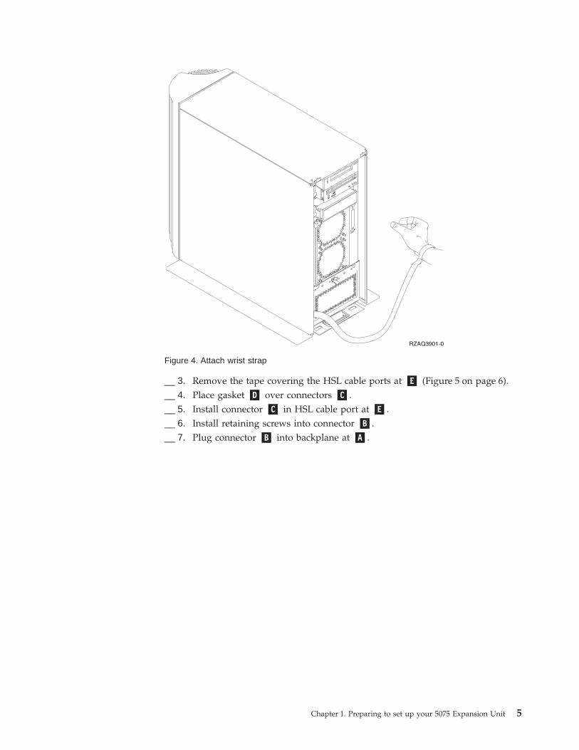
__ 3. Remove the tape covering the HSL cable ports at �E� (Figure 5 on page 6).__ 4. Place gasket �D� over connectors �C�.__ 5. Install connector �C� in HSL cable port at �E�.__ 6. Install retaining screws into connector �B�.__ 7. Plug connector �B� into backplane at �A�.
Figure 4. Attach wrist strap
Chapter 1. Preparing to set up your 5075 Expansion Unit 5
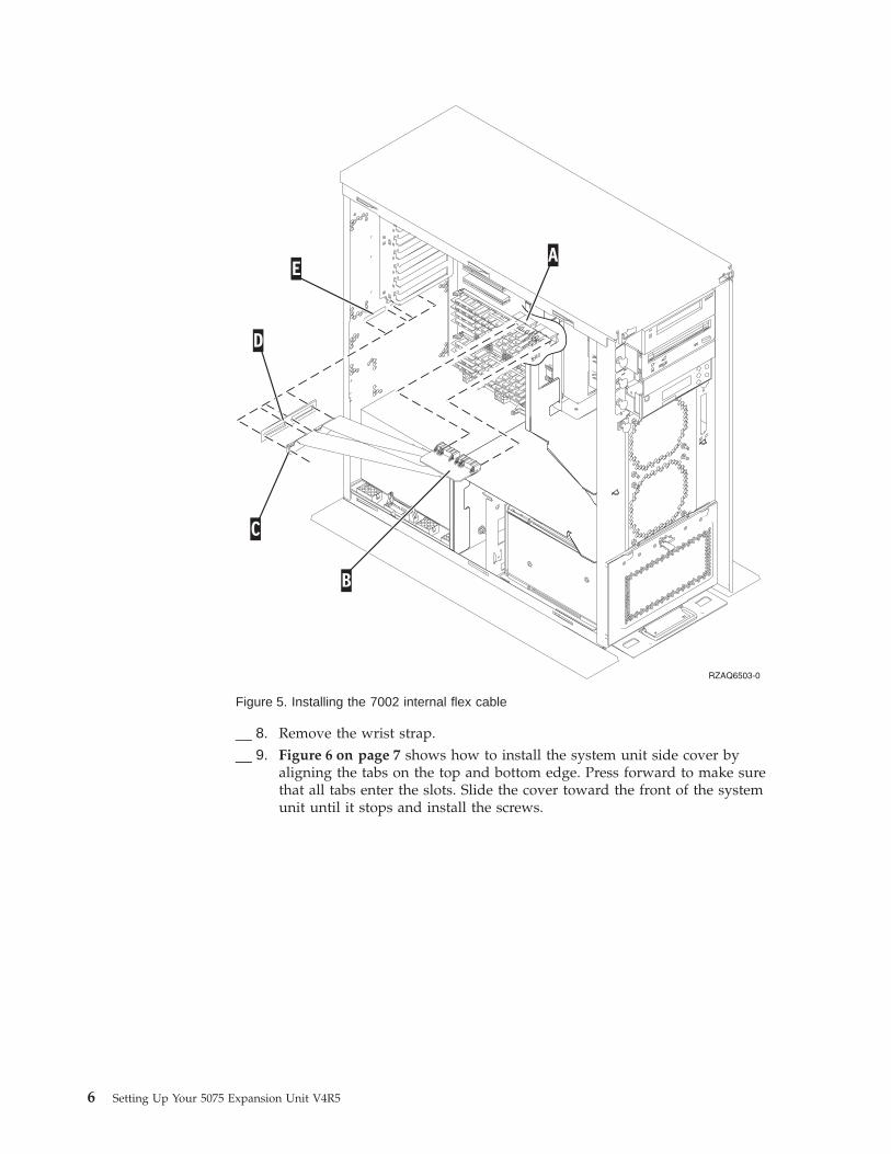
__ 8. Remove the wrist strap.__ 9. Figure 6 on page 7 shows how to install the system unit side cover by
aligning the tabs on the top and bottom edge. Press forward to make surethat all tabs enter the slots. Slide the cover toward the front of the systemunit until it stops and install the screws.
Figure 5. Installing the 7002 internal flex cable
6 Setting Up Your 5075 Expansion Unit V4R5

Chapter 2. Installing your 5075 directly to your system unit
This chapter describes how to install your 5075 directly to your AS/400 systemunit. If you are installing a 5075 in a loop with other expansion units, skip thischapter and go to “Chapter 3. Connecting your 5075 to another expansion unit” onpage 9.
Make sure that you have powered down your system unit before you begin. See“Powering down your system unit” on page 3 for instructions.
If you encounter difficulties during the installation, contact your authorized dealeror service provider.
Figure 6. Install system unit side cover
© Copyright IBM Corp. 2000 7
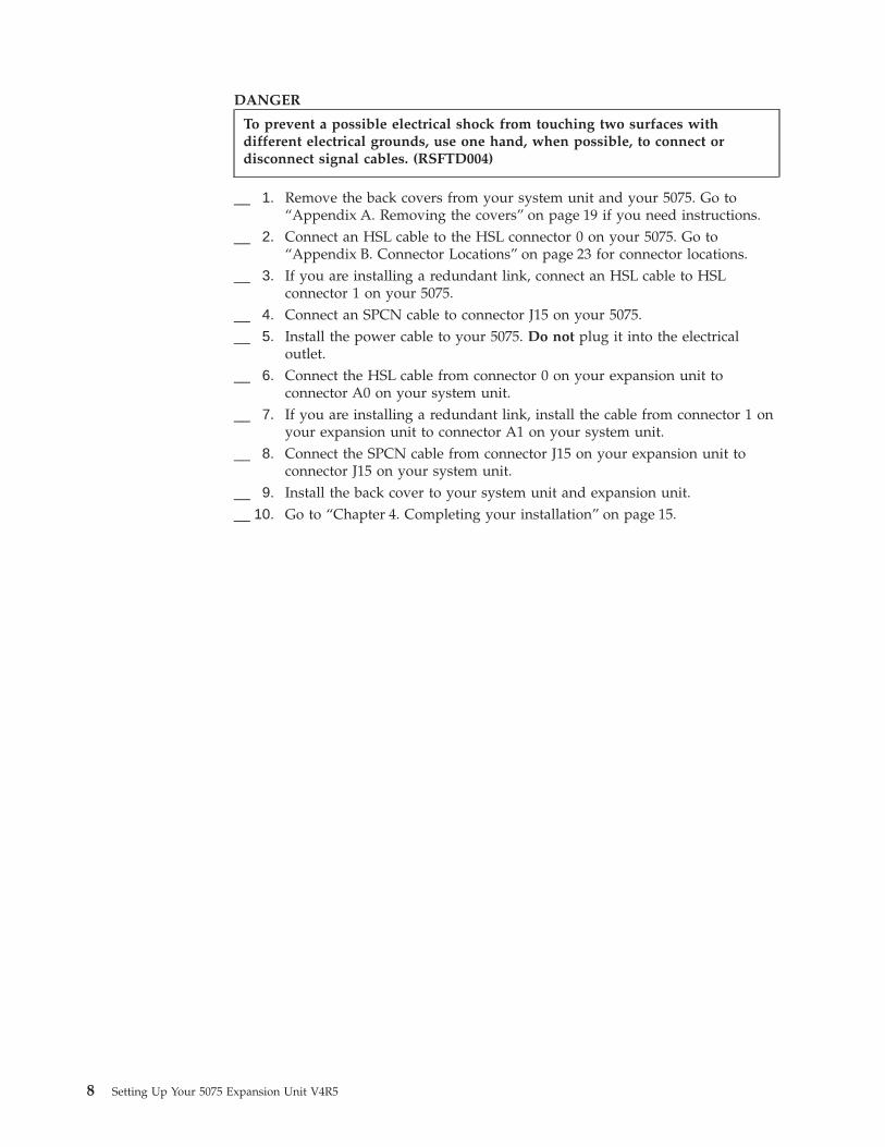
DANGER
To prevent a possible electrical shock from touching two surfaces withdifferent electrical grounds, use one hand, when possible, to connect ordisconnect signal cables. (RSFTD004)
__ 1. Remove the back covers from your system unit and your 5075. Go to“Appendix A. Removing the covers” on page 19 if you need instructions.
__ 2. Connect an HSL cable to the HSL connector 0 on your 5075. Go to“Appendix B. Connector Locations” on page 23 for connector locations.
__ 3. If you are installing a redundant link, connect an HSL cable to HSLconnector 1 on your 5075.
__ 4. Connect an SPCN cable to connector J15 on your 5075.__ 5. Install the power cable to your 5075. Do not plug it into the electrical
outlet.__ 6. Connect the HSL cable from connector 0 on your expansion unit to
connector A0 on your system unit.__ 7. If you are installing a redundant link, install the cable from connector 1 on
your expansion unit to connector A1 on your system unit.__ 8. Connect the SPCN cable from connector J15 on your expansion unit to
connector J15 on your system unit.__ 9. Install the back cover to your system unit and expansion unit.__ 10. Go to “Chapter 4. Completing your installation” on page 15.
8 Setting Up Your 5075 Expansion Unit V4R5

Chapter 3. Connecting your 5075 to another expansion unit
This section only applies to the AS/400e server 820. If your system unit is anAS/400e server 270, you can connect only one 5075. If your system unit is anAS/400e server 820, you can connect up to five expansion units in one loop. Thissection describes how to connect your 5075 expansion unit in a loop with otherexpansion units. You can only connect your 5075 with other expansion units thathave HSL hardware.
When you connect your 5075 to a loop, there are three possible locations in theloop that it can go. The procedures below contain instructions for the threepossible locations:v “Connecting your 5075 to the beginning of a loop”.v “Connecting your 5075 to the middle of a loop” on page 11.v “Connecting your 5075 to the end of a loop” on page 12.
Follow the procedure that best matches your system configuration.
Make sure that you have powered down your system unit before you begin. See“Powering down your system unit” on page 3 for instructions.
See “Appendix B. Connector Locations” on page 23 if you need help finding theconnectors on your expansion units or system unit.
If your 820 has a 503x Migration Unit connected to it, read “Appendix D. Cablingrules for systems with a 503x Migration Unit” on page 29 before you proceed.
If you encounter difficulties during the installation, contact your authorized dealeror service provider.
Connecting to a 503x migration unit
If your system unit has a 503x Migration Unit read “Appendix D. Cabling rules forsystems with a 503x Migration Unit” on page 29 before you proceed.
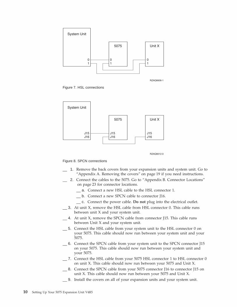
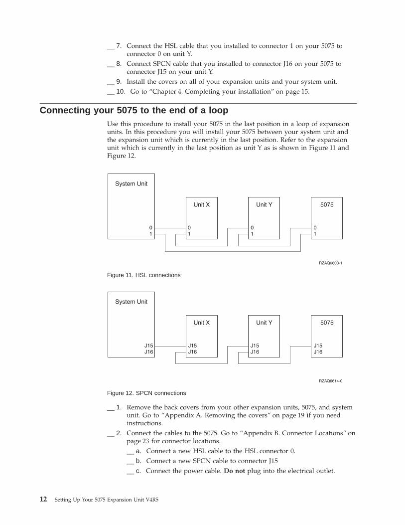
Connecting your 5075 to the beginning of a loopUse this procedure to connect your 5075 in the first position in a loop of expansionunits. In this procedure you will connect your 5075 between your system unit andthe expansion unit which is currently in the first position. These instructions referto the expansion unit which is currently in the first position as unit X as is shownin Figure 7 on page 10 and Figure 8 on page 10.
© Copyright IBM Corp. 2000 9
__ 1. Remove the back covers from your expansion units and system unit. Go to“Appendix A. Removing the covers” on page 19 if you need instructions.
__ 2. Connect the cables to the 5075. Go to “Appendix B. Connector Locations”on page 23 for connector locations.__ a. Connect a new HSL cable to the HSL connector 1.__ b. Connect a new SPCN cable to connector J16.__ c. Connect the power cable. Do not plug into the electrical outlet.
__ 3. At unit X, remove the HSL cable from HSL connector 0. This cable runsbetween unit X and your system unit.
__ 4. At unit X, remove the SPCN cable from connector J15. This cable runsbetween Unit X and your system unit.
__ 5. Connect the HSL cable from your system unit to the HSL connector 0 onyour 5075. This cable should now run between your system unit and your5075.
__ 6. Connect the SPCN cable from your system unit to the SPCN connector J15on your 5075. This cable should now run between your system unit andyour 5075.
__ 7. Connect the HSL cable from your 5075 HSL connector 1 to HSL connector 0on unit X. This cable should now run between your 5075 and Unit X.
__ 8. Connect the SPCN cable from your 5075 connector J16 to connector J15 onunit X. This cable should now run between your 5075 and Unit X.
__ 9. Install the covers on all of your expansion units and your system unit.
Figure 7. HSL connections
Figure 8. SPCN connections
10 Setting Up Your 5075 Expansion Unit V4R5

__ 10. Go to “Chapter 4. Completing your installation” on page 15
Connecting your 5075 to the middle of a loopUse this procedure if you are installing your 5075 in the middle of a loop. In otherwords, you are installing your 5075 between two other expansion units. Refer tothese expansion units as unit X and unit Y as is shown in Figure 9 and Figure 10.
__ 1. Remove the back covers from your other expansion units, 5075, and systemunit. Go to “Appendix A. Removing the covers” on page 19 if you needinstructions.
__ 2. At unit Y remove the SPCN cable from connector J15.__ 3. At unit Y remove the HSL cable from connector 0.__ 4. Connect the cables to your 5075. Go to “Appendix B. Connector Locations”
on page 23 for connector locations.__ a. Connect a new HSL cable to the HSL connector 1.__ b. Connect a new SPCN cable to connector J16.__ c. Connect the power cable. Do not plug into the electrical outlet.
__ 5. Connect the HSL cable from unit X to the HSL connector 0 on your 5075.This cable now runs between unit X and your 5075.
__ 6. Connect the SPCN cable from unit X to the SPCN connector J15 on your5075. This cable now runs between unit X and your 5075.
Figure 9. HSL connections
Figure 10. SPCN connections
Chapter 3. Connecting your 5075 to another expansion unit 11
__ 7. Connect the HSL cable that you installed to connector 1 on your 5075 toconnector 0 on unit Y.
__ 8. Connect SPCN cable that you installed to connector J16 on your 5075 toconnector J15 on your unit Y.
__ 9. Install the covers on all of your expansion units and your system unit.__ 10. Go to “Chapter 4. Completing your installation” on page 15.
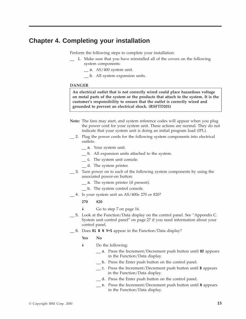
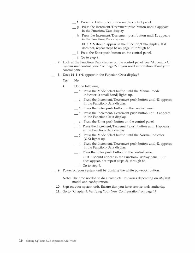
Connecting your 5075 to the end of a loopUse this procedure to install your 5075 in the last position in a loop of expansionunits. In this procedure you will install your 5075 between your system unit andthe expansion unit which is currently in the last position. Refer to the expansionunit which is currently in the last position as unit Y as is shown in Figure 11 andFigure 12.
__ 1. Remove the back covers from your other expansion units, 5075, and systemunit. Go to “Appendix A. Removing the covers” on page 19 if you needinstructions.
__ 2. Connect the cables to the 5075. Go to “Appendix B. Connector Locations” onpage 23 for connector locations.__ a. Connect a new HSL cable to the HSL connector 0.__ b. Connect a new SPCN cable to connector J15__ c. Connect the power cable. Do not plug into the electrical outlet.
Figure 11. HSL connections
Figure 12. SPCN connections
12 Setting Up Your 5075 Expansion Unit V4R5

__ 3. At unit Y, remove the HSL cable at connector 1. This cable currently runsbetween unit Y and your system unit.
__ 4. Connect the HSL cable from your 5075 HSL connector 0 to HSL connector 1on unit Y.
__ 5. Connect the SPCN cable from your 5075 connector J15 to connector J16 onunit Y.
__ 6. Install the covers on all of the expansion units and your system unit.__ 7. Go to “Chapter 4. Completing your installation” on page 15.
Chapter 3. Connecting your 5075 to another expansion unit 13

14 Setting Up Your 5075 Expansion Unit V4R5
Chapter 4. Completing your installation
Perform the following steps to complete your installation:__ 1. Make sure that you have reinstalled all of the covers on the following
system components:__ a. AS/400 system unit.__ b. All system expansion units.
DANGER
An electrical outlet that is not correctly wired could place hazardous voltageon metal parts of the system or the products that attach to the system. It is thecustomer’s responsibility to ensure that the outlet is correctly wired andgrounded to prevent an electrical shock. (RSFTD201)
Note: The fans may start, and system reference codes will appear when you plugthe power cord for your system unit. These actions are normal. They do notindicate that your system unit is doing an initial program load (IPL).
__ 2. Plug the power cords for the following system components into electricaloutlets:__ a. Your system unit.__ b. All expansion units attached to the system.__ c. The system unit console.__ d. The system printer.
__ 3. Turn power on to each of the following system components by using theassociated power-on button:__ a. The system printer (if present).__ b. The system control console.
__ 4. Is your system unit an AS/400e 270 or 820?
270 820
↓ Go to step 7 on page 16.__ 5. Look at the Function/Data display on the control panel. See “Appendix C.
System unit control panel” on page 27 if you need information about yourcontrol panel.
__ 6. Does 01 B N V=S appear in the Function/Data display?
Yes No
↓ Do the following:__ a. Press the Increment/Decrement push button until 02 appears
in the Function/Data display.__ b. Press the Enter push button on the control panel.__ c. Press the Increment/Decrement push button until B appears
in the Function/Data display.__ d. Press the Enter push button on the control panel.__ e. Press the Increment/Decrement push button until N appears
in the Function/Data display.
© Copyright IBM Corp. 2000 15
__ f. Press the Enter push button on the control panel.__ g. Press the Increment/Decrement push button until S appears
in the Function/Data display.__ h. Press the Increment/Decrement push button until 01 appears
in the Function/Data display.01 B N S should appear in the Function/Data display. If itdoes not, repeat steps 6a on page 15 through 6h.
__ i. Press the Enter push button on the control panel.__ j. Go to step 9.
__ 7. Look at the Function/Data display on the control panel. See “Appendix C.System unit control panel” on page 27 if you need information about yourcontrol panel.
__ 8. Does 01 B V=S appear in the Function/Data display?
Yes No
↓ Do the following:__ a. Press the Mode Select button until the Manual mode
indicator (a small hand) lights up.__ b. Press the Increment/Decrement push button until 02 appears
in the Function/Data display.__ c. Press the Enter push button on the control panel.__ d. Press the Increment/Decrement push button until B appears
in the Function/Data display.__ e. Press the Enter push button on the control panel.__ f. Press the Increment/Decrement push button until S appears
in the Function/Data display__ g. Press the Mode Select button until the Normal indicator
(OK) lights up.__ h. Press the Increment/Decrement push button until 01 appears
in the Function/Data display.__ i. Press the Enter push button on the control panel.
01 B S should appear in the Function/Display panel. If itdoes appear, not repeat steps 8a through 8h.
__ j. Go to step 9.__ 9. Power on your system unit by pushing the white power-on button.
Note: The time needed to do a complete IPL varies depending on AS/400model and configuration.
__ 10. Sign on your system unit. Ensure that you have service tools authority.__ 11. Go to “Chapter 5. Verifying Your New Configuration” on page 17.
16 Setting Up Your 5075 Expansion Unit V4R5
Chapter 5. Verifying Your New Configuration
Verify your new configuration by performing the following:__ 1. On an AS/400 command line, type:STRSST. Press the Enter key.__ 2. When the System Service Tools menu appears, select the Start a service tool
option.Press the Enter key.
__ 3. When the Start a Service Tool menu appears, select the Hardware servicemanager option.Press the Enter key.
__ 4. When the Hardware Service Manager menu appears, select the Packaginghardware resources (system, frames, cards...) option.Press the Enter key.Your new Expansion Unit appears on the list. Record the Frame ID andResource name here:___________, ___________. If your expansion unit doesnot appear, you need to verify your installation by performing these steps:__ a. Make sure that you powered on your 5075.__ b. Make sure that you installed the cables correctly. Refer to “Chapter 2.
Installing your 5075 directly to your system unit” on page 7 or“Chapter 3. Connecting your 5075 to another expansion unit” onpage 9.
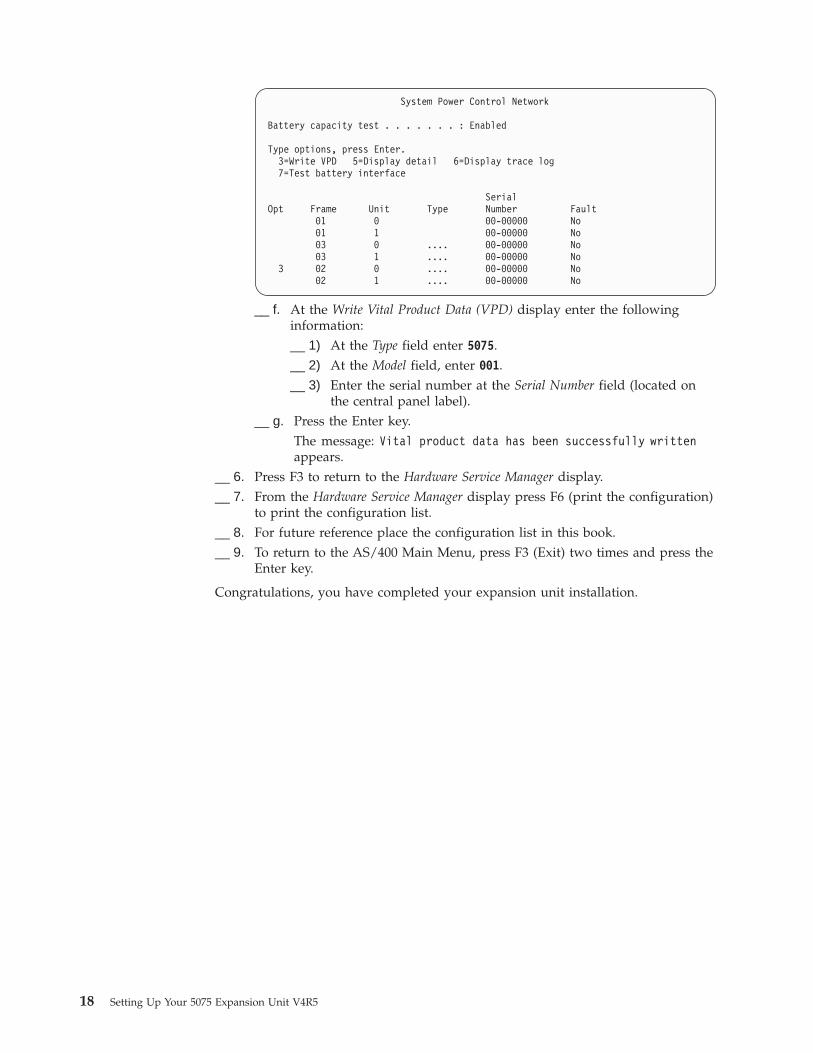
__ 5. You need to update vital product data (VPD) for your new 5075:__ a. Press F3 to return to the Hardware Service Manager display.__ b. At the Hardware Service Manager display, select the System power
control network (SPCN).__ c. Press the Enter key twice.__ d. Locate your expansion unit on the System Power Control Network
display by Frame ID.__ e. Enter a 3 (Write VPD) for the Frame ID with a 0 in the Unit field as is
shown in the example below. Press Enter.
Example: If the Frame ID for your expansion unit is 2, put the cursor infront of the 02. Then enter a 3 (Write VPD), as is shown in theexample below. Use the Frame ID with a 0 in the Unit field.
© Copyright IBM Corp. 2000 17
System Power Control Network
Battery capacity test . . . . . . . : Enabled
Type options, press Enter.3=Write VPD 5=Display detail 6=Display trace log7=Test battery interface
SerialOpt Frame Unit Type Number Fault
01 0 00-00000 No01 1 00-00000 No03 0 .... 00-00000 No03 1 .... 00-00000 No
3 02 0 .... 00-00000 No02 1 .... 00-00000 No
__ f. At the Write Vital Product Data (VPD) display enter the followinginformation:__ 1) At the Type field enter 5075.__ 2) At the Model field, enter 001.__ 3) Enter the serial number at the Serial Number field (located on
the central panel label).__ g. Press the Enter key.
The message: Vital product data has been successfully writtenappears.
__ 6. Press F3 to return to the Hardware Service Manager display.__ 7. From the Hardware Service Manager display press F6 (print the configuration)
to print the configuration list.__ 8. For future reference place the configuration list in this book.__ 9. To return to the AS/400 Main Menu, press F3 (Exit) two times and press the
Enter key.
Congratulations, you have completed your expansion unit installation.
18 Setting Up Your 5075 Expansion Unit V4R5
Appendix A. Removing the covers
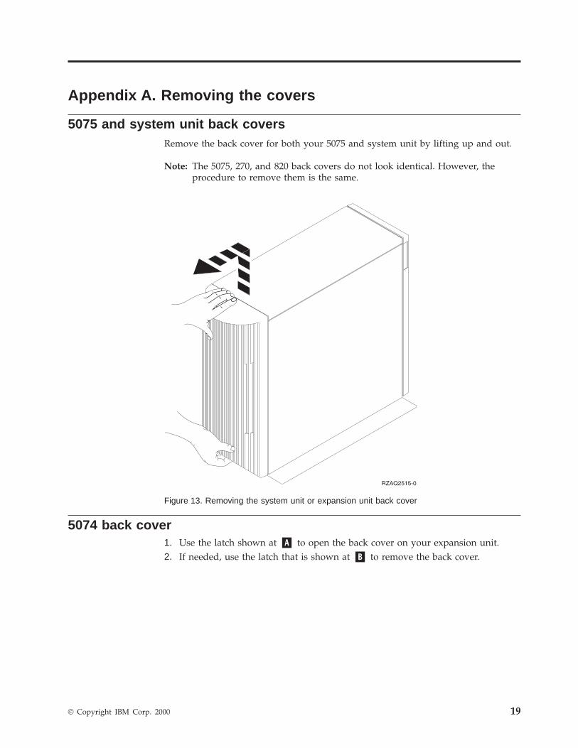
5075 and system unit back coversRemove the back cover for both your 5075 and system unit by lifting up and out.
Note: The 5075, 270, and 820 back covers do not look identical. However, theprocedure to remove them is the same.
5074 back cover1. Use the latch shown at �A� to open the back cover on your expansion unit.2. If needed, use the latch that is shown at �B� to remove the back cover.
Figure 13. Removing the system unit or expansion unit back cover
© Copyright IBM Corp. 2000 19
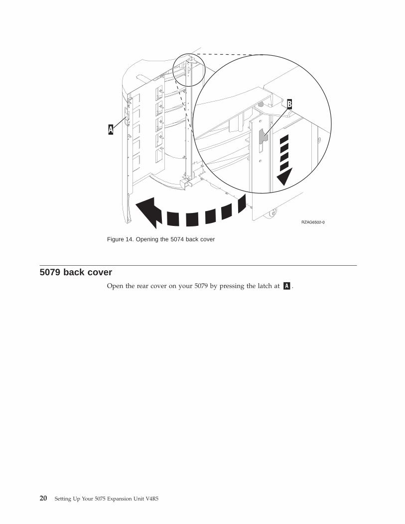
5079 back coverOpen the rear cover on your 5079 by pressing the latch at �A�.
Figure 14. Opening the 5074 back cover
20 Setting Up Your 5075 Expansion Unit V4R5
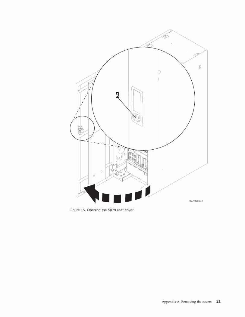
Figure 15. Opening the 5079 rear cover
Appendix A. Removing the covers 21

22 Setting Up Your 5075 Expansion Unit V4R5
Appendix B. Connector Locations
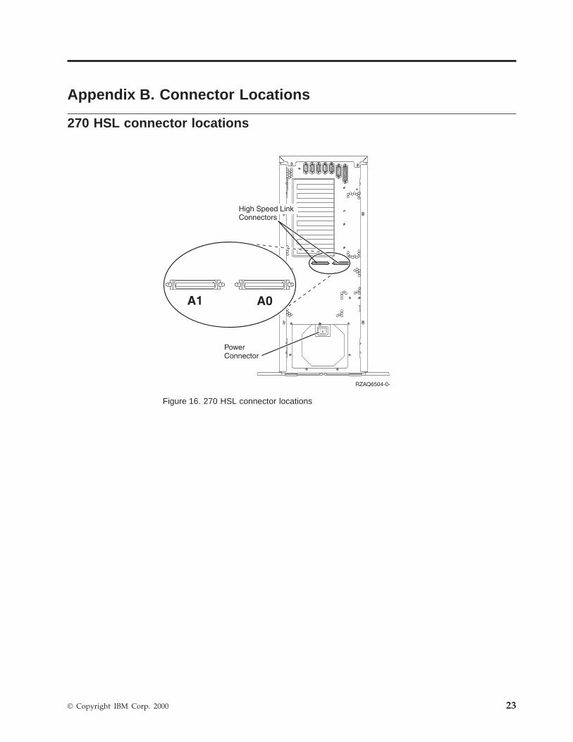
270 HSL connector locations
Figure 16. 270 HSL connector locations
© Copyright IBM Corp. 2000 23
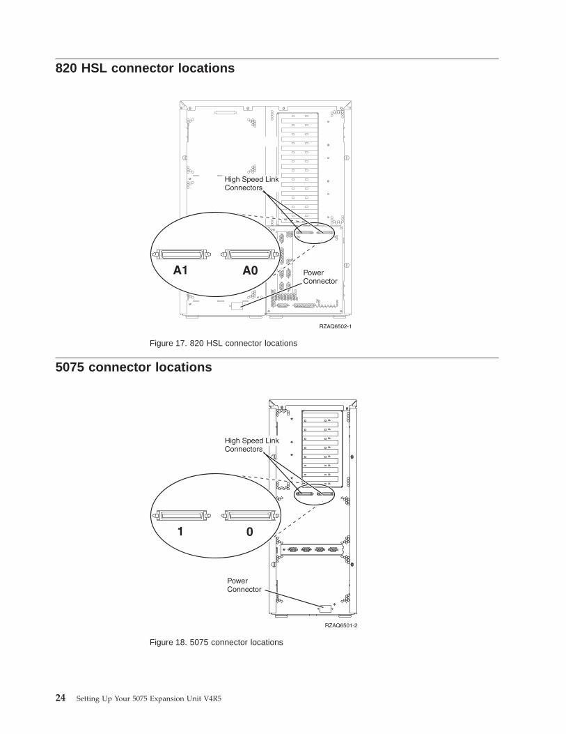
820 HSL connector locations
5075 connector locations
Figure 17. 820 HSL connector locations
Figure 18. 5075 connector locations
24 Setting Up Your 5075 Expansion Unit V4R5
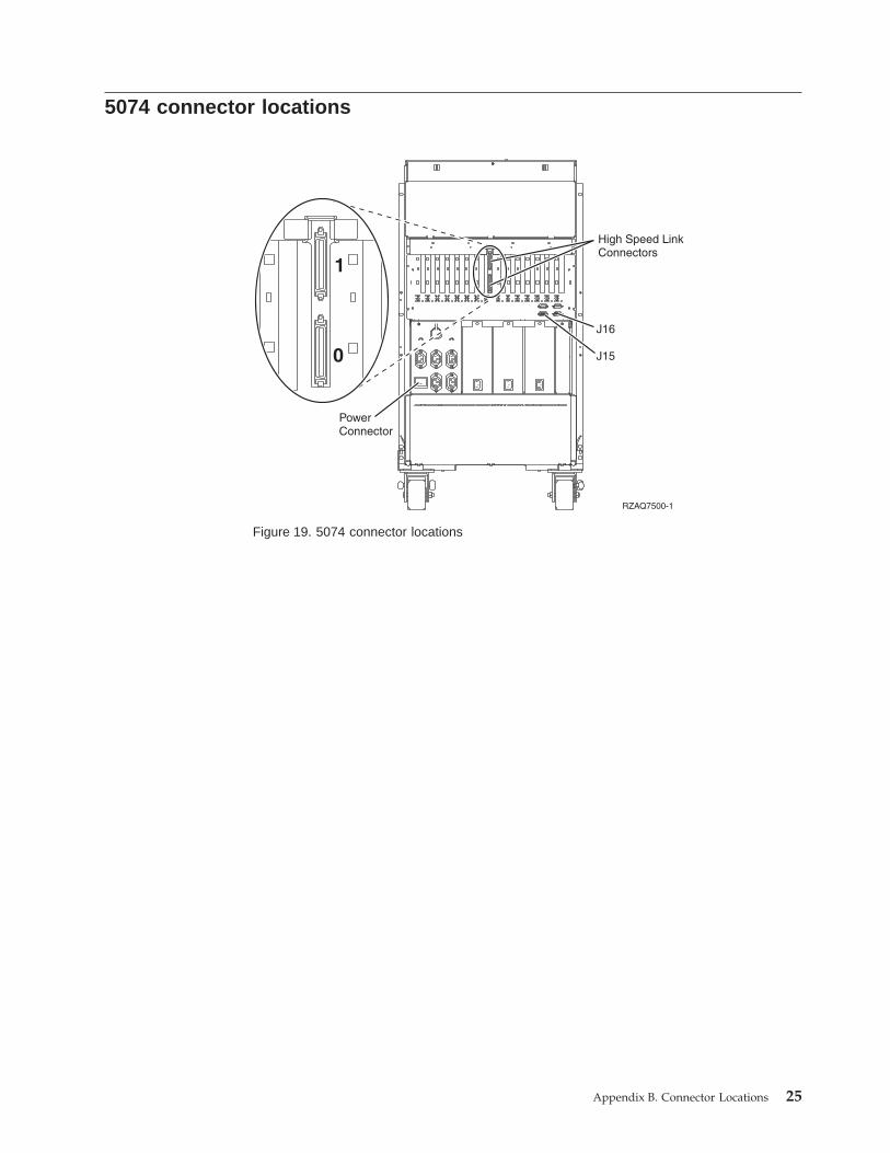
5074 connector locations
Figure 19. 5074 connector locations
Appendix B. Connector Locations 25
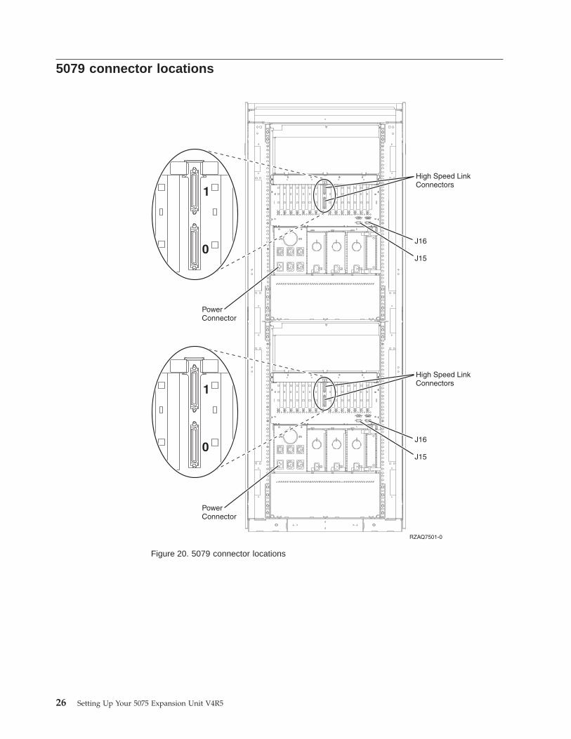
5079 connector locations
Figure 20. 5079 connector locations
26 Setting Up Your 5075 Expansion Unit V4R5
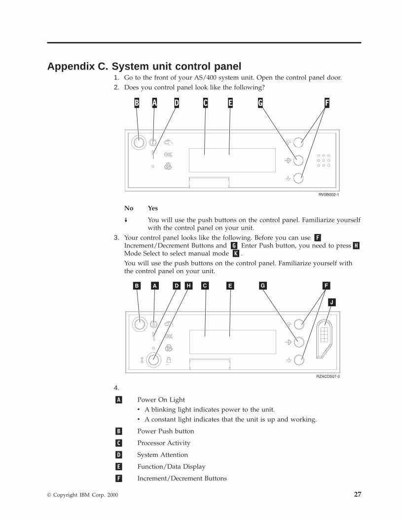
Appendix C. System unit control panel1. Go to the front of your AS/400 system unit. Open the control panel door.2. Does you control panel look like the following?
No Yes
↓ You will use the push buttons on the control panel. Familiarize yourselfwith the control panel on your unit.
3. Your control panel looks like the following. Before you can use �F�Increment/Decrement Buttons and �G� Enter Push button, you need to press�H�Mode Select to select manual mode �K�.You will use the push buttons on the control panel. Familiarize yourself withthe control panel on your unit.
4.
�A� Power On Lightv A blinking light indicates power to the unit.v A constant light indicates that the unit is up and working.
�B� Power Push button
�C� Processor Activity
�D� System Attention
�E� Function/Data Display
�F� Increment/Decrement Buttons
© Copyright IBM Corp. 2000 27

�G� Enter Push button
�H� Mode Select
�J� Electronic Keystick Slot
28 Setting Up Your 5075 Expansion Unit V4R5
Appendix D. Cabling rules for systems with a 503x MigrationUnit
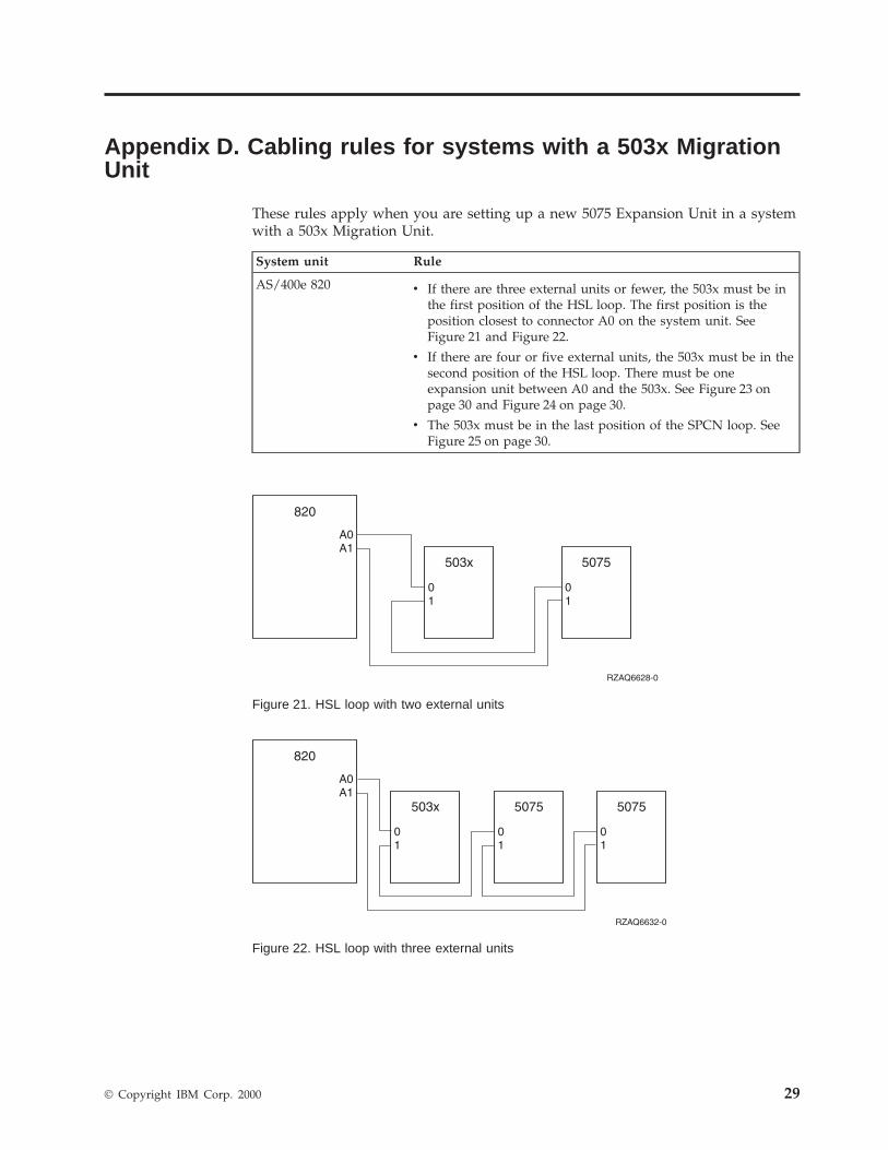
These rules apply when you are setting up a new 5075 Expansion Unit in a systemwith a 503x Migration Unit.
System unit Rule
AS/400e 820 v If there are three external units or fewer, the 503x must be inthe first position of the HSL loop. The first position is theposition closest to connector A0 on the system unit. SeeFigure 21 and Figure 22.
v If there are four or five external units, the 503x must be in thesecond position of the HSL loop. There must be oneexpansion unit between A0 and the 503x. See Figure 23 onpage 30 and Figure 24 on page 30.
v The 503x must be in the last position of the SPCN loop. SeeFigure 25 on page 30.
Figure 21. HSL loop with two external units
Figure 22. HSL loop with three external units
© Copyright IBM Corp. 2000 29

Figure 23. HSL loop with four external units
Figure 24. HSL loop with five external units
Figure 25. SPCN loop with 503x
30 Setting Up Your 5075 Expansion Unit V4R5
Notices
This information was developed for products and services offered in the U.S.A.IBM may not offer the products, services, or features discussed in this document inother countries. Consult your local IBM representative for information on theproducts and services currently available in your area. Any reference to an IBMproduct, program, or service is not intended to state or imply that only that IBMproduct, program, or service may be used. Any functionally equivalent product,program, or service that does not infringe any IBM intellectual property right maybe used instead. However, it is the user’s responsibility to evaluate and verify theoperation of any non-IBM product, program, or service.
IBM may have patents or pending patent applications covering subject matterdescribed in this document. The furnishing of this document does not give youany license to these patents. You can send license inquiries, in writing, to thefollowing address:
IBM Director of LicensingIBM Corporation500 Columbus AvenueThornwood, NY 10594U.S.A.
For license inquiries regarding double-byte (DBCS) information, contact the IBMIntellectual Property Department in your country or send inquiries, in writing, to:
IBM World Trade Asia CorporationLicensing2-31 Roppongi 3-chome, Minato-kuTokyo 106, Japan
The following paragraph does not apply to the United Kingdom or any othercountry where such provisions are inconsistent with local law:INTERNATIONAL BUSINESS MACHINES CORPORATION PROVIDES THISPUBLICATION “AS IS” WITHOUT WARRANTY OF ANY KIND, EITHEREXPRESS OR IMPLIED, INCLUDING, BUT NOT LIMITED TO, THE IMPLIEDWARRANTIES OF NON-INFRINGEMENT, MERCHANTABILITY OR FITNESSFOR A PARTICULAR PURPOSE. Some states do not allow disclaimer of express orimplied warranties in certain transactions, therefore, this statement may not applyto you.
This information could include technical inaccuracies or typographical errors.Changes are periodically made to the information herein; these changes will beincorporated in new editions of the publication. IBM may make improvementsand/or changes in the product(s) and/or the program(s) described in thispublication at any time without notice.
Information concerning non-IBM products was obtained from the suppliers ofthose products, their published announcements or other publicly available sources.IBM has not tested those products and cannot confirm the accuracy ofperformance, compatibility or any other claims related to non-IBM products.Questions on the capabilities of non-IBM products should be addressed to thesuppliers of those products.
© Copyright IBM Corp. 2000 31
If you are viewing this information softcopy, the photographs and colorillustrations may not appear.
The drawings and specifications contained herein shall not be reproduced in wholeor in part without the written permission of IBM.
IBM has prepared this publication for use by customer personnel for operating andplanning for the specific machines indicated. IBM makes no representations that itis suitable for any other purpose.
Electronic Emission Notices
Federal Communications Commission (FCC) StatementNote: This equipment has been tested and found to comply with the limits for aClass A digital device, pursuant to Part 15 of the FCC Rules. These limits aredesigned to provide reasonable protection against harmful interference when theequipment is operated in a commercial environment. This equipment generates,uses, and can radiate radio frequency energy and, if not installed and used inaccordance with the instruction manual, may cause harmful interference to radiocommunications. Operation of this equipment in a residential area is likely to causeharmful interference, in which case the user will be required to correct theinterference at his own expense.
Properly shielded and grounded cables and connectors must be used in order tomeet FCC emission limits. IBM is not responsible for any radio or televisioninterference caused by using other than recommended cables and connectors or byunauthorized changes or modifications to this equipment. Unauthorized changesor modifications could void the user’s authority to operate the equipment.
This device complies with Part 15 of the FCC rules. Operation is subject to thefollowing two conditions: (1) this device may not cause harmful interference, and(2) this device must accept any interference received, including interference thatmay cause undesired operation.
Responsible Party:
International Business Machines CorporationNew Orchard RoadArmonk, NY 10504
Telephone: 1-919-543-2193
Industry Canada Compliance Statement
This Class A digital apparatus meets the requirements of the CanadianInterference-Causing Equipment Regulations.
Avis de conformité à la réglementation d’Industrie Canada
Cet appareil numérique de la classe A respecte toutes les exigences du Règlementsur le matériel brouilleur du Canada.
European Community Compliance Statement
32 Setting Up Your 5075 Expansion Unit V4R5
This product is in conformity with the protection requirements of EU CouncilDirective 89/336/EEC on the approximation of the laws of the Member Statesrelating to electromagnetic compatibility. IBM cannot accept responsibility for anyfailure to satisfy the protection requirements resulting from a non-recommendedmodification of the product, including the fitting of non-IBM option cards.
Australia and New Zealand Class A Statement
Attention: This is a Class A product. In a domestic environment this product maycause radio interference in which case the user may be required to take adequatemeasures.
TrademarksThe following terms are trademarks of the International Business MachineCorporation in the United States, or other countries, or both:
AS/400AS/400e seriesIBMOS/400PowerPC
Java is a registered trademark of Sun Microsystems, Inc.
Other company, product, and service names, may be trademarks or service marksof others.
Notices 33

34 Setting Up Your 5075 Expansion Unit V4R5
Readers’ Comments — We’d Like to Hear from You
AS/400eSetting Up Your 5075 Expansion Unit
Publication No. SA41-5148-00
Overall, how satisfied are you with the information in this book?
Very Satisfied Satisfied Neutral Dissatisfied VeryDissatisfied
Overall satisfaction h h h h h
How satisfied are you that the information in this book is:
Very Satisfied Satisfied Neutral Dissatisfied VeryDissatisfied
Accurate h h h h h
Complete h h h h h
Easy to find h h h h h
Easy to understand h h h h h
Well organized h h h h h
Applicable to your tasks h h h h h
Please tell us how we can improve this book:
Thank you for your responses. May we contact you? h Yes h No
When you send comments to IBM, you grant IBM a nonexclusive right to use or distribute your comments in anyway it believes appropriate without incurring any obligation to you.
Name Address
Company or Organization
Phone No.
Readers’ Comments — We’d Like to Hear from YouSA41-5148-00
SA41-5148-00
����Cut or FoldAlong Line
Cut or FoldAlong Line
Fold and Tape Please do not staple Fold and Tape
Fold and Tape Please do not staple Fold and Tape
NO POSTAGENECESSARYIF MAILED IN THEUNITED STATES
BUSINESS REPLY MAILFIRST-CLASS MAIL PERMIT NO. 40 ARMONK, NEW YORK
POSTAGE WILL BE PAID BY ADDRESSEE
IBM CORPORATIONATTN DEPT 542 IDCLERK3605 HWY 52 NROCHESTER MN 55901-7829
_ _ _ _ _ _ _ _ _ _ _ _ _ _ _ _ _ _ _ _ _ _ _ _ _ _ _ _ _ _ _ _ _ _ _ _ _ _ _ _ _ _ _ _ _ _ _ _ _ _ _ _ _ _ _ _ _ _ _ _ _ _ _ _ _ _ _ _ _ _ _ _ _ _ _ _ _ _ _ _ _ _ _ _ _ _ _ _ _
_ _ _ _ _ _ _ _ _ _ _ _ _ _ _ _ _ _ _ _ _ _ _ _ _ _ _ _ _ _ _ _ _ _ _ _ _ _ _ _ _ _ _ _ _ _ _ _ _ _ _ _ _ _ _ _ _ _ _ _ _ _ _ _ _ _ _ _ _ _ _ _ _ _ _ _ _ _ _ _ _ _ _ _ _ _ _ _ _
__
__
__
__
__
__
__
__
__
__
__
__
__
__
__
__
__
__
__
__
__
__
__
__
__
__
__
__
__
__
__
__
__
__
__
__
__
__
__
__
__
__
__
__
__
__
__
__
__
_


����
Printed in the United States of Americaon recycled paper containing 10%recovered post-consumer fiber.
SA41-5148-00
Spin
ein
form
atio
n:
��
�A
S/40
0eSe
tting
Up
Your
5075
Exp
ansio
nU
nitV
4R5
Vers
ion
4