Embed Size (px)
Citation preview

Series 8345 4.5-Meter Prime Focus Motorized Antenna
Installation Manual
Manual 42S199F March 2003

Table of Contents
Table of Contents
Table of Contents .................................................................................................. iii
List of Figures ......................................................................................................... v
List of Tables .......................................................................................................... vi
Safety Summary ................................................................................................... vii
General Information ........................................................................................... 1-1
1.1 Introduction .............................................................................................................1-1
1.2 Description ...............................................................................................................1-1
1.3 Stability During High Winds.................................................................................1-2
2.1 General......................................................................................................................2-1
2.2 What to do About Visible Loss or Damage .........................................................2-1
2.3 What to do About Concealed Damage ................................................................2-1
2.4 How to Inventory Equipment Received ..............................................................2-2
2.5 How To Return Equipment ...................................................................................2-2
2.6 General Mechanical Safety Summary ..................................................................2-3
2.6.1 Emergency Plan.......................................................................................................2-3
2.7 General Electrical Safety Summary ......................................................................2-4
2.7.1 Resuscitation ............................................................................................................2-4
2.8 Recommended Tools And Equipment.................................................................2-5
2.9 Recommended Installation Sequence...................................................................2-6
2.10 Recommended Torque Values ..............................................................................2-6
2.11 Assembly of Mount.................................................................................................2-8
2.11.1 Adjustment of Eccentric Cam Followers ...........................................................2-21
2.11.2 Installation of Azimuth Actuator........................................................................2-21
2.11.3 Installation of Azimuth Stabilizer Assembly ....................................................2-22
2.11.4 Installation of Elevation Actuator.......................................................................2-22
2.11.5 Installation of Hub Support Brackets .................................................................2-23
2.12 ASSEMBLY OF REFLECTOR..............................................................................2-25
42S199F iii

Table of Contents
2.12.1 Installation of Feed................................................................................................2-32
2.12.2 Installation of C-Band Feed .................................................................................2-32
2.12.3 Installation of Ku-Band Feed...............................................................................2-38
2.13 Technical Drawings ..............................................................................................2-43
Operation.............................................................................................................. 3-1
3.1 General......................................................................................................................3-1
3.2 Satellite Pointing Procedure ..................................................................................3-1
3.3 Focal Length Inspection And Adjustment...........................................................3-1
3.3.1 Adjustment Procedure ...........................................................................................3-2
3.4 Equipment Required For Transmit Patterns .......................................................3-3
Maintenance......................................................................................................... 4-1
4.1 General......................................................................................................................4-1
4.2 Periodic Maintenance .............................................................................................4-1
4.2.1 Weekly Maintenance ..............................................................................................4-1
4.2.2 Monthly Maintenance ............................................................................................4-2
4.2.3 Bi-Monthly Maintenance........................................................................................4-2
4.2.4 Yearly Maintenance ................................................................................................4-4
4.3 Corrosion Protection...............................................................................................4-5
42S199F iv

Table of Contents
LIST OF FIGURES
Figure 2-1. Installation of Leg Assemblies..........................................................................................2-9
Figure 2-2. Installation of Leg Support Bracket ...............................................................................2-11
Figure 2-3. Installation of Support Arms ..........................................................................................2-12
Figure 2-4. Installation of Azimuth Ring ..........................................................................................2-13
Figure 2-5. Tightening Sequence for Pedestal..................................................................................2-14
Figure 2-6. AZ/EL Assembly, 4.5 Meter Motorized (Sheet 1 of 5), 482045B ...............................2-16
Figure 2-7. Assembly and Adjustment of Rib and Panel Brace.....................................................2-26
Figure 2-8. Template Installation .......................................................................................................2-27
Figure 2-9. Tapered Pins .....................................................................................................................2-28
Figure 2-10. Placing the Template onto the Panel ...........................................................................2-30
Figure 2-11A. Stringing the Reflector ...................................................................................2-30
Figure 2-11B. Locating the Strings for Rib Adjustment ..................................................................2-30
Figure 2-12. Feed and Feed Housing Assembly (C-Band) .............................................................2-33
Figure 2-13. Attachment of Spars to Support Brackets...................................................................2-33
Figure 2-14. Installation of Feed Housing and Orthomode Transducer ......................................2-34
Figure 2-15. Installation of LNAs/LNBs ..........................................................................................2-36
Figure 2-16. Installation of LNA/LNB Cover ..................................................................................2-37
Figure 2-17. Feed Window Installation.............................................................................................2-39
Figure 2-18. Feed and Feed Housing Assembly (Ku-Band)...........................................................2-40
Figure 2-19. Attachment of Spars to Support Brackets...................................................................2-40
Figure 2-20. Installation of Feed Housing, OMT and LNAs/LNBs..............................................2-41
Figure 2-21. Installation of LNA/LNB Cover ..................................................................................2-42
Figure 2-22. Motorized 4.5-Meter Ku-Band Feed Installation (Sheet 1 of 3), 367733 .................2-44
Figure 2-23. Motorized 4.5-Meter Ku-Band Feed Assembly (Sheet 1 of 10), 367730..................2-47
Figure 3-1. Focal Length Inspection and Adjustment.......................................................................3-2
42S199F v

Table of Contents
LIST OF TABLES
Table 2-1. Tools and Equipment Required For Installation .............................................................2-5
Table 2-2. Torque Values For Antenna Fasteners (High Strength Grade 5 Zinc or Galvanized Steel)..................................................................................................................................................2-6
Table 2-3. Torque Values For Antenna Fasteners (Stainless Steel) .................................................2-7
42S199F vi

Safety Summary
SAFETY SUMMARY
Notice Any service, adjustment, maintenance, or repair of this product must be performed only by authorized technical service personnel.
Prior to installation and use of this product review all safety markings and instructions. When safety precautions or important information is presented in this manual, the information will normally be presented just prior to the point where the hazard is likely to be encountered.
The following symbols are used throughout this manual to bring attention to practices, procedures, and conditions important to the safety of the operator and equipment or to obtaining desirable results from the equipment.
This symbol warns of electrical shock hazards to personnel. Failure to comply with the instructions of such a warning may result in severe injury or death resulting from electrical shock.
This symbol warns of non-electrical hazards to personnel. Failure to comply with the instructions of such a warning may result in severe injury or death.
This symbol warns of hazards to equipment. Failure to comply with the instructions of such a caution may result in damage or destruction of equipment.
This symbol is used to bring attention to installation grounding requirements.
NOTE Notes are used to provide clarification, or to alert the reader of possible erroneous results, which may occur if a procedure is not followed as written.
42S199F vii

Notice
All Rights Reserved
The information contained in this document is proprietary to ViaSat, Inc. This document may not be reproduced or distributed in any form without the consent of ViaSat, Inc. The information in this document is subject to change without notice. ViaSat, Inc. assumes no responsibility for any errors that may appear in this document and does not warranty any specific application. Any product names mentioned herein are used for identification purposes only, and may be trademarks and/or registered trademarks of their respective companies. In all correspondence with ViaSat, Inc. regarding this publication, please refer to the Manual Part No. on the title page. Copyright ® 2003 ViaSat, Inc. All rights reserved. No part of this book may be reproduced in any form or by any means without permission in writing from ViaSat, Inc.

Blank Page

Chapter 1 - General Information
Chapter 1
General Information
1.1 Introduction
This manual contains information needed to properly install, operate, and maintain the Series 8345 4.5-meter (4.5M) Prime Focus Motorized Antenna. Section 1 contains general information on the Series 8345M Prime Focus Motorized Antenna. Chapters 2 through 4 contain information pertaining to Series 8345 4.5M Prime Focus Motorized Antenna installation, operation, and maintenance. All warnings and cautions should be reviewed before any procedures are performed. Failure to do so may result in personal injury or equipment damage.
1.2 Description
The Series 8345 4.5M Prime Focus Motorized Antenna is designed for quick and easy installation and provides cost effective, high performance for a wide range of applications combining the following features:
• Ease of Installation
• Minimum maintenance design
• Minimum shipping and installation costs design
• Minimum site preparation requirements
• Full satellite arc coverage from any location in the contiguous United States (2° to 90° continuous elevation: 180° continuous azimuth)
• Elevation-over-azimuth Mount for ease of operation
• Interchangeable stamped reflector panels for consistent surface accuracy
• Protected environment for LNAs/LNBs
• Ku-band compatible
The motorized elevation-over-azimuth mount provides the 4.5-meter antenna with ease of operation and high pointing accuracy. The mount provides continuous pointing satellite arc coverage from any location in the United States. Pointing of the antenna is rapid and accurate. 2° to 90° continuous elevation is provided for maximum pointing capability. 360° in 3 overlapping 180° continuous sectors precludes alignment of the foundation
42S199F 1-1
Chapter 1 - General Information
to a specific heading, thereby eliminating the possibility of installation errors associated with foundation centerlines.
The parabolic reflector consists of twelve precision stretch stamped steel panels for consistent surface accuracy. The twelve panels are uniform and completely interchangeable, resulting in handling convenience, lower shipping costs and easy installation. Once a foundation has been prepared, three people can install the antenna in one day.
NOTE
The mount load frame weight is approximately 250 lbs. A minimum of three people shall be used to manually place the load frame on the azimuth ring. An optional hoisting device may also be used during installation.
Each of the optional feeds offered with the Series 8345 4.5M Prime Focus Motorized Antenna provides consistent high quality and unusual economy in a mid-sized antenna system. The Ku-band feed provides dual polarization, receive only capability in the 10.9 to 12.75 GHz range. The C-band feed provides dual polarization, receive-only capability in the 3.7 to 4.2 GHz range. Both are available in motorized polarization versions. Also available are Ku-band receive-transmit versions.
1.3 Stability During High Winds
The reflector mount and motorized actuators are designed to withstand high winds. The azimuth and elevation actuators will drive the antenna in an 85 mi/hr wind at any orientation with no ice.
The antenna will survive 110 mi/hr winds at any orientation with no ice. Antenna survival at 125 mi/hr winds from any direction with no ice is also achievable by driving the elevation axis to a 90° stow position.
42S199F 1-2

Chapter 2 - Installation
Chapter 2
Installation
2.1 General
This chapter contains procedures for unpacking and installing the Series 8345 4.5M Prime Focus Motorized Antenna. General safety precautions and procedures are also described.
ViaSat thoroughly inspects and carefully packs all equipment before shipment. At the time of shipment, the carrier assumes responsibility for its safe delivery; therefore, do not return damaged units to ViaSat. Instead, file a claim with the carrier as noted in the paragraphs following the initial unpacking procedure given below:
1. Inspect shipping carton for visible damage.
2. Open the shipping carton.
3. Remove all packing material.
4. Inspect unit for visible damage.
5. Using packing list, check for missing items (see "How To Inventory Equipment Received" below).
2.2 What to do About Visible Loss or Damage
Make a note of any loss or evidence of external damage on the freight bill or receipt, and have it signed by the carrier's agent. Failure to adequately describe such external evidence of loss or damage may result in the carrier refusing to honor a damage claim. The form required to file such a claim will be supplied by the carrier.
2.3 What to do About Concealed Damage
Concealed damage means damage which does not become apparent until the unit has been unpacked. The contents may be damaged in transit due to rough handling, even though the carton may not show external damage. If you discover damage after unpacking the unit, make a written request for inspection by the carrier's agent within 15 days of the delivery date, then file a claim with the carrier since such damage is the carrier's responsibility. If you follow these instructions carefully, ViaSat guarantees its full support of your claims to protect you against loss from concealed damage.
42S199F 2-1

Chapter 2 - Installation
2.4 How to Inventory Equipment Received
Check off each item received against that list on the packing slip included with the shipment, and verify that this list matches the purchase order. If any items are missing, please notify ViaSat immediately.
2.5 How To Return Equipment
ViaSat's Satellite Ground Systems division makes every reasonable effort to ensure that all items arrive safely and in working order. When equipment is received, which is not in working order, return the equipment to the factory for repair or replacement. Return the equipment according to the following procedure. This procedure will apply whenever equipment is returned for warranty or other services.
a) Notify ViaSat of the problem and request a Return Material Authorization (RMA) number and shipping instructions.
For a current list of telephone and email contact information please refer to the Contact Information section of the ViaSat internet site (http://www.viasat.com). Select Products and Technologies, Satellite Ground Systems and Contact Us.
b) Tag or identify defective equipment and note defect and circumstances, if any. If known, reference sales order, purchase order, and date equipment was received.
c) Reship equipment in original shipping container or use a strong shipping container to protect equipment during shipment.
d) Package equipment using shock-absorbing material around all sides of equipment.
e) Seal container securely and mark outside of container FRAGILE.
WARNING
Electrical shock from voltages used in this system can cause injury or death. Prior to making any electrical connections or performing maintenance and repair, ensure power is removed. Electrical connections should be made only by qualified personnel in accordance with local regulation.
42S199F 2-2

Chapter 2 - Installation
2.6 General Mechanical Safety Summary
These are general mechanical safety precautions that are not related to any specific procedure. They are recommended precautions that personnel must understand and apply.
WARNING
Installation or maintenance of antennas may require persons to work at elevated work stations. Whenever persons are working at eight or more feet above ground and not on a guarded platform, they should wear safety belts with at least one, and preferably two, lanyards, with the exception that trained and qualified persons may work up to 25 feet if on an approved ladder. In the sentence above, approved usually means that the ladder is tied off once the person has climbed but before work begins.
WARNING
Overhead hazards, either because items may fall or because a person may strike them unintentionally, are typical around construction sites or during installation of large antennas. It is prudent to adopt the following rules:
1. Never stand underneath anything while it is being hoisted.
2. Always wear a hard hat, especially if someone is above you.
WARNING
Ensure that all electrical tools and equipment are properly grounded.
2.6.1 Emergency Plan
Have an emergency plan. Know the procedures for obtaining first-aid and fire-fighting assistance. Plan your work and maintain good housekeeping; the safety and quality of the product are at stake.
42S199F 2-3

Chapter 2 - Installation
2.7 General Electrical Safety Summary
These are general electrical safety precautions that are not related to any specific procedure. These are recommended precautions that personnel must understand and apply.
WARNING
Avoid shorting circuits when using metal tools. Some circuits have high current capability which, when shorted, will flash and may cause burns and/or eye injury.
Remove all jewelry and exposed metal objects from body and clothing before performing maintenance, adjustments, and/or troubleshooting. Before working inside the equipment, remove all power, unless power is required to perform procedures. Do not replace parts with power on.
Replacement of fuses or other parts must be done using identical types and ratings. Substitution of non-identical parts may cause safety and fire hazards.
Servicing this equipment may require working with protective covers removed and ac power connected. Extreme caution must be exercised during these procedures.
Death or severe injury may result if personnel fail to observe safety precautions.
2.7.1 Resuscitation
Personnel working with or near hazardous chemicals or voltages should be familiar with modern methods of resuscitation.
42S199F 2-4

Chapter 2 - Installation
2.8 Recommended Tools And Equipment
Table 2-1 lists the tools and equipment required for efficient and convenient installation.
Table 2-1. Tools and Equipment Required For Installation
Quantity Description
1 Set Combination wrenches 1/4-inch to 1 1/2-inch size including 15/16-inch
2 Each Alignment pins 1/8-inch and 1/2-inch taper
1 Each 3/4-inch spud wrench
1 Each 3 lb. hammer
1 Each Pry bar
1 Each Band cutter
1 Each 12-foot stepladder
1 Each 6-foot stepladder
1 Each Torque wrench, 7-9 ft-lbs (9-12 Nm)
1 Each Torque Wrench, 15-20 ft-lbs (20-27 Nm) 1/4-inch to 3/8-inch drive
1 Each Torque wrench, 150 ft-lbs (203 Nm)
1 Each Torque wrench, 250-300 ft-lbs (333-400 Nm) 3/4-inch drive
1 Each Small Allen wrench set
1 Each Medium Allen wrench set
1 Each Large Allen wrench set
1 Each 1/2-inch Allen wrench
1 Each Torpedo level
1 Set Electrical tools (screw drivers, nut drivers, pliers, crimp tool, line-man pliers, needle nose pliers, channel lock pliers)
1 Set 3/8-inch drive ratchet set
1 Each Grease gun with cartridges
1 Each 1/2-inch drive ratchet set with 15/16-inch socket and 3/4-inch deep well socket
1 Each 3/4-inch drive ratchet with a 1 1/8-inch, 1 1/4-inch, 1 1/2-inch, 1 7/8-inch sockets and 6-inch extension
1 Each Angle finder or magnetic base inclinometer
1 Each 1/4-inch diameter drill
1 Each 1/2 hp drill motor
42S199F 2-5

Chapter 2 - Installation
2.9 Recommended Installation Sequence
In order to ensure proper and trouble-free installation, the following installation sequence is recommended:
1. Assembly of Mount
2. Assembly of Reflector
3. Installation of Feed
2.10 Recommended Torque Values
The following list contains the recommended torque values for all 4.5M antenna fasteners. Refer to Table 2-2 for galvanized fasteners and Table 2-3 for stainless steel fasteners.
CAUTION
Do not torque any fasteners until specifically directed to torque a fastener. As fasteners are installed, tighten finger tight only.
Table 2-2. Torque Values For Antenna Fasteners (High Strength Grade 5 Zinc or Galvanized Steel)
Fastener Size Torque (ft-lb) tolerance ±10%
1/4-20 6 (8 Nm)
5/16-18 15 (20 Nm)
3/8-16 30 (40 Nm)
1/2-13 75 (100 Nm)
3/4-10 250 (except as noted) (333 Nm)
1-8 600 (except as noted) (813 Nm)
42S199F 2-6

Chapter 2 - Installation
Table 2-3. Torque Values For Antenna Fasteners (Stainless Steel)
Fastener Size Torque (ft-lb) tolerance ±10%
1/4-20 6 (8 Nm)
5/16-18 12 (16 Nm)
3/8-16 20 (26 Nm)
1/2-13 45 (60 Nm)
3/4-10 130 (except as noted) (173 Nm)
NOTE
The required torque value for the foundation anchor bolts is 100 lb-ft (136 Nm).
42S199F 2-7

Chapter 2 - Installation
2.11 Assembly of Mount
The following procedure provides instructions for assembling the Series 8345 elevation-over-azimuth mount. Three foundation feet are supplied with each foundation kit. (See foundation instructions for installation of feet.)
NOTE
Before proceeding, be sure that the ground cable has been attached to a foot of the foundation according to local grounding codes. (See NOTES in Figures 2-2, 2-3, or 2-4.)
NOTE
For the following procedure tighten all fasteners in steps 1 through 8 only finger tight, then follow step 9 (a through e) for tightening sequence.
1. As shown in Figure 2-1, place one end of a leg onto a leg juncture maintaining proper orientation of bend in leg. Bolt in place with 3/4-10 x 2 1/4-inch bolt, washer, and nut in two places. Repeat this operation with each of the six legs and three leg junctures.
42S199F 2-8

Chapter 2 - Installation
Figure 2-1. Installation of Leg Assemblies
2. Attach two leg assemblies to each foundation foot and bolt the two leg ends to the foundation foot using 3/4-10 x 4 1/2-inch bolt, washer, and nut in six places. At one foundation foot, install a ground attachment lug to the leg ends before bolting the leg ends to the foundation foot. Then ground antenna according to local grounding codes.
3. As shown in Figure 2-2, position the leg support bracket, flanges down, on top of the previously assembled leg junctures. Bolt leg support bracket in place at the two inboard holes of each leg juncture using 3/4-10 x 2 1/4-inch bolt, washer, and nut in six places.
4. Attach short extension of each support arm to the center hole at the underside of each leg juncture using 3/4-inch bolt, washer, and nut in three places. Refer to Figure 2-3.
5. Before fastening the support arms together, install a ground attachment lug to the support arm at one of the center locations. Then attach a terminal lug to the ground attachment lug using 1/4-20 x 3/4-inch screw, washer, and nut. This will be used later to ground the antenna feed/LNBs.
42S199F 2-9

Chapter 2 - Installation
6. Bolt the three support arms together at the center using 3/4-10 x 2 1/4-inch bolt, washer, and nut in three places.
7. Position the azimuth ring on top of the leg support bracket and bolt in place at the outboard holes using 3/4-10 x 2-inch bolt and washer in six places. Refer to Figure 2-4.
8. As shown in Figure 2-4, bolt the long extension of each support arm to the azimuth ring using 3/4-10 x 2-inch bolt, washer, and nut in three places.
9. Using the following sequence, as shown in Figure 2-5, torque all 3/4-inch fasteners to 250 ft-lbs (333 Nm).
a. Torque the two inboard bolts of each leg juncture.
b. Torque the six outboard bolts of each leg juncture which connect the azimuth ring to the leg junctures.
NOTE
Using a carpenters level, make sure that the azimuth ring remains level during steps c and d.
c. Torque the two bolts at each foot.
d. Torque two bolts at the upper end of each leg.
e. First, snug all bolts in the support arms to ensure that there is no binding of the arms at any connecting point; then torque all nine bolts in the support arms.
42S199F 2-10

Chapter 2 - Installation
Figure 2-2. Installation of Leg Support Bracket
42S199F 2-11

Chapter 2 - Installation
Figure 2-3. Installation of Support Arms
42S199F 2-12

Chapter 2 - Installation
Chapter 2 - Installation
42S199F 2-13
Figure 2-4. Installation of Azimuth Ring
42S199F 2-13

Chapter 2 - Installation
Chapter 2 - Installation
42S199F 2-14
Figure 2-5. Tightening Sequence for Pedestal
42S199F 2-14

Chapter 2 - Installation
NOTE
To continue assembly of the mount will require the use of scaffolds in four feet sections. Three people should be available to handle the parts. The load frame weighs 250 lbs (113 kg). Three people should lift it to the four foot high level, followed by a further lift to its final position. If manually lifting of the load frame is not desired, then a crane will be required to lift the heavier components into place and stepladders should be used to support personnel.
10. Refer to Figure 2-6. Locate cam follower, 1-inch washer, and 1-14 nut and install on torque arm.
11. Insert allen wrench in one end of cam follower, and torque to 150 ft-lbs (203 Nm).
12. Position torque arm on leg support bracket and bolt in place using 3/4-10 x 2-inch bolt, washer, and nut in six places.
NOTE
Orientation of the torque arm will establish the azimuth travel. Position torque arm as shown with reference to the center of azimuth travel.
13. Locate load frame, three cam followers, one eccentric cam follower, three 1-inch washers, one 1-3/8 washer, four 1-14 nuts, and four grease fittings.
14. Install cam followers and hardware in top four holes of load frame. Three of the holes, 1-inch in diameter, will establish a fixed azimuth contact location with the azimuth ring.
15. Insert an allen wrench in one end of cam follower and torque nuts to 150 ft-lbs (203 Nm).
16. Tighten eccentric cam follower only finger tight. Later in the assembly process, it will be adjusted to pre-load on the azimuth ring.
17. Install grease fittings in cam followers. A 17/64 drill bushing or equivalent inside diameter tube may be used to install drive type grease fittings.
18. Lift load frame and place on top of azimuth ring.
42S199F 2-15
Chapter 2 - Installation
19. Align load frame, center pivot bearing, and pivot arm as shown in Figure 2-6.
20. Bolt pivot arm to load frame using 3/4-10 x 2 1/2-inch bolt, washer, and nut in four places.
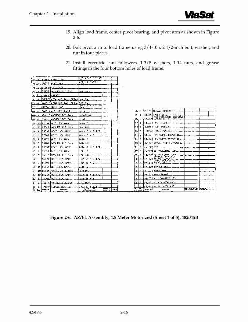
21. Install eccentric cam followers, 1-3/8 washers, 1-14 nuts, and grease fittings in the four bottom holes of load frame.
Figure 2-6. AZ/EL Assembly, 4.5 Meter Motorized (Sheet 1 of 5), 482045B
42S199F 2-16

Chapter 2 - Installation
Figure 2-6. AZ/EL Assembly, 4.5 Meter Motorized (Sheet 2 of 5), 482045B
42S199F 2-17

Chapter 2 - Installation
Figure 2-6. AZ/EL Assembly, 4.5 Meter Motorized (Sheet 3 of 5), 482045B
42S199F 2-18

Chapter 2 - Installation
Figure 2-6. AZ/EL Assembly, 4.5 Meter Motorized (Sheet 4 of 5), 482045B
42S199F 2-19

Chapter 2 - Installation
Figure 2-6. AZ/EL Assembly, 4.5 Meter Motorized (Sheet 5 of 5), 482045B
42S199F 2-20

Chapter 2 - Installation
2.11.1 Adjustment of Eccentric Cam Followers
The eccentric cam followers were installed during the assembly procedure to give maximum clearance between the rollers and the surface of the azimuth ring. It is now necessary to adjust the eccentric cam followers such that the clearances between them and the azimuth ring are kept to a minimum. The following procedure shall be used to accomplish this.
1. Insert an allen wrench in one end of eccentric cam follower and rotate cam until contact is made with the azimuth ring.
2. Apply a firm grip on the allen wrench and torque the 1-14 nut to 150 ft-lbs (203 Nm).
3. Repeat steps 1 and 2 for all eccentric cam followers.
2.11.2 Installation of Azimuth Actuator
Refer to Figure 2-6 and perform the following procedure to install the azimuth actuator:
1. Locate the azimuth actuator assembly, two azimuth pivot pins, 1/4-20 x 5/8 screws, and washers.
2. Position the azimuth actuator on the load frame and apply a small amount of grease to the pivot pins.
CAUTION
Be sure not to damage grease fittings when installing pivot pins.
3. Install pins through the load frame bores and into the azimuth lead screw housing.
4. Secure pivot pins using 1/4-inch hardware in six places.
5. Align azimuth clevis with torque arm and bolt in place using 5/8-11 x 2 1/4-inch bolts, washers, and nuts in four places.
6. Adjust clevis plates in slots so that the torque arm, clevis plates, and azimuth trunnion is in line at zero azimuth position.
NOTE
The azimuth actuator shall be run ±90° from zero. Adjust clevis plates as required if binding occurs.
42S199F 2-21

Chapter 2 - Installation
7. Once the clevis plates are properly set and all 5/8-inch hardware is torqued, drill 1/4-inch diameter through pilot holes in top clevis plate, torque arm, and bottom clevis plate.
8. Install 1/4-inch diameter x 1.50-inch long steel spring pin in two places.
2.11.3 Installation of Azimuth Stabilizer Assembly
1. Refer to Figure 2-6 and perform the following to install the azimuth stabilizer assembly:
2. Position azimuth stabilizer assembly to azimuth lead screw housing and bolt in place using 1/4-20 screw and washer in three places.
3. Position azimuth stabilizer guide bracket to torque arm and bolt in place using 3/8-16 x 2-inch bolt, washer, and nut in two places.
NOTE
Field adjustment is required on stabilizer guide bracket at zero azimuth angle.
4. Allow guide bracket to touch both cam followers, then push bracket into the cam followers an additional 1/8-inch.
5. Torque fasteners.
CAUTION
Use care not to damage grease fittings during installation of grease fittings. The grease fittings must be positioned toward the outside of the mount.
2.11.4 Installation of Elevation Actuator
The elevation actuator is attached to the mount with pivot pins. Each elevation actuator pivot pin is designed with grease fittings and shall be installed on the mount with the grease fittings positioned toward the outside.
42S199F 2-22

Chapter 2 - Installation
WARNING
A shear pin is provided in both the manual drive adapter and drive coupling between the reducer and jack. Only the specified shear pin shall be used during the operation of the antenna. Any modification or substitution to the specified shear pin without written approval by ViaSat Antenna Engineering will void all warranties and shall nullify ViaSat of all liability of property or personal injury.
Refer to Figure 2-6 and perform the following to install the elevation actuator:
CAUTION
The elevation actuator should only be manually driven when electrical power is not available.
1. The elevation actuator can be driven manually when electrical power is not available. Manually release the motor brake by rotating the brake release level 90°.
2. Attach a 1-inch socket to the manual drive adapter located on the elevation jack and rotate as required.
3. Position the elevation actuator to the load frame and install the lower clevis pin and spiral retaining rings in two places.
2.11.5 Installation of Hub Support Brackets
Refer to Figure 2-6 and perform the following procedure to install the hub support brackets.
NOTE
All hardware used to attach support brackets to the hub must remain loose until after the elevation pivot pins are installed.
1. Attach elevation jack clevis support bracket to bottom of hub with 1/2-13 x 2-inch bolts, washers, and nuts.
42S199F 2-23

Chapter 2 - Installation
NOTE
Bolts must be oriented with nuts on top side because of clearance considerations.
2. Attach three hub stabilizer braces to hub with 3/8-16 x 1 1/2-inch bolts, washers, and nuts.
3. Attach right hand and left hand elevation pivot brackets to hub with 1/2-13 x 2 1/2-inch bolts, washers, and nuts.
CAUTION
The elevation axis pivot pins are designed with grease fittings and are installed on the mount with grease fittings positioned toward the inside of elevation pivot ears. This allows for proper installation of elevation LSR drive bracket. Use care not to damage grease fittings during installation.
4. Position right hand and left hand elevation pivot brackets over load frame ears and install pivot pins and spiral retainer rings.
5. Torque all 3/8-16 hardware in step 2 to 30 ft-lbs (40 Nm).
6. Torque all 1/2-13 hardware in steps 1 and 3 to 75 ft-lbs (100 Nm).
42S199F 2-24

Chapter 2 - Installation
2.12 ASSEMBLY OF REFLECTOR
CAUTION
If it is necessary to walk inside the reflector during assembly, be sure to walk on the portion of the reflector closest to the Hub and directly over the Ribs. Any weight placed on unsupported parts of the reflector Panels can deform the Panel curvature, which will severely degrade Antenna performance.
The following procedure describes the complete assembly of the reflector, which includes the reflector Hub, Panels, Ribs, and Braces. The procedure is as follows:
1. Adjust the Elevation Actuator until the Hub assembly is near horizontal with respect to the A-frame, i.e., looking at zenith.
NOTE
Loosely install all hardware (unless otherwise instructed) until assembly of the reflector is completed. The recommended screw tightening procedure is provided at the appropriate stage of installation.
Install spring pins in the Hub top and bottom, and the straight end of the Panel Braces where they will be attached to the Ribs.
2. Attach the bent end of a Panel Brace (flat side down) onto the lower Hub flange using either a 1/2-13 x 1-1/2 bolt and nut, or a 1/2-13 x 2-1/2 bolt and nut (previously installed to attach the Hub Brace to the lower flange). Tighten the 1/2-13 bolt to no more than 2 ft-lbs. This is connection "A". Use washer on "nut side" of joint.
CAUTION
Do not apply any weight to the Panel Brace before it is attached to its Rib, as this could cause it to be bent near the Hub flange.
42S199F 2-25

Chapter 2 - Installation
3. Attach a Rib to the underside of the upper Hub flange and onto the spring pin. Fasten with a 3/8-16 x 1-1/4 bolt and nut. This is connection "B". Make sure that the Rib is supported by hand until STEP 4 is completed. Refer to Figure 2-7.
Figure 2-7. Assembly and Adjustment of Rib and Panel Brace
4. Attach the upper end of the Panel Brace to the Rib so that the spring pin is fully inserted through both parts. Fasten using a 3/8-16 x 1-1/4 bolt, washer, and nut. This is connection "C". Tighten the 3/8-16 bolts of connections "B" and "C" to 31 ft-lbs. Refer to Figure-2-7.
Repeat STEPs 2 through 4 above until all Panel Braces and Ribs have been installed. Note that the bolt and nut for six of the Panel Brace attachment points at the bottom of the Hub will already be in place, holding the Hub to the Pivot Brackets and Upper Actuator Bracket.)
5. To ensure that the Ribs are properly set for the most accurate reflector surface, a Rib Setting Template is supplied.
a. Place the template on the top of the Hub where the Panels will attach, using two tapered dowel pins as shown in Figure 2-8. Hold the template flat against the top of the Hub and examine the alignment of the hole at the small end of the template with the hole below it in the Rib. If the holes are not aligned, the bolt at connection "A" must be loosened just enough to allow movement.
42S199F 2-26

Chapter 2 - Installation
b. If the holes are not aligned laterally, the bolt at connection "B" must be loosened just enough to move the Rib and align the holes. After moving the Rib, retighten the bolt.
PINS
ALIGN RIB HOLE
TEMPLATE
SCREW "B"
NSG 1436A
Figure 2-8. Template Installation
c. With the Rib and template holes aligned laterally, inspect the longitudinal alignment. If they are not aligned, push the rib to the left or right to slightly bend it at the location shown in Figure 2-9. This will lengthen or shorten the rib, allowing alignment of the rib and template holes longitudinally, but it will cause a lateral misalignment of the holes.
Repeat STEPs 5b and 5c until the holes in the template and Rib are aligned exactly, and the tapered pins will insert partially into both parts.
42S199F 2-27

Chapter 2 - Installation
Figure 2-9. Tapered Pins
d. Retighten the bolt at connection "B" to 31 ft-lbs, and tighten the bolt at connection "A" to 76 ft-lbs, ensuring that the Rib does not become misaligned during the tightening.
Perform the inspection and adjustment procedure of STEP 5 on each of the Ribs.
6. Insert three 1/4-20 screws through the reflector Center Plate and spacers, and install the Plate into the center of the Hub. The surface of the Plate should be even with the Panels, once the Panels are installed.
7. Place two overlapping reflector Panels onto Ribs. Use a 1/4-20 x 1-3/4-inch panel mounting screw to attach the panels to the center of the Hub. Use a 1/4-20 x 5/8-inch panel mounting screw, washer, and nut (eight places) along the common Panel edges to join the Panels to the common Rib. Continue installing Panels in a counter-clockwise direction onto the reflector.
42S199F 2-28

Chapter 2 - Installation
NOTE
Every third Panel joint will require a 1/4-20 x 1-inch socket head screw in the hole near the outside diameter of the reflector to accommodate the spar support bracket during FEED INSTALLATION described later. The spar brackets should be positioned so that in the completed reflector the spars will appear to be at 45 degrees to the ground.
Tighten each panel screw just enough so that there is no gap between the two panels or the bottom panel and rib, but the two panels can still slip laterally with respect to each other.
8. If the reflector is to be used for transmit, a panel shape template is supplied to ensure that the panels maintain their accuracy during the shipping and installation process. Refer to Figure 2-10.
a. Place the template into the concave side of the Panel surface, with the ends of the template curve at the corners of the wide end of the Panel. The template should be positioned perpendicular to the panel surface.
b. If a gap of more than 1/32" (0.03") is observed at the mid-position of the panel-template interface, gently push upward on the panel rim to "straighten" the panel slightly. Repeat until the panel curvature matches the template as closely as possible.
c. If a gap of more than 1/32" (0.03") is observed at either end of the panel-template interface, gently pull down on the panel rim to "curve" the panel more. Repeat until the panel curvature matches the template as closely as possible.
Repeat the above procedure for all 12 Panels.
42S199F 2-29

Chapter 2 - Installation
Figure 2-10. Placing the Template onto the Panel
9. A "stringing" procedure will help to further ensure that the reflector will have the best surface accuracy, and thus achieve the best performance possible for Ku or transmit operation. Refer to Figures 2-11A and 2-11B. Proceed as follows:
a. Choose three Ribs equally spaced around the reflector (120 degrees apart). Attach a length of 8-10 lb. fishing line (.010-.012 inch diameter) across the reflector between two of the three chosen points. Seat the line in the left side of the corner notch between two Panels. Fasten the line to the rib below using strapping tape.
Figure 2-11A. Stringing the Reflector Figure 2-11B. Locating the Strings for Rib Adjustment
42S199F 2-30

Chapter 2 - Installation
b. Similarly stretch two more lengths of line between the other chosen points to form an equilateral triangle on the reflector. Tighten the fasteners at connection "C" for the three ribs located at the apexes of the triangle.
c. Stretch another line from one triangle apex (in the left corner of the notch) to one of the three opposite notches included within the triangle. Where this movable string crosses the opposite leg of the triangle, the lines should just touch each other. If the lines more than touch, i.e., one actually displaces the other, or, if a gap is observed between them, then the corresponding Rib must be raised or lowered. In order to raise or lower a Rib, the attached Panel Brace must be loosened slightly from it at connection "C". Two persons are required, one to hold the Rib in position, and one to retighten the bolt at the Panel Brace connection, since accuracy is critical.
d. Similarly measure and adjust the other two Ribs that fall within the same part of the triangle.
e. Reposition the movable line at each of the other two apexes of the triangle, similarly adjusting the opposite Ribs which fall within the corresponding sector of the triangle.
When the above procedure has been completed, the Panel joints at the rim of the reflector should lie in an almost perfect plane.
10. Torque all panel fasteners to 7-9 lb-ft if using a torque wrench, or 1/2 - 2/3 turn past snug tight if no torque wrench is available. To avoid distortion of the reflector during tightening, use the following sequence:
a. Starting at any reflector Panel, tighten each of the bolts at Location 1, the bolts which hold the Panels to the Hub.
b. Tighten the next larger Ring of bolts and continue tightening bolts in ever-increasing concentric circles, until the reflector is completely tight.
11. Re-check the panel curvature according to the procedure in STEP 8. Also, re-check the stringing accuracy of the reflector, according to STEP 9, to verify that the reflector shape was maintained during the panel screw tightening sequence.
If the reflector requires further adjustment, loosen the panel screws and repeat STEPs 8 through 10 until the reflector aperture is flat.
Remove the reflector alignment strings.
e. Once the four main ribs are set, make up another line long enough to go across the reflector and drape over the outside about 1 foot on either side. Tie a 1-inch nut to each end of the line to weight it down.
f. Stretch the movable line across the reflector at a position which doesn’t already have a line. It is not necessary to tape it because of the weights on each end. Adjust each of the ribs beneath this line until the line just touches the lines which form the sides of the “square”.
42S199F 2-31

Chapter 2 - Installation
g. Repeat step f. for the remaining three positions on the reflector, so that the panel joints at the rim of the reflector are made to lie in an almost perfect plane.
h. Remove the lines and the tape.
2.12.1 Installation of Feed
Each procedure below describes the installation of the manually polarized feed onto the Series 8345 Earth Station Antenna. Installation drawings for the motorized feeds are appended at the back of this manual. Procedures for both the C-band and the Ku-band feed are included; therefore, use appropriate procedure. Each procedure contains instructions for assembling the feed, installing the support spars onto the antenna, and attaching the feed to the support spars. The procedure is as follows:
2.12.2 Installation of C-Band Feed
Install a typical C-band feed using the following procedures.
NOTE
If Ku-band feed is used, skip this procedure and use the procedure specifically for the Ku-band feed. This procedure is only applicable to installation of the C-band feed.
1. Apply a thin coat of grease to the ridge surface and the groove surface of each half of the feed housing. Place the feed horn into the feed housing, and bolt the two halves of the feed housing together using 10-24 x 1 3/8-inch bolt, washer, and nut, two places, and 10-24 x 3/4-inch bolt, washer, and nut, two places. Snap feed window into place on feed horn. (See Figure 2-12.)
2. Manually rotate the feed horn within the feed housing and verify smooth operation with no binding.
3. Bolt each of four spar support brackets to the outside edge of reflector using 1/4-20 x l-inch hex socket-head screws previously installed. (See Figure 2-13.)
4. Attach each of four support spars to the spar support bracket using bolt, washer, and nut, six places. (See Figure 2-13.)
5. Attach assembled feed housing to support spars and loosely bolt in place using 1/4-20 x 1 1/4-inch bolt, washer, and nut, eight places. (See Figure 2-14.) Make sure that the feed rotates freely. Tighten fasteners to finger tight. Then tighten the nut on each screw an additional 2/3 turn but no more than 1 additional turn.
.
42S199F 2-32

Chapter 2 - Installation
Figure 2-12. Feed and Feed Housing Assembly (C-Band)
Figure 2-13. Attachment of Spars to Support Brackets
42S199F 2-33

Chapter 2 - Installation
Figure 2-14. Installation of Feed Housing and Orthomode Transducer
42S199F 2-34

Chapter 2 - Installation
6. Position orthomode transducer (OMT) against feed housing assembly, aligning holes in orthomode transducer with holes in feed horn. Be sure to orient the OMT to the feed as shown. Attach a friction device at top and bottom of orthomode transducer by aligning hole in each friction device with hole in orthomode transducer and feed horn. Bolt orthomode transducer and friction devices to feed horn using 10-24 x 3/4-inch screw and washer, two places. (See Figure 2-14.)
7. Install LNAs/LNBs (as applicable) to orthomode transducer using 1/4-20 x 1 1/4-inch bolt, washer, and nut, in four places per LNA/LNB. (See Figure 2-15.) Attach terminal lug to LNA/LNB to orthomode transducer. Insert braided shield into slot in terminal lug, and fasten in place using 1/4-20 x 1/2-inch screw
8. Attach coaxial cable to each LNA or LNB and secure with cable tie as shown in Figure 2-15. Make loop (approximately 5-inch radius) in both cables and braided shield. Route coaxial cables and braided shield down along the groove in the support spar and secure cables to support spar using cable ties equally spaced. Coaxial cables and braided shield should be draped over outside edge of reflector and routed down along the panel shield to terminal lug using 1/4-20 x 1/2-9 inch screw.
NOTE
Be sure to allow enough slack in the coaxial cables between the LNAs/LNBs and the support spar so that the feed can be rotated.
9. Install one half of LNA/LNB cover to orthomode transducer using 10-24 x 3/4-inch bolt, washer, and nut. (See Figure 2-16.) Install other half of LNA/LNB cover to orthomode transducer using 10-24 x 3/4-inch bolt, washer, and nut. Bolt both halves of LNA/LNB cover together using 8-32 x 7/16-inch pan-head bolt, washer, and nut, seven places.
42S199F 2-35

Chapter 2 - Installation
Figure 2-15. Installation of LNAs/LNBs
42S199F 2-36

Chapter 2 - Installation
Figure 2-16. Installation of LNA/LNB Cover
42S199F 2-37

Chapter 2 - Installation
2.12.3 Installation of Ku-Band Feed
Install a typical Ku-band feed using the following procedures.
NOTE
If the C-band feed is used, do not use this procedure. Instead, use the procedure specifically for the C-band feed. This procedure is only applicable to installation of the Ku-band feed.
1. The feed window is a small sheet of llumar (a clear plastic-like material), 3.45 inches diameter and 0.005 inches thick. It can be found in the feed pack in a small plastic sheath marked 301676. The window installs into a small groove in the front of the corrugated flange of the feed. Refer to Figure 2-17 and perform the following:
a. Stand the feed on a flat surface such as a table, with the corrugations facing up.
b. Lay the window on top of the corrugations, and flex it in the middle slightly, so that part of the edge may be inserted into the groove.
c. While holding the window near the point it was first inserted, slowly work the remainder of the window into the groove. Work away from the starting point in both directions using both hands, all the way around the periphery of the window to the opposite side. When almost all the window is in the groove, it will be buckled near the part which isn't in the groove.
d. While holding the window against the face of the corrugations, the remainder of the window may be guided into the groove using a fingernail.
2. If the preceding procedure should prove too difficult, an alternative method of installation may be used. Refer to Figure 2-17 and perform the following:
a. Using a pair of scissors or a razor blade, make a 1/8 inch long cut in the window from the edge toward the center.
b. Bend the window on one side of the cut down into the groove in the feed, and screw the window into the groove. As the window is turned, guide the edge into the groove using a finger or fingernail.
c. The window is properly installed when it can be easily spun in the groove using a finger.
42S199F 2-38

Chapter 2 - Installation
Figure 2-17. Feed Window Installation
3. Apply a thin coat of grease to the ridge surface and the groove surface of each half of the feed housing.
4. Slip clamp ring into place on feed horn and align holes in clamp ring with three outside holes of feed horn.
5. Insert each of the three 10-32 x 3/4-inch screws through the outside holes of the feed and thread through the clamp ring.
6. Attach a terminal lug to the outside edge of the feed using 1/4-20 x 3/4-inch screw and washer.
7. Insert braid shield into slot in terminal lug, and fasten in place using 1/4-20 x 1/2-inch screw.
8. Place the feed horn into the feed housing making sure that the ridge of the feed housing is between the feed and the clamp ring, and bolt the two halves of the feed housing together using 10-24 x 1 1/2-inch bolt, washer, and nut, two places, and 10-21 x 3/4-inch bolt, washer, and nut, two places. (See Figure 2-18.)
9. Manually rotate the feed horn within the feed housing and ensure operation with no binding.
42S199F 2-39

Chapter 2 - Installation
Figure 2-18. Feed and Feed Housing Assembly (Ku-Band) Figure 2-18. Feed and Feed Housing Assembly (Ku-Band)
10. Bolt each of four spar support brackets to the outside edge of reflector using 1/4-20 x l-inch hex socket-head screws previously installed. (See Figure 2-19.)
10. Bolt each of four spar support brackets to the outside edge of reflector using 1/4-20 x l-inch hex socket-head screws previously installed. (See Figure 2-19.)
11. Attach each of four support spars to spar support bracket using 1/4-20 x 1 1/4-inch bolt, washer, and nut, six places. (See Figure 2-19.)
11. Attach each of four support spars to spar support bracket using 1/4-20 x 1 1/4-inch bolt, washer, and nut, six places. (See Figure 2-19.)
Chapter 2 - Installation
42S199F 2-40
Figure 2-19. Attachment of Spars to Support Brackets
42S199F 2-40

Chapter 2 - Installation
12. Attach assembled feed housing to support spars and loosely bolt in place using 1/4-20 x 1 1/4-inch bolt, washer, and nut, in eight places. See Figure 2-20. Make sure that the feed rotates freely. Tighten all fasteners to finger tight. Then tighten the nut on the screw an additional 2/3 turn, but no more than 1 additional turn.
13. Position orthomode transducer (OMT) against feed housing assembly, aligning holes in orthomode transducer with four inside holes of feed horn. Bolt orthomode transducer to feed horn using 6-32 x 5/8-pan head screw, in four places. (See Figure 2-20.)
14. Install LNAs/LNBs (as applicable) to orthomode transducer using M4-x .7 pitch x 14 mm (metric) bolt, washer, and nut. (See Figure 2-20.)
15. Attach coaxial cable to each LNA or LNB and secure with cable tie as shown in Figure 2-20.
16. Make loop (approximately 5-inch radius) in both cables and braided shield. Route coaxial cables and braided shield down along groove in support spar and secure cables to support spar using cable ties equally spaced. Coaxial cables and braided shield should be draped over outside edge of reflector and routed down along the panel brace.
Figure 2-20. Installation of Feed Housing, OMT and LNAs/LNBs
42S199F 2-41

Chapter 2 - Installation
17. Insert end of braided shield into slot in terminal lug already installed on ground attachment lug which is attached to support arm. Secure braided shield to terminal lug using 1/4-20 x 1/2-inch screw.
NOTE
Be sure to allow enough slack in the coaxial cables between the LNAs/LNBs and the support spar so that the feed can be rotated.
18. Install LNA/LNB cover on the feed housing using 10-24 x 3/4-inch bolt, washer and nut in four places, refer to Figure 2-21.
Figure 2-21. Installation of LNA/LNB Cover
42S199F 2-42

Chapter 2 - Installation
2.13 Technical Drawings
The following list contains technical drawings required for installation of the 4.5M antenna. The list is given in the order the drawings appear on the following pages.
Part No. Rev. Title 367733 B Motorized 4.5-Meter Ku-Band Feed Installation
367730 D Motorized 4.5-Meter Ku-Band Feed Assembly
42S199F 2-43

Chapter 2 - Installation
215 13 71505 Nut, Hex 10 – 24 SST 214 19 174557 Washer, Lock No. 10 SST 213 32 73275 Washer, Flat No. 10 SST 212 19 72460 Screw, Pan No. 10 – 24 x ¾ SST 211 5 176575 Clamp 1 ¼ in 210 5 84737 Clamp ½ in 209 5 170724 Screw, Hex HD ¼ - 20 x ½ zinc 208 10 83420 Cable Tie 207 3 173841 Gasket 206 12 72378 Screw, pan HD 6- 32 x ¾ SST 205 16 73270 Washer, Flat No. 6 SST 204 12 174555 Washer, lock No. 6 SST 203 4 75446 Nut, Hex 6 –32 SST 202 27 88711 Nut, Hex ¼ - 20 zinc 201 54 88536 Washer, Flat ¼ Zinc 200 22 88524 Screw, Hex HD ¼ - 20 x 1 ¼
14 1 364651 Waveguide 13 1 364548 Waveguide 12 4 364522 Spacer 11 4 364527 Bracket, SPAR 10 4 301892 SPAR, Feed
5 5 369764 Spacer 4 2 301817 Lug, Ground ATCH 3 2 87544 Terminal Lug 2 1 300936 HDW, Grounding Kit 1 1 367730 Feed Assy
Parts List
Figure 2-22. Motorized 4.5-Meter Ku-Band Feed Installation (Sheet 1 of 3), 367733
42S199F 2-44

Chapter 2 - Installation
Figure 2-22. Motorized 4.5-Meter Ku-Band Feed Installation (Sheet 2 of 3), 367733
42S199F 2-45

Chapter 2 - Installation
Figure 2-22. Motorized 4.5-Meter Ku-Band Feed Installation (Sheet 3 of 3), 367733
42S199F 2-46

Chapter 2 - Installation
Figure 2-23. Motorized 4.5-Meter Ku-Band Feed Assembly (Sheet 1 of 10), 367730
42S199F 2-47

Chapter 2 - Installation
Figure 2-23. Motorized 4.5-Meter Ku-Band Feed Assembly (Sheet 2 of 10), 367730
42S199F 2-48

Chapter 2 - Installation
Chapter 2 - Installation
42S199F 2-49
Figure 2-23. Motorized 4.5-Meter Ku-Band Feed Assembly (Sheet 3 of 10), 367730
42S199F 2-49

Chapter 2 - Installation
Chapter 2 - Installation
42S199F 2-50
Figure 2-23. Motorized 4.5-Meter Ku-Band Feed Assembly (Sheet 4 of 10), 367730
42S199F 2-50
Chapter 2 - Installation
Chapter 2 - Installation
42S199F 2-51
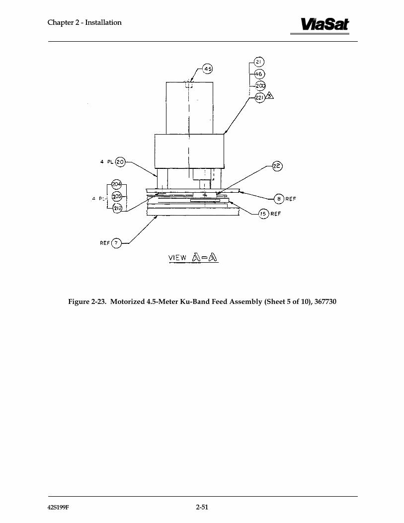
Figure 2-23. Motorized 4.5-Meter Ku-Band Feed Assembly (Sheet 5 of 10), 367730
42S199F 2-51

Chapter 2 - Installation
Figure 2-23. Motorized 4.5-Meter Ku-Band Feed Assembly (Sheet 6 of 10), 367730
42S199F 2-52

Chapter 2 - Installation
Figure 2-23. Motorized 4.5-Meter Ku-Band Feed Assembly (Sheet 7 of 10), 367730
42S199F 2-53
Chapter 2 - Installation
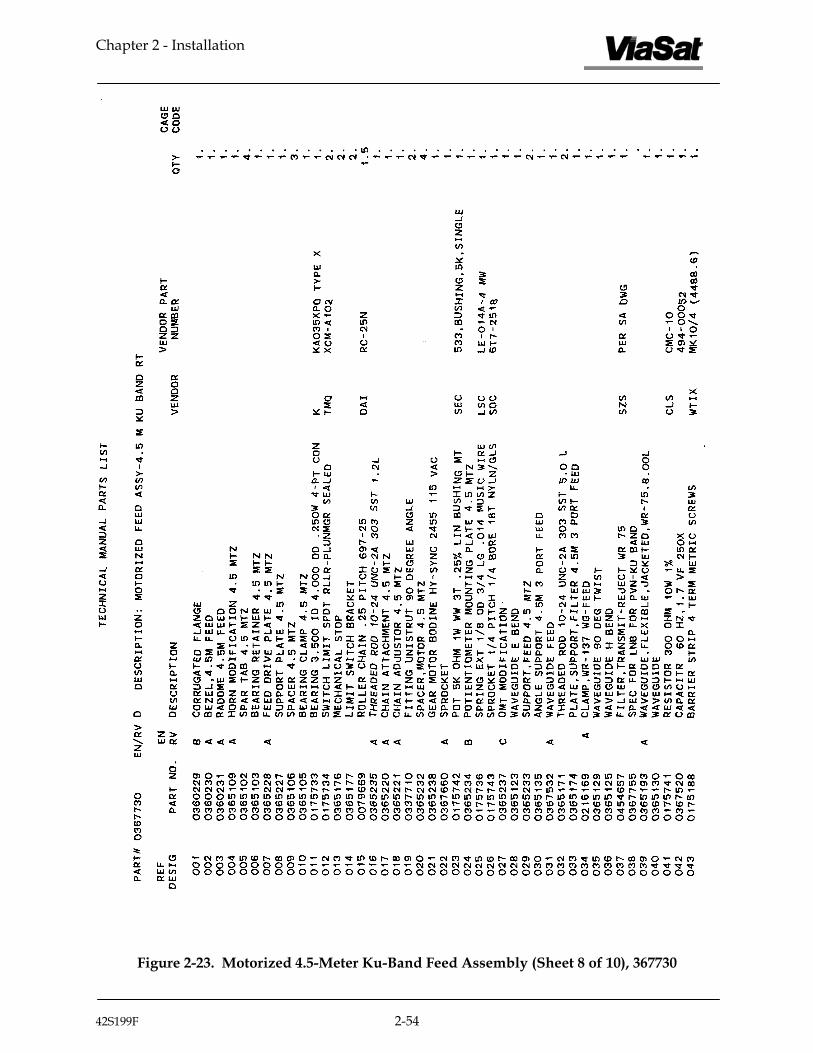
Figure 2-23. Motorized 4.5-Meter Ku-Band Feed Assembly (Sheet 8 of 10), 367730
42S199F 2-54

Chapter 2 - Installation
Figure 2-23. Motorized 4.5-Meter Ku-Band Feed Assembly (Sheet 9 of 10), 367730
42S199F 2-55

Chapter 2 - Installation Chapter 2 - Installation
42S199F 2-56
Figure 2-23. Motorized 4.5-Meter Ku-Band Feed Assembly (Sheet 10 of 10), 367730
42S199F 2-56

Chapter 3 - Operation
Chapter 3
Operation
3.1 General
This chapter contains procedures for satellite pointing, focal length inspection and adjustment, and equipment required for transmit patterns.
3.2 Satellite Pointing Procedure
With the feed installed and the electronics operational, use the following procedure for pointing at the desired satellite and peaking on the signal.
1. Refer to the Site Preparation manual to determine the required elevation and azimuth angles.
2. Using an inclinometer or angle indicator held across the actuator bracket of the hub, move antenna to the required elevation angle by turning the elevation actuator on, until the required angle is obtained.
3. Rotate the antenna in azimuth until the satellite signal has been picked up.
4. Peak up the signal by jogging the elevation and azimuth actuators as necessary until the signal strength is at maximum.
3.3 Focal Length Inspection And Adjustment
The following should be performed for the focal length inspection and adjustment.
1. Measure C/N for antenna as it is.
2. Measure the feed location with respect to the reflector. This is measurement M. Refer to Figure 3-1.
3. If M is less than 62.0 inches, follow the adjustment procedure.
42S199F 3-1

Chapter 3 - Operation
3.3.1 Adjustment Procedure
The following is the focal length adjustment procedure.
1. Subtract the feed measurement M from 62.12, giving difference D.
D=62.12 - M
2. Attach the feed spars to the dish with the slotted brackets. Use only one screw, in the hole near the end of the spar.
3. Set each spar screw so that it is located a distance D above the mark on the spar bracket and tighten. Refer to Figure 3-1.
Figure 3-1. Focal Length Inspection and Adjustment
4. Re-measure the feed location, and verify that its new distance L from the reflector is given by the equation:
L=62.12 + (1.5 x D)
If not, incrementally adjust all spars by equal amounts to obtain measurement L.
5. Re-measure C/N.
42S199F 3-2

Chapter 3 - Operation
3.4 Equipment Required For Transmit Patterns
The following represents a list of equipment required to run transmit patterns. This assumes that the system under test has transmit capability.
• 70 MHz IF Source (stable)
• C-Band/Ku-Band upconverter (whichever is applicable) (stable)
• Cooperating earth station with spectrum analyzer and chart recorder (HP 8566B preferred) and voice link with earth station under test.
• Satellite transponder time must be acquired on a satellite that is viewable from both the station under test and the cooperating earth station.
42S199F 3-3

Chapter 3 - Operation
Blank
42S199F 3-4

Chapter 4 - Maintenance
Chapter 4
Maintenance
4.1 General
The Series 8345 4.5-Meter Prime Focus Motorized Antenna is designed for use in many different environmental conditions with minimum maintenance requirements. Several areas on the antenna require service at various intervals to ensure the proper use and operation. Modification to the suggested service intervals is expected pending customer operation and environmental conditions. The elevation pivot points are designed with grease fittings and require lubrication. The azimuth axis rotates on rollers about the azimuth ring, which requires a light film of grease on the roller surface. Grease fittings are supplied for roller lubrication. The azimuth and elevation actuators contain a gearbox or reducer and a machine screw mechanism which require inspection and application of lubricant as required. Grease fittings are supplied to lubricate azimuth lead screw support bearings. Boots are supplied on each actuator which require inspection. The prime focus polarization drive mechanism requires no lubrication, but must be inspected to ensure proper operation. Structural fasteners used on the mount, actuators, reflector, and prime focus feed may require additional corrosion protection.
4.2 Periodic Maintenance
The suggested service intervals apply to a typical antenna installation and may vary due to environmental conditions.
4.2.1 Weekly Maintenance
Perform the following procedures at least once every week.
1. Ensure dehydrator compressor desiccant is functional (per color chart). Check pressure and maintain approximately 0.25 psi, open drain valve in pressure tank to remove water accumulation.
2. Ensure motorized antennas are driven in azimuth and elevation on a weekly basis. In areas of heavy snow and ice, mounts should be inspected before movement for excessive accumulation of ice, or damage may result.
42S199F 4-1
Chapter 4 - Maintenance
4.2.2 Monthly Maintenance
NOTE
If it has been some time since electrical power was applied to the actuator motors, go to the antenna and remove all electrical power, manually release the motor brake and rotate motor shaft. Once it is determined that the brake will release and the shaft will turn freely, then apply electrical power to the motors.
Apply electrical power, as necessary, to azimuth actuator, elevation actuator, and polarization drive assembly. Run each axis for two or three minutes in the normal operating sector. Inspect drain holes in actuator motors; holes should be open for condensation drainage. Observe brake operation if applicable.
4.2.3 Bi-Monthly Maintenance
Perform the following procedures at least once every two months.
WARNING
Remove electrical power from antenna system prior to performing bi-monthly maintenance.
1. Remove LSR covers, inspect mechanical operation, and check for condensation accumulation. If moisture exists, open all drain holes. Apply a spray-type lubricant (WD-40 or equivalent) to all moving parts. Secure covers.
2. Remove hub cover. Inspect polarization drive assembly, apply a spray-type lubricant (WD-40 or equivalent) to chain and drive sprocket. Inspect the feed chain for correct tension and lubricate if necessary with the spray-type lubricant. Ensure that feed rollers are all functional, inspect flexible transmit waveguide jumpers, if applicable, for fatigue, check limit switch operation. Inspect feed window for damage, replace window as required. Secure cover.
3. Inspect all cotter pins and other devices used as pin retainers. Replace if damages or corroded; tighten if loose.
4. Inspect mount, reflector, and feed, for loose or missing fasteners and replace as required.
42S199F 4-2

Chapter 4 - Maintenance
5. Check the oil level in both the azimuth and elevation actuator gear boxes and add Mobil SHC 634 oil, as required, to maintain a level of approximately half full.
6. Inspect azimuth machine screw. If the screws are coated with grease and the grease is in good condition, no further action is required. If either screw is not adequately coated, or if the grease is dry, hard, or contaminated, the lubricant must be renewed. Do not add grease to old grease of the screw. Clean the screw of old grease using a solvent. Dry the screw with clean cloths. Apply a thin uniform film coating of one of the following low-temperature greases.
CAUTION
If one of the following low-temperature greases is not used on the actuator machine screw, damage to the screw or motor could occur.
• Texaco Low Temperature #2346
• Shell Aeroshell #7
• Mobil Low Temperature #28
7. Inspect azimuth and elevation boots. Replace as required.
8. The antenna rotates in azimuth on rollers rotating about the azimuth ring. Inspect rollers and apply a thin uniform coationg of grease to the contact surfaces of all rollers.
CAUTION
Do not over lubricate elevation actuator housing. Over lubrication will result in damage to shaft seals.
9. Remove the grease fitting from the side of the elevation actuator housing. Inspect internal grease and add as required. Do not over lubricate. Over lubrication will damage shaft seals.
10. Locate two grease fittings, one at each end of azimuth actuator housing. Apply one or two shots of grease to lubricate the lead support screw bearings.
42S199F 4-3

Chapter 4 - Maintenance
4.2.4 Yearly Maintenance
Perform the following procedures at least once every year.
1. Inspect the foundation pad for structural cracks and repair as required.
2. Check torque values on all fasteners as follows:
Torque Values For Antenna Fasteners (High Strength Grade 5 Zinc or Galvanized Steel)
Fastener SizeTorque (ft-lb) tolerance ±10%
1/4-20 6 (8 Nm)
5/16-18 15 (20 Nm)
3/8-16 30 (40 Nm)
1/2-13 75 (100 Nm)
3/4-10 250 (except as noted) (333 Nm)
1-8 600 (except as noted) (813 N
_____________________________________________________________________
Torque Values For Antenna Fasteners (Stainless Steel)
Fastener Size Torque (ft-lb) tolerance ±10%
1/4-20 6 (8 Nm)
5/16-18 12 (16 Nm)
3/8-16 20 (26 Nm)
1/2-13 45 (60 Nm)
3/4-10 130 (except as noted) (173 Nm)
NOTE
The required torque value for the foundation anchor bolts is 100 lb-ft (136 Nm).
42S199F 4-4

Chapter 4 - Maintenance
4.3 Corrosion Protection
Perform the following procedures after completing the installation and every 12 months thereafter.
NOTE
Pressurization of transmit waveguide runs and feed components should be maintained to prevent moisture from entering the system. Receive only pressurization is optional.
1. Evaluate the corrosion protection on the mount, actuators, and related hardware. If the protective finish is damaged, clean with a wire brush, remove all rust, and apply a coat of Rust-Oleum (or equivalent) spray-on cold galvanizing compound.
2. Evaluate the corrosion protection on the reflector surface, spars, feed, potentiometer brackets and related hardware. If the paint is scratched, chipped, beginning to flake, or just wearing thin, lightly sand with 320 grit (or finer) sandpaper and apply a coat of Rust-Oleum (or equivalent) primer and semi-gloss white paint.
42S199F 4-5

Chapter 4 - Maintenance
Blank
42S199F 4-6