Embed Size (px)
Citation preview

Series 8345Prime-Focus Manual Antenna
Installation Manual
Manual 33N074MJuly 2008

Notice
All Rights Reserved
The information contained in this document is proprietary to Superior SatelliteEngineers, Inc. This document may not be reproduced or distributed in any formwithout the consent of Superior Satellite Engineers, Inc.
The information in this document is subject to change without notice. SSE, Inc.assumes no responsibility for any errors that may appear in this document anddoes not warranty any specific application.
Any product names mentioned herein are used for identification purposes only,and may be trademarks and/or registered trademarks of their respective companies.
In all correspondence with SSE, Inc. regarding this publication, please refer to theManual Part No. on the title page.
Copyright ® 2007 Superior Satellite Engineers, Inc.
All rights reserved. No part of this book may be reproduced in any form or byany means without permission in writing from SSE, Inc.

Table of Contents
33N074 Rev M iii
Table of Contents
Table of Contents ........................................................................................ iii
List of Figures ............................................................................................. v
List of Tables.............................................................................................. vi
Safety Summary......................................................................................... vii
General Information and Safety .................................................................. 1-1
1.1 Introduction......................................................................................................1-1
1.2 Safety Precautions ............................................................................................1-1
1.3 Equipment Description .....................................................................................1-3
1.4 Equipment Application.....................................................................................1-4
1.5 Standard Features ..............................................................................................1-4
1.6 Options.............................................................................................................1-5
1.7 Specifications....................................................................................................1-5
Antenna Site Selection ............................................................................... 2-1
2.1 Criteria For Antenna Site Selection...................................................................2-1
2.2 Determining Aiming Coordinates......................................................................2-1
2.3 Verifying Operational Clearance .......................................................................2-2
2.4 Verifying Clear Line-of-sight ............................................................................2-4
2.5 Verifying Absence of Signal Interference...........................................................2-4
Antenna Installation................................................................................... 3-1
3.1 Unpacking and Inspection.................................................................................3-1
3.1.1 Equipment Damage or Loss During Shipment....................................................3-1
3.1.2 Equipment Return Procedure.............................................................................3-1
3.2 Recommended Tools And Equipment................................................................3-2
3.3 Recommended Installation Sequence .................................................................3-3
3.4 Installation of Foundation and Feet...................................................................3-4
3.4.1 Wind-loading Information ................................................................................3-5
3.5 Installation of Typical Foundations ..................................................................3-9
3.5.1 Installing a Pier Foundation (In-ground Mount) ................................................3-9
3.5.2 Installing a Pad Foundation (Surface Mount)...................................................3-10

Table of Contents
33N074 Rev M iv
3.6 Assembly of Mount.........................................................................................3-11
3.7 Assembly Of Reflector....................................................................................3-29
3.8 Satellite Pointing Procedure............................................................................3-37

Table of Contents
33N074 Rev M v
LIST OF FIGURES
Figure 1-1. Series 8345 Earth Station Antenna..............................................................................1-3
Figure 2-1. Clearance Requirements for 4.5-Meter Antenna ..........................................................2-3
Figure 3.1. outline Dimensions of 4.5-meter Antenna ...................................................................3-4
Figure 3.2. Foundation Loading: Sign Conventions .......................................................................3-5
Figure 3.3. Pier Foundation, In-ground Mount.............................................................................3-12
Figure 3.4. Pad Foundation, Surface Mount..................................................................................3-13
Figure 3.6. Installation of Leg Assemblies....................................................................................3-15
Figure 3.7. Installation of Leg Support Bracket ...........................................................................3-16
Figure 3.8. Installation of Support Arms.......................................................................................3-17
Figure 3.9. Installation of Azimuth Ring......................................................................................3-18
Figure 3.10. Tightening Sequence for Pedestal .............................................................................3-20
Figure 3.11. Positioning A-frame on Azimuth Ring......................................................................3-21
Figure 3.12. Actuator Fitting Assembly .......................................................................................3-22
Figure 3.13. Installation of A-frame.............................................................................................3-23
Figure 3.14. Installation of Elevation Pivot Brackets..................................................................3-24
Figure 3.15. Attachment of Hub to A-Frame...............................................................................3-25
Figure 3.16. Installation of Hub Braces........................................................................................3-26
Figure 3.17. Actuator Installation................................................................................................3-28
Figure 3.18. Assembly and Adjustment ........................................................................................3-31
Figure 3.19. Template Installation ..............................................................................................3-31
Figure 3.20. Tapered Pins............................................................................................................3-32
Figure 3.21. Placing the Template onto the Panel.......................................................................3-34
Figure 3.22a. Stringing the Reflector Figure 3-22b. Locating the Strings................................3-35

Table of Contents
33N074 Rev M vi
LIST OF TABLES
Table 1-1. Series 8345 Antenna Specifications..............................................................................1-5
Table 3.1. Tools and Equipment Required for Installation .............................................................3-2
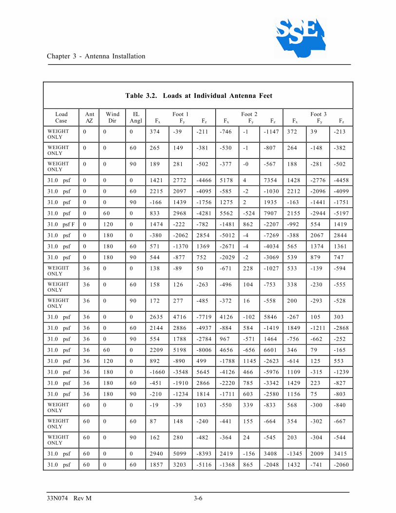
Table 3.2. Loads at Individual Antenna Feet..................................................................................3-6
Table 3.3. Total Loads on Foundation............................................................................................3-8

Safety Summary
33N074 Rev M vii
SAFETY SUMMARY
These are general safety precautions that are not related toany specific procedure. These are recommended precautionsthat personnel must understand and apply.
WARNING
Use care when using metal tools that circuits are not shorted.Some circuits have high current capacity which, whenshorted, will flash and may cause burns and/or eye injury.
Remove all jewelry and exposed objects from body andclothing before performing maintenance, adjustments, and/ortroubleshooting. Before working inside equipment, remove allpower, unless power is required to be on to performprocedures. Do NOT replace parts or modules with power ON.
Servicing this equipment requires working with the equipmentwhile AC power is applied. Extreme caution must be exercisedduring these procedures.
RESUSCITATIONPersonnel working with or near hazardous chemicals or voltages should befamiliar with modern methods of resuscitation.
USE SAFETY-APPROVED EQUIPMENTWhen cleaners are being applied, approved explosion-proof lights, blowers, andother equipment shall be used. Ensure that firefighting equipment is readilyavailable and in working order. Keep cleaners in special polyethylene bottles orin safety cans and in minimum quantities. Discard soiled cloths into safety cans.

Safety Summary
33N074 Rev M viii
This page is intentionally Blank

Chapter 1 - General Information and Safety
33N074 Rev M 1-1
Chapter 1
General Information and Safety
1.1 Introduction
This manual describes the proper installation of the Series 8345 earth stationantenna. The manual is divided into three chapters. Chapter 1 providesthe safety precautions involved with the installation of the antenna, anoverview of the antenna, its applications, features, specifications, physicaland functional descriptions of its components, and available options.Chapter 2 provides information for selecting and evaluating an antenna site.Chapter 3 provides unpacking and installation information, including toolsand equipment required, recommended installation sequence, and step-by-step installation procedures.
Important information concerning personal injury, damage to equipment,and increased efficiency or convenience is included as WARNINGS,CAUTIONS, and NOTES, respectively. Therefore, particular attentionshould be given to this information.
1.2 Safety Precautions
To ensure that installation is trouble-free, to minimize risks to installationpersonnel, and to prevent damage to equipment, it is necessary to observethe safety precautions provided below. Such information may be foundthroughout the manual in the form of a WARNING, CAUTION, or NOTEwhere:
WARNING
designates information concerning the possibility of bodilyinjury,
CAUTION
designates information concerning the possibility of damage tothe equipment or other property, and

Chapter 1 - General Information and Safety
33N074 Rev M 1-2
NOTE
designates information which may aid the efficiency andconvenience of installation.
Carefully read and understand the following safety precautions beforeattempting to install the equipment:
• Read all instructions carefully before installing the antenna.
• Adhere to all warnings and cautions contained in the installationinstructions.
• Make sure that at least two people are present at all times duringinstallation.
WARNING
Do not attempt to assemble the antenna in winds exceeding 20miles per hour.
The antenna system should not be located near, and itsmovement should not make contact with, power or otherelectrical circuits.
During installation, extreme care should be taken to keep fromtouching any power lines or other electrical circuits.
Failure to observe these warnings may result in severe injuryor death.

Chapter 1 - General Information and Safety
33N074 Rev M 1-3
1.3 Equipment Description
The Series 8345 earth station antenna (Figure 1-1) is designed for quick andeasy installation without special tools or hoisting equipment.
Figure 1-1. Series 8345 Earth Station Antenna
A concrete pier foundation kit is available as an economical alternative to aconcrete slab foundation. The pier foundation is designed for steady 110mph windloads. It consists of three cast pier inserts. A steel frameworkbolts the inserts into a triangle, which is lowered into three augered holescontaining prepared re-bar cages; the holes are then filled with concrete.Installing the pier foundation is less time-consuming and less expensivethan pouring a concrete slab foundation.
A standard elevation-over-azimuth mount is provided with the 4.5-meterantenna for both ease of operation and pointing accuracy. This mountprovides continuous satellite arc coverage from any location in thecontiguous United States. Pointing of the antenna is rapid and accurate. A5° to 90° elevation range is provided for maximum pointing capability.Complete 360° azimuth coverage eliminates the need to align the
WINDDIRECTION
FOOT 2
FOOT 1
13606
FOOT 3
+Z(OUT OF PAGE)
+X
AZ ANGLE
WIND ANGLE
+Y

Chapter 1 - General Information and Safety
33N074 Rev M 1-4
foundation to a specific heading, thereby also eliminating the possibility ofinstallation errors associated with foundation centerlines.
The paraboloidal reflector consists of twelve precision, stretch-stamped steelpanels for consistent surface accuracy. The twelve panels are uniform andcompletely interchangeable for handling convenience, lower shipping costs,and easy installation. After a foundation has been prepared, two people caninstall the antenna in one day. No special tools are required and no singlepart weighs more than 140 pounds (45 kg).
Each of the optional feeds offered with the 4.5-meter earth station antennaprovides consistent high quality and unusual economy in a mid-sizedantenna system. The Ku-band Feed provides dual-polarization, receive-only capability in the 10.9 to 12.75 GHz range. The C-band Feed providesdual-polarization, receive-only capability in the 3.7 to 4.2 GHz range.
1.4 Equipment Application
The 4.5-meter earth station antenna is designed for a wide range ofapplications and is especially well-suited for CATV operations receivingvideo programming from domestic satellites. Feeds are available for 3.7 to4.2 GHz receive-only applications, 10.9 to 12.75 GHz receive-onlyapplications.
1.5 Standard Features
The Series 8345 earth station antenna provides cost-effective highperformance for a wide range of applications and includes the followingfeatures:
• Ease of installation
• Minimum maintenance
• Minimum shipping and installation costs
• Minimum site preparation requirements
• Full satellite arc coverage from any location in the contiguous UnitedStates (5° to 90° continuous elevation; 360° continuous azimuth)
• Elevation-Over-Azimuth Mount for ease of operation
• Interchangeable, stamped reflector panels for consistent surfaceaccuracy (no panel adjustment or testing required)
• Protected environment for LNAs/LNBs
• Ku-band compatible

Chapter 1 - General Information and Safety
33N074 Rev M 1-5
1.6 Options
For added ease of installation and a wider range of applications, thefollowing options are available:
• Pier Foundation Kit (a low-cost alternative to the concrete slabfoundation)
• C/Ku-band Feed (for receive-only applications in the 10.9 to 12.75GHz range)
• Multi-beam Feed (for receiving up to 5 satellite beams -- fromsatellites spaced 2° to 8° apart --with one dish)
1.7 Specifications
The Series 8345 earth station antenna has been designed and tested to meetthe specifications listed in Table 1-1.
Table 1-1. Series 8345 Antenna Specifications1
Characteristic Specification
ELECTRICAL
Operating frequency C-band 3.7 to 4.2 GHzKu-band 10.9 to 12.75 GHz
Feed types Ku-band, dual polarizationC-band, dual polarizationC-band dual-beam
Antenna gain 43.6 dBi at 4 GHz53.1 dBi at 12 GHz
VSWR (Referenced at output of OMT) 1.3:1 maximum
Polarization Dual linear
Polarization adjustment 360° continuous
Axial ratio 35 dB minimum on axis
Isolation between ports 35 dB minimum for dual linear operation
Half-power beam width (-3dB reference) C-band 1.1° nominal @ 4 GHzKu-band 0.4° nominal @ 12 GHz
First sidelobe C-band -22.5 dB @ 4 GHzKu-band -20 dB @ 12 GHz
Antenna noise temperature C-band 24K at 30° elevationKu-band 28K at 30° elevation

Chapter 1 - General Information and Safety
33N074 Rev M 1-6
Table 1-1. Series 8345 Antenna Specifications1
Characteristic Specification
Radiation pattern C-band main beam <= theta <7.0 <29.0 - 25.0 (log (theta))dbiKu-band 1.0 <= theta < 7.0: <29.0 – 25.0 (log (theta)) dbiC- & Ku-band 7.0 <= theta < 9.2: < +8.0 dBi9.2 <= theta < 48.0: <32.0 – 25.0 (log (theta)) dBi48.0 <= theta < 180.0: < -10.0 dBi
Feed interface CPR-229 flange (C-band)WR-75 flange (Ku-band)
GENERAL
Antenna type Prime-focus, paraboloidal
Antenna diameter 4.5-meter (14.83 ft)
Reflector construction Stretch-stamped, 12-panel, 4.5-meter diameter
Mount configuration Elevation-over-azimuth
Azimuth coverage 360° continuous
Elevation range 5° to 90° continuous
Satellite coverage Any satellite in the visible geosynchronous arc, fromany location in the contiguous U.S.
ENVIRONMENTAL
Pointing accuracy .054° rms in 30 mph winds gusting to 45 mph @ 59° F
Temperature range (operational) -40°C to 65°C (-40° F to +149° F)
Survival2 Antenna designed to withstand steady winds up to 110 mph@ 59° F, 107 mph @ 32°F no ice, 99 mph @ -40° F no ice, 67mph @ 32° F with 2-inch radial ice. (Ref. American NationalStandard Building Code Requirements, ANSI A58.1, with aneffective velocity pressure of 30.9 psf.) Winds gusting to125�mph may cause some localized yielding.
Solar radiation 1. 1 mW/mm 2
Atmospheric conditions Salt, pollutants and corrosive contaminants as encountered intropical temperature, marine, and moderate industrial areas.
1Specifications subject to change without notice.2All conditions assume proper installation and adjustable components securely clamped.

Chapter 2 - Antenna Site Selection
33N074 Rev M 2-1
Chapter 2
Antenna Site Selection
2.1 Criteria For Antenna Site Selection
One of the most important factors to be considered for trouble-free, high-quality signal reception from desired satellites is the location of the antenna(the antenna site). For best signal reception, the antenna site selectedshould provide the following:
a. Operational Clearance. The site must allow clearance for antennamovement (in both elevation and azimuth) necessary for aiming andmaintenance purposes.
b. Clear Line-of-Sight. The site must allow the antenna to be aimed atdesired satellite(s) with no obstructions between any portion of thereflector and the satellite(s).
c. Absence of Signal Interference. The site must be free of strongmicrowave and other signal interference.
However, in order to evaluate the selected site against the above criteria,the antenna pointing position (aiming coordinates) for the desired satellite(s)must be determined. The methods of determining aiming coordinates fordesired satellite(s) and for ensuring that the above criteria are met aredescribed below.
2.2 Determining Aiming Coordinates
To receive signals from a desired satellite, an antenna must be positionedproperly using the correct elevation and azimuth angles. The followingprocedure describes the method for determining the aiming coordinates fora given satellite at a specific site. This procedure should be used to evaluatethe selected antenna site before the antenna is installed. The sameprocedure is also used following antenna installation to accurately aim theantenna.

Chapter 2 - Antenna Site Selection
33N074 Rev M 2-2
1. Determine the latitude and longitude of your selected antenna site. For ourexample, Atlanta Georgia is 33.7° N latitude and 84.4° W longitude.
2. Obtain the longitude of the satellite from which you desire to receive signals. Forour example, the satellite longitude is 131° W.
3. Calculate the local pointing angles using method A or B.
• Method A.
Use the site angle calculator available on the internet at url:http://www.satsig.net/ssazel.htm
• Method B.
Use the following formulas.
Local Azimuth = ATAN(TAN((S1–S2)*0.017453)/SIN(S2*0.017453))*57.29578+180
Local Elevation = ATAN(((COS((S1-S2)*0.017453))*(COS(S2*0.017453))-0.151263)/SQRT(1-((COS((S1-S2)*0.017453))^2)*((COS(S2*0.017453))^2)))*57.29578
Where
S1 = Satellite Latitude in decimal degrees. Enter West as positive numbersand East as negative numbers.
S2 = Site Longitude in decimal degrees. Enter values as true angles (versesuncompensated magnetic compass readings) Enter North as positivenumbers and South as negative numbers.
S3 = Satellite Latitude in decimal degrees. Enter West as positive numbersand East as negative numbers.
2.3 Verifying Operational Clearance
After the antenna aiming coordinates have been determined, verifyoperational clearance (Figure 2-1). This ensures that antenna movement isunrestricted for both aiming and maintenance purposes.

Chapter 2 - Antenna Site Selection
33N074 Rev M 2-3
Figure 2-1. Clearance Requirements for 4.5-Meter Antenna

Chapter 2 - Antenna Site Selection
33N074 Rev M 2-4
2.4 Verifying Clear Line-of-sight
After operational clearance has been verified, verify a clear line-of-sight.This ensures that the antenna may be aimed at the desired satellite(s)without obstruction between any portion of the reflector and the satellite(s).Using the satellite aiming coordinates for a particular site, be sure that thereare no trees, buildings, powerlines, etc. between the dish location and thesatellite. It is important that this clearance includes the total dish surfacearea and that nothing blocks any portion of the dish surface.
2.5 Verifying Absence of Signal Interference
For best signal reception, it is important that the selected antenna site befree of strong microwave or other signal interference. Microwave systemsnear a selected antenna site can cause interference. If a known source ofinterference (a microwave tower, for example) is close by, it may benecessary to have a site survey performed to determine the site’s suitability.
CAUTION
No buildings, walls, fences, or other permanent fixtures shouldbe planned for installation any closer than two meters from theantenna and foundation envelope without consultation with thefactory.

Chapter 3 - Antenna Installation
33N074 Rev M 3-1
Chapter 3
Antenna Installation
3.1 Unpacking and Inspection
NOTE
Do not empty packages containing parts. Remove parts frompackages only as needed during installation. Because the partnumbers are provided only on the packages, if the parts areemptied from the packages, identifying parts would be difficult.This could result in improper installation.
Upon receipt of the shipping carton, carefully compare the bill of lading with theequipment actually received, checking for equipment damaged during shipment.Sift through all packing materials before declaring missing equipment.
NOTE
To declare equipment as damaged or lost, it is important to save the shippingcarton. The inspector must examine the carton prior to completing theinspection report.
3.1.1 Equipment Damage or Loss During Shipment
When equipment is damaged or lost in transit, the carrier (deliveringtransportation company) is required by law to make note of damage or loss onthe freight bill. The carrier, not the shipper, is responsible for all damage or loss.In the event of equipment damage or loss during shipment, the carrier of theequipment should be contacted immediately.
3.1.2 Equipment Return Procedure
SSE's Satellite Ground Systems division makes every reasonable effort to ensurethat all items arrive safely and in working order. When equipment is received,which is not in working order, return the equipment to the factory for repair orreplacement. Return the equipment according to the following procedure. Thisprocedure will apply whenever equipment is returned for warranty or otherservices.
a) Notify SSE of the problem and request a Return Material Authorization(RMA) number and shipping instructions.

Chapter 3 - Antenna Installation
33N074 Rev M 3-2
For a current list of telephone and email contact informationplease refer to the SSE internet site(www.superiorsatelliteusa.com).
b) Tag or identify defective equipment and note defect and circumstances, ifany. If known, reference sales order, purchase order, and date equipment wasreceived.
c) Reship equipment in original shipping container or use a strong shippingcontainer to protect equipment during shipment.
d) Package equipment using shock-absorbing material around all sides ofequipment.
e) Seal container securely and mark outside of container FRAGILE.
3.2 Recommended Tools And Equipment
Installation of the Series 8345 Earth Station Antenna is quick and easy.Although no special tools or hoisting equipment are required, Table 3-1 lists thetools and equipment needed for efficient and convenient installation.
Table 3.1. Tools and Equipment Required for Installation
Size Description
1-1/8" Combination Wrench and Socket (1/2" Drive)
15/16" Combination Wrench and Socket (1/2" Drive)
3/4" Combination Wrench and Socket (1/2" Drive)
9/16" Combination Wrench and Socket (1/2" Drive)
1/2" Combination Wrench and Socket (3/8" Drive, 3/8" Ratchet)
3/8" Combination Wrench and Socket (3/8" Drive, 3/8" Ratchet)
1/4" Combination Wrench and Socket (3/8" Drive, 3/8" Ratchet)
7/16" Combination Wrench
6" Slip-joint Pliers
Alignment tool (drift pin)
15” Large Adjustable Wrench (1-7/8" opening)
7 to 9 ft-lb Torque Wrench
15-20 ft-lb Torque Wrench (1/4" to 3/8" Drive)
150 ft-lbs Torque Wrench (1/2" Drive)
Slotted Screwdriver
Phillips-head Screwdriver
5/32" Allen Wrench
Carpenter's Level

Chapter 3 - Antenna Installation
33N074 Rev M 3-3
Table 3.1. Tools and Equipment Required for Installation
Size Description
Angle Finder or Inclinometer
6' Stepladder
Hammer
3.3 Recommended Installation Sequence
In order to ensure proper and trouble-free installation of the antenna after a sitehas been selected (See Chapter 2 for antenna site selection), the followinginstallation sequence is recommended:
a. Installation of foundation and feet
b. Assembly of mount
c. Assembly of reflector
d. Installation of feed
e. Satellite pointing procedure
f. Feed polarization

Chapter 3 - Antenna Installation
33N074 Rev M 3-4
3.4 Installation of Foundation and Feet
The Series 8345 Earth Station Antenna (Figure 3.1) does not require criticalfoundation alignment because the antenna can be rotated through an azimuthrange of 360 degrees. This feature greatly simplifies construction of thefoundation and consequently results in reduced costs.
SSE does not represent or warrant that any particular design or size of foundationis appropriate for any particular locality or installation. However, this manualincludes wind-loading information, typical foundation designs, and otherinformation that may be used as a guide when considering professional design ofan antenna foundation.
Figure 3.1. outline Dimensions of 4.5-meter Antenna

Chapter 3 - Antenna Installation
33N074 Rev M 3-5
3.4.1 Wind-loading Information
The Series 8345 Antenna is designed to survive a 110 mph wind. Figure 3-2shows the forces encountered at the foundation by either in-ground feet or surfacefeet for 110 mph wind.
Figure 3.2. Foundation Loading: Sign Conventions
NOTE
Tables 3-2 and 3-3 list forces which are the loads applied to thefoundation by the antenna. The 31.0 psf (110 mph) load casesinclude the corresponding Antenna Weight Only loads. Forces arein lbs; moments are in lb-ft.
WINDDIRECTION
FOOT 2
FOOT 1
13606
FOOT 3
+Z(OUT OF PAGE)
+X
AZ ANGLE
WIND ANGLE
+Y
Chapter 3 - Antenna Installation
33N074 Rev M 3-6
Table 3.2. Loads at Individual Antenna Feet
LoadCase
AntAZ
WindDir
ELAngl
Foot 1Fx Fy Fz
Foot 2Fx Fy Fz
Foot 3Fx Fy Fz
WEIGHTONLY
0 0 0 374 -39 -211 -746 -1 -1147 372 39 -213
WEIGHTONLY
0 0 60 265 149 -381 -530 -1 -807 264 -148 -382
WEIGHTONLY
0 0 90 189 281 -502 -377 -0 -567 188 -281 -502
31.0 psf 0 0 0 1421 2772 -4466 5178 4 7354 1428 -2776 -4458
31.0 psf 0 0 60 2215 2097 -4095 -585 -2 -1030 2212 -2096 -4099
31.0 psf 0 0 90 -166 1439 -1756 1275 2 1935 -163 -1441 -1751
31.0 psf 0 60 0 833 2968 -4281 5562 -524 7907 2155 -2944 -5197
31.0 psf F 0 120 0 1474 -222 -782 -1481 862 -2207 -992 554 1419
31.0 psf 0 180 0 -380 -2062 2854 -5012 -4 -7269 -388 2067 2844
31.0 psf 0 180 60 571 -1370 1369 -2671 -4 -4034 565 1374 1361
31.0 psf 0 180 90 544 -877 752 -2029 -2 -3069 539 879 747
WEIGIITONLY
36 0 0 138 -89 50 -671 228 -1027 533 -139 -594
WEIGHTONLY
36 0 60 158 126 -263 -496 104 -753 338 -230 -555
WEIGHTONLY
36 0 90 172 277 -485 -372 16 -558 200 -293 -528
31.0 psf 36 0 0 2635 4716 -7719 4126 -102 5846 -267 105 303
31.0 psf 36 0 60 2144 2886 -4937 -884 584 -1419 1849 -1211 -2868
31.0 psf 36 0 90 554 1788 -2784 967 -571 1464 -756 -662 -252
31.0 psf 36 60 0 2209 5198 -8006 4656 -656 6601 346 79 -165
31.0 psf 36 120 0 892 -890 499 -1788 1145 -2623 -614 125 553
31.0 psf 36 180 0 -1660 -3548 5645 -4126 466 -5976 1109 -315 -1239
31.0 psf 36 180 60 -451 -1910 2866 -2220 785 -3342 1429 223 -827
31.0 psf 36 180 90 -210 -1234 1814 -1711 603 -2580 1156 75 -803
WEIGHTONLY
60 0 0 -19 -39 103 -550 339 -833 568 -300 -840
WEIGHTONLY
60 0 60 87 148 -240 -441 155 -664 354 -302 -667
WEIGHTONLY
60 0 90 162 280 -482 -364 24 -545 203 -304 -544
31.0 psf 60 0 0 2940 5099 -8393 2419 -156 3408 -1345 2009 3415
31.0 psf 60 0 60 1857 3203 -5116 -1368 865 -2048 1432 -741 -2060

Chapter 3 - Antenna Installation
33N074 Rev M 3-7
Table 3.2. Loads at Individual Antenna Feet
LoadCase
AntAZ
WindDir
ELAngl
Foot 1Fx Fy Fz
Foot 2Fx Fy Fz
Foot 3Fx Fy Fz
31.0 psf 60 0 90 976 1709 -2994 465 -850 702 -969 -41 721
31.0 psf 60 60 0 2613 5734 -8946 2934 -729 4138 -840 2150 3237
31.0 psf 60 120 0 509 -1196 1160 -1687 1300 -2452 -357 -372 -279
31.0 psf 60 180 0 -2149 -3739 6221 -2688 696 -3887 1946 -1963 -3904
31.0 psf 60 180 60 -1036 -1817 3171 -1486 1168 -2225 1754 -680 -2249
31.0 psf 60 180 90 -653 -1150 2031 -1194 897 -1791 1374 -567 -1810

Chapter 3 - Antenna Installation
33N074 Rev M 3-8
Table 3.3. Total Loads on Foundation
LoadCase
Ant
AZWind Dir El
AnglFOUNDATION FORCE AND MOMENT SUMMATIONFx Fy Fz Mx My Mz
WEIGHTONLY
0 0 0 -0 -0 -1571 -0 -4654 -0
WEIGHTONLY
0 0 60 -0 -0 -1571 -0 -2113 -0
WEIGHTONLY
0 0 90 0 0 -1571 -0 -317 -0
31.0 psf 0 0 0 8027 -0 -1570 -0 54317 -0
31.0 psf 0 0 60 3842 -0 -9224 -0 13151 -0
31.0 psf 0 0 90 946 0 -1571 -0 17846 0
31.0 psf 0 60 0 8550 -500 -1571 3672 58152 8807
31.0 psf 0 120 0 -999 1195 -1571 -8780 -11992 -14836
31.0 psf 0 180 0 -5781 0 -1571 -0 -47121 -0
31.0 psf 0 180 60 -1535 0 -1303 -0 -25999 -0
31.0 psf 0 180 90 -946 -0 -1570 -0 -18479 -0
WEIGHTONLY
36 0 0 -0 0 -1571 2736 -3765 -0
WEIGHTONLY
36 0 60 -0 0 -1571 1242 -1709 -0
WEIGHTONLY
36 0 90 -0 0 -1571 186 -256 0
31.0 psf 36 0 0 6494 4718 -1570 -31927 43943 0
31.0 psf 36 0 60 3108 2258 -9224 -7730 10640 0
31.0 psf 36 0 90 765 556 -1571 -10490 14438 0
31.0 psf 36 60 0 7211 4621 -1571 -31210 49205 8807
31.0 psf 36 120 0 -1511 380 -1571 -54 -14862 -14836
31.0 psf 36 180 0 -4677 -3398 -1571 27697 -38121 -0
31.0 psf 36 180 60 -1241 -902 -1303 15282 -21034 -0
31.0 psf 36 180 90 -765 -556 -1570 10862 -14950 -0
WEIGHTONLY
60 0 0 -0 -0 -1571 4031 -2327 -0
WEIGHTONLY
60 0 60 -0 -0 -1571 1830 -1056 -0
WEIGHTONLY
60 0 90 -0 0 -1571 274 -158 0
31.0 psf 60 0 0 4014 6952 -1570 -47040 27158 -0
31.0 psf 60 0 60 1921 3327 -9224 -11390 6576 -0

Chapter 3 - Antenna Installation
33N074 Rev M 3-9
Table 3.3. Total Loads on Foundation
LoadCase
Ant
AZWind Dir El
AnglFOUNDATION FORCE AND MOMENT SUMMATIONFx Fy Fz Mx My Mz
31.0 psf 60 0 90 473 819 -1571 -15455 8923 0
31.0 psf 60 60 0 4708 7154 -1571 -48525 32256 8807
31.0 psf 60 120 0 -1534 -268 -1571 5996 -13599 -14836
31.0 psf 60 180 0 -2890 -5006 -1571 40808 -23560 0
31.0 psf 60 180 60 -767 -1329 -1303 22516 -12999 -0
31.0 psf 60 180 90 -473 -819 -1570 16003 -9240 -0
3.5 Installation of Typical Foundations
Typical foundation designs for in-ground and surface-mounted feet are providedin Figures 3-3 and 3-4. Foundations are designed for 110 mph wind loads.
Because soil conditions, building codes, and other factors vary with location,persons installing antenna foundations should obtain professional engineeringservices for the design and construction supervision.
The following notes apply to the typical foundation designs and correspondinginstructions:
NOTES
All reinforcing bars should conform with ASTM A-615-68, Grade40 or Grade 60.
All concrete should conform to building code standards and have a minimumcompressive strength of 3000 psi at 28 days.
The antenna should be properly grounded to meet applicable local codes. Theground cable from an antenna foot should be attached to either a buried grid or asuitable stake, depending on local soil conditions.
The typical foundations used in these instructions are provided for illustrationonly. SSE does not represent or warrant that these illustrative designs are suitablefor any particular location. Consultation with a professional engineer may benecessary to determine a suitable foundation design for each site.
3.5.1 Installing a Pier Foundation (In-ground Mount)
STEP 1. As shown in Figure 3-3, attach pier spacers between pier feet using1/2-inch bolt, washer, and nut, twelve places.

Chapter 3 - Antenna Installation
33N074 Rev M 3-10
STEP 2. Set piers 12" into pier holes. Level the entire foundation frame byplacing support blocks under the pier spacers
WARNING
No attempt should be made to erect the antenna withoutallowing proper cure time for the concrete.
NOTE
Remove support blocks after concrete has been poured and set
3.5.2 Installing a Pad Foundation (Surface Mount)
The surface foot is secured to the foundation with two 3/4”-diameter anchor bolts(three places). These bolts are 3/4-10 UNC, made of ASTM A36 hot-rolled steel.Position the bolts as shown in Figure 3-3. SSE has an optional anchor bolt kitwhich contains three surface feet, six anchor bolts, and a template for installingthe bolts.
WARNING
Allow proper concrete cure time before full torque (100 ft-lbf)is applied to anchor bolts.
WARNING
No attempt should be made to erect the antenna withoutallowing proper cure time for the concrete.
NOTE
Remove support blocks after concrete has been poured and set.

Chapter 3 - Antenna Installation
33N074 Rev M 3-11
3.6 Assembly of Mount
The procedure below describes the assembly of the Series 8345 elevation-over-azimuth mount. This procedure includes instructions for assembling the pedestal,attaching the pedestal to the foundation, and assembling the hub. The procedurefollows:
NOTE
Before proceeding, be sure that the ground cable has been attachedto a foot of the foundation according to local grounding codes.(See notes in Figures 3-3, and 3-4.)

Chapter 3 - Antenna Installation
33N074 Rev M 3-12
Figure 3.3. Pier Foundation, In-ground Mount
FOUNDATION CONSTRUCTION NOTES:
1. The foundation heading is not critical toantenna performance.
2. Pier holes are drilled on 96.0 inch centers at 72inch minimum depths as shown. Pier isminimum 18 inches diameter. Bottom of pierhole is to be below frost line. Remove anyloose soil and tamp bottom of holes.
3. Construct a reinforcing cage for each pierusing six No. 6 (3/4” dia.) reinforcing bars toform a 10.5 inch vertical diameter cylinder.The vertical bars should be held in place bywire tying to three circular No. 3 (3/8 dia.)reinforcing bar ties. Lower a cage into eachpier hole. Center it in the hole and depress thevertical rebars two to three inches into theground at the bottom of the hole.
4. Connect spacers between pier inserts andlower inserts into rebar cages. Level the entirefoundation frame by placing blocks under thespacers.
5. The top of the cages of the piers should belevel with respect with one another within 1/4inch.
6. When concrete is poured into the holes, careshould be taken that the concrete flows fullyinto the cavities on either side of the pierinserts, and that the cages do not shift. Allowconcrete to cure before erecting the antenna.
NOTES1. Maximum dimension between bottom of horizontal flanges and top of
concrete is 2 inches.2. Minimum safe soil bearing capacity is 3000 PSF. If soil is cohesive, the
undrained shear strength should be > 1000 PSF. If the soil is cohesionlessthe angle of internal friction should be ≥ 30°.
3. Footing is designed for 110 MPH survival wind for Model 8345 4.5-meterAntenna attached directly to the piers.
4. Proper electrical grounding shall be provided by the installing contractorto meet applicable local codes. This may take the form of a buried grid orsuitable copper stake, depending on local soil conditions. The mount shallbe electrically connected to ground. The grounding system should not beconnected to the concrete foundation.

Chapter 3 - Antenna Installation
33N074 Rev M 3-13
Figure 3.4. Pad Foundation, Surface Mount
FOUNDATION CONSTRUCTION NOTES
1. The foundation heading is not critical to
antenna performance.
2. Proper electrical grounding shall be provided
by the installing contractor to meet local
applicable codes. This may take the form of
buried grid or a suitable copper stake,
depending on local soil conditions. The mount
shall be electrically connected to ground.
3. Provisions must be made to provide suitable
support power, RF and control cables either
by buried conduit or overhead raceway. If
conduit is supplied it shall be at least three
inches diameter.
4. Lightning arrestors must be provided across
all cables leaving antenna per applicable local
codes and N.F.P.A. codes.
5. Areas (6 x 12) for mounting feet should be flat
within 1/16 inch and level with respect to one
another within 1/4 inch.
6. Use no nuts under feet. Foot must rest flush on
concrete pad. Use one washer and one nut per
anchor bolt to secure foot to pad.
NOTES
1. Minimum safe soil-bearing capacity is 3000
PSF.
2. Structural steel shall be ASTM-A-36.
3. Footing is designed to safely support a Model
8345 4.5-meter Antenna attached directly to
the pad in a 110 MPH steady wind.

Chapter 3 - Antenna Installation
33N074 Rev M 3-14
Figure 3.5. Pier Foundation Extension
This page intentionally left blank

Chapter 3 - Antenna Installation
33N074 Rev M 3-15
NOTE
For the following procedure, tighten all fasteners in STEPS 1through 6 only finger tight, then follow STEP 7 (1 through 5) fortightening sequence.
STEP 1. As shown in Figure 3-6, place one end of a leg onto a leg juncturemaintaining proper orientation of bend in leg. Bolt in place with 3/4-10 x 2 1/4-inch bolt, washer, and nut, two places. Perform thisoperation with each of the six legs and three leg junctures.
STEP 2. Attach two leg assemblies to each foundation foot using 3/4-10 x 41/2-inch bolt, washer, and nut, six places. At one foundation foot,install a ground attachment lug on the leg ends before bolting the legends to the foundation foot. Then ground antenna according to localgrounding codes.
LEG JUNCTURE(301625)
LEG (301628)
GROUND SHIELD(NOT SUPPLIED)
GROUND ATTACHMENT LUG(301817)
BOLT 3/4-10 X 2 1/4 (173823)WASHER 3/4 (88537)NUT 3/4-10 (88532)
TO BURIED GRID OR SUITABLEGROUNDING STAKE PER LOCALGROUNDING CODEFOUNDATION FOOT
13610
BOLT 3/4-10 X 4 1/2 (301504)WASHER 3/4 (88537)NUT 3/4-10 (88532)
Figure 3.6. Installation of Leg Assemblies

Chapter 3 - Antenna Installation
33N074 Rev M 3-16
STEP 3. As shown in Figure 3-7, position the leg support bracket (flanges down)on top of the previously assembled leg junctures. Bolt leg support bracketin place at the two inboard holes of each leg juncture using 3/4-10 x 21/4-inch bolt, washer, and nut, six places.
LEG
LEG JUNCTURE
LEG SUPPORTBRACKET(300255)
16311
BOLT 3/4-10 X 2 1/4(300168)WASHER 3/4(88537)NUT 3/4-10(88532)
Figure 3.7. Installation of Leg Support Bracket
STEP 4. Attach short extension of each support arm to the center hole at theunderside of each leg juncture using 3/4-10 x 2 1/4-inch bolt, washersand nut, three places. (See Figure 3-8.) Bolt the three support armstogether at the center using 3/4-10 x 2 1/4-inch bolt, washer, and nut,three places. At one of the center locations, install a groundattachment lug to the support arm before fastening the support armstogether. Then attach a terminal lug to the ground attachment lugusing 1/4-20 x 3/4-inch screw, washers, and nut. This will be usedlater to ground the antenna feed/LNBs.

Chapter 3 - Antenna Installation
33N074 Rev M 3-17
Figure 3.8. Installation of Support Arms

Chapter 3 - Antenna Installation
33N074 Rev M 3-18
STEP 5. Position the azimuth ring on top of the leg support bracket and boltin place at outboard holes using 3/4-10 x 2-inch bolt and washer, sixplaces. (See Figure 3-9.)
SUPPORT ARM(300137)
BOLT 3/4-10 X 2 1/4(300168)
WASHER 3/4(88537)
NUT 3/4-10(88532)
BOLT 3/4-10 X 2 (170598)WASHER 3/4 (88537)
AZIMUTH RING(300138)
LEG SUPPORTBRACKET(300255)
13613
Figure 3.9. Installation of Azimuth Ring
STEP 6. As shown in Figure 3-9, bolt the long extension of each support armto the azimuth ring using 3/4-10 x 2-inch bolt, washer, and nut, threeplaces.
STEP 7. Using the following sequence (as shown in Figure 3-10), torque all 3/4-inch fasteners to 130 ft-lbf.
(1) Torque the two inboard bolts of each leg juncture.
(2) Torque the six outboard bolts of each leg juncture which connectthe azimuth ring to the leg junctures.
NOTE
Using a carpenter’s level, make sure that the azimuth ring remains level duringsteps 3 and 4.
(3) Torque the two bolts at each foot.

Chapter 3 - Antenna Installation
33N074 Rev M 3-19
(4) Torque the two bolts at the upper end of each leg.
(5) First, snug all nine bolts in the support arms to ensure that there isno binding of the arms at any connecting point; then, torque allnine bolts in the support arms.

Chapter 3 - Antenna Installation
33N074 Rev M 3-20
FOUNDATION
FOOT
AZIMUTH RING
LEG SUPPORT
BRACKET
LEG SUPPORT
BRACKET
LEG
LEG
LEG
JUNCTURE
4
AZIMUTH
RING
SUPPORT
ARM
5
5
5
13614
2
3
1
Figure 3.10. Tightening Sequence for Pedestal

Chapter 3 - Antenna Installation
33N074 Rev M 3-21
STEP 8. Insert one button backing plate into each two front clamps of the A-frame, four places. (See Figure 3-11.)
STEP 9. Apply a generous amount of grease to one side of the anti-frictionbuttons and insert an anti-friction button into each two front clampsof the A-frame, four places. (See Figure 3-11.)
STEP 10. Position the A-frame on top of the previously installed azimuth ring.(See Figure 3-11.)
NOTE
Make sure that the anti-friction buttons do not drop out of the A-frame.
Figure 3.11. Positioning A-frame on Azimuth Ring
STEP 11. Insert one button backing plate into the right-hand actuator fittingand another button backing plate into the left-hand actuator fitting.(See Figure 3.12.)

Chapter 3 - Antenna Installation
33N074 Rev M 3-22
STEP 12. Insert one anti-friction button into the right-hand actuator fitting andanother anti-friction button into the left-hand actuator fitting. (SeeFigure 3.12.)
STEP 13. Insert greased actuator nut into the right hand actuator fitting andleft-hand actuator fitting. Be sure that the actuator nut is flush withthe outside surface of each actuator fitting. (See Figure 3.12.)
STEP 14. Carefully attach the actuator fitting assembly to the A-frame andsnugly bolt in place using 3/4-10 x 2 1/4-inch bolt, washer, and nut,six places. Check to see if the actuator nut rotates without binding.If not, adjust the actuator fittings by tapping from above or belowuntil the actuator nut rotates with minimal binding. Torque the sixbolts (alternating from one actuator fitting to the other) to 130 ft-lbf. (See Figure 3-12.)
Figure 3.12. Actuator Fitting Assembly

Chapter 3 - Antenna Installation
33N074 Rev M 3-23
STEP 15. Loosely bolt the front clamp plates to each of the two front clampsof the A-frame using 3/4-10 x 5-inch bolt, washer, and nut, fourplaces. (See Figure 3-13.)
STEP 16. Loosely bolt the rear clamp plate to the actuator fittings using 3/4-10x 5-inch bolt, and washer, two places. (See Figure 3-13.)
STEP 17. Thread each of six jam nuts onto each of six 3/8-16 x 1-inch screwsuntil they are against the heads of the screws. Thread screws intofront clamps of A-frame, four places, and hand tighten jam nutsagainst clamps. Thread remaining two screws into actuator fittings,and hand tighten jam nuts against actuator fittings. (See Figure 3-13.)
Figure 3.13. Installation of A-frameSTEP 18. Position the blade of the left-hand elevation pivot bracket onto the
pivot blade of the A-frame. Position the blade of the right-handelevation pivot bracket onto the pivot blade of the A-frame. Thepivot blades of the A-frame should be between the blades of theelevation pivot brackets. (See Figure 3-14.)
STEP 19. Insert greased left-hand pivot pin through the left-hand elevationpivot bracket and A-frame. Hold in place and drive two spring pins

Chapter 3 - Antenna Installation
33N074 Rev M 3-24
into the pivot pin (one on each side of the elevation pivot bracket).Secure the spring pins with safety wire (See Figure 3.14).
Figure 3.14. Installation of Elevation Pivot Brackets
STEP 20. Insert greased right-hand shouldered pivot pin (threaded end facinginward) through the right-hand elevation pivot bracket and A-frame.Secure with castle nut, first by hand tightening the castle nut, thenloosening the castle nut just enough to align one of the slots in thecastle nut with the hole in the end of pivot pin. Drive spring pinthrough slot in castle nut and right-hand shouldered pivot pin. Securewith safety wire. (See Figure 3-14.)
STEP 21. Support left-hand elevation pivot bracket and right-hand elevationpivot bracket using a wooden 2 x 4 (not supplied). (See Figure 3-14.)
NOTE

Chapter 3 - Antenna Installation
33N074 Rev M 3-25
Wooden 2 x 4 will be removed after mount assembly is complete.
STEP 22. Lift hub onto left-hand elevation pivot bracket and right-handelevation pivot bracket. Locate welded seam in hub and position seamto the front of the A-frame (viewed from front clamps of A-frame).Bolt hub to elevation pivot brackets using 1/2-13 x 2 1/2-inch bolt,washer, and nut, four places. (See Figure 3-15.)
STEP 23. Bolt the upper actuator attachment bracket to the hub using 1/2-13 x2 1/2-inch bolt, washer, and nut, two places. (See Figure 3-15.)
Figure 3.15. Attachment of Hub to A-Frame

Chapter 3 - Antenna Installation
33N074 Rev M 3-26
STEP 24. Attach the upper ends of the three hub braces to the hub using 3/8-16x 1 1/2-inch bolt, washer, and nut, twelve places. Bolt the lower endof the hub braces to the elevation pivot brackets and the upperactuator attachment bracket using 1/2-13 x 2 1/2-inch bolt, washer,and nut, six places. Torque 3/8-inch bolts at upper end of hub bracesto 31 ft.-Ibf. The front clamp and rear clamp, should not be tighteneduntil the antenna is aimed at desired satellite. (See Figure 3.16.)
Figure 3.16. Installation of Hub Braces
STEP 25 Insert actuator pivot shaft into upper actuator attachment bracketand secure using retainer rings, two places. Thread 1-1/4 jam nut ontoactuator screw until it contacts the welded nut, and then slide actuatorsleeve onto actuator screw. (See Figure 3.17.)

Chapter 3 - Antenna Installation
33N074 Rev M 3-27
STEP 26. Thread actuator screw (with actuator sleeve and 1-1/4 jam nutattached) through actuator nut and slide thrust washer over end ofactuator screw. Continue to thread actuator screw through actuatornut and into actuator pivot shaft. Slide another thrust washer over endof actuator screw. Secure with slotted nut, first by hand tightening thenut, then loosening just enough to align one of the slots in the nutwith the hole in the end of actuator screw. Drive spring pin into theactuator screw and secure with safety wire. (See Figure 3.17.)
WARNING
Ensure that the spring pin (300194) and safety wire (300452)are properly installed in the slotted castle nut (300191). If notproperly secured, the castle nut could detach from theelevation screw due to vibration or screw rotation. Failure toobserve this warning may result in antenna damage and injuryto personnel.
STEP 27. Turn the elevation actuator screw clockwise until the hub assembly isno longer supported by the wooden 2 x 4; then remove the 2 x 4. (SeeFigure 3.17.)
CAUTION
Do not try to rotate the A-frame and hub assembly in azimuthusing actuator screw or hub brace. Such action could damagethe actuator screw or hub assembly.

Chapter 3 - Antenna Installation
33N074 Rev M 3-28
Figure 3.17. Actuator Installation

Chapter 3 - Antenna Installation
33N074 Rev M 3-29
3.7 Assembly Of Reflector
The following procedure describes the complete assembly of the reflector, whichincludes the reflector hub, panels, ribs, and braces:
CAUTION
If it is necessary to walk inside the reflector during assembly,walk only on the portion of the reflector closest to the hub anddirectly over the ribs. Any weight placed on unsupportedareas of the reflector can deform the panel curvature, andseverely degrade antenna performance.
STEP 1. Adjust the elevation actuator until the hub flanges are near horizontal.
NOTE
Install all hardware loosely (unless otherwise instructed) untilassembly of the reflector is complete. The recommendedtightening procedure is provided at the appropriate stage ofinstallation.
Install spring pins in the hub top and bottom, and the straight endof the panel braces where they will be attached to the ribs.
STEP 2. Attach the bent end of a panel brace (flat side down) onto the lowerhub flange using either a 1/2-13 x 1- 1/2 bolt and nut or a 1/2-13 x 2-1/2 bolt and nut (previously installed to attach the elevation pivotand upper actuator attachment brackets to the lower flange). Usewasher on nut side of joint. Tighten the 1/2-13 bolt to no more than2 ft-lbs. This is connection "A".
CAUTION
Do not apply any weight to the panel brace before it is attachedto its rib. This could bend the brace near the hub flange.
Chapter 3 - Antenna Installation
33N074 Rev M 3-30
STEP 3. Attach a rib to the underside of the upper hub flange and onto thespring pin. Fasten with a 3/8-16 x I- 1/4 bolt and nut. This isconnection "B". Support the rib by hand until STEP 4 is completed.Refer to Figure 3-18.
STEP 4. Attach the upper end of the panel brace to the rib so that the springpin is fully inserted through both parts. Fasten using a 3/8-16 x 1-1/4bolt, washer, and nut. This is connection "C". Tighten the 3/8-16bolts of connections "B" and "C" to 31 ft-lbs. Refer to Figure 3-18.
Repeat STEPs 2 through 4 above until all panel braces and ribs have beeninstalled. (Note that the bolt and nut for six of the panel brace attachmentpoints at the bottom of the hub will already be in place, holding the hub to thepivot brackets and upper actuator bracket.)
STEP 5. Use the supplied rib setting template to ensure that the ribs areproperly set for the most accurate reflector surface.
a. Place the template on the top of the hub using two tapered dowelpins as shown in Figure 3-19. Hold the template flat against thetop of the Hub and examine the alignment of the hole at thesmall end of the template with the hole below it in the rib. If theholes are not aligned, the bolt at connection "A" must be loosenedjust enough to allow movement.

Chapter 3 - Antenna Installation
33N074 Rev M 3-31
Figure 3.18. Assembly and Adjustment
Figure 3.19. Template Installation

Chapter 3 - Antenna Installation
33N074 Rev M 3-32
b. If the holes are not aligned laterally, the bolt at connection "B "must be loosened just enough to move the rib and align the holes.After moving the rib, retighten the bolts.
c. With the rib and template holes aligned laterally, inspect thelongitudinal alignment. If they are not aligned, push the rib to theleft or right to slightly bend it at the location shown in Figure 3-20. This will lengthen or shorten the rib, allowing alignment ofthe rib and template holes longitudinally, but it will cause a lateralmisalignment of the holes.
Repeat STEPS 5b and 5c until the holes in the template and ribare aligned exactly, and the tapered pins may be inserted partiallythrough both holes.
Figure 3.20. Tapered Pins
d. Retighten the bolt at connection "B" to 31 ft-lbs, and tighten thebolt at connection "A" to 76 ft-lbs, ensuring that the rib does notbecome misaligned during the tightening.
Perform the inspection and adjustment procedure of STEP 5 oneach of the ribs.
STEP 6. Place two overlapping reflector panels onto ribs. Use a 1/4-20 x 1-3/4-inch panel-mounting screw to attach the panels to the center ofthe Hub. Use a 1/4-20 x 5/8-inch panel-mounting screw, washer, andnut (eight places) along the common panel edges to join the panels t othe common rib. Continue installing panels in a counter-clockwisedirection.

Chapter 3 - Antenna Installation
33N074 Rev M 3-33
STEP 7. Insert three 1/4-20 screws through the reflector center plate andspacers and install the plate into the center of the hub. The surface ofthe plate should be even with the panels when the panels are installed.
NOTE
Tighten each panel screw just enough to close the gaps betweenthe two panels and between the bottom panel and rib, but looselyenough to allow the two panels to slip laterally with respect t oeach other.
STEP 8. If the reflector is to be used for transmitting, a panel shape templateis supplied to ensure that the panels maintain their accuracy duringshipping and installation. Refer to Figure 3-21.
a. Place the template into the concave side of the panel surface,with the ends of the template curve at the corners of the wide endof the panel. The template should be positioned perpendicular t othe panel surface.
b. If a gap of more than 1/32" (0.03") is observed at the mid-position of the panel-template interface, gently push upward onthe panel rim to "straighten" the panel slightly. Repeat until thepanel curvature matches the template as closely as possible.
c. If a gap of more than 1/32" (0.03") is observed at either end ofthe panel-template interface, gently pull down on the panel rimto "curve" the panel more. Repeat until the panel curvaturematches the template as closely as possible.
Repeat the above procedure for all 12 panels.

Chapter 3 - Antenna Installation
33N074 Rev M 3-34
Figure 3.21. Placing the Template onto the Panel
STEP 9. A "stringing" procedure will help to further ensure that the reflectorwill have the best surface accuracy, and thus achieve the bestperformance possible for Ku-band or transmit operation. Refer t oFigures 3-22a and 3-22b.
a. Choose three Ribs equally spaced around the reflector (120degrees apart). Attach a length of 8 to 10 lb. fishing line (.010-.012 inch diameter) across the reflector between two of the threechosen points. Seat the line in the left side of the corner notchbetween two Panels. Fasten the line to the rib below usingstrapping tape.
b. Similarly stretch two more lengths of line between the otherchosen points to form an equilateral triangle on the reflector.Tighten the fasteners at connection "C" for the three ribs locatedat the vertices of the triangle.
c. Stretch another line from one triangle vertex (in the left cornerof the notch) to one of the three opposite notches includedwithin the triangle. Where this movable string crosses theopposite leg of the triangle, the lines should just touch each other.If the lines more than touch, i.e., one actually displaces the other,or, if a gap is observed between them, then the corresponding ribmust be raised or lowered. In order to raise or lower a rib, theattached panel brace must be loosened slightly from it atconnection "C". Because accuracy is critical, two persons arerequired, one to hold the rib in position, and one to retighten thebolt at the panel brace connection.

Chapter 3 - Antenna Installation
33N074 Rev M 3-35
d. Similarly measure and adjust the other two ribs that fall within thesame part of the triangle.
e. Reposition the movable line at each of the other two vertices ofthe triangle, similarly adjusting the opposite ribs which fall withinthe corresponding sector of the triangle.
When the above procedure has been completed, the panel jointsat the rim of the reflector should lie in an almost perfect plane.
Figure 3.22a. Stringing the Reflector Figure 3-22b. Locating the Strings
STEP 10. Torque all panel fasteners to 7 to 9 ft-lbs if using a torque wrench, or1/2 to 2/3 turn past snug tight if no torque wrench is available. T oavoid distortion of the reflector during tightening, use the followingsequence:
a. Starting at any reflector panel, tighten the bolts at Location 1 oneach panel, the bolts which hold the panels to the hub.
b. Tighten the next larger ring of bolts on each panel (Location 2)and continue tightening bolts in ever-increasing concentric circlesuntil the reflector is completely tight.
STEP 11. Re-check the panel curvature according to the procedure in STEP 8.Also re-check the stringing accuracy of the reflector, according t o

Chapter 3 - Antenna Installation
33N074 Rev M 3-36
STEP 9, to verify that the reflector shape was maintained during thepanel tightening sequence.
If the reflector requires further adjustment, loosen the panel screws and repeatSTEPs 8 through 10 until the reflector aperture is flat.
Remove the reflector alignment strings.
.

Chapter 3 - Antenna Installation
33N074 Rev M 3-37
3.8 Satellite Pointing Procedure
The location of each satellite, from which reception is desired, is defined inDegrees West Longitude. In order to receive signals from a desired satellite, anantenna must be pointed properly (i.e., have the correct elevation and azimuth).The coordinates (degrees elevation and degrees azimuth) used for pointing theantenna are referred to as Aiming Coordinates.
The following procedure describes the method for pointing the antenna at thedesired satellite. With the feed installed and the electronics operational, use thefollowing procedure for pointing at the desired satellite and peaking the signal.The procedure is described as follows:
1. Determine the latitude and longitude of your selected antenna site.
2. Obtain the longitude of the satellite from which you desire to receive signals.
3. Calculate the local pointing angles using method A or B.
• Method A.
Use the site angle calculator available on the internet at url:http://www.satsig.net/ssazel.htm
• Method B.
Use the following formulas.
Local Azimuth =
ATAN(TAN((S1–S2)*0.017453)/SIN(S2*0.017453))*57.29578+180
Local Elevation =
ATAN(((COS((S1-S2)*0.017453))*(COS(S2*0.017453))-0.151263)/SQRT(1-((COS((S1-S2)*0.017453))^2)*((COS(S2*0.017453))^2)))*57.29578
Where
S1 = Satellite Latitude in decimal degrees. Enter West as positive numbers andEast as negative numbers.
S2 = Site Longitude in decimal degrees. Enter values as true angles (versesuncompensated magnetic compass readings) Enter North as positivenumbers and South as negative numbers.
S3 = Satellite Latitude in decimal degrees. Enter West as positive numbers andEast as negative numbers.
NOTE

Chapter 3 - Antenna Installation
33N074 Rev M 3-38
When using a compass to locate the azimuth aiming coordinate itmay be necessary to adjust your compass indication (because ofmagnetic deviation) before pointing the antenna
4. Tighten the six 3/4-inch screws used to fasten clamps to 130 ft-lbf. There are twofasteners in each of the three azimuth ring clamp plates. This will level theantenna for the following elevation setting.
5. Using an inclinometer or angle indicator held across the upper actuatorattachment bracket of the hub, move antenna to required elevation angle (i.e., t opoint where angle indicator or inclinometer indicates the elevation aimingcoordinate) by turning the elevation screw.
6. Loosen the six 3/4-inch screws used to fasten the three claps. Tighten the six3/8-inch screws (located at the clamps) which engage the anti-friction buttons t othe azimuth ring. Hand tighten jam nuts against clamp plates. Rotate reflector t othe approximate azimuth direction of the satellite (i.e, to point where compass orother device indicates the azimuth aiming coordinate). Slowly rotate the reflectorin azimuth (in either direction) away from this point. The system should pick upthe desired satellite signal. If not, slowly rotate the reflector in the oppositedirection until the peak of the desired signal is detected.
7. Slowly readjust the elevation angle by turning the elevation actuator screw untilthe peak of the desired signal is obtained.
8. Continue to adjust azimuth and elevation as necessary, until the peak of thedesired signal is obtained.
9. Loosen the 3/8-inch screws which engage the anti-friction pads to the azimuthring, and lock the reflector in azimuth by tightening the six 3/4-inch screws (atthe three clamps) to 130 ft-lbf. There are two fastening screws in each of thethree azimuth ring clamp plates.
WARNING
If the six clamp fasteners are not properly torqued, the antennacould rotate under windloads, causing possible injury or loss ofsatellite signal.
10. Lock the elevation actuator screw by tightening the jam nut and actuator sleeveagainst the actuator nut.