Embed Size (px)
Citation preview

Seismic Isolation Strategies for Earthquake-Resistant Construction


Seismic Isolation Strategies for Earthquake-Resistant Construction:
Emerging Opportunities
By
Mikayel Melkumyan

Seismic Isolation Strategies for Earthquake-Resistant Construction: Emerging Opportunities By Mikayel Melkumyan This book first published 2019 Cambridge Scholars Publishing Lady Stephenson Library, Newcastle upon Tyne, NE6 2PA, UK British Library Cataloguing in Publication Data A catalogue record for this book is available from the British Library Copyright © 2019 by Mikayel Melkumyan All rights for this book reserved. No part of this book may be reproduced, stored in a retrieval system, or transmitted, in any form or by any means, electronic, mechanical, photocopying, recording or otherwise, without the prior permission of the copyright owner. ISBN (10): 1-5275-1802-7 ISBN (13): 978-1-5275-1802-5

TABLE OF CONTENTS Chapter One ................................................................................................. 1 Introduction Chapter Two ................................................................................................ 9 Concepts of Dampers for the Earthquake Protection of Existing Buildings and for Displacement Restraints in Seismically Isolated Buildings
2.1. Study of the Efficiency of Tuned Single and Double Mass Dampers on a Model of a Frame Building under Vibration Tests ................... 9
2.2. Theoretical Background: Linear and Non-Linear Analyses of a Building with and without a TMD ........................................... 20
2.3. Justification of the Transition from the Concept of Flexible Upper Floor to the Concept of Isolated Upper Floor Acting as a TMD ... 31
2.4. Structural Concept of the Series 111 Nine-Storey R/C Frame Apartment Building and the Formation of its Dynamic Design Model ............................................................................................. 34
2.5. Structural Concept of an AIUF and the Non-Linear Seismic Response Analysis of a Building Protected by an AIUF ................ 43
2.6. Technical Condition of a Partly Damaged Building Selected for Testing and its Dynamic Characteristics before starting the Reconstruction Activities .......................................................... 50
2.7. Technique of Dynamic Tests and their application on a 9-Storey Full-Scale Existing Building Before and After the Erection of an AIUF ............................................................................................... 53
2.8. Analysis of the Dynamic Test Results ............................................ 61 2.9. New Structural Concept and the Application of a Roof Isolation
System in the Form of an Isolated Upper Slab for the Seismic Protection of an Existing 12-Storey Office Building ...................... 63
2.10. Results of the Analysis of a 12-Storey Building Protected by a IUS Based on the Provisions of the Armenian Seismic Code and the Time Histories .......................................................... 67
2.11. New Concept of a Dynamic Damper to Restrict the Displacements of Seismically Isolated Buildings ........................... 74
2.12. Earthquake Response Analysis of a 4-Storey Seismically Isolated Building with and without DD .......................................... 76

Table of Contents
vi
2.13. The First Application of DD in the Design and Construction of a Seismically Isolated Residential House ................................... 79
2.14. Non-Linear Earthquake Response Analysis of a Residential House with and without DD ........................................................... 88
Chapter Three ............................................................................................ 96 Innovative Base Isolation Strategies for the Seismic Retrofitting of Existing Frame and Stone Buildings
3.1. New Structural Concept for an Existing 4-Storey R/C Industrial Frame Building to be Retrofitted by Base Isolation and Simultaneously Reconstructed into a 6-Storey Hotel Building ....... 96
3.2. Design of Base Isolated Buildings Using an Innovative Approach to the Installation of Seismic Isolators by Clusters ...................... 111
3.3. Analysis of the Seismic Isolated Retrofitted 6-Storey Hotel Building on the Basis of the Armenian Building Code and Acceleration Time Histories ......................................................... 118
3.4. Another Base Isolation Retrofitting Strategy for an Existing R/C 8-Storey Hematology Center Hospital Frame Building with Shear Walls ............................................................................................ 122
3.5. Analysis of the Seismic Isolated Retrofitted HCHB on the Basis of the Armenian Building Code and Acceleration Time Histories .. 143
3.6. Some Characteristic Peculiarities of Base Isolation Retrofitting Design and Implementation for Existing Stone Buildings with Load-Bearing Walls ..................................................................... 147
3.7. Methodology for the Testing of Seismic Isolation Rubber Bearings, Testing Facilities and Execution of Tests ..................... 158
3.8. Base Isolation Retrofitting Design of an Existing 4-Storey Stone College Building ........................................................................... 174
3.9. Analysis of a Seismic Isolated Retrofitted 4-Storey Stone College Building on the Basis of the Armenian Building Code and Acceleration Time Histories ......................................... 187
3.10. First Attempt at Retrofitting Design for a 4-Storey Existing Damaged Stone School Building by Combination of Base Isolation with Reinforced Concrete Jackets ................................................ 190
3.11. Analysis of a Seismic Isolated Retrofitted 4-Storey Stone Damaged Building of School №68 on the Basis of the Armenian Building Code and Acceleration Time Histories .......................... 209
3.12. Some Provisions of the Armenian Building Code Regarding Seismic Isolation of Buildings and Structures .............................. 213

Seismic Isolation Strategies for Earthquake-Resistant Construction
vii
Chapter Four ............................................................................................ 224 Comparative Analysis of Innovative Base Isolation Retrofitting vs. Conventional Retrofitting of Existing Stone Buildings
4.1. Comparison of Retrofitting Technologies in Armenia ................ 224 4.2. Comparison of Retrofitting Technologies in Romania ................ 227
Chapter Five ............................................................................................ 232 Demonstration of the Cost-Effectiveness of Base Isolation Strategy on the Example of the 16-Storey Reinforced Concrete Frame Buildings with Shear Walls
5.1. Structural Concepts of a 16-Storey Fixed Base and Base Isolated R/C Frame Buildings with Shear Walls .......................... 232
5.2. Comparative Analysis of the Expenditure on Construction Materials in Fixed Base and Base Isolated Buildings .................. 244
Chapter Six .............................................................................................. 250 Worldwide Recognition of the Innovative Seismic Isolation Strategies Developed in Armenia About the Author ..................................................................................... 255


CHAPTER ONE
INTRODUCTION The protection of existing buildings from earthquake damage is becoming more and more important with every recent seismic event across the world. In this regard, the seismic isolation of structures is becoming an increas-ingly common method of providing such protection. Particularly, roof iso-lation techniques forming different types of dampers for earthquake protection, and base isolation technologies for seismic retrofitting, devel-oped by the author of this book, have received a wide application in Ar-menia. Also, the developed base isolation technology has been implemented in Russia, and a retrofitting design has also been produced for implementation in Romania and approved by the Romanian govern-ment. It is worth noting that the above-mentioned seismic (roof and base) isolation strategies have great potential for the rehabilitation of existing civil structures such as apartment blocks and critical facilities such as schools and hospitals. In the case of base isolation, the first dynamic mode of the isolated building involves deformation in the isolation system only; the building above being to all intents and purposes rigid. The higher modes do not participate in the motion, so that the high energy in the ground motion at these higher frequencies cannot be transmitted into the building (Naeim & Kelly, 1999). By reducing the seismic forces transmit-ted, isolation protects the contents and secondary structural features, as well as the main structure.
Starting in 1995, the author of this book has designed 53 buildings and structures which apply base or roof isolation systems. Of these designed buildings, the total number of already constructed and retrofitted buildings has reached 45 (Figure 1). Among them there are bath-houses, private res-idences, school buildings, clinics and hospital buildings, business centers, hotels, and apartment buildings.

Chapter One
2
Figure 1. Number of seismic (base and roof) isolated buildings newly constructed or retrofitted in Armenia by years
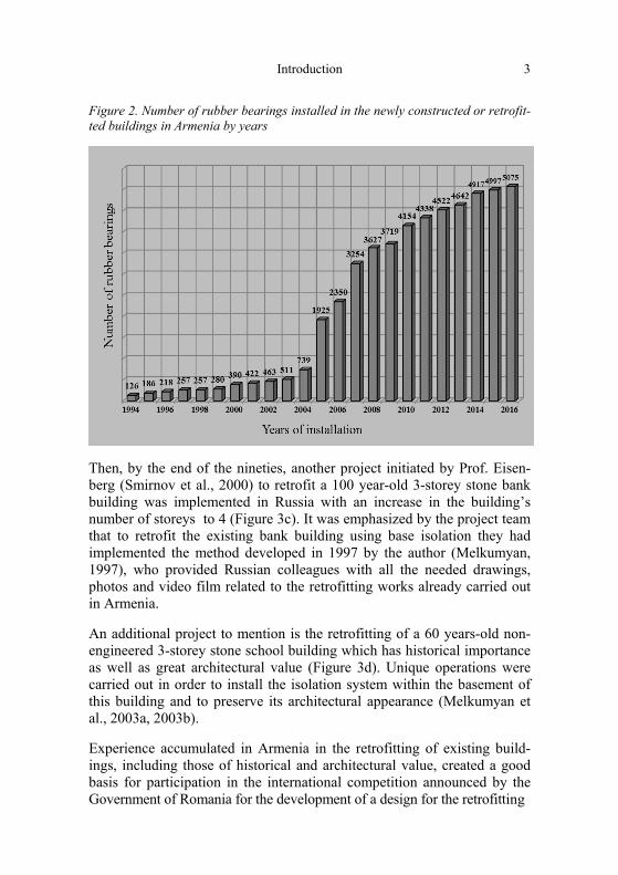
The number of seismically isolated buildings per capita in Armenia is among the highest in the world. Alongside this, seismic isolation laminat-ed rubber-steel bearings (SILRSBs) differing by shape and dimension as well as by damping (low, medium and high) have been designed, and more than 5000 SILRSBs were manufactured in the country, tested locally, and applied in construction (Figure 2).
Thus, by creating the above-mentioned seismic retrofitting technologies and implementing them in different existing buildings the author has accumulat-ed rich experience, which is shared below in the account of several remarka-ble projects. One of them is the retrofitting by base isolation of a 5-storey stone apartment building (Figure 3a) in Armenia. The operation was made without the resettlement of the occupants (Melkumyan, 1997). World prac-tice provides no similar precedent in the retrofitting of apartment buildings.
The next development of the technology was to utilize the newly devel-oped method of an additional isolated upper floor (AIUF) acting as a vi-bration damper. This technology of roof isolation was used in earthquake protection design and implemented in two existing reinforced concrete (R/C) 9-storey standard design frame buildings (Figure 3b), also in Arme-nia (Melkumyan, 2007).
Introduction
3
Figure 2. Number of rubber bearings installed in the newly constructed or retrofit-ted buildings in Armenia by years
Then, by the end of the nineties, another project initiated by Prof. Eisen-berg (Smirnov et al., 2000) to retrofit a 100 year-old 3-storey stone bank building was implemented in Russia with an increase in the building’s number of storeys to 4 (Figure 3c). It was emphasized by the project team that to retrofit the existing bank building using base isolation they had implemented the method developed in 1997 by the author (Melkumyan, 1997), who provided Russian colleagues with all the needed drawings, photos and video film related to the retrofitting works already carried out in Armenia.
An additional project to mention is the retrofitting of a 60 years-old non-engineered 3-storey stone school building which has historical importance as well as great architectural value (Figure 3d). Unique operations were carried out in order to install the isolation system within the basement of this building and to preserve its architectural appearance (Melkumyan et al., 2003a, 2003b).
Experience accumulated in Armenia in the retrofitting of existing build-ings, including those of historical and architectural value, created a good basis for participation in the international competition announced by the Government of Romania for the development of a design for the retrofitting

Chap
ter O
ne
4 Fi
gure
3. P
roje
cts
on r
etro
fittin
g by
bas
e an
d ro
of is
olat
ion
utili
zing
diff
eren
t sei
smic
isol
atio
n st
rate
gies
and
impl
emen
ted
in A
rme-
nia
and
Russ
ia o
r, to
be
impl
emen
ted
in R
oman
ia
a.
b.
c.
d
. e.

Introduction
5
of a 180-year old 3-storey historical building (the Iasi City Hall) by base isolation (Figure 3e). The structural concept, including a new approach to installing seismic isolation rubber bearings, was developed and the design of the retrofitting was accomplished in cooperation with the Romanian company, MIHUL S.R.L. (Melkumyan et al., 2011, Melkumyan, 2011).
Based on the experience gained, the new and unique seismic isolation strategies, structural concepts and technologies were developed, providing earthquake safety for the existing buildings (Melkumyan, 2014a). This book consists of two main parts: the first of them is dedicated to the con-cept of dampers for the earthquake protection of existing buildings, the study of their efficiency, the theoretical background, experimental investi-gations and implementation in the form of roof isolation and other damper systems; and the second part is dedicated to the concepts of retrofitting by base isolation and their implementation in different types of existing frame and stone buildings.
In the first part of the book, together with the two above-mentioned exist-ing buildings protected by an AIUF, a new structural concept of earth-quake protection by roof isolation (Melkumyan, 2014b), designed for application in the existing 12-storey R/C office building erected in 1995, is described. The top floor of this building is an attic, the slab of which had to be separated from the columns, and then lifted up and SILRSBs, with high damping of about 15%, installed between them. There was a need to increase the damping, something that was achieved by a special measure which, together with the sizes and physical/mechanical parameters of the applied SILRSBs, will be presented in this book. Thus, the aforementioned slab is converted into an isolated upper slab which subsequently acts as a tuned mass damper, protecting the building from strong seismic events.
Dampers could also be applied to a base isolated structure in order to re-strict an overall displacement of the isolation system. In such a case, the damper must be attached immediately at the level of this system. Howev-er, supplementary damping to reduce the displacement demand on the iso-lation system may increase the in-structure accelerations (Kelly, 1999). In order to avoid this effect a new type of damper to restrict the displace-ments of seismically isolated buildings called a Dynamic Damper (DD) was developed and proposed by the author (Melkumyan, 2000). The name “dynamic damper” or “dynamic absorber” is applied when the auxiliary mass system has little damping (Reed, 1961). It is suggested to use, as the mass of the DD, the perimeter pavement around the building which is sep-arated from the superstructure and hung to it by means of laminated rubber

Chapter One
6
bearings. Other types of DD are also considered. The stiffness and mass of the DD should be chosen such that the period of vibration of the DD is equal to that of the isolated building. Such a damper will allow us to de-crease the horizontal displacements and also to simplify the isolation sys-tem itself. The suggested structural system of the DD also increases the overturning resistance of the isolated building (Melkumyan, 2000, Tanigu-chi et al., 2008).
In the second part of the book new strategies for retrofitting by base isola-tion are described. One of these relates to a 55 year-old 4-storey R/C in-dustrial frame building, which had to be simultaneously reconstructed into a 6-storey hotel building (Melkumyan, 2014c). Principally, new structural approaches have been proposed for the seismic isolation of the building’s R/C bearing frame, and also innovative new technology for retrofitting by base isolation was developed and applied to this building. SILRSBs with high damping of about 15% were used. However, these bearings are dif-ferent than those mentioned above for the 12-storey office building. Crea-tive solutions are proposed for the first time, and envisage placing the seismic isolators around the existing columns and then gradually cutting these structural elements. Operations are designed to be performed for the existing columns in several stages.
Further developments have also taken place for retrofitting by base isola-tion, but in contrast to the above-mentioned frame building, the new struc-tural solution and technology were suggested for an R/C braced-frame building. Unique operations for the retrofitting of the 8-storey Hematology Center Hospital Building (HCHB) (Melkumyan, 2014d, Melkumyan, 2015) constructed about 45 years ago are also described. The seismic isolation of this building is planned to be implemented at the basement level. SILRSBs of the same type as for the 4-storey R/C industrial building were used. Detailed descriptions of all phases for cutting the columns and shear walls, and placing the seismic isolators of the same sizes and physical/mechanical parameters are given in the book.
The second part of the book is also focused on the retrofitting design of an existing stone college building constructed in 1950, and another damaged stone school building constructed in 1959. The structural concepts of ret-rofitting by base isolation developed for these buildings on the basis of the acquired experience are presented. At the same time, special attention is given to the strengthening, by R/C jackets, of the damaged parts of the existing stone load-bearing walls. It is mentioned that there is no basement in most of the area under the school building, the basement existing only

Introduction
7
under a part of the building. Therefore, in order to efficiently implement an isolation system, the creative solution envisages an extension of the basement throughout the whole built surface of the building.
Earthquake response analyses for all the above-mentioned buildings were carried out by the Armenian Seismic Code and acceleration time histories and their detailed results are given in the book.
References
Kelly, J. (1999). The role of damping in seismic isolation. Earthquake Engineering & Structural Dynamics, no.28, 3-20.
Melkumyan, M. (1997). The use of high damping rubber isolators to up-grade earthquake resistance of existing buildings in Armenia. Interna-tional Post-SMiRT Conference Seminar on Seismic Isolation, Passive Energy Dissipation and Active Control of Seismic Vibrations of Struc-tures, Taormina, Sicily, Italy, 861-867.
Melkumyan, M. (2000). The state of the art in structural control in Arme-nia and proposal on application of the dynamic dampers for seismically isolated buildings. Third International Workshop on Structural Control, Paris, France, 365-373.
Melkumyan, M., Käppeli, G., Khalatyan, R., & Hovivyan, H. (2003a). Application of seismic isolation for retrofitting of existing 3-storey stone building of the school #4 in the city of Vanadzor, Armenia, 8th World Seminar on Seismic Isolation, Energy Dissipation and Active Vibration Control of Structures, Yerevan, Armenia, 557-565.
Melkumyan, M., Hovivyan, H., Movsessyan, L., & Terjanyan, S. (2003b). Technique of installation of seismic isolation bearings in an existing building with historical and architectural value, 8th World Seminar on Seismic Isolation, Energy Dissipation and Active Vibration Control of Structures, Yerevan, Armenia, 629-641.
Melkumyan, M. (2007). Base and roof isolation for earthquake retrofitting and protection of existing buildings in Armenia, International Sympo-sium on Seismic Risk Reduction (the JICA Cooperation Project in Romania), Bucharest, Romanian, 593-600.
Melkumyan, M., Mihul, V., & Gevorgyan, E. (2011). Retrofitting by base isolation of existing buildings in Armenia and in Romania and com-parative analysis of innovative vs. conventional retrofitting, 3rd Inter-national Conference on Computational Methods in Structural Dynamics and Earthquke Engineering, Corfu Island, Greece, Paper No. 121.

Chapter One
8
Melkumyan, M. (2011). New solutions in seismic isolation, Yerevan, LUSABATS.
Melkumyan, M. (2014a). Innovative seismic isolation technologies and new structural solutions developed in Armenia for construction of new and retrofitting of existing buildings. “MENSHIN” Journal of Japan Society of Seismic Isolation, no.83, 33-48.
Melkumyan, M. (2014b). New application of roof isolation system in the form of an isolated upper slab for seismic protection of an existing 12-storey office building, International Journal on Civil Engineering & Urban Planning, vol.1, no.1, 1-14.
Melkumyan, M. (2014c). New structural concept for an existing 4-storey reinforced concrete industrial frame building to be retrofitted by base isolation and simultaneously reconstructed into a 6-storey hotel build-ing, Engineering & Technology. J., vol.1, no.1, 1-12.
Melkumyan, M. (2014d). Seismic isolation retrofitting experience in Ar-menia and new structural concept for an existing 8-storey reinforced concrete hospital building to be retrofitted by base isolation, Study of Civil Engineering and Architecture. J., vol.3, 78-92.
Melkumyan, M. (2015). Unique retrofitting technology for base isolation of an existing 8-storey R/C Hematology Center hospital frame building with shear walls, Journal of Civil Engineering and Architecture Re-search, vol.2, no.12, 1153-1162.
Naeim, F., & Kelly J. (1999). Design of seismic isolated structures. From theory to practice, John Wiley & Sons Inc.
Reed, F. (1961). Dynamic vibration absorbers and auxiliary mass dampers. In C.M. Harris and Ch.E. Crede (eds), Shock and Vibration Handbook. McGraw-Hill, 6-1- 6-38.
Smirnov, V., Eisenberg, J., Zhou, F., Chung, Y., & Nikitin, A. (2000). Seismoisolation for upgrading of an existing historical building in Ir-kutsk-City, Siberia-Russia. 12th World Conference on Earthquake En-gineering, Auckland, New Zealand, Paper No. 0962.
Taniguchi, T., Der-Kiureghian, A., & Melkumyan, M. (2008). Effect of tuned mass damper on displacement demand of base-isolated structures. Engineering Structures no.12(30), 3478-3488.

CHAPTER TWO
CONCEPTS OF DAMPERS FOR THE EARTHQUAKE PROTECTION
OF EXISTING BUILDINGS AND FOR DISPLACEMENT RESTRAINTS IN SEISMICALLY ISOLATED BUILDINGS
2.1. Study of the Efficiency of a Tuned Single and Double Mass Damper on a Model of a Frame
Building under Vibration Tests
There are a rather large number of studies concerned with the theoretical investigation of the behavior of buildings with tuned mass dampers under various impacts (Nawrotzki, 2003, Palazzo et al., 2004, Fujitani & Saito, 2006, Taniguchi et al., 2008), however, the experimental studies in this area are quite limited. Melkumyan (1996, 1998, 2007, 2011) has described two works implemented through vibration tests on Series 111 nine-storey full-scale residential buildings equipped with tuned mass dampers in the form of a flexible upper floor (FUF) and an isolated upper floor (IUF) in Vanadzor city, Armenia.
The work presented in this chapter to a certain extent fills the gap in exper-imental studies investigating the behavior of buildings with tuned mass dampers. The studies have been conducted on a model of the same Series 111 nine-storey frame building. The author designed and made the model out of reinforced concrete on a scale of 1:5 (Melkumyan, 1993), using the principle of simple similarity developed in 1965 (Nazarov, 1965). It had nine columns forming two 120cm spans in mutually perpendicular direc-tions, with axial dimensions of 240x240cm. In one of the directions, the spatial stiffness of the model was provided by three frames with strong load-bearing beams (frame design), and in the other – by three frames with weak binding beams and a single shear wall located in one of the spans in the plane of the middle frame (braced-frame design). The cross-sections of

Chapter Two
10
the columns were 8x8cm, those of the bearing beams – 8х10.4(h)cm and the binding beams – 8х5(h)cm. The floors consisted of prefabricated hol-low-core model slabs with a thickness of 4.4cm, whereas the prefabricated panels of the shear wall were 2.8cm thick. In accordance with the structur-al concept of the Series 111 buildings, the shear wall panels were connect-ed to columns by welding the embedded items, and their connection to the beams was provided by casting concrete over the dowels protruding from the shear wall prefab panels. The total height of the model was 5.9m, with each storey being 0.6m high; the foundation beams were 0.4m high and the column steel caps extended beyond the 9th storey slab by 0.1m.
A general view of the model, before the placement of the tuned mass dampers, is shown in Figure 1. As seen, cast iron weights were suspended from the model’s slabs to provide vertical loads for creating the necessary level of stress-strain state in the structural elements of the model. More detailed information on the design, construction and testing of this model, without tuned mass dampers, can be found in other publications of the author, and not provided here for brevity.
Before placing the tuned mass dampers, the model vibrations were in-duced in both directions by laboratory vibration machines specially devel-oped and made by the author for model tests. The vibration machines were placed on the 9th storey’s slab and rigidly connected to a steel frame, which in turn was welded to the steel caps of all nine columns of the mod-el (Figure 2). The vibration machines were mounted in such a manner that the exciting forces created during the rotation of the weights eccentrically placed on the vibrators shafts acted on the vertical planes, passing in mu-tually perpendicular directions through the middle axes (frames) of the model. The revolutions of the vibration machines’ DC motors were con-tinuously variable with the help of a special device, thus providing har-monic vibrations in the range from 0 to 10Hz. The parameters of the forced vibrations were measured by large displacement seismographs, as well as accelerographs placed at the level of all floors along the central vertical axis of the model, with the exception of the devices on the 9th floor, where they were placed outside the central zone of the model’s plan, as it was occupied by the vibration machines.

Concepts of Dampers for the Earthquake Protection of Existing Buildings 11
Figure 1. Series 111 nine-storey frame building model designed and constructed on a scale of 1:5;
a – front view, b – side view
a.
b.
Vibration tests on the Series 111 nine-storey full-scale frame buildings equipped with tuned mass dampers in the form of FUF or IUF have been mentioned above. Those systems were single mass dampers. Conversely, the subject of this experimental work was the tuned double mass damper. Prior to mounting such damper, as an additional tenth floor, the dynamic characteristics of the model (periods and damping ratios) had been deter-mined. The vibration machine was used to induce forced resonant vibra-tions of 1st, 2nd and 3rd modes. The values of periods and damping ratios calculated, based on the records of these vibrations, are indicated in Table 1.

Chapter Two
12
Figure 2. Laboratory vibration machines for testing large models, placed on the slab of the 9th storey (before mounting the dampers) with a steel frame rigidly fixed to the steel caps of the nine-storey frame building model columns
Table 1. Periods of oscillations and damping ratios of the nine-storey frame building model at the stage of elastic behavior under the first three modes of resonant vibrations, prior to mounting the tuned double mass damper
Direction of the tests
Periods of oscillations, sec Damping ratio , %
For the 1st mode Т1
For the 2nd mode Т2
For the 3rd mode Т3
Along the frames with strong bear-ing beams (frame design)
0.326 0.133 0.075 4.3
Along the frames with weak bind-ing beams and shear wall (braced-frame design)
0.280
0.088
0.049
4.0

Concepts of Dampers for the Earthquake Protection of Existing Buildings 13
The experimental studies of the nine-storey frame building model with a tuned double mass damper were intended to be carried out under its load-ing only in the direction of the frames with weak binding beams and the shear wall located in one of the spans of the plane of the middle frame. Given this circumstance, one of the vibration machines was dismantled. In order to reach the cracking stage, in the mentioned direction, the model was subjected to several phases of dynamic loading with a gradual in-crease in the mass of the off-center weights on the vibrator shafts. In these conditions the shear wall panels suffered light damage in the form of in-clined, intersecting thin cracks; whereas the fundamental period of oscilla-tions increased by 1.25 times compared to the initial one and equaled 0.35sec (1=2.86Hz). Almost no change of the damping ratio was ob-served (=4%), while the 9th storey’s floor displacement amplitude was А=3.1cm.
The obtained values served as a basis for choosing the mass and stiffness parameters of the first damper, which was named as “the main” by the author. As it turned out, the necessary horizontal stiffness of the men-tioned additional tenth storey, i.e. the tuned mass damper, could be achieved by using square iron posts with a cross-section of 14x14mm, welded to the sides of the steel caps of the nine-storey frame building model’s columns. The stiffness of the model’s main damper ceiling could be ensured by 45x45x4mm L-shaped rolled steel profiles, whereas the mass could be accumulated by R/C plates placed on these profiles (Figure 3). Thus, the design of the main damper created on the nine-storey model is similar to that of the FUF, the design of which has been developed by the author, and later implemented and tested with his direct participation (Melkumyan, 1998, Minassian et al., 1993).
These studies were aimed at determining the efficiency and damping prop-erties of the tuned double mass damper as compared to those of a single mass damper. The question of optimal damping in the main damper was not dealt with. The main damper’s tuning f2
1=f2MD÷2
1 (with no considera-tion of damping (Korenev & Reznikov, 1981)) was performed immediate-ly on the damper. Initially, the main damper was tuned to the fMD frequency, very close to the resonance frequency 1 of the model’s 1st mode oscillations. Afterwards, using incremental changes in the damper’s mass, the optimal tuning (Yoshizumi et al., 2003) was determined at which the maximum efficiency of damping was achieved. It turned out that the optimal tuning requires the main damper’s mass accumulation up to the value of mMD=360kg, which is half of the model’s single storey weight (without kentledge) mstorey=720kg. Hence, given that total mass of the

Chapter Two
14
model’s nine stories, is МM=720x9=6480kg, then the relative mass is =mMD÷МM=360÷6480=0.056 (or 5.6%), and the tuning f2
1=1.0.
Figure 3. Fragment of the nine-storey model’s upper part with a view of the addi-tional tenth storey, i.e. the main damper together with placed R/C plates that con-stitute its mass
The approach that takes into account the damping, through the optimiza-tion of the parameters for tuned mass dampers, differs from the case for dampers without damping, since the optimal values of tuning and relative viscous (or inelastic) resistance for a given value of are the ones to be determined. The optimal values of tuning for the hypotheses of viscous resistance or internal inelastic resistance are determined in the same way (Korenev & Reznikov, 1981, Warburton, 1982). In our case the optimal tuning, with consideration of damping, differs from the f2
1 value and is determined by the following formula:
95.0056.11
112
оpf

Concepts of Dampers for the Earthquake Protection of Existing Buildings 15
Once the main damper was tuned, it was subjected to dynamic loading with a variable frequency. Figure 4a shows fragments of vibration records obtained by the seismographic instrumentation at the slab of the model’s ninth storey and at the level of main damper’s top. It was derived from the obtained records that the maximum oscillation amplitude of the model’s upper part with the main damper is 1.05cm, which is almost 3 times less (Makino et al., 2009, Shooshtari & Afzali, 2010) than the comparative oscillation amplitude of the model’s upper part without a damper (3.1cm). The maximum oscillation amplitudes of the model’s upper part with the damper were approximately the same before and after passing through resonance, and corresponded to frequencies of 2.5Hz and 3.3Hz, which are almost symmetrical in relation to the resonant frequency of the model without a damper (2.86Hz). It has to be noted that before passing through resonance the damper acted in the same phase with the model, whereas after passing through resonance it acted in anti-phase relative to the model. The main damper oscillation amplitude was about 3-4 times larger than the amplitudes of the model’s upper part oscillation. The free oscillations of the optimally tuned main damper have also been recorded (Figure 4b). The damping ratio of the main damper determined from this record was =0.7%.
Upon completion of the model testing with the main damper, a second weight was added to its ceiling and hence, the single mass damper was turned into a double mass one. The second mass of the damper could be accumulated by weights placed in a 30х40х10cm metallic box weighing 10kg. The metallic box was suspended from the main damper’s ceiling by round steel rods with a diameter of 8mm and length of 30cm. The general view of the second suspended mass is shown in Figure 5.

Chapter Two
16
Figure 4. Fragments of vibration records at the top of the nine-storey model with a single mass damper (1) and at the level of the damper’s top (2) under dynamic loading created by vibration machine (a), as well as fragment of the single mass damper’s normal mode oscillations record (b)

Concepts of Dampers for the Earthquake Protection of Existing Buildings 17
Figure 5. Fragment of the nine-storey model’s upper part with the view of the sec-ond mass created by weights placed in a metallic box and suspended from the main damper
The tuning, or in other words, selection of the optimal value for the second mass was performed in the same manner as the tuning of the main damper. At the optimal tuning the weight for the second mass of the damper turned out to be 40kg, and the partial frequency of its normal mode was 2.65Hz. The relative masses and tunings of the double mass damper were, respec-tively:
11.036040;93.0;0.1
;0617.07209
40360
1
22
22
21
21
d
d
M
ddd
mm
ff
Mmm
The total mass of the double mass damper turned out to be 11% higher than that of the single mass damper. Over the course of the tuning of the created damper system, control records of model oscillations with the double mass damper were obtained, again under harmonic impact with variable frequencies. The records of these oscillations are provided in Fig-ure 6. These records, along with the ones shown in Figure 4, were used to

Chapter Two
18
Figure 6. Fragments of vibration records at the top of the nine-storey model with a double mass damper (1) and at the level of the damper’s top (2) under dynamic loading created by vibration machine (a), as well as fragment of the double mass damper’s normal mode oscillations record (b)

Concepts of Dampers for the Earthquake Protection of Existing Buildings 19
derive the amplitude-frequency characteristics of the model (Figure 7). The obtained results indicate that the tuned double mass damper is more efficient than the single one, since the damping coefficient for the double mass damper reaches 4.4, which is 46.7% higher than that of the single mass damper. Moreover, the range of the frequencies damped is about 50% wider. These results somewhat exceeded our expectations.
Comparing Figures 4 and 6, one may notice that the oscillation amplitudes of the main damper have significantly decreased. Before adding the sec-ond mass, the maximum amplitude of the tuned single mass damper was around 3.5cm, whereas after adding the second mass it decreases to 1.4cm. Normal mode oscillation records showed that its damping ratio is =1.75%, i.e. 2.5 times larger as compared to that of the single mass damper. Appar-ently, the increased damping effect of the tuned double mass damper is explained by the mutual influence of the main damper and the second mass suspended from it, whereby the energy of oscillations is re-distributed. Thus, it was discovered that, under harmonic oscillations in-duced by a vibration machine, the tuned double mass damper had a higher efficiency than the single one.
Summarizing all of the above, it can be stated that the experimental studies conducted confirm the rather high efficiency of tuned mass dampers, and, thus, that they are undoubtedly worth using to increase the seismic re-sistance of buildings and structures (Chang et al., 2009, Dorka, 2000). The question of using one or another type of damper depending on the number of masses (single, double or multi-mass), or on structural schemes (FUF or IUF, etc.) at the top of actual buildings is to be addressed. The many fac-tors involved include: the number of storeys, the structural concept and technical condition of the buildings, any circumstances that limit the damper movement, the necessity of utilizing the space inside the damper, the cost effectiveness of the damper, etc.

Chapter Two
20
Figure 7. Amplitude-frequency characteristics of the nine-storey model: (1) without damper; (2) with the single mass damper; and (3) with the double mass damper
2.2. Theoretical Background: Linear and Non-Linear Analyses of a Building with and without TMD
One of the major features of the anti-seismic design of buildings is the possibility of controlling the inertial load values, depending on the struc-tural concept of the buildings. In the 1950s, when the spectral theory of seismic stability was developed, the flexible ground floor was regarded as the basis for reducing the seismic action level. However, the consequences of strong earthquakes such as the 1963 Skopje, the 1988 Spitak or the 2008 Sichuan Earthquakes, etc. have shown that in this case the bearing structures (mainly columns) of the ground floors were severely damaged and further use of buildings was impossible despite the upper floors being well preserved. Therefore, continuing efforts have been made by research-ers to discover the most efficient methods of seismic protection for build-

Concepts of Dampers for the Earthquake Protection of Existing Buildings 21
ings and structures, and their practical application. One such method is the TMD, known as a passive vibro-protecting device. A TMD is basically a single-degree-of-freedom appendage of the primary structure (Warburton, 1982). Such dampers have been widely investigated in connection with seismic protection problems (Nawrotzki, 2003, Palazzo et al., 2004, Hu-mar & Wright, 1977, Pinkaew & Lukkunaprasit, 1999).
The natural frequency of a TMD (with the damping neglected) should be equal to the forced vibration frequency of the structure to be protected, which as a rule is represented in the form of a single-degree-of-freedom system. However, during earthquakes, forced vibrations are neither har-monic, nor do they have a preset frequency; while buildings are not single-degree-of-freedom systems. As it is mentioned in Melkumyan (2011), in spite of the chaotic nature of the ground motion, the acceleration time his-tories of linear oscillators are similar to harmonic vibration processes, with the period equal to that of linear oscillators. Therefore, if the first vibration mode is assumed to be the most significant one during earthquakes, then the natural frequency of the damper should be equal to the first mode fre-quency of the structure’s vibration. When seismic loading is formed due to the superposition of inertial loadings of the first three oscillation modes, then three dampers should be used instead of one, with natural vibration frequencies tuned correspondingly to frequencies of the first three modes of the building’s free vibrations.
Thus, in the most general case, the application of several dampers is expe-dient in terms of reducing the seismic action level in buildings. However, it is technologically difficult to design and make them in the traditional way, that is, in the form of a mass properly fixed to the building. More specifically, even one such damper (for the first vibration mode) in a 10-12 storey building possesses considerable mass, and its practical realiza-tion is impossible. Therefore, an additional upper floor for the building has been proposed as a vibration damper (Melkumyan, 2011).
As the mass of the upper floor would be approximately equal to the mass of other floors of the building, this additional floor should exhibit less stiffness than that of the other floors. Thus, a building with a flexible up-per floor would be analogous to one with a flexible ground floor. However, there is an essential difference between the two since, after a seismic event, residual deformations in the flexible upper floor are not disastrous for the building as a whole. A flexible upper floor (TMD) could be erected on the existing buildings to increase their seismic resistance, without requiring the tenants to leave the building. Also, a TMD could be widely applied in

Chapter Two
22
new construction.
Determination of the damper parameters essentially depends on the nature of the seismic action. The first attempt to find the optimal parameters of an additional upper tenth floor in a Series 111 nine-storey building with R/C bearing frames and shear walls using accelerograms of various earth-quakes is presented below. To simplify the problem, the building design model including the TMD at this first attempt is assumed to be a cantilever beam with masses concentrated at the floor levels. The equations of the forced vibrations of such a system are given by the formula:
,011111110 kkkkkkkkkkkkkkkk yyayyayyayyayym k = 1, 2, …n; y0 = 0; an+1 = 0; n = 10,
where: mk, ak, yk are the mass, stiffness and displacement of the kth floor of the building, mr=m10, ar=a10, yr=y10 are the mass, stiffness and displace-
ment of the damper (the additional flexible upper 10th floor), /k is
the coefficient of viscous damping of the kth floor, and )(0 ty is the ground acceleration (accelerogram).
The values of a floors’ stiffness and the mass of the investigated building
are as follows: a1=a2=…=a9=897000kN/m; m1=m2=…=m8=360 mskN 2
;
m9=430 mskN 2
. Using this data (at k=0) and the assumed simplified design model, the periods of the first three vibration modes of the building in the direction of shear walls without TMD were obtained: T1=0.778s, T2=0.261s, T3=0.159s. The values of vibration periods of the first three modes for a building with TMD are given in Table 2, where =mr/m1, d=ar/a1 (Melkumyan, 2011).