Embed Size (px)
Citation preview
7/30/2019 earthquake resistant structure
http://slidepdf.com/reader/full/earthquake-resistant-structure 1/13
IFET COLLEGE OF ENGINEERING
VILLUPURAM
Earthquake Resistantstructure
PREPARED BY:
SHANMUGAVEL.R
CIVIL ENGG(IVYEAR)
1

7/30/2019 earthquake resistant structure
http://slidepdf.com/reader/full/earthquake-resistant-structure 2/13
ABSTRACT:
Throwing light towards“Earthquake Resistant structure” is the
ultimate goal of our paper. The most
pronounced fact is that “Buildings are
the Worst Killers than the Earthquake”.Unlike the past when the earthquakes
were rare, now India and other parts of
the world are prone to frequent earthquakes. Neglecting earthquake hazards
in the design of buildings will not be fair design.
So we aimed at projecting theapplicable techniques in design of a
structure, which can sustain against the
seismic waves, which roots fromEarthquake. At first we commence with
earthquake analysis grasping the method
of dynamic analysis through time historyand response spectrum method.
The path leads to causes of Earthquake,
transfer of seismic waves into the
structure. Advance techniques concernedwith the structural elements such as
beams, columns, beam column integrity,
boundary elements have been discussed.
In this paper we are going to explainthe advance earthquake resistant
techniques and also explained about the
techniques how to control the damage of structure during an earth quake. The
following techniques are effectively used
in building, bridges and other structures
such as damper, bearing, bracing andsome of the other structural syste
The above technique working principleand uses are explain about this paper.
These techniques control the damage
and increase the structural life.
INTRODUCTION
Seismic retrofitting is the
modification of existing structures tomake them more resistant to seismic
activity, ground motion, or soil failuredue to earthquakes. With better
understanding of seismic demand onstructures and with our recent
experiences with large earthquakes near
urban centers, the need of seismicretrofitting is well acknowledged. Prior
to the introduction of modern seismic
codes in the late 1960s for developedcountries (US, Japan etc.) and late 1970s
for many other parts of the world
(Turkey, China etc.), many structureswere designed without adequatedetailing and reinforcement for seismic
protection. Whilst current practice of
seismic retrofitting is predominantlyconcerned with structural improvements
to reduce the seismic hazard of using the
structures, it is similarly essential toreduce the hazards and losses from non-
structural elements.
Strategies
Retrofit strategies are different
from retrofit techniques, where theformer is the basic approach to achieve
an overall retrofit performance objective,
such as increasing strength, increasingdeformability, reducing deformation
2

7/30/2019 earthquake resistant structure
http://slidepdf.com/reader/full/earthquake-resistant-structure 3/13
demands while the latter is the technical
methods to achieve that strategy.
• Increasing the global capacity(strengthening). This is typically
done by the addition of cross braces or new structural walls.
• Reduction of the seismic demand by means of supplementary
damping and/or use of base
isolation systems.
• Increasing the local capacity of structural elements. These
strategies recognize the inherent
capacity within the existingstructures, and therefore adopt a
more cost-effective approach to
selectively upgrade local
capacity (deformation/ductility,strength or stiffness) of
individual structural components.
• Selective weakening retrofit.This is a counter intuitive
strategy to change the inelastic
mechanism of the structure,whilst recognizing the inherentcapacity of the structure.
Performance objectives
In the past, seismic retrofit was primarily applied to achieve public
safety, with engineering solutions
limited by economic and politicalconsiderations. However, with the
development of Performance based
earthquake engineering (PBEE), several
levels of performance objectives aregradually recognized:
• Public safety only. The goal is to
protect human life, ensuring that
the structure will not collapseupon its occupants or passersby,
and that the structure can be
safely exited. Under severeseismic conditions the structure
may be a total economic write-
off, requiring tear-down andreplacement.
• Structure survivability. The
goal is that the structure, while
remaining safe for exit, mayrequire extensive repair (but not
replacement) before it is
generally useful or consideredsafe for occupation. This is
typically the lowest level of
retrofit applied to bridges.
• Structure functionality. Primarystructure undamaged and the
structure are undiminished in
utility for its primary application.
A high level of retrofit, thisensures that any required repairs
are only "cosmetic" - for example, minor cracks in plaster ,drywall and stucco. This is the
minimum acceptable level of
retrofit for hospitals.
• Structure unaffected. This levelof retrofit is preferred for historic
structures of high cultural
significance.
Techniques
Common seismic retrofitting techniques
fall into several categories:
3

7/30/2019 earthquake resistant structure
http://slidepdf.com/reader/full/earthquake-resistant-structure 4/13
External post-tensioning
The use of external post-
tensioning for new structural systemshas been developed in the past decade.
Under the PRESS (Precast SeismicStructural Systems), a large-scale
U.S./Japan joint research program,unbonded post-tensioning high strength
steel tendons have been used to achieve
a moment-resisting system that has self-centering capacity. An extension of the
same idea for seismic retrofitting has
been experimentally tested for seismicretrofit of California bridges under a
Caltrans research project and for seismic
retrofit of non-ductile reinforcedconcrete frames. Pre-stressing can
increase the capacity of structural
elements such as beam, column and
beam-column joints. It should be notedthat external pre-stressing has been used
for structural upgrade for gravity/live
loading since 1970s.
Base isolators
Base isolation is a collection of structural elements of a building that
should substantially decouple the building's structure from the shaking
ground thus protecting the building's
integrity and enhancing its seismic
performance. This earthquake engineering technology, which is a kind
of seismic vibration control, can be
applied both to a newly designed building and to seismic upgrading of
existing structures. Normally,
excavations are made around the building and the building is separated
from the foundations. Steel or reinforced
concrete beams replace the connections
to the foundations, while under these, theisolating pads, or base isolators, replace
the material removed. While the base
isolation tends to restrict transmission of
the ground motion to the building, it also
keeps the building positioned properlyover the foundation. Careful attention to
detail is required where the building
interfaces with the ground, especially atentrances, stairways and ramps, to
ensure sufficient relative motion of those
structural elements.
Supplementary dampers
Supplementary dampers absorb
the energy of motion and convert it to
heat, thus "damping" resonant effects in
structures that are rigidly attached to the
ground. In addition to adding energydissipation capacity to the structure,
supplementary damping can reduce thedisplacement and acceleration demand
within the structures. In some cases, the
threat of damage does not come from theinitial shock itself, but rather from the
periodic resonant motion of the structure
that repeated ground motion induces. In
practical sense, supplementary dampersact similarly to Shock absorbers used in
automotive suspensions.
Tuned mass dampers
Tuned mass dampers (TMD)employ movable weights on some sort of
springs. These are typically employed to
reduce wind sway in very tall, light buildings. Similar designs may be
employed to impart earthquake
resistance in eight to ten story buildings
that are prone to destructive earthquakeinduced resonances.
Slosh tank
A slosh tank is a large tank of
fluid placed on an upper floor. During aseismic event, the fluid in this tank will
4

7/30/2019 earthquake resistant structure
http://slidepdf.com/reader/full/earthquake-resistant-structure 5/13
slosh back and forth, but is directed by
baffles - partitions that prevent the tank
itself becoming resonant; through itsmass the water may change or counter
the resonant period of the building.
Additional kinetic energy can beconverted to heat by the baffles and is
dissipated through the water - any
temperature rise will be insignificant
Active control system
Very tall buildings when built
using modern lightweight materials
might sway uncomfortably but not
dangerously in certain wind conditions.
A solution to this problem is to includeat some upper story a large mass,
constrained, but free to move within alimited range, and moving on some sort
of bearing system such as an air cushion
or hydraulic film. Hydraulic pistons, powered by electric pumps and
accumulators, are actively driven to
counter the wind forces and natural
resonances. These may also, if properlydesigned, be effective in controlling
excessive motion - with or withoutapplied power - in an earthquake. Ingeneral, though, modern steel frame high
rise buildings are not as subject to
dangerous motion as are medium rise(eight to ten storey) buildings, as the
resonant period of a tall and massive
building is longer than theapproximately one second shocks
applied by an earthquake.
Connections between buildings and
their expansion additions
Frequently, building additions
will not be strongly connected to the
existing structure, but simply placed
adjacent to it, with only minor continuity
in flooring, siding, and roofing. As a
result, the addition may have a differentresonant period than the original
structure, and they may easily detach
from one another. The relative motionwill then cause the two parts to collide,
causing severe structural damage. Proper
construction will tie the two buildingcomponents rigidly together so that they
behave as a single mass or employ
dampers to expend the energy from
relative motion, with appropriateallowance for this motion.
Exterior reinforcement of building
Exterior concrete columns
Historic buildings, made of
unreinforced masonry, may haveculturally important interior detailing or
murals that should not be disturbed. In
this case, the solution may be to add anumber of steel, reinforced concrete, or
post stressed concrete columns to the
exterior. Careful attention must be paid
to the connections with other memberssuch as footings, top plates, and roof
trusses
Infill shear trusses
Shown here is an exterior shear
reinforcement of a conventional
reinforced concrete dormitory building.In this case, there was sufficient vertical
strength in the building columns and
5
7/30/2019 earthquake resistant structure
http://slidepdf.com/reader/full/earthquake-resistant-structure 6/13
sufficient shear strength in the lower
stories that only limited shear
reinforcement was required to make itearthquake resistant for this location,
near the Hayward fault.
Typical Retrofit Scenario & Solution
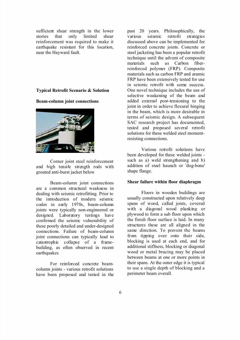
Beam-column joint connections
Corner joint steel reinforcementand high tensile strength rods with
grouted anti-burst jacket below
Beam-column joint connections
are a common structural weakness indealing with seismic retrofitting. Prior to
the introduction of modern seismic
codes in early 1970s, beam-column joints were typically non-engineered or
designed. Laboratory testings have
confirmed the seismic vulnerability of
these poorly detailed and under-designedconnections. Failure of beam-column
joint connections can typically lead tocatastrophic collapse of a frame- building, as often observed in recent
earthquakes
For reinforced concrete beam-
column joints - various retrofit solutionshave been proposed and tested in the
past 20 years. Philosophically, the
various seismic retrofit strategies
discussed above can be implemented for reinforced concrete joints. Concrete or
steel jacketing has been a popular retrofit
technique until the advent of compositematerials such as Carbon fiber-
reinforced polymer (FRP). Composite
materials such as carbon FRP and aramicFRP have been extensively tested for use
in seismic retrofit with some success.
One novel technique includes the use of
selective weakening of the beam andadded external post-tensioning to the
joint in order to achieve flexural hinging
in the beam, which is more desirable in
terms of seismic design. A subsequentSAC research project has documented,
tested and proposed several retrofitsolutions for these welded steel moment-
resisting connections.
Various retrofit solutions have
been developed for these welded joints -such as a) weld strengthening and b)
addition of steel haunch or 'dog-bone'
shape flange.
Shear failure within floor diaphragm
Floors in wooden buildings are
usually constructed upon relatively deep
spans of wood, called joists, covered
with a diagonal wood planking or plywood to form a sub floor upon which
the finish floor surface is laid. In many
structures these are all aligned in thesame direction. To prevent the beams
from tipping over onto their side,
blocking is used at each end, and for additional stiffness, blocking or diagonal
wood or metal bracing may be placed
between beams at one or more points in
their spans. At the outer edge it is typicalto use a single depth of blocking and a
perimeter beam overall.
6

7/30/2019 earthquake resistant structure
http://slidepdf.com/reader/full/earthquake-resistant-structure 7/13
If the blocking or nailing is
inadequate, each beam can be laid flat by
the shear forces applied to the building.In this position they lack most of their
original strength and the structure may
further collapse. As part of a retrofit the blocking may be doubled, especially at
the outer edges of the building. It may be
appropriate to add additional nails between the sill plate of the perimeter
wall erected upon the floor diaphragm,
although this will require exposing the
sill plate by removing interior plaster or exterior siding. As the sill plate may be
quite old and dry and substantial nails
must be used, it may be necessary to pre-
drill a hole for the nail in the old wood toavoid splitting. When the wall is opened
for this purpose it may also beappropriate to tie vertical wall elements
into the foundation using specialty
connectors and bolts glued with epoxycement into holes drilled in the
foundation.
House slid off of foundation
Low cripple wall collapse and
detachment of structure from concretestairway
Single or two story wood-frame
domestic structures built on a perimeter or slab foundation are relatively safe in
an earthquake, but in many structures
built before 1950 the sill plate that sits
between the concrete foundation and the
floor diaphragm (perimeter foundation)
or stud wall (slab foundation) may not be sufficiently bolted in. Additionally,
older attachments (without substantial
corrosion-proofing) may have corrodedto a point of weakness. A sideways
shock can slide the building entirely off
of the foundations or slab.
Often such buildings, especiallyif constructed on a moderate slope, are
erected on a platform connected to a
perimeter foundation through low stud-walls called "cripple wall" or pin-up.
This low wall structure itself may fail in
shear or in its connections to itself at thecorners, leading to the building moving
diagonally and collapsing the low walls.
The likelihood of failure of the pin-up
can be reduced by ensuring that thecorners are well reinforced in shear and
that the shear panels are well connected
to each other through the corner posts.This requires structural grade sheet
plywood, often treated for rot resistance.
This grade of plywood is made without
interior unfilled knots and with more,thinner layers than common plywood.
New buildings designed to resist
earthquakes will typically use OSB(oriented strand board), sometimes with
metal joins between panels, and with
well attached stucco covering to enhanceits performance. In many modern tract
homes, especially those built upon
expansive (clay) soil the building isconstructed upon a single and relatively
thick monolithic slab, kept in one piece
by high tensile rods that are stressedafter the slab has set. This post stressing
places the concrete under compression -
a condition under which it is extremely
strong in bending and so will not crack under adverse soil conditions.
7

7/30/2019 earthquake resistant structure
http://slidepdf.com/reader/full/earthquake-resistant-structure 8/13
Multiple piers in shallow pits
Some older low-cost structures
are elevated on tapered concrete pylonsset into shallow pits, a method
frequently used to attach outdoor decksto existing buildings. This is seen in
conditions of damp soil, especially intropical conditions, as it leaves a dry
ventilated space under the house, and in
far northern conditions of permafrost (frozen mud) as it keeps the building's
warmth from destabilizing the ground
beneath. During an earthquake, the pylons may tip, spilling the building to
the ground. This can be overcome by
using deep-bored holes to contain cast-in-place reinforced pylons, which are
then secured to the floor panel at the
corners of the building. Another
technique is to add sufficient diagonal bracing or sections of concrete shear
wall between pylons
Reinforced concrete column burst
Jacketed and grouted column on left,unmodified on right
Reinforced concrete columns
typically contain large diameter verticalrebar (reinforcing bars) arranged in a
ring, surrounded by lighter-gauge hoops
of rebar. Upon analysis of failures due toearthquakes, it has been realized that the
weakness was not in the vertical bars,
but rather in inadequate strength and
quantity of hoops. Once the integrity of the hoops is breached, the vertical rebar
can flex outward, stressing the centralcolumn of concrete. The concrete then
simply crumbles into small pieces, now
unconstrained by the surrounding rebar.
In new construction a greater amount of hoop-like structures is used.
One simple retrofit is to surround
the column with a jacket of steel plates
formed and welded into a singlecylinder. The space between the jacket
and the column is then filled with
concrete, a process called grouting.Where soil or structure conditions
require such additional modification,
additional pilings may be driven near thecolumn base and concrete pads linking
8

7/30/2019 earthquake resistant structure
http://slidepdf.com/reader/full/earthquake-resistant-structure 9/13
the pilings to the pylon are fabricated at
or below ground level. In the example
shown not all columns needed to bemodified to gain sufficient seismic
resistance for the conditions expected.
Reinforced concrete wall burst
Concrete walls are often used atthe transition between elevated road fill
and overpass structures. The wall is used
both to retain the soil and so enable theuse of a shorter span and also to transfer
the weight of the span directly
downward to footings in undisturbed
soil. If these walls are inadequate they
may crumble under the stress of anearthquake's induced ground motion.
One form of retrofit is to drillnumerous holes into the surface of the
wall, and secure short L-shaped sections
of rebar to the surface of each hole with
epoxy adhesive. Additional vertical andhorizontal rebar is then secured to the
new elements, a form is erected, and an
additional layer of concrete is poured.
This modification may be combinedwith additional footings in excavated
trenches and additional support ledgersand tie-backs to retain the span on the
bounding walls.
Utility pipes and cables: risks
Natural gas and propane supply
pipes to structures often prove especiallydangerous during and after earthquakes.
Should a building move from itsfoundation or fall due to cripple wallcollapse, the ductile iron pipes
transporting the gas within the structure
may be broken, typically at the locationof threaded joints. The gas may then still
be provided to the pressure regulator
from higher pressure lines and so
continue to flow in substantial
quantities; it may then be ignited by a
nearby source such as a lit pilot light or arcing electrical connection.
There are two primary methodsof automatically restraining the flow of
gas after an earthquake, installed on thelow pressure side of the regulator, and
usually downstream of the gas meter.
• A caged metal ball may bearranged at the edge of an orifice.
Upon seismic shock, the ball will
roll into the orifice, sealing it to
prevent gas flow. The ball may
later be reset by the use of anexternal magnet. This device will
respond only to ground motion.
• A flow-sensitive device may be
used to close a valve if the flow
of gas exceeds a set threshold(very much like an electrical
circuit breaker ). This device will
operate independently of seismic
motion, but will not respond tominor leaks which may be
caused by an earthquake.
It appears that the most secureconfiguration would be to use one of
each of these devices in series.
Tunnels
Unless the tunnel penetrates a
fault likely to slip, the greatest danger totunnels is a landslide blocking an
entrance. Additional protection aroundthe entrance may be applied to divertany falling material (similar as is done to
divert snow avalanches) or the slope
above the tunnel may be stabilized insome way. Where only small- to
medium-sized rocks and boulders are
expected to fall, the entire slope may be
9
7/30/2019 earthquake resistant structure
http://slidepdf.com/reader/full/earthquake-resistant-structure 10/13
covered with wire mesh, pinned down to
the slope with metal rods. This is also a
common modification to highway cutswhere appropriate conditions exist.
Underwater tubes
The safety of underwater tubes ishighly dependent upon the soil
conditions through which the tunnel was
constructed, the materials andreinforcements used, and the maximum
predicted earthquake expected, and other factors, some of which may remain
unknown under current knowledge.
Bridge retrofit
Bridges have several failure modes.
Expansion rockers
Many short bridge spans are
statically anchored at one end and
attached to rockers at the other. Thisrocker gives vertical and transverse
support while allowing the bridge span
to expand and contract with temperature
changes. The change in the length of the
span is accommodated over a gap in theroadway by comb-like expansion joints.
During severe ground motion, therockers may jump from their tracks or be
moved beyond their design limits,
causing the bridge to unship from itsresting point and then either become
misaligned or fail completely. Motion
can be constrained by adding ductile or
high-strength steel restraints that are
friction-clamped to beams and designedto slide under extreme stress while still
limiting the motion relative to the
anchorage.
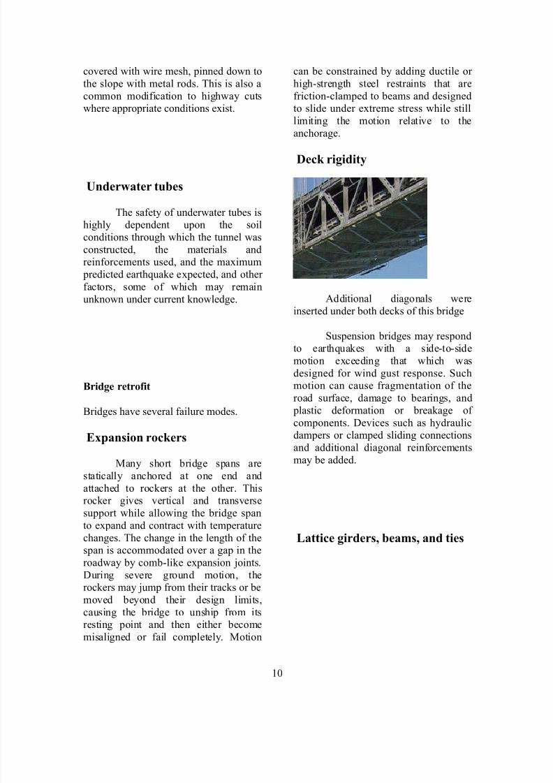
Deck rigidity
Additional diagonals were
inserted under both decks of this bridge
Suspension bridges may respondto earthquakes with a side-to-side
motion exceeding that which was
designed for wind gust response. Suchmotion can cause fragmentation of the
road surface, damage to bearings, and
plastic deformation or breakage of components. Devices such as hydraulicdampers or clamped sliding connections
and additional diagonal reinforcements
may be added.
Lattice girders, beams, and ties
10

7/30/2019 earthquake resistant structure
http://slidepdf.com/reader/full/earthquake-resistant-structure 11/13
Obsolete riveted lattice members
Lattice girders consist of two "I"-
beams connected with a criss-cross
lattice of flat strap or angle stock. Thesecan be greatly strengthened by replacing
the open lattice with plate members.
This is usually done in concert with thereplacement of hot rivets with bolts.
Bolted plate lattice replacement,forming box members
Fill and overpass
Elevated roadways are typically built on sections of elevated earth fill
connected with bridge-like segments,
often supported with vertical columns. If the soil fails where a bridge terminates,
the bridge may become disconnected
from the rest of the roadway and break
away. The retrofit for this is to add
additional reinforcement to anysupporting wall, or to add deep caissons
adjacent to the edge at each end andconnect them with a supporting beam
under the bridge.
Another failure occurs when the
fill at each end moves (through resonant
effects) in bulk, in opposite directions. If
there is an insufficient founding shelf for
the overpass, then it may fall. Additionalshelf and ductile stays may be added to
attach the overpass to the footings at one
or both ends. The stays, rather than being fixed to the beams, may instead be
clamped to them. Under moderate
loading, these keep the overpasscentered in the gap so that it is less likely
to slide off its founding shelf at one end.
The ability for the fixed ends to slide,
rather than break, will prevent thecomplete drop of the structure if it
should fail to remain on the footings.
Residential retrofit.
Wood frame structure
Predominantly
residential/dwelling in North America
consisted of wood-frame structure.
Wood is one of the best materials for anti-seismic construction since it is of
low mass and is relatively less brittle
than masonry. It is easy to work with
and very cheap compared to other modern material as steel and reinforced
concrete. This is only resistant if thestructure is properly connected to its
foundation and has adequate shear
resistance, in modern constructionobtained by well connected surfacing of
panels with plywood or oriented strand
board in combination with exterior
stucco. Steel strapping and sheet formsare also used to connect elements
securely.
Retrofit methods in older wood frame
structures may consist of the following,and other methods not described here.
• The lowest plate rails of walls are
bolted to a continuous
11

7/30/2019 earthquake resistant structure
http://slidepdf.com/reader/full/earthquake-resistant-structure 12/13
foundation, or held down with
rigid metal clips bolted to the
foundation.
• Selected vertical elements,
especially at wall junctures and
window and door openings areattached securely to the sill plate.
• In two story buildings using
"western" style construction theupper walls are connected to the
lower walls with tension
elements. In some cases,
connections may be extendedvertically to include retention of
certain roof elements.
• Low cripple walls are made shear
resistant by adding plywood atthe corners, and by securing
corners from opening with metalstrapping or fixtures.
• Vertical posts may be restrained
from jumping off of their footings.
Wooden framing is efficient when
combined with masonry, if the structure
is properly designed.
Reinforced and unreinforced
masonry
In many parts of developingcountries such as Pakistan, Iran and
China, unreinforced or in some cases
reinforced masonry is the predominantlyform of structures for rural residential
and dwelling. Masonry was also a
common construction form in the early
part of the 20th century, which impliesthat a substantial number of these at-risk
masonry structures would have
significant heritage value. Masonry
walls that are not reinforced are
especially hazardous. Such structures
may be more appropriate for replacement than retrofit, but if the walls
are the principal load bearing elements
in structures of modest size they may beappropriately reinforced. It is especially
important that floor and ceiling beams be
securely attached to the walls.Additional vertical supports in the form
of steel or reinforced concrete may be
added.
Current construction rules dictatethe amount of tie–back required, which
consist of metal straps secured to vertical
structural elements. These straps extendinto mortar courses, securing the veneer
to the primary structure. Older structures
may not secure this sufficiently for
seismic safety. A weakly secured veneer in a house interior (sometimes used to
face a fireplace from floor to ceiling) can
be especially dangerous to occupants.Older masonry chimneys are also
dangerous if they have substantial
vertical extension above the roof. These
are prone to breakage at the roofline andmay fall into the house in a single large
piece. For retrofit, additional supports
may be added or it may be better tosimply remove the extension and replace
it with lighter materials, with special
piping replacing the flue tile and a woodstructure replacing the masonry. This
may be matched against existing
brickwork by using very thin veneer (similar to a tile, but with the appearance
of a brick)
12

7/30/2019 earthquake resistant structure
http://slidepdf.com/reader/full/earthquake-resistant-structure 13/13
Conclusion
It is also important to keep in mind that
there is no such thing as an earthquake- proof structure, although seismic
performance can be greatly enhancedthrough proper initial design or subsequent modifications. The efficient
protection of an entire building requires
extensive analysis and engineering to
determine the appropriate locations to betreated.
13