Embed Size (px)
Citation preview
CD02-004
SEISMIC EVALUATION OF IRREGULAR REINFORCED CONCRETE STRUCTURES
M.Ghadimi1, A.Jalali2
1MS Student of Structural Eng Civil Eng Faculty, Tabriz University, Iran 2Pro. Assistance of Civil Eng Faculty, Tabriz University, Iran
ABSTRACT Seismic evaluation of the behavior of irregular structures is one of the most important steps in the retrofitting process of such structures. Irregularity can be in the elevation or in the plan of a structure. Irregularity in plan shape which is due to the difference between the position of the center of stiffness and the mass center of a structure caused by architectural requirements is usually inevitable. In this study the analytical and experimental models of project CM-4 Structural Retrofit Strategies, part of the Mid-America Earthquake Center Core Research Program under the Thrust Area Consequence Minimization. tested at full scale at the European Laboratory for Structural Assessment (ELSA) of the Joint Research Center (JRC), Ispra, Italy are modeled in the general purpose ABAQUS. The analytical results of the models generated in ABAQUS compare favorably with the experimental and analytical results of the project. Having verified the reliability the accuracy of the adopted analysis methods the seismic behavior of an irregular reinforced concrete building designed according to the Iranian Code of Practice for Seismic Resistant Design of Buildings, Standard No. 2800 has been investigated using the model. The investigated parameters include the capacity of the building, the maximum displacement, the relative displacement of the stories and the dynamic characteristics of the building. Keywords: seismic evaluation; irregular structures; maximum displacement; relative displacement 1. INTRODUCTION One of the most important factors in design of each structure against lateral loads or in retrofitting an existing buildings is the better understanding of the behavior and response of it against such loads. In fact, having enough information about the behavior of an structure can result in more accurate, safer, and more economical design of it. Seismic evaluation of an structure is greatly influenced by its geometry, regularity, and irregularity. Different aspects of response and behavior of regular structures can be predicted to some extent, but in case of irregular ones it is otherwise. Thus according to different building codes much attention should be paid to the design of such structures for which the results of nonlinear and dynamic analyses are used to determine the validity of a design. Given the observations noted above, seismic evaluation of irregular structures is essential.In this study
226 / Seismic Evaluation of Irregular Reinforced …. ––––––––––––––––––––––––––––
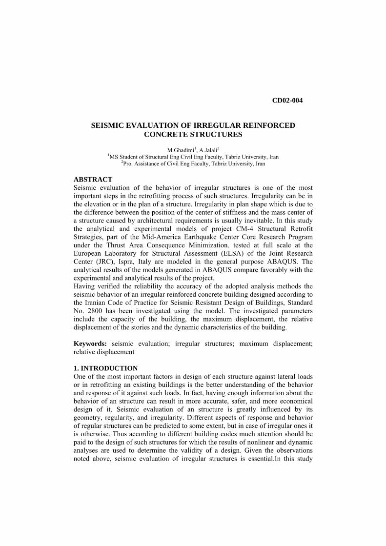
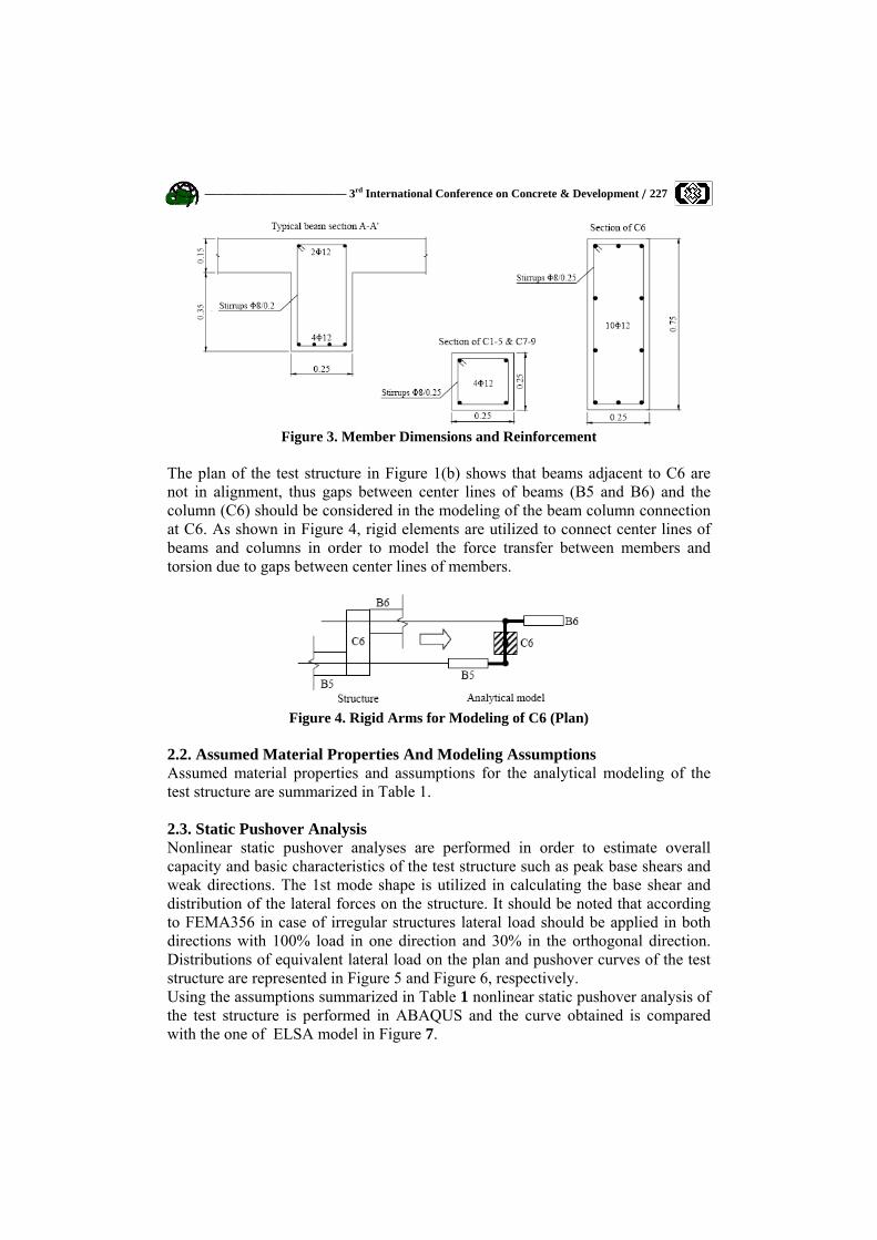
having verified the capability of an analytical model to simulate the nonlinear behavior of an irregular structure investigated experimentally, the provisions of the Iranian seismic code concerning design of irregular structures are also checked through the nonlinear static and dynamic analyses of an irregular RC building designed according to the mentioned provisions. 2. GENERAL DESCRIPTION OF THE TEST BUILDING 2.1. Geometry of the Test Model The structure is a simplification of an actual three-story building which is a representative of older construction in Southern Europe without earthquake design provisions. It is also similar to pre-seismic code construction in many other parts of the world. The test building has been designed for gravity loads alone, using the concrete design code applied in Greece between 1954 and 1995. Total dead loads and 30% of live loads are used for the gravity loads in the analysis. An overview of the test building and the plan of a typical repetitive floor are presented in Figure1. Infill walls and stairs are omitted in the model. Dimensions of the building are represented in Figure 2 and details of member dimensions and reinforcement are represented in Figure 3. Slabs are omitted in the analytical model and their contribution to beam stiffness and strength is reflected by effective width of the T-section. For the modeling of beams, a reinforced concrete T-section is utilized and the effective flange width is assumed to be the beam width plus 7% of the clear span of the beam on either side of the web (Fardis, 1994).
Figure 1. Overview of the Test Model and Plan
Figure 2. Geometry of the Test Model
–––––––––––––––––––––––– 3rd International Conference on Concrete & Development / 227
Figure 3. Member Dimensions and Reinforcement
The plan of the test structure in Figure 1(b) shows that beams adjacent to C6 are not in alignment, thus gaps between center lines of beams (B5 and B6) and the column (C6) should be considered in the modeling of the beam column connection at C6. As shown in Figure 4, rigid elements are utilized to connect center lines of beams and columns in order to model the force transfer between members and torsion due to gaps between center lines of members.
Figure 4. Rigid Arms for Modeling of C6 (Plan)
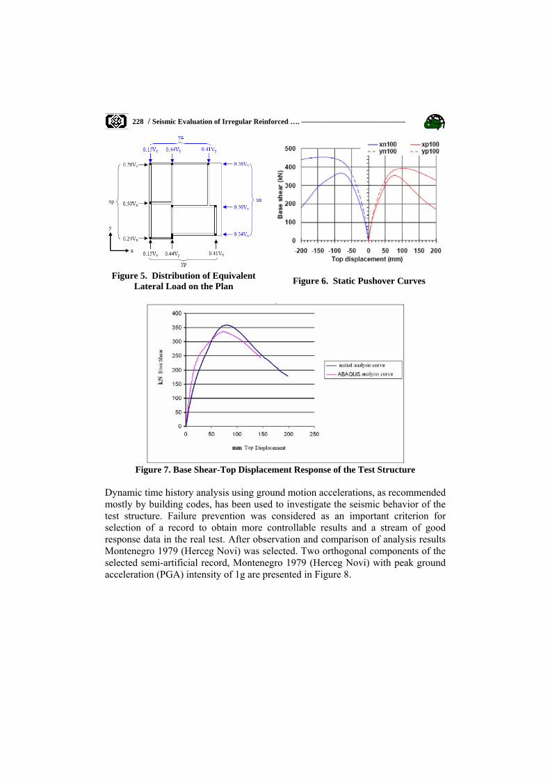
2.2. Assumed Material Properties And Modeling Assumptions Assumed material properties and assumptions for the analytical modeling of the test structure are summarized in Table 1. 2.3. Static Pushover Analysis Nonlinear static pushover analyses are performed in order to estimate overall capacity and basic characteristics of the test structure such as peak base shears and weak directions. The 1st mode shape is utilized in calculating the base shear and distribution of the lateral forces on the structure. It should be noted that according to FEMA356 in case of irregular structures lateral load should be applied in both directions with 100% load in one direction and 30% in the orthogonal direction. Distributions of equivalent lateral load on the plan and pushover curves of the test structure are represented in Figure 5 and Figure 6, respectively. Using the assumptions summarized in Table 1 nonlinear static pushover analysis of the test structure is performed in ABAQUS and the curve obtained is compared with the one of ELSA model in Figure 7.
228 / Seismic Evaluation of Irregular Reinforced …. ––––––––––––––––––––––––––––
Figure 5. Distribution of Equivalent
Lateral Load on the Plan Figure 6. Static Pushover Curves
Figure 7. Base Shear-Top Displacement Response of the Test Structure
Dynamic time history analysis using ground motion accelerations, as recommended mostly by building codes, has been used to investigate the seismic behavior of the test structure. Failure prevention was considered as an important criterion for selection of a record to obtain more controllable results and a stream of good response data in the real test. After observation and comparison of analysis results Montenegro 1979 (Herceg Novi) was selected. Two orthogonal components of the selected semi-artificial record, Montenegro 1979 (Herceg Novi) with peak ground acceleration (PGA) intensity of 1g are presented in Figure 8.

–––––––––––––––––––––––– 3rd International Conference on Concrete & Development / 229
Table 1: Assumed Material Properties and Assumptions for the Analytical Modeling Both of ELSA Model & Main Model
Assumptions Items in analytical modeling
Analytical Modeling in ABAQUS Analytical Modeling in ZeusNL
Yield strength fy=400 MPa
Post-yield stiffness to pre-yield stiffness ratio E2/E1=0.0056
Young's modulus E1=206000 MPa
(FeB32K from Italian market) Yield strength
fy=459 MPa (Φ 12) fy=377 MPa (Φ20)
Post-yield stiffness to pre-yield stiffness ratio
E2/E1=0.0032 (Φ12) E2/E1=0.0056 (Φ20)
Young's modulus E1=206000 MPa
Reinforcement steel
Compressive strength f'c=25 MPa
Confinement factor K=1.1, from Mander et al. (1988)
Compressive strength f'c=25 MPa
Confinement factor K=1.01, from Mander et al. (1988)
Concrete
Reinforcement steel Bilinear Elasto-plastic model
Concrete Model of Martinez-Rueda and
Elnashai (1997) based on Mander et al. (1988)
Reinforcement steel Bilinear Elasto-plastic model
Concrete Model of Martinez-Rueda and
Elnashai (1997) based on Mander et al. (1988)
Stress-strain relationship
Mat
eria
l
25000 kg/m3 25000 kg/m3 Self weight of RC member
DL+0.2LL DL+0.3LL Gravity loads
DL+0.2LL DL+0.3LL Seismic dead load for mass calculation
Distributed at beam column connections
Distributed at beam column connections
Mass distribution
Considered Considered P-delta effect
Rayleigh damping has been used No (Only hysteretic damping was considered.
Viscous damping
ABAQUS 6.3 ZeusNL (V.1.5) Analysis program
Distributed plasticity model Distributed plasticity model Element model
Yes Yes Centerline dimensions
No Yes (both at beam ends and column ends)
Rigid offset at beam column
connection
- Yes M-M-N interaction
-
Web width plus 7% of the clear span of
the beam on either side of the web
Effective flange width of T-
beams
Stru
ctur
al M
odel
ing

230 / Seismic Evaluation of Irregular Reinforced …. ––––––––––––––––––––––––––––
2.3. NONLINEAR DYNAMIC ANALYSIS
Figure 8. Acceleration Response History of Montenegro 1979 - Herceg Novi
After scaling down their PGA to 0.12g, 0.14g and 0.16g, they were applied to the building in eight different sets of directions as shown in Figure 9. Each combination of directions is defined as D1-D8, respectively.
Figure 9. Combinations of Directions to Apply Ground Motions
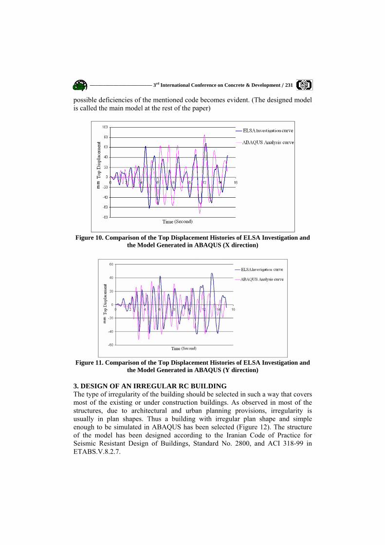
Montenegro 1979 (Herceg Novi) record at 0.15g PGA in the direction D1 had been selected as an appropriate earthquake scenario for the test. Using the same record at 0.15g PGA in the direction D1 nonlinear dynamic analysis of the test structure is performed in ABAQUS and the curve obtained is compared with the one of ELSA model in Figure 10 and Figure 11. Which verifies the accuracy of the adopted analysis methods. Having verified the reliability of the analytical model generated and analyzed in ABAQUS, the seismic behavior of an irregular reinforced concrete building designed according to the Iranian Code of Practice for Seismic Resistant Design of Buildings, Standard No. 2800, has been investigated using the model, so that the
–––––––––––––––––––––––– 3rd International Conference on Concrete & Development / 231
possible deficiencies of the mentioned code becomes evident. (The designed model is called the main model at the rest of the paper)
Figure 10. Comparison of the Top Displacement Histories of ELSA Investigation and
the Model Generated in ABAQUS (X direction)
Figure 11. Comparison of the Top Displacement Histories of ELSA Investigation and
the Model Generated in ABAQUS (Y direction) 3. DESIGN OF AN IRREGULAR RC BUILDING The type of irregularity of the building should be selected in such a way that covers most of the existing or under construction buildings. As observed in most of the structures, due to architectural and urban planning provisions, irregularity is usually in plan shapes. Thus a building with irregular plan shape and simple enough to be simulated in ABAQUS has been selected (Figure 12). The structure of the model has been designed according to the Iranian Code of Practice for Seismic Resistant Design of Buildings, Standard No. 2800, and ACI 318-99 in ETABS.V.8.2.7.

232 / Seismic Evaluation of Irregular Reinforced …. ––––––––––––––––––––––––––––
a) 3D View of the Model b) Plan of the Model
Figure 12. Overview of the Model and Plan 3.1. Simulation of the Main Model in Abaqus Assumed material properties and assumptions for the analytical modeling of the main model are summarized in Table 2. A model proposed by Mander et al. (1988) is adopted for stress-strain relationships of confined concrete and evaluating the confining effect K (Figure 13).
Figure 13. Stress-Strain Relationship of Confined Concrete
3.2. Modal Analysis In order to understand the overall response of the structure, periods and mode shapes are obtained using 3D modeling in ABAQUS. Three main mode shapes and corresponding frequencies are presented in Figure 14.

–––––––––––––––––––––––– 3rd International Conference on Concrete & Development / 233
Figure 14. Three Main Mode Shapes
3.3. Nonlinear Static Analysis As mentioned in previous sections nonlinear static pushover analyses are performed in order to estimate overall capacity and basic characteristics of a structure such as peak base shears and weak directions, and according to FEMA356 in case of irregular structures lateral load should be applied in both directions with 100% load in one direction and 30% in the orthogonal direction. Thus in this phase of the study the model has been subjected to lateral load first in one direction(X) and then in both directions (100% load in one direction and 30% in the orthogonal direction) (Figure 15), and the results are presented in Figure 16.
Figure 15. Distribution of Equivalent
Lateral Load on the Plan Figure 16. Base Shear Versus top
Displacement of the Model 3.4. Nonlinear Dynamic Analysis Time-history dynamic analysis using ground motion accelerograms has been recommended mostly by building codes. According to the Iranian Code of Practice for Seismic Resistant Design of Buildings, Standard No. 2800 ground motion effects can be applied either by acceleration spectrum or time history. In this study, according to the code, three scaled accelerograms have been used. (Table 3 and

234 / Seismic Evaluation of Irregular Reinforced …. ––––––––––––––––––––––––––––
Table 4). The results of the nonlinear dynamic analysis subjected to Montenegro 1979 (semi artificial) ground motion, are indicated in Figure 17, Figure 18, and Figure 19.
Table 3 Earthquake PGA (x) PGA (y)
Montenegro1979 ( semi artificial) 1g 1g Tabas 0.878g 0.933g
El-Centro 0.214g 0.312g
Table 4
Earthquake Items Max PGA Scale factor
Max PGA after Scaled
PGA (X) 1g 0.35 0.35g Montenegro1979 ( semi artificial) PGA (Y) 1g 0.35 0.35g
PGA (X) 0.878g 0.52 0.457g Tabas PGA (Y) 0.933g 0.552 0.5151g PGA (X) 0.214g 1.801 0.3868g El-Centro PGA (Y) 0.312g 1.249 0.435g
4. CONCLUSIONS Since the building has been designed according to the Iranian Standard No. 2800, its provisions and the observations of similar building codes can be used to evaluate the results of the analyses
Figure 17. Base Shear-Time Response of the Model in Both Directions (X, Y)
Figure 18. Top Displacement-Time Response of Column C5 in Both Directions (X, Y)

–––––––––––––––––––––––– 3rd International Conference on Concrete & Development / 235
Figure 19. Drift -Time Response of C5 at 3rd Floor in Both Directions (X, Y)
Figure 20. Torque at the Top of Column C5, Subjected to El-Centro Ground Motion.
4.1. The Conclusions of the Nonlinear Static Analysis 1. according to the capacity curve obtained through static pushover analysis the maximum inelastic displacement of the structures with a period of about 0.7 second, 2.5%, determined by FEME and Iranian seismic design code, is observed in the main model and softening of the model begins at the displacement of about 40cm. 2. The displacement of about 40cm is observed in the obtained capacity curve. In this region the amount of the force does not change considerably, and the structure withstands the applied load at the large displacement caused by yield and failure of the longitudinal reinforcement of the members until the collapse of the building. Comparing the results with the results of the model tested by ELSA, it can be concluded that the structure designed according to the Iranian seismic code is much more ductile and can absorb much more energy. 3. As mentioned before, according to the provisions of seismic codes, irregular structures should be loaded in both directions which, as observed in the ELSA model, accounts for the reduction in the ductility of the structure (Figure). While the results obtained by the analysis of the main model (designed by the authors) prove the fact that in the provisions of the Iranian seismic code this phenomenon has been taken into account and no reduction in the ductility of the model due to bidirectional loading has been observed. 4.2. The Conclusions of the Nonlinear Dynamic Analysis 1. The relative lateral displacement of stories of the structure subjected to El Centro
236 / Seismic Evaluation of Irregular Reinforced …. ––––––––––––––––––––––––––––
and Tabas accelerograms has not exceeded the maximum amount defined in the Iranian seismic code, except for the lateral displacement of the third story resulted from Montenegro accelerogram which was about 4cm and 1.33% of the allowable relative displacement in the code. 2. The amount of the torsion is considerable and as illustrated in Figure 14 the torsional mode shape is the third mode shape with a period of 0.536 sec which is about the period of the first mode shape (0.659 sec). as was expected, column C5 is subjected to the maximum amount of torsion. 4.3. Final Conclusion Considering all the results stated above it can be concluded that the provisions of the Iranian Code of Practice for Seismic Resistant Design of Buildings, Standard No. 2800 are appropriate for seismic design of the irregular reinforced concrete structures having 5 stories or being 18 meters in height. REFERENCE 1. Shah, H, C. Zsutty, T.C and Padilla, L. “The Purpose and Effect of
Earthquake” Internal Study Report No.1, the John A.Blume Earthquake Engineering Center, Stanford Univ, 1977.
2. Reitherman, R.K... “Frank Lloyd Wright’s Imperial Hotel: A Seismic Re-evaluation”. Proc. Seventh World Conference on Earthquake Engineering, Istanbul 1980.
3. Dowrick, D.J., Earthquake Resistant Design, John Wiley & Sons, London, 1977. 4. Naito, T., “Earquake-Proof Construction,” Bull. Seism. Soc. Am.17 .No.2,
June 1977. 5. Degenkolb, H.,”Seismic Design: Structural Concept,” Summer Seismic
Institute for Architectural Faculty, AIA Research Corp., Washington, 1977. 6. Dewell, H.and Willis, B., “Earthquake Damage to Building,” Bull. Seism. Soc.
Am.15 .No.4, Dec 1925. 7. Iranian Code of Practice for Seismic Resistant Design of Buildings, Standard
No. 2800. 8. S.-H. Jeong & A. S. Elnashai.,” Analytical Assessment of an Irregular RC
Frame for Full-Scale 3D PsD Testing-Part I”. Journal of Earthquake Engineering, Vol. 9, No. 1 (2005) 95-128-Imperial College Press.
9. S.-H. Jeong & A. S. Elnashai.,” Analytical Assessment of an Irregular RC Frame for Full-Scale 3D PsD Testing-Part II”. Journal of Earthquake Engineering, Vol. 9, No. 2 (2005) 265.
10. Mander, J. B., Priestley, M. J. N. and Park, R. [1988] “Theoretical stress-strain model for Confined concrete,” ASCE Journal of Structural Engineering 114(8), 1804-1826.
11. ABAQUS USER MANUAL Ver. 6.5.1 12. Shah, S.P., Swartz, S.E., and Ouyang, C., Fracture Mechanics of Concrete
Applications of Fracture Mechanics to Concrete, Rock, and Other Quasi-Brittle Materials, John Wiley & Sons, 1995.


![Seismic Design of Vertically Irregular Reinforced Concrete Structures[1]](https://img.dokumen.tips/doc/110x75/55cf8e92550346703b938335/seismic-design-of-vertically-irregular-reinforced-concrete-structures1.jpg)