Embed Size (px)
Citation preview

Florida International University 05/09/2012Finish Hardware SpecificationsSection 08 71 00
DOOR HARDWARE Section 08 71 00Page 1 of 29
SECTION 08 71 00FINISH HARDWARE
PART 1 GENERAL
1.01 SECTION INCLUDES
A. Finish hardware items required for swinging doors indicated on schedules and/or shown ondrawings including hinges, lock or latch sets, dead locks, cylinders, bolts, exit devices, push/pullunits, closers and miscellaneous door and access control devices, protection plates, and othermiscellaneous hardware.
1.02. RELATED SECTIONS
1. Section 06 40 00 - Architectural Woodwork
2. Section 08 11 00 - Metal Doors and Frames
3. Section 08 14 00 - Wood Doors
4. Section 08 41 00 – Entrances and Storefronts
5. Division 28 00 00 – Electronic Safety and Security
6. Section 28 05 13 -Conductors and Cables for Electronic Safety and Security
7. Section 28 13 00- Access Control
1.03 REFERENCES
A. American National Standards Institute (ANSI):1. ANSI A156 Series2. ANSI A115W Wood Door Hardware Standards; Hardware Preparation3. ANSI A115 Specifications for Steel Door and Frame Preparation for Hardware4. ANSI A117.1 Accessible and Usable Buildings and Facilities5. ANSI A250.6 Hardware on Steel Doors (Reinforcement - Applications)
B. Door and Hardware Institute (DHI)1. Sequence and format for hardware schedule, keying system, and nomenclature.2. Recommended locations for Architectural Hardware for Standard Steel Doors and
Frames – 19903. Basic Architectural Hardware – 1985
C. Builders Hardware Manufacturing Association (BHMA)1. BHMA Product Standards, latest edition2. ANSI/BHMA A156.18 – Standard for materials and Finishes
D. National Fire Protection Association (NFPA)1. NFPA 80 Fire Doors and Windows2. NFPA 101 Life Safety Codes
E. Americans with Disabilities Act Accessibility Guidelines (ADAAG)
Florida International University 05/09/2012Finish Hardware SpecificationsSection 08 71 00
DOOR HARDWARE Section 08 71 00Page 2 of 29
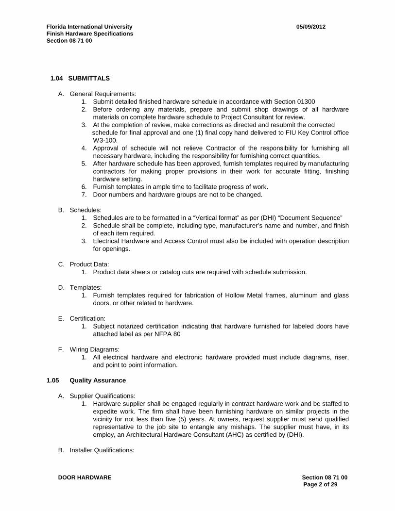
1.04 SUBMITTALS
A. General Requirements:1. Submit detailed finished hardware schedule in accordance with Section 013002. Before ordering any materials, prepare and submit shop drawings of all hardware
materials on complete hardware schedule to Project Consultant for review.3. At the completion of review, make corrections as directed and resubmit the corrected
schedule for final approval and one (1) final copy hand delivered to FIU Key Control officeW3-100.
4. Approval of schedule will not relieve Contractor of the responsibility for furnishing allnecessary hardware, including the responsibility for furnishing correct quantities.
5. After hardware schedule has been approved, furnish templates required by manufacturingcontractors for making proper provisions in their work for accurate fitting, finishinghardware setting.
6. Furnish templates in ample time to facilitate progress of work.7. Door numbers and hardware groups are not to be changed.
B. Schedules:1. Schedules are to be formatted in a “Vertical format” as per (DHI) “Document Sequence”2. Schedule shall be complete, including type, manufacturer’s name and number, and finish
of each item required.3. Electrical Hardware and Access Control must also be included with operation description
for openings.
C. Product Data:1. Product data sheets or catalog cuts are required with schedule submission.
D. Templates:1. Furnish templates required for fabrication of Hollow Metal frames, aluminum and glass
doors, or other related to hardware.
E. Certification:1. Subject notarized certification indicating that hardware furnished for labeled doors have
attached label as per NFPA 80
F. Wiring Diagrams:1. All electrical hardware and electronic hardware provided must include diagrams, riser,
and point to point information.
1.05 Quality Assurance
A. Supplier Qualifications:1. Hardware supplier shall be engaged regularly in contract hardware work and be staffed to
expedite work. The firm shall have been furnishing hardware on similar projects in thevicinity for not less than five (5) years. At owners, request supplier must send qualifiedrepresentative to the job site to entangle any mishaps. The supplier must have, in itsemploy, an Architectural Hardware Consultant (AHC) as certified by (DHI).
B. Installer Qualifications:

Florida International University 05/09/2012Finish Hardware SpecificationsSection 08 71 00
DOOR HARDWARE Section 08 71 00Page 3 of 29
1. Installers must have a minimum (5) five years experience of installing commercial gradehardware. Prior installation installer must attend a pre-installation class with hardwaremanufactures.
C. Make occasional inspections and verify that items are properly used, installed, and in correctlocation. Report improper application of hardware to Owner.
D. Ensure the provision, proper coordination and functioning of finish hardware required for allopenings, whether or not hereinafter listed in the detailed schedule, including proper type of strikeplates, length of spindle, hand, backset and bevel of locks, hand and degree opening for closers,length of kick plates, length of rods and flush bolts, type of door stop and other functions ormechanism to meet the requirements of the project.
E. Once building has been acquired by the owner, and has operated for (6) six months. Installer mustreturn to adjust any or all hardware for proper operation.
1.06 DELIVERY, STORAGE, AND HANDLING
A. Send duplicate lists of hardware in each shipment to the contractor. Ensure original listaccompanies shipment. Hardware Vendor: pay shipping and delivery charges.
B. Coordinate delivery of hardware to respective shops of subcontractors as required. Ensure timelydelivery of hardware components.
C. Hardware: sorted and delivered to jobsite marked to correspond with item numbers of vendor'sapproved schedule and be specific as to exact opening and other locations for which items arepackaged. Each door opening: receive separate item number of hardware schedule.
D. Check all shipments to insure proper accessories and templates.
E. Deliver hardware only after detailed schedule, and samples have been approved.
F. Provide secure lock-up for hardware delivered to the project. Control handling and installation ofhardware items which are not immediately replaceable so that the completion of the work will notbe delayed by hardware losses.
G. Protection:1. Leave protective coatings when at all possible.
1.07 WARRANTY
A. All hardware and installation must provide warranty against defects and workmanship; refer toDivision 1 for proper clarifications.
B. Mechanical Locks and Electronic Access Locks: Warranted in writing by the manufacturer againstfailure due to defective materials and workmanship, for a period of five (5) years commencingfrom the Date of installation
C. Other Electronic Hardware (Power supplies, EL/RX/LX switches, etc.): Warranted for one (1) yearfrom Date of Purchase.
D. Overhead Door Closers: Warranted in writing by the manufacturer against failure due todefective materials and workmanship, for a period of ten (10) years commencing on the Date of

Florida International University 05/09/2012Finish Hardware SpecificationsSection 08 71 00
DOOR HARDWARE Section 08 71 00Page 4 of 29
Final Completion and Acceptance, and in the event of failure, the manufacturer is to promptlyrepair or replace the defective with no additional cost to the Owner.
PART 2 PRODUCTS
2.01 MANUFACTURER’S
A. Manufacturer’s Acceptable
HAGERMcKINNEYBOMMERSTANLEYFALCON LOCK CO.VON-DUPRINSCHLAGE ELECTRONICSLCNGYLNN JOHNSONH.B. IVES CO.PEMKONATIONAL GUARDREESEZERO
2.01 MATERIALS AND FABRICATION
A. Material: Use manufacture’s standard metal alloy as specified and by ANSI A156 seriesstandards. Stainless Steel material and finish 630 (US32D) when provided by manufacture forsaid products listed; 626 (US26D) may also be an alternative.
B. Fasteners: Provide hardware manufacture to conform to published templates, generally preparedfor machine screw installation. Do not provide hardware, which has been prepared for self-tappingsheet metal screws, except, as specifically indicated.
C. Furnish screws for installation, with each hardware item. Provide Phillips flat-head screws exceptas otherwise indicated. Finish exposed (exposed under any condition) screws to match hardwarefinish or, if exposed in surfaces of other work to match finish of such other work, including“prepare for paint” in surfaces to receive painted finish.
D. Provide thru-bolts (sex bolts) for high traffic and heavy-duty use areas for doors not prepared formachine screws (staving, extra plating) for closers, panic and fire exit devices, stops and holders.
E. Tools and Maintenance Instructions for Maintenance: Furnish a complete set of specialized toolsand maintenance instructions as needed for owner’s continued adjustments, maintenance, andremoval and replacement of finish hardware. Return all unused material to owner, (Key Control).
2.02 HINGES AND BUTTS
A. Domestic manufacture equal to Hager, Ives, Stanley, McKinney, and Bommer.

Florida International University 05/09/2012Finish Hardware SpecificationsSection 08 71 00
DOOR HARDWARE Section 08 71 00Page 5 of 29
B. Quantity: Use 1.5 pair three (3) hinges for each door leaf up to and including 7'-6" in height doorsover 7’-6’ add an additional 0.5 pair one (1) hinge and 0.5 pair one (1) hinge for each door leaf 40inches to 48 inches in width.
C. Ensure all doors equipped with closers are furnished with ball bearing (BB) hinges.
D. Size, Type and Finish: Provide the following unless otherwise noted in the hardware group.1. Exterior Doors with Closers: BB1199 4-1/2 inches x 4-1/2 inches with Non Removable Pins
(NRP) BHMA 630 satin stainless steel finish.2. Interior Doors: BB1279- 4-1/2 inches x 4-1/2 inches BHMA 652 steel satin chromium finish.
3. Interior Doors with Closers: BB1279 4-1/2 inches x 4-1/2 inches BHMA 652 steel satinChromium finish for door leaf up to and including 36 inches wide.
2.03 LOCKS AND LATCHSETS
A. All Locksets: Falcon Lock Company. No Substitutions Allowed.1. All locks to be “MA” series, SN design. and or D111 deadbolt.2. Provide Falcon Restricted “M” or “Q” keyway for all cylinders. “T” keyway for Biscayne
Campus.
B. Lock Trim, Latch Face and Strike Finish: BHMA 626 stainless steel chromium plated satin finish.
C. Functions as designated in hardware sets.
D. Provide all mechanical, electrical, custodial storage and any area deemed to be hazardous to thevisually impaired, with door levers having tactile warning; manufacturers standard eight (8),applied to the exterior lever.
E. Provide plastic strike boxes at all interior and exterior frames, and all double doors inactive leaf.
2.04 KEYS AND KEYING
A. All cylinders to be shipped “0” bitted. No keys or cylinders will be delivered to or any authorizationletters issued for receiving shipments other then to Owner, FIU.
B. All locks are delivered less cylinder to contractor. Contractor to provide temporary constructioncylinders.
C. Ensure all locks and cylinders are Falcon Lock standard cylinder 7-pin “M” or “Q” RestrictedKeyway. “T” Restricted keyway for Biscayne Campus.
D. Ensure that at no time, the General Contractor or sub-contractor has possession of thepermanent keys.
E. Upon completion of the Project, the Owner will Install all cylinders and collect all construction keysand temporary cylinders, construction cylinders are to be provided and installed by contractor.
F. Provide three (3) change keys per lock.

Florida International University 05/09/2012Finish Hardware SpecificationsSection 08 71 00
DOOR HARDWARE Section 08 71 00Page 6 of 29
2.05 CLOSING DEVICES
A. All hydraulic door closers (including those having electric releases) furnished by one (1)Manufacturer and guaranteed for ten (10) years.
B. All Closers:1. LCN 4041XP EDA Series having non-ferrous covers, forged steel arms separate valves for
Adjusting backcheck, closing and latching cycles and adjustable spring to provide sizesOne (1) through six (6).
2. Provide parallel arm mount on all doors opening into corridors or other public spaces andmounted to permit 180 degrees door swing wherever wall conditions permit.
3. Provide with non-hold open arms unless otherwise indicated.
C. Door Closer Cylinders:1. Only high strength cast iron construction to provide low wear operating capabilities of internal
parts throughout the life of the installation.2. Tested to ANSI/BHMA A 156.4 test requirements by a BHMA certified testing laboratory.3. Provide a written certification showing successful completion of a minimum of 10,000,000
cycles.
D. Door Closers:1. Utilize temperature stable fluid capable of withstanding temperature ranges of 120 degrees
Fahrenheit to minus 30 degrees Fahrenheit, without requiring seasonal adjustment of closerspeed to properly close the door.
2. Closers for Fire-Rated Doors: Provide with temperature stabilizing fluid that complies with thestandards UBC 7-2 (1997) and UL10C.
3. Incorporate tamper resistant non-critical screw valves of V-slot design to reduce possibleclogging from particles within the closer.
4. Have separate and independent screw valve adjustments for latch speed, general speed, andhydraulic back check.
5. Properly locate so as to effectively slow the swing of the door at a minimum of 10 degrees inadvance of the dead stop location to protect the doorframe and hardware from damage.
6. Pressure Relief Valves (PRV) are not acceptable.
E. Ensure all components are powder coated including the cylinder and have passed a 100 hour saltspray test.
F. Provide all accessories necessary for proper operation of doors including drop plates. ProvideSpring Cush arms where auxiliary stops not feasible.
G. Door closers shall be thru-bolted
2.06 PANIC AND FIRE EXIT DEVICES
A. Devices:1. Von Duprin 98/99 and 33A/35A Series.2. Ensure devices are listed under “Panic Hardware” in accident equipment list of Underwriters
Laboratories.3. All labeled doors with “Fire Exit Hardware” must have labels attached and be under strict
provisions of Underwriters Laboratories.

Florida International University 05/09/2012Finish Hardware SpecificationsSection 08 71 00
DOOR HARDWARE Section 08 71 00Page 7 of 29
B. Exit Devices: Tested to ANSI/BHMA A 156.3 test requirements by a BHMA certified testinglaboratory. Provide a written certification showing successful completion of a minimum of1,000,000 cycles.
C. Surface Strikes: Roller type and come complete with a plate underneath to prevent movement.Provide with a dead-latching feature to prevent latch bolt tampering.
D. Provide Von Duprin 98L/99L,33A-L/35A-L, key retracted latch bolt and 996L-R-17 or 360L-17 trimwith number 425 sex bolts, as noted in the hardware groups.
E. Exit Devices or Panic Devices on an entry to access a building equipped with AD exterior trim andan RX-LC switch in device for Access Control System also provide controllers, readers, powertransfers, interface board and power supply for each and every door except for exit only doors;only Von Duprin is to be used.
2.07 PUSH, PULL, KICK, MOP, AND ARMOR PLATES
A. Push Plates: Ives 8 inches x 16 inches, US32D Finish.
B. Pull Plates: Ives 8305-0 4 inches x 16 inches, US32D Finish.
C. Kickplates: Provide on push side of doors with closers, but not on closer/holder doors unlessscheduled otherwise. 10 inches high, 0.050 thick, bevelled on all exposed edges and sized perbelow:1. Single Doors: 2 inches LDW (less door width).2. Pairs of Doors: 1 inches LDW (less door width).
D. Mop plates: 6 inches high, 0.050 thick beveled on all exposed edges and sized per below:1. Single Doors: 2 inches LDW (less door width).2. Pairs of Doors: 1 inches LDW (less door width).
E. Armourplates: 34 inches in height, 0.050 thick, bevelled on all exposed edges and sized perbelow:1. Single Doors: 2 inches LDW (less door width).2. Pairs of Doors: 1 inches LDW (less door width).
E. Finishes: Stainless steel, BHMA 630.
F. Provide stainless steel screws.
G. Coordinate with ADA and other accessibility code requirements.
2.08 EXTENSION FLUSH BOLTS AND AUTOMATIC FLUSH BOLTS
A. Provide extension flush bolts as manufactured by H.B. Ives, Model FB458, UL Listed, 12 inches.US26D finish. Doors over 7’-6” provide 18 inches.
C. Provide automatic flush bolts as manufactured by H.B. Ives, Model FB30 or FB40, UL Listed,US32D finish use appropriate model for door type and undercut,
D. Provide H.B. Ives, Model DP1, dust proof strike and DP2 plate with screws and lead shields.

Florida International University 05/09/2012Finish Hardware SpecificationsSection 08 71 00
DOOR HARDWARE Section 08 71 00Page 8 of 29
2.09 WALL AND FLOOR DOOR STOPS
A. Provide H.B. Ives, WS406 wall stop in US32D Finish, where doors in an open position parallel amasonry wall.
B. Provide H.B. Ives, WS407 wall stop in US32D Finish, where doors in an open position parallel ametal stud board wall.
D. Provide H.B. Ives, 443,444,447,448 B26D for heavy duty door stops when wall exceeds morethan 8 inches form a 90-110 degree open door.
2.10 WEATHERSTRIPS, SWEEPS, DRIP CAPS, AND THRESHOLDS
A. Rigid Jamb and Head Weatherstrip: Aluminum mill finish, neoprene bulb insert, stainless steelscrews. UL10C Listed. Manufacturers: Pemko 290A, Reese 815A, National Guard 160A, ZeroInternational 328A.
B. Door Bottom Sweeps: Clear anodized aluminum finish, neoprene insert, stainless steel screws.Manufacturers: Pemko 315CN, National Guard 200NA, Reese 323A, Zero International 39A.
C. Door Top Rain Drip:1. Provide only when doors are exposed to rain.2. Clear anodized aluminum finish, neoprene insert, stainless steel screws.3. Manufacturers: Pemko 346C, National Guard 16A, Reese 201A, Zero International.
D. Saddle Threshold and Threshold Stop Strip (Two-Piece Assembly): Aluminum threshold with millfinish, neoprene bulb insert stainless steel screws. Manufacturers: Pemko 271A threshold and290A threshold stop, National Guard 513 threshold and 700E stop, Reese 5405A threshold and854A threshold stop, Zero International 544A.
E. Saddle Threshold (Interior Use): Aluminum mill finish, stainless steel screws. Manufacturers:Pemko 151A, National Guard 413, Reese 263A, Zero International 544A.
F. Carpet/Special Purpose Threshold: Aluminum mill finish. Manufacturers: Pemko 2364A,National Guard 404, Reese S562A, Zero International 1684A.
G. Latching Panic Exit Saddles: Aluminum mill finish. Manufacturers: Pemko 2005A, NationalGuard 896A. Reese S250, Zero 65.
2.11 SOUNDPROOFING
A. Automatic Door Bottoms: Surface mounted, clear anodized aluminum, stainless steel screws.Manufacturers: Zero International 369A.with Z49 Mounting for cleaning
B. Head and Jamb Sound Seals: Clear anodized aluminum, stainless steel screws. Manufacturers:Zero International 328AA.
2.12 ACCESSORIES
Florida International University 05/09/2012Finish Hardware SpecificationsSection 08 71 00
DOOR HARDWARE Section 08 71 00Page 9 of 29
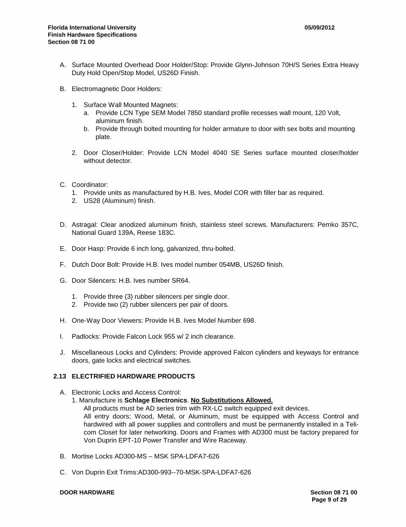
A. Surface Mounted Overhead Door Holder/Stop: Provide Glynn-Johnson 70H/S Series Extra HeavyDuty Hold Open/Stop Model, US26D Finish.
B. Electromagnetic Door Holders:
1. Surface Wall Mounted Magnets:a. Provide LCN Type SEM Model 7850 standard profile recesses wall mount, 120 Volt,
aluminum finish.b. Provide through bolted mounting for holder armature to door with sex bolts and mounting
plate.
2. Door Closer/Holder: Provide LCN Model 4040 SE Series surface mounted closer/holderwithout detector.
C. Coordinator:1. Provide units as manufactured by H.B. Ives, Model COR with filler bar as required.2. US28 (Aluminum) finish.
D. Astragal: Clear anodized aluminum finish, stainless steel screws. Manufacturers: Pemko 357C,National Guard 139A, Reese 183C.
E. Door Hasp: Provide 6 inch long, galvanized, thru-bolted.
F. Dutch Door Bolt: Provide H.B. Ives model number 054MB, US26D finish.
G. Door Silencers: H.B. Ives number SR64.
1. Provide three (3) rubber silencers per single door.2. Provide two (2) rubber silencers per pair of doors.
H. One-Way Door Viewers: Provide H.B. Ives Model Number 698.
I. Padlocks: Provide Falcon Lock 955 w/ 2 inch clearance.
J. Miscellaneous Locks and Cylinders: Provide approved Falcon cylinders and keyways for entrancedoors, gate locks and electrical switches.
2.13 ELECTRIFIED HARDWARE PRODUCTS
A. Electronic Locks and Access Control:1. Manufacture is Schlage Electronics. No Substitutions Allowed.
All products must be AD series trim with RX-LC switch equipped exit devices.All entry doors; Wood, Metal, or Aluminum, must be equipped with Access Control andhardwired with all power supplies and controllers and must be permanently installed in a Teli-com Closet for later networking. Doors and Frames with AD300 must be factory prepared forVon Duprin EPT-10 Power Transfer and Wire Raceway.
B. Mortise Locks AD300-MS – MSK SPA-LDFA7-626
C. Von Duprin Exit Trims:AD300-993--70-MSK-SPA-LDFA7-626
Florida International University 05/09/2012Finish Hardware SpecificationsSection 08 71 00
DOOR HARDWARE Section 08 71 00Page 10 of 29
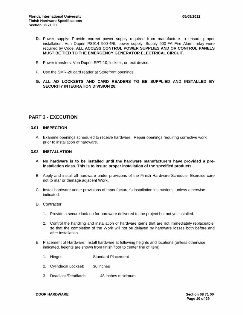
D. Power supply: Provide correct power supply required from manufacture to ensure properinstallation. Von Duprin PS914 900-4RL power supply. Supply 900-FA Fire Alarm relay wererequired by Code. ALL ACCESS CONTROL POWER SUPPLIES AND OR CONTROL PANELSMUST BE TIED TO THE EMERGENCY GENERATOR ELECTRICAL CIRCUIT.
E. Power transfers: Von Duprin EPT-10, lockset, or, exit device.
F. Use the SMR-20 card reader at Storefront openings
G. ALL AD LOCKSETS AND CARD READERS TO BE SUPPLIED AND INSTALLED BYSECURITY INTEGRATION DIVISION 28.
PART 3 - EXECUTION
3.01 INSPECTION
A. Examine openings scheduled to receive hardware. Repair openings requiring corrective workprior to installation of hardware.
3.02 INSTALLATION
A. No hardware is to be installed until the hardware manufacturers have provided a pre-installation class. This is to insure proper installation of the specified products.
B. Apply and install all hardware under provisions of the Finish Hardware Schedule. Exercise carenot to mar or damage adjacent Work.
C. Install hardware under provisions of manufacturer's installation instructions; unless otherwiseindicated.
D. Contractor:
1. Provide a secure lock-up for hardware delivered to the project but not yet installed.
2. Control the handling and installation of hardware items that are not immediately replaceable,so that the completion of the Work will not be delayed by hardware losses both before andafter installation.
E. Placement of Hardware: Install hardware at following heights and locations (unless otherwiseindicated, heights are shown from finish floor to center line of item)
1. Hinges: Standard Placement
2. Cylindrical Lockset: 36 inches
3. Deadlock/Deadlatch: 48 inches maximum
Florida International University 05/09/2012Finish Hardware SpecificationsSection 08 71 00
DOOR HARDWARE Section 08 71 00Page 11 of 29
4. Push Plate: 48 inches
5. Pull Plate: 42 inches
6. Panic Bar: 36 inches
7. Kick Plate: 1/4 inch from door bottom
C. Closer: Per manufacturer's template to give maximum degree of opening. Mount closers onroom side of door. All door closers shall be thru-bolted
D. Stops and Holders:
1. Wall: On block wall or stud wall where knob or pull hits.
2. Overhead Door Holder: Per template.
3. Door Holder: 2 inches from lead edge of door.
3.03 ADJUSTING AND CLEANING
A. Contractor: Adjust all hardware under strict provisions of manufacturers’ instructions. Prior toturning project over to Owner, clean and make final adjustments to the finish hardware. Oncebuilding has operated for six (6) months, contractor must return for adjustments on finishedhardware.
3.04 PROTECTION
A. Contractor: Protect all hardware, as it is stored on construction site in a covered and dry place.Protect exposed hardware installed on doors during the construction phase. Leave protectivecoating when possible and remove at owner’s request.
3.05 DESCRIPTION OF HARDWARE GROUP NUMBERS
A. The following schedule is to be used as a general guide. Special or unusual conditions notcovered will have hardware of similar type and quality to meet job conditions. Supply hardware tomeet project requirements and produce complete project.
Manufacturer Index:
FAL = Falcon LockIVE = H.B. IvesLCN = LCN ClosersSCE = Schlage ElectronicsSTC = StanleyTRI = TrimcoVON = Von DuprinZER = Zero International
Florida International University 05/09/2012Finish Hardware SpecificationsSection 08 71 00
DOOR HARDWARE Section 08 71 00Page 12 of 29
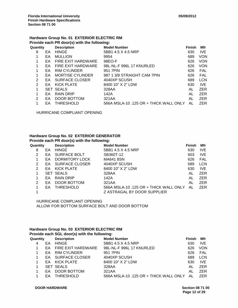
Hardware Group No. 01 EXTERIOR ELECTRIC RMProvide each PR door(s) with the following:Quantity Description Model Number Finish Mfr
8 EA HINGE 5BB1 4.5 X 4.5 NRP 630 IVE1 EA MULLION 9954 689 VON1 EA FIRE EXIT HARDWARE 98EO-F 626 VON1 EA FIRE EXIT HARDWARE 98L-NL-F 996L 17 KNURLED 626 VON1 EA RIM CYLINDER 951 7PIN 626 FAL1 EA MORTISE CYLINDER 987 1 3/8 STRAIGHT CAM 7PIN 626 FAL2 EA SURFACE CLOSER 4040XP SCUSH 689 LCN2 EA KICK PLATE 8400 10" X 2" LDW 630 IVE1 SET SEALS 328AA AL ZER1 EA RAIN DRIP 142A AL ZER2 EA DOOR BOTTOM 321AA AL ZER1 EA THRESHOLD 566A MSLA-10 .125 OR + THICK WALL ONLY AL ZER
HURRICANE COMPLIANT OPENING
Hardware Group No. 02 EXTERIOR GENERATORProvide each PR door(s) with the following:Quantity Description Model Number Finish Mfr
8 EA HINGE 5BB1 4.5 X 4.5 NRP 630 IVE2 EA SURFACE BOLT SB360T-12 603 IVE1 EA DORMITORY LOCK MA641 8SN 626 FAL2 EA SURFACE CLOSER 4040XP SCUSH 689 LCN2 EA KICK PLATE 8400 10" X 2" LDW 630 IVE1 SET SEALS 328AA AL ZER1 EA RAIN DRIP 142A AL ZER2 EA DOOR BOTTOM 321AA AL ZER1 EA THRESHOLD 566A MSLA-10 .125 OR + THICK WALL ONLY AL ZER1 Z ASTRAGAL BY DOOR SUPPLIER
HURRICANE COMPLIANT OPENINGALLOW FOR BOTTOM SURFACE BOLT AND DOOR BOTTOM
Hardware Group No. 03 EXTERIOR ELECTRIC RMProvide each SGL door(s) with the following:Quantity Description Model Number Finish Mfr
4 EA HINGE 5BB1 4.5 X 4.5 NRP 630 IVE1 EA FIRE EXIT HARDWARE 98L-NL-F 996L 17 KNURLED 626 VON1 EA RIM CYLINDER 951 7PIN 626 FAL1 EA SURFACE CLOSER 4040XP SCUSH 689 LCN1 EA KICK PLATE 8400 10" X 2" LDW 630 IVE1 SET SEALS 328AA AL ZER1 EA DOOR BOTTOM 321AA AL ZER1 EA THRESHOLD 566A MSLA-10 .125 OR + THICK WALL ONLY AL ZER

Florida International University 05/09/2012Finish Hardware SpecificationsSection 08 71 00
DOOR HARDWARE Section 08 71 00Page 13 of 29
HURRICANE COMPLIANT OPENING
Hardware Group No. 04 ELECTRIC ROOM RATEDProvide each SGL door(s) with the following:Quantity Description Model Number Finish Mfr
4 EA HINGE 5BB1 4.5 X 4.5 652 IVE1 EA STOREROOM LOCK MA581 8SN 626 FAL1 EA SURFACE CLOSER 4040XP CUSH 689 LCN1 EA KICK PLATE 8400 10" X 2" LDW 630 IVE1 SET SEALS 328AA AL ZER1 EA THRESHOLD PER SILL DETAIL3 EA SILENCER SR64 GRY IVE
Hardware Group No. 05 ELECTRIC ROOM RATEDProvide each SGL door(s) with the following:Quantity Description Model Number Finish Mfr
4 EA HINGE 5BB1 4.5 X 4.5 652 IVE1 EA STOREROOM LOCK MA581 8SN 626 FAL1 EA SURFACE CLOSER 4040XP EDA 689 LCN1 EA KICK PLATE 8400 10" X 2" LDW 630 IVE1 EA WALL STOP WS407CVX 630 IVE1 SET SEALS 328AA AL ZER1 EA THRESHOLD PER SILL DETAIL3 EA SILENCER SR64 GRY IVE
Hardware Group No. 06 STORAGE, JANITOR.NON- RATEDProvide each SGL door(s) with the following:Quantity Description Model Number Finish Mfr
3 EA HINGE 5BB1 4.5 X 4.5 652 IVE1 EA STOREROOM LOCK MA581 SN 626 FAL1 EA SURFACE CLOSER 4040XP CUSH 689 LCN1 EA KICK PLATE 8400 10" X 2" LDW 630 IVE1 EA THRESHOLD PER SILL DETAIL3 EA SILENCER SR64 GRY IVE
Hardware Group No. 07 STORAGE, JANITOR.NON- RATEDProvide each SGL door(s) with the following:Quantity Description Model Number Finish Mfr
4 EA HINGE 5BB1 4.5 X 4.5 652 IVE1 EA STOREROOM LOCK MA581 SN 626 FAL1 EA SURFACE CLOSER 4040XP CUSH 689 LCN1 EA KICK PLATE 8400 10" X 2" LDW 630 IVE1 EA THRESHOLD PER SILL DETAIL3 EA SILENCER SR64 GRY IVE
Hardware Group No. 08 STORAGE, JANITOR.NON- RATED

Florida International University 05/09/2012Finish Hardware SpecificationsSection 08 71 00
DOOR HARDWARE Section 08 71 00Page 14 of 29
Provide each SGL door(s) with the following:Quantity Description Model Number Finish Mfr
4 EA HINGE 5BB1 4.5 X 4.5 652 IVE1 EA STOREROOM LOCK MA581 SN 626 FAL1 EA SURFACE CLOSER 4040XP 689 LCN1 EA KICK PLATE 8400 10" X 2" LDW 630 IVE1 EA WALL STOP WS407CVX 630 IVE1 EA THRESHOLD PER SILL DETAIL3 EA SILENCER SR64 GRY IVE
Hardware Group No. 09 STORAGE, JANITOR.NON- RATEDProvide each SGL door(s) with the following:Quantity Description Model Number Finish Mfr
4 EA HINGE 5BB1HW 5 X 4.5 652 IVE1 EA STOREROOM LOCK MA581 SN 626 FAL1 EA SURFACE CLOSER 4040XP EDA 689 LCN1 EA KICK PLATE 8400 10" X 2" LDW 630 IVE1 EA WALL STOP WS407CVX 630 IVE1 EA THRESHOLD PER SILL DETAIL3 EA SILENCER SR64 GRY IVE
Hardware Group No. 10 STORAGE, JANITOR.NON- RATEDProvide each SGL door(s) with the following:Quantity Description Model Number Finish Mfr
4 EA HINGE 5BB1 4.5 X 4.5 652 IVE1 EA STOREROOM LOCK MA581 SN 626 FAL1 EA SURFACE CLOSER 4040XP EDA 689 LCN1 EA KICK PLATE 8400 10" X 2" LDW 630 IVE1 EA WALL STOP WS407CVX 630 IVE1 EA THRESHOLD PER SILL DETAIL3 EA SILENCER SR64 GRY IVE
Hardware Group No. 11 STORAGE, JANITOR.NON- RATEDProvide each SGL door(s) with the following:Quantity Description Model Number Finish Mfr
4 EA HINGE 5BB1HW 5 X 4.5 652 IVE1 EA STOREROOM LOCK MA581 SN 626 FAL1 EA SURFACE CLOSER 4040XP 689 LCN1 EA KICK PLATE 8400 10" X 2" LDW 630 IVE1 EA WALL STOP WS407CVX 630 IVE1 EA THRESHOLD PER SILL DETAIL3 EA SILENCER SR64 GRY IVE
Hardware Group No. 12 STORAGE, JANITOR.- RATEDProvide each SGL door(s) with the following:Quantity Description Model Number Finish Mfr
4 EA HINGE 5BB1 4.5 X 4.5 652 IVE1 EA STOREROOM LOCK MA581 SN 626 FAL1 EA SURFACE CLOSER 4040XP CUSH 689 LCN
Florida International University 05/09/2012Finish Hardware SpecificationsSection 08 71 00
DOOR HARDWARE Section 08 71 00Page 15 of 29
1 EA KICK PLATE 8400 10" X 2" LDW 630 IVE1 SET SEALS 328AA AL ZER1 EA THRESHOLD PER SILL DETAIL3 EA SILENCER SR64 GRY IVE
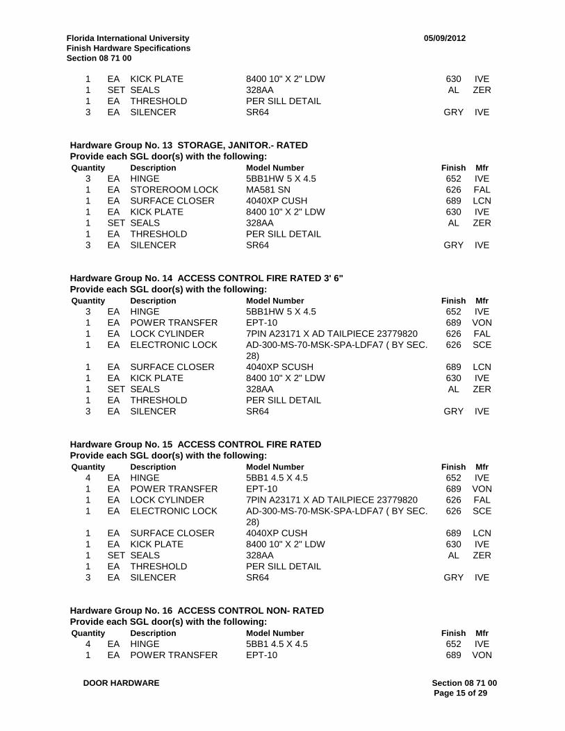
Hardware Group No. 13 STORAGE, JANITOR.- RATEDProvide each SGL door(s) with the following:Quantity Description Model Number Finish Mfr
3 EA HINGE 5BB1HW 5 X 4.5 652 IVE1 EA STOREROOM LOCK MA581 SN 626 FAL1 EA SURFACE CLOSER 4040XP CUSH 689 LCN1 EA KICK PLATE 8400 10" X 2" LDW 630 IVE1 SET SEALS 328AA AL ZER1 EA THRESHOLD PER SILL DETAIL3 EA SILENCER SR64 GRY IVE
Hardware Group No. 14 ACCESS CONTROL FIRE RATED 3' 6"Provide each SGL door(s) with the following:Quantity Description Model Number Finish Mfr
3 EA HINGE 5BB1HW 5 X 4.5 652 IVE1 EA POWER TRANSFER EPT-10 689 VON1 EA LOCK CYLINDER 7PIN A23171 X AD TAILPIECE 23779820 626 FAL1 EA ELECTRONIC LOCK AD-300-MS-70-MSK-SPA-LDFA7 ( BY SEC.
28)626 SCE
1 EA SURFACE CLOSER 4040XP SCUSH 689 LCN1 EA KICK PLATE 8400 10" X 2" LDW 630 IVE1 SET SEALS 328AA AL ZER1 EA THRESHOLD PER SILL DETAIL3 EA SILENCER SR64 GRY IVE
Hardware Group No. 15 ACCESS CONTROL FIRE RATEDProvide each SGL door(s) with the following:Quantity Description Model Number Finish Mfr
4 EA HINGE 5BB1 4.5 X 4.5 652 IVE1 EA POWER TRANSFER EPT-10 689 VON1 EA LOCK CYLINDER 7PIN A23171 X AD TAILPIECE 23779820 626 FAL1 EA ELECTRONIC LOCK AD-300-MS-70-MSK-SPA-LDFA7 ( BY SEC.
28)626 SCE
1 EA SURFACE CLOSER 4040XP CUSH 689 LCN1 EA KICK PLATE 8400 10" X 2" LDW 630 IVE1 SET SEALS 328AA AL ZER1 EA THRESHOLD PER SILL DETAIL3 EA SILENCER SR64 GRY IVE
Hardware Group No. 16 ACCESS CONTROL NON- RATEDProvide each SGL door(s) with the following:Quantity Description Model Number Finish Mfr
4 EA HINGE 5BB1 4.5 X 4.5 652 IVE1 EA POWER TRANSFER EPT-10 689 VON
Florida International University 05/09/2012Finish Hardware SpecificationsSection 08 71 00
DOOR HARDWARE Section 08 71 00Page 16 of 29
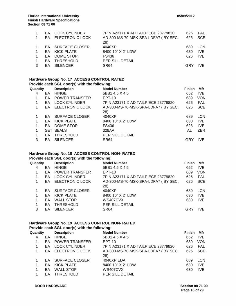
1 EA LOCK CYLINDER 7PIN A23171 X AD TAILPIECE 23779820 626 FAL1 EA ELECTRONIC LOCK AD-300-MS-70-MSK-SPA-LDFA7 ( BY SEC.
28)626 SCE
1 EA SURFACE CLOSER 4040XP 689 LCN1 EA KICK PLATE 8400 10" X 2" LDW 630 IVE1 EA DOME STOP FS436 626 IVE1 EA THRESHOLD PER SILL DETAIL3 EA SILENCER SR64 GRY IVE
Hardware Group No. 17 ACCESS CONTROL RATEDProvide each SGL door(s) with the following:Quantity Description Model Number Finish Mfr
4 EA HINGE 5BB1 4.5 X 4.5 652 IVE1 EA POWER TRANSFER EPT-10 689 VON1 EA LOCK CYLINDER 7PIN A23171 X AD TAILPIECE 23779820 626 FAL1 EA ELECTRONIC LOCK AD-300-MS-70-MSK-SPA-LDFA7 ( BY SEC.
28)626 SCE
1 EA SURFACE CLOSER 4040XP 689 LCN1 EA KICK PLATE 8400 10" X 2" LDW 630 IVE1 EA DOME STOP FS436 626 IVE1 SET SEALS 328AA AL ZER1 EA THRESHOLD PER SILL DETAIL3 EA SILENCER SR64 GRY IVE
Hardware Group No. 18 ACCESS CONTROL NON- RATEDProvide each SGL door(s) with the following:Quantity Description Model Number Finish Mfr
4 EA HINGE 5BB1 4.5 X 4.5 652 IVE1 EA POWER TRANSFER EPT-10 689 VON1 EA LOCK CYLINDER 7PIN A23171 X AD TAILPIECE 23779820 626 FAL1 EA ELECTRONIC LOCK AD-300-MS-70-MSK-SPA-LDFA7 ( BY SEC.
28)626 SCE
1 EA SURFACE CLOSER 4040XP 689 LCN1 EA KICK PLATE 8400 10" X 2" LDW 630 IVE1 EA WALL STOP WS407CVX 630 IVE1 EA THRESHOLD PER SILL DETAIL3 EA SILENCER SR64 GRY IVE
Hardware Group No. 19 ACCESS CONTROL NON- RATEDProvide each SGL door(s) with the following:Quantity Description Model Number Finish Mfr
4 EA HINGE 5BB1 4.5 X 4.5 652 IVE1 EA POWER TRANSFER EPT-10 689 VON1 EA LOCK CYLINDER 7PIN A23171 X AD TAILPIECE 23779820 626 FAL1 EA ELECTRONIC LOCK AD-300-MS-70-MSK-SPA-LDFA7 ( BY SEC.
28)626 SCE
1 EA SURFACE CLOSER 4040XP EDA 689 LCN1 EA KICK PLATE 8400 10" X 2" LDW 630 IVE1 EA WALL STOP WS407CVX 630 IVE1 EA THRESHOLD PER SILL DETAIL
Florida International University 05/09/2012Finish Hardware SpecificationsSection 08 71 00
DOOR HARDWARE Section 08 71 00Page 17 of 29
3 EA SILENCER SR64 GRY IVE
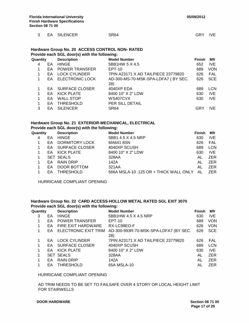
Hardware Group No. 20 ACCESS CONTROL NON- RATEDProvide each SGL door(s) with the following:Quantity Description Model Number Finish Mfr
4 EA HINGE 5BB1HW 5 X 4.5 652 IVE1 EA POWER TRANSFER EPT-10 689 VON1 EA LOCK CYLINDER 7PIN A23171 X AD TAILPIECE 23779820 626 FAL1 EA ELECTRONIC LOCK AD-300-MS-70-MSK-SPA-LDFA7 ( BY SEC.
28)626 SCE
1 EA SURFACE CLOSER 4040XP EDA 689 LCN1 EA KICK PLATE 8400 10" X 2" LDW 630 IVE1 EA WALL STOP WS407CVX 630 IVE1 EA THRESHOLD PER SILL DETAIL3 EA SILENCER SR64 GRY IVE
Hardware Group No. 21 EXTERIOR-MECHANICAL, ELECTRICALProvide each SGL door(s) with the following:Quantity Description Model Number Finish Mfr
4 EA HINGE 5BB1 4.5 X 4.5 NRP 630 IVE1 EA DORMITORY LOCK MA641 8SN 626 FAL1 EA SURFACE CLOSER 4040XP SCUSH 689 LCN1 EA KICK PLATE 8400 10" X 2" LDW 630 IVE1 SET SEALS 328AA AL ZER1 EA RAIN DRIP 142A AL ZER1 EA DOOR BOTTOM 321AA AL ZER1 EA THRESHOLD 566A MSLA-10 .125 OR + THICK WALL ONLY AL ZER
HURRICANE COMPLIANT OPENING
Hardware Group No. 22 CARD ACCESS-HOLLOW METAL RATED SGL EXIT 3070Provide each SGL door(s) with the following:Quantity Description Model Number Finish Mfr
3 EA HINGE 5BB1HW 4.5 X 4.5 NRP 630 IVE1 EA POWER TRANSFER EPT-10 689 VON1 EA FIRE EXIT HARDWARE RX-LC98EO-F 626 VON1 EA ELECTRONIC EXIT TRIM AD-300-993R-70-MSK-SPA-LDFA7 (BY SEC.
28)626 SCE
1 EA LOCK CYLINDER 7PIN A23171 X AD TAILPIECE 23779820 626 FAL1 EA SURFACE CLOSER 4040XP SCUSH 689 LCN1 EA KICK PLATE 8400 10" X 2" LDW 630 IVE1 SET SEALS 328AA AL ZER1 EA RAIN DRIP 142A AL ZER1 EA THRESHOLD 65A MSLA-10 AL ZER
HURRICANE COMPLIANT OPENING
AD TRIM NEEDS TO BE SET TO FAILSAFE OVER 4 STORY OR LOCAL HEIGHT LIMITFOR STAIRWELLS

Florida International University 05/09/2012Finish Hardware SpecificationsSection 08 71 00
DOOR HARDWARE Section 08 71 00Page 18 of 29
Hardware Group No. 23 CARD ACCESS-HOLLOW METAL NON- RATED SGL EXIT 3080Provide each SGL door(s) with the following:Quantity Description Model Number Finish Mfr
4 EA HINGE 5BB1HW 4.5 X 4.5 NRP 630 IVE1 EA POWER TRANSFER EPT-10 689 VON1 EA PANIC HARDWARE HH-RX-LC98EO 626 VON1 EA ELECTRONIC EXIT TRIM AD-300-993R-70-MSK-SPA-LDFA7 (BY SEC.
28)626 SCE
1 EA LOCK CYLINDER 7PIN A23171 X AD TAILPIECE 23779820 626 FAL1 EA SURFACE CLOSER 4040XP EDA 689 LCN1 EA KICK PLATE 8400 10" X 2" LDW 630 IVE1 EA WALL STOP WS443 626 IVE1 SET SEALS 328AA AL ZER1 EA THRESHOLD 65A MSLA-10 AL ZER
HURRICANE COMPLIANT OPENING
AD TRIM NEEDS TO BE SET TO FAILSAFE OVER 4 STORY OR LOCAL HEIGHT LIMITFOR STAIRWELLS
Hardware Group No. 24 FIRE RATED EXIT DEVICE NO LOCKINGProvide each SGL door(s) with the following:Quantity Description Model Number Finish Mfr
4 EA HINGE 5BB1HW 4.5 X 4.5 NRP 630 IVE1 EA FIRE EXIT HARDWARE 98L-BE-F 996L-BE 17 626 VON1 EA SURFACE CLOSER 4040XP EDA 689 LCN1 EA KICK PLATE 8400 10" X 2" LDW 630 IVE1 SET SEALS 328AA AL ZER1 EA THRESHOLD PER SILL DETAIL3 EA SILENCER SR64 GRY IVE
Hardware Group No. 25 CARD ACCESS-HOLLOW METAL RATED SGL EXIT 3080Provide each SGL door(s) with the following:Quantity Description Model Number Finish Mfr
4 EA HINGE 5BB1HW 4.5 X 4.5 NRP 630 IVE1 EA POWER TRANSFER EPT-10 689 VON1 EA FIRE EXIT HARDWARE RX-LC98EO-F 626 VON1 EA ELECTRONIC EXIT TRIM AD-300-993R-70-MSK-SPA-LDFA7 (BY SEC.
28)626 SCE
1 EA LOCK CYLINDER 7PIN A23171 X AD TAILPIECE 23779820 626 FAL1 EA SURFACE CLOSER 4040XP EDA 689 LCN1 EA KICK PLATE 8400 10" X 2" LDW 630 IVE1 EA WALL STOP WS443 626 IVE1 SET SEALS 328AA AL ZER1 EA THRESHOLD 65A MSLA-10 AL ZER
HURRICANE COMPLIANT OPENINGF DEVICE LATCHES EVERY TIME FOR SECURITY

Florida International University 05/09/2012Finish Hardware SpecificationsSection 08 71 00
DOOR HARDWARE Section 08 71 00Page 19 of 29
AD TRIM NEEDS TO BE SET TO FAILSAFE OVER 4 STORY OR LOCAL HEIGHT LIMITFOR STAIRWELLS
Hardware Group No. 26 CARD ACCESS-STOREFRONT WITH OPERATORProvide each PR door(s) with the following:Quantity Description Model Number Finish Mfr
8 EA HINGE 5BB1HW 4.5 X 4.5 NRP 630 IVE2 EA POWER TRANSFER EPT-10 689 VON1 EA PANIC HARDWARE RX-EL9847EO 626 VON1 EA PANIC HARDWARE RX-EL9847NL-OP 626 VON1 EA RIM CYLINDER 951 7PIN 626 FAL2 CUSTOM PULLS PULLS BY DOOR MANUFACTURER1 EA AUTO OPERATOR MAGIC FORCE PAIR DRS SURFACE
MOUNT689 STC
2 EA FLOOR STOP FS444 626 IVE1 EA THRESHOLD 654A AL ZER1 EA POWER SUPPLY PS914 900-4RL GRY SCE1 SET WIRING DIAGRAMS AS REQUIRED
WEATHERSTRIP BY FRAMEMANUFACTURER
1 EA ACTUATOR PACKAGE AS REQUIRED STC1 EA CARD READER SMR20 ( BY SECTION 28) BLK SCE
HURRICANE COMPLIANT OPENINGDOOR PULLS TO BE THRU-BOLTED1.) During business hours both outside and inside actuators are active (button pushed and doorsopen).
2.) After hours (time zones end), inside button always active 24/7. However outside button isinactive. Card has to be swiped in order to activate outside button. Once button is pushed door hardwarewill retract simultaneously with door opening. If button is not pushed after card is swiped door can just bepulled open.
Hardware Group No. 27 CARD ACCESS-STOREFRONTProvide each PR door(s) with the following:Quantity Description Model Number Finish Mfr
8 EA HINGE 5BB1HW 4.5 X 4.5 NRP 630 IVE2 EA POWER TRANSFER EPT-10 689 VON1 EA PANIC HARDWARE RX-EL9847EO 626 VON1 EA PANIC HARDWARE RX-EL9847NL-OP 626 VON1 EA RIM CYLINDER 951 7PIN 626 FAL2 CUSTOM PULLS PULLS BY DOOR MANUFACTURER2 EA SURFACE CLOSER 4040XP 689 LCN2 EA MOUNTING PLATE 4040-18TJ 689 LCN2 EA FLOOR STOP FS444 626 IVE1 EA THRESHOLD 654A AL ZER1 EA POWER SUPPLY PS914 900-4RL GRY SCE1 SET WIRING DIAGRAMS AS REQUIRED
WEATHERSTRIP BY FRAMEMANUFACTURER
Florida International University 05/09/2012Finish Hardware SpecificationsSection 08 71 00
DOOR HARDWARE Section 08 71 00Page 20 of 29
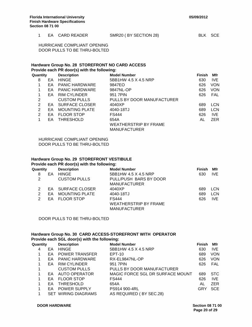
1 EA CARD READER SMR20 ( BY SECTION 28) BLK SCE
HURRICANE COMPLIANT OPENINGDOOR PULLS TO BE THRU-BOLTED
Hardware Group No. 28 STOREFRONT NO CARD ACCESSProvide each PR door(s) with the following:Quantity Description Model Number Finish Mfr
8 EA HINGE 5BB1HW 4.5 X 4.5 NRP 630 IVE1 EA PANIC HARDWARE 9847EO 626 VON1 EA PANIC HARDWARE 9847NL-OP 626 VON1 EA RIM CYLINDER 951 7PIN 626 FAL2 CUSTOM PULLS PULLS BY DOOR MANUFACTURER2 EA SURFACE CLOSER 4040XP 689 LCN2 EA MOUNTING PLATE 4040-18TJ 689 LCN2 EA FLOOR STOP FS444 626 IVE1 EA THRESHOLD 654A AL ZER
WEATHERSTRIP BY FRAMEMANUFACTURER
HURRICANE COMPLIANT OPENINGDOOR PULLS TO BE THRU-BOLTED
Hardware Group No. 29 STOREFRONT VESTIBULEProvide each PR door(s) with the following:Quantity Description Model Number Finish Mfr
8 EA HINGE 5BB1HW 4.5 X 4.5 NRP 630 IVE2 CUSTOM PULLS PULL/PUSH BARS BY DOOR
MANUFACTURER2 EA SURFACE CLOSER 4040XP 689 LCN2 EA MOUNTING PLATE 4040-18TJ 689 LCN2 EA FLOOR STOP FS444 626 IVE
WEATHERSTRIP BY FRAMEMANUFACTURER
DOOR PULLS TO BE THRU-BOLTED
Hardware Group No. 30 CARD ACCESS-STOREFRONT WITH OPERATORProvide each SGL door(s) with the following:Quantity Description Model Number Finish Mfr
4 EA HINGE 5BB1HW 4.5 X 4.5 NRP 630 IVE1 EA POWER TRANSFER EPT-10 689 VON1 EA PANIC HARDWARE RX-EL9847NL-OP 626 VON1 EA RIM CYLINDER 951 7PIN 626 FAL1 CUSTOM PULLS PULLS BY DOOR MANUFACTURER1 EA AUTO OPERATOR MAGIC FORCE SGL DR SURFACE MOUNT 689 STC1 EA FLOOR STOP FS444 626 IVE1 EA THRESHOLD 654A AL ZER1 EA POWER SUPPLY PS914 900-4RL GRY SCE1 SET WIRING DIAGRAMS AS REQUIRED ( BY SEC.28)
Florida International University 05/09/2012Finish Hardware SpecificationsSection 08 71 00
DOOR HARDWARE Section 08 71 00Page 21 of 29
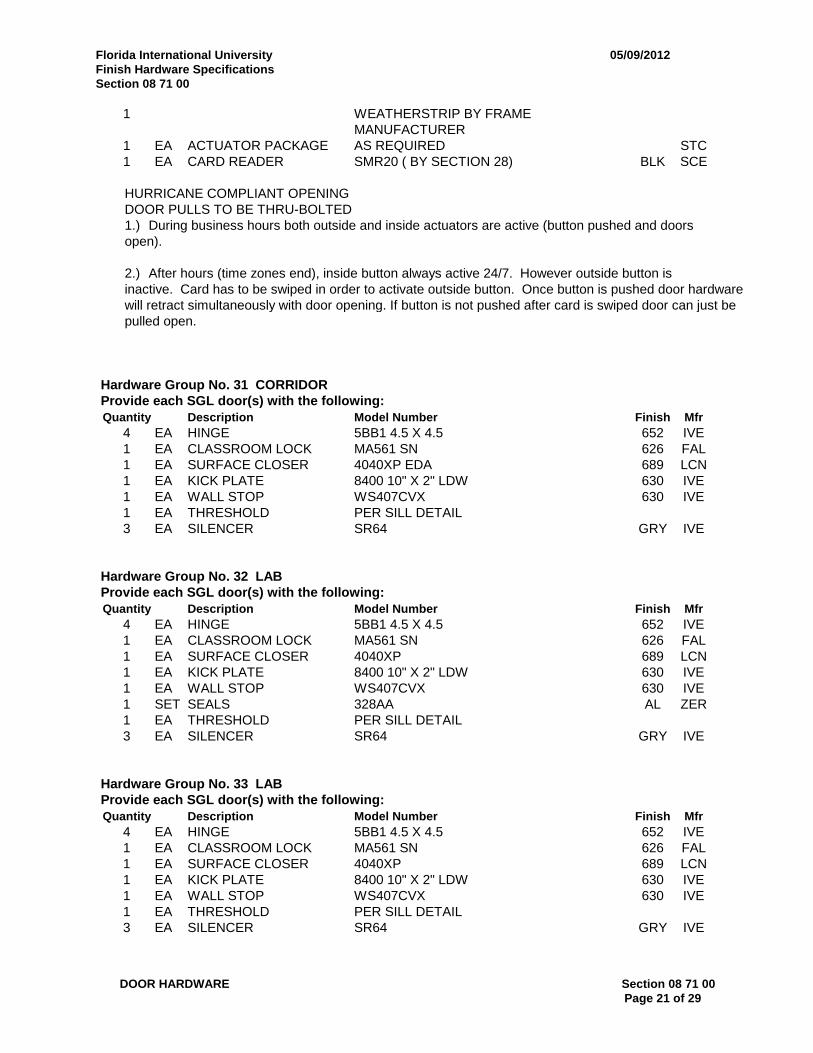
1 WEATHERSTRIP BY FRAMEMANUFACTURER
1 EA ACTUATOR PACKAGE AS REQUIRED STC1 EA CARD READER SMR20 ( BY SECTION 28) BLK SCE
HURRICANE COMPLIANT OPENINGDOOR PULLS TO BE THRU-BOLTED1.) During business hours both outside and inside actuators are active (button pushed and doorsopen).
2.) After hours (time zones end), inside button always active 24/7. However outside button isinactive. Card has to be swiped in order to activate outside button. Once button is pushed door hardwarewill retract simultaneously with door opening. If button is not pushed after card is swiped door can just bepulled open.
Hardware Group No. 31 CORRIDORProvide each SGL door(s) with the following:Quantity Description Model Number Finish Mfr
4 EA HINGE 5BB1 4.5 X 4.5 652 IVE1 EA CLASSROOM LOCK MA561 SN 626 FAL1 EA SURFACE CLOSER 4040XP EDA 689 LCN1 EA KICK PLATE 8400 10" X 2" LDW 630 IVE1 EA WALL STOP WS407CVX 630 IVE1 EA THRESHOLD PER SILL DETAIL3 EA SILENCER SR64 GRY IVE
Hardware Group No. 32 LABProvide each SGL door(s) with the following:Quantity Description Model Number Finish Mfr
4 EA HINGE 5BB1 4.5 X 4.5 652 IVE1 EA CLASSROOM LOCK MA561 SN 626 FAL1 EA SURFACE CLOSER 4040XP 689 LCN1 EA KICK PLATE 8400 10" X 2" LDW 630 IVE1 EA WALL STOP WS407CVX 630 IVE1 SET SEALS 328AA AL ZER1 EA THRESHOLD PER SILL DETAIL3 EA SILENCER SR64 GRY IVE
Hardware Group No. 33 LABProvide each SGL door(s) with the following:Quantity Description Model Number Finish Mfr
4 EA HINGE 5BB1 4.5 X 4.5 652 IVE1 EA CLASSROOM LOCK MA561 SN 626 FAL1 EA SURFACE CLOSER 4040XP 689 LCN1 EA KICK PLATE 8400 10" X 2" LDW 630 IVE1 EA WALL STOP WS407CVX 630 IVE1 EA THRESHOLD PER SILL DETAIL3 EA SILENCER SR64 GRY IVE

Florida International University 05/09/2012Finish Hardware SpecificationsSection 08 71 00
DOOR HARDWARE Section 08 71 00Page 22 of 29
Hardware Group No. 34 LABProvide each SGL door(s) with the following:Quantity Description Model Number Finish Mfr
4 EA HINGE 5BB1 4.5 X 4.5 652 IVE1 EA CLASSROOM LOCK MA561 SN 626 FAL1 EA SURFACE CLOSER 4040XP 689 LCN1 EA MOUNTING PLATE 4040-18 689 LCN1 EA OVERHEAD HOLDER 450H 630 GLY1 EA KICK PLATE 8400 10" X 2" LDW 630 IVE1 EA THRESHOLD PER SILL DETAIL3 EA SILENCER SR64 GRY IVE
Hardware Group No. 35 CARD ACCESS-STOREFRONTProvide each SGL door(s) with the following:Quantity Description Model Number Finish Mfr
4 EA HINGE 5BB1HW 4.5 X 4.5 NRP 630 IVE1 EA POWER TRANSFER EPT-10 689 VON1 EA PANIC HARDWARE RX-EL9847NL-OP 626 VON1 EA RIM CYLINDER 951 7PIN 626 FAL1 CUSTOM PULLS PULLS BY DOOR MANUFACTURER1 EA SURFACE CLOSER 4040XP 689 LCN1 EA MOUNTING PLATE 4040-18TJ 689 LCN1 EA WALL STOP WS443 626 IVE1 EA THRESHOLD 654A AL ZER1 EA POWER SUPPLY PS914 900-4RL GRY SCE1 SET WIRING DIAGRAMS AS REQUIRED ( BY SEC.28)
WEATHERSTRIP BY FRAMEMANUFACTURER
1 EA CARD READER SMR20 ( BY SECTION 28) BLK SCE
HURRICANE COMPLIANT OPENINGDOOR PULLS TO BE THRU-BOLTED
Hardware Group No. 36 IN-SWING EXTERIOR MECHProvide each SGL door(s) with the following:Quantity Description Model Number Finish Mfr
3 EA HINGE 5BB1 4.5 X 4.5 NRP 630 IVE1 EA CLASSROOM LOCK MA431 SN 626 FAL1 EA ELECTROMAGNETIC
LOCKM450P-ATS/LED (BY SEC 28) 628 SCE
1 EA ELECTROMAGNETICLOCK
TJ490 BRACKET (BY SEC. 28) 628 SCE
1 EA SURFACE CLOSER 4040XP 689 LCN1 EA WALL STOP WS407CVX 630 IVE1 SET SEALS 328AA AL ZER1 EA RAIN DRIP 11 AL ZER1 EA RAIN DRIP 142A AL ZER1 EA THRESHOLD 65A MSLA-10 AL ZER1 EA POWER SUPPLY PS902 900-FA ( BY SEC. 28) SCE
Florida International University 05/09/2012Finish Hardware SpecificationsSection 08 71 00
DOOR HARDWARE Section 08 71 00Page 23 of 29
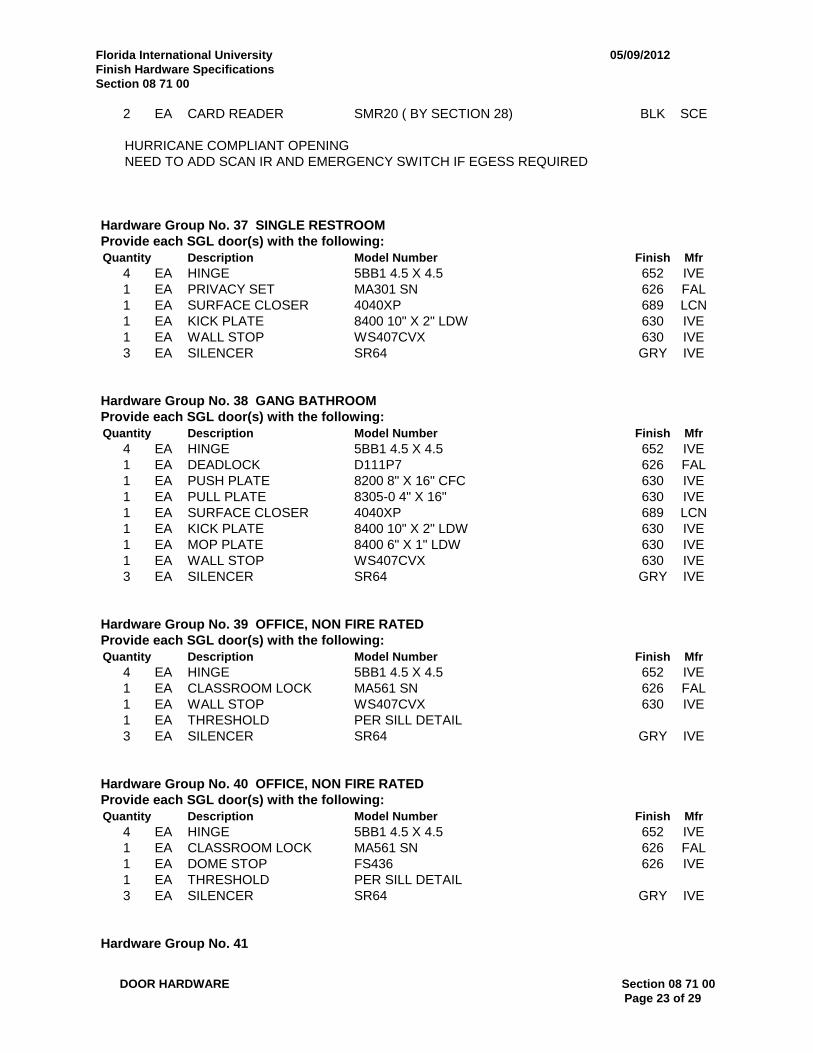
2 EA CARD READER SMR20 ( BY SECTION 28) BLK SCE
HURRICANE COMPLIANT OPENINGNEED TO ADD SCAN IR AND EMERGENCY SWITCH IF EGESS REQUIRED
Hardware Group No. 37 SINGLE RESTROOMProvide each SGL door(s) with the following:Quantity Description Model Number Finish Mfr
4 EA HINGE 5BB1 4.5 X 4.5 652 IVE1 EA PRIVACY SET MA301 SN 626 FAL1 EA SURFACE CLOSER 4040XP 689 LCN1 EA KICK PLATE 8400 10" X 2" LDW 630 IVE1 EA WALL STOP WS407CVX 630 IVE3 EA SILENCER SR64 GRY IVE
Hardware Group No. 38 GANG BATHROOMProvide each SGL door(s) with the following:Quantity Description Model Number Finish Mfr
4 EA HINGE 5BB1 4.5 X 4.5 652 IVE1 EA DEADLOCK D111P7 626 FAL1 EA PUSH PLATE 8200 8" X 16" CFC 630 IVE1 EA PULL PLATE 8305-0 4" X 16" 630 IVE1 EA SURFACE CLOSER 4040XP 689 LCN1 EA KICK PLATE 8400 10" X 2" LDW 630 IVE1 EA MOP PLATE 8400 6" X 1" LDW 630 IVE1 EA WALL STOP WS407CVX 630 IVE3 EA SILENCER SR64 GRY IVE
Hardware Group No. 39 OFFICE, NON FIRE RATEDProvide each SGL door(s) with the following:Quantity Description Model Number Finish Mfr
4 EA HINGE 5BB1 4.5 X 4.5 652 IVE1 EA CLASSROOM LOCK MA561 SN 626 FAL1 EA WALL STOP WS407CVX 630 IVE1 EA THRESHOLD PER SILL DETAIL3 EA SILENCER SR64 GRY IVE
Hardware Group No. 40 OFFICE, NON FIRE RATEDProvide each SGL door(s) with the following:Quantity Description Model Number Finish Mfr
4 EA HINGE 5BB1 4.5 X 4.5 652 IVE1 EA CLASSROOM LOCK MA561 SN 626 FAL1 EA DOME STOP FS436 626 IVE1 EA THRESHOLD PER SILL DETAIL3 EA SILENCER SR64 GRY IVE
Hardware Group No. 41

Florida International University 05/09/2012Finish Hardware SpecificationsSection 08 71 00
DOOR HARDWARE Section 08 71 00Page 24 of 29
Provide each DE door(s) with the following:Quantity Description Model Number Finish Mfr
8 EA HINGE 5BB1 4.5 X 4.5 652 IVE2 CUSTOM PULLS PUSH BARS BY DOOR MANUFACTURER2 EA SURFACE CLOSER 4040XP EDA 689 LCN2 EA MOUNTING PLATE 4040-18PA 689 LCN2 EA FLOOR STOP FS441 626 IVE1 EA THRESHOLD PER SILL DETAIL1 WEATHERSTRIP BY FRAME
MANUFACTURER
Hardware Group No. 42Provide each SGL door(s) with the following:Quantity Description Model Number Finish Mfr
1 EA MORTISE CYLINDER 987 1 3/8 AR CAM 7PIN 626 FAL1 BALANCE OF HARDWARE BY DOOR
SUPPLIER
Hardware Group No. 43Provide each SGL door(s) with the following:Quantity Description Model Number Finish Mfr
1 EA MORTISE CYLINDER 987 1 3/8 STRAIGHT CAM 7PIN 626 FAL1 EA ELECTROMAGNETIC
LOCKHDB420 BRACKET (BY SEC. 28) 628 SCE
1 EA ELECTROMAGNETICLOCK
M420P (BY SEC.28) 628 SCE
1 EA FLOOR STOP FS441 626 IVE1 EA POWER SUPPLY PS902 900-FA ( BY SEC. 28) SCE1 BALANCE OF HARDWARE BY DOOR
SUPPLIER1 EA PUSHBUTTON 621AL EX-DA (BY SEC.28) 630 SCE1 EA SCANNER SCAN II-W WHT SCE1 EA CARD READER SMR20 ( BY SECTION 28) BLK SCE
Hardware Group No. 44Provide each SGL door(s) with the following:Quantity Description Model Number Finish Mfr
2 EA MORTISE CYLINDER 987 1 3/8 AR CAM 7PIN 626 FAL1 EA FLOOR STOP FS441 626 IVE1 BALANCE OF HARDWARE BY DOOR
SUPPLIER
HURRICANE COMPLIANT OPENING
Hardware Group No. 45 EXTERIOR-MECHANICAL, ACCESS CONTROLProvide each PR door(s) with the following:Quantity Description Model Number Finish Mfr
8 EA HINGE 5BB1 4.5 X 4.5 NRP 630 IVE
Florida International University 05/09/2012Finish Hardware SpecificationsSection 08 71 00
DOOR HARDWARE Section 08 71 00Page 25 of 29
1 EA POWER TRANSFER EPT-10 689 VON2 EA SURFACE BOLT SB360T-12 603 IVE1 EA ELECTRONIC LOCK AD-300-MS-70-MSK-SPA-LDFA7 ( BY SEC.
28)626 SCE
2 EA SURFACE CLOSER 4040XP SCUSH 689 LCN2 EA KICK PLATE 8400 10" X 1" LDW 630 IVE1 SET SEALS 328AA AL ZER1 EA RAIN DRIP 142A AL ZER1 EA DOOR BOTTOM 321AA AL ZER1 EA THRESHOLD 566A MSLA-10 .125 OR + THICK WALL ONLY AL ZER
HURRICANE COMPLIANT OPENINGALLOW FOR BOTTOM SURFACE BOLT AND DOOR BOTTOM
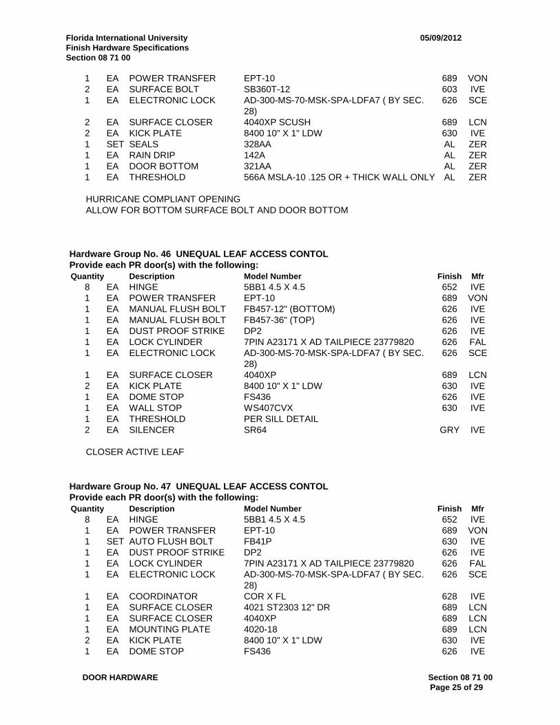
Hardware Group No. 46 UNEQUAL LEAF ACCESS CONTOLProvide each PR door(s) with the following:Quantity Description Model Number Finish Mfr
8 EA HINGE 5BB1 4.5 X 4.5 652 IVE1 EA POWER TRANSFER EPT-10 689 VON1 EA MANUAL FLUSH BOLT FB457-12" (BOTTOM) 626 IVE1 EA MANUAL FLUSH BOLT FB457-36" (TOP) 626 IVE1 EA DUST PROOF STRIKE DP2 626 IVE1 EA LOCK CYLINDER 7PIN A23171 X AD TAILPIECE 23779820 626 FAL1 EA ELECTRONIC LOCK AD-300-MS-70-MSK-SPA-LDFA7 ( BY SEC.
28)626 SCE
1 EA SURFACE CLOSER 4040XP 689 LCN2 EA KICK PLATE 8400 10" X 1" LDW 630 IVE1 EA DOME STOP FS436 626 IVE1 EA WALL STOP WS407CVX 630 IVE1 EA THRESHOLD PER SILL DETAIL2 EA SILENCER SR64 GRY IVE
CLOSER ACTIVE LEAF
Hardware Group No. 47 UNEQUAL LEAF ACCESS CONTOLProvide each PR door(s) with the following:Quantity Description Model Number Finish Mfr
8 EA HINGE 5BB1 4.5 X 4.5 652 IVE1 EA POWER TRANSFER EPT-10 689 VON1 SET AUTO FLUSH BOLT FB41P 630 IVE1 EA DUST PROOF STRIKE DP2 626 IVE1 EA LOCK CYLINDER 7PIN A23171 X AD TAILPIECE 23779820 626 FAL1 EA ELECTRONIC LOCK AD-300-MS-70-MSK-SPA-LDFA7 ( BY SEC.
28)626 SCE
1 EA COORDINATOR COR X FL 628 IVE1 EA SURFACE CLOSER 4021 ST2303 12" DR 689 LCN1 EA SURFACE CLOSER 4040XP 689 LCN1 EA MOUNTING PLATE 4020-18 689 LCN2 EA KICK PLATE 8400 10" X 1" LDW 630 IVE1 EA DOME STOP FS436 626 IVE
Florida International University 05/09/2012Finish Hardware SpecificationsSection 08 71 00
DOOR HARDWARE Section 08 71 00Page 26 of 29
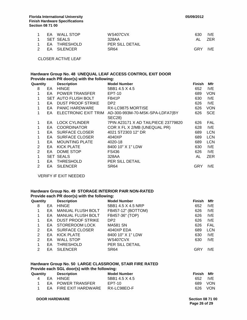
1 EA WALL STOP WS407CVX 630 IVE1 SET SEALS 328AA AL ZER1 EA THRESHOLD PER SILL DETAIL2 EA SILENCER SR64 GRY IVE
CLOSER ACTIVE LEAF
Hardware Group No. 48 UNEQUAL LEAF ACCESS CONTROL EXIT DOORProvide each PR door(s) with the following:Quantity Description Model Number Finish Mfr
8 EA HINGE 5BB1 4.5 X 4.5 652 IVE1 EA POWER TRANSFER EPT-10 689 VON1 SET AUTO FLUSH BOLT FB41P 630 IVE1 EA DUST PROOF STRIKE DP2 626 IVE1 EA PANIC HARDWARE RX-LC9875 MORTISE 626 VON1 EA ELECTRONIC EXIT TRIM AD-300-993M-70-MSK-SPA-LDFA7(BY
SEC28)626 SCE
1 EA LOCK CYLINDER 7PIN A23171 X AD TAILPIECE 23779820 626 FAL1 EA COORDINATOR COR X FL X 2/MB (UNEQUAL PR) 628 IVE1 EA SURFACE CLOSER 4021 ST2303 12" DR 689 LCN1 EA SURFACE CLOSER 4040XP 689 LCN1 EA MOUNTING PLATE 4020-18 689 LCN2 EA KICK PLATE 8400 10" X 1" LDW 630 IVE2 EA DOME STOP FS436 626 IVE1 SET SEALS 328AA AL ZER1 EA THRESHOLD PER SILL DETAIL2 EA SILENCER SR64 GRY IVE
VERIFY IF EXIT NEEDED
Hardware Group No. 49 STORAGE INTERIOR PAIR NON-RATEDProvide each PR door(s) with the following:Quantity Description Model Number Finish Mfr
8 EA HINGE 5BB1 4.5 X 4.5 NRP 652 IVE1 EA MANUAL FLUSH BOLT FB457-12" (BOTTOM) 626 IVE1 EA MANUAL FLUSH BOLT FB457-36" (TOP) 626 IVE1 EA DUST PROOF STRIKE DP2 626 IVE1 EA STOREROOM LOCK MA581 SN 626 FAL2 EA SURFACE CLOSER 4040XP EDA 689 LCN2 EA KICK PLATE 8400 10" X 1" LDW 630 IVE2 EA WALL STOP WS407CVX 630 IVE1 EA THRESHOLD PER SILL DETAIL2 EA SILENCER SR64 GRY IVE
Hardware Group No. 50 LARGE CLASSROOM, STAIR FIRE RATEDProvide each SGL door(s) with the following:Quantity Description Model Number Finish Mfr
4 EA HINGE 5BB1 4.5 X 4.5 652 IVE1 EA POWER TRANSFER EPT-10 689 VON1 EA FIRE EXIT HARDWARE RX-LC98EO-F 626 VON

Florida International University 05/09/2012Finish Hardware SpecificationsSection 08 71 00
DOOR HARDWARE Section 08 71 00Page 27 of 29
1 EA ELECTRONIC EXIT TRIM AD-300-993R-70-MSK-SPA-LDFA7 (BY SEC.28)
626 SCE
1 EA LOCK CYLINDER 7PIN A23171 X AD TAILPIECE 23779820 626 FAL1 EA SURFACE CLOSER 4040XP EDA 689 LCN1 EA KICK PLATE 8400 10" X 2" LDW 630 IVE1 EA WALL STOP WS407CVX 630 IVE1 SET SEALS 328AA AL ZER1 EA THRESHOLD PER SILL DETAIL3 EA SILENCER SR64 GRY IVE
Hardware Group No. 51 LARGE CLASSROOM, STAIR FIRE RATEDProvide each SGL door(s) with the following:Quantity Description Model Number Finish Mfr
4 EA HINGE 5BB1 4.5 X 4.5 652 IVE1 EA POWER TRANSFER EPT-10 689 VON1 EA FIRE EXIT HARDWARE RX-LC98EO-F 626 VON1 EA ELECTRONIC EXIT TRIM AD-300-993R-70-MSK-SPA-LDFA7 (BY SEC.
28)626 SCE
1 EA LOCK CYLINDER 7PIN A23171 X AD TAILPIECE 23779820 626 FAL1 EA SURFACE CLOSER 4040XP CUSH 689 LCN1 EA KICK PLATE 8400 10" X 2" LDW 630 IVE1 SET SEALS 328AA AL ZER1 EA THRESHOLD PER SILL DETAIL3 EA SILENCER SR64 GRY IVE
Hardware Group No. 52 INTERIOR PAIR NON-RATED ACCESS CONTROL UNEQUAL LEAFProvide each PR door(s) with the following:Quantity Description Model Number Finish Mfr
6 EA HINGE 5BB1 4.5 X 4.5 NRP 652 IVE1 EA POWER TRANSFER EPT-10 689 VON1 EA MANUAL FLUSH BOLT FB457-12" (BOTTOM) 626 IVE1 EA MANUAL FLUSH BOLT FB457-36" (TOP) 626 IVE1 EA DUST PROOF STRIKE DP2 626 IVE1 EA LOCK CYLINDER 7PIN A23171 X AD TAILPIECE 23779820 626 FAL1 EA ELECTRONIC LOCK AD-300-MS-70-MSK-SPA-LDFA7 ( BY SEC.
28)626 SCE
2 EA SURFACE CLOSER 4040XP 689 LCN2 EA KICK PLATE 8400 10" X 1" LDW 630 IVE1 EA DOME STOP FS436 626 IVE1 EA WALL STOP WS407CVX 630 IVE1 EA THRESHOLD PER SILL DETAIL2 EA SILENCER SR64 GRY IVE1 Z ASTRAGAL BY DOOR SUPPLIER
MANUAL FLUSH BOLT
Hardware Group No. 53 EXTERIOR ROOF LOCKED BOTH SIDESProvide each SGL door(s) with the following:Quantity Description Model Number Finish Mfr
4 EA HINGE 5BB1HW 4.5 X 4.5 NRP 630 IVE

Florida International University 05/09/2012Finish Hardware SpecificationsSection 08 71 00
DOOR HARDWARE Section 08 71 00Page 28 of 29
1 EA STORE DOOR LOCK MA371 SN 626 FAL1 EA SURFACE CLOSER 4040XP SCUSH 689 LCN1 EA KICK PLATE 8400 10" X 2" LDW 630 IVE1 SET SEALS 328AA AL ZER1 EA RAIN DRIP 142A AL ZER1 EA THRESHOLD 65A MSLA-10 AL ZER
HURRICANE COMPLIANT OPENING
Hardware Group No. 54Provide each SGL door(s) with the following:Quantity Description Model Number Finish Mfr
1 ALL HARDWARE BY DOORMANUFACTURER
VERIFY IF DOORS WILL ACCEPT LOCK CYLINDER
Hardware Group No. 55 ROOF STAIRProvide each SGL door(s) with the following:Quantity Description Model Number Finish Mfr
4 EA HINGE 5BB1 4.5 X 4.5 NRP 630 IVE1 EA DORMITORY LOCK MA571 SN 626 FAL1 EA ELECTROMAGNETIC
LOCKM450P-ATS/LED (BY SEC 28) 628 SCE
1 EA SURFACE CLOSER 4040XP SCUSH 689 LCN1 EA KICK PLATE 8400 10" X 2" LDW 630 IVE1 EA WALL STOP WS407CVX 630 IVE1 SET SEALS 328AA AL ZER1 EA RAIN DRIP 142A AL ZER1 EA THRESHOLD 566A MSLA-10 .125 OR + THICK WALL ONLY AL ZER1 EA POWER SUPPLY PS902 900-FA ( BY SEC. 28) SCE2 EA CARD READER SMR20 ( BY SECTION 28) BLK SCE
Hardware Group No. 56 EXTERIOR-ROOFProvide each SGL door(s) with the following:Quantity Description Model Number Finish Mfr
3 EA HINGE 5BB1 4.5 X 4.5 NRP 630 IVE1 EA DORMITORY LOCK MA641 8SN 626 FAL1 EA SURFACE CLOSER 4040XP SCUSH 689 LCN1 SET SEALS 328AA AL ZER1 EA RAIN DRIP 142A AL ZER2 EA DOOR BOTTOM 321AA AL ZER1 EA THRESHOLD 566A MSLA-10 .125 OR + THICK WALL ONLY AL ZER
HURRICANE COMPLIANT OPENING
Hardware Group No. 57 EXTERIOR-ROOFProvide each SGL door(s) with the following:

Florida International University 05/09/2012Finish Hardware SpecificationsSection 08 71 00
DOOR HARDWARE Section 08 71 00Page 29 of 29
Quantity Description Model Number Finish Mfr
4 EA HINGE 5BB1 4.5 X 4.5 NRP 630 IVE1 EA DORMITORY LOCK MA641 8SN 626 FAL2 EA SURFACE CLOSER 4040XP SCUSH 689 LCN1 SET SEALS 328AA AL ZER1 EA RAIN DRIP 142A AL ZER2 EA DOOR BOTTOM 321AA AL ZER1 EA THRESHOLD 566A MSLA-10 .125 OR + THICK WALL ONLY AL ZER
HURRICANE COMPLIANT OPENING
END OF SECTION

PDF created by SpeXra Page 1
Catalog Cutsfor
FLORIDA INTERNATIONAL UNIVERSITY- A/E SERVICES DEPT
Sorted by Manufacturer
Prepared ByBILL WHITCOMB AHC/CDC
IR SECURITY TECHNOLOGIES111 D BENT ARROW DR
JUPITER FL 33458Phone561-747-3029 Fax 1-866-256-7342
Created 10/11/2012

Project: Control #: 4143 Print Date: 10/11/2012 4:32:07 PM
Supplier: IR Security Technologies Revision #: 1 Rev Date: 10/11/2012 4:31:04 PM
Page 2 of 3
Catalog Cut Summary
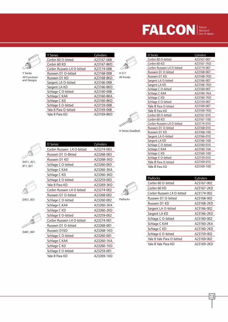
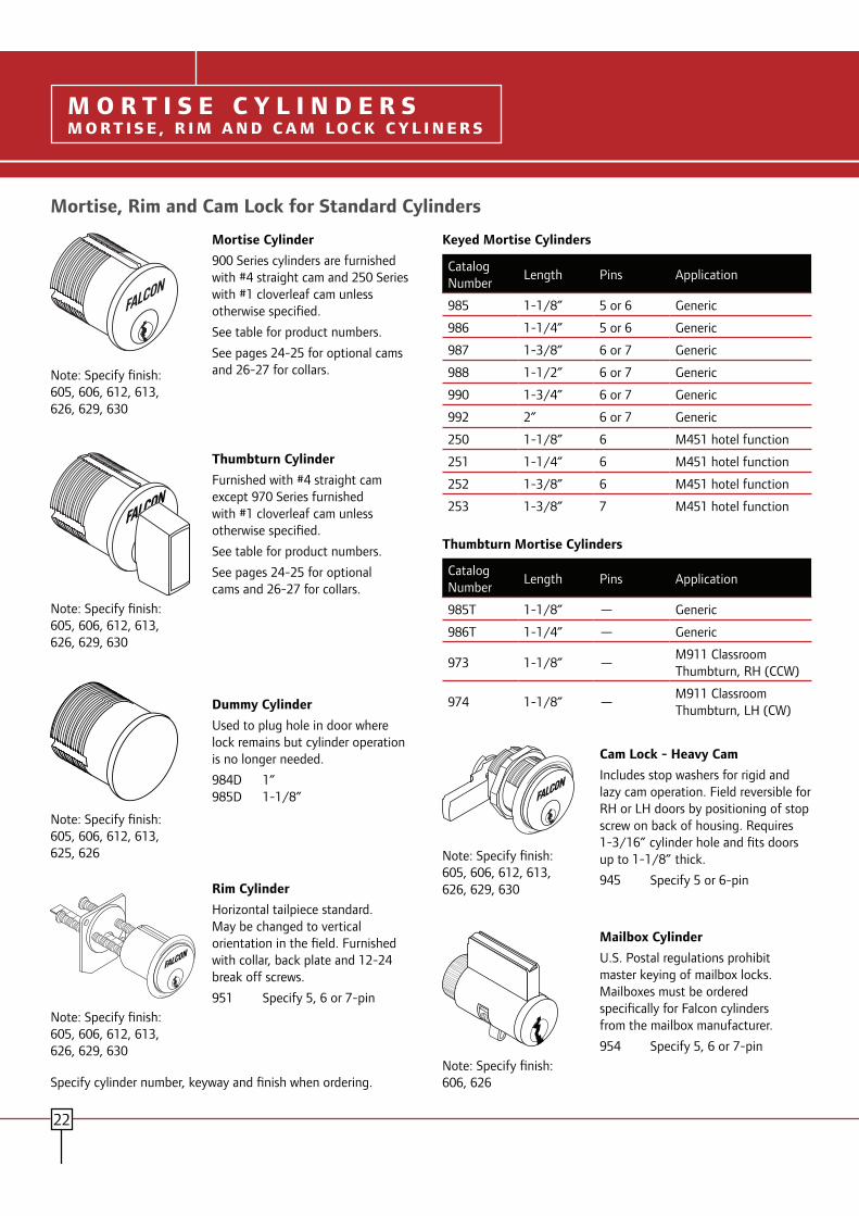
Mfr Description Item Id Catalog Number Cut FAL RIM CYLINDER 951 FAL_CYL_MortiseRimFAL MORTISE CYLINDER 987 FAL_CYL_MortiseRimFAL 7-PIN SERIES CYL
AD TAILPIECEA23171 FAL_CYL_Cylindrical
FAL CLASSRM DEADBOLT
D111P7 FAL_0031
FAL PASSAGE SET MA101 SN FAL_MAFAL PRIVACY LOCK MA301 SN FAL_MAFAL CLASSROOM LOCK MA561P7 SN FAL_MAFAL STOREROOM LOCK MA581P7 8SN SN FAL_MAFAL STOREROOM LOCK MA581P7 SN FAL_MAFAL DORMITORY LOCK MA641P7 8SN SN FAL_MAGLY OH STOP 450S GLY_0006GLY OH STOP 90S GLY_0003IVE HINGE 5BB1 4.5 X 4.5 IVE_0250IVE HINGE 5BB1 4.5 X 4.5 NRP IVE_0250IVE HINGE 5BB1 4.5 X 4.5 NRP IVE_0250IVE HW HINGE 5BB1HW 4.5 X 4.5 NRP IVE_0251IVE DOOR PULL, 1"
ROUND8103EZ 10" O IVE_0086-IVE_0121-IVE_5002
IVE PUSH PLATE 8200 4"X16" IVE_0127IVE KICK PLATE 8400 10" X 2" LDW IVE_0223IVE KICK PLATE 8400 10" X 2" LDW IVE_0223IVE COORDINATOR COR X FL IVE_0101IVE DUST PROOF STRIKE DP2 IVE_0098IVE AUTO FLUSH BOLT FB31P IVE_0090IVE AUTO FLUSH BOLT FB41P IVE_0091IVE MANUAL FLUSH
BOLTFB457 IVE_0096
IVE MANUAL FLUSH BOLT
FB458 IVE_0097
IVE FLOOR STOP FS436 IVE_0227IVE FLOOR STOP FS441 IVE_0132IVE FLOOR STOP FS444 IVE_0133IVE SURFACE BOLT SB360 T 12" IVE_0153IVE SILENCER SR64-1 IVE_0148IVE WALL STOP WS407CVX IVE_0141IVE WALL STOP WS443 IVE_0144LCN SURFACE CLOSER 4040XP LCN_4040XPLCN SURFACE CLOSER 4040XP EDA LCN_4040XPSCE ELECT
CLASSROOM/STOREROOM LOCK
AD-300-993R-70-MSK-SPA-626-LDFA7 AS LLL
SCE_0078-SCE_0124-SCE_0124-SCE_0124

Project: Control #: 4143 Print Date: 10/11/2012 4:32:07 PM
Supplier: IR Security Technologies Revision #: 1 Rev Date: 10/11/2012 4:31:04 PM
Page 3 of 3
Mfr Description Item Id Catalog Number Cut SCE ELECT
CLASSROOM/STOREROOM LOCK
AD-300-993S-70-MSK-SPA-626-LDFA7 AS LLLRX
SCE_0078-SCE_0124-SCE_0124-SCE_0124-SCE_0124
SCE ELECT CLASSROOM/STOREROOM LOCK
AD-300-MS-70-MSK-8SP-626-LDFA7 4B
SCE_0078
SCE ELECT CLASSROOM/STOREROOM LOCK
AD-300-MS-70-MSK-SPA-626-LDFA7 4B
SCE_0078
SCE ELECT DUMMY TRIM LOCK
AD-993DT--SPA-626-PD SCE_0124
SCE POWER SUPPLY PS902 SCE_0087SCE CARD READER SMR20 SCE_0011VON ELEC PANIC
HARDWARELX-LC-XP-98-EO VON_9899_006-
VON_9899_041-VON_9899_007-VON_SEC_017
VON POWER SUPPLY PS914 900-2RS-FA VON_0111VON ELEC PANIC
HARDWARERX-EL-9847-EO VON_9899_022-
VON_9899_041-VON_9899_023-VON_SEC_017
VON ELEC PANIC HARDWARE
RX-EL-9847-NL-OP VON_9899_022-VON_9899_041-VON_9899_023-VON_SEC_017
VON ELEC FIRE EXIT HARDWARE
RX-LC-98-EO-F VON_9899_008-VON_9899_041-VON_9899_009-VON_SEC_017
VON ELEC FIRE EXIT HARDWARE
RX-LC-98-EO-F-SNB VON_9899_008-VON_9899_041-VON_9899_009-VON_SEC_017-VON_AUX_008-VON_AUX_009
ZER RAIN DRIP 142A ZER_0076ZER SEALS 188S ZER_0080ZER SEALS 328AA 1/36" 2/84" ZER_0070ZER DOOR BOTTOM 367AA ZER_0067ZER THRESHOLD 566A 36" MSLA-10 ZER_0058ZER THRESHOLD 65A 36" MSLA-10 ZER_0058


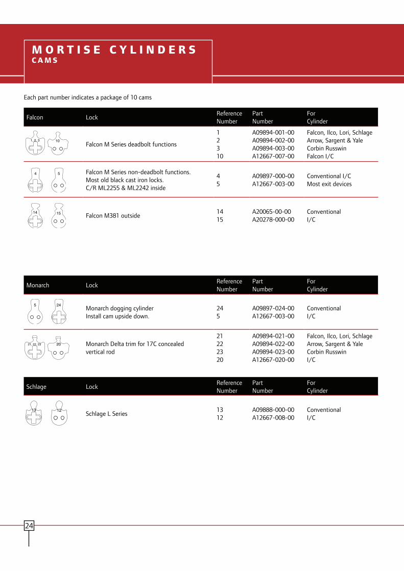
4 5
1, 2, 3 10
14 15
245
21, 22, 23 20
13 12

6 8
16 9
11
27
25
26 7
CAM KIT

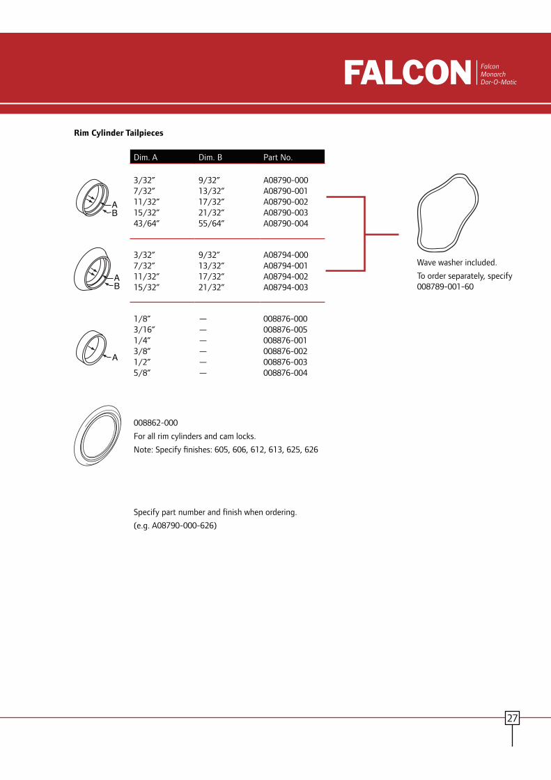
AB
AB
A

MA Series Grade 1 Mortise Lever and Knob Locks
FalconMonarchDor-O-Matic

2
S A F E T Y , S E C U R I T Y A N D U N C O M P R O M I S I N G V A L U E
At Falcon, we know that every product you sell not only has to meet
local building codes, but also your expectations for performance and
quality. We take your expectations seriously, and that’s why we build our
locks to deliver durability, convenience and unmatched value. After all,
we’ve built our reputation on the same standards that you have
– providing quality products at a reasonable price, delivered on time.
It’s the way we do business and it’s what makes Falcon locks a powerful
choice no matter what your project.
2
T H E F A L C O N D I F F E R E N C E

3
S A F E T Y , S E C U R I T Y A N D U N C O M P R O M I S I N G V A L U E
F E A T U R E S
The Falcon MA Series lock delivers high performance at an affordable cost
in your office, hospital, education or other commercial projects. One of
Falcon’s toughest, most dependable locks, the MA Series provides security
and is built to stand up to constant use without fail. The MA Series also
makes retrofit easy with an interchangeable core that can be removed
for quick, easy re-keying and is compatible with SFIC products from
other manufacturers. And they’re backed by one of the best names
in the business.
Cold-formed steel, zinc plated with dichromate for corrosion resistance
Solid brass cylinder and plug
Field reversible trim*
Reversible handing without opening lock chassis case
Forged escutcheon for added strength**
Two piece stainless steel anti-friction latch bolt
3
F A L C O N M A S E R I E S
1” Stainless steel deadbolt
* Excludes MA551** For 605, 606, 613, 625 and 626

Lock Features Falcon Mortise Lock SpecificationsDoor thickness: Standard accommodates thickness of 1-3/8” to 2-1/2”.Backset: 2-3/4” only.Case: Cold formed steel, zinc dichromate plated, .090” thick. Optional lead wrapping available.Hubs: Hardened steel.Handing: Right hand is standard; left hand optional. Reversible in the field.Cylinders: Solid brass cylinder and plug. 5, 6 or 7-pin are available on standard cylinders. 6 or 7-pin are available on interchangeable core cylinder. Furnished with two nickel silver keys standardKeyways: “G” keyway standard on standard cylinder. “A” keyway standard on I/C cylinder. See price book for optional keywaysBind Resistant Trim: Heavy-duty through-bolted inserts clamp the trim on the door assuring proper alignment. Provided with 8-32 screws for strength and thread sealant to prevent loosening.Latch Bolt: Two-piece stainless steel, mechanical anti-friction bolt. 3/4” projection. Dead Bolt: 1” throw, stainless steel with two 13/16” diameter hardened steel, free-turning, saw-resistant roller.Faceplates: (Armored Front) 1-1/4” x 8” brass or stainless steel adjustable for door bevel. Reinforced by heavy gauge steel with stabilizing ribs.Strike: Brass or stainless steel. Meets ANSI AII5.1 for frame preparation. Strike is non-handed. Electrified Functions: Available in 12 or 24 VDC.ANSI/BHMA: Meets ANSI/BHMA 156.13, Series 1000.UL: 3 hour A label.
• Provide mortise locksets that comply with ANSI A156.13, Series 1000, Operational Grade 1 and Security Grade 1 with all standard trims and conventional mortise cylinders. • Locksets comply with UL10B - neutral pressure and UL10C/UBC 7-2 – positive pressure testing requirements. All locks shall be UL listed for 3 hour fire door.• Lock case shall be non-handed, reversible without opening the lock case, and shall be manufactured of zinc dichromate plated steel. Lock case shall be interchangeable for knob or lever applications without modifying the chassis, and shall be constructed with a screw configuration that limits access to operating parts.• Latchbolt shall be 2-piece anti-friction type manufactured from stainless steel, with a standard 2¾” backset, a full ¾” throw and be field reversible. Deadbolt shall have 1” throw and shall be constructed of stainless steel, incorporating two 3/16” diameter security roller pins.• All trim shall be cast, forged, or wrought and through-bolted with thread patch coated screws. Lever trim to have individual heavy duty springs for lever return, and independent rotation in both directions. Return to door style levers meets the ½” California State Fire Marshall requirement.• Spindles to be independent, designed to ‘break-away’ at a maximum of 480 in./lbs. to prevent damage to the lock chassis.• Provide standard non-handed curved lip strikes.• Cylinders to be secured by a dual retainer.• Acceptable manufacturer: FALCON Lock
M A S E R I E SLO C K F E AT U R E S A N D S P E C I F I C AT I O N S
4

7
6
1 2
8
9
3
5
4
12
11
10
13
M A S e r i e sD I M E N S I O N S
5
Lock Dimension1 6” (152mm)2 3-39/64” (92mm)3 2-27/64” (62mm)4 1-3/16” (30mm)5 19/32” (15mm)6 1/4” (6mm)7 1” (25mm)8 1” (26mm)9 1-17/64” (32mm)10 3-49/64” (96mm)11 3/4” (19mm)12 2-3/4” (70mm)13 4-5/32” (106mm)
Faceplate Dimension14 8” (203mm)15 6-3/8” (162mm)16 9/16” (14mm)17 1-9/64” (29mm)18 45/64” (18mm)19 1-1/32” (26mm)20 1/4” (6mm)21 11/32” (9mm)22 1-1/4” (31mm)23 1-27/32” (47mm)24 2-7/16” (62mm)25 3-21/32” (93mm)26 25/32” (20mm)
Strike (A) Door Thickness Lip Size1-3/4” 1-1/4” (32mm)2” 1-7/16” (37mm)2-1/4” 1-9/16” (40mm)2-1/2” 1-11/16” (43mm)
14
15 17
19
25
2423
26
22
18
2120
16
4-7/8"(124mm)
4-1/8"(106mm)
1-1/4"(32mm)
A
Lock Faceplate Strike

41/2"
21/2"29/16"2-9/16”
A
B
8-1/8”
B
2-1/4"
A
M A S e r i e sL E V E R S / K N O B A N D T R I M S
AGAvalon-Gala
DGDane-Gala
6
Cast or forged levers (Avalon, Dane and Quantum) and wrought brass or stainless levers (Sutro), wrought rose and forged or wrought escutcheons are standard.
Lever Trim
GGala Rose
NNapa Escutcheon
Wrought knobs, wrought roses and forged or wrought escutcheons are standard.
Knob Trim
QGQuantum-Gala
SGSutro-Gala
Number A - Width B - Projection AG 4-1/2” 2-7/8” DG 4-1/2” 2-1/2” QG 4-3/4” 3” SG 4-7/8” 3”
Number A - Width B - Projection AN 4-1/2” 2-7/8” DN 4-1/2” 2-1/2” QN 4-3/4” 3” SN 4-7/8” 3”
HGHana-GalaGala - RoseHana - Knob
HNHana-NapaN - EscutcheonH - Knob
2-9/16”
2-11/16”
2-1/4”
8-1/8”
2-11/16”
Falcon MA Series is available in several design combinations; “G” Gala rose or “N” Napa escutcheon and “H” Hana knob designation or four levers “A” Avalon, “D” Dane, “Q” Quantum and “S” Sutro. When specifying, example: AN, Avalon (A) lever - with Napa (N) escutcheon.
7
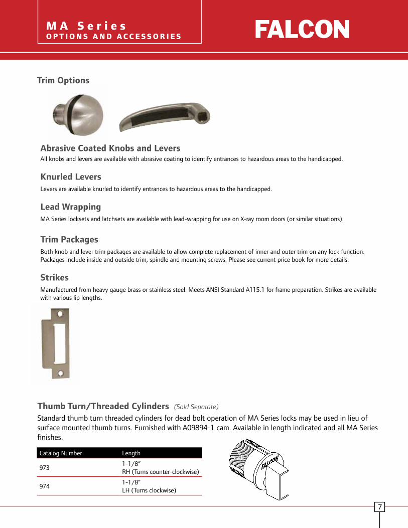
All knobs and levers are available with abrasive coating to identify entrances to hazardous areas to the handicapped.
Knurled LeversLevers are available knurled to identify entrances to hazardous areas to the handicapped.
Lead WrappingMA Series locksets and latchsets are available with lead-wrapping for use on X-ray room doors (or similar situations).
Trim PackagesBoth knob and lever trim packages are available to allow complete replacement of inner and outer trim on any lock function. Packages include inside and outside trim, spindle and mounting screws. Please see current price book for more details.
StrikesManufactured from heavy gauge brass or stainless steel. Meets ANSI Standard A115.1 for frame preparation. Strikes are available with various lip lengths.
Abrasive Coated Knobs and Levers
Trim Options
M A S e r i e sO P T I O N S A N D A C C E S S O R I E S
Thumb Turn/Threaded Cylinders (Sold Separate)
Standard thumb turn threaded cylinders for dead bolt operation of MA Series locks may be used in lieu of surface mounted thumb turns. Furnished with A09894-1 cam. Available in length indicated and all MA Series finishes.
Catalog Number Length
9731-1/8” RH (Turns counter-clockwise)
9741-1/8” LH (Turns clockwise)
M A S e r i e sO p t i o n s a n d A c c e s s o r i e s
M A S e r i e sF U N C T I O N S
8
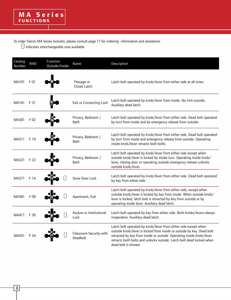
To order Falcon MA Series locksets, please consult page 17 for ordering information and assistance.
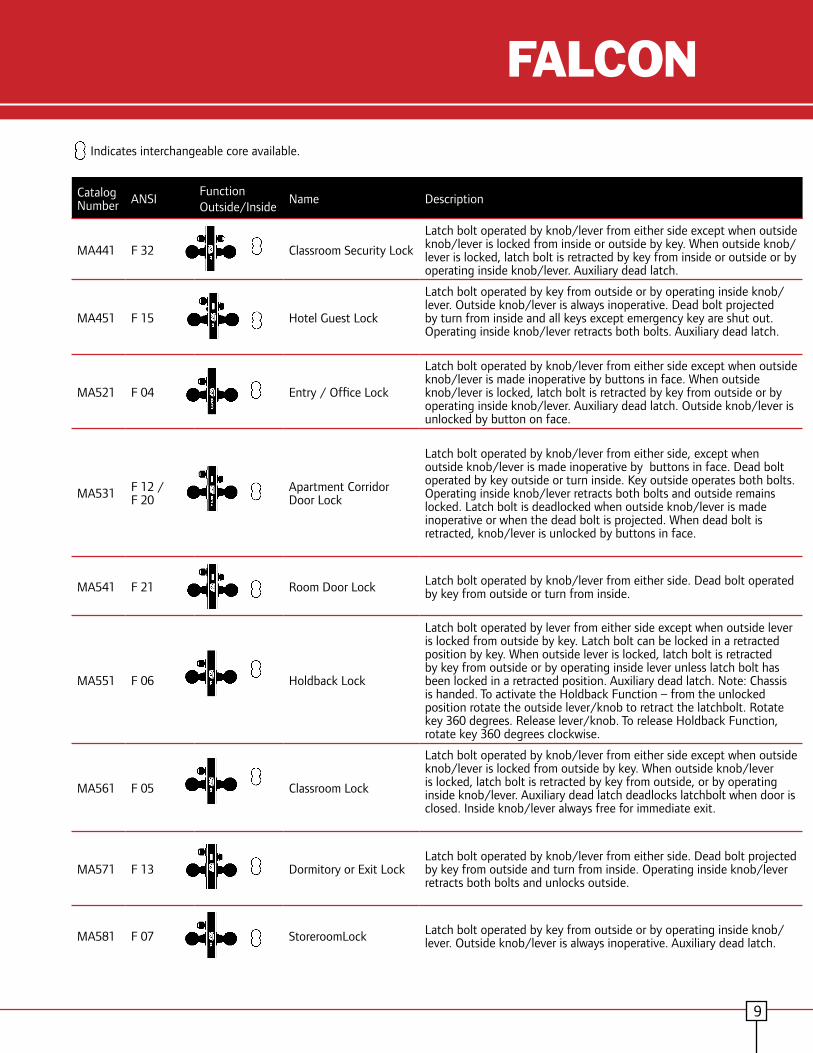
Indicates interchangeable core available.
Catalog Number
ANSIFunctionOutside/Inside
Name Description
MA101 F 01
Passage or Closet Latch
Latch bolt operated by knob/lever from either side at all times.
MA161 F 31 Exit or Connecting LockLatch bolt operated by knob/lever from inside. No trim outside. Auxiliary dead latch.
MA301 F 02Privacy, Bedroom / Bath
Latch bolt operated by knob/lever from either side. Dead bolt operated by turn from inside and by emergency release from outside.
MA311 F 19Privacy, Bedroom / Bath
Latch bolt operated by knob/lever from either side. Dead bolt operated by turn from inside and emergency release from outside. Operating inside knob/lever retracts both bolts.
MA321 F 22Privacy, Bedroom / Bath
Latch bolt operated by knob/lever from either side except when outside knob/lever is locked by inside turn. Operating inside knob/lever, closing door or operating outside emergency release unlocks outside knob/lever.
MA371 F 14 Store Door LockLatch bolt operated by knob/lever from either side. Dead bolt operated by key from either side.
MA381 F 09 Apartment, Exit
Latch bolt operated by knob/lever from either side, except when outside knob/lever is locked by key from inside. When outside knob/lever is locked, latch bolt is retracted by key from outside or by operating inside lever. Auxiliary dead latch.
MA411 F 30Asylum or Institutional Lock
Latch bolt operated by key from either side. Both knobs/levers always inoperative. Auxiliary dead latch.
MA431 F 34Classroom Security with Deadbolt
Latch bolt operated by knob/lever from either side except when outside knob/lever is locked from inside or outside by key. Dead bolt retracted by key from inside or outside. Operating inside knob/lever retracts both bolts and unlocks outside. Latch bolt dead locked when dead bolt is thrown.
9
Catalog Number ANSI
FunctionOutside/Inside
Name Description
MA441 F 32 Classroom Security Lock
Latch bolt operated by knob/lever from either side except when outside knob/lever is locked from inside or outside by key. When outside knob/lever is locked, latch bolt is retracted by key from inside or outside or by operating inside knob/lever. Auxiliary dead latch.
MA451 F 15 Hotel Guest Lock
Latch bolt operated by key from outside or by operating inside knob/lever. Outside knob/lever is always inoperative. Dead bolt projected by turn from inside and all keys except emergency key are shut out. Operating inside knob/lever retracts both bolts. Auxiliary dead latch.
MA521 F 04 Entry / Office Lock
Latch bolt operated by knob/lever from either side except when outside knob/lever is made inoperative by buttons in face. When outside knob/lever is locked, latch bolt is retracted by key from outside or by operating inside knob/lever. Auxiliary dead latch. Outside knob/lever is unlocked by button on face.
MA531 F 12 / F 20
Apartment Corridor Door Lock
Latch bolt operated by knob/lever from either side, except when outside knob/lever is made inoperative by buttons in face. Dead bolt operated by key outside or turn inside. Key outside operates both bolts. Operating inside knob/lever retracts both bolts and outside remains locked. Latch bolt is deadlocked when outside knob/lever is made inoperative or when the dead bolt is projected. When dead bolt is retracted, knob/lever is unlocked by buttons in face.
MA541 F 21 Room Door Lock Latch bolt operated by knob/lever from either side. Dead bolt operated by key from outside or turn from inside.
MA551 F 06 Holdback Lock
Latch bolt operated by lever from either side except when outside lever is locked from outside by key. Latch bolt can be locked in a retracted position by key. When outside lever is locked, latch bolt is retracted by key from outside or by operating inside lever unless latch bolt has been locked in a retracted position. Auxiliary dead latch. Note: Chassis is handed. To activate the Holdback Function – from the unlocked position rotate the outside lever/knob to retract the latchbolt. Rotate key 360 degrees. Release lever/knob. To release Holdback Function, rotate key 360 degrees clockwise.
MA561 F 05 Classroom Lock
Latch bolt operated by knob/lever from either side except when outside knob/lever is locked from outside by key. When outside knob/lever is locked, latch bolt is retracted by key from outside, or by operating inside knob/lever. Auxiliary dead latch deadlocks latchbolt when door is closed. Inside knob/lever always free for immediate exit.
MA571 F 13 Dormitory or Exit LockLatch bolt operated by knob/lever from either side. Dead bolt projected by key from outside and turn from inside. Operating inside knob/lever retracts both bolts and unlocks outside.
MA581 F 07 StoreroomLock Latch bolt operated by key from outside or by operating inside knob/lever. Outside knob/lever is always inoperative. Auxiliary dead latch.
Indicates interchangeable core available.
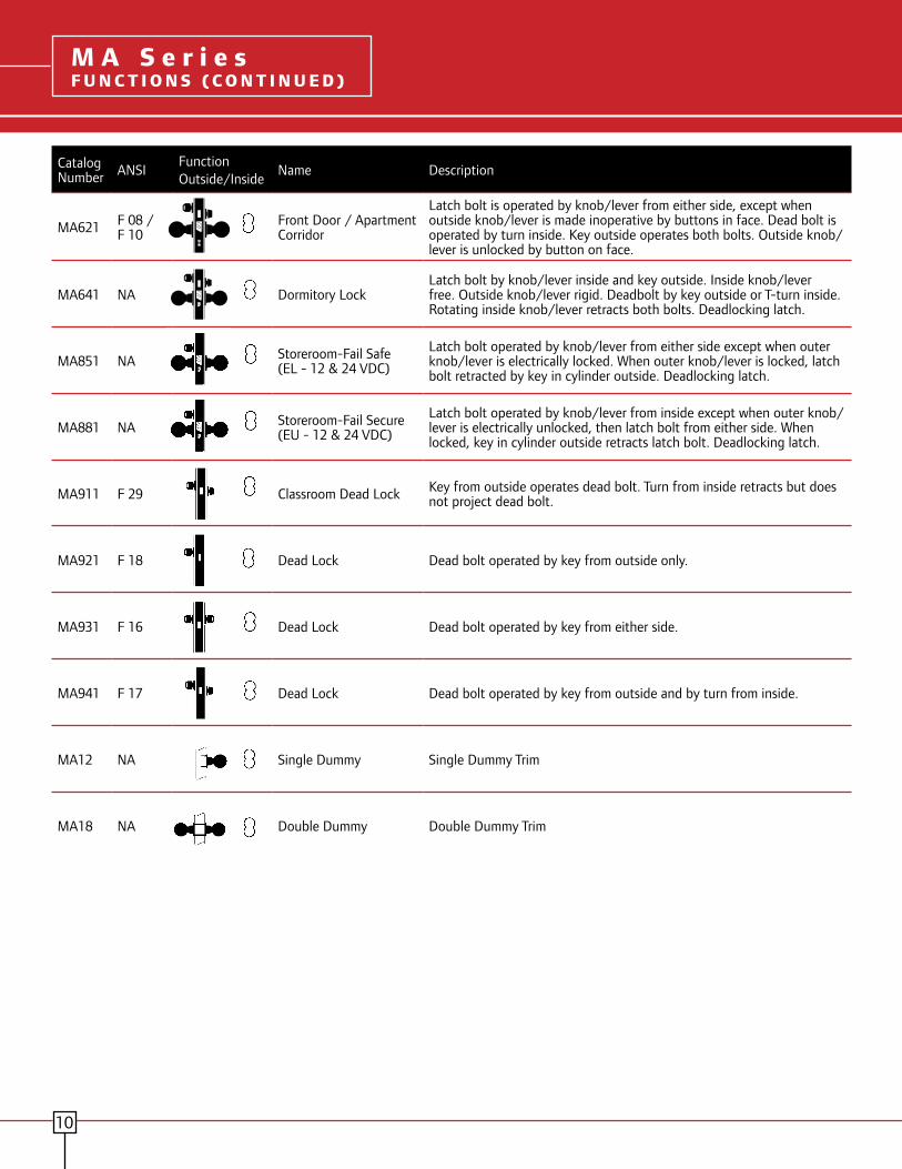
Catalog Number ANSI
FunctionOutside/Inside
Name Description
MA621 F 08 / F 10
Front Door / Apartment Corridor
Latch bolt is operated by knob/lever from either side, except when outside knob/lever is made inoperative by buttons in face. Dead bolt is operated by turn inside. Key outside operates both bolts. Outside knob/lever is unlocked by button on face.
MA641 NA Dormitory LockLatch bolt by knob/lever inside and key outside. Inside knob/lever free. Outside knob/lever rigid. Deadbolt by key outside or T-turn inside. Rotating inside knob/lever retracts both bolts. Deadlocking latch.
MA851 NA Storeroom-Fail Safe (EL - 12 & 24 VDC)
Latch bolt operated by knob/lever from either side except when outer knob/lever is electrically locked. When outer knob/lever is locked, latch bolt retracted by key in cylinder outside. Deadlocking latch.
MA881 NA Storeroom-Fail Secure (EU - 12 & 24 VDC)
Latch bolt operated by knob/lever from inside except when outer knob/lever is electrically unlocked, then latch bolt from either side. When locked, key in cylinder outside retracts latch bolt. Deadlocking latch.
MA911 F 29 Classroom Dead Lock Key from outside operates dead bolt. Turn from inside retracts but does not project dead bolt.
MA921 F 18 Dead Lock Dead bolt operated by key from outside only.
MA931 F 16 Dead Lock Dead bolt operated by key from either side.
MA941 F 17 Dead Lock Dead bolt operated by key from outside and by turn from inside.
MA12 NA Single Dummy Single Dummy Trim
MA18 NA Double Dummy Double Dummy Trim
M A S e r i e sF u n c t i o n s M A S e r i e sF U N C T I O N S ( C O N T I N U E D )
10

11
MA Series Grade 1 Mortise Locks
ANSI No./Grade Function Falcon Arrow Best Cal-
RoyalCorbin/ Russwin Dorma Marks Sargent Yale
F 01 MA101 Passage or Closet Latch A-B01 45N M8010 ML2010 9010 5-55N 8215 8801
F 02 MA301 Privacy, Bedroom / Bath - 45LB M8040 ML2020 - 5-55L 8268 -
F 04 MA521 Entry Lock A-B22 45A M8050 Ml2051 9050 5-55E 8205 8807
F 05 MA561 Classroom Lock A-B17 35R M8070 ML2055 9070 5-55J 8237 8808
F 06 MA551 Holdback Lock - 45RHB - ML2056 9076 5-55JM/JR 8289 8824
F 07 MA581 Storeroom / Closet Lock A-B12 45ED M8080 ML2057 9080 5-55EW 8204 8805
F 08 / F 10 MA621 Front Door / Apartment Corridor A-B21 45BA - ML2048 - 5-55A 8247 8747
F 09 MA381 Apartment, Exit A-B32 45C M8060 ML2042 9060 5-55G 8216 8817-2
F12 / F 20 MA531 Apartment Corridor Door Lock A-B20 45AB M8453 ML2067 9953 5-55FD 8243 8847
F 13 MA571 Dormitory or Exit Lock A-B19 45FT M8456 ML2065 9956 5-55FW 8225 8822
F 14 MA371 Store Door Lock A-B31 45G M8466 ML2022 9966 5-55C 8226 8860-2
F 15 MA451 Hotel Guest Lock A-B15 /16 45H/HJ - ML2029 9985 5-55H 8250 8820
F 16 MA931 Dead Lock A-B42 45WD - ML2012 9962 5-55T 8222 8814-2
F 17 MA941 Dead Lock A-B41 45AD - ML2013 9960 5-55P 8221 8815
F 18 MA921 Dead Lock A-B40 45YD - ML2011 9961 5-55S 8220 8814
F 19 MA311 Privacy, Bedroom / Bath A-B02 45L M8040 ML2030 9940 5-55LF 8266 8802
F 21 MA541 Room Door Lock A-B13 45B M8473 ML2024 9973 5-55B 8224 8860
F 22 MA321 Privacy, Bedroom / Bath A-B26 - M8040 ML2060 9040 5-55LJ 8265 8862
F 29 MA911 Classroom Dead Lock - 45RD - - 9963 5-55SC 8203 8813ST
F 30 MA411 Asylum or Institutional Lock A-B33 45W - - 9082 5-55WW 8217 8830-2
F 31 MA161 Exit or Cummunicating Lock - 45Y - - 9025 5-55EX 8213 8828
F 32 MA441 Intruder Latch Bolt Lock A-B37 45INL - ML2052 9071 5-55GC 8238 8808-2
F 34 MA431 Intruder Dead Bolt Lock - - - - 9967 - 8240 8812-2
NA MA12 Single Dummy 451DT M8170 ML2050 - - 8293 855/855FL
NA MA18 Double Dummy - 452DT - ML2070 - - 8294 836B/838FL
NA MA851 Storeroom-Fail Safe (EL - 12 & 24 VAC or VDC) A-B17-177 45EWEL - ML20903 9080EL 5-55EL 8270 8880
NA MA881 Storeroom-Fail Secure (EU - 12 & 24 VAC or VDC) A-B17-178 45EWEU - ML20905 9080EU 5-55EU 8271 8881
NA MA641 Dormitory Lock - 45FD - - - - - -
All effort has been made to make this information comprehensive. Since no two products are exactly alike, this data represents those products which are similar. This information was obtained from trade services and is not guaranteed nor meant to represent any product as equal to any other product.
M A S e r i e sC O N V E R S I O N C H A RT
M A S e r i e sF u n c t i o n s ( c o n t i n u e d )
12
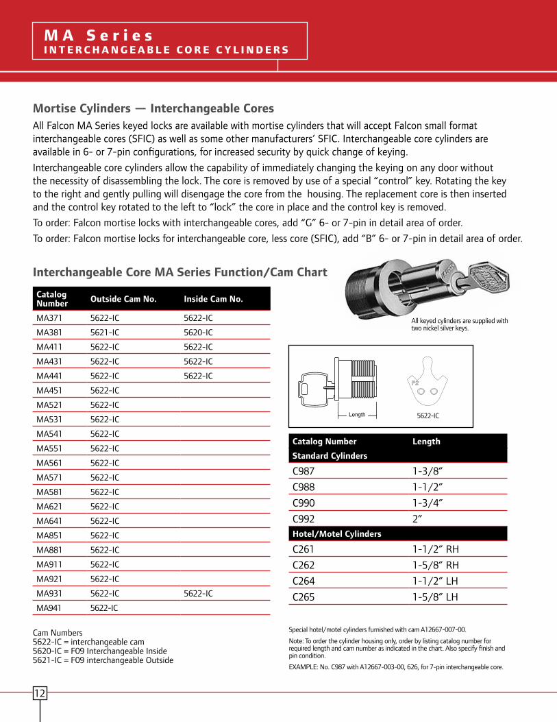
Mortise Cylinders — Interchangeable CoresAll Falcon MA Series keyed locks are available with mortise cylinders that will accept Falcon small format interchangeable cores (SFIC) as well as some other manufacturers’ SFIC. Interchangeable core cylinders are available in 6- or 7-pin configurations, for increased security by quick change of keying.
Interchangeable core cylinders allow the capability of immediately changing the keying on any door without the necessity of disassembling the lock. The core is removed by use of a special “control” key. Rotating the key to the right and gently pulling will disengage the core from the housing. The replacement core is then inserted and the control key rotated to the left to “lock” the core in place and the control key is removed.
To order: Falcon mortise locks with interchangeable cores, add “G” 6- or 7-pin in detail area of order.
To order: Falcon mortise locks for interchangeable core, less core (SFIC), add “B” 6- or 7-pin in detail area of order.
All keyed cylinders are supplied with two nickel silver keys.
5622-ICLength A09894-001-00 A20065-000-00 A09897-000-00
Interchangeable Core MA Series Function/Cam Chart
Catalog Number Outside Cam No. Inside Cam No.
MA371 5622-IC 5622-IC
MA381 5621-IC 5620-IC
MA411 5622-IC 5622-IC
MA431 5622-IC 5622-IC
MA441 5622-IC 5622-IC
MA451 5622-IC
MA521 5622-IC
MA531 5622-IC
MA541 5622-IC
MA551 5622-IC
MA561 5622-IC
MA571 5622-IC
MA581 5622-IC
MA621 5622-IC
MA641 5622-IC
MA851 5622-IC
MA881 5622-IC
MA911 5622-IC
MA921 5622-IC
MA931 5622-IC 5622-IC
MA941 5622-IC
Catalog Number Length
Standard Cylinders
C987 1-3/8”
C988 1-1/2”
C990 1-3/4”
C992 2”Hotel/Motel Cylinders
C261 1-1/2” RH
C262 1-5/8” RH
C264 1-1/2” LH
C265 1-5/8” LH
Special hotel/motel cylinders furnished with cam A12667-007-00.
Note: To order the cylinder housing only, order by listing catalog number for required length and cam number as indicated in the chart. Also specify finish and pin condition.
EXAMPLE: No. C987 with A12667-003-00, 626, for 7-pin interchangeable core.
M A S e r i e sI N T E R C H A N G E A B L E C O R E C Y L I N D E R S
Cam Numbers5622-IC = interchangeable cam5620-IC = F09 Interchangeable Inside5621-IC = F09 interchangeable Outside

13
Mortise Cylinders - StandardOnly the finest materials are used in the manufacture of our cylinders. Modern equipment and gauging ensure consistent, reliable production of our entire line of cylinders. We offer a full and complete line of spacer rings, cylinder guards and spring washers, as well as numerous cams to fulfill the requirements of most applications. Standard mortise cylinders are furnished as 5- or 6-pin as standard. 7-pin cylinders are available. All keyed cylinders are supplied with two nickel silver keys.
Length A09894-001-00 A20065-000-00 A09897-000-00
Standard Core MA Series Function/Cam Chart
Catalog Number Outside Cam No. Inside Cam No.
MA371 5622 5622
MA381 5621 5620
MA411 5622 5622
MA431 5622 5622
MA441 5622 5622
MA451 5622
MA521 5622
MA531 5622
MA541 5622
MA551 5622
MA561 5622
MA571 5622
MA581 5622
MA621 5622
MA641 5622
MA851 5622
MA881 5622
MA911 5622
MA921 5622
MA931 5622 5622
MA941 5622
Catalog Number Length
Standard Cylinders
985 1-1/8”
987 1-3/8”
988 1-1/2”
990 1-3/4”
992 2”Hotel/Motel Cylinders
250 1-1/8” RH 6-pin
251 1-1/4” RH 6-pin
252 1-3/8” LH 6-pin
253 1-3/8” LH 7-pin
Special hotel/motel cylinders, furnished with cam A09894-001-00.
Note: To order cylinder separately, order by listing catalog number for required length and cam number as indicated in chart above. Also, specify finish and number of pins. EXAMPLE: 986 with A09897-000-00, 626, 6-pin
M A S e r i e sS TA N D A R D C Y L I N D E R S
Cam Numbers5622 = standard cam 5620 = F09 standard Inside5621 = F09 standard Outside
5622

Cylinder Guards*Falcon offers two different types of cylinder guards in various thicknesses to work with sectional or escutcheon trim, different door ranges and various cylinder lengths. Our standard cylinder, 985, is 1-1/8” long. The factory will furnish the correct cam(s) and cylinder guard for the function and door thickness specified. The A08790 and A08794 cylinder guards in bar stock brass are available to accommodate different cylinder lengths and door thicknesses as shown.
985 Cylinder withA08790 Cylinder Guard.
985 Cylinder withA08794 Cylinder Guard. A08790 A08794
Escutcheon Trim Ring
Sectional Trim Ring
DoorThickness
Function9851-1/8˝
9861-1/4˝
(c)9871-3/8˝
(c)9881-1/2˝
1-1/2˝ Single cylinder — A08790-000 A08790-001 A08790-002
1-1/2˝ Double cylinder A08790-000 — — —
1-3/4˝ Single cylinder — — A08790-000 A08790-001
1-3/4” Double cylinder — A08790-000 A08790-001 A08790-002
2˝ Single cylinder — — A08790-000 A08790-001
2˝ Double cylinder — — A08790-000 A08790-001
2-1/4˝ Single cylinder — — — A08790-000
2-1/4˝ Double cylinder — — — —
2-1/2˝ Single cylinder — — — —
2-1/2˝ Double cylinder — — — —
DoorThickness
Function9851-1/8˝
9861-1/4˝
(c)9871-3/8˝
(c)9881-1/2˝
1-1/2˝ Single cylinder A08794-001 A08794-002 — —
1-1/2˝ Double cylinder A08794-002 A08794-003 — —
1-3/4˝ Single cylinder A08794-000 A08794-001 A08794-002 —
1-3/4” Double cylinder A08794-001 A08794-002 A08794-003 —
2˝ Single cylinder — A08794-000 A08794-001 A08794-002
2˝ Double cylinder A08794-000 A08794-001 A08794-002 A08794-003
2-1/4˝ Single cylinder — — A08794-000 A08794-001
2-1/4˝ Double cylinder — A08794-000 A08794-001 A08794-002
2-1/2˝ Single cylinder — — — A08794-000
2-1/2˝ Double cylinder — — A08794-000 A08794-001
Specify part number and finish when ordering. (e.g. A08790-000-626)** Single cylinder functions.
M A S e r i e sC Y L I N D E R G UA R D S
14

M A S e r i e sF u n c t i o n s ( c o n t i n u e d )M A S e r i e sC Y L I N D E R G UA R D S
Cylinder Guards Continued
15
Rim Cylinder Tailpieces
Dim. B Part No.
3/32” 9/32” A08790-000
7/32” 13/32˝ A08790-001
11/32˝ 17/32˝ A08790-002
15/32˝ 21/32˝ A08790-003
43/64” 55/64” A08790-004
Dim. A
Dim. B Part No.
3/32” 9/32” A08794-000
7/32” 13/32˝ A08794-001
11/32˝ 17/32˝ A08794-002
15/32˝ 21/32˝ A08794-003
Dim. A
Dim. B Part No.
1/8˝ — 008876-000
3/16˝ — 008876-005
1/4˝ — 008876-001
3/8˝ — 008876-002
1/2˝ — 008876-003
5/8˝ — 008876-004
Dim. A
Dim. A Dim. B Part No.
3/32” 7/32” 11/32” 15/32” 43/64”
9/32” 13/32” 17/32” 21/32” 55/64”
A08790-000 A08790-001 A08790-002 A08790-003 A08790-004
3/32” 7/32” 11/32” 15/32”
9/32” 13/32” 17/32” 21/32”
A08794-000 A08794-001 A08794-002 A08794-003
1/8” 3/16” 1/4” 3/8” 1/2” 5/8”
— — — — — —
008876-000 008876-005 008876-001 008876-002 008876-003 008876-004
AB
AB
A
Wave washer included.
To order separately, specify 008789-001-60
008862-000
For all rim cylinders and cam locks.
(e.g. A08790-000-626)
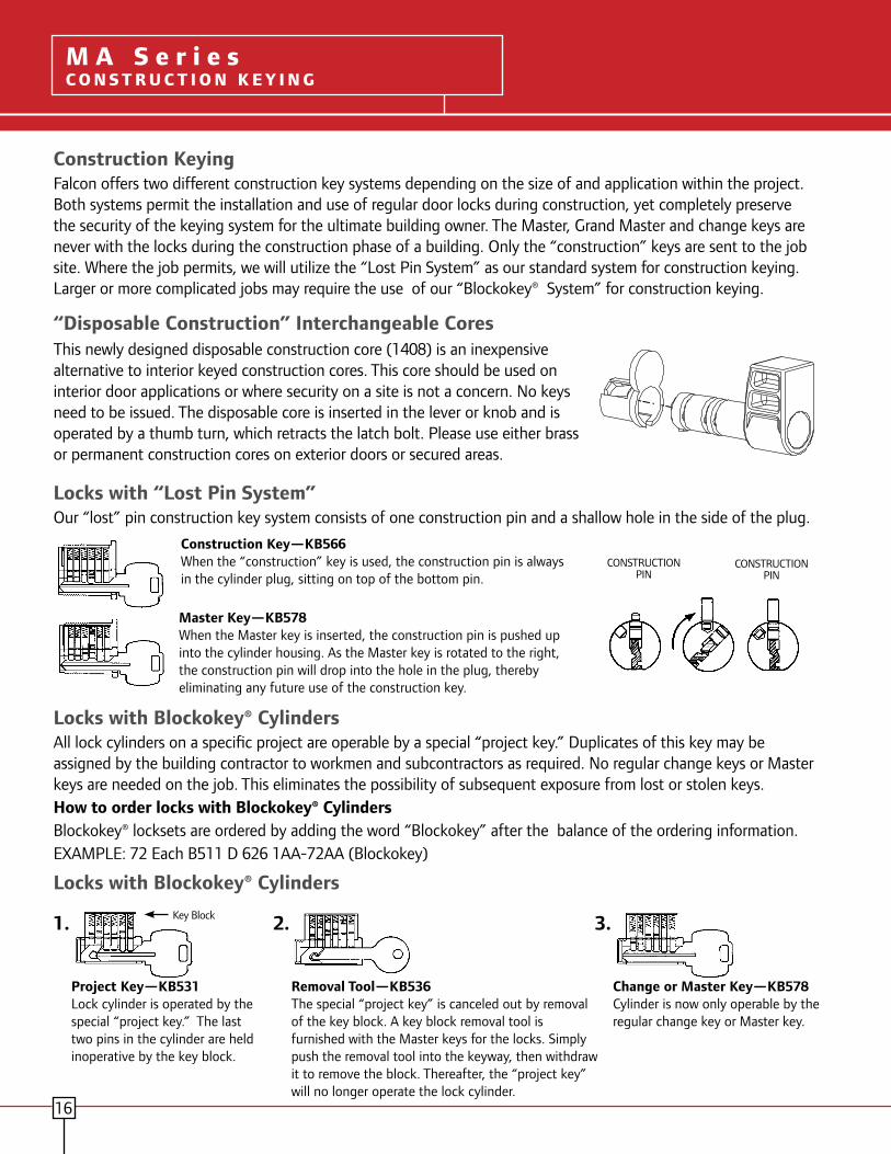
M A S e r i e sF u n c t i o n s ( c o n t i n u e d )M A S e r i e sC O N S T R U C T I O N K E Y I N G
16
Construction KeyingFalcon offers two different construction key systems depending on the size of and application within the project. Both systems permit the installation and use of regular door locks during construction, yet completely preserve the security of the keying system for the ultimate building owner. The Master, Grand Master and change keys are never with the locks during the construction phase of a building. Only the “construction” keys are sent to the job site. Where the job permits, we will utilize the “Lost Pin System” as our standard system for construction keying. Larger or more complicated jobs may require the use of our “Blockokey® System” for construction keying.
“Disposable Construction” Interchangeable CoresThis newly designed disposable construction core (1408) is an inexpensive alternative to interior keyed construction cores. This core should be used on interior door applications or where security on a site is not a concern. No keys need to be issued. The disposable core is inserted in the lever or knob and is operated by a thumb turn, which retracts the latch bolt. Please use either brass or permanent construction cores on exterior doors or secured areas.
Locks with “Lost Pin System”Our “lost” pin construction key system consists of one construction pin and a shallow hole in the side of the plug.
Construction Key—KB566When the “construction” key is used, the construction pin is always in the cylinder plug, sitting on top of the bottom pin.
Master Key—KB578When the Master key is inserted, the construction pin is pushed up into the cylinder housing. As the Master key is rotated to the right, the construction pin will drop into the hole in the plug, thereby eliminating any future use of the construction key.
CONSTRUCTION PIN
CONSTRUCTION PIN
Locks with Blockokey® CylindersAll lock cylinders on a specific project are operable by a special “project key.” Duplicates of this key may be assigned by the building contractor to workmen and subcontractors as required. No regular change keys or Master keys are needed on the job. This eliminates the possibility of subsequent exposure from lost or stolen keys.How to order locks with Blockokey® CylindersBlockokey® locksets are ordered by adding the word “Blockokey” after the balance of the ordering information. EXAMPLE: 72 Each B511 D 626 1AA-72AA (Blockokey)
Locks with Blockokey® Cylinders
1. Key Block
Project Key—KB531Lock cylinder is operated by the special “project key.” The last two pins in the cylinder are held inoperative by the key block.
2.
Removal Tool—KB536The special “project key” is canceled out by removal of the key block. A key block removal tool is furnished with the Master keys for the locks. Simply push the removal tool into the keyway, then withdraw it to remove the block. Thereafter, the “project key” will no longer operate the lock cylinder.
3.
Change or Master Key—KB578Cylinder is now only operable by the regular change key or Master key.
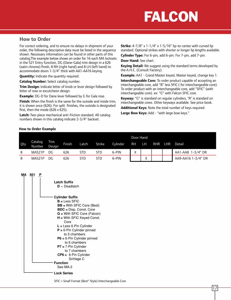
M A S e r i e sC o n v e r s i o n C h a r t
For correct ordering, and to ensure no delays in shipment of your order, the following descriptive data must be listed in the sequence shown. Necessary information can be found in other parts of this catalog.The example below shows an order for 16 each MA locksets in the 521 Entry function, DG (Dane-Gala) trim design in a 626 (satin chrome) finish, 8 RH (right hand) and 8 LH (left hand) to accommodate doors 1-3/4” thick with AA1-AA16 keying.
Quantity: Indicate the quantity required.
Catalog Number: Select catalog number.
Trim Design: Indicate letter of knob or lever design followed by letter of rose or escutcheon design.
Example: DG-D for Dane lever followed by G for Gala rose.
Finish: When the finish is the same for the outside and inside trim, it is shown once (626). For split finishes, the outside is designated first, then the inside (626 x 625).
Latch: Two-piece mechanical anti-friction standard. All catalog numbers shown in this catalog indicate 2-3/4” backset.
Strike: 4-7/8” x 1-1/4” x 1-5/16” lip-to-center with curved lip standard. Optional strikes with shorter or longer lip lengths available.
Cylinder Type: For 6-pin, add 6-pin. For 7-pin, add 7-pin.
Door Hand: See chart .
Keying Detail: We suggest using the standard terms developed by the A.H.C. (Consult Factory).
Example: AA1 - Grand Master keyed, Master keyed, change key 1.
Interchangeable Core: To order product capable of accepting an interchangeable core, add “B” less SFIC ( for interchangeable core). To order product with an interchangeable core, add “SFIC” (with interchangeable core). ex: “G” with Falcon SFIC core.
Keyway: “G” is standard on regular cylinders, “A” is standard on interchangeable cores. Other keyways available. See price book.
Additional Keys: Note the total number of keys required.
Large Bow Keys: Add - “with large bow keys.”
How to Order
How to Order Example
Qty.Catalog Number
Trim Design
Finish Latch Strike Cylinder RH LH RHR LHR Detail
8 MA521P DG 626 STD STD 6-PIN X AA1-AA8 1-3/4” DR
8 MA521P DG 626 STD STD 6-PIN X AA9-AA16 1-3/4” DR
M A S e r i e sI n t e r c h a n g e a b l e C o r e C y l i n d e r s
Door Hand
17
Product IdentificationMA 501 P
Latch Suffix D = Deadlatch
Cylinder Suffix B = Less SFIC BB = With SFIC Core (Best) BDC = Disp. Const. Core G = With SFIC Core (Falcon) H = With SFIC Keyed Const.
Core L = Less 6-Pin Cylinder P = 6-Pin Cylinder pinned
to 5 chambers P6 = 6-Pin Cylinder pinned
to 6 chambers P7 = 7-Pin Cylinder
to 7 chambers CP6 = 6-Pin Cylinder
Schlage C Function See MA-2
Lock Series
SFIC = Small Format (Best® Style) Interchangeable CoreSFIC = Small Format (Best® Style) Interchangeable Core

M A S e r i e sF u n c t i o n s ( c o n t i n u e d )M A S e r i e sF I N I S H E S
FinishesFalcon offers several finish choices to compliment the design elements of most any project. Falcon applies the best available protective plating or coating to the surface of our products to minimize the exposure to weather, pollution, perspiration, extremes of climate, frequency of us and other factors. Please
consult with us if your building is subjected to chemical or corrosive conditions, as some finishes would not be recommended for these areas. Falcon recommends chrome plated or stainless steel finishes for high corrosive environments.
Trim Finishes Chart
Available Finishes
Description ANSI No. Available on
Bright Brass 605 All Trim
Satin Brass 606 All Trim
Satin Bronze Oil Rubbed
613 All Trim
Bright Chrome 625 All Trim
Satin Chrome 626 All Trim
Satin Stainless Steel 630 All Trim
How to Determine the Hand of a Door
605Bright Brass
606Satin Brass
613Oil Rubbed
Bronze
625Bright Chrome
626Satin Chrome
630Satin Stainless
Steel
18

Ingersoll Rand’s Security Technologies Sector is a leading global provider of products and services that make environments
safe, secure and productive. The sector’s market-leading products include electronic and biometric access-control systems;
time-and-attendance and personnel scheduling systems; mechanical locks; portable security; door closers, exit devices,
architectural hardware, and steel doors and frames; and other technologies and services for global security markets.
800-266-4456 www.falcon.ingersollrand.com www.ingersollrand.com
©2009 Ingersoll Rand Company FA-5164 Rev. 11-09
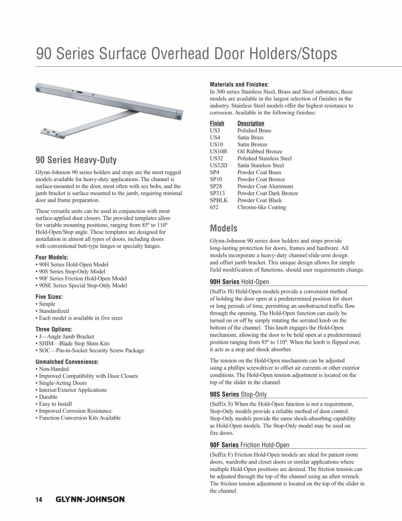
14
90 Series Surface Overhead Door Holders/Stops
90 Series Heavy-DutyGlynn-Johnson 90 series holders and stops are the most ruggedmodels available for heavy-duty applications. The channel is surface-mounted to the door, most often with sex bolts, and thejamb bracket is surface mounted to the jamb, requiring minimaldoor and frame preparation.
These versatile units can be used in conjunction with most surface-applied door closers. The provided templates allow for variable mounting positions, ranging from 85º to 110º Hold-Open/Stop angle. These templates are designed for installation in almost all types of doors, including doors with conventional butt-type hinges or specialty hinges.
Four Models:• 90H Series Hold-Open Model• 90S Series Stop-Only Model• 90F Series Friction Hold-Open Model• 90SE Series Special Stop-Only Model
Five Sizes:• Simple• Standardized• Each model is available in five sizes
Three Options:• J—Angle Jamb Bracket• SHIM—Blade Stop Shim Kits• SOC—Pin-in-Socket Security Screw Package
Unmatched Convenience:• Non-Handed• Improved Compatibility with Door Closers• Single-Acting Doors• Interior/Exterior Applications• Durable• Easy to Install• Improved Corrosion Resistance• Function Conversion Kits Available
Materials and Finishes:In 300 series Stainless Steel, Brass and Steel substrates, these models are available in the largest selection of finishes in the industry. Stainless Steel models offer the highest resistance to corrosion. Available in the following finishes:
Finish DescriptionUS3 Polished BrassUS4 Satin BrassUS10 Satin BronzeUS10B Oil Rubbed BronzeUS32 Polished Stainless SteelUS32D Satin Stainless SteelSP4 Powder Coat BrassSP10 Powder Coat BronzeSP28 Powder Coat AluminumSP313 Powder Coat Dark BronzeSPBLK Powder Coat Black652 Chrome-like Coating
ModelsGlynn-Johnson 90 series door holders and stops provide long-lasting protection for doors, frames and hardware. All models incorporate a heavy-duty channel/slide-arm design and offset jamb bracket. This unique design allows for simplefield modification of functions, should user requirements change.
90H Series Hold-Open (Suffix H) Hold-Open models provide a convenient method of holding the door open at a predetermined position for short or long periods of time, permitting an unobstructed traffic flowthrough the opening. The Hold-Open function can easily be turned on or off by simply rotating the serrated knob on the bottom of the channel. This knob engages the Hold-Open mechanism, allowing the door to be held open at a predeterminedposition ranging from 85º to 110º. When the knob is flipped over, it acts as a stop and shock absorber.
The tension on the Hold-Open mechanism can be adjusted using a phillips screwdriver to offset air currents or other exteriorconditions. The Hold-Open tension adjustment is located on the top of the slider in the channel.
90S Series Stop-Only (Suffix S) When the Hold-Open function is not a requirement,Stop-Only models provide a reliable method of door control. Stop-Only models provide the same shock-absorbing capability as Hold-Open models. The Stop-Only model may be used on fire doors.
90F Series Friction Hold-Open (Suffix F) Friction Hold-Open models are ideal for patient roomdoors, wardrobe and closet doors or similar applications where multiple Hold-Open positions are desired. The friction tension canbe adjusted through the top of the channel using an allen wrench.The friction tension adjustment is located on the top of the slider inthe channel.

15
90SE Series Special Stop-Only (Suffix SE) When Stop-Only models are used in conjunction with single-point, Hold-Only electronic door closers, the Stop-Only function may be ordered without the shock-absorbing mechanism. Used as an auxiliary stop, these models prolong the life of the closer. The stop location is adjusted using an allenwrench on the stop block located in the channel.
Note: Caution should be taken when using this option in other applications, asthe elimination of the shock-absorbing spring can put added stress on the doorand frame.
Application InformationUL ClassificationThe 90 series Stop-Only models are classified by UnderwritersLaboratories (UL) as Miscellaneous Fire Door Accessories. Thisclassification applies to use on either Hollow Metal Fire Doors orWood Fire Doors. These units may be used on doors of any rating.As a reminder, the Miscellaneous Fire Door Accessories (GVUX)section is defined by UL as: “Miscellaneous fire door accessoriesare intended in the individual Listings. The accessories have beeninvestigated to determine that when installed in accordance with the manufacturer’s instructions, the accessories do not adverselyaffect the fire rating of the fire door and/or fire door frames.”
Dead-Stop Templating:Dead-stop templating is recommended for applications where awall or similar obstruction is placed at an opening angle of 110º or less (i.e., doors that open back-to-back). Dead-stop templatingcan be applied to Hold-Open, Stop-Only and Friction models. The Dead-Stop position is the point at which the shock-absorbing spring is fully compressed. Therefore, when Dead-Stop Templatingis used, the initial degree of opening will be 5º to 7º less than theDead-Stop opening.
Example: If the holder is templated to a 100º Dead Stop, the door will holdopen at an angle between 93º and 95º but no further than 100º
Note: Do not use dead-stop templating on the 90SE Series since there is noshock-absorbing spring.
Environmental Considerations:Environmental factors should always be considered when specifying overhead holders and stops. Doors that are positioned on a building’s exterior or subject to corrosive conditions should be equipped with a holder constructed primarily of stainless steel or brass materials. For interior applications, steel is acceptable,though brass substrates generally provide a more attractive architectural-grade finish.
Function Conversion Kits• FK90H—Converts a 90F or a 90S unit into a 90H unit.
To order specify FK90H.• FK90F—Converts a 90H or a 90S unit into a 90F unit.
To order specify FK90F.• FK90SE—Converts a 90H, 90F or a 90S unit into a 90SE unit. To
order specify FK90SE–Finish.• No kit is needed to convert a 90H or 90F unit into a 90S unit.
OptionsSuffix J (Angle Jamb Bracket):An angle jamb bracket is available for converting standard modelsto hinge-side or flush transom mounting. The angle jamb bracketaffixes to the standard jamb bracket. If ordered with the unit addsuffix J. If needed separately order 90J by finish needed.
Suffix SOC (Pin-in-Socket Security Screws):A screw package with pin-in-socket screws for mounting the doorbracket and the jamb bracket is provided instead of the standardscrew package.
Suffix SHIM (Blade Stop Shims):Shim kits are available in 3 sizes90 SHIM1 is a 1/4" Shim Kit90 SHIM2 is a 1/2" Shim Kit90 SHIM3 is a 3/4" Shim Kit
If ordered with overhead, add suffix SHIM (1, 2 or 3). If needed separately order 90 SHIM (1, 2 or 3)–Finish.
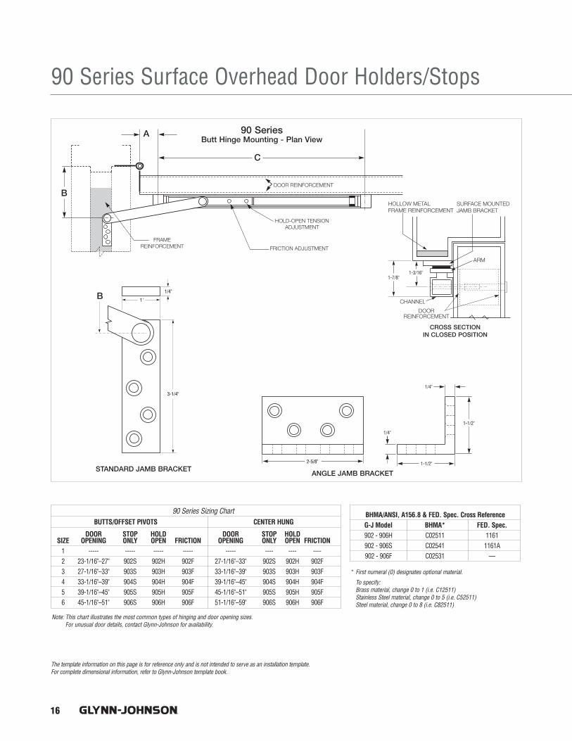
16
90 Series Surface Overhead Door Holders/Stops
The template information on this page is for reference only and is not intended to serve as an installation template. For complete dimensional information, refer to Glynn-Johnson template book.
1'
1/4"
3-1/4"
2-5/8"
1/4"
1-1/2"
1-1/2"
1/4"
1-7/8"1-3/16"
BUTTS/OFFSET PIVOTS CENTER HUNG
DOOR STOP HOLD DOOR STOP HOLDSIZE OPENING ONLY OPEN FRICTION OPENING ONLY OPEN FRICTION
1 ----- ----- ----- ----- ----- ---- ---- ----2 23-1/16"–27" 902S 902H 902F 27-1/16"–33" 902S 902H 902F3 27-1/16"–33" 903S 903H 903F 33-1/16"–39" 903S 903H 903F 4 33-1/16"–39" 904S 904H 904F 39-1/16"–45" 904S 904H 904F5 39-1/16"–45" 905S 905H 905F 45-1/16"–51" 905S 905H 905F6 45-1/16"–51" 906S 906H 906F 51-1/16"–59" 906S 906H 906F
90 Series Sizing Chart
* First numeral (0) designates optional material.
To specify: Brass material, change 0 to 1 (i.e. C12511)Stainless Steel material, change 0 to 5 (i.e. C52511)Steel material, change 0 to 8 (i.e. C82511)
Note: This chart illustrates the most common types of hinging and door opening sizes. For unusual door details, contact Glynn-Johnson for availability.
BHMA/ANSI, A156.8 & FED. Spec. Cross ReferenceG-J Model BHMA* FED. Spec.902 - 906H C02511 1161902 - 906S C02541 1161A902 - 906F C02531 —
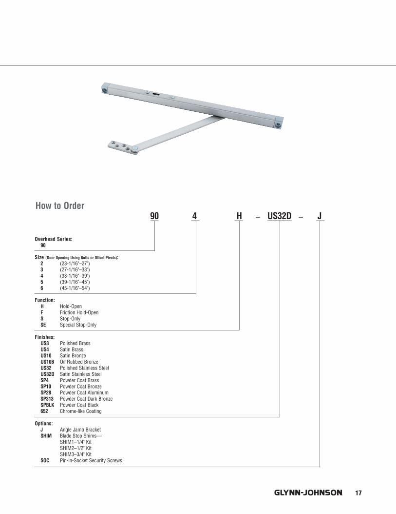
17
How to Order
Overhead Series:90
Size (Door Opening Using Butts or Offset Pivots):2 (23-1/16"–27")3 (27-1/16"–33")4 (33-1/16"–39")5 (39-1/16"–45")6 (45-1/16"–54")
Function:H Hold-OpenF Friction Hold-OpenS Stop-OnlySE Special Stop-Only
Finishes:US3 Polished BrassUS4 Satin BrassUS10 Satin BronzeUS10B Oil Rubbed BronzeUS32 Polished Stainless SteelUS32D Satin Stainless SteelSP4 Powder Coat BrassSP10 Powder Coat BronzeSP28 Powder Coat AluminumSP313 Powder Coat Dark BronzeSPBLK Powder Coat Black652 Chrome-like Coating
Options:J Angle Jamb BracketSHIM Blade Stop Shims—
SHIM1–1/4" KitSHIM2–1/2" KitSHIM3–3/4" Kit
SOC Pin-in-Socket Security Screws
__ __ __ – ______ – __90 4 H US32D J

26
450 Series Surface Overhead Door Holders/Stops
Materials and Finishes:In Brass, 300 series stainless steel or steel, these models offer the broadest range of finishes in the industry to complement any design. Brass and Stainless Steel offer the highest resistance to corrosion, while all these base materials are suitable for normal interior use.
Finish DescriptionUS3 Polished BrassUS4 Satin BrassUS10 Satin BronzeUS10B Oil Rubbed BronzeUS32 Polished Stainless SteelUS32D Satin Stainless SteelSP4 Powder Coast BrassSP10 Powder Coat BronzeSP28 Powder Coat AluminumSP313 Powder Coat Dark BronzeSPBLK Powder Coat Black652 Chrome-like Coating
ModelsGlynn-Johnson 450 series holders and stops are designed for medium to light-duty applications. They’re ideal for openings thatare subject to normal activity, providing protection for the door,frame, hinges and surrounding walls or obstructions.
Designed for improved compatibility with most door closers, allmodels incorporate popular channel/slide arm design and offsetjamb brackets. The improved design makes it easier to change functions in the field, should user requirements change.
450H Series Hold-Open (Suffix H) These models conveniently hold doors open at a predetermined position, permitting unobstructed traffic flow.
These models feature an adjustable automatic Hold-Open that isactivated when the door is opened to a preset angle. The Hold-Opentension can be adjusted using an allen wrench through the end ofthe slider located in the channel at the top of the door. Each meetsthe 250,000 test cycles required for Grade 1 classification.
450S Series Stop-Only (Suffix S) When the Hold-Open function is not required, the Stop-Only function provides the same effective door control without keeping the door held open. The Stop-Only model may be used on fire doors.
450F Series Friction Hold-Open (Suffix F) Friction Hold-Open models provide an alternative holding method ideal for patient room doors, wardrobe or closet doors, or similar applications where multiple Hold-Openpositions are desired. The friction tension can be adjusted using an allen wrench on the slider located in the channel at the top of the door.
450 Series Medium-DutyGlynn-Johnson provides the most complete line of overhead holders and stops, offering solutions for the most demanding door control problems. These surface-mounted holders and stops offer the widest variety of functions, materials and finishes to fit all medium- to light-duty applications.
Glynn-Johnson 450 series holders and stops provide reliable andversatile surface-mounted overhead door control for all medium to light-duty applications. The visible components are available in a wide variety of architectural finishes to complement any design.The 450 series holders and stops are designed for installation in virtually all types of doors and frames including doors with conventional butt hinges, offset pivots, continuous hinges, swingclear hinges and many other specialty hinges. The templates provided allow for variable mounting positions, ranging from 85° - 110° of opening.
Four Models:• 450H Series Hold-Open Model• 450S Series Stop-Only Model• 450F Series Friction Hold-Open Model• 450SE Series Special Stop-Only Model
Five Sizes:• Simple• Standardized• Each model is available in five sizes
Three Options:• J—Angle Jamb Bracket• SHIM—Blade Stop Shim Kit• SOC—Pin-in-Socket Security Screw Package
Unmatched Convenience:• Non-Handed• Improved Compatibility with Door Closers• Improved Jamb Bracket Design• Single Acting Doors• Interior Applications• Durable• Easy to Install• Improved Corrosion Resistance
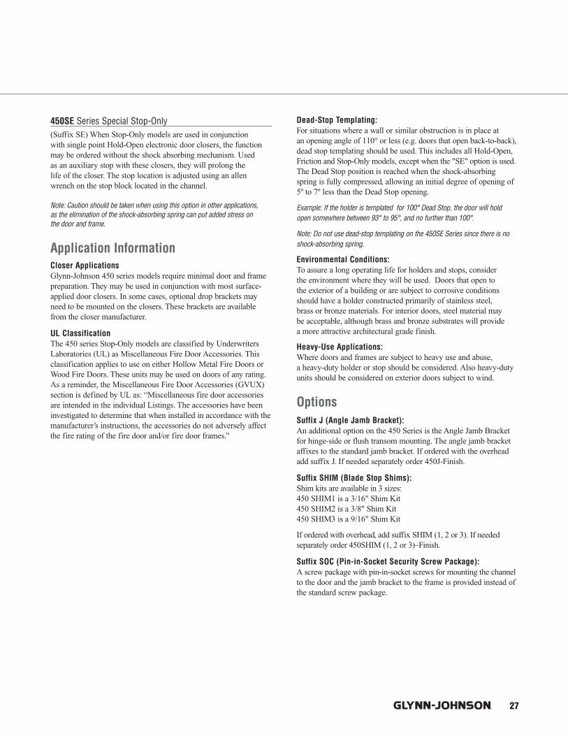
27
450SE Series Special Stop-Only (Suffix SE) When Stop-Only models are used in conjunction with single point Hold-Open electronic door closers, the functionmay be ordered without the shock absorbing mechanism. Used as an auxiliary stop with these closers, they will prolong the life of the closer. The stop location is adjusted using an allenwrench on the stop block located in the channel.
Note: Caution should be taken when using this option in other applications, as the elimination of the shock-absorbing spring can put added stress on the door and frame.
Application InformationCloser ApplicationsGlynn-Johnson 450 series models require minimal door and framepreparation. They may be used in conjunction with most surface-applied door closers. In some cases, optional drop brackets mayneed to be mounted on the closers. These brackets are availablefrom the closer manufacturer.
UL ClassificationThe 450 series Stop-Only models are classified by UnderwritersLaboratories (UL) as Miscellaneous Fire Door Accessories. Thisclassification applies to use on either Hollow Metal Fire Doors orWood Fire Doors. These units may be used on doors of any rating.As a reminder, the Miscellaneous Fire Door Accessories (GVUX)section is defined by UL as: “Miscellaneous fire door accessoriesare intended in the individual Listings. The accessories have beeninvestigated to determine that when installed in accordance with themanufacturer’s instructions, the accessories do not adversely affectthe fire rating of the fire door and/or fire door frames.”
Dead-Stop Templating: For situations where a wall or similar obstruction is in place at an opening angle of 110° or less (e.g. doors that open back-to-back),dead stop templating should be used. This includes all Hold-Open,Friction and Stop-Only models, except when the "SE" option is used. The Dead Stop position is reached when the shock-absorbingspring is fully compressed, allowing an initial degree of opening of5º to 7º less than the Dead Stop opening.
Example: If the holder is templated for 100° Dead Stop, the door will holdopen somewhere between 93° to 95°, and no further than 100°.
Note: Do not use dead-stop templating on the 450SE Series since there is noshock-absorbing spring.
Environmental Conditions: To assure a long operating life for holders and stops, consider the environment where they will be used. Doors that open to the exterior of a building or are subject to corrosive conditionsshould have a holder constructed primarily of stainless steel, brass or bronze materials. For interior doors, steel material may be acceptable, although brass and bronze substrates will provide a more attractive architectural grade finish.
Heavy-Use Applications: Where doors and frames are subject to heavy use and abuse, a heavy-duty holder or stop should be considered. Also heavy-dutyunits should be considered on exterior doors subject to wind.
OptionsSuffix J (Angle Jamb Bracket):An additional option on the 450 Series is the Angle Jamb Bracketfor hinge-side or flush transom mounting. The angle jamb bracketaffixes to the standard jamb bracket. If ordered with the overheadadd suffix J. If needed separately order 450J-Finish.
Suffix SHIM (Blade Stop Shims):Shim kits are available in 3 sizes:450 SHIM1 is a 3/16" Shim Kit450 SHIM2 is a 3/8" Shim Kit450 SHIM3 is a 9/16" Shim Kit
If ordered with overhead, add suffix SHIM (1, 2 or 3). If needed separately order 450SHIM (1, 2 or 3)–Finish.
Suffix SOC (Pin-in-Socket Security Screw Package):A screw package with pin-in-socket screws for mounting the channelto the door and the jamb bracket to the frame is provided instead ofthe standard screw package.

28
450 Series Surface Overhead Door Holders/Stops
The template information on this page is for reference only and is not intended to serve as an installation template. For complete dimensional information, refer to Glynn-Johnson template book.
1-5/16"7/8"
3/16"
3/16"1-1/4"
1-1/4"2-1/4"
2-7/8"
3/16"
3/4"
BUTTS/OFFSET PIVOTS CENTER HUNG
DOOR STOP HOLD DOOR STOP HOLDSIZE OPENING ONLY OPEN FRICTION OPENING ONLY OPEN FRICTION
1 18"–23" 451S 451H 451F 23-1/16"–27" 451S 451H 451F2 23-1/16"–27" 452S 452H 452F 27-1/16"–33" 452S 452H 452F3 27-1/16"–33" 453S 453H 453F 33-1/16"–39" 453S 453H 453F 4 33-1/16"–39" 454S 454H 454F 39-1/16"–45" 454S 454H 454F5 39-1/16"–45" 455S 455H 455F 45-1/16"–51" 455S 455H 455F
450 Series Sizing Chart
* First numeral (0) designates optional material.
To specify: Brass/bronze material, change 0 to 1 (e.e. C15511)Stainless Steel Material, change 0 to 5 (i.e. C55511)Steel material, change 0 to 8 (i.e. C85511)Note: This chart illustrates the most common types of hinging and door opening sizes.
For unusual door details, contact Glynn-Johnson for availability.
BHMA/ANSI, A156.8 & FED. Spec. Cross ReferenceG-J Model BHMA* FED. Spec.451-455 H C05511 1166451-455 S C05541 1166A451-455 F C05531 1164

Overhead Series:45
Size (Door Opening Using Butts or Offset Pivots):1 (18"–23")2 (23-1/16"–27")3 (27-1/16" –33")4 (33-1/16"–39")5 (39-1/16"–45")
Function:H Hold-OpenF Friction Hold-OpenS Stop-OnlySE Special Stop-Only
Finishes:US3 Polished BrassUS4 Satin BrassUS10 Satin BronzeUS10B Oil Rubbed BronzeUS32 Polished Stainless SteelUS32D Satin Stainless SteelSP4 Powder Coat BrassSP10 Powder Coat BronzeSP28 Powder Coat AluminumSP313 Powder Coat Dark BronzeSPBLK Powder Coat Black652 Chrome-like Coating
Options: J Angle Jamb BracketSHIM Blade Stop Shims—
SHIM1–3/16" KitSHIM2–3/8" KitSHIM3–9/16" Kit
SOC Pin-in-Socket Security Screws
29
How to Order45 1 H US32D J___ __ __ – ______ – __

1
Architectural Door Trim
8103EZ Door Pull - Large 2-1/2" Clearance for the Physically ImpairedProd No. Proj. (A) Center to Center (B) Overall Length (C)
8103EZ 3-1/2" 8" 9"8103EZ 3-1/2" 10" 11"8103EZ 3-1/2" 12" 13"
How to Order8103EZ - - -
Size:8 for 8"0 for 10"2 for 12"
FinishesUS3, US4, US10, US10B, US26, US26D, US28, US32, US32D
Mounting Type:Blank StandardL Surface Concealed Two-Anchor M Back-To-Back with Spanner CollarN Back-to-Back Two-AnchorO Decorative Blind Thru-Bolt
8190 90° Offset Door PullProd No. Proj. (A) Center to Center (B) Overall Length (C)
8190 3-1/4" 8" 9"8190 3-1/4" 10" 11"8190 3-1/4" 12" 13"8190 3-1/4" 18" 19"
How to Order8190 - - -
Size:8 for 8"0 for 10"2 for 12"18 for 18"
FinishesUS3, US4, US10, US10BUS26, US26D, US32, US32D
Mounting Type:Blank StandardL Surface Concealed Two-Anchor M Back-To-Back with Spanner CollarN Back-to-Back Two-Anchor O Decorative Blind Thru-Bolt

4
Mounting
Type NS-Standard Push/Pull MountingType N & Standard
Pushbar to Pull- (1) 1/4-20 X 3"steel countersunk trim head machine screws with (2) set screws.- (1) steel screw sleeve, zinc plated.
Free End Pushbar & Pull- (2) 1/4-20 X 2-1/4" brass, oval head mach screws; plated to match.- (2) No. 14 countersunk washers; plated to match.
Type NO Push/Pull MountingType N & Type O
Pushbar to Pull- (1) 1/4-20 X 3"steel countersunk trim head machine screws with (2) set screws.- (1) steel screw sleeve, zinc plated.
Free End Pushbar & Pull- (2) 1/4-20 X 2-1/4" blind thru-bolts; plated to match.
NOTES:* All mounting hardware is for standard 1-3/4" door.* Consult Customer Service if other than standard.
Architectural Door Trim

C2
Architectural Door Trim
How to Order8105 - ___ - ___ - ___
Size: 6 for 6"8 for 8"0 for 10"
Finishes: US3, US4, US5, US10, US10B, US15, US15A, US26, US26D, US28, US32, US32D
Mounting Type: Blank StandardF Concealed wood door w/push plate (special)
8105 Door Pull
Prod. Proj. Center to Center Overall LengthNo. “A” “B” “C”
8105-6 2" 6" 6-1/2"8105-8 2" 8" 8-1/2"8105-0 2" 10" 10-1/2"
8100 Series Door Pulls• Made from the finest architectural brass, stainless steel
and aluminum available.• Each pull is carefully machined, polished and inspected before
being individually wrapped and packaged.
• Door pulls are packed with standard type fasteners for 1-3/4"doors. For special mounting methods other than standard, see pages C11 - C13.
• For sizes and finishes not listed in this catalog, contact ourCustomer Service Department for availability.
8103EZ Door Pull - Large 2-1/2" Clearance for the Physically ImpairedProd. Proj. Center to Center Overall LengthNo. “A” “B” “C”
8103EZ 3-1/2" 8" 9"8103EZ 3-1/2" 10" 11"8103EZ 3-1/2" 12" 13"
Size:8 for 8"0 for 10"2 for 12"
FinishesUS3, US4, US10, US10B, US15, US15A US26, US26D, US28, US32, US32D
Mounting Type:Blank StandardL Surface Concealed Two-Anchor M Back-To-Back with Spanner Collar. Furnished in Pairs. (PR)M1 Single (SGL) Pull. Back-to-back With
Spanner Collar. RH Thread.M2 Single (SGL) Pull. Back-to-back With
Spanner Collar. LH Thread.N Back-to-Back Two-Anchor. Furnished in Pairs. (PR)N2 Single (SGL) Pull, Back-to-Back Two Anchor.O Decorative Blind Thru-Bolt
How to Order8103EZ - ___ - ___ - ___
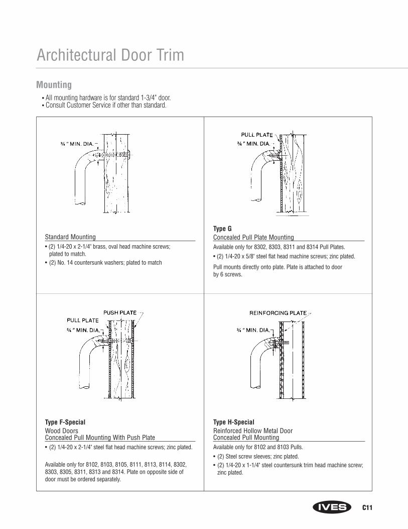
C11
Architectural Door Trim
Type F-SpecialWood DoorsConcealed Pull Mounting With Push Plate• (2) 1/4-20 x 2-1/4" steel flat head machine screws; zinc plated.
Available only for 8102, 8103, 8105, 8111, 8113, 8114, 8302, 8303, 8305, 8311, 8313 and 8314. Plate on opposite side of door must be ordered separately.
Standard Mounting• (2) 1/4-20 x 2-1/4" brass, oval head machine screws;
plated to match.• (2) No. 14 countersunk washers; plated to match
Type GConcealed Pull Plate MountingAvailable only for 8302, 8303, 8311 and 8314 Pull Plates.
• (2) 1/4-20 x 5/8" steel flat head machine screws; zinc plated.
Pull mounts directly onto plate. Plate is attached to door by 6 screws.
Type H-Special Reinforced Hollow Metal Door Concealed Pull MountingAvailable only for 8102 and 8103 Pulls.
• (2) Steel screw sleeves; zinc plated.• (2) 1/4-20 x 1-1/4" steel countersunk trim head machine screw;
zinc plated.
Mounting• All mounting hardware is for standard 1-3/4" door.• Consult Customer Service if other than standard.

A1
Automatic Flush Bolts - Metal Doors
FB30 Series for Metal Doors• Fully Automatic—inactive door is latched when active door closes,
bolts retract when active door is opened.• Low Actuation Forces—Top Bolt Has No Spring Tension.• UL Listed for Fire Doors.• Fits standard ANSI A115.4 Door Frame Preparations.• Non-handed.• Models with Auxiliary Fire Latch eliminates the bottom bolt
and is UL Listed for Fire Doors.• Finishes: US3, US4, US10, US10B, US32, US32D.
• Finished Cover Plates permit finish changes in stock or at job site.• Bolts have 3/4" throw with a 7/8" vertical adjustment.• Standard Rod Length is 12", which is measured from the center
of the flush bolt body to the bolt tip. • Meets ANSI A156.3 Type 25.• Optional Dust Proof Strikes—DP1 or DP2, prevents
dirt build-up assuring full engagement of bottom bolt.• Optional rod lengths available for top bolt for non-fire rated
openings—18", 24", 36" and 48".
FB31P PairTop and Bottom Bolts
Both bolts are non-handed, but are notidentical. The top bolthas no spring tension,resulting in lower actuation force with asmoother operation.
• UL Listed 3 hours on8'0" x 10'0" Opening
FB32Top Bolt with Auxiliary Fire Latch
FB32 combinationincludes FB31T Top Boltwith auxiliary fire latch.Provides a fire-listedapplication without abottom bolt— meaningno floor prep and strike.The auxiliary fire latch,mounted in the door edge,releases under extreme-ly high temperatures tokeep the doors in alignment during a fire.
• UL Listed 3 hours on8'0" x 8'0" Opening
FB33Top Bolt with Auxiliary Fire Latch and Retrofit Plate
FB33 used to updateexisting flush boltinstallations with auxiliary fire latch eliminating bottom boltand floor strike. FB33consists of FB31T TopBolt, auxiliary Fire Latchand Filler plate to coverexisting cutout whenbottom bolt is removed.
• UL Listed 3 hours on8'0" x 8'0" Opening
FB31TTop Bolt Only
FB31BBottom Bolt Only
Dimensions:Body Size: 1" Wide x 6-3/4" Long x 2" DeepGuide Size: 1" Wide x 1-27/32" Long x 27/32" High x 3/32" ThickStrike Size: 15/16" Wide x 2-1/4" Long x 1/16" ThickRub Plate Size: 1-1/4" Wide x 1-11/16" Long x 3/64" Thick Auxiliary Fire Latch Size: 1" Wide x 1-3/4" Long x 3-1/4" DeepFiller Plate Size: 1" Wide x 6-3/4" Long x 3/32" Thick

A2
Automatic Flush Bolts - Wood Doors
FB40 Series for Wood Doors• Fully Automatic—inactive door is latched when active door closes,
bolts retract when active door is opened.• Low Actuation Forces—Top Bolt Has No Spring Tension.• UL Listed for Fire Doors.• Non-handed.• Models with Auxiliary Fire Latch eliminates the Bottom Bolt and
is UL Listed for Fire Doors.
• Finishes: US3, US4, US10, US10B, US32, US32D.• Finished Cover Plates permit finish changes in stock or at job site.• Bolts have 3/4" throw with a 7/8" vertical adjustment.• Meets ANSI A156.3 Type 25.• Optional Dust Proof Strikes—DP1 or DP2, prevents
dirt build-up assuring full engagement of bottom bolt.
FB41P PairTop and Bottom Bolts
Both bolts are non-handed, but are not identical. The top bolt has no spring tension, resulting in lower actuation forcewith a smoother operation.
• UL Listed 90 minutes on 8'0" x 8'0" Opening
FB42Top Bolt with Auxiliary Fire Latch
FB42 combination includesFB41T Top Bolt with auxiliaryfire latch. Provides a fire-listed application without a bottombolt— meaning no floor prepfor strike. The auxiliary firelatch, mounted in the dooredge, releases under extremelyhigh temperatures to keep thedoors in alignment during a fire.
• UL Listed 20 minutes on 8'0" x 8'0" Opening
FB41TTop Bolt Only
FB41BBottom Bolt Only
Dimensions:Body Size: 1" Wide x 8-1/2" Long x 2" DeepGuide Size: 1" Wide x 6" Long x 1/8" ThickStrike Size: 15/16" Wide x 2-1/4" Long x 1/16" ThickRub Plate Size: 1-1/4" Wide x 1-11/16" Long x 3/64" ThickAuxiliary Fire Latch Size: 1" Wide x 1-3/4" Long x 3-1/4" Deep
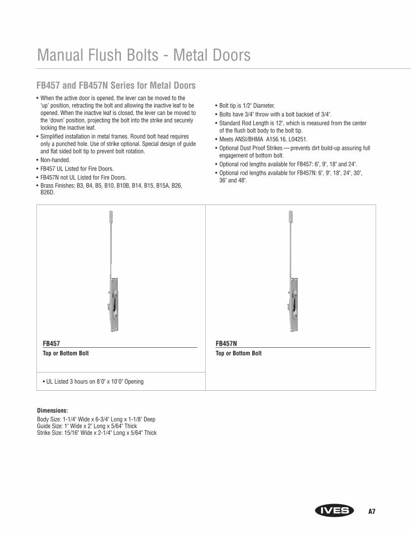
A7
Manual Flush Bolts - Metal Doors
FB457 and FB457N Series for Metal Doors• When the active door is opened, the lever can be moved to the
‘up’ position, retracting the bolt and allowing the inactive leaf to beopened. When the inactive leaf is closed, the lever can be moved tothe ‘down’ position, projecting the bolt into the strike and securelylocking the inactive leaf.
• Simplified installation in metal frames. Round bolt head requiresonly a punched hole. Use of strike optional. Special design of guideand flat sided bolt tip to prevent bolt rotation.
• Non-handed.• FB457 UL Listed for Fire Doors.• FB457N not UL Listed for Fire Doors.• Brass Finishes: B3, B4, B5, B10, B10B, B14, B15, B15A, B26,
B26D.
• Bolt tip is 1/2" Diameter.• Bolts have 3/4" throw with a bolt backset of 3/4".• Standard Rod Length is 12", which is measured from the center
of the flush bolt body to the bolt tip. • Meets ANSI/BHMA A156.16, L04251.• Optional Dust Proof Strikes — prevents dirt build-up assuring full
engagement of bottom bolt.• Optional rod lengths available for FB457: 6", 9", 18" and 24".• Optional rod lengths available for FB457N: 6", 9", 18", 24", 30",
36" and 48".
FB457Top or Bottom Bolt
• UL Listed 3 hours on 8'0" x 10'0" Opening
FB457NTop or Bottom Bolt
Dimensions:Body Size: 1-1/4" Wide x 6-3/4" Long x 1-1/8" DeepGuide Size: 1" Wide x 2" Long x 5/64" ThickStrike Size: 15/16" Wide x 2-1/4" Long x 5/64" Thick

A8
Manual Flush Bolts - Metal Doors
FB458, FB458N and FB0458N Series for Metal Doors• When the active door is opened, the lever can be moved to the ‘up’
position, retracting the bolt and allowing the inactive leaf to beopened. When the inactive leaf is closed, the lever can be moved tothe ‘down’ position, projecting the bolt into the strike and securelylocking the inactive leaf.
• Simplified installation in metal frames. Round bolt head requiresonly a punched hole. Use of strike optional. Special design of guideand flat sided bolt tip to prevent bolt rotation.
• FB458 UL Listed for Fire Doors.• FB458N and FB0458N not UL Listed for Fire Doors.• FB0458N features 1/4" radius corners on body.• Non-handed.
• Brass Finishes: B3, B4, B5, B10, B10B, B14, B15, B15A, B26, B26D.• Bolt tip is 1/2" diameter.• Bolts have 3/4" throw with a bolt backset of 3/4".• Standard Rod Length is 12", which is measured from the center
of the flush bolt body to the bolt tip. • Meets ANSI/BHMA A156.16, L04251.• Optional Dust Proof Strikes— prevents dirt build-up assuring full
engagement of bottom bolt.• Optional Rod Lengths available for FB458: 6", 9", 18" and 24".• Optional Rod Lengths available for FB458N and FB0458N: 6", 9", 18",
24", 30", 36" and 48".
FB458Top or Bottom Bolt
• UL Listed 3 hours on 8'0" x 10'0" Opening
FB458NTop or Bottom Bolt
FB0458NTop or Bottom Bolt
Dimensions:Body Size: 1" Wide x 6-3/4" Long x 1-1/8" DeepGuide Size: 1" Wide x 2" Long x 5/64" ThickStrike Size: 15/16" Wide x 2-1/4" Long x 5/64" Thick

A9
Dust Proof Strikes
DP1 and DP2 Dust Proof Strikes• Designed for use with the bottom bolt of all flush bolts. • Spring-loaded plunger returns to floor or threshold level
anytime flush bolt is retracted, eliminating need to clean standard floor strikes.
• Meets ANSI/BHMA 156.16, L14011.• Finishes: US3, US4, US10, US10B, US26, US26D.
Dimensions:DP1 Face Plate: 1-7/16" DiameterDP2 Face Plate: 1-5/8" Wide x 3-1/2" Long x 1/8" ThickDP1 and DP2 Body: 1-3/16" Diameter x 1-7/8" Deep
DP1Threshold only.
DP2Floor and/or threshold.
DP3 and DP4 Dust Proof Strikes• Designed for use with the bottom bolt of the Ives extension flush
bolts on non-fire rated openings. DP3 for installation in thresholdsup to 1/4" thick. DP4 includes plate for installation in thresholds or floor.
• 3/4" diameter plunger accepts up to 5/8" diameter round bolts or1/2" square bolts.
• Can be locked in up position by rotating plunger with screwdriver or coin. Eliminates trapping of spiked heels.
• Made from polished wrought brass.• Brass Finishes: B3, B4, B5, B10, B10B, B14, B15, B15A, B26, B26D.
Dimensions:DP3 Faceplate: 1-3/8" DiameterDP4 Faceplate: 1-5/8" Wide x 3-1/2" Long x 1/8" thickDP3 and DP4 Body: 1-61/64" Overall Depth, Fits Hole
1-1/16" in Diameter
DP3Threshold only.
DP4Floor and/or threshold.
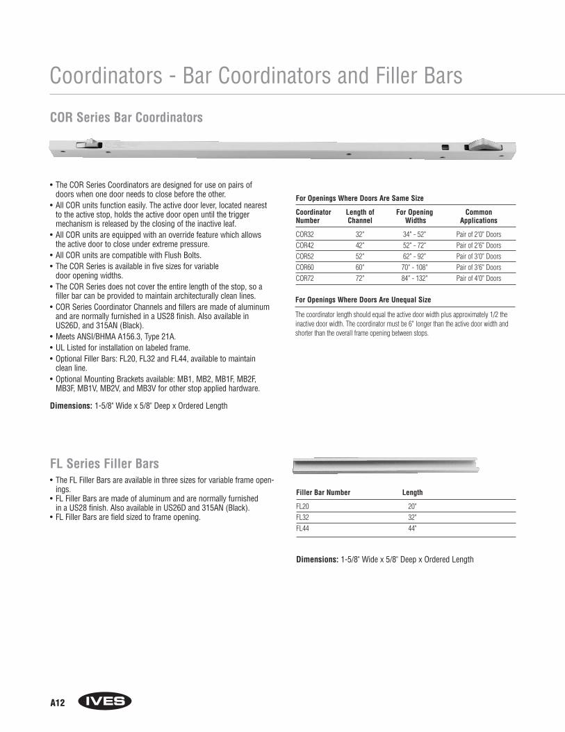
A12
Coordinators - Bar Coordinators and Filler Bars
• The COR Series Coordinators are designed for use on pairs ofdoors when one door needs to close before the other.
• All COR units function easily. The active door lever, located nearestto the active stop, holds the active door open until the triggermechanism is released by the closing of the inactive leaf.
• All COR units are equipped with an override feature which allowsthe active door to close under extreme pressure.
• All COR units are compatible with Flush Bolts. • The COR Series is available in five sizes for variable
door opening widths.• The COR Series does not cover the entire length of the stop, so a
filler bar can be provided to maintain architecturally clean lines. • COR Series Coordinator Channels and fillers are made of aluminum
and are normally furnished in a US28 finish. Also available inUS26D, and 315AN (Black).
• Meets ANSI/BHMA A156.3, Type 21A.• UL Listed for installation on labeled frame.• Optional Filler Bars: FL20, FL32 and FL44, available to maintain
clean line.• Optional Mounting Brackets available: MB1, MB2, MB1F, MB2F,
MB3F, MB1V, MB2V, and MB3V for other stop applied hardware.
COR Series Bar Coordinators
For Openings Where Doors Are Same Size
Coordinator Length of For Opening CommonNumber Channel Widths Applications
COR32 32" 34" - 52" Pair of 2'0" DoorsCOR42 42" 52" - 72" Pair of 2'6" DoorsCOR52 52" 62" - 92" Pair of 3'0" DoorsCOR60 60" 70" - 108" Pair of 3'6" DoorsCOR72 72" 84" - 132" Pair of 4'0" Doors
Filler Bar Number Length
FL20 20"FL32 32"FL44 44"
Dimensions: 1-5/8" Wide x 5/8" Deep x Ordered Length
For Openings Where Doors Are Unequal Size
The coordinator length should equal the active door width plus approximately 1/2 theinactive door width. The coordinator must be 6" longer than the active door width andshorter than the overall frame opening between stops.
FL Series Filler Bars• The FL Filler Bars are available in three sizes for variable frame open-
ings.• FL Filler Bars are made of aluminum and are normally furnished
in a US28 finish. Also available in US26D and 315AN (Black).• FL Filler Bars are field sized to frame opening.
Dimensions: 1-5/8" Wide x 5/8" Deep x Ordered Length
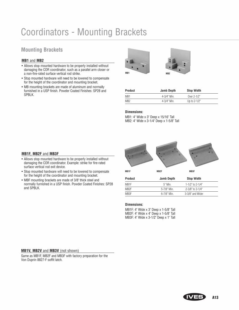
A13
Coordinators - Mounting Brackets
MB1 and MB2• Allows stop mounted hardware to be properly installed without
damaging the COR coordinator, such as a parallel arm closer or a non-fire-rated surface vertical rod strike.
• Stop mounted hardware will need to be lowered to compensate for the height of the coordinator and mounting bracket.
• MB mounting brackets are made of aluminum and normally furnished in a USP finish. Powder Coated Finishes: SP28 andSPBLK.
MB1F, MB2F and MB3F• Allows stop mounted hardware to be properly installed without
damaging the COR coordinator. Example: strike for fire-rated surface vertical rod exit device.
• Stop mounted hardware will need to be lowered to compensate for the height of the coordinator and mounting bracket.
• MBF mounting brackets are made of 3/8" thick steel and normally furnished in a USP finish. Powder Coated Finishes: SP28and SPBLK.
MB1V, MB2V and MB3V (not shown)Same as MB1F, MB2F and MB3F with factory preparation for the Von Duprin 8827-F soffit latch.
Mounting Brackets
MB1 MB2
MB1F MB2F MB3F
Product Jamb Depth Stop Width
MB1 4-3/4" Min. Over 2-1/2"MB2 4-3/4" Min. Up to 2-1/2"
Dimensions: MB1: 4" Wide x 3" Deep x 15/16" TallMB2: 4" Wide x 3-1/4" Deep x 1-5/8" Tall
Product Jamb Depth Stop Width
MB1F 5" Min. 1-1/2" to 2-1/4"MB2F 5-7/8" Min. 2-3/8" to 3-1/4"MB3F 6-7/8" Min. 3-3/8" and Wider
Dimensions: MB1F: 4" Wide x 3" Deep x 1-5/8" TallMB2F: 4" Wide x 4" Deep x 1-5/8" TallMB3F: 4" Wide x 3-1/2" Deep x 1" Tall

Exit Device Exit Device Device Maximum Coordinator Coordinator Mounting BracketManufacturer Number Backset Active Door Size Needed Cutout Type Needed
Von Duprin 5547-F 2-3/8" 33" 42" A None43" 52"51" 60"63" 72"
Von Duprin 8827-F 2-3/4" 33" 42" B MB1V, MB2V43" 52" or MB3V51" 60"63" 72"
Von Duprin 8847-F 2-3/8" 33" 42" C None43" 52"51" 60"63" 72"
Von Duprin 33/3547 2-3/4" 33" 42" D None33/3547-F 43" 52"98/9947 51" 60"
98/9947-F 64" 72"Von Duprin 33/3548 2-3/4" 33" 42" D None
33/3548-F 43" 52"98/9948 51" 60"
98/9948-F 64" 72"Von Duprin 33/3547WDC 1-5/16" 34" 42" E None
33/3547WDC-F 44" 52"98/9947WDC 52" 60"
98/9947WDC-F 65" 72"Monarch 17-C 2-3/4" 33" 42" F None
F-17-C 43" 52"18-C 51" 60"
F-18-C 63" 72"XX-C
F-XX-CMonarch 17-C-WDC 2-13/16" 33" 42" G None
F-17-C-WDC 43" 52"18-C-WDC 51" 60"
F-18-C-WDC 63" 72"XX-C-WDC
F-XX-C-WDC
A14
Coordinators
Special Factory Preparation for Use with Vertical Rod Exit Devices• Coordinators may need to be prepared at the factory for use
with some surface and concealed vertical rod exit devices. (See Chart below)
• If exit device not listed in chart, the information shown on the illustration will be needed.
1. Exit Device Manufacturer and Model No.2. Active Net Door Size, “X”3. Inactive Net Door Size, “Y”4. Exit Device Backset, “U”5. Stop Width, “W”6. Stop Thickness if other than 5/8", “V”
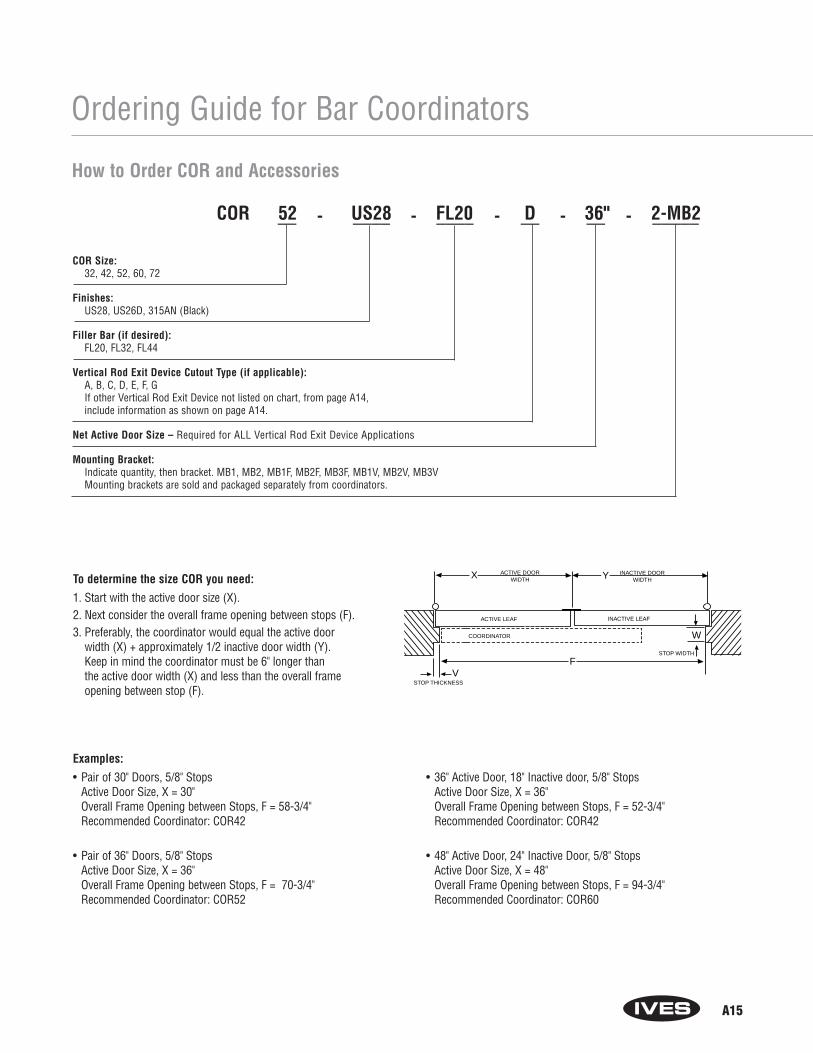
A15
Ordering Guide for Bar Coordinators
To determine the size COR you need:
1. Start with the active door size (X).2. Next consider the overall frame opening between stops (F). 3. Preferably, the coordinator would equal the active door
width (X) + approximately 1/2 inactive door width (Y). Keep in mind the coordinator must be 6" longer than the active door width (X) and less than the overall frame opening between stop (F).
Examples:
• Pair of 30" Doors, 5/8" Stops Active Door Size, X = 30"Overall Frame Opening between Stops, F = 58-3/4"Recommended Coordinator: COR42
• Pair of 36" Doors, 5/8" StopsActive Door Size, X = 36"Overall Frame Opening between Stops, F = 70-3/4"Recommended Coordinator: COR52
COORDINATOR
ACTIVE LEAF INACTIVE LEAF
ACTIVE DOORWIDTH
INACTIVE DOORWIDTH
X Y
W
VSTOP THICKNESS
STOP WIDTH
F
COR 52 US28 FL20 D 36" 2-MB2__ - ____ - ____ - __ - __ - _____
How to Order COR and Accessories
COR Size: 32, 42, 52, 60, 72
Finishes: US28, US26D, 315AN (Black)
Filler Bar (if desired): FL20, FL32, FL44
Vertical Rod Exit Device Cutout Type (if applicable): A, B, C, D, E, F, GIf other Vertical Rod Exit Device not listed on chart, from page A14,include information as shown on page A14.
Net Active Door Size – Required for ALL Vertical Rod Exit Device Applications
Mounting Bracket:Indicate quantity, then bracket. MB1, MB2, MB1F, MB2F, MB3F, MB1V, MB2V, MB3VMounting brackets are sold and packaged separately from coordinators.
• 36" Active Door, 18" Inactive door, 5/8" StopsActive Door Size, X = 36"Overall Frame Opening between Stops, F = 52-3/4"Recommended Coordinator: COR42
• 48" Active Door, 24" Inactive Door, 5/8" StopsActive Door Size, X = 48"Overall Frame Opening between Stops, F = 94-3/4"Recommended Coordinator: COR60

C8
Architectural Door Trim
How to Order8 ___ - ____ -____ - ____ - ____
Model: 200 Push Plate, 300 Pull Plate, less pull
Hole Spacing: (for Pull Plate only)5 for 5-1/4"6 for 6" 8 for 8"0 for 10"
Finishes: US3, US4, US5, US10, US10B, US15, US15A, US26, US26D, US28, US32, US32D
Size: 3 x 12, 3-1/2 x 15, 4 x 16, 6 x 16, 8 x 16
Special Options: (specify handing for plates over 4" wide)CFC Cylinder cutoutCTC Thumbturn cutout
8200 Series Push Plates and 8300 Series Pull Plates• Made from the finest architectural aluminum, brass,
and stainless steel.• For Push Plate sizes other than listed, contact our Customer
Service Department or your local sales representative.• All aluminum, brass, and stainless steel Push Plates meet
ANSI A156.6 requirements for .050" thickness.• Each Push Plate is packaged individually wrapped with
mounting screws.• For special mounting methods other than standard,
see pages C11 - C13.
8200 Push Plate8300 Pull Plate (less pull)
Available Sizes
3" x 12"3.5" x 15"4" x 16"6" x 16"8" x 16"
Push and Pull Plates Cut for Cylinder or Thumbturns• All plates may be ordered with cutout for cylinder or thumbturn.
Standard cutouts are positioned 2" from top of plate and centered on plates up to 4" wide or 2" from edge on plates over 4" wide. Specify hand of door when ordering cutout forplates wider than 4". On pull plates, if the pulls center-to-centerdimension interferes with the cutout for the cylinder or thumbturn, please provide drawing of cutout location whenordering.
• Standard size for cylinder cutouts is 1-1/4" diameter and forthumbturn cutout is 3/8" diameter.
• When ordering, add suffix CFC for cut for cylinder, and CFT for cut for thumbturn to product number.

Floor Stops
D5
FS441Features:• Designed to blend well with all types of construction and provide a minimum of
hindrance to cleaning efforts.• Accommodates door undercut up to 1-1/2".• Heavy-Duty cast brass or aluminum construction.• Non-marring rubber bumper.• FS441 packed with expansion shield and tampin.• FS441-WS packed with wood screws.• FS441 meets ANSI/BHMA 156.16, L12131 for brass and L32131 for aluminum.
FS441-WS meets ANSI/BHMA 156.16, L12121 for brass and L32121 for aluminum.• Finishes: US3, US4, US5, US10, US10B, US14, US15, US15A, US26, US26D, US28.
FS442Features:• Designed to blend well with all types of construction and provide a minimum of
hindrance to cleaning efforts.• Accommodates door undercut up to 2".• Heavy-Duty cast brass or aluminum construction.• Non-marring rubber bumper.• FS442 packed with expansion shield and tampin.• FS442-WS packed with wood screws.• FS442 meets ANSI/BHMA 156.16, L12131 for brass and L32131 for aluminum.
FS442-WS meets ANSI/BHMA 156.16, L12121 for brass and L32121 for aluminum.• Finishes: US3, US4, US5, US10, US10B, US14, US15, US15A, US26, US26D, US28.
Product No. Overall Height Overall Length Base DepthFS442 2-7/8" 2-3/4" 1-5/8"FS442-WS 2-7/8" 2-3/4" 1-5/8"
Product No. Overall Height Overall Length Base Depth
FS441-MS 2-1/8" 2-7/8" 1-5/8"FS441-WS 2-1/8" 2-7/8" 1-5/8"

Floor Stops
D6
FS444Features:• Ideal for interior or exterior use.• Cast brass construction.• Accommodates door undercut up to 2-1/2".• Non-marring rubber tip.• Packed with expansion shield and lead shield.• Meets ANSI/BHMA 156.16, L12131 for brass, and L32131 for aluminum.• Finishes: US3, US4, US5, US10, US10B, US14, US15, US15A, US26, US26D, US28.
FS448Features:• Ideal for interior or exterior use.• Cast brass construction.• Accommodates door undercut up to 2-1/2".• Non-marring rubber tip.• Packed with wood screws.• Meets ANSI/BHMA 156.16, L12121, for brass and L32121 for aluminum.• Finishes: US3, US4, US5, US10, US10B, US14, US15, US15A, US26, US26D, US28.
Product No. Overall Height Base DiameterFS448 3" 2-1/2"
Product No. Overall Height Base Diameter
FS444 3" 2-1/2"

Wall Bumpers
D14
WS406CVX & WS407CVXWS406CCV & WS407CCVFeatures:• Constructed in sturdy yet economical wrought base of brass, aluminum or stainless
steel construction.• Feature concealed tamper-proof mounting.• Shipped factory preassembled backplate to reduce installation cost.• Easy installation by inserting screwdriver through small hole in rubber.• The WS406CVX unit is designed with a convex rubber bumper, packed with wood screw and
plastic anchor.• The WS406CCV unit is designed with a concave rubber bumper, which avoids damage to
locks with projecting buttons, packed with wood screw and plastic anchor.• The WS407CVX unit is designed with a convex rubber bumper packed with screw and
drywall anchor.• The WS407CCV unit is designed with a concave rubber bumper which avoids damage to
locks with projecting buttons and is packed with screw and drywall anchor.• WS406CVX & WS407CVX meets ANSI/BHMA 156.16 L22201 for brass, L42101 for
aluminum and L52101 for stainless steel.• WS406CCV &WS407CCV meets ANSI/BHMA 156.16 L22251 for brass and L42251 for
aluminum, and L52251 for stainless steel.• Finishes: US3, US4, US5, US10, US10B, US14, US15, US15A, US26, US26D, US28, US32D.
Mounting Base Base OverallProduct No. Hardware Diameter Thickness Projection
Wood screw,WS406CVX plastic anchor 2-1/2" 3/8" 1"
Wood screw,WS406CCV plastic anchor 2-1/2" 3/8" 1"
Screw, DrywallWS407CVX Anchor 2-1/2" 3/8" 1"
Screw, DrywallWS407CCV Anchor 2-1/2" 3/8" 1"
WS406CVX & WS407CVX
WS406CCV & WS407CCV

Wall Stops
WS443Features:• Constructed in brass.• Ideal for interior or exterior use.• Non-marring rubber tip.• Packed with expansion shield and lead shield.• Meets ANSI/BHMA 156.16, L12021 for brass and L32021 for aluminum.• Finishes: US3, US4, US5, US10, US10B, US14, US15, US15A, US26, US26D, US28.
WS447Features:• Constructed in brass or aluminum.• Ideal for interior or exterior use.• Non-marring rubber tip.• Furnished with 3 mounting holes for drywall mounting.• Packed with wood screws.• Meets ANSI/BHMA 156.16, L12011 for brass and L32011 for aluminum.• Finishes: US3, US4, US5, US10, US10B, US14, US15, US15A, US26, US26D, US28.
Base OverallProduct No. Diameter ProjectionWS443 2-1/4" 3-11/16"
Base OverallProduct No. Diameter ProjectionWS447 2-1/4" 3-11/16"
D17
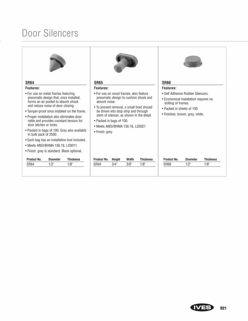
Door Silencers
SR64Features:• For use on metal frames featuring
pneumatic design that, once installed,forms an air pocket to absorb shock and reduce noise of door closing.
• Tamper-proof once installed on the frame.• Proper installation also eliminates door
rattle and provides constant tension fordoor latches or locks.
• Packed in bags of 100. Grey also availablein bulk pack of 2500.
• Each bag has an installation tool included.• Meets ANSI/BHMA 156.16, L03011.• Finish: grey is standard. Black optional.
SR65Features:• For use on wood frames, also feature
pneumatic design to cushion shock andabsorb noise.
• To prevent removal, a small brad shouldbe driven into stop strip and throughstem of silencer, as shown in the detail.
• Packed in bags of 100.• Meets ANSI/BHMA 156.16, L03021• Finish: grey.
SR66Features:• Self Adhesive Rubber Silencers.• Economical installation requires no
drilling of frames.• Packed in sheets of 100.• Finishes: brown, grey, white.
Product No. Diameter ThicknessSR64 1/2" 1/8"
Product No. Height Width ThicknessSR64 3/4" 3/8" 1/8"
Product No. Diameter ThicknessSR66 1/2" 1/8"
D21
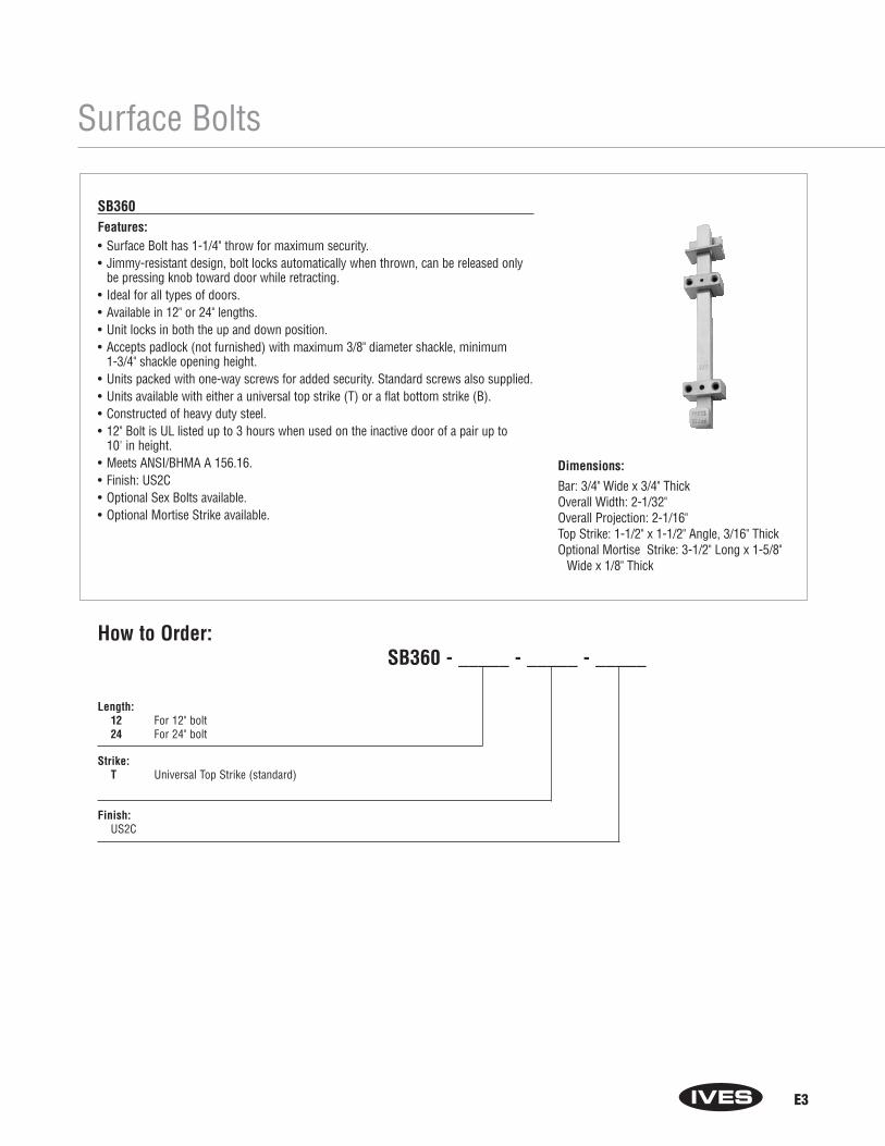
E3
Surface Bolts
SB360Features:• Surface Bolt has 1-1/4" throw for maximum security.• Jimmy-resistant design, bolt locks automatically when thrown, can be released only
be pressing knob toward door while retracting.• Ideal for all types of doors.• Available in 12" or 24" lengths.• Unit locks in both the up and down position.• Accepts padlock (not furnished) with maximum 3/8" diameter shackle, minimum
1-3/4" shackle opening height.• Units packed with one-way screws for added security. Standard screws also supplied.• Units available with either a universal top strike (T) or a flat bottom strike (B).• Constructed of heavy duty steel.• 12" Bolt is UL listed up to 3 hours when used on the inactive door of a pair up to
10' in height.• Meets ANSI/BHMA A 156.16.• Finish: US2C• Optional Sex Bolts available.• Optional Mortise Strike available.
Dimensions:
Bar: 3/4" Wide x 3/4" ThickOverall Width: 2-1/32"Overall Projection: 2-1/16"Top Strike: 1-1/2" x 1-1/2" Angle, 3/16" ThickOptional Mortise Strike: 3-1/2" Long x 1-5/8"
Wide x 1/8" Thick
Length: 12 For 12" bolt24 For 24" bolt
Strike: T Universal Top Strike (standard)
Finish:US2C
How to Order:SB360 - _____ - _____ - _____

C14
Architectural Door Trim
Mop Plates• Protect the bottom of the
pull side of door subject to cleaning and mopping procedures.
• Size Ranges:4" to 6" high, 22" to 48" wide
Kick Plates• Protect the bottom of the
push side of doors subject to scuffing from foot traffic.
• Recommended for all doors subject to normaluse (especially doors using a closer).
• Size Ranges:8" to 24" high, 22" to 48" wide
Stretcher Plates• Protect doors at specific
areas where consistent contact is made by stretchers, service carts or other equipment.
• Usually applied to push side of doors.
• Specify “B4E” Option forbeveled edges.
• Size Ranges:6" to 8" high, 22" to 48" wide
Armor Plates• Protect lower half of doors
from abuse by hard carts,trucks and rough usage.
• Usually applied to push sideof single doors and bothsides of double acting doors.
• Size Ranges:26" to 48" high, 22" to 48" wide
Series 8400 Door Protection Plates.050" ThicknessFeatures:• Door Protection Plates are fabricated from the finest architectural
aluminum, brass, and stainless steel, or 1/8" thick clear acrylicplastic or black or brown high impact polyethylene.
• All aluminum, brass, bronze and stainless steel Door ProtectionPlates meet ANSI A156.6 requirements for .050" thickness.
• Optional Beveling—For beveling of top and two sides of plates suffix with B3E, and for beveling of four sides suffix with B4E. Plastic plates are beveled on all four sides as standard.
• Each plate is packaged carefully wrapped in strong kraft paper with#6 x 5/8" oval head, undercut sheet metal screws plated to match,for easy installation on hollow metal, laminate, or wood doors. Allplates are packaged in heavy duty corrugated cardboard; largerplates are enclosed in a wooden frame.
• Use No. 8401 Kickplate Gasket Tape as a buffer between brasskickplates and metal doors to help prevent tarnishing which mayresult from electrolytic oxidation. One package provides enoughdouble-sided adhesive-backed foam tape for the perimeter of an 8" x 34" plate.
• Finishes:Brass: B3, B4, B5, B10, B10B (for heights over 24", check withcustomer serivce)Stainless Steel: S32D, S32Aluminum: PA28Plastic: BLK, BRN, CLR
How to Order 8400 ____ - _____ x _____ - _____Finish
Height: 4" up to 48" in 1/2" increments (For brass kick plates over 24", check with customer service.)
Width:22" up to 48" in 1/2" increments
Options: (Only for metal plates)B3E for Bevel Top and 2 EdgesB4E for Bevel 4 EdgesCS for Counter Sink HolesES for Extra row of Screws

Floor Stops – Dome
D2
FS436 Dome StopFeatures:• For doors without threshold.• Heavy-Duty Cast Dome Stops constructed of brass, bronze or aluminum.• Gray, non-marring rubber bumper.• Packed with wood screw and plastic anchor, specify Tampin (TPN) or lead expansion
shield (LS), if required.• Meets ANSI/BHMA 156.6, L12141 for brass or bronze and L32141 for aluminum.• Finishes: US3, US4, US5, US10, US10B, US14, US15, US15A, US26, US26D and US28.
R435 RiserFeatures:• Extruded aluminum, mill finish.• For conversion of FS436 Dome Stop to carpet installation.• Packed with wood screws, lead shield and stud. Specify
Tampin (TPN) if required.• Available in 1/4", 3/8", 1/2", 5/8", 3/4" and 1" height.
Product No. SizeR435 1" x 1-3/8" Oval
Product No. Overall Height Base Height Base Diameter
FS436 1" 3/16" 1-3/4" x 2" Oval
PADFLOOR
1" ORLESS
1"
1-7/16"
Model:436 Dome Stop Only435 Riser Only436 x 435 Dome Stop & Riser
Riser Size:Blank No riser1/4 for 1/4"3/8 for 3/8"1/2 for 1/2"5/8 for 5/8"3/4 for 3/4"1 for 1"
Finishes:US3, US4, US5, US10, US10B, US14, US15, US15A, US26, US26D, US28
Mounting:Blank StandardTPN TampinLS Lead Expansion Shield
How to Order:FS ___ - ___ - ___ - ____

AR
CH
IT
EC
TU
RA
LH
IN
GE
S
5PB1 Steel with steel pin
5PB1 Brass with stainless steel pin
5PB1 Stainless steel with stainless steel pin (630 finish)
NRP = Non-Removable Pin
• Dimensions & tolerances conform to ANSI - A156.7• Packed with wood and machine screws• 5PB1 Steel description conforms to ANSI - A8133• 5PB1 Brass conforms to ANSI - A2133• 5PB1 Stainless Steel description conforms to ANSI - A5133
Size (Inches) Size (mm) Gauge
3.5 x 3.5 89 x 89 0.123
4.5 x 4 114 x 102 0.134
4.5 x 4.5 114 x 114 0.134
PLAIN BEARING • LOW FREQUENCY • STANDARD WEIGHT
For use on Standard Weight Doors with Low Frequency Usage, not intended for usewith door closing devices.
Full Mortise Hinges - 5 Knuckle
5PB15 Knuckle, Plain Bearing
5BB15 Knuckle, Ball Bearing
5BB1 Steel with steel pin
5BB1 Brass with stainless steel pin
5BB1 Stainless steel with stainless steel pin (630 finish only)
NRP = Non-Removable Pin
• Dimensions & tolerances conform to ANSI - A156.7• 5BB1 Steel description conforms to ANSI - A8112• 5BB1 Brass conforms to ANSI - A2112• 5BB1 Stainless description conforms to ANSI - A5112• Packed with wood and machine screws
Size (Inches) Size (mm) Gauge
4 x 4 102 x 102 0.130
4.5 x 4 114 x 102 0.134
4.5 x 4.5 114 x 114 0.134
4.5 x 5 114 x 127 0.146
5 x 4.5 127 x 114 0.146
2 BALL BEARING • MEDIUM FREQUENCY • STANDARD WEIGHT
For use on Standard Weight Doors with Medium Frequency Usage
5BB1RC5 Knuckle, Ball Bearing, Round Corner
5BB1 Steel with steel pin
NRP = Non-Removable Pin
• Dimensions & tolerances conform to ANSI - A156.7• 1/4" radius• 5BB1 Steel description conforms to ANSI - A8112• Packed with wood and machine screws
Size (Inches) Size (mm) Gauge
3.5 x 3.5 89 x 89 0.123
4.5 x 4 114 x 102 0.134
2 BALL BEARING • MEDIUM FREQUENCY • STANDARD WEIGHT
For use on Standard Weight Doors with Medium Frequency Usage

9
Full Mortise Hinges - 5 Knuckle
5BB1SC5 Knuckle, Ball Bearing,Swing Clear
5BB1SC Steel with steel pin
• Dimensions & tolerances conform to ANSI - A156.7• 5BB1SC Steel Description conforms to ANSI - A8122• Packed with flat head wood and machine screws
Size (Inches) Size (mm) Gauge
4.5 114 0.134
5 127 0.134
2 BALL BEARING • MEDIUM FREQUENCY
STANDARD WEIGHT • SWING CLEAR
Designed to completely clear the opening when door is opened 92 degrees.
Pins and tips are reversible.
AR
CH
IT
EC
TU
RA
LH
IN
GE
S
5BB1HW5 Knuckle, Ball Bearing,Heavy Weight
5BB1HW Steel with steel pin
5BB1HW Brass with stainless steel pin
5BB1HW Stainless steel with stainless steel pin (630 finish only)
NRP = Non-Removable Pin
• Dimensions & tolerances conform to ANSI - A156.7• 5BB1HW Steel description conforms to ANSI - A8111• 5BB1HW Brass description conforms to ANSI - A2111• 5BB1HW Stainless description conforms to ANSI - A5111• Packed with wood and machine screws
Size (Inches) Size (mm) Gauge
4.5 x 4 114 x 102 0.180
4.5 x 4.5 114 x 114 0.180
4.5 x 5 114 x 127 0.190
5 x 5 127 x 127 0.190
4 BALL BEARING • HIGH FREQUENCY • HEAVY WEIGHT
For use on Heavy Weight Doors or High Frequency Usage
5BB1HWRC5 Knuckle, Ball Bearing,Heavy Weight, Round Corner
5BB1HW Steel with steel pin
5BB1HW Brass with stainless steel pin
5BB1HW Stainless steel with stainless steel pin (630 finish only)
NRP = Non-Removable Pin
• Dimensions & tolerances conform to ANSI - A156.7• 1/4" radius• 5BB1HW Steel description conforms to ANSI - A8111• 5BB1HW Brass description conforms to ANSI - A2111• 5BB1HW Stainless description conforms to ANSI - A5111• Packed with wood and machine screws
Size (Inches) Size (mm) Gauge
4.5 x 4 114 x 102 0.180
4 BALL BEARING • HIGH FREQUENCY • HEAVY WEIGHT
For use on Heavy Weight Doors or High Frequency Usage
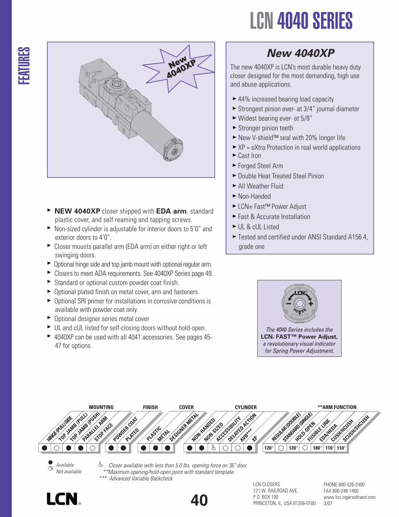
LCN CLOSERS121 W. RAILROAD AVE.P.O. BOX 100PRINCETON, IL, USA 61356-0100
PHONE 800-526-2400FAX 800-248-1460www.lcn.ingersollrand.com3/07
NEW 4040XP closer shipped with EDA arm, standardplastic cover, and self reaming and tapping screws.Non-sized cylinder is adjustable for interior doors to 5’0” andexterior doors to 4’0”.Closer mounts parallel arm (EDA arm) on either right or leftswinging doors.Optional hinge side and top jambmount with optional regular arm.Closers to meet ADA requirements. See 4040XP Series page 49.Standard or optional custom powder coat finish.Optional plated finish on metal cover, arm and fasteners.Optional SRI primer for installations in corrosive conditions isavailable with powder coat only.Optional designer series metal coverUL and cUL listed for self-closing doors without hold-open.4040XP can be used with all 4041 accessories. See pages 45-47 for options.
FEATU
RES
LCN 4040 SERIES
DESIGNER M
ETAL
PLASTIC
METAL
HINGE(PULL)SIDE
TOP JAMB (PULL)
TOP JAMB (PUSH)
PARALLELARM
STOPFACE
MOUNTING COVER
120° 120° 180° 110°110°STANDARD(SINGLE)
REGULAR(DOUBLE)
HOLD-OPEN
FUSIBLELINK
EDA/HEDA
CUSH/HCUSH
SCUSH/SHCUSH
**ARM FUNCTIONFINISH CYLINDER
NON-HANDED
NON-SIZED
ACCESSIBILITY
DELAYED ACTION
AVB***
XPPOWDER COAT
PLATED
AvailableNot available
Closer available with less than 5.0 lbs. opening force on 36" door.**Maximum opening/hold-open point with standard template.
*** Advanced Variable Backcheck
40
New 4040XPThe new 4040XP is LCN’s most durable heavy dutycloser designed for the most demanding, high useand abuse applications.
44% increased bearing load capacityStrongest pinion ever- at 3/4” journal diameterWidest bearing ever- at 5/8”Stronger pinion teethNew V-shield™ seal with 20% longer lifeXP = eXtra Protection in real world applicationsCast IronForged Steel ArmDouble Heat Treated Steel PinionAll Weather FluidNon-HandedLCN® Fast™ Power AdjustFast & Accurate InstallationUL & cUL ListedTested and certified under ANSI Standard A156.4,grade one
The 4040 Series includes theLCN® FAST™ Power Adjust,
a revolutionary visual indicatorfor Spring Power Adjustment.

HINGE (PULL) SIDEMOUNTING
MAXIMUM OPENINGTemplating allows up to 120°.
Hold-open points 90° up to 120° withhold-open arm.
LCN 4040 SERIES
Butt Hinges should not exceed 5” (127 mm) in width.
Auxiliary Stop is recommended at hold-open point or where a doorcannot swing beyond 120°.
Reveal should not exceed 3/4” (19 mm) for regular arm or hold-open arm.
Top Rail less than 3 3/4” (95 mm) requires PLATE, 4040-18.Plate requires 2” (51 mm) minimum. With Designer Series metal cover,use PLATE, 4040-18DS1
Clearance of 2 3/8” (60 mm) behind door required for 90° installation.2 7/8” (73 mm) for Designer Series metal covers
Delayed Action (not available on 4040XP) Add suffix “DEL” to selectedcylinder (eg. 4041 DEL). Delays closing from 120° to 70°.Delay time adjustable up to approximately 1 minute.
Bull Nose Trim requires SOFFIT SHOE, 4040-65.
Corner Bracket available for doors where top jamb or parallel armmounting can not be used.4040-16 allows 110° opening. Projects 5” (127 mm) from stop, 12 13/16”(325 mm) from frame.4040-17 allows 100° opening with certain auxiliary door holders (consultfactory). Projects 6 3/8” (162 mm) from stop, 13 11/16” (348 mm)from frame.
MOUN
TINGD
ETAILS
Options4040XP cylinder4041 Delayed action cylinder.Hold-open arm.Metal or lead lined cover.Corner bracket.Designer Series metal cover.
Special TemplatesCustomized installation templatesor products may be available tosolve unusual applications.Contact LCN for assistance.
41
Optional, Non-handedDesigner Series
Metal Cover
LCN CLOSERS121 W. RAILROAD AVE.P.O. BOX 100PRINCETON, IL, USA 61356-0100
PHONE 800-526-2400FAX 800-248-1460www.lcn.ingersollrand.com3/07

LCN CLOSERS121 W. RAILROAD AVE.P.O. BOX 100PRINCETON, IL, USA 61356-0100
PHONE 800-526-2400FAX 800-248-1460www.lcn.ingersollrand.com3/07
LCN 4040 SERIESMO
UNTIN
GDETA
ILS TOP JAMB (PUSH SIDE)MOUNTING
MAXIMUM OPENINGTemplating allows up to 120°.
Hold-open points 85° up to 120° withhold-open arm.
Butt Hinges should not exceed 5” (127 mm) in width.
Auxiliary Stop is recommended at hold-open point or where thedoor cannot swing 120°.
Reveal of 2 9/16” (65 mm) allows 120° opening for REGULAR ARM orstandard HOLD-OPEN ARM. 4 13/16” (122 mm) allows up to 120°opening with LONG ARM where standard rod and shoe is replacedwith optional LONG ROD AND SHOE 4040-79LR. Use H-LONG ARMwith LONG HEAD AND TUBE, 4040-78HL for hold-open. 8” (203 mm)allows up to 120° opening with EXTRA LONG ARM where standardrod and shoe is replaced with optional EXTRA LONG ROD AND SHOE,4040-79ELR.
Top Rail requires 1 1/4" (32 mm) minimum.2 1/4" (57 mm) minimum with closer on PLATE, 4040-18TJ.3" (76 mm) minimum with closer on PLATE, 4040-18G. With DesignerSeries metal cover, use PLATE, 4040-18TJDS1
Head Frame less than 3 1/2” (89 mm) requires PLATE, 4040-18TJ.With flush ceiling, use PLATE, 4040-18G.Either plate requires 1 3/4” (44 mm) minimum.
Delayed Action (not available on 4040XP) Add suffix “DEL” toselected cylinder (eg. 4041 DEL). Delays closing from 120° to 80°.Delay time adjustable up to approximately 1 minute.
Options4040XP cylinder4041Delayed action cylinder.Long arm, extra long arm, hold-open arm, long hold-open arm.Metal or lead lined cover.Designer Series metal cover.
Special TemplatesCustomized installation templatesor products may be available tosolve unusual applications.Contact LCN for assistance.
42
Optional, Non-handedDesigner Series
Metal Cover
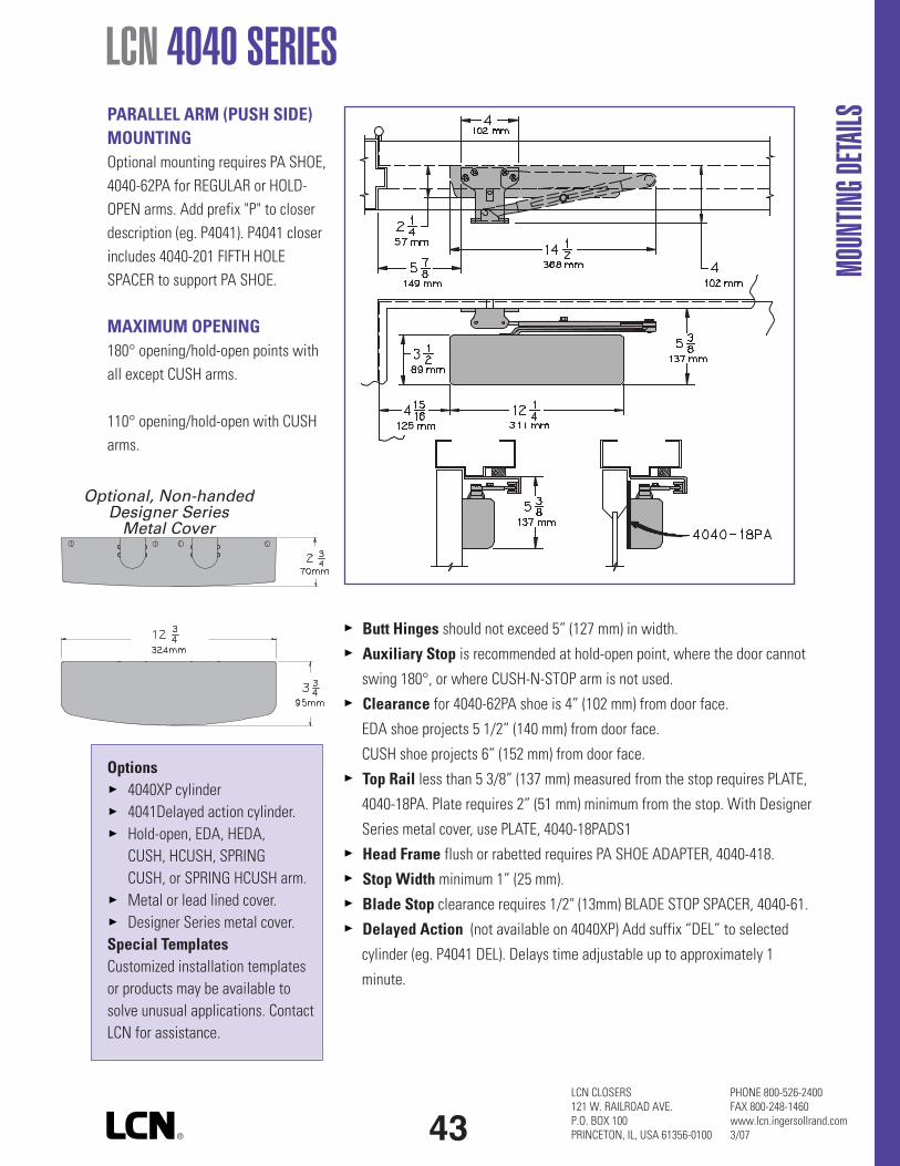
LCN 4040 SERIES
MOUN
TINGD
ETAILSPARALLEL ARM (PUSH SIDE)
MOUNTINGOptional mounting requires PA SHOE,4040-62PA for REGULAR or HOLD-OPEN arms. Add prefix "P" to closerdescription (eg. P4041). P4041 closerincludes 4040-201 FIFTH HOLESPACER to support PA SHOE.
MAXIMUM OPENING180° opening/hold-open points withall except CUSH arms.
110° opening/hold-open with CUSHarms.
Butt Hinges should not exceed 5” (127 mm) in width.
Auxiliary Stop is recommended at hold-open point, where the door cannot
swing 180°, or where CUSH-N-STOP arm is not used.
Clearance for 4040-62PA shoe is 4” (102 mm) from door face.
EDA shoe projects 5 1/2” (140 mm) from door face.
CUSH shoe projects 6” (152 mm) from door face.
Top Rail less than 5 3/8” (137 mm) measured from the stop requires PLATE,
4040-18PA. Plate requires 2” (51 mm) minimum from the stop. With Designer
Series metal cover, use PLATE, 4040-18PADS1
Head Frame flush or rabetted requires PA SHOE ADAPTER, 4040-418.
Stop Width minimum 1” (25 mm).
Blade Stop clearance requires 1/2" (13mm) BLADE STOP SPACER, 4040-61.
Delayed Action (not available on 4040XP) Add suffix “DEL” to selected
cylinder (eg. P4041 DEL). Delays time adjustable up to approximately 1
minute.
Options4040XP cylinder4041Delayed action cylinder.Hold-open, EDA, HEDA,CUSH, HCUSH, SPRINGCUSH, or SPRING HCUSH arm.Metal or lead lined cover.Designer Series metal cover.
Special TemplatesCustomized installation templatesor products may be available tosolve unusual applications. ContactLCN for assistance.
43LCN CLOSERS121 W. RAILROAD AVE.P.O. BOX 100PRINCETON, IL, USA 61356-0100
PHONE 800-526-2400FAX 800-248-1460www.lcn.ingersollrand.com3/07
Optional, Non-handedDesigner Series
Metal Cover
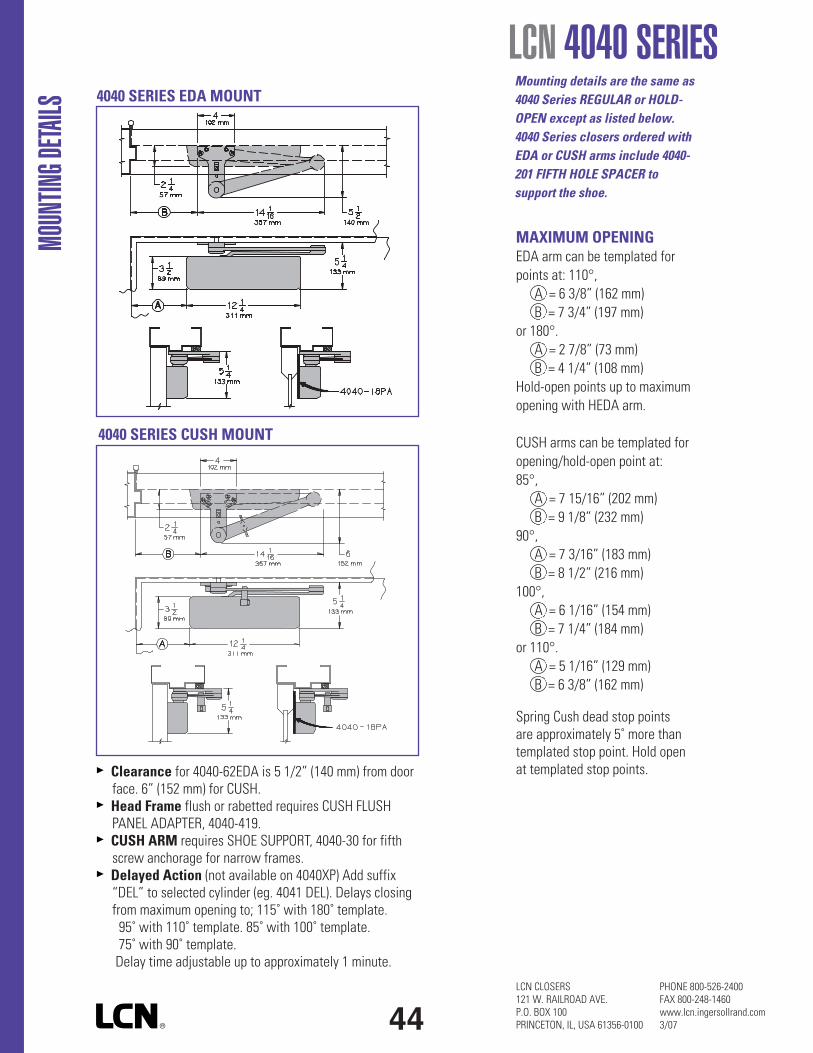
LCN CLOSERS121 W. RAILROAD AVE.P.O. BOX 100PRINCETON, IL, USA 61356-0100
PHONE 800-526-2400FAX 800-248-1460www.lcn.ingersollrand.com3/07
LCN 4040 SERIESMO
UNTIN
GDETA
ILS
Clearance for 4040-62EDA is 5 1/2” (140 mm) from doorface. 6” (152 mm) for CUSH.Head Frame flush or rabetted requires CUSH FLUSHPANEL ADAPTER, 4040-419.CUSH ARM requires SHOE SUPPORT, 4040-30 for fifthscrew anchorage for narrow frames.Delayed Action (not available on 4040XP) Add suffix“DEL” to selected cylinder (eg. 4041 DEL). Delays closingfrom maximum opening to; 115˚ with 180˚ template.95˚ with 110˚ template. 85˚ with 100˚ template.75˚ with 90˚ template.Delay time adjustable up to approximately 1 minute.
4040 SERIES EDA MOUNT
4040 SERIES CUSH MOUNT
MAXIMUM OPENINGEDA arm can be templated forpoints at: 110°,
A = 6 3/8” (162 mm)B = 7 3/4” (197 mm)
or 180°.A = 2 7/8” (73 mm)B = 4 1/4” (108 mm)
Hold-open points up to maximumopening with HEDA arm.
CUSH arms can be templated foropening/hold-open point at:85°,
A = 7 15/16” (202 mm)B = 9 1/8” (232 mm)
90°,A = 7 3/16” (183 mm)B = 8 1/2” (216 mm)
100°,A = 6 1/16” (154 mm)B = 7 1/4” (184 mm)
or 110°.A = 5 1/16” (129 mm)B = 6 3/8” (162 mm)
Spring Cush dead stop pointsare approximately 5˚ more thantemplated stop point. Hold openat templated stop points.
Mounting details are the same as4040 Series REGULAR or HOLD-OPEN except as listed below.4040 Series closers ordered withEDA or CUSH arms include 4040-201 FIFTH HOLE SPACER tosupport the shoe.
44
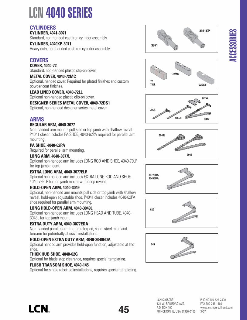
LCN 4040 SERIES
ACCE
SSOR
IES
CYLINDERSCYLINDER, 4041-3071Standard, non-handed cast iron cylinder assembly.CYLINDER, 4040XP-3071Heavy duty, non-handed cast iron cylinder assembly.
COVERSCOVER, 4040-72Standard, non-handed plastic clip-on cover.METAL COVER, 4040-72MCOptional, handed cover. Required for plated finishes and custompowder coat finishes.LEAD LINED COVER, 4040-72LLOptional non-handed plastic clip-on cover.DESIGNER SERIESMETAL COVER, 4040-72DS1Optional, non-handed designer series metal cover.
ARMSREGULAR ARM, 4040-3077Non-handed arm mounts pull side or top jamb with shallow reveal.P4041 closer includes PA SHOE, 4040-62PA required for parallel armmounting.PA SHOE, 4040-62PARequired for parallel arm mounting.LONG ARM, 4040-3077LOptional non-handed arm includes LONG ROD AND SHOE, 4040-79LRfor top jamb mount.EXTRA LONG ARM, 4040-3077ELROptional non-handed arm includes EXTRA LONG ROD AND SHOE,4040-79ELR for top jamb mount with deep reveal.HOLD-OPEN ARM, 4040-3049Optional, non-handed arm mounts pull side or top jamb with shallowreveal, hold-open adjustable shoe. P4041 closer includes 4040-62PAshoe required for parallel arm mounting.LONG HOLD-OPEN ARM, 4040-3049LOptional non-handed arm includes LONG HEAD AND TUBE, 4040-3048L for top jamb mount.EXTRA DUTY ARM, 4040-3077EDANon-handed parallel arm features forged, solid steel main andforearm for potentially abusive installations.HOLD-OPEN EXTRA DUTY ARM, 4040-3049EDAOptional handed arm provides hold-open function, adjustable at theshoe.THICK HUB SHOE, 4040-62GOptional for blade stop clearance, requires special templating.FLUSH TRANSOM SHOE, 4040-145Optional for single rabetted installations, requires special templating.
72MC
72DS17272LL
79LR
79ELR
62PA
3077
3048L
3049
3077EDA3049EDA
62G
145
45
3071
3071XP
LCN CLOSERS121 W. RAILROAD AVE.P.O. BOX 100PRINCETON, IL, USA 61356-0100
PHONE 800-526-2400FAX 800-248-1460www.lcn.ingersollrand.com3/07

LCN CLOSERS121 W. RAILROAD AVE.P.O. BOX 100PRINCETON, IL, USA 61356-0100
PHONE 800-526-2400FAX 800-248-1460www.lcn.ingersollrand.com3/07
LCN 4040 SERIESAC
CESS
ORIES ARMS cont.
CUSH-N-STOP® ARM, 4040-3077CNSOptional, non-handed parallel arm features solid forged steelmain arm and forearm with stop in soffit shoe.
HCUSH ARM, 4040-3049CNSProvides hold-open function with templated stop/hold-openpoints. Handle controls hold-open function.
SPRING CUSH ARM, 4040-3077SCNSOptional, non-handed parallel arm for abusive applicationsfeatures solid forged steel main arm and forearm with springloaded stop in the soffit shoe.
SPRING HCUSH ARM, 4040-3049SCNSOptional, non-handed parallel arm for abusive applicationsfeatures solid forged steel main arm and forearm with springloaded stop in the soffit shoe. Handle controls hold-openfunction.
INSTALLATION ACCESSORIESPLATE, 4040-18/4040-18DS1Required for hinge side mount where top rail is less than3 3/4” (95 mm). Plate requires minimum 2” (51 mm) minimum toprail. With Designer Series metal cover, use PLATE, 4040-18DS1
PLATE, 4040-18GLocates top jamb mounted closer flush with top of head frameface in flush ceiling condition. Plate requires 1 3/4” (44 mm)minimum head frame.
PLATE, 4040-18TJ/4040-18TJDS1Centers top jamb mounted closer vertically on head framewhere face is less than 3 1/2” (89 mm). Plate requires 1 3/4”(44 mm) minimum head frame. With Designer Series metalcover, use PLATE, 4040-18TJDS1
PLATE, 4040-18PA/4040-18PADS1Required for parallel arm mounting where top rail is less than5 1/2” (140 mm), measured from the stop. Plate requires2” (51 mm) minimum top rail. With Designer Series metalcover, use PLATE, 4040-18PADS1
18G
18 18DS1
18TJ 18TJDS1
46
18PA 18PADS1
3077CNS
3049CNS
3077SCNS
3049SCNS

LCN 4040 SERIES
ACCE
SSOR
IES
INSTALLATION ACCESSORIES cont.CORNER BRACKET, 4040-17Designed to lower closer for clearance of certain auxiliary holders(consult factory).
CORNER BRACKET, 4040-16For doors where top jamb or parallel arm mounting cannot be used(consult factory).
CUSH SHOE SUPPORT, 4040-30 provides anchorage for fifthscrew used with CUSH arms, where reveal is less than3 1/16” (78 mm).
BLADE STOP SPACER, 4040-61 required to lower parallel armshoe to clear 1/2” (13 mm) blade stop.
SOFFIT SHOE, 4040-65 adapts hinge side shoe to rounded or bullnose trim.
PA SHOE ADAPTER, 4040-418 provides horizontal mountingsurface for parallel arm shoe on single rabetted or flush frame.
CUSH FLUSH PANEL ADAPTER, 4040-419 provides horizontalmounting surface for CUSH shoe on single rabetted or flush frame.
AUXILIARY SHOE, 4040-62A requires a top rail of 7”(178 mm). Optional shoe replaces -62PA for parallel arm mountingof regular arm with overhead holder/stop.
47
4040-17
418
65
61
30
4040-16
62A
419
LCN CLOSERS121 W. RAILROAD AVE.P.O. BOX 100PRINCETON, IL, USA 61356-0100
PHONE 800-526-2400FAX 800-248-1460www.lcn.ingersollrand.com3/07
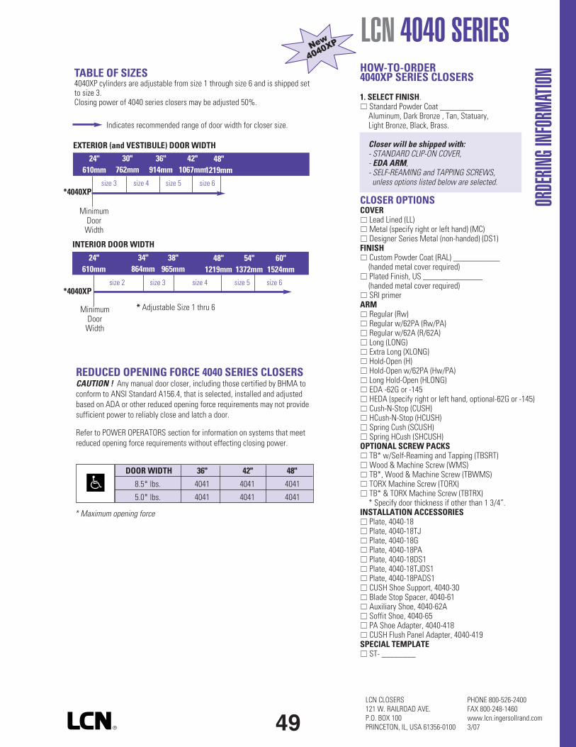
HOW-TO-ORDER4040XP SERIES CLOSERS
1. SELECT FINISH.Standard Powder Coat __________Aluminum, Dark Bronze , Tan, Statuary,Light Bronze, Black, Brass.
Closer will be shipped with:- STANDARD CLIP-ON COVER,- EDA ARM,- SELF-REAMING and TAPPING SCREWS,unless options listed below are selected.
CLOSER OPTIONSCOVER
Lead Lined (LL)Metal (specify right or left hand) (MC)Designer Series Metal (non-handed) (DS1)
FINISHCustom Powder Coat (RAL) ___________(handed metal cover required)Plated Finish, US ______________(handed metal cover required)SRI primer
ARMRegular (Rw)Regular w/62PA (Rw/PA)Regular w/62A (R/62A)Long (LONG)Extra Long (XLONG)Hold-Open (H)Hold-Open w/62PA (Hw/PA)Long Hold-Open (HLONG)EDA -62G or -145HEDA (specify right or left hand, optional-62G or -145)Cush-N-Stop (CUSH)HCush-N-Stop (HCUSH)Spring Cush (SCUSH)Spring HCush (SHCUSH)
OPTIONAL SCREW PACKSTB* w/Self-Reaming and Tapping (TBSRT)Wood & Machine Screw (WMS)TB*, Wood & Machine Screw (TBWMS)TORX Machine Screw (TORX)TB* & TORX Machine Screw (TBTRX)* Specify door thickness if other than 1 3/4”.
INSTALLATION ACCESSORIESPlate, 4040-18Plate, 4040-18TJPlate, 4040-18GPlate, 4040-18PAPlate, 4040-18DS1Plate, 4040-18TJDS1Plate, 4040-18PADS1CUSH Shoe Support, 4040-30Blade Stop Spacer, 4040-61Auxiliary Shoe, 4040-62ASoffit Shoe, 4040-65PA Shoe Adapter, 4040-418CUSH Flush Panel Adapter, 4040-419
SPECIAL TEMPLATEST- ________
LCN CLOSERS121 W. RAILROAD AVE.P.O. BOX 100PRINCETON, IL, USA 61356-0100
PHONE 800-526-2400FAX 800-248-1460www.lcn.ingersollrand.com3/07
LCN 4040 SERIES
ORDE
RINGI
NFOR
MATIO
N
49
Indicates recommended range of door width for closer size.
TABLE OF SIZES4040XP cylinders are adjustable from size 1 through size 6 and is shipped setto size 3.Closing power of 4040 series closers may be adjusted 50%.
REDUCED OPENING FORCE 4040 SERIES CLOSERSCAUTION ! Any manual door closer, including those certified by BHMA toconform to ANSI Standard A156.4, that is selected, installed and adjustedbased on ADA or other reduced opening force requirements may not providesufficient power to reliably close and latch a door.
Refer to POWER OPERATORS section for information on systems that meetreduced opening force requirements without effecting closing power.
* Maximum opening force
size 3 size 4 size 5 size 6*4040XP
EXTERIOR (and VESTIBULE) DOOR WIDTH
24"610mm
30"762mm
36"914mm
42"1067mm
INTERIOR DOOR WIDTH
48"1219mm
24"610mm
34"864mm
38"965mm
48"1219mm
54"1372mm
60"1524mm
size 2 size 3 size 4 size 5 size 6*4040XP
* Adjustable Size 1 thru 6
DOOR WIDTH 36" 42" 48"
8.5* lbs. 4041 4041 4041
5.0* lbs. 4041 4041 4041
MinimumDoorWidth
MinimumDoorWidth

OverviewAD-Series electronic locks from Schlage are designed to be modular and provide more options to choose from, more functionality in the lock and more compatibility with existing systems. Its patent-pending modular design allows the lock to be customized to fit the needs of an application now, and can change to meet future needs without removing it from the door.
Factory orderable options include choices of credential readers, chassis type, network configurations, locking functions, lever styles and finishes. It also offers a wide selection of features that can be configured in the field to customize your openings.
To simplify installation, the AD-Series combines all the hardware components required at the door for a complete access control system into one integrated design that includes the electrified lock, credential reader, request-to-exit and -enter sensors, door position switch, tamper switch and more.
The AD-300 has a number of features built in that are configurable in the field and a long list of items that can be monitored by access control software. Please consult your access control software partner for details on the integration of specific features.
AD-300 Networked Hardwired Electronic Lock
Features and Benefits
• Open Architecture platform • Panel interface options ensure seamless communication
with your system• Real-time communication between access control
system and lock• Field configurable Fail Safe/Fail Secure and other
capabilities per code• Available in cylindrical, mortise, mortise with deadbolt
and exit trim • Compatible with major brands of master key systems• A wide selection of credential readers and networking
options to choose from• AD-Series with multi-technology readers are NFC
compatible• ANSI/BHMA A156.25, ANSI/BHMA Grade 1, UL 294,
UL10C, FCC Part 15, ADA, RoHS
Net
wor
ked
Lock
ing
Solu
tion
s
AD
-300
Har
dwire
d

Panel Interface Board (PIB300-2D)If the system requires Wiegand or Clock & Data protocol (rather than a direct RS-485 connection), the AD-Series open architecture platform connects up to two AD-300 locks to the Panel Interface Board (PIB300 - sold separately, if required) that seamlessly connects to an access control panel or reader interface board. All monitoring is captured at the remote monitoring station.
Functions Classroom/Storeroom Office* Privacy*
Apartment*Note: BHMA/ANSI functions such as these can be implemented by the Software when Door Position, Deadbolt Position and/or Interior Push button are monitored. Consult Software provider for specific capabilities. Classroom/Storeroom and Office function not available with Mortise Deadbolt option.
Available Status Signals Lock/Unlock Status†
Request-to-Exit
Door Position
Mechanical Key Override*
Deadbolt Position*
Interior Cover Tamper Guard* Communication Status*
Interior Push Button*
Request-to-Enter* * Consult your access control software provider for specific scope of support. Interior pushbutton, mechanical key override and deadbolt position are only available when linked via PIM400-485.
< 1 secondCredential Verification Time
RS-485 : 9.6 kbpsData Rate
Tri-colored LED’s & audible indicators (field configurable)Visual/Audible Communications
Wiegand or Clock & Data via PIB300, or RS-485 directlySystem Interface
4 VDC to 26 VDCVoltage Range
12 VDC or 24 VDCPower Supply
Up to 250 mAMax Current Requirement
18AWG, 2 Conductor (Belden 8760 or equivalent)Cable Specifications for Power
AD-300 to Power Supply: up to 1000 ft (303 m)Cable Distance for Power
24AWG, 2 or 4 Conductor Shielded (Belden 9841, 9842 or equivalent)Cable Specifications for Data
0 - 100% condensingOperating Humidity
ANSI/BHMA A156.25, ANSI/BHMA Grade 1, UL 294, UL10 C, FCC Part 15, ADA, RoHSCertifications
Panel Interface Board (PIB300), Handheld Device (HHD), Dry Contact Relay Board (RLBD) may be required for supervised inputs (Wiegand systems)
Accessories
AD-300 Electronic Lock Specifications
Communication Range
13 LEDs for Status IndicatorsVisual/Audible
Wiegand or Clock & DataSystem Interface
9.5 VDC to 26 VDCVoltage Range
12 VDC or 24 VDCPower Supply
Up to 250 mAMax Current Requirements
-31° to 151°F (-35° to 66°C)Operating Temperature
7.1” x 7.1” x 3.0” (18.0 cm x 18.0 cm x 7.6 cm)
Dimensions (HWD)
1.25 lb (.57 kg)Weight
22AWG, 8 Conductor Shielded (Alpha 1298C or equivalent)
Cable Specifications(PIB300 to ACP)
NEMA 1, 4, 4X, 6; UL 294, FCC Part 15; RoHSCertifications
PIB300-2D Specifications
PIB300 to Lock, RS-485: up to 4000’
PIB300 to ACP, Wiegand or Clock & Data: up to 500’
Dimensions
System Configuration
ACCESS CONTROL PANEL (ACP)
Directly communicates via RS-485
RS-485
AD-300
Wiegand or Clock & Data
PANEL INTERFACEBOARD (PIB300-2D)
AD-300
ACCESS CONTROL MANAgEMENT SySTEM
AD-300 to PIB300 or ACP, RS-485: up to 4000 ft (1219 m)Cabling Distance for Data
-31° to 151°F (-35° to 66°C)Operating Temperature
† Software indicates lock/unlock status based on sequence of events, but cannot validate mechanical clutch positions unless monitored on RS-485* connection
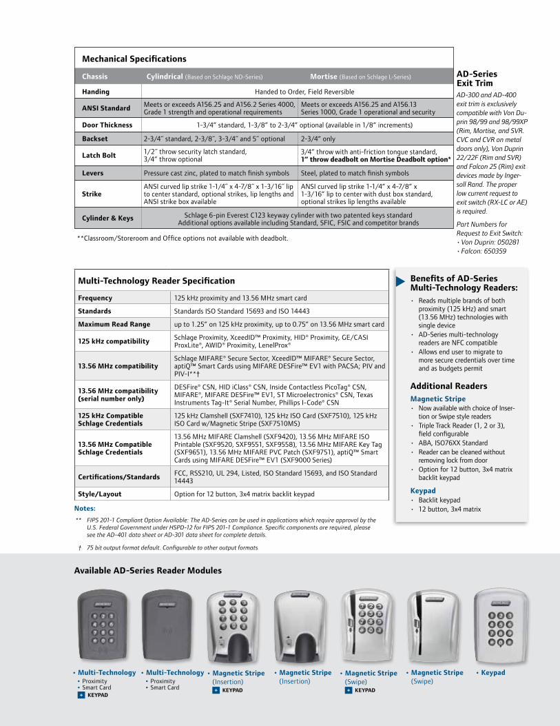
AD-300 and AD-400 exit trim is exclusively compatible with Von Du-prin 98/99 and 98/99XP (Rim, Mortise, and SVR. CVC and CVR on metal doors only), Von Duprin 22/22F (Rim and SVR) and Falcon 25 (Rim) exit devices made by Inger-soll Rand. The proper low current request to exit switch (RX-LC or AE) is required. Part Numbers for Request to Exit Switch:• Von Duprin: 050281• Falcon: 650359
AD-Series Exit Trim
Mechanical Specifications
Handing
Chassis Cylindrical (Based on Schlage ND-Series)
Meets or exceeds A156.25 and A156.2 Series 4000, Grade 1 strength and operational requirements
2-3/4˝ standard, 2-3/8˝, 3-3/4˝ and 5˝ optional
1/2˝ throw security latch standard, 3/4” throw optional
Pressure cast zinc, plated to match finish symbols
ANSI curved lip strike 1-1/4˝ x 4-7/8˝ x 1-3/16˝ lip to center standard, optional strikes, lip lengths and ANSI strike box available
Mortise (Based on Schlage L-Series)
Meets or exceeds A156.25 and A156.13 Series 1000, Grade 1 operational and security
2-3/4” only
Steel, plated to match finish symbols
ANSI curved lip strike 1-1/4” x 4-7/8” x 1-3/16” lip to center with dust box standard, optional strikes lip lengths available
ANSI Standard
Door Thickness
Backset
Latch Bolt
Levers
Strike
Cylinder & Keys
Handed to Order, Field Reversible
1-3/4” standard, 1-3/8” to 2-3/4” optional (available in 1/8” increments)
Schlage 6-pin Everest C123 keyway cylinder with two patented keys standard Additional options available including Standard, SFIC, FSIC and competitor brands
3/4” throw with anti-friction tongue standard, 1” throw deadbolt on Mortise Deadbolt option*
**Classroom/Storeroom and Office options not available with deadbolt.
Notes:
** FIPS 201-1 Compliant Option Available: The AD-Series can be used in applications which require approval by the U.S. Federal Government under HSPD-12 for FIPS 201-1 Compliance. Specific components are required, please see the AD-401 data sheet or AD-301 data sheet for complete details.
† 75 bit output format default. Configurable to other output formats
Benefits of AD-Series Multi-Technology Readers:• Reads multiple brands of both
proximity (125 kHz) and smart (13.56 MHz) technologies with single device
• AD-Series multi-technology readers are NFC compatible
• Allows end user to migrate to more secure credentials over time and as budgets permit
Additional Readers Magnetic Stripe• Now available with choice of Inser-
tion or Swipe style readers• Triple Track Reader (1, 2 or 3),
field configurable• ABA, ISO76XX Standard• Reader can be cleaned without
removing lock from door• Option for 12 button, 3x4 matrix
backlit keypad
Keypad• Backlit keypad • 12 button, 3x4 matrix
Multi-Technology Reader Specification
Frequency 125 kHz proximity and 13.56 MHz smart card
Standards Standards ISO Standard 15693 and ISO 14443
Maximum Read Range up to 1.25” on 125 kHz proximity, up to 0.75” on 13.56 MHz smart card
125 kHz compatibility Schlage Proximity, XceedID™ Proximity, HID® Proximity, GE/CASI ProxLite®, AWID® Proximity, LenelProx®
13.56 MHz compatibilitySchlage MIFARE® Secure Sector, XceedID™ MIFARE® Secure Sector, aptiQ™ Smart Cards using MIFARE DESFire™ EV1 with PACSA; PIV and PIV-I**†
13.56 MHz compatibility (serial number only)
DESFire® CSN, HID iClass® CSN, Inside Contactless PicoTag® CSN, MIFARE®, MIFARE DESFire™ EV1, ST Microelectronics® CSN, Texas Instruments Tag-It® Serial Number, Phillips I-Code® CSN
125 kHz Compatible Schlage Credentials
125 kHz Clamshell (SXF7410), 125 kHz ISO Card (SXF7510), 125 kHz ISO Card w/Magnetic Stripe (SXF7510MS)
13.56 MHz Compatible Schlage Credentials
13.56 MHz MIFARE Clamshell (SXF9420), 13.56 MHz MIFARE ISO Printable (SXF9520, SXF9551, SXF9558), 13.56 MHz MIFARE Key Tag (SXF9651), 13.56 MHz MIFARE PVC Patch (SXF9751), aptiQ™ Smart Cards using MIFARE DESFire™ EV1 (SXF9000 Series)
Certifications/Standards FCC, RSS210, UL 294, Listed, ISO Standard 15693, and ISO Standard 14443
Style/Layout Option for 12 button, 3x4 matrix backlit keypad
Available AD-Series Reader Modules
• Magnetic Stripe (Swipe)
• Magnetic Stripe (Swipe)
KEyPAD+
• Magnetic Stripe (Insertion)
• Keypad• Multi-Technology • Proximity • Smart Card
• Multi-Technology • Proximity • Smart Card
KEyPAD+
• Magnetic Stripe (Insertion)
KEyPAD+

877-671-7011 • securitytechnologies.ingersollrand.com
Selections Correspond With the Numbers Above
Lever styles
Sparta Rhodes
Athens Tubular
Warm tone finishes
Cool tone finishes
605 606 612 643eBright Brass Satin Brass Satin Bronze Aged Bronze
619 625 626 626AMSatin Nickel Bright Satin Chrome Satin Chrome Chrome with Antimicrobial
©2012 Ingersoll Rand 004448 06/12
Standard options are indicated in bold. See price book for specific configuration options.
10 HandingRH Right Handed LH Left HandedField reversible
11 Backset & Latch or Armor FrontCylindrical13-049 2-3/4” Backset, Deadlatch,
Square Corner, 1-1/8” x 2-1/4” Mortise 09-663 Armor Front, 1-1/4” Wide,
Square CornerSee price book for mortise deadbolt and other backset and latch options or armor front options
12 StrikeCylindrical 10-025 1-3/16 Lip, ANSI, No Box,
1-1/4” x 4-7/8” Mortise 10-072 1-3/16” Lip, 1-1/4” x 4-7/8”
Square Corner, Box See price book for other available strikes
13 Door Thickness1-3/4”Other thicknesses available between 1-3/8” and 2-3/4 See price book for detail.
6 LeverSPA SpartaRHO RhodesATH AthensTLR TubularAvailable with knurled surface
7 Finish626 Satin Chrome605 Bright Brass606 Satin Brass612 Satin Bronze619 Satin Nickel625 Bright Chrome643e Aged Bronze626AM Satin Chrome Antimicrobial
8 Lever Cylinder TypePD Schlage 6-pin Full CylinderSee price book for other SFIC, FSIC and Less Cores options available. Compatible with Schlage, Sargent, Corbin, Medeco and Yale
9 Keyway TypeC123 Everest See price book for other available keyway options including master keying
3 ChassisCY CylindricalMS MortiseMD Mortise Deadbolt993R Exit Trim – Rim/CVR/CVC993S Exit Trim – SVR993M Exit Trim – Mortise993DT Non-Functioning Dummy Trim for Exit
4 Function70 Classroom/Storeroom50 Office40 Privacy60 ApartmentLock function capabilities are determined by users access control system
5 ReaderKP KeypadMG Magnetic Stripe (Insertion)MGK Magnetic Stripe + Keypad
(Insertion)MS Magnetic Stripe (Swipe)MSK Magnetic Stripe + Keypad (Swipe)MT Multi-Technology (125 kHz and 13.56 MHz)MTK Multi-Technology + Keypad (125 kHz and 13.56 MHz)DT Dummy Trim
Standard cylinders shown, SFIC and FSIC also available.
INGERSOLL RAND, the Ingersoll Rand logo, SCHLAGE, the SCHLAGE logo, XceedID, Von Duprin, Falcon and aptiQ are trademarks of Ingersoll-Rand plc, its subsidiaries and/or affiliates in the United States and other countries. Inside PicoTag is a trademark of Inside Technologies. GE, CASI and ProxLite are trademarks of General Electric Corporation. MIFARE and MIFARE DESFire EV1 are trademarks of NXP B.V. HID and iCLASS are trademarks of HID Corporation. Tag-It is a trademark of Texas Instruments. STMicroelectronics is a trademark of STMicroelectronics Inc. Infineon and my-d are trademarks of Infineon Technologies. AWID is a trademark of Applied Wireless Identifications Group. All other trademarks are the property of their respective owners.
AD-300-CY-70-MG - SPA -626-PD-C123 -RH - 13-049-10-025-1-3/4Se
ries
Cla
ss
Ch
assi
s
Fun
ctio
n
Rea
der
Leve
r St
yle
Fin
ish
Leve
r C
ylin
der
Key
ing
Typ
e
Han
din
g
Stri
ke
Doo
r T
hic
knes
s
Bac
kset
&
Lat
ch
3 41 2 5 6 7 8 9 10 11 12 13
Ordering InformationAvailable through one of our GSA Schedule 84 approved distributors; BAA Options Available
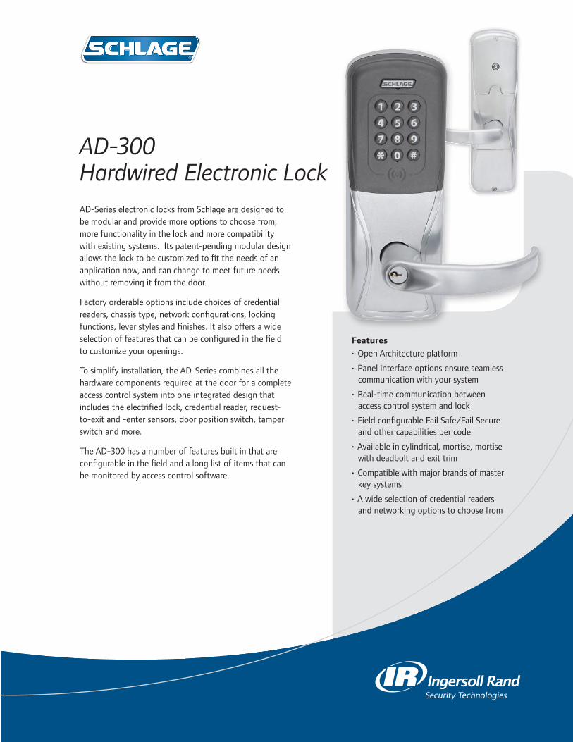
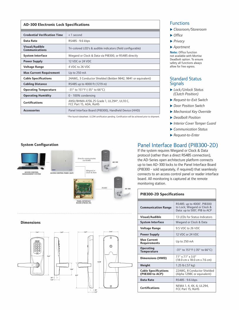
u
u
u
u
u
u
u
u
u
u
u
u
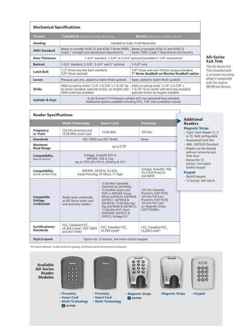
u


The AD-Series Electronic Lock is available in 993 Exit Trim for use on openings that require exit devices for either retrofit or new construction applications. Offline and networked solutions are available.
The 993 Exit Trim was designed to suite with AD-Series cylindrical and mortise locksets to ensure that the facility remains aesthetically consistent.
The AD-Series 993 Exit Trim utilizes universal hardware to simplify installation of offline trim to a variety of exit devices, including Rim style from Von Duprin, Falcon, Sargent, Corbin Russwin, Dorma, and Yale.
Available Exit Trim Styles:
• 993R – Rim or Concealed Vertical Rod (CVR for metal doors only)
• 993S – Surface Vertical Rod
• 993M – Mortise
Note: The AD-300 and AD-400 Exit Trim are exclusively compatible with the Von Duprin 98/99 exit devices utilizing a low current request-to-exit switch (LC-RX).
AD-Series Exit Trim Compatibility
Features
• Multiple Credential Reader Options
• Offline and Networked Communication Options
• A wide variety of finishes and lever styles
• Power options that include hardwired (12 VDC or 24 VDC) or batteries (4AA or 8AA)
• Compatible with most Standard, FSIC or SFIC keyways from major brands of master key systems including Schlage, Sargent, Corbin, Medeco and Yale
Compatibility
Devices AD-200/250 AD-300 AD-400
Von Duprin 98/99X X X
Rim/SVR/CVR/Mortise
Von Duprin 22/22F Rim/SVR X
Falcon 25 Rim/SVR X
Sargent 80 Rim X
Precision 21 Rim2100 converts to 21 with XPrecision’s BP21 kit
Yale 7000 Rim X
Corbin Russwin 5000 Rim X
Dorma 9300 Rim X

©2010 Ingersoll-Rand Company ES-5537 01/10860-584-9158 / 866-322-1237 • schlage.com
DIMENSIONS
ExteriorView
AD-Series - 993 Exit Trim
InteriorView
AD-200/250/300 - all styles
InteriorView
AD-400 all styles
SideView
AD-200/250/300 - RIM/CVR or Mortise
SideView
AD-400 RIM/CVR or Mortise
SideView
AD-200/250/300 SVR
SideView
AD-400 SVR
AvailableAD-SeriesReaderModules• Proximity (125 kHz)
• Smart Card (13.56 MHz)
• Multi-Technology (125 kHz proximity and 13.56 MHz smart card)
• Magnetic Stripe
• Keypad Only
• All credential readers available + Keypad
* unlike other AD-Series chassis styles, upgrading reader modules on the 993 Exit Trim requires the exterior escutcheon to be removed from the door
AvailableCommunicationOptions• AD-400: Networked Wireless Locks
• AD-300: Networked Hardwired Locks
• AD-250: Offline, access rights stored on the magnetic stripe credential
• AD-200: Offline, access rights stored on the lock
ProfileView
* AD-300 includes LED indicatorNote: (2) #7 fasteners with decorative washers located 11.88” below bottom edge of lock

The AD-Series Electronic Lock is available in 993 Exit Trim for use on openings that require exit devices for either retrofit or new construction applications. Offline and networked solutions are available.
The 993 Exit Trim was designed to suite with AD-Series cylindrical and mortise locksets to ensure that the facility remains aesthetically consistent.
The AD-Series 993 Exit Trim utilizes universal hardware to simplify installation of offline trim to a variety of exit devices, including Rim style from Von Duprin, Falcon, Sargent, Corbin Russwin, Dorma, and Yale.
Available Exit Trim Styles:
• 993R – Rim or Concealed Vertical Rod (CVR for metal doors only)
• 993S – Surface Vertical Rod
• 993M – Mortise
Note: The AD-300 and AD-400 Exit Trim are exclusively compatible with the Von Duprin 98/99 exit devices utilizing a low current request-to-exit switch (LC-RX).
AD-Series Exit Trim Compatibility
Features
• Multiple Credential Reader Options
• Offline and Networked Communication Options
• A wide variety of finishes and lever styles
• Power options that include hardwired (12 VDC or 24 VDC) or batteries (4AA or 8AA)
• Compatible with most Standard, FSIC or SFIC keyways from major brands of master key systems including Schlage, Sargent, Corbin, Medeco and Yale
Compatibility
Devices AD-200/250 AD-300 AD-400
Von Duprin 98/99X X X
Rim/SVR/CVR/Mortise
Von Duprin 22/22F Rim/SVR X
Falcon 25 Rim/SVR X
Sargent 80 Rim X
Precision 21 Rim2100 converts to 21 with XPrecision’s BP21 kit
Yale 7000 Rim X
Corbin Russwin 5000 Rim X
Dorma 9300 Rim X
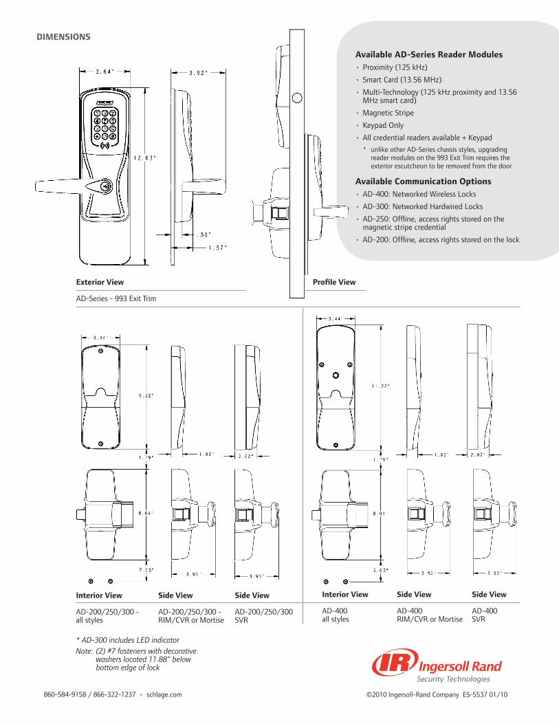
©2010 Ingersoll-Rand Company ES-5537 01/10860-584-9158 / 866-322-1237 • schlage.com
DIMENSIONS
ExteriorView
AD-Series - 993 Exit Trim
InteriorView
AD-200/250/300 - all styles
InteriorView
AD-400 all styles
SideView
AD-200/250/300 - RIM/CVR or Mortise
SideView
AD-400 RIM/CVR or Mortise
SideView
AD-200/250/300 SVR
SideView
AD-400 SVR
AvailableAD-SeriesReaderModules• Proximity (125 kHz)
• Smart Card (13.56 MHz)
• Multi-Technology (125 kHz proximity and 13.56 MHz smart card)
• Magnetic Stripe
• Keypad Only
• All credential readers available + Keypad
* unlike other AD-Series chassis styles, upgrading reader modules on the 993 Exit Trim requires the exterior escutcheon to be removed from the door
AvailableCommunicationOptions• AD-400: Networked Wireless Locks
• AD-300: Networked Hardwired Locks
• AD-250: Offline, access rights stored on the magnetic stripe credential
• AD-200: Offline, access rights stored on the lock
ProfileView
* AD-300 includes LED indicatorNote: (2) #7 fasteners with decorative washers located 11.88” below bottom edge of lock


u
u
u
u
u
u
u
u
u
u
u
u

u


The AD-Series Electronic Lock is available in 993 Exit Trim for use on openings that require exit devices for either retrofit or new construction applications. Offline and networked solutions are available.
The 993 Exit Trim was designed to suite with AD-Series cylindrical and mortise locksets to ensure that the facility remains aesthetically consistent.
The AD-Series 993 Exit Trim utilizes universal hardware to simplify installation of offline trim to a variety of exit devices, including Rim style from Von Duprin, Falcon, Sargent, Corbin Russwin, Dorma, and Yale.
Available Exit Trim Styles:
• 993R – Rim or Concealed Vertical Rod (CVR for metal doors only)
• 993S – Surface Vertical Rod
• 993M – Mortise
Note: The AD-300 and AD-400 Exit Trim are exclusively compatible with the Von Duprin 98/99 exit devices utilizing a low current request-to-exit switch (LC-RX).
AD-Series Exit Trim Compatibility
Features
• Multiple Credential Reader Options
• Offline and Networked Communication Options
• A wide variety of finishes and lever styles
• Power options that include hardwired (12 VDC or 24 VDC) or batteries (4AA or 8AA)
• Compatible with most Standard, FSIC or SFIC keyways from major brands of master key systems including Schlage, Sargent, Corbin, Medeco and Yale
Compatibility
Devices AD-200/250 AD-300 AD-400
Von Duprin 98/99X X X
Rim/SVR/CVR/Mortise
Von Duprin 22/22F Rim/SVR X
Falcon 25 Rim/SVR X
Sargent 80 Rim X
Precision 21 Rim2100 converts to 21 with XPrecision’s BP21 kit
Yale 7000 Rim X
Corbin Russwin 5000 Rim X
Dorma 9300 Rim X

©2010 Ingersoll-Rand Company ES-5537 01/10860-584-9158 / 866-322-1237 • schlage.com
DIMENSIONS
ExteriorView
AD-Series - 993 Exit Trim
InteriorView
AD-200/250/300 - all styles
InteriorView
AD-400 all styles
SideView
AD-200/250/300 - RIM/CVR or Mortise
SideView
AD-400 RIM/CVR or Mortise
SideView
AD-200/250/300 SVR
SideView
AD-400 SVR
AvailableAD-SeriesReaderModules• Proximity (125 kHz)
• Smart Card (13.56 MHz)
• Multi-Technology (125 kHz proximity and 13.56 MHz smart card)
• Magnetic Stripe
• Keypad Only
• All credential readers available + Keypad
* unlike other AD-Series chassis styles, upgrading reader modules on the 993 Exit Trim requires the exterior escutcheon to be removed from the door
AvailableCommunicationOptions• AD-400: Networked Wireless Locks
• AD-300: Networked Hardwired Locks
• AD-250: Offline, access rights stored on the magnetic stripe credential
• AD-200: Offline, access rights stored on the lock
ProfileView
* AD-300 includes LED indicatorNote: (2) #7 fasteners with decorative washers located 11.88” below bottom edge of lock
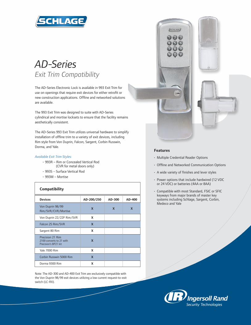

Features
• 2A@12/24VDCoutput,fieldselectablewithjumper
• Class2Ratedpowerlimitedoutput
• Universal120-240VACinput
• LowvoltageDC,regulatedandfiltered
• Singlepolarizedconnectorfordistributionboard
• Fusedprimaryinput
• ACinputandDCoutputmonitoringcircuitw/LEDindicators
• CovermountedACinputindication
• NEMA1enclosure
• Hingedcoverw/lockdownscrews
• Highvoltageprotectivecover
OverviewSchlage’scomprehensivelineofpowersuppliesandoptionboardsweredesignedtoaddressthechangingneedsoftheaccesscontrolmarket.
Installationissimplifiedbyutilizingaflatmountingdesignandpolarizedlockingconnectorsforoptionboards.Thisnewdesigneliminatestheneedforracksandsideconnectors.Theflatmountingoftheoptionboardsalsoprovidesforeasieraccesstotheterminalblocksforconnectionofelectrifieddevices(suchaselectrifiedstrikes,electromagneticlocks,cardreaders,etc).
CommontothelineofPS900Seriespowersuppliesisaconstantoutputratingatboth12vand24vsettings,universal120VACto240VACinput,andpolarizedoptionboardconnectors.Newfirealarminterfaceboardmountingallowsoutputstobeconfiguredasswitched(powercut)orunswitched(powercontinues)whensignalprovided.
*AllPS900SeriesofpowersuppliesandoptionboardshavebeentestedandcertifiedtomeetUL294.
PS9022 amp Power Supply
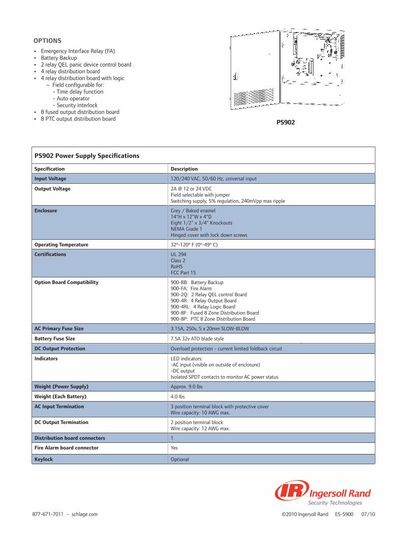
©2010IngersollRandES-590007/10877-671-7011•schlage.com
PS902 Power Supply Specifications
Specification Description
Input Voltage 120/240VAC,50/60Hz,universalinput
Output Voltage 2A@12or24VDCFieldselectablewithjumperSwitchingsupply,5%regulation,240mVppmaxripple
Enclosure Grey/Bakedenamel14"Hx12"Wx4"DEight1/2"x3/4"KnockoutsNEMAGrade1Hingedcoverwithlockdownscrews
Operating Temperature 32º-120ºF(0º-49ºC)
Certifications UL294Class2RoHSFCCPart15
Option Board Compatibility 900-BB:BatteryBackup900-FA:FireAlarm900-2Q:2RelayQELcontrolBoard900-4R:4RelayOutputBoard900-4RL:4RelayLogicBoard900-8F:Fused8ZoneDistributionBoard900-8P:PTC8ZoneDistributionBoard
AC Primary Fuse Size 3.15A,250v,5x20mmSLOW-BLOW
Battery Fuse Size 7.5A32vATObladestyle
DC Output Protection Overloadprotection-currentlimitedfoldbackcircuit
Indicators LEDindicators:-ACinput(visibleonoutsideofenclosure)-DCoutputIsolatedSPDTcontactstomonitorACpowerstatus
Weight (Power Supply) Approx.9.0lbs
Weight (Each Battery) 4.0lbs
AC Input Termination 3positionterminalblockwithprotectivecoverWirecapacity:10AWGmax.
DC Output Termination 2positionterminalblockWirecapacity:12AWGmax.
Distribution board connectors 1
Fire Alarm board connector Yes
Keylock Optional
OPTIONS
• EmergencyInterfaceRelay(FA)• BatteryBackup• 2relayQELpanicdevicecontrolboard• 4relaydistributionboard• 4relaydistributionboardwithlogic – Fieldconfigurablefor: •Timedelayfunction •Autooperator •Securityinterlock• 8fusedoutputdistributionboard• 8PTCoutputdistributionboard
PS902
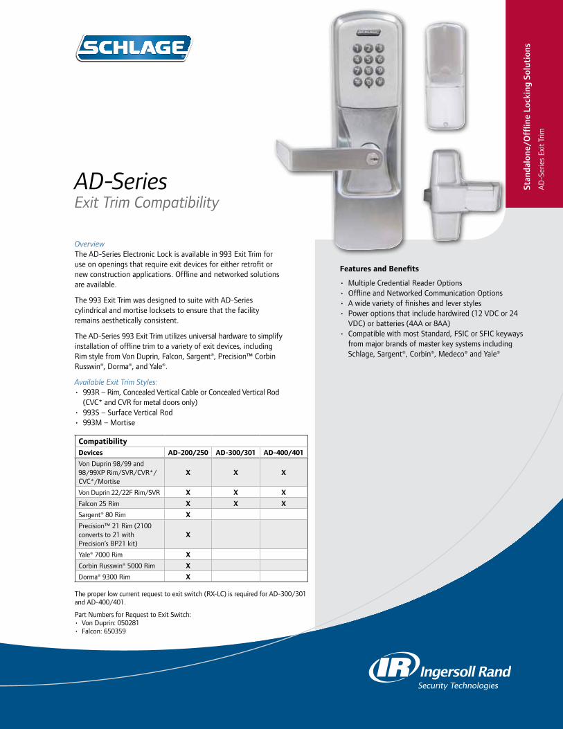
OverviewThe AD-Series Electronic Lock is available in 993 Exit Trim for use on openings that require exit devices for either retrofit or new construction applications. Offline and networked solutions are available.
The 993 Exit Trim was designed to suite with AD-Series cylindrical and mortise locksets to ensure that the facility remains aesthetically consistent.
The AD-Series 993 Exit Trim utilizes universal hardware to simplify installation of offline trim to a variety of exit devices, including Rim style from Von Duprin, Falcon, Sargent®, Precision™ Corbin Russwin®, Dorma®, and Yale®.
Available Exit Trim Styles:• 993R – Rim, Concealed Vertical Cable or Concealed Vertical Rod
(CVC* and CVR for metal doors only)• 993S – Surface Vertical Rod• 993M – Mortise
The proper low current request to exit switch (RX-LC) is required for AD-300/301 and AD-400/401.
Part Numbers for Request to Exit Switch:• Von Duprin: 050281• Falcon: 650359
AD-Series Exit Trim Compatibility
Features and Benefits
• Multiple Credential Reader Options • Offline and Networked Communication Options • A wide variety of finishes and lever styles• Power options that include hardwired (12 VDC or 24
VDC) or batteries (4AA or 8AA)• Compatible with most Standard, FSIC or SFIC keyways
from major brands of master key systems including Schlage, Sargent®, Corbin®, Medeco® and Yale®
CompatibilityDevices AD-200/250 AD-300/301 AD-400/401
Von Duprin 98/99 and 98/99XP Rim/SVR/CVR*/CVC*/Mortise
X X X
Von Duprin 22/22F Rim/SVR X X X
Falcon 25 Rim X X X
Sargent® 80 Rim X
Precision™ 21 Rim (2100 converts to 21 with Precision’s BP21 kit)
X
Yale® 7000 Rim X
Corbin Russwin® 5000 Rim X
Dorma® 9300 Rim X
Stan
dalo
ne/O
fflin
e Lo
ckin
g So
luti
ons
AD
-Ser
ies
Exit
Trim
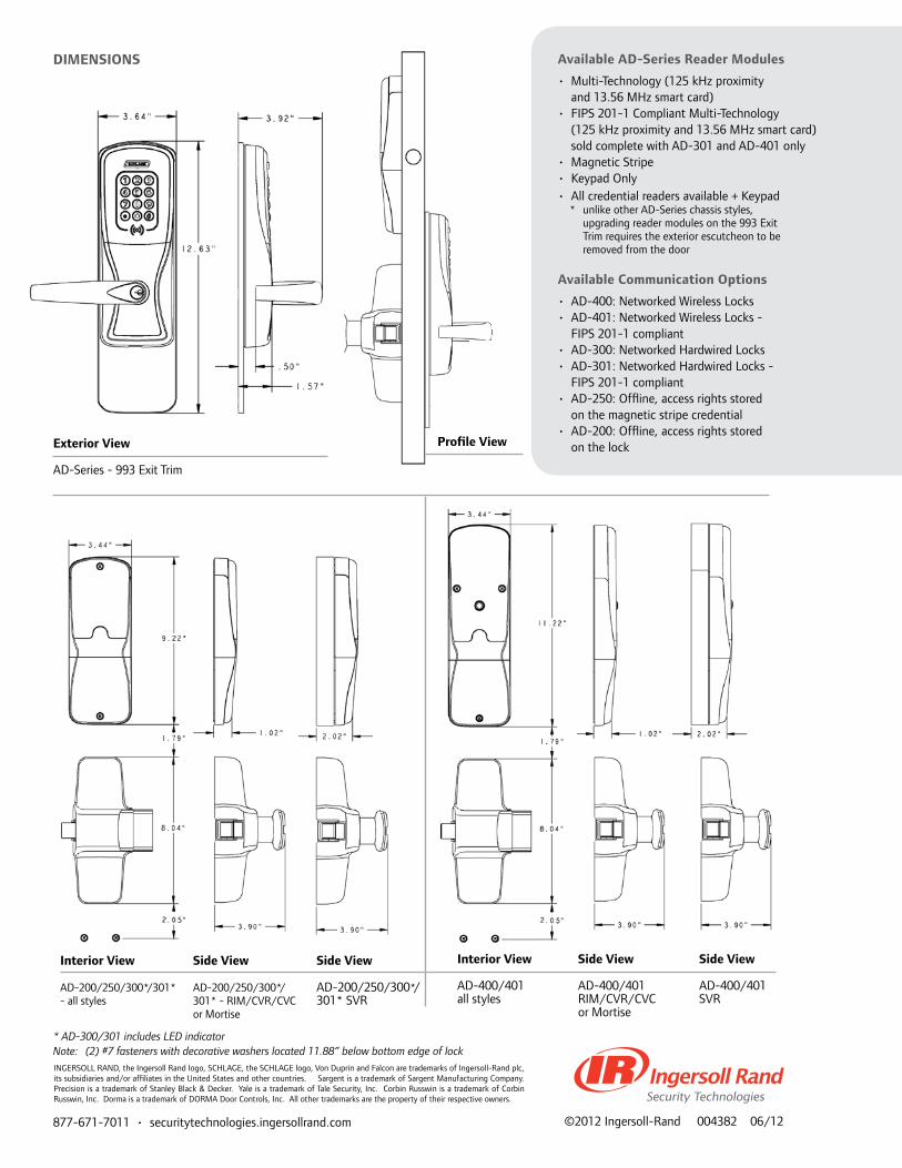
877-671-7011 • securitytechnologies.ingersollrand.com ©2012 Ingersoll-Rand 004382 06/12
Dimensions
exterior View
AD-Series - 993 Exit Trim
interior View
AD-200/250/300*/301* - all styles
interior View
AD-400/401 all styles
side View
AD-200/250/300*/ 301* - RIM/CVR/CVC or Mortise
side View
AD-400/401 RIM/CVR/CVC or Mortise
side View
AD-200/250/300*/ 301* SVR
side View
AD-400/401 SVR
Available AD-series Reader modules
• Multi-Technology (125 kHz proximity and 13.56 MHz smart card)
• FIPS 201-1 Compliant Multi-Technology (125 kHz proximity and 13.56 MHz smart card) sold complete with AD-301 and AD-401 only
• Magnetic Stripe • Keypad Only • All credential readers available + Keypad * unlike other AD-Series chassis styles,
upgrading reader modules on the 993 Exit Trim requires the exterior escutcheon to be removed from the door
Available Communication options
• AD-400: Networked Wireless Locks• AD-401: Networked Wireless Locks -
FIPS 201-1 compliant • AD-300: Networked Hardwired Locks• AD-301: Networked Hardwired Locks -
FIPS 201-1 compliant • AD-250: Offline, access rights stored
on the magnetic stripe credential• AD-200: Offline, access rights stored
on the lockProfile View
* AD-300/301 includes LED indicatorNote: (2) #7 fasteners with decorative washers located 11.88” below bottom edge of lockINGERSOLL RAND, the Ingersoll Rand logo, SCHLAGE, the SCHLAGE logo, Von Duprin and Falcon are trademarks of Ingersoll-Rand plc, its subsidiaries and/or affiliates in the United States and other countries. Sargent is a trademark of Sargent Manufacturing Company. Precision is a trademark of Stanley Black & Decker. Yale is a trademark of Tale Security, Inc. Corbin Russwin is a trademark of Corbin Russwin, Inc. Dorma is a trademark of DORMA Door Controls, Inc. All other trademarks are the property of their respective owners.

Security Management System
Model SMR10 and SMR20Mercury Magnetic Stripe Readers
FEATURES & BENEFITS• Rugged Metal Housing
• All stainless steel hardware is standard
• Audiovisual indication provides Two LED’s(red/green) and beeper sounds
• Static Discharge Protection
• Accepts low or high coercivity-magnetic cards
• Standard Track 2 encoding (Track 1 & 3 areavailable)
• One security screw mounting
• Supports Wiegand or Clock & Data interfaceformats via Dip Switches
Overview
The SMR10 Mercury Magnetic Stripe Reader has a slim, mullionstyle design. The die cast metal housing makes it ideal forindoor or outdoor applications.
The SMR20 Mercury Magnetic Stripe Reader has a slim,mullion style design. The die cast metal housingmakes it ideal for indoor or outdoor applications.The keypad is a 12 position membrane style.
SPECIFICATIONS:• Dimensions: 1.95"W x 1.3"H x 5.5"L• Power requirements: 5 or 12 VDC• Power consumption 20 mA at 12 VDC• Operating temperature: -40F to 170F• Weight: 10 oz.• Cable distance: 500' with 18AWG 6 conductor
stranded with overall shield
ORDERING INFORMATION:SMR10 - 5VDC Magnetic Stripe Card Reader(specify black or beige)
SMR10-12V - 12VDC Magnetic Stripe Card Reader(specify black or beige)
SMR20 - 5VDC Magnetic Stripe Card Reader w/keypad (specify black or beige)
SMR20-12V - 12VDC Magnetic Stripe Card Readerw/ keypad (specify black or beige)

© 2006 Ingersoll-Rand Company Pub No. LK-5079 Rev. 6/06
SchlageElectronic Security575 Birch StreetForestville, CT 06010 USATel 860-584-9158/866-322-1237Fax 860-584-2136/866-322-1233Tel 800-950-4573 (Toll Free Canada)www.schlage.com
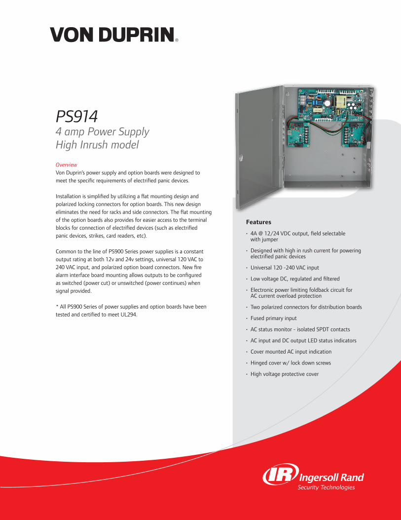
Features
• 4A@12/24VDCoutput,fieldselectablewithjumper
• Designedwithhighinrushcurrentforpoweringelectrifiedpanicdevices
• Universal120-240VACinput
• LowvoltageDC,regulatedandfiltered
• ElectronicpowerlimitingfoldbackcircuitforACcurrentoverloadprotection
• Twopolarizedconnectorsfordistributionboards
• Fusedprimaryinput
• ACstatusmonitor-isolatedSPDTcontacts
• ACinputandDCoutputLEDstatusindicators
• CovermountedACinputindication
• Hingedcoverw/lockdownscrews
• Highvoltageprotectivecover
OverviewVonDuprin’spowersupplyandoptionboardsweredesignedtomeetthespecificrequirementsofelectrifiedpanicdevices.
Installationissimplifiedbyutilizingaflatmountingdesignandpolarizedlockingconnectorsforoptionboards.Thisnewdesigneliminatestheneedforracksandsideconnectors.Theflatmountingoftheoptionboardsalsoprovidesforeasieraccesstotheterminalblocksforconnectionofelectrifieddevices(suchaselectrifiedpanicdevices,strikes,cardreaders,etc).
CommontothelineofPS900Seriespowersuppliesisaconstantoutputratingatboth12vand24vsettings,universal120VACto240VACinput,andpolarizedoptionboardconnectors.Newfirealarminterfaceboardmountingallowsoutputstobeconfiguredasswitched(powercut)orunswitched(powercontinues)whensignalprovided.
*AllPS900SeriesofpowersuppliesandoptionboardshavebeentestedandcertifiedtomeetUL294.
PS9144 amp Power SupplyHigh Inrush model
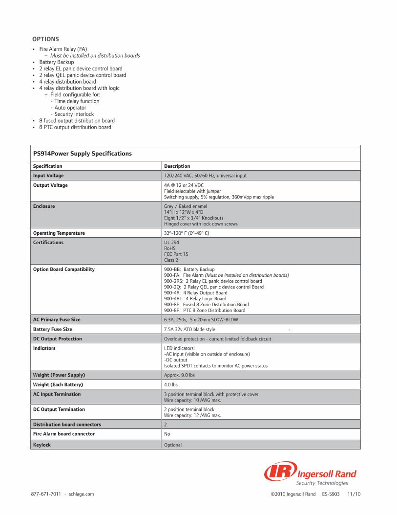
©2010IngersollRandES-590311/10877-671-7011•schlage.com
PS914Power Supply Specifications
Specification Description
Input Voltage 120/240VAC,50/60Hz,universalinput
Output Voltage 4A@12or24VDCFieldselectablewithjumperSwitchingsupply,5%regulation,360mVppmaxripple
Enclosure Grey/Bakedenamel14"Hx12"Wx4"DEight1/2"x3/4"KnockoutsHingedcoverwithlockdownscrews
Operating Temperature 32º-120ºF(0º-49ºC)
Certifications UL294RoHSFCCPart15Class2
Option Board Compatibility 900-BB:BatteryBackup900-FA:FireAlarm (Must be installed on distribution boards)900-2RS:2RelayELpanicdevicecontrolboard900-2Q:2RelayQELpanicdevicecontrolBoard900-4R:4RelayOutputBoard900-4RL:4RelayLogicBoard900-8F:Fused8ZoneDistributionBoard900-8P:PTC8ZoneDistributionBoard
AC Primary Fuse Size 6.3A,250v,5x20mmSLOW-BLOW
Battery Fuse Size 7.5A32vATObladestyle
DC Output Protection Overloadprotection-currentlimitedfoldbackcircuit
Indicators LEDindicators:-ACinput(visibleonoutsideofenclosure)-DCoutputIsolatedSPDTcontactstomonitorACpowerstatus
Weight (Power Supply) Approx.9.0lbs
Weight (Each Battery) 4.0lbs
AC Input Termination 3positionterminalblockwithprotectivecoverWirecapacity:10AWGmax.
DC Output Termination 2positionterminalblockWirecapacity:12AWGmax.
Distribution board connectors 2
Fire Alarm board connector No
Keylock Optional
OPTIONS
• FireAlarmRelay(FA) – Must be installed on distribution boards• BatteryBackup• 2relayELpanicdevicecontrolboard• 2relayQELpanicdevicecontrolboard• 4relaydistributionboard• 4relaydistributionboardwithlogic – Fieldconfigurablefor: •Timedelayfunction •Autooperator •Securityinterlock• 8fusedoutputdistributionboard• 8PTCoutputdistributionboard
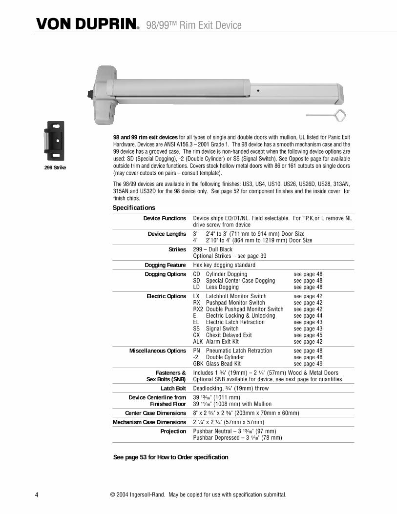
4 © 2004 Ingersoll-Rand. May be copied for use with specification submittal.
98/99™ Rim Exit Device
299 Strike
98 and 99 rim exit devices for all types of single and double doors with mullion, UL listed for Panic ExitHardware. Devices are ANSI A156.3 – 2001 Grade 1. The 98 device has a smooth mechanism case and the99 device has a grooved case. The rim device is non-handed except when the following device options areused: SD (Special Dogging), -2 (Double Cylinder) or SS (Signal Switch). See Opposite page for availableoutside trim and device functions. Covers stock hollow metal doors with 86 or 161 cutouts on single doors(may cover cutouts on pairs – consult template).
The 98/99 devices are available in the following finishes: US3, US4, US10, US26, US26D, US28, 313AN,315AN and US32D for the 98 device only. See page 52 for component finishes and the inside cover forfinish chips.
Specifications
Device Functions Device ships EO/DT/NL. Field selectable. For TP,K,or L remove NL drive screw from device
Device Lengths 3’ 2’4" to 3’ (711mm to 914 mm) Door Size4’ 2’10" to 4’ (864 mm to 1219 mm) Door Size
Strikes 299 – Dull BlackOptional Strikes – see page 39
Dogging Feature Hex key dogging standard
Dogging Options CD Cylinder Dogging see page 48 SD Special Center Case Dogging see page 48 LD Less Dogging see page 48
Electric Options LX Latchbolt Monitor Switch see page 42 RX Pushpad Monitor Switch see page 42 RX2 Double Pushpad Monitor Switch see page 42E Electric Locking & Unlocking see page 44EL Electric Latch Retraction see page 43 SS Signal Switch see page 43 CX Chexit Delayed Exit see page 45ALK Alarm Exit Kit see page 42
Miscellaneous Options PN Pneumatic Latch Retraction see page 48 -2 Double Cylinder see page 48 GBK Glass Bead Kit see page 49
Fasteners & Includes 1 ³�₄" (19mm) – 2 ¹�₄" (57mm) Wood & Metal DoorsSex Bolts (SNB) Optional SNB available for device, see next page for quantities
Latch Bolt Deadlocking, ³�₄" (19mm) throw
Device Centerline from 39 ¹³�₁₆" (1011 mm)Finished Floor 39 ¹¹�₁₆" (1008 mm) with Mullion
Center Case Dimensions 8" x 2 ³�₄" x 2 ³�₈" (203mm x 70mm x 60mm)
Mechanism Case Dimensions 2 ¹�₄" x 2 ¹�₄" (57mm x 57mm)
Projection Pushbar Neutral – 3 ¹³�₁₆" (97 mm)Pushbar Depressed – 3 ¹�₁₆" (78 mm)
See page 53 for How to Order specification

39
98/99™ Strike Information
Strikes for rim devices264 299 299F 499F
Projection 9/16" (14mm) Projection 13/16" (21mm) Projection 13/16" (21mm) Projection 15/16" (24mm)
1408 1439–Blade Stop 1410–Integral Stop
One per pair of doors Projection 1/2" (13mm) Projection 1/2" (13mm)
1606 1609
Projection 3/8" (10mm) • Requires CoordinatorPanic Devices Only • For Fire Rated Application, consult factory
Strikes for vertical rod devices248L-4 260U–Flush Transom Only 299 299F
Projection 3/8" (10mm) Projection 3/8" (10mm) Projection 13/16" (21mm) Projection 13/16" (21mm)For Fire Rated Application, consult factory
304L 338 385A 283
Mortise 13/16" (21mm) Mortise 5/8" (16mm) Mortise 2-1/2" (64mm) For use with WDC deviceswhen used with wood frames
Strikes for mortise lock devices575 575-2 576A 576B
• Not for use with astragals• Not for use on wood doors• Acceptable for 90 minute pair of hollow metal doors

98/99™ Rim Exit Device Standard Trim
5
Exit only Dummy Trim Night Latch Night LatchPull when Dogged Key Retracts Latchbolt Key Retracts Latchbolt
Optional Pull Required
Product Description
Trim Description
Escutcheon Plate Size
Pull Center to Center
Projection
ANSI Function
Cylinder Type
Optional Trim(See pages 32 – 34)
Optional #425 Sex Bolt Quantity for Device
98EO 98DT 98NL 98NL-OP99EO 99DT 99NL 99NL-OP
110NL-MD110NL-WD
3" x 14³�₁₆" x ³�₃₂" 3" x 14³�₁₆" x ³�₃₂"(76x360x2mm) (76x360x2mm)
–– 5¹�₂" (140mm) 5¹�₂" (140mm) ––
–– 2" (51mm) 2" (51mm) ––
01 02 03 03
–– –– Rim Rim
x990EO x991K-DT x991K-NLx992EO x992L-DT x992L-NLx994EO x994L-DT x994L-NLx996EO x996L-DT x996L-NL
x696DT x696NLx697DT x697NL
6 2 2 6
–– 990DT 990NL-R/V
–– ––
Lever Lever – Night Latch Lever – Blank Escutcheon Lever Dummy TrimKey Locks & Unlocks Key Retracts Latchbolt Always operable Pull when Dogged
(No Cylinder)
Product Description
Trim Description
Escutcheon Plate Size
Pull Center to Center
Projection
ANSI Function
Cylinder Type
Optional Trim(See pages 32 – 34)
Optional #425 Sex Bolt Quantity for Device
98L 98L-NL 98L-BE 98L-DT99L 99L-NL 99L-BE 99L-DT
996L-R/V 996L-NL-R/V 996L-BE-R/V 996L-DT-R/V
2³�₄" x 10³�₄" x ²⁷�₃₂" 2³�₄" x 10³�₄" x ²⁷�₃₂" 2³�₄" x 10³�₄" x ²⁷�₃₂" 2³�₄" x 10³�₄" x ²⁷�₃₂"(70x273x21mm) (70x273x21mm) (70x273x21mm) (70x273x21mm)
–– –– –– ––
2⁷�₈" (73mm) 2⁷�₈" (73mm) 2⁷�₈" (73mm) 2⁷�₈" (73mm)
08 09 –– 02
Rim Rim –– ––
x992L x992L-NL x992L-BE x992L-DTx994L x994L-NL x994L-BE x994L-DT
2 2 2 2
For optional trims and functions see pages 32-34

Signal Switch RX and LX
17
RX (request to exit) signal switch featureis used to signal the use of an openingfrom the push side. When the push padis depressed, the switch is activated.These devices are equipped with aninternal SPDT (single pole double throw)switch that monitors the touch bar.See Low Current option for computeroperated system applications.
RX2 (double request to exit) features 2 RX switches.
LX (latchbolt monitoring) signal switchmonitors both egress and access of anopening. When the latchbolt is retracted,the switch is activated. These devices areequipped with an internal SPDT (singlepole double throw) switch that monitorsthe latchbolt position. See Low Currentoption for computer operated systemapplications.
LC (low current) option is available forRX and LX switches. (Most commonlyused in computer operated monitoringsystems.) The RX2 is not available in lowcurrent.
Signal Switches are available on 22, 33A,35A, 55, 88, 98, 99 series devices. Thelow current version is not available withthe 55 and 88 series devices.
The INPACT 94/95 series devices areonly available with the LX switch option.
The device can be connected to a securityconsole, or may be used as a single dooralarm, when used with a horn and powersupply. A continuous current electrictransfer must be used for transferringthe signal from the frame to the door.
Signal Switches can be used in combinationwith other electrical functions (EL, E).
• RX or RX2 may be combined with the E(electric unlocking) mortise lock device.
• For latchbolt monitoring on a mortiselock device, specify a SS7500 lock.
• LX and RX switches can be combined.Example: LX-RX99L.
• LX, RX or RX2 switches can be used incombination with EL (electric latchretraction) option.
RX, RX2 and LX switches are availablefor factory or field installation.
RX and LX switches should not be usedto control a load, but as a signalingswitch.
Rim device shown — Refer to 33A/35A or 98/99 series catalog for complete product information, mounting styles, outside trim, finishes, etc.
SPECIFICATIONSRX or LX:Switch rated 0.5 amperes @ 24VAC/DC resistiveLow Current RX or LXSwitch rated 0.05 amperes @ 24VAC/DC resistive
UL listed FVSR SA163 panic hardwareand/or GXHX R4504(N) fire exit hardware— consult device catalog for completedevice listing information.
LX98/LX99RX98/RX99
LX33A/LX35ARX33A/RX35A
To Order, Specify:For Factory Installed:
Prefix: RX Request to ExitRX2 Double Request to ExitLX Latchbolt MonitoringLXRX Latchbolt Monitoring/Request to Exit Combination
RXLC Low Current Request to ExitLXLC Low Current Latchbolt MonitoringLXRXLC Low Current Latchbolt Monitoring/Request to Exit Combination
Example: RX99L
For Field Installed:
1. Specify switch option (RX, LX, RX-LC, LX-LC).2. Specify “field”.3. For LX, specify device size 3´ or 4´.4. For LX, specify if used with EL (electric latch retraction) option.5. To convert an existing RX option to RX2, specify RX-AUX.
Example: LX 3´ Field
RX Wiring LX Wiring
RX-LC Wiring LX-LC Wiring

98-F/99-F Rim Fire Exit Device
6 © 2004 Ingersoll-Rand. May be copied for use with specification submittal.
98-F and 99-F rim fire exit devices for all types of single doors up to 4´ x 10´ (1219mm x 3048mm) or8´ x 10´ (2438mm x 3048mm) double doors with 9954 or 9854 mullion, UL listed for Fire Exit Hardware. Seepage 41 for detailed information on UL listed fire exit hardware label and door opening size information.Devices are ANSI A156.3 – 2001 Grade 1. The 98-F device has a smooth mechanism case and the 99-F devicehas a grooved case. The rim device is non-handed except when the following device options are used: -2 (DoubleCylinder) or SS (Signal Switch). See Opposite page for available outside trim and device functions.
The 98-F/99-F devices are available in the following finishes: US3, US4, US10, US26, US26D, US28, 313AN,315AN and US32D for the 98-F device only. See page 52 for component finishes and the inside cover forfinish chips.
299F Strike
499F StrikeWith 9854/9954
Mullion
Specifications
Device Functions Device ships EO/DT/NL. Field selectable. For TP,K,or L remove NL drive screw from device
Device Lengths 3’ 2’4" to 3’ (711mm to 914 mm) Door Size4’ 2’10" to 4’ (864 mm to 1219 mm) Door Size
Strikes 299F – Dull Black, 499F with MullionsOptional Strikes – see page 39
Dogging Feature No Mechanical Dogging, EL option available
Electric Options LX Latchbolt Monitor Switch see page 42 RX Pushpad Monitor Switch see page 42 RX2 Double Pushpad Monitor Switch see page 42E Electric Locking & Unlocking see page 44EL Electric Latch Retraction see page 43 SS Signal Switch see page 43 CX Chexit Delayed Exit see page 45ALK Alarm Exit Kit see page 42
Miscellaneous Options PN Pneumatic Latch Retraction see page 48 -2 Double Cylinder see page 48 GBK Glass Bead Kit see page 49
Fasteners & Includes 1 ³�₄" (19mm) – 2 ¹�₄" (57mm) Wood & Metal DoorsSex Bolts (SNB) Optional SNB available for device, see next page for quantities
Optional SLM Blocking Pkg for wood doors with SLM blockingSNB required for wood doors, unless SLM Blocking Pkg specified
Latch Bolt Deadlocking, ³�₄" (19mm) throw
Device Centerline from 39 ¹³�₁₆" (1011 mm)Finished Floor 39 ¹¹�₁₆" (1008 mm) with Mullion
Center Case Dimensions 8" x 2 ³�₄" x 2 ³�₈" (203mm x 70mm x 60mm)
Mechanism Case Dimensions 2 ¹�₄" x 2 ¹�₄" (57mm x 57mm)
Projection Pushbar Neutral – 3 ¹³�₁₆" (97 mm)Pushbar Depressed – 3 ¹�₁₆" (78 mm)
See page 53 for How to Order specification
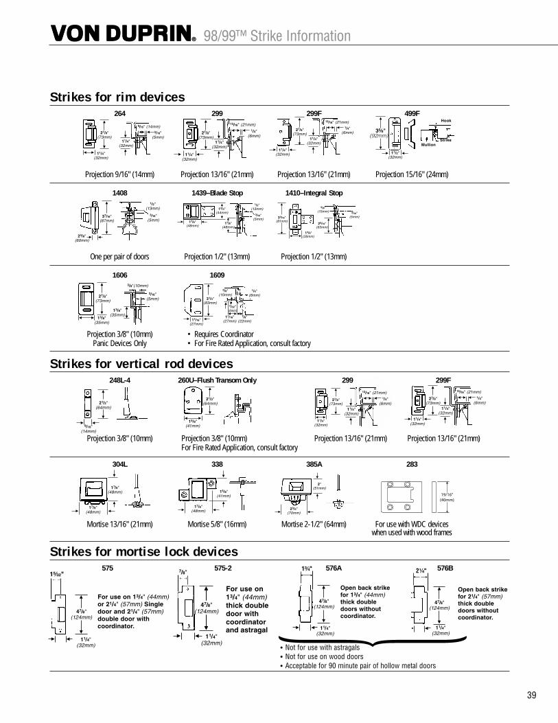
39
98/99™ Strike Information
Strikes for rim devices264 299 299F 499F
Projection 9/16" (14mm) Projection 13/16" (21mm) Projection 13/16" (21mm) Projection 15/16" (24mm)
1408 1439–Blade Stop 1410–Integral Stop
One per pair of doors Projection 1/2" (13mm) Projection 1/2" (13mm)
1606 1609
Projection 3/8" (10mm) • Requires CoordinatorPanic Devices Only • For Fire Rated Application, consult factory
Strikes for vertical rod devices248L-4 260U–Flush Transom Only 299 299F
Projection 3/8" (10mm) Projection 3/8" (10mm) Projection 13/16" (21mm) Projection 13/16" (21mm)For Fire Rated Application, consult factory
304L 338 385A 283
Mortise 13/16" (21mm) Mortise 5/8" (16mm) Mortise 2-1/2" (64mm) For use with WDC deviceswhen used with wood frames
Strikes for mortise lock devices575 575-2 576A 576B
• Not for use with astragals• Not for use on wood doors• Acceptable for 90 minute pair of hollow metal doors

98-F/99-F Fire Exit Rim Device Standard Trim
7
Exit only Dummy Trim Night Latch Night LatchPull when Dogged Key Retracts Latchbolt Key Retracts Latchbolt
(Not recommened for Fire Device) Optional Pull Required
Product Description
Trim Description
Escutcheon Plate Size
Pull Center to Center
Projection
ANSI Function
Cylinder Type
Optional Trim(See pages 32 – 34)
#425 SNB optional-HMDReq. WD w/o SLM Pkg. #825 SNB Req. WD w/o SLM Pkg.#425 SNB Req. w/ 499F
98EO-F –– 98NL-F 98NL-OP-F99EO-F –– 99NL-F 99NL-OP-F
110NL-MD110NL-WD
3" x 14³�₁₆" x ³�₃₂" 3" x 14³�₁₆" x ³�₃₂"(76x360x2mm) (76x360x2mm)
–– 5¹�₂" (140mm) 5¹�₂" (140mm) ––
–– 2" (51mm) 2" (51mm) ––
01 02 03 03
–– –– Rim Rim
x990EO x991K-DT x991K-NLx992EO x992L-DT x992L-NLx994EO x994L-DT x994L-NLx996EO x996L-DT x996L-NL
x696DT x696NLx697DT x697NL
6 2 2 6
2 2 2 2
2 2 2 2
–– 990DT 990NL-R/V
–– ––
Lever Lever – Night Latch Lever – Blank Escutcheon Lever Dummy TrimKey Locks & Unlocks Key Retracts Latchbolt Always operable Pull when Dogged
(No Cylinder) (Not recommened for Fire Device)
Product Description
Trim Description
Escutcheon Plate Size
Pull Center to Center
Projection
ANSI Function
Cylinder Type
Optional Trim(See pages 32 – 34)#425 SNB optional-HMDReq. WD w/o SLM Pkg. #825 SNB Req. WD w/o SLM Pkg.#425 SNB Req. w/ 499F
98L-F 98L-NL-F 98L-BE-F ––99L-F 99L-NL-F 99L-BE-F ––
996L-R/V 996L-NL-R/V 996L-BE-R/V 996L-DT-R/V
2³�₄" x 10³�₄" x ²⁷�₃₂" 2³�₄" x 10³�₄" x ²⁷�₃₂" 2³�₄" x 10³�₄" x ²⁷�₃₂" 2³�₄" x 10³�₄" x ²⁷�₃₂"(70x273x21mm) (70x273x21mm) (70x273x21mm) (70x273x21mm)
–– –– –– ––
2⁷�₈" (73mm) 2⁷�₈" (73mm) 2⁷�₈" (73mm) 2⁷�₈" (73mm)
08 09 –– 02
Rim Rim –– ––
x992L x992L-NL x992L-BE x992L-DTx994L x994L-NL x994L-BE x994L-DT
2 2 2 2
2 2 2 2
2 2 2 2
For optional trims and functions see pages 32-34

Signal Switch RX and LX
17
RX (request to exit) signal switch featureis used to signal the use of an openingfrom the push side. When the push padis depressed, the switch is activated.These devices are equipped with aninternal SPDT (single pole double throw)switch that monitors the touch bar.See Low Current option for computeroperated system applications.
RX2 (double request to exit) features 2 RX switches.
LX (latchbolt monitoring) signal switchmonitors both egress and access of anopening. When the latchbolt is retracted,the switch is activated. These devices areequipped with an internal SPDT (singlepole double throw) switch that monitorsthe latchbolt position. See Low Currentoption for computer operated systemapplications.
LC (low current) option is available forRX and LX switches. (Most commonlyused in computer operated monitoringsystems.) The RX2 is not available in lowcurrent.
Signal Switches are available on 22, 33A,35A, 55, 88, 98, 99 series devices. Thelow current version is not available withthe 55 and 88 series devices.
The INPACT 94/95 series devices areonly available with the LX switch option.
The device can be connected to a securityconsole, or may be used as a single dooralarm, when used with a horn and powersupply. A continuous current electrictransfer must be used for transferringthe signal from the frame to the door.
Signal Switches can be used in combinationwith other electrical functions (EL, E).
• RX or RX2 may be combined with the E(electric unlocking) mortise lock device.
• For latchbolt monitoring on a mortiselock device, specify a SS7500 lock.
• LX and RX switches can be combined.Example: LX-RX99L.
• LX, RX or RX2 switches can be used incombination with EL (electric latchretraction) option.
RX, RX2 and LX switches are availablefor factory or field installation.
RX and LX switches should not be usedto control a load, but as a signalingswitch.
Rim device shown — Refer to 33A/35A or 98/99 series catalog for complete product information, mounting styles, outside trim, finishes, etc.
SPECIFICATIONSRX or LX:Switch rated 0.5 amperes @ 24VAC/DC resistiveLow Current RX or LXSwitch rated 0.05 amperes @ 24VAC/DC resistive
UL listed FVSR SA163 panic hardwareand/or GXHX R4504(N) fire exit hardware— consult device catalog for completedevice listing information.
LX98/LX99RX98/RX99
LX33A/LX35ARX33A/RX35A
To Order, Specify:For Factory Installed:
Prefix: RX Request to ExitRX2 Double Request to ExitLX Latchbolt MonitoringLXRX Latchbolt Monitoring/Request to Exit Combination
RXLC Low Current Request to ExitLXLC Low Current Latchbolt MonitoringLXRXLC Low Current Latchbolt Monitoring/Request to Exit Combination
Example: RX99L
For Field Installed:
1. Specify switch option (RX, LX, RX-LC, LX-LC).2. Specify “field”.3. For LX, specify device size 3´ or 4´.4. For LX, specify if used with EL (electric latch retraction) option.5. To convert an existing RX option to RX2, specify RX-AUX.
Example: LX 3´ Field
RX Wiring LX Wiring
RX-LC Wiring LX-LC Wiring

98-F/99-F Rim Fire Exit Device
6 © 2004 Ingersoll-Rand. May be copied for use with specification submittal.
98-F and 99-F rim fire exit devices for all types of single doors up to 4´ x 10´ (1219mm x 3048mm) or8´ x 10´ (2438mm x 3048mm) double doors with 9954 or 9854 mullion, UL listed for Fire Exit Hardware. Seepage 41 for detailed information on UL listed fire exit hardware label and door opening size information.Devices are ANSI A156.3 – 2001 Grade 1. The 98-F device has a smooth mechanism case and the 99-F devicehas a grooved case. The rim device is non-handed except when the following device options are used: -2 (DoubleCylinder) or SS (Signal Switch). See Opposite page for available outside trim and device functions.
The 98-F/99-F devices are available in the following finishes: US3, US4, US10, US26, US26D, US28, 313AN,315AN and US32D for the 98-F device only. See page 52 for component finishes and the inside cover forfinish chips.
299F Strike
499F StrikeWith 9854/9954
Mullion
Specifications
Device Functions Device ships EO/DT/NL. Field selectable. For TP,K,or L remove NL drive screw from device
Device Lengths 3’ 2’4" to 3’ (711mm to 914 mm) Door Size4’ 2’10" to 4’ (864 mm to 1219 mm) Door Size
Strikes 299F – Dull Black, 499F with MullionsOptional Strikes – see page 39
Dogging Feature No Mechanical Dogging, EL option available
Electric Options LX Latchbolt Monitor Switch see page 42 RX Pushpad Monitor Switch see page 42 RX2 Double Pushpad Monitor Switch see page 42E Electric Locking & Unlocking see page 44EL Electric Latch Retraction see page 43 SS Signal Switch see page 43 CX Chexit Delayed Exit see page 45ALK Alarm Exit Kit see page 42
Miscellaneous Options PN Pneumatic Latch Retraction see page 48 -2 Double Cylinder see page 48 GBK Glass Bead Kit see page 49
Fasteners & Includes 1 ³�₄" (19mm) – 2 ¹�₄" (57mm) Wood & Metal DoorsSex Bolts (SNB) Optional SNB available for device, see next page for quantities
Optional SLM Blocking Pkg for wood doors with SLM blockingSNB required for wood doors, unless SLM Blocking Pkg specified
Latch Bolt Deadlocking, ³�₄" (19mm) throw
Device Centerline from 39 ¹³�₁₆" (1011 mm)Finished Floor 39 ¹¹�₁₆" (1008 mm) with Mullion
Center Case Dimensions 8" x 2 ³�₄" x 2 ³�₈" (203mm x 70mm x 60mm)
Mechanism Case Dimensions 2 ¹�₄" x 2 ¹�₄" (57mm x 57mm)
Projection Pushbar Neutral – 3 ¹³�₁₆" (97 mm)Pushbar Depressed – 3 ¹�₁₆" (78 mm)
See page 53 for How to Order specification

39
98/99™ Strike Information
Strikes for rim devices264 299 299F 499F
Projection 9/16" (14mm) Projection 13/16" (21mm) Projection 13/16" (21mm) Projection 15/16" (24mm)
1408 1439–Blade Stop 1410–Integral Stop
One per pair of doors Projection 1/2" (13mm) Projection 1/2" (13mm)
1606 1609
Projection 3/8" (10mm) • Requires CoordinatorPanic Devices Only • For Fire Rated Application, consult factory
Strikes for vertical rod devices248L-4 260U–Flush Transom Only 299 299F
Projection 3/8" (10mm) Projection 3/8" (10mm) Projection 13/16" (21mm) Projection 13/16" (21mm)For Fire Rated Application, consult factory
304L 338 385A 283
Mortise 13/16" (21mm) Mortise 5/8" (16mm) Mortise 2-1/2" (64mm) For use with WDC deviceswhen used with wood frames
Strikes for mortise lock devices575 575-2 576A 576B
• Not for use with astragals• Not for use on wood doors• Acceptable for 90 minute pair of hollow metal doors
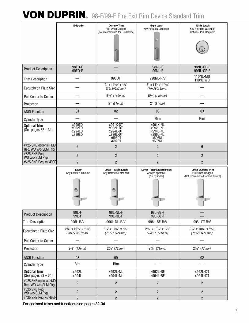
98-F/99-F Fire Exit Rim Device Standard Trim
7
Exit only Dummy Trim Night Latch Night LatchPull when Dogged Key Retracts Latchbolt Key Retracts Latchbolt
(Not recommened for Fire Device) Optional Pull Required
Product Description
Trim Description
Escutcheon Plate Size
Pull Center to Center
Projection
ANSI Function
Cylinder Type
Optional Trim(See pages 32 – 34)
#425 SNB optional-HMDReq. WD w/o SLM Pkg. #825 SNB Req. WD w/o SLM Pkg.#425 SNB Req. w/ 499F
98EO-F –– 98NL-F 98NL-OP-F99EO-F –– 99NL-F 99NL-OP-F
110NL-MD110NL-WD
3" x 14³�₁₆" x ³�₃₂" 3" x 14³�₁₆" x ³�₃₂"(76x360x2mm) (76x360x2mm)
–– 5¹�₂" (140mm) 5¹�₂" (140mm) ––
–– 2" (51mm) 2" (51mm) ––
01 02 03 03
–– –– Rim Rim
x990EO x991K-DT x991K-NLx992EO x992L-DT x992L-NLx994EO x994L-DT x994L-NLx996EO x996L-DT x996L-NL
x696DT x696NLx697DT x697NL
6 2 2 6
2 2 2 2
2 2 2 2
–– 990DT 990NL-R/V
–– ––
Lever Lever – Night Latch Lever – Blank Escutcheon Lever Dummy TrimKey Locks & Unlocks Key Retracts Latchbolt Always operable Pull when Dogged
(No Cylinder) (Not recommened for Fire Device)
Product Description
Trim Description
Escutcheon Plate Size
Pull Center to Center
Projection
ANSI Function
Cylinder Type
Optional Trim(See pages 32 – 34)#425 SNB optional-HMDReq. WD w/o SLM Pkg. #825 SNB Req. WD w/o SLM Pkg.#425 SNB Req. w/ 499F
98L-F 98L-NL-F 98L-BE-F ––99L-F 99L-NL-F 99L-BE-F ––
996L-R/V 996L-NL-R/V 996L-BE-R/V 996L-DT-R/V
2³�₄" x 10³�₄" x ²⁷�₃₂" 2³�₄" x 10³�₄" x ²⁷�₃₂" 2³�₄" x 10³�₄" x ²⁷�₃₂" 2³�₄" x 10³�₄" x ²⁷�₃₂"(70x273x21mm) (70x273x21mm) (70x273x21mm) (70x273x21mm)
–– –– –– ––
2⁷�₈" (73mm) 2⁷�₈" (73mm) 2⁷�₈" (73mm) 2⁷�₈" (73mm)
08 09 –– 02
Rim Rim –– ––
x992L x992L-NL x992L-BE x992L-DTx994L x994L-NL x994L-BE x994L-DT
2 2 2 2
2 2 2 2
2 2 2 2
For optional trims and functions see pages 32-34

Signal Switch RX and LX
17
RX (request to exit) signal switch featureis used to signal the use of an openingfrom the push side. When the push padis depressed, the switch is activated.These devices are equipped with aninternal SPDT (single pole double throw)switch that monitors the touch bar.See Low Current option for computeroperated system applications.
RX2 (double request to exit) features 2 RX switches.
LX (latchbolt monitoring) signal switchmonitors both egress and access of anopening. When the latchbolt is retracted,the switch is activated. These devices areequipped with an internal SPDT (singlepole double throw) switch that monitorsthe latchbolt position. See Low Currentoption for computer operated systemapplications.
LC (low current) option is available forRX and LX switches. (Most commonlyused in computer operated monitoringsystems.) The RX2 is not available in lowcurrent.
Signal Switches are available on 22, 33A,35A, 55, 88, 98, 99 series devices. Thelow current version is not available withthe 55 and 88 series devices.
The INPACT 94/95 series devices areonly available with the LX switch option.
The device can be connected to a securityconsole, or may be used as a single dooralarm, when used with a horn and powersupply. A continuous current electrictransfer must be used for transferringthe signal from the frame to the door.
Signal Switches can be used in combinationwith other electrical functions (EL, E).
• RX or RX2 may be combined with the E(electric unlocking) mortise lock device.
• For latchbolt monitoring on a mortiselock device, specify a SS7500 lock.
• LX and RX switches can be combined.Example: LX-RX99L.
• LX, RX or RX2 switches can be used incombination with EL (electric latchretraction) option.
RX, RX2 and LX switches are availablefor factory or field installation.
RX and LX switches should not be usedto control a load, but as a signalingswitch.
Rim device shown — Refer to 33A/35A or 98/99 series catalog for complete product information, mounting styles, outside trim, finishes, etc.
SPECIFICATIONSRX or LX:Switch rated 0.5 amperes @ 24VAC/DC resistiveLow Current RX or LXSwitch rated 0.05 amperes @ 24VAC/DC resistive
UL listed FVSR SA163 panic hardwareand/or GXHX R4504(N) fire exit hardware— consult device catalog for completedevice listing information.
LX98/LX99RX98/RX99
LX33A/LX35ARX33A/RX35A
To Order, Specify:For Factory Installed:
Prefix: RX Request to ExitRX2 Double Request to ExitLX Latchbolt MonitoringLXRX Latchbolt Monitoring/Request to Exit Combination
RXLC Low Current Request to ExitLXLC Low Current Latchbolt MonitoringLXRXLC Low Current Latchbolt Monitoring/Request to Exit Combination
Example: RX99L
For Field Installed:
1. Specify switch option (RX, LX, RX-LC, LX-LC).2. Specify “field”.3. For LX, specify device size 3´ or 4´.4. For LX, specify if used with EL (electric latch retraction) option.5. To convert an existing RX option to RX2, specify RX-AUX.
Example: LX 3´ Field
RX Wiring LX Wiring
RX-LC Wiring LX-LC Wiring

Auxiliary Hardware and General Information
6 © 2005 Ingersoll-Rand. May be copied for use with specification submittal.
Sex BoltsSex Bolts when ordered with devices may be furnished with screw lengths different than shown in Column B. Onpage 7, Column B indicates popular sizes. Sex Bolts ordered separately are not furnished with screws. If screws arerequired refer to chart on page 7 and order screws by description as a separate item. Other screw lengths may beused based on minimum and maximum allowable thread engagement, shown in column “C.” Quantity required ––refer to device section, quantities differ depending on outside trim.
425 sex bolts are required for 22/88/98/99 series fire rated devices when used on wood door applications. Whenwood doors are specified for these devices, sex bolts will be added to the device application unless SLM blockingpackage is specified.
825 sex bolts are required with 98-F/99-F rim devices on wood door applications using EO, NL, TP, K and L outsidetrims. Two 825 sex bolts will be added to the device application unless SLM blocking package is specified.
To Order, Specify:1. Model number2. Quantity (2 per package)3. Finish4. Door thickness other than 1³|₄´´ (44mm).
Refer to page 7 for A, B and C lengths
AC
B
AC
B
325,425,625A & 625B
525
325
425
825
625A
625B

Center Case
Device Door Sex Bolt Sex Bolt Sex BoltType Thickness B B B
No. A No. A No. A
C C CThread Thread ThreadEngagement Engagement EngagementMin. – Max. Min. – Max. Min. – Max.
1 ´́ (44mm) 425 1 ´́ 10-24 x 1´́ PPHMS ´́ – ´́ 425 1 ´́ 10-24 x ´́ PPHMS ´́ – ´́ 325
2 ´́ (57mm) 425 1 ´́ 10-24 x 1 ´́ PPHMS ´́ – ´́ 425 1 ´́ 10-24 x 1 ´́ PPHMS ´́ – ´́ 325
1 ´́ (44mm) 325 1 ´́ -20 x 1´́ FPHMS ´́ – ´́ 425 1 ´́ 10-24 x ´́ PPHMS ´́ – ´́
2 ´́ (57mm) 325 1 ´́ -20 x 1 ´́ FPHMS ´́ – ´́ 425 1 ´́ 10-24 x 1 ´́ PPHMS ´́ – ´́
1 ´́ (44mm) 425 1 ´́ 10-24 x 1 ´́ OPHMS ´́ – ´́ 425 1 ´́ 10-24 x 1 ´́ OPHMS ´́ – ´́ 425 1 ´́ 10-24 x ´́ PPHMS ´́ – ´́
2 ´́ (57mm) 425 1 ´́ 10-24 x 2´́ OPHMS ´́ – ´́ 425 1 ´́ 10-24 x 2´́ OPHMS ´́ – ´́ 425 1 ´́ 10-24 x 1 ´́ PPHMS ´́ – ´́
1 ´́ (44mm) 425 1 ´́ 10-24 x 1´́ PPHMS ´́ – ´́ 425 1 ´́ 10-24 x ´́ PPHMS ´́ –
2227,2227-F
3327A3527A
8827,8827-F
9827,9827-F98579857-F
9927,9927-F99579957-F
Screw Screw Screw
325325325325
(FPHMS –– Flat Phillips Head Machine Screw; OPHMS –– Oval Phillips Head Machine Screw; PPHMS –– Pan Phillips Head Machine ScrewUFPHMS –– Undercut Flat Phillips Head Machine Screw)
Hinge Case Top & Bottom Latch Case
₄ -20 x ´́ UFPHMS1 ´́
₄ -20 x ́ ́UFPHMS1 ´́ 1
´́ 325 ₄ -20 x ´́ UFPHMS1 ´́ ´́ – ´́
2 ´́ (57mm) 425 1 ´́ 10-24 x 1 ´́ PPHMS ´́ – ´́ 425 1 ´́ 10-24 x 1 ´́ PPHMS ´́ – ´́ 325 ₄ -20 x ´́ UFPHMS1 ´́ ´́ – ´́1
1 ´́
1 ´́
₄ -20 x ´́ UFPHMS ´́ –
₄ -20 x ´́ UFPHMS ´́ – ´́
´́ – ´́
´́ – ´́
1 ´́
Auxiliary Hardware and General Information
7
Rim, Mortise and Concealed Vertical Rod
Surface Vertical Rod
Center Case Hinge Case
Device Door Sex Bolt Sex BoltType Thickness B B
No. A No. A
C CThread ThreadEngagement EngagementMin. – Max. Min. – Max.
1 ´́ (44mm) 425 1 ´́ 10-24 x 1´́ PPHMS ´́ – ´́ 425 1 ´́ 10-24 x ´́ PPHMS ´́ – ´́
2 ´́ (57mm) 425 1 ´́ 10-24 x 1 ´́ PPHMS ´́ – ´́ 425 1 ´́ 10-24 x 1 ´́ PPHMS ´́ – ´́
1 ´́ (44mm) 325 1 ´́ -20 x 1´́ FPHMS ´́ – ´́ 425 1 ´́ 10-24 x ´́ PPHMS ´́ – ´́
2 ´́ (57mm) 325 1 ´́ -20 x 1 ´́ FPHMS ´́ – ´́ 425 1 ´́ 10-24 x 1 ´́ PPHMS ´́ – ´́
1 ´́ (44mm) 625A 2 ´́ 12-24 x ´́ OPHMS ´́ – ´́ 625A 2 ´́ 12-24 x ´́ OPHMS ´́ – ´́
2 ´́ (57mm) 625B 2 ́ ´ 12-24 x ´́ OPHMS ´́ – 1´́ 625B 2 ´́ 12-24 x 1 ´́ OPHMS ´́ – 1´́
1 ´́ (44mm) –– –– –– –– 625A 2 ´́ 12-24 x ´́ OPHMS ´́ – ´́
2 ´́ (57mm) –– –– –– –– 625B 2 ´́ 12-24 x 1 ´́ OPHMS ´́ – 1´́
1 ´́ (44mm) 425 1 ´́ 10-24 x 1 ´́ OPHMS ´́ – ´́ 425 1 ´́ 10-24 x 1 ´́ OPHMS ´́ – ´́
2 ´́ (57mm) 425 1 ´́ 10-24 x 2´́ OPHMS ´́ – ´́ 425 1 ´́ 10-24 x 2´́ OPHMS ´́ – ´́
1 ´́ (44mm) –– –– –– –– 425 1 ´́ 10-24 x 1 ´́ OPHMS ´́ – ´́
2 ´́ (57mm) –– –– –– –– 425 1 ´́ 10-24 x 2´́ OPHMS ´́ – ´́
1 ´́ (44mm) 425 1 ´́ 10-24 x 1´́ PPHMS ´́ – ´́ 425 1 ´́ 10-24 x 1´́ PPHMS ´́ – ´́
2 ´́ (57mm) 425 1 ´́ 10-24 x 1 ´́ PPHMS ´́ – ´́ 425 1 ´́ 10-24 x 1 ´́ PPHMS ´́ – ´́
1 ´́ (44mm) 425 1 ´́ 10-24 x ´́ PPHMS ´́ – ´́
2 ´́ (57mm) 425 1 ´́ 10-24 x 1 ´́ PPHMS ´́ – ´́
22
33A, 3347A, 3347A-F35A, 3547A, 3547A-F
55
5575, 5575-F5547, 5547-F
88, 88-F, 8875,8875-F
8847-F
98, 9875, 9875-F,9847, 9847-F,99, 9975, 9975-F,9947, 9947-F
98-F, 99-F*
425 1 ´́ 10-24 x 1´́ PPHMS ´́ – ´́ 825A* 1 ´́ 10-24 x ´́ PPHMS ´́ – ´́ 425 1 ´́ 10-24 x 1 ´́ PPHMS ´́ – ´́
825B* 2 ´́ 10-24 x ´́ PPHMS ´́ – ´́
Screw Screw
* For use with outside trims, see page 6 for details
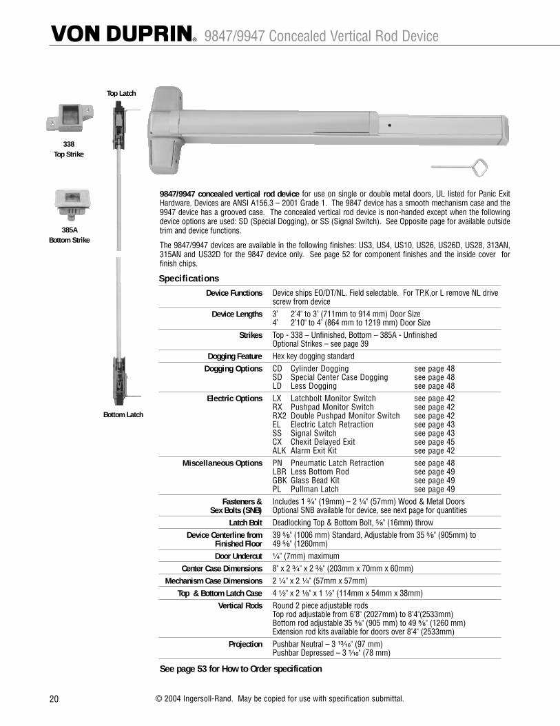
9847/9947 Concealed Vertical Rod Device
20 © 2004 Ingersoll-Rand. May be copied for use with specification submittal.
9847/9947 concealed vertical rod device for use on single or double metal doors, UL listed for Panic ExitHardware. Devices are ANSI A156.3 – 2001 Grade 1. The 9847 device has a smooth mechanism case and the9947 device has a grooved case. The concealed vertical rod device is non-handed except when the followingdevice options are used: SD (Special Dogging), or SS (Signal Switch). See Opposite page for available outsidetrim and device functions.
The 9847/9947 devices are available in the following finishes: US3, US4, US10, US26, US26D, US28, 313AN,315AN and US32D for the 9847 device only. See page 52 for component finishes and the inside cover forfinish chips.
See page 53 for How to Order specification
Top Latch
Bottom Latch
385A Bottom Strike
338 Top Strike
SpecificationsDevice Functions Device ships EO/DT/NL. Field selectable. For TP,K,or L remove NL drive
screw from deviceDevice Lengths 3’ 2’4" to 3’ (711mm to 914 mm) Door Size
4’ 2’10" to 4’ (864 mm to 1219 mm) Door SizeStrikes Top - 338 – Unfinished, Bottom – 385A - Unfinished
Optional Strikes – see page 39Dogging Feature Hex key dogging standard
Dogging Options CD Cylinder Dogging see page 48 SD Special Center Case Dogging see page 48 LD Less Dogging see page 48
Electric Options LX Latchbolt Monitor Switch see page 42 RX Pushpad Monitor Switch see page 42 RX2 Double Pushpad Monitor Switch see page 42EL Electric Latch Retraction see page 43 SS Signal Switch see page 43 CX Chexit Delayed Exit see page 45ALK Alarm Exit Kit see page 42
Miscellaneous Options PN Pneumatic Latch Retraction see page 48 LBR Less Bottom Rod see page 49 GBK Glass Bead Kit see page 49PL Pullman Latch see page 49
Fasteners & Includes 1 ³�₄" (19mm) – 2 ¹�₄" (57mm) Wood & Metal DoorsSex Bolts (SNB) Optional SNB available for device, see next page for quantities
Latch Bolt Deadlocking Top & Bottom Bolt, ⁵�₈" (16mm) throw Device Centerline from 39 ⁵�₈" (1006 mm) Standard, Adjustable from 35 ⁵�₈" (905mm) to
Finished Floor 49 ⁵�₈" (1260mm)Door Undercut ¹�₄" (7mm) maximum
Center Case Dimensions 8" x 2 ³�₄" x 2 ³�₈" (203mm x 70mm x 60mm)Mechanism Case Dimensions 2 ¹�₄" x 2 ¹�₄" (57mm x 57mm)
Top & Bottom Latch Case 4 ¹�₂" x 2 ¹�₈" x 1 ¹�₂" (114mm x 54mm x 38mm)Vertical Rods Round 2 piece adjustable rods
Top rod adjustable from 6’8" (2027mm) to 8’4"(2533mm)Bottom rod adjustable 35 ⁵�₈" (905 mm) to 49 ⁵�₈" (1260 mm)Extension rod kits available for doors over 8’4" (2533mm)
Projection Pushbar Neutral – 3 ¹³�₁₆" (97 mm)Pushbar Depressed – 3 ¹�₁₆" (78 mm)

39
98/99™ Strike Information
Strikes for rim devices264 299 299F 499F
Projection 9/16" (14mm) Projection 13/16" (21mm) Projection 13/16" (21mm) Projection 15/16" (24mm)
1408 1439–Blade Stop 1410–Integral Stop
One per pair of doors Projection 1/2" (13mm) Projection 1/2" (13mm)
1606 1609
Projection 3/8" (10mm) • Requires CoordinatorPanic Devices Only • For Fire Rated Application, consult factory
Strikes for vertical rod devices248L-4 260U–Flush Transom Only 299 299F
Projection 3/8" (10mm) Projection 3/8" (10mm) Projection 13/16" (21mm) Projection 13/16" (21mm)For Fire Rated Application, consult factory
304L 338 385A 283
Mortise 13/16" (21mm) Mortise 5/8" (16mm) Mortise 2-1/2" (64mm) For use with WDC deviceswhen used with wood frames
Strikes for mortise lock devices575 575-2 576A 576B
• Not for use with astragals• Not for use on wood doors• Acceptable for 90 minute pair of hollow metal doors
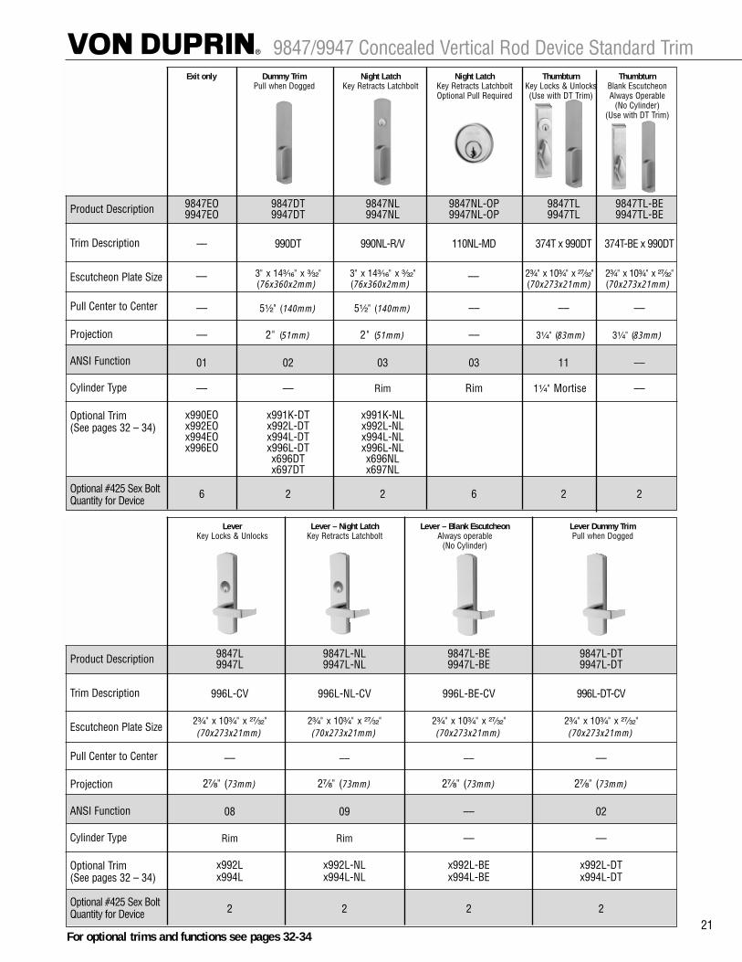
9847/9947 Concealed Vertical Rod Device Standard Trim
21
Exit only Dummy Trim Night Latch Night Latch Thumbturn ThumbturnPull when Dogged Key Retracts Latchbolt Key Retracts Latchbolt Key Locks & Unlocks Blank Escutcheon
Optional Pull Required (Use with DT Trim) Always Operable(No Cylinder)
(Use with DT Trim)
Product Description
Trim Description
Escutcheon Plate Size
Pull Center to Center
Projection
ANSI Function
Cylinder Type
Optional Trim(See pages 32 – 34)
Optional #425 Sex Bolt Quantity for Device
9847EO 9847DT 9847NL 9847NL-OP 9847TL 9847TL-BE9947EO 9947DT 9947NL 9947NL-OP 9947TL 9947TL-BE
–– 990DT 990NL-R/V 110NL-MD 374T x 990DT 374T-BE x 990DT
3" x 14³�₁₆" x ³�₃₂" 3" x 14³�₁₆" x ³�₃₂" 2³�₄" x 10³�₄" x ²⁷�₃₂" 2³�₄" x 10³�₄" x ²⁷�₃₂"(76x360x2mm) (76x360x2mm) (70x273x21mm) (70x273x21mm)
–– 5¹�₂" (140mm) 5¹�₂" (140mm) –– –– ––
–– 2" (51mm) 2" (51mm) –– 3¹�₄" (83mm) 3¹�₄" (83mm)
01 02 03 03 11 ––
–– –– Rim Rim 1¹�₄" Mortise ––
x990EO x991K-DT x991K-NLx992EO x992L-DT x992L-NLx994EO x994L-DT x994L-NLx996EO x996L-DT x996L-NL
x696DT x696NLx697DT x697NL
6 2 2 6 2 2
–– ––
Lever Lever – Night Latch Lever – Blank Escutcheon Lever Dummy TrimKey Locks & Unlocks Key Retracts Latchbolt Always operable Pull when Dogged
(No Cylinder)
Product Description
Trim Description
Escutcheon Plate Size
Pull Center to Center
Projection
ANSI Function
Cylinder Type
Optional Trim(See pages 32 – 34)
Optional #425 Sex Bolt Quantity for Device
9847L 9847L-NL 9847L-BE 9847L-DT9947L 9947L-NL 9947L-BE 9947L-DT
996L-CV 996L-NL-CV 996L-BE-CV 996L-DT-CV
2³�₄" x 10³�₄" x ²⁷�₃₂" 2³�₄" x 10³�₄" x ²⁷�₃₂" 2³�₄" x 10³�₄" x ²⁷�₃₂" 2³�₄" x 10³�₄" x ²⁷�₃₂"(70x273x21mm) (70x273x21mm) (70x273x21mm) (70x273x21mm)
–– –– –– ––
2⁷�₈" (73mm) 2⁷�₈" (73mm) 2⁷�₈" (73mm) 2⁷�₈" (73mm)
08 09 –– 02
Rim Rim –– ––
x992L x992L-NL x992L-BE x992L-DTx994L x994L-NL x994L-BE x994L-DT
2 2 2 2
For optional trims and functions see pages 32-34

Signal Switch RX and LX
17
RX (request to exit) signal switch featureis used to signal the use of an openingfrom the push side. When the push padis depressed, the switch is activated.These devices are equipped with aninternal SPDT (single pole double throw)switch that monitors the touch bar.See Low Current option for computeroperated system applications.
RX2 (double request to exit) features 2 RX switches.
LX (latchbolt monitoring) signal switchmonitors both egress and access of anopening. When the latchbolt is retracted,the switch is activated. These devices areequipped with an internal SPDT (singlepole double throw) switch that monitorsthe latchbolt position. See Low Currentoption for computer operated systemapplications.
LC (low current) option is available forRX and LX switches. (Most commonlyused in computer operated monitoringsystems.) The RX2 is not available in lowcurrent.
Signal Switches are available on 22, 33A,35A, 55, 88, 98, 99 series devices. Thelow current version is not available withthe 55 and 88 series devices.
The INPACT 94/95 series devices areonly available with the LX switch option.
The device can be connected to a securityconsole, or may be used as a single dooralarm, when used with a horn and powersupply. A continuous current electrictransfer must be used for transferringthe signal from the frame to the door.
Signal Switches can be used in combinationwith other electrical functions (EL, E).
• RX or RX2 may be combined with the E(electric unlocking) mortise lock device.
• For latchbolt monitoring on a mortiselock device, specify a SS7500 lock.
• LX and RX switches can be combined.Example: LX-RX99L.
• LX, RX or RX2 switches can be used incombination with EL (electric latchretraction) option.
RX, RX2 and LX switches are availablefor factory or field installation.
RX and LX switches should not be usedto control a load, but as a signalingswitch.
Rim device shown — Refer to 33A/35A or 98/99 series catalog for complete product information, mounting styles, outside trim, finishes, etc.
SPECIFICATIONSRX or LX:Switch rated 0.5 amperes @ 24VAC/DC resistiveLow Current RX or LXSwitch rated 0.05 amperes @ 24VAC/DC resistive
UL listed FVSR SA163 panic hardwareand/or GXHX R4504(N) fire exit hardware— consult device catalog for completedevice listing information.
LX98/LX99RX98/RX99
LX33A/LX35ARX33A/RX35A
To Order, Specify:For Factory Installed:
Prefix: RX Request to ExitRX2 Double Request to ExitLX Latchbolt MonitoringLXRX Latchbolt Monitoring/Request to Exit Combination
RXLC Low Current Request to ExitLXLC Low Current Latchbolt MonitoringLXRXLC Low Current Latchbolt Monitoring/Request to Exit Combination
Example: RX99L
For Field Installed:
1. Specify switch option (RX, LX, RX-LC, LX-LC).2. Specify “field”.3. For LX, specify device size 3´ or 4´.4. For LX, specify if used with EL (electric latch retraction) option.5. To convert an existing RX option to RX2, specify RX-AUX.
Example: LX 3´ Field
RX Wiring LX Wiring
RX-LC Wiring LX-LC Wiring

.135" (3.4) Neoprene
5.00" (127.0)
.500"(12.7) .250"
(6.4)
Rabbeted Saddles
.500"(12.7)
.187" (4.7)Neoprene
1.750" (44.5)
.875"(22.2)
4.860" (123.4)
.500"(12.7)
.135" (3.4)Neoprene
1.750"(44.5)
.875"(22.2)
3.562" (90.5)
.500"(12.7) .125" (3.2)
3.687" (93.6)
.125" (3.2)
Neoprene
1.750"(44.5)
.500"(12.7)
.125" (3.2)
Neoprene
5.00" (127.0)
1.750" (44.5)
.125"(3.2)
.130"(3.3)Neoprene
5.00"(127.0)
1.500"(38.1)
.500"(12.7)
.875"(22.2)
.500"(12.7)
.140"(3.6)Neoprene
4.50"(114.3)
1.00"(25.4)
2.750"(69.9)
.125" (3.2)
.250"(6.4)
Neoprene
1.750" (44.5)
.625"(15.8)
5.00" (127.0)
For Latch Track Hardware
#565A #565B
#563A
#564A #564B
#566A #566B
#560A
#65A
#561A
#265A
#267A
For Latch Track Hardware
#563, 564, 565, 566 TYPE
#65, 265, 560 TYPE For Latch Track Hardware (Option)
.250"(6.4)
Neoprene
1.750" (44.5)
2.125" (54.0)
.625"(15.8)
Tile TileSadd
les
For Latch Track Hardware
SPECIFY THIS SPECIAL FEATURE
The neoprene gasket isdesigned with an extra lip for double seal protection,and to compensate for anywarping or misalignmentduring installation.
Compress-O-Matic®
14
Note: A = AluminumB = Bronze
.500"(12.7)
.145" (3.7)
Neoprene
6.00" (152.4)
1.900" (48.3)
.125"(3.2)
#568A

Sill ProtectionAutomatic Door Bottoms
Heavy Duty
#360AMortised
#364AMortised
#369AMortised
1.00"25.4)
.916"(23.3)
1.90"(48.3)
.083"(2.2)
#8 x 1.250" (31.8) SMS
1.00" (25.4)
.916" (23.3)
1.90" (48.3)
.083" (2.2)
#8 x 1.25" (31.8) SMS
1.590"(40.4)
.125"(3.2)
.375"(9.5)
.916" (23.3)
1.00"(25.4)
Extruded AluminumMill Finish
#6 x .500"(12.7) SMS
1.590"(40.4)
.375"
.916" (23.3)
1.00" (25.4)
Extruded AluminumMill Finish
#6 x .500" (12.7) SMS
.125"(3.2)
(9.5)
#361AA#361D#361G
#362AA#362D#362G
Surface-Mounted Semi-Mortised
#365AA#365D#365G
#366AA#366D#366G
Surface-Mounted Semi-Mortised
1.58" (40.1)
.375" (9.5)
.916" (23.3)
Extruded AluminumMill Finish
#6 x .500" (12.7) SMS
SteelPlate
Rubber extends .500" (12.7)
Max. Effective Drop .562" (14.3)
.125" (3.2)
Mortised
#340,350,360,364
Surface-
Mounted
#351,361,365Semi-Mortised
#352,362,366
Note: A = Aluminum AA = Anodized AluminumD = Dr. Bronze Anodized Bk = Black AnodizedG = Simulated Bronze Anodized
24
Doo
r Bot
tom
s
Max. Effective Drop .562"(14.3)
.916"(23.3)
1.900"(48.3)
.093"(2.4)
Magnet
#8 x 1.250"(31.8) SMS
DoubleNeopreneSeal
SteelPlate
.500"(12.7)
Can also be used with #950 Cam Lift Hinges
#367AA#367D#367G
#368AA#368D#368G
Surface-Mounted Semi-Mortised

.250"(6.4)
.150" — .375" (3.8) (9.5)
.187" (4.7)
.250"(6.4)
.437"(11.1)
.437"(11.1)
.125"(3.2)
.500"(12.7)
.250" (6.4)
.250" (6.4)
.187" (4.7)
#8810N #8440N Compress-O-Matic®
.562"(14.2)
.250"(6.4)
.437"(11.0)
.218"(5.5)
#8800N Compress-O-Matic®#8043N
.375"(9.5)
(6.4).250"
PSA
#824WN
.303"(7.7)
.660"(16.8)
.336"(8.5)
#8045N #8046N
.250"
(6.4)
.125
" (3.2
)
.250"
(6.4)
#8054N#8004N
.375"(9.5)
.312"(7.9)
PSA
#824N
.8125"(20.6)
.250"(6.4)
.130"(3.3)
#328N
.625"(15.8)
.375"(9.5)
.125" (3.2)
#8053Q
.250"(6.4)
PSA
#8148N
.375"(9.5)
.187"(4.7)
PSA
#488N
.437" (11.1) PSA
PSA
.437" (11.1)
Self Adhesive & Kerf Frame Door Seals — Head & Jamb
See manufacturers’ specifications for minimum required clearance between door and frame.
Most items shown are available in self-extinguishing, non-staining neoprene.Contact us for custom materials, colors and shapes.
Doo
r Sea
ls
#8144N
.634"(16.1)
.154" (3.9)
.315" (8.0)
.250"(6.4)
.125" (3.2)
Hingeside
Door
Lock side& head
Door
38
#488 and #8148 are best for tighterframes with low closing force
.125" (3.2)
.500"(12.7)
PSA
.250"(6.4)
Tear DropCompress-O-Matic® #188N - Black Neoprene
#188SBK - Black Silicon
#188SWH - White Silicon
#188SBR - Brown Silicon
NEW
NEW
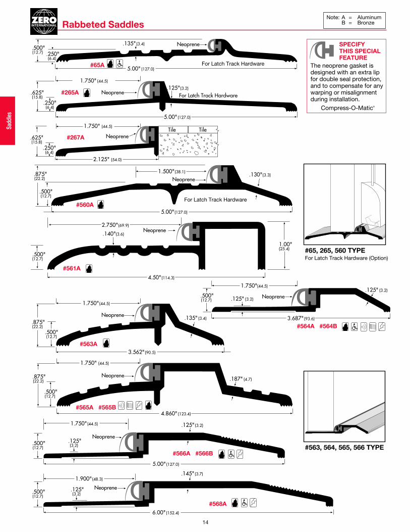
.135" (3.4) Neoprene
5.00" (127.0)
.500"(12.7) .250"
(6.4)
Rabbeted Saddles
.500"(12.7)
.187" (4.7)Neoprene
1.750" (44.5)
.875"(22.2)
4.860" (123.4)
.500"(12.7)
.135" (3.4)Neoprene
1.750"(44.5)
.875"(22.2)
3.562" (90.5)
.500"(12.7) .125" (3.2)
3.687" (93.6)
.125" (3.2)
Neoprene
1.750"(44.5)
.500"(12.7)
.125" (3.2)
Neoprene
5.00" (127.0)
1.750" (44.5)
.125"(3.2)
.130"(3.3)Neoprene
5.00"(127.0)
1.500"(38.1)
.500"(12.7)
.875"(22.2)
.500"(12.7)
.140"(3.6)Neoprene
4.50"(114.3)
1.00"(25.4)
2.750"(69.9)
.125" (3.2)
.250"(6.4)
Neoprene
1.750" (44.5)
.625"(15.8)
5.00" (127.0)
For Latch Track Hardware
#565A #565B
#563A
#564A #564B
#566A #566B
#560A
#65A
#561A
#265A
#267A
For Latch Track Hardware
#563, 564, 565, 566 TYPE
#65, 265, 560 TYPE For Latch Track Hardware (Option)
.250"(6.4)
Neoprene
1.750" (44.5)
2.125" (54.0)
.625"(15.8)
Tile TileSadd
les
For Latch Track Hardware
SPECIFY THIS SPECIAL FEATURE
The neoprene gasket isdesigned with an extra lip for double seal protection,and to compensate for anywarping or misalignmentduring installation.
Compress-O-Matic®
14
Note: A = AluminumB = Bronze
.500"(12.7)
.145" (3.7)
Neoprene
6.00" (152.4)
1.900" (48.3)
.125"(3.2)
#568A

1.875"(47.6)
Polypropylene Pile
.075"(1.8)
11°
1.125"(28.6
#96A
.250" (6.4)
.500" (12.7)
.075" (1.9)
#6 x .500" (12.7) SMS
Neoprene Lip
Note: A = Aluminum D = Dr. Bronze AnodizedB = Bronze G = Simulated Bronze AnodizedBk = Black Anodized AA = Anodized AluminumSill Protection Sweep
.195"(5.0)
Solid Neoprene
.070"(1.8)
.125"(3.2) x1.375"(34.9)
1.250"(31.8)
.500"(12.7)
#6 X .500"(12.7) SMS
.195"(4.7)
SolidNeoprene
.070"(1.8)
.125"(3.2) x2.00"(50.8)
1.250"(31.8)
1.111"(28.2)
#6 X .500" (12.7) SMS
.094"(2.4)
SolidNeoprene
.219"(5.7)
.125"(3.2) x
#6 X .500" (12.7) SMS
1.375"(34.9)
1.00"(25.4)
.750"(19.1)
.219"(5.6)
SolidNeoprene
.094"(2.4)
1.00"(25.4)
.125" (3.2) x2.00"(50.8)
#6 X .500"(12.7) SMS
1.500"(38.1)
1.00"(25.4).094"
(2.4)
SolidNeoprene
#6 x .500"(12.7) SMS
.250"(6.4)
1.00"(25.4)
#6 x .500" (12.7) SMS
.094"(2.4)
.375"(9.5)
ExtrudedBeveledNeoprene.125"(3.2) x1.00"(25.4)
Spring
#6 x .500"(12.7) SMSAdjustingScrew
.250" (6.4)
Pile with Fin Seal
.500"(12.7)
.075"(1.9)
1.019"(25.9)
11°
#6 x .500"(12.7) SMS
Pile with Fin Seal
.351"(8.9)
.881"(22.4)
Neoprene Lip
Snap-onCover
EndCap
.500"(12.7)
#39A#39D #39WA
#39WD
#339AA#339B#339G#339D
#339WAA#339WB#339WG#339WD
#329AA#329B#329G#329D
#50MA
#328AA#328B#328G#328D
#255AA#255D
#98A#98D
#100A #100D
#477AA#477D
.094"(2.4)
ExtrudedBeveledNeoprene.125"(3.2) x1.00"(25.4)
.219"(5.6)
#6 X .500"(12.7) SMS
1.00"(25.4)
.500"(12.7)
1.375"(34.9)
.375"(9.5)
Nylon Brush
.980"(24.9)
.625"(15.8)
.300"(7.6)
Nylon Brush
#8192A#8192D
#8198A#8198D#8198G
1.00"(25.4)
#6 x .750" (19.1) SMS
.094"(2.4)
.687"(17.5)
SolidNeoprene
.250"(6.4)
#539AA#539D
Neoprene Lip
.590"(15.0)
.375" (9.5)
.220"(5.6)
#8194AA
Nylon Brush
.590"(15.0)
.375" (9.5)
.220"(5.6)
#8193AA
27
Door Sw
eeps
NEWNEW
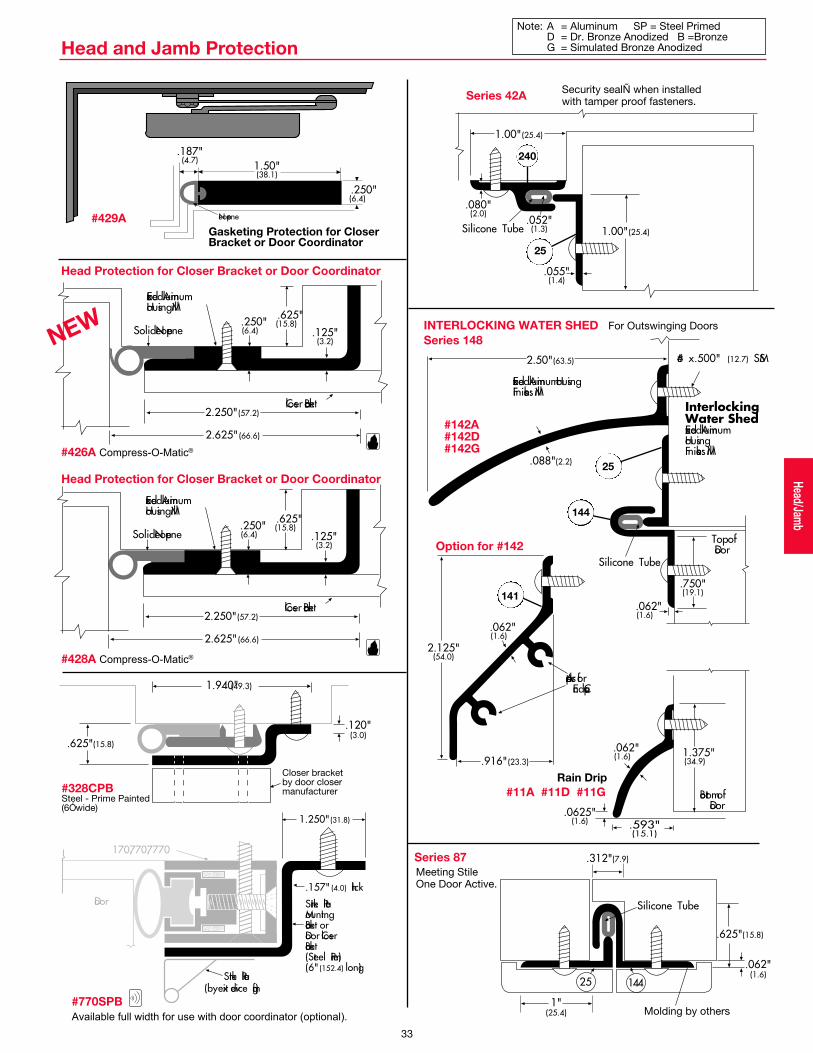
Silicone Tube
14425
.312"(7.9)
1"(25.4)
.625"(15.8)
.062"(1.6)
.080"(2.0)
.055"(1.4)
1.00"(25.4)
1.00"(25.4).052"
(1.3)Silicone Tube
.125"(3.2)
2.250"(57.2)
Extruded Aluminum Housing Mill
Closer Bracket
.625"(15.8)
Solid Neoprene
2.625" (66.6)
.250"(6.4)
Series 42A
Head Protection for Closer Bracket or Door Coordinator
#426A Compress-O-Matic®
Molding by others
Series 87
Security sealÑ when installedwith tamper proof fasteners.
240
25
2.50"(63.5)
.088"(2.2)
.750"(19.1)
.062"(1.6)
InterlockingWater ShedExtruded AluminumHousingFinishes: Mill
Extruded Aluminum HousingFinishes: Mill
#6 x .500" (12.7) SMS
Silicone Tube
Top ofDoor
2.125"(54.0)
.916"(23.3)
Adaptors forEnd Caps
.062"(1.6)
1.375"(34.9)
.062"(1.6)
.593"(15.1)
.0625"(1.6)
Bottom ofDoor
INTERLOCKING WATER SHED For Outswinging Doors
Series 148
25
144
141
Option for #142
Closer bracket by door closer manufacturer
.120"(3.0)
.625"(15.8)
1.940"(49.3)
#142A#142D#142G
#11A #11D #11G
Note: A = Aluminum SP = Steel Primed D = Dr. Bronze Anodized B =BronzeG = Simulated Bronze Anodized
Gasketing Protection for CloserBracket or Door Coordinator
1.50"(38.1)
.187"(4.7)
.250" (6.4)
Neoprene
Meeting StileOne Door Active.
#429A
Rain Drip
Head and Jamb Protection
.125"(3.2)
2.250"(57.2)
Extruded Aluminum Housing Mill
Closer Bracket
.625"(15.8)
Solid Neoprene
2.625" (66.6)
.250"(6.4)
Head Protection for Closer Bracket or Door Coordinator
#428A Compress-O-Matic®
#328CPBSteel - Prime Painted(6Ó wide)
Strike PlateMountingBracket or Door Closer Bracket (Steel Prime)(6" (152.4) long)
Strike Plate(by exit device mfg.)
Door
170,770,7770
.157" (4.0) thick
1.250" (31.8)
#770SPB
Available full width for use with door coordinator (optional).
33
Head/Jam
b
NEW

• Unique innovative design offers an all-in-one system.
• Non-handed, In-Swing or Out-Swing,
Visible or Concealed mounting.
• Configurable for Full Energy &
Low Energy applications.
• Simplified Installation & Service.
• Smooth operation, low audible noise.
• Will interface with existing
installed products.
• Heavy duty compression spring for
unparalleled door control & durability.
• Field adjustable to overcome environmental or facility changes.
ADA
Stanley’s Magic-Force™ Operator works in both Full Energy and Low Energy applications.Meets the demands for use in Supermarkets, Department Stores, Hospitals, Airports,
Office Buildings, Public Buildings, Schools, Universities and more!
HEALTHCARE GROCERY
FACTORY TESTED& PROVENPERFORMANCE
To make sure we could
deliver the Magic-Force™
Operator with all the features
to meet the demands of a
continually changing market,
we conducted the most
extensive testing yet. In
addition to testing the
Magic-Force™ Operator to
the industry standard number
of cycles, we tested it to
break it, then re-engineered
it, and re-tested to break it
again. Extensive field test-
ing confirmed Stanley’s lab
test results to prove the
Magic-Force™ performance.
The Magic-Force™ Operator
meets:
• UL Listing - UL 325
• cUL Listing - CSA 22.2 No. 247
• UL Listed Fire Door Operator
• BOCA Listing - 1017.4.3
• ICBO Report - UBC 10-1
• NFPA101 Life Safety Code -
Section 5-2.1.9
• ANSI 156.10-1998, Full Energy
• ANSI 156.19-1997, Low Energy
• CSFM - CA State Fire Marshal
As the market demands
change, the Magic-Force™
Operator is designed to
change right along with them.
This operator is setting a
new standard in the industry
and taking our customers
into the 21st century.
The Versatile Magic-Force™ Operator
RIGHT HANDLEFT HAND
LOW ENERGY FULL ENERGY
ALL-IN-ONERetrofitable Package
MAGIC-FORCE™
Access Technologies Product Group 1·800·7·ACCESS (1·800·722·2377)