Embed Size (px)
Citation preview
9556 | Phys. Chem. Chem. Phys., 2014, 16, 9556--9564 This journal is© the Owner Societies 2014
Cite this:Phys.Chem.Chem.Phys.,
2014, 16, 9556
Photophysical and structural characterisation ofin situ formed quantum dots
A. K. Bansal,a F. Antolini,b M. T. Sajjad,a L. Stroea,b R. Mazzaro,cd S. G. Ramkumar,e
K.-J. Kass,e S. Allard,e U. Scherfe and I. D. W. Samuel*a
Conjugated polymer–semiconductor quantum dot (QD) composites are attracting increasing attention
due to the complementary properties of the two classes of materials. We report a convenient method
for in situ formation of QDs, and explore the conditions required for light emission of nanocomposite
blends. In particular we explore the properties of nanocomposites of the blue emitting polymer
poly[9,9-bis(3,5-di-tert-butylphenyl)-9H-fluorene] together with cadmium sulphide (CdS) and cadmium
selenide (CdSe) precursors. We show the formation of emissive quantum dots of CdSe from thermally
decomposed precursor. The dots are formed inside the polymer matrix and have a photoluminescence
quantum yield of 7.5%. Our results show the importance of appropriate energy level alignment, and are
relevant to the application of organic–inorganic systems in optoelectronic devices.
1. Introduction
The development of low-cost solution-processable hybrid mate-rials is of increasing interest for the manufacturing of opto-electronic devices.1,2 The easy processability of conjugatedpolymers together with the tunable properties of quantum dots(QDs) makes them attractive candidates for hybrid devices.Their complementary properties have led to their use in manyapplications including: light emitting displays,3,4 solar cells,2,5
printable transistors,6 biological labeling7 and sensing.8 Todate significant attention has been paid to the use of QDsmade from metal sulphides, selenides and tellurides in opto-electronic devices fabricated using conjugated polymers due totheir high charge mobility and broad spectral coverage from thevisible to the near infrared.9 The conventional method forpreparing such a conjugated polymer–QD nanocomposite isby mixing a polymer with previously prepared nanocrystals. TheQDs are capped with ligands, and the combination of the use ofligands and surfactants confers solubility and prevents exces-sive aggregation. However, the ligand and surfactant may alsoimpede charge transport.10 This approach furthermore requiresthe use of common solvents for nanocrystal and conjugated
polymer, which can adversely affect the nanocrystal solubilityand the orientation of the polymer chains. This approach alsocan be detrimental for the homogeneity of the sample surfacequality resulting in poor device performance.11 In this paper weexplore an alternative approach in which QDs can be directlygrown inside the conductive polymer matrix itself.12,13 Theadvantage of this approach is that there is no need to performa surface ligand exchange in the growth and nucleation of theQDs. The conjugated polymer itself controls the growth ofnanoparticles and thereby removes the need for additionalcapping agents. Varying the decomposition time and tempera-ture of the molecular precursor can control the size of the QDsformed. Although this method does not allow exact control ofthe QD size and shape, it does provide intimate contactbetween the conjugated polymer and the QDs, enhancing theelectronic coupling between them. As demonstrated in recentreports, luminescent CdS nanoparticles have been successfullygrown in situ within a polystyrene matrix14,15 by thermaldecomposition of precursor or within a polymethylmetha-crylate (PMMA) matrix by laser processing.16 The in situ syntheticmethod was also employed to synthesize CdS nanoparticles inthe conducting polymer P3HT for hybrid solar cells applica-tions.13 In situ formation of light emitting dots by thermolysisof precursor inside the conjugated polymer matrix is notreported yet.
The present work is motivated by the objective to obtainefficient light emission from in situ formed QDs in the con-ductive polymer matrix for hybrid OLED as this could lead tolight-emitting devices. To do this we explore the photophysicsof precursor–conducting polymer nanocomposites by studyingthe role of the alignment of the highest occupied molecular
a Organic Semiconductor Centre, School of Physics and Astronomy, University of
St Andrews, North Haugh, St Andrews Fife, KY16 9SS, UK.
E-mail: [email protected] ENEA UTTMATF, Via Ravegnana 186, 48018 Faenza (RA), Italyc Chemistry Department ‘‘G. Ciamician’’, Bologna University, via Selmi 2,
40126 Bologna, Italyd CNR-IMM Section of Bologna, via Gobetti 101, 40129 Bologna, Italye Institut fur Polymertechnologie Bergische Universitat Wuppertal, Gauss-Strasse 20,
42097 Wuppertal, Germany
Received 18th February 2014,Accepted 1st April 2014
DOI: 10.1039/c4cp00727a
www.rsc.org/pccp
PCCP
PAPER
Ope
n A
cces
s A
rtic
le. P
ublis
hed
on 1
1 A
pril
2014
. Dow
nloa
ded
on 2
0/11
/201
4 14
:39:
32.
Thi
s ar
ticle
is li
cens
ed u
nder
a C
reat
ive
Com
mon
s A
ttrib
utio
n 3.
0 U
npor
ted
Lic
ence
.
View Article OnlineView Journal | View Issue

This journal is© the Owner Societies 2014 Phys. Chem. Chem. Phys., 2014, 16, 9556--9564 | 9557
orbital (HOMO) and lowest unoccupied molecular orbital (LUMO)levels of the organic and inorganic components. The mechanismbehind emissive QD formation has been investigated by studyingthe dominance of charge separation or energy transfer betweenpolymer and nanocrystals in the nanocomposites.
In this paper, the blue emitting polymer poly[9,9-bis(3,5-di-tert-butylphenyl)-9H-fluorene], PBPFO, (see Fig. 1(a)) wasselected because of its high thermal stability. It was studiedwith precursors cadmium diethylxanthate (CdDEX) and cadmium-2-(N,N-dimethylamino)ethylselenolate CdDAMSe (Fig. 1(b) and (c))that can be thermally converted to CdS and CdSe respectively.Hence nanocomposite films could be made by blending one of theprecursors with the polymer, followed by heating. The formationof the CdS/CdSe QDs in the polymer matrix was studied byabsorption and photoluminescence measurements and additionalunderstanding of the QD growth and quality was achieved by high-resolution transmission electron microscopy (TEM) techniques.
The paper is organized as follows. First, we discuss thephotophysical properties of the polymer itself. Second, thermo-lysis properties of precursors are discussed using TEM andabsorption and emission results. Finally, the detailed trans-formation of the precursor molecules into CdS/CdSe nano-particles in the polymer matrix during the thermolysis processis explained. In the discussion, we rationalize the molecularmechanism of the emissive nanoparticle formation based onenergy level alignment of donor and acceptor.
2. Materials and methods2.1 Materials synthesis and film preparation
PBPFO homo-polymer was synthesized as reported in the litera-ture17 with minor modifications. Specifically it was synthesizedin a Yamamoto-type cross coupling reaction under microwaveconditions, using the monomer 2,7-dibromo-9,9-bis(3,5-di-tert-butylphenyl)-9H-fluorene. The polymer has an average molecularweight of Mn = 10 400 and Mw = 18 500. The monomer itself wassynthesized using 2,7-dibromofluorenone in four steps with anoverall yield of 45%. Thermogravimetric analysis (TGA) of the
polymer has showed it was stable up to 400 1C. The CdSprecursor cadmium diethylxanthate (CdDEX) was synthesizedas reported in the literature18 with minor changes. Specificallythe synthesis is performed in the presence of 2,20-bipyridyl(bipyridyl) acting as additional chelating ligand. This precursorbelongs to the metal xanthate family, which are known todecompose cleanly at low temperatures into metal sulphide,here by generating only volatile side products.19 The bipyridylligand in this precursor enables sufficient solubility of thexanthate in common organic solvents which otherwise wouldbe insoluble. The protocol for the synthesis of the CdSe precursorcadmium-2-(N,N-dimethylamino)ethylselenolate (CdDMASe) wasadapted from the work20 of Kedarnath et al. It involved firstmaking of an aliphatic diselenide compound and then reactingit with a Cd[II] salt to give the metalorganic precursor. For CdSethis single source precursor binds two Me2NCH2CH2Se fragments,leading to good solubility, clean thermal decomposition undergeneration of cadmium selenide (CdSe) QDs. Both precursors aresoluble in toluene, stable at room temperature conditions and canbe stored for weeks.
Neat films of the precursor alone and of nanocompositefilms of polymer–precursor blend were prepared by spin coat-ing from toluene solution at 1500 rpm onto fused silicasubstrates. The film used for spin-coating consisted of eitherprecursor powder alone or precursor/polymer in ratio of 4 : 1 intoluene solvent at 50 mg ml�1 concentration. As prepareduniform films were baked at different temperatures inside alow vacuum 8 � 10�2 mbar for thermolysis.
2.2 Photophysical and structural measurements
The solution photoluminescence quantum yield (PLQY) of thepolymer was measured by a relative method using quininesulfate in 0.5 M sulfuric acid, which has a PLQY of 0.546,21 asthe standard. Photoluminescence spectra were recorded in a JYHoriba Fluoromax 2 fluorimeter, with the solutions excited at360 nm. The optical densities of the standard and sample weresimilar and small (B0.1). The accuracy of these PLQY measure-ments is estimated to be �10% of the stated value. Solid-statePLQY measurements of thin films were measured in an inte-grating sphere under a nitrogen purge22 in a HamamatsuC9920-02 luminescence measurement system.
For time-resolved fluorescence measurements samples wereexcited with 100 fs light pulses at 385 nm from the secondharmonic of a Ti:sapphire oscillator (Spectra-Physics Mai-Tai) out-put at 80 MHz. The emission from the samples was passed througha long-pass filter to remove the remaining excitation light andfocused onto the slit of a spectrograph (Chromex 250i). The outputfrom the spectrograph was time-resolved with a Hamamatsu streakcamera operating in synchroscan mode. The fluorescence decayswere captured on a number of time ranges of the streak camera toensure that any initial decay was resolved to a resolution of 2 ps.The excitation density used was 5 nJ cm�2 or less to make sure allmeasurements were within the linear regime of the response.
The transmission electron microscopy (TEM) measurementswere performed with a Philips Tecnai F20 Schottky Field emissiongun (FEG) instrument operating at 200 kV. The images were
Fig. 1 Molecular structure of (a) poly[9,9-bis(3,5-di-tert-butylphenyl)-9H-fluorene] (PBPFO) polymer and (b) CdDEX and (c) CdDMASe precursor.
Paper PCCP
Ope
n A
cces
s A
rtic
le. P
ublis
hed
on 1
1 A
pril
2014
. Dow
nloa
ded
on 2
0/11
/201
4 14
:39:
32.
Thi
s ar
ticle
is li
cens
ed u
nder
a C
reat
ive
Com
mon
s A
ttrib
utio
n 3.
0 U
npor
ted
Lic
ence
.View Article Online
9558 | Phys. Chem. Chem. Phys., 2014, 16, 9556--9564 This journal is© the Owner Societies 2014
processed with Digital micrograph and ImageJ software. The QDsize was determined manually on the basis of the obtained high-resolution transmission electron microscope (HRTEM) images. Thechemical composition was verified by means of energy dispersivespectrometry (EDS) with an EDAX Phoenix spectrometer equippedwith an ultra-thin window detector and TEM image and analysissoftware. The samples for TEM characterization were depositedover a TEM grid with spin-coating using the same conditions.Copper TEM grids covered by Quantifoils Holey Carbon film wereused to maximize the area of the freestanding sample.
3. Results and discussion3.1 Photophysical properties of polymer
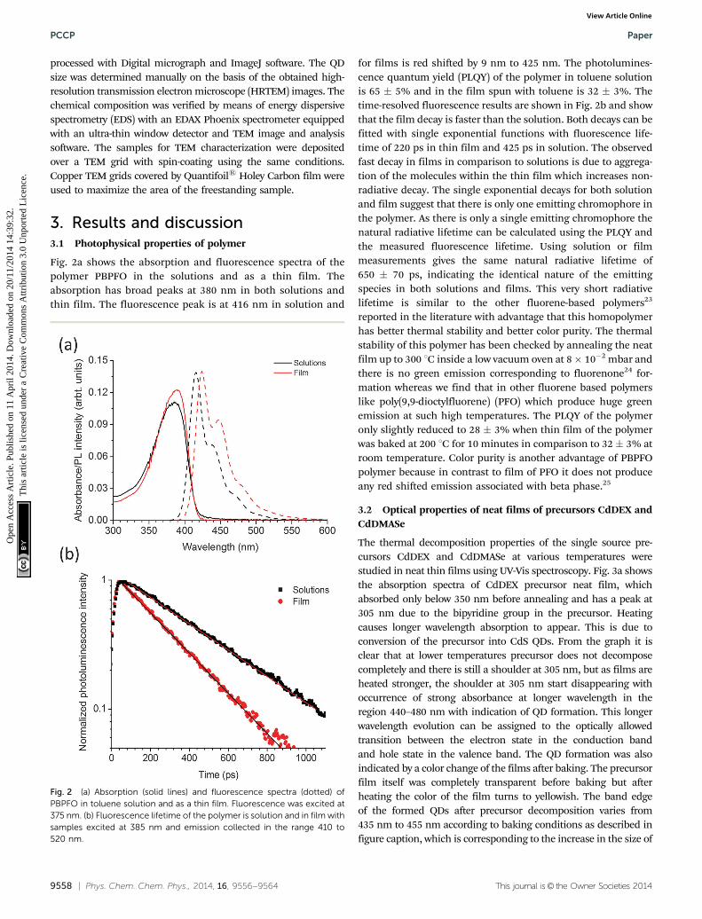
Fig. 2a shows the absorption and fluorescence spectra of thepolymer PBPFO in the solutions and as a thin film. Theabsorption has broad peaks at 380 nm in both solutions andthin film. The fluorescence peak is at 416 nm in solution and
for films is red shifted by 9 nm to 425 nm. The photolumines-cence quantum yield (PLQY) of the polymer in toluene solutionis 65 � 5% and in the film spun with toluene is 32 � 3%. Thetime-resolved fluorescence results are shown in Fig. 2b and showthat the film decay is faster than the solution. Both decays can befitted with single exponential functions with fluorescence life-time of 220 ps in thin film and 425 ps in solution. The observedfast decay in films in comparison to solutions is due to aggrega-tion of the molecules within the thin film which increases non-radiative decay. The single exponential decays for both solutionand film suggest that there is only one emitting chromophore inthe polymer. As there is only a single emitting chromophore thenatural radiative lifetime can be calculated using the PLQY andthe measured fluorescence lifetime. Using solution or filmmeasurements gives the same natural radiative lifetime of650 � 70 ps, indicating the identical nature of the emittingspecies in both solutions and films. This very short radiativelifetime is similar to the other fluorene-based polymers23
reported in the literature with advantage that this homopolymerhas better thermal stability and better color purity. The thermalstability of this polymer has been checked by annealing the neatfilm up to 300 1C inside a low vacuum oven at 8� 10�2 mbar andthere is no green emission corresponding to fluorenone24 for-mation whereas we find that in other fluorene based polymerslike poly(9,9-dioctylfluorene) (PFO) which produce huge greenemission at such high temperatures. The PLQY of the polymeronly slightly reduced to 28 � 3% when thin film of the polymerwas baked at 200 1C for 10 minutes in comparison to 32 � 3% atroom temperature. Color purity is another advantage of PBPFOpolymer because in contrast to film of PFO it does not produceany red shifted emission associated with beta phase.25
3.2 Optical properties of neat films of precursors CdDEX andCdDMASe
The thermal decomposition properties of the single source pre-cursors CdDEX and CdDMASe at various temperatures werestudied in neat thin films using UV-Vis spectroscopy. Fig. 3a showsthe absorption spectra of CdDEX precursor neat film, whichabsorbed only below 350 nm before annealing and has a peak at305 nm due to the bipyridine group in the precursor. Heatingcauses longer wavelength absorption to appear. This is due toconversion of the precursor into CdS QDs. From the graph it isclear that at lower temperatures precursor does not decomposecompletely and there is still a shoulder at 305 nm, but as films areheated stronger, the shoulder at 305 nm start disappearing withoccurrence of strong absorbance at longer wavelength in theregion 440–480 nm with indication of QD formation. This longerwavelength evolution can be assigned to the optically allowedtransition between the electron state in the conduction bandand hole state in the valence band. The QD formation was alsoindicated by a color change of the films after baking. The precursorfilm itself was completely transparent before baking but afterheating the color of the film turns to yellowish. The band edgeof the formed QDs after precursor decomposition varies from435 nm to 455 nm according to baking conditions as described infigure caption, which is corresponding to the increase in the size of
Fig. 2 (a) Absorption (solid lines) and fluorescence spectra (dotted) ofPBPFO in toluene solution and as a thin film. Fluorescence was excited at375 nm. (b) Fluorescence lifetime of the polymer is solution and in film withsamples excited at 385 nm and emission collected in the range 410 to520 nm.
PCCP Paper
Ope
n A
cces
s A
rtic
le. P
ublis
hed
on 1
1 A
pril
2014
. Dow
nloa
ded
on 2
0/11
/201
4 14
:39:
32.
Thi
s ar
ticle
is li
cens
ed u
nder
a C
reat
ive
Com
mon
s A
ttrib
utio
n 3.
0 U
npor
ted
Lic
ence
.View Article Online

This journal is© the Owner Societies 2014 Phys. Chem. Chem. Phys., 2014, 16, 9556--9564 | 9559
the CdS nanoparticles. A similar study was performed for theCdDMASe precursor, and the resulting absorption spectra areshown in Fig. 3b. This precursor is also transparent above400 nm before baking but after heating absorption develops atlonger wavelength. This is due to the formation of CdSe QDs, andthe onset wavelength of the absorption is in the range460�520 nm, depending on the baking conditions. The neat filmsof both precursors before and after baking were also studied withfluorescence spectroscopy, where samples were excited at 320 nmfor CdDEX precursor and 380 nm for CdDMASe precursor and alsoat absorption band edge of each baked film, but no fluorescenceemission obtained.
3.3 Structural characterisation of neat films of precursorsCdDEX and CdDMASe
To obtain further evidence of nanoparticle growth and nuclea-tion, transmission electron microscopy (TEM) measurementswere performed. These analyses were carried out on filmsdeposited and annealed directly on a TEM grid. The TEM images
of the films before baking did not show any of the crystallinestructures ascribable to the CdS or CdSe QDs. However, theformation of CdS QDs (Fig. 3c) and CdSe QDs (Fig. 3d) wasvisible in the films which had been baked. Fig. 3c shows anexample of the TEM results in which a neat film of precursorCdDEX was heated at 150 1C for 10 minutes under low vacuumconditions. The high-resolution image shows the QD distribu-tion in the film that forms clusters of 6–7 QDs with the presenceof both the cubic and the hexagonal crystal phase in the QDpopulation. The average size of the CdS QDs is 4.9 nm with astandard deviation of 0.9 nm and is in the range of reportedliterature values26 of CdS QD sizes. Fig. 3d shows the highresolution TEM results for CdDMASe precursor film baked at160 1C for 10 minutes, which evidenced mono-dispersed crystal-line QD in clusters of 5–10 CdSe QDs. The analysis of the averagesize determined on 70 single QDs gives an average diameter of4.5 nm of nanocrystals and which is below the threshold of theBohr exciton radius for CdSe.10
The above results indicate that there is nucleation andgrowth of CdS and CdSe QDs but fluorescence spectroscopyshows they are non-emissive. A likely reason for the lack ofemission from the QDs formed might be due to lack ofpassivation27 of the surface of the QDs. As there is no cappingagent, surface traps dominate due to S or Se ions, and this leadsto non-radiative decay of the excited states. To investigate thisfurther, we blended the precursors into the polymer matrix, asdiscussed in the next section.
3.4 Optical properties of nanocomposite film of polymer andCdDEX precursor
In the nanocomposites the polymer and precursor wereblended in a weight/weight ratio of 1 : 4 respectively. Fig. 4shows the absorption and fluorescence spectra of the polymer–precursor CdDEX nanocomposites films before and afterannealing at different temperatures from 140 1C to 180 1C. Itis evident from Fig. 4a that before baking the nanocompositefilms the absorption spectra has contributions from both thepolymer and precursor. The shoulder at 380 nm is due to thep–p* transition of the polymer, and the peak at 305 nm (notshown) is due to the bipyridine on the precursor (as discussedearlier in Fig. 3a). After baking the blend films at selectedtemperatures, there is an evolution of the shoulder at 450 nm.The shift of the shoulder towards longer wavelength at higherbaking temperature indicates an increase in nanocrystal sizeand concentration. The absence of well-resolved peak likestructures can be attributed to the polydispersity28 of QD size.These results show that the precursor decomposed and QDsformed similar to neat precursor film as explained in earliersection. Fig. 4b shows the fluorescence spectra of the nano-composite films where blend films were excited at 375 nm. Theresults indicate that in the blend before baking the fluores-cence spectrum is similar to that of neat polymer film as shownin Fig. 2a with all emission coming from polymer itself. Afterbaking the blend films at different temperatures the spectrabecome narrower with sharp peaks at longer wavelengths inannealed films. This may happen due to polymer chain
Fig. 3 Absorption spectra of (a) CdDEX and (b) CdDMASe precursor before(dash dotted line) and after baking at one of 3 different temperatures 150 1C(dashed line), 160 1C (dotted line) and 180 1C (solid line) for 10 minutes. Highresolution transmission electron microscope (HRTEM) images of the (c) CdDEXand (d) CdDMAse precursor thin films after baking at 150 1C for 10 minutes.
Paper PCCP
Ope
n A
cces
s A
rtic
le. P
ublis
hed
on 1
1 A
pril
2014
. Dow
nloa
ded
on 2
0/11
/201
4 14
:39:
32.
Thi
s ar
ticle
is li
cens
ed u
nder
a C
reat
ive
Com
mon
s A
ttrib
utio
n 3.
0 U
npor
ted
Lic
ence
.View Article Online

9560 | Phys. Chem. Chem. Phys., 2014, 16, 9556--9564 This journal is© the Owner Societies 2014
reorganisation at higher annealing temperatures. There is noemission corresponding to the QD formation even though thereis overlap of the PL spectrum of the polymer with the absorptionspectrum of the CdS QDs, so it should favour long-range energytransfer from polymer to QDs. The PLQY was also measured in theblend before and after annealing when the sample has beenexcited at 375 nm. Before baking the PLQY of the polymer is only2.7%, compared with 32% for a neat film of the polymer. Afterbaking it remains approximately 2.5% like before annealing thenanocomposites film, even though at higher temperatures theprecursor mostly decomposed in the blended system. Theseresults indicate that precursor works as a quencher in the nano-composite films even though it does not absorb much at theselected excitation wavelength. To understand the quenching afterbaking, TEM studies were performed on the nanocomposite.
3.5 Structural characterization of nanocomposite film ofpolymer and CdDEX precursor
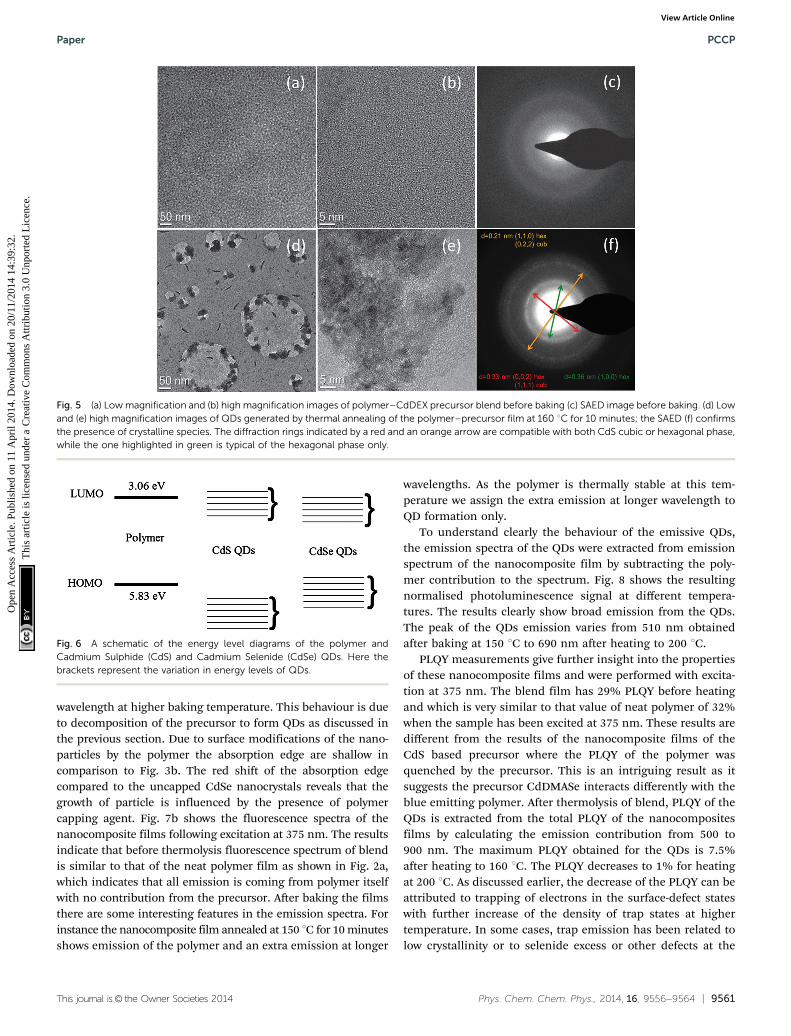
The particle size and crystalline structure of the formed QDs inthe nanocomposites films after baking were investigated byTEM studies and are shown in Fig. 5. Both low and high
magnification micrographs (Fig. 5a and b respectively) beforeheating the nanocomposite show that the organic–inorganicmatrix is uniformly distributed over the carbon film and noaggregates of QDs are observable under these conditions. TheSAED (Selected Area Electron Diffraction) in Fig. 5c also showsthat in the sample crystalline particles are absent and theobserved radial distribution is typical of the polymer only.Fig. 5d shows a low magnification image of the nanocompositefilm after heating the film at 160 1C for 10 minutes. The resultsshow that there is the formation of nanocrystals in the polymermatrix and these particles within the polymer tend to aggregatein clusters with a size between 20–60 nm. The HREM image inFig. 5e show the particle size is between 3 and 6 nm. Applyingthe FFT algorithm to the HREM images it was possible torecognize the typical periodicity of CdS hexagonal phase. Forfurther confirmation, the SAED can be indexed as hexagonalCdS as shown in Fig. 5f. It is not possible to exclude the cubicphase because the reflections of the two phases overlap.
The absorption and TEM results show that nanoparticlesform and yet there is no fluorescence from the nanoparticlesin the blend. Possible explanations could be that the nano-particles are either non-emissive or energy transfer does notoccur to them from the polymer. Non-emissive QDs can beformed if they are not passivated well or if they form clusters inwhich aggregation leads to quenching of the QD emission. Asthe nucleation and growth of the CdS particle was inside thepolymer matrix13 so we can rule out this scenario of non-passivation of QDs. TEM results show the formation of clustersso it might be possible for emission quenching due to aggrega-tion of QDs. No energy transfer from polymer to the CdSnanocrystal is the likely phenomena. Fig. 6 shows the energylevels of the polymer from cyclic voltammetry and CdS QDsfrom literature. The HOMO of the polymer is at 5.83 eV and theLUMO is at 3.06 eV. The energy level band for CdS nano-particles is shown based on literature values.29,30 This scenariosuggests the type 2 energy level alignment between the polymerand thermally decomposed CdS QDs. In this case as reported byLutich et al. there is a possibility of competition between chargeseparation and energy transfer and their dominance stronglydepends on the nanoscale geometry of the system.31 In oursystem thermolysis of precursor occurs inside the polymermatrix so there is no hindrance of minimum separation dueto surface ligands between the nanocrystal core and the poly-mer molecules. As there is no minimum separation so itfavours the occurrence of the charge transfer and limits theefficiency of energy transfer, and that define the non-emissivebehaviour of the QDs in this particular system.
3.6 Optical properties of nanocomposite film of polymer andCdDMASe precursor
Fig. 7 shows the absorption and fluorescence spectra of thenanocomposite films prepared using polymer with CdDMASeprecursor. Before annealing the absorption spectrum is domi-nated by the polymer, with a small contribution at shorterwavelengths from the precursor. After baking a shoulder appearsin the region of 450 nm, which grows, and shifts towards longer
Fig. 4 (a) Absorption (b) fluorescence spectra of the CdDEX precursor–polymer blend film before baking (solid line) and after annealing at3 different temperatures 140 1C (dashed line), 160 1C (dotted line) and180 1C (dash dotted line) each for 10 minutes. Samples were excited at 375 nm.
PCCP Paper
Ope
n A
cces
s A
rtic
le. P
ublis
hed
on 1
1 A
pril
2014
. Dow
nloa
ded
on 2
0/11
/201
4 14
:39:
32.
Thi
s ar
ticle
is li
cens
ed u
nder
a C
reat
ive
Com
mon
s A
ttrib
utio
n 3.
0 U
npor
ted
Lic
ence
.View Article Online
This journal is© the Owner Societies 2014 Phys. Chem. Chem. Phys., 2014, 16, 9556--9564 | 9561
wavelength at higher baking temperature. This behaviour is dueto decomposition of the precursor to form QDs as discussed inthe previous section. Due to surface modifications of the nano-particles by the polymer the absorption edge are shallow incomparison to Fig. 3b. The red shift of the absorption edgecompared to the uncapped CdSe nanocrystals reveals that thegrowth of particle is influenced by the presence of polymercapping agent. Fig. 7b shows the fluorescence spectra of thenanocomposite films following excitation at 375 nm. The resultsindicate that before thermolysis fluorescence spectrum of blendis similar to that of the neat polymer film as shown in Fig. 2a,which indicates that all emission is coming from polymer itselfwith no contribution from the precursor. After baking the filmsthere are some interesting features in the emission spectra. Forinstance the nanocomposite film annealed at 150 1C for 10 minutesshows emission of the polymer and an extra emission at longer
wavelengths. As the polymer is thermally stable at this tem-perature we assign the extra emission at longer wavelength toQD formation only.
To understand clearly the behaviour of the emissive QDs,the emission spectra of the QDs were extracted from emissionspectrum of the nanocomposite film by subtracting the poly-mer contribution to the spectrum. Fig. 8 shows the resultingnormalised photoluminescence signal at different tempera-tures. The results clearly show broad emission from the QDs.The peak of the QDs emission varies from 510 nm obtainedafter baking at 150 1C to 690 nm after heating to 200 1C.
PLQY measurements give further insight into the propertiesof these nanocomposite films and were performed with excita-tion at 375 nm. The blend film has 29% PLQY before heatingand which is very similar to that value of neat polymer of 32%when the sample has been excited at 375 nm. These results aredifferent from the results of the nanocomposite films of theCdS based precursor where the PLQY of the polymer wasquenched by the precursor. This is an intriguing result as itsuggests the precursor CdDMASe interacts differently with theblue emitting polymer. After thermolysis of blend, PLQY of theQDs is extracted from the total PLQY of the nanocompositesfilms by calculating the emission contribution from 500 to900 nm. The maximum PLQY obtained for the QDs is 7.5%after heating to 160 1C. The PLQY decreases to 1% for heatingat 200 1C. As discussed earlier, the decrease of the PLQY can beattributed to trapping of electrons in the surface-defect stateswith further increase of the density of trap states at highertemperature. In some cases, trap emission has been related tolow crystallinity or to selenide excess or other defects at the
Fig. 5 (a) Low magnification and (b) high magnification images of polymer–CdDEX precursor blend before baking (c) SAED image before baking. (d) Lowand (e) high magnification images of QDs generated by thermal annealing of the polymer–precursor film at 160 1C for 10 minutes; the SAED (f) confirmsthe presence of crystalline species. The diffraction rings indicated by a red and an orange arrow are compatible with both CdS cubic or hexagonal phase,while the one highlighted in green is typical of the hexagonal phase only.
Fig. 6 A schematic of the energy level diagrams of the polymer andCadmium Sulphide (CdS) and Cadmium Selenide (CdSe) QDs. Here thebrackets represent the variation in energy levels of QDs.
Paper PCCP
Ope
n A
cces
s A
rtic
le. P
ublis
hed
on 1
1 A
pril
2014
. Dow
nloa
ded
on 2
0/11
/201
4 14
:39:
32.
Thi
s ar
ticle
is li
cens
ed u
nder
a C
reat
ive
Com
mon
s A
ttrib
utio
n 3.
0 U
npor
ted
Lic
ence
.View Article Online

9562 | Phys. Chem. Chem. Phys., 2014, 16, 9556--9564 This journal is© the Owner Societies 2014
interface of the nanocrystals. However, band edge and trapemissions are often observed together in CdSe nanocrystals.Increasing the amount of surface defects of the nanoparticlescan enhance enormously the trap state emission with respect tothe band-edge recombination mechanism that can be comple-tely suppressed. The other scenario of reduction in PLQY mightbe due to aggregate of the QDs at the higher annealingtemperature, which has been investigated by TEM studies.
3.7 Structural characterization of nanocomposite film ofpolymer and CdDMASe precursor
TEM images of nanocomposite films at medium and highmagnification are shown in Fig. 9. Image 9a shows that heatingto 160 1C for 10 minutes leads to the formation of particles inthe polymer matrix. From the HREM micrograph displayed inFig. 9b it is clear that most of the particles are well dispersedand have a diameter about 4 to 8 nm, but there is also apopulation of aggregated clusters, containing from 5 to10 units. The particle size is smaller or in the similar range ofthe uncapped QDs shown earlier in Section 3.2. Fig. 9c and dshows the TEM results of the film baked at 180 1C for10 minutes and it is clear from the figure that the particlestarts to aggregate under these annealing conditions by makingclusters of 20–30 units. SAED analysis (not reported) shows forboth the annealed samples the presence of crystalline CdSewith a mixture of hexagonal and cubic phase. Aggregate for-mation at higher baking temperature explains the reduction inthe PLQY of the emissive QDs at higher temperatures.
Fig. 7 (a) Absorption (b) fluorescence spectra of the precursor CdDMAse–polymer blend film before baking (solid line) and after annealing at 4different temperatures 150 1C (dashed line), 160 1C (dotted line), 180 1C(dash dotted line) and 200 1C (dash double dotted line) each for 10 minutes.Samples were excited at 375 nm.
Fig. 8 Emission spectrum of QDs obtained after subtracting the polymercontribution from the polymer–precursor nanocomposite annealed attemperatures 150 1C (dashed line), 160 1C (dotted line), 180 1C (dashdotted line) and 200 1C (dash double dotted line) each for 10 minutes.
Fig. 9 (a) Medium and (b) high magnification images of QDs generated by10 minutes of thermal annealing at 160 1C of the polymer–CdAMSeprecursor film. (c) Medium and (d) high magnification images of QDsgenerated by 10 minutes of thermal annealing at 180 1C of the polymer–precursor film.
PCCP Paper
Ope
n A
cces
s A
rtic
le. P
ublis
hed
on 1
1 A
pril
2014
. Dow
nloa
ded
on 2
0/11
/201
4 14
:39:
32.
Thi
s ar
ticle
is li
cens
ed u
nder
a C
reat
ive
Com
mon
s A
ttrib
utio
n 3.
0 U
npor
ted
Lic
ence
.View Article Online

This journal is© the Owner Societies 2014 Phys. Chem. Chem. Phys., 2014, 16, 9556--9564 | 9563
The behaviour of these nanocomposite films is completelydifferent from those made from the other precursor. This canbe understood in terms of the energy levels. Efficient transferhas been observed from conjugated polymers to colloidalsemiconductor QD in several reports with having comparisonof short and long chain ligands,32 dopant concentration incore–shell nanoparticles33 and the dominance of long-rangeenergy transfer has been reported in them.34 In our results onthe basis of energy level alignment of polymer and QDs we canidentify the dominant mechanism. Fig. 6 shows the positionof the energy levels of CdSe QDs taken from the litera-ture11,35,36 with respect to polymer energy levels. This scenariosuggests type 1 energy level alignment between polymer andCdSe nanocrystals. As discussed earlier in our system thermo-lysis of precursor occurs inside the polymer matrix so there isno minimum separation due to surface ligands between thenanocrystal core and the polymer molecules so it favours theoccurrence of the charge transfer/Dexter type energy transfer.We know that to allow the simultaneous injection of electronand hole to the donor, Dexter type energy transfer requirestype-I alignment of HOMO and LUMO levels of the donor–acceptor. This scenario suggests that we have Dexter typeenergy transfer from polymer to the QDs. But there is goodspectral overlap of polymer emission with absorbance of theQDs so there is a possibility of long-range energy transfersas well.
4. Conclusions
In summary, we have demonstrated the in situ formation ofQDs inside the conjugated polymer matrix. We show that thepolymer PBPFO having solid state PLQY up to 32% and naturalradiative lifetime of 650 ps is suitable for thermolysis of QDsdue to its excellent thermal stability. Our studies show that thethermal decomposition of the precursor CdDEX and CdDAMSeinside a polymer matrix produces different characteristics ofthe QDs due to differences in energy level alignment. We alsodescribe here the use of time and temperature to achieve size(and spectroscopic) tuning of the final particles. Our resultsshow that in situ emissive QDs can be made inside the con-jugated polymer matrix and in our studied system, a PLQYof CdSe QDs of 7.5% is achieved. Our results open up thepossibility for laser writing of emissive QDs in optoelectronicdevices.
Acknowledgements
We acknowledge financial support from FP7 project ‘‘LaserInduced Synthesis of Polymeric Nanocomposite Materials andDevelopment of Micro-patterned Hybrid Light Emitting Diodes(LED) and Transistors (LET)’’ – LAMP project (G.A. 247928).AKB and IDWS also acknowledge financial support from EPSRCProgramme grant ‘‘Challenging the limits of photonics: Struc-tured light’’ EP/J01771X/1.
References
1 W. U. Huynh, J. J. Dittmer and A. P. Alivisatos, Science, 2002,295, 2425.
2 A. L. Briseno, T. W. Holcombe, A. I. Boukai, E. C. Garnett,S. W. Shelton, J. J. M. Frechet and P. Yang, Nano Lett., 2010,10, 334.
3 S. Coe, W. K. Woo, M. Bawendi and V. Bulovis, Nature, 2002,420, 800.
4 N. Tessler, V. Medvedev, M. Kazes, S. H. Kan and U. Banin,Science, 2002, 295, 1506.
5 S. Dayal, N. Kopidakis, D. C. Olson, D. S. Ginley andG. Rumbles, Nano Lett., 2010, 10, 239–242.
6 F. Hetsch, N. Zhao, S. V. Kershaw and A. L. Rogach, Mater.Today, 2013, 16, 312–325.
7 S. J. Rosenthal, J. C. Chang, O. Kovtun, J. R. McBride andI. D. Tomlison, Chem. Biol., 2011, 18, 10–24.
8 H. Dhyani, C. Dhand, B. D. Malhotra and P. Sen, J. Biosens.Bioelectron., 2011, 3, 112.
9 P. O. Anikeeva, J. E. Halpert, M. G. Bawendi and V. Bulovic,Nano Lett., 2009, 9, 2532–2536.
10 A. M. Smith and S. Nie, Acc. Chem. Res., 2010, 43, 190–200.11 C. Querner, P. Reiss, S. Sadki, M. Zagorskab and A. Pron,
Phys. Chem. Chem. Phys., 2005, 7, 3204–3209.12 H. C. Leventis, S. P. King, A. Sudlow, M. S. Hill, K. C. Molloy
and S. A. Haque, Nano Lett., 2010, 10, 1253–1258.13 N. Bansal, L. X. Reynolds, A. MacLachlan, T. Lutz, R. S.
Ashraf, W. Zhang, C. B. Nielsen, I. McCulloch, D. G. Rebois,T. Kirchartz, M. S. Hill, K. C. Molloy, J. Nelson and S. A.Haque, Sci. Rep., 2013, 3, 1531.
14 F. Antolini, T. Di Luccio, A. M. Laera, L. Mirenghi, E. Piscopiello,M. Re and L. Tapfer, Phys. Status Solidi B, 2007, 244, 2768–2781.
15 F. Antolini, E. Burresi, L. Stroea, V. Morandi, L. Ortolani,G. Accorsi and M. Blosi, J. Nanomater., 2012, 2012, 1–11.
16 V. Resta, A. M. Laera, A. Camposeo, E. Piscopiello, L. Persano,D. Pisignano and L. Tapfer, J. Phys. Chem. C, 2012, 116,25119–25125.
17 S. Setayesh, A. C. Grimsdale, T. Weil, V. Enkelmann, K. Mullen,F. Meghdadi, E. J. W. List and G. Leising, J. Am. Chem. Soc.,2001, 123, 946–953.
18 D. Barreca, A. Gasparotto, C. Maragno, R. Seraglia, E. Tondello,A. Venzo, V. Krishnan and H. Bertagnolli, Appl. Organomet.Chem., 2005, 19, 59–67.
19 N. Pradhan, B. Katz and S. Efrima, J. Phys. Chem. B, 2003,107, 13843–13854.
20 G. Kedarnath, S. Dey, V. K. Jain, G. K. Dey and B. Varghese,Polyhedron, 2006, 25, 2383–2391.
21 A. N. Fletcher, Photochem. Photobiol., 1969, 9, 439–444.22 N. C. Greenham, I. D. W. Samuel, G. R. Hyes, R. T. Philips,
Y. A. R. Kessener, S. C. Moratti, A. B. Holmes and R. H. Friend,Chem. Phys. Lett., 1995, 241, 89–96.
23 F. Laquai, A. K. Mishra, M. R. Ribas, A. Petrozza, J. Jacob,L. Akcelrud, K. Mullen, R. H. Friend and G. Wegner,Adv. Funct. Mater., 2007, 17, 3231–3240.
24 K. Becker, J. M. Lupton, J. Feldmann, B. S. Nehls, F. Galbrecht,D. Gao and U. Scherf, Adv. Funct. Mater., 2006, 16, 364–370.
Paper PCCP
Ope
n A
cces
s A
rtic
le. P
ublis
hed
on 1
1 A
pril
2014
. Dow
nloa
ded
on 2
0/11
/201
4 14
:39:
32.
Thi
s ar
ticle
is li
cens
ed u
nder
a C
reat
ive
Com
mon
s A
ttrib
utio
n 3.
0 U
npor
ted
Lic
ence
.View Article Online
9564 | Phys. Chem. Chem. Phys., 2014, 16, 9556--9564 This journal is© the Owner Societies 2014
25 A. K. Bansal, A. Ruseckas, P. E. Shaw and I. D. W. Samuel,J. Phys. Chem. C, 2010, 114, 17864–17867.
26 T. Rath and G. Trimmel, Hybrid Mater., 2013, 3, 15–36.27 S. Kango, S. Kaila, A. Celli, J. Njuguna, Y. Habibi and
R. Kumar, Prog. Polym. Sci., 2013, 38, 1232–1261.28 D. Zhitomirsky, I. J. Kramer, A. J. Labelle, A. Fischer,
R. Debnath, J. Pan, O. M. Bakr and E. H. Sargent, NanoLett., 2012, 12, 1007–1012.
29 S. K. Haram, B. M. Quinn and A. J. Bard, J. Am. Chem. Soc.,2001, 123, 8860–8861.
30 C. Yang, A. Tang and F. Teng, J. Electrochem. Soc., 2013, 160,H121–H125.
31 A. A. Lutich, G. Jiang, A. S. Susha, A. L. Rogach, F. D. Stefaniand J. Feldmann, Nano Lett., 2009, 9, 2636–2640.
32 T.-W. F. Chang, S. Musikhin, L. Bakueva, L. Levina, M. A. Hines,P. W. Cyr and E. H. Sargent, Appl. Phys. Lett., 2004, 84, 4295.
33 M. Anni, L. Manna, R. Cingolani, D. Valerini, A. Creti andM. Lomascolo, Appl. Phys. Lett., 2004, 85, 4169–4171.
34 T. Stoferle, U. Scherf and R. F. Mahrt, Nano Lett., 2009, 9,453–456.
35 M. Amelia, C. Lincheneau, S. Silvi and A. Credi, Chem. Soc.Rev., 2012, 41, 5728–5743.
36 C. B. Murray, D. J. Norris and M. G. Bawendi, J. Am. Chem.Soc., 1993, 115, 8706–8715.
PCCP Paper
Ope
n A
cces
s A
rtic
le. P
ublis
hed
on 1
1 A
pril
2014
. Dow
nloa
ded
on 2
0/11
/201
4 14
:39:
32.
Thi
s ar
ticle
is li
cens
ed u
nder
a C
reat
ive
Com
mon
s A
ttrib
utio
n 3.
0 U
npor
ted
Lic
ence
.View Article Online