Embed Size (px)
Citation preview
Route Survey Manual State of Vermont Agency of Transportation Version 2008

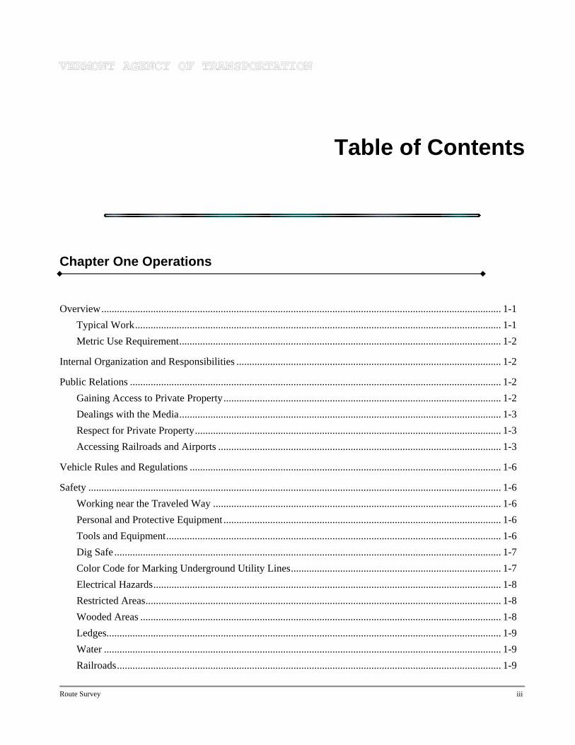
Table of Contents
Chapter One Operations
Overview.......................................................................................................................................................... 1-1 Typical Work............................................................................................................................................. 1-1 Metric Use Requirement............................................................................................................................ 1-2
Internal Organization and Responsibilities ...................................................................................................... 1-2
Public Relations ............................................................................................................................................... 1-2 Gaining Access to Private Property........................................................................................................... 1-2 Dealings with the Media............................................................................................................................ 1-3 Respect for Private Property...................................................................................................................... 1-3 Accessing Railroads and Airports ............................................................................................................. 1-3
Vehicle Rules and Regulations ........................................................................................................................ 1-6
Safety ............................................................................................................................................................... 1-6 Working near the Traveled Way ............................................................................................................... 1-6 Personal and Protective Equipment ........................................................................................................... 1-6 Tools and Equipment................................................................................................................................. 1-6 Dig Safe ..................................................................................................................................................... 1-7 Color Code for Marking Underground Utility Lines................................................................................. 1-7 Electrical Hazards...................................................................................................................................... 1-8 Restricted Areas......................................................................................................................................... 1-8 Wooded Areas ........................................................................................................................................... 1-8 Ledges........................................................................................................................................................ 1-9 Water ......................................................................................................................................................... 1-9 Railroads.................................................................................................................................................... 1-9
Route Survey iii
Airports...................................................................................................................................................... 1-9 Accident and Injury Reporting .................................................................................................................. 1-9
Management..................................................................................................................................................... 1-9 Request for Survey ................................................................................................................................. 1-10 Request for Horizontal and Vertical Control........................................................................................... 1-10 Request for Right-of-Way Information ................................................................................................... 1-10 Request for Charge Account.................................................................................................................... 1-10 Reply to Request for Survey.................................................................................................................... 1-10 Processing of Survey Files ...................................................................................................................... 1-10 Survey Transfer ....................................................................................................................................... 1-11 Survey Crew Report ................................................................................................................................ 1-11
Chapter Two Equipment
Operator Manuals............................................................................................................................................. 2-1
Care of Equipment ........................................................................................................................................... 2-1
Adjustment and Maintenance of Equipment.................................................................................................... 2-2
Care and Adjustment of Total Stations ............................................................................................................ 2-2 General Care .............................................................................................................................................. 2-2 Field Checks .............................................................................................................................................. 2-3 Calibration Base Lines............................................................................................................................... 2-3 Adjustment Documentation....................................................................................................................... 2-3
Adjustment of Automatic Levels ..................................................................................................................... 2-3 Adjustment Setup ...................................................................................................................................... 2-3 Circular Level ............................................................................................................................................ 2-4
Test of the Circular Level ................................................................................................................... 2-4 Adjustment of the Circular Level........................................................................................................ 2-4
Line of Sight .............................................................................................................................................. 2-4 Test for Line of Sight .......................................................................................................................... 2-4 Adjustment for Line of Sight ............................................................................................................ 2-5
Chapter Three Quality Control Blunders ........................................................................................................................................................... 3-1
Classification of Errors .................................................................................................................................... 3-2
Sources of Error ............................................................................................................................................... 3-2
viii Table of Contents
Instrument Errors....................................................................................................................................... 3-2
Level Bubbles and Optical Plummet................................................................................................... 3-2 Double Centering ................................................................................................................................ 3-2 Parallax ............................................................................................................................................... 3-2
Human Errors ............................................................................................................................................ 3-3 Instrument Setups................................................................................................................................ 3-3 Setting Sights ...................................................................................................................................... 3-3 Cross Hair Use .................................................................................................................................... 3-4 Measuring Angles ............................................................................................................................... 3-4 Communication................................................................................................................................... 3-4 Field Notes .......................................................................................................................................... 3-4
Natural Factors .......................................................................................................................................... 3-4 Differential Heat ................................................................................................................................. 3-4 Heat Waves ......................................................................................................................................... 3-4 Phase ................................................................................................................................................... 3-4 Refraction............................................................................................................................................ 3-5
Chapter Four Traversing and Leveling
Traversing ........................................................................................................................................................ 4-1 Accuracy.................................................................................................................................................... 4-1 Configuration............................................................................................................................................. 4-1 Monumentation.......................................................................................................................................... 4-1 Meteorological Readings........................................................................................................................... 4-1 Numbering Points ...................................................................................................................................... 4-2 Basis of Bearing and Origin of Coordinates.............................................................................................. 4-2 Ties ............................................................................................................................................................ 4-2 Adjustments ............................................................................................................................................... 4-2
Leveling ........................................................................................................................................................... 4-2 Bench Runs................................................................................................................................................ 4-2 Benchmarks ............................................................................................................................................... 4-3 Adjustments ............................................................................................................................................... 4-3
Notes ................................................................................................................................................................ 4-3
Chapter Five Topography Accuracy .......................................................................................................................................................... 5-1
Preferences ....................................................................................................................................................... 5-1
Definitions........................................................................................................................................................ 5-1
Route Survey vii
Field Procedures............................................................................................................................................... 5-2 General Guidelines .................................................................................................................................... 5-2 Point Location Guidelines ......................................................................................................................... 5-2
“Left” and “Right” .............................................................................................................................. 5-2 Location Sketches ............................................................................................................................... 5-5
Curb .............................................................................................................................................. 5-5 Intersecting Side Roads ................................................................................................................ 5-5 Driveways and Sidewalks............................................................................................................. 5-5
Drainage.............................................................................................................................................. 5-5 Steps and Walls................................................................................................................................... 5-5 Bridges ................................................................................................................................................ 5-5 Railroads ............................................................................................................................................. 5-5 Subsurface Features ............................................................................................................................ 5-5
Photograph Guidelines .............................................................................................................................. 5-5 Wetlands .................................................................................................................................................... 5-6
Guidelines ........................................................................................................................................... 5-6 Definitions........................................................................................................................................... 5-6
Historical Sites........................................................................................................................................... 5-6
Chapter Six Other Surveys
Right-of-Way Surveys ..................................................................................................................................... 6-1 Accuracy for Boundary Surveys................................................................................................................ 6-1
Accuracy Measurements ..................................................................................................................... 6-1 Precision Measurements ..................................................................................................................... 6-1 Survey Classification Definitions ....................................................................................................... 6-2
Urban ............................................................................................................................................ 6-2 Suburban....................................................................................................................................... 6-2 Rural ............................................................................................................................................. 6-2 Mountain or Marshland ................................................................................................................ 6-2
Retracement Surveys ................................................................................................................................. 6-2 Procedure ............................................................................................................................................ 6-2 Topography ......................................................................................................................................... 6-2
Locating and Staking Property Corners..................................................................................................... 6-2 Setting Right-of-Way Bounds ................................................................................................................... 6-2 Blazing Property Lines and Using Paint.................................................................................................... 6-2 Right-of Way Information Request ........................................................................................................... 6-3
Airport Surveys ................................................................................................................................................ 6-3 Gaining Access to Airports........................................................................................................................ 6-3 Obstructions to Air Space.......................................................................................................................... 6-3
Surveys for Construction ................................................................................................................................. 6-3
viii Table of Contents
Route Survey vii
Borrow Pits................................................................................................................................................ 6-3 Roadway Sections ..................................................................................................................................... 6-3 Centerline .................................................................................................................................................. 6-3 Offsets........................................................................................................................................................ 6-4
Appendix A Tables and Formulas
Appendix B Vermont Coordinate System
Appendix C Boundaries

List of Figures
1-1 Route Survey Unit Organization Chart................................................................................................. 1-2
1-2 Letter to Property Owners—Front Side................................................................................................ 1-4
1-3 Letter to Property Owners—Back Side ................................................................................................ 1-5
1-4 Request for Survey—Cover Sheet...................................................................................................... 1-12
1-5 Request for Survey—Details .............................................................................................................. 1-13
1-6 Request for Survey—Map .................................................................................................................. 1-14
1-7 Point Location – Bridge Abutment..................................................................................................... 1-15
1-8 Site Sketch .......................................................................................................................................... 1-16
1-9 Request for Control ............................................................................................................................ 1-17
1-10 Adjusted Coordinates.......................................................................................................................... 1-18
1-11 Original Description—Example 1 ...................................................................................................... 1-19
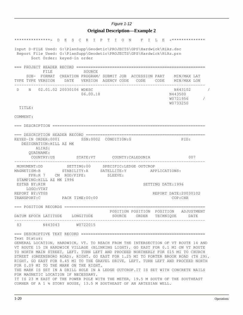
1-12 Original Description—Example 2 ...................................................................................................... 1-20
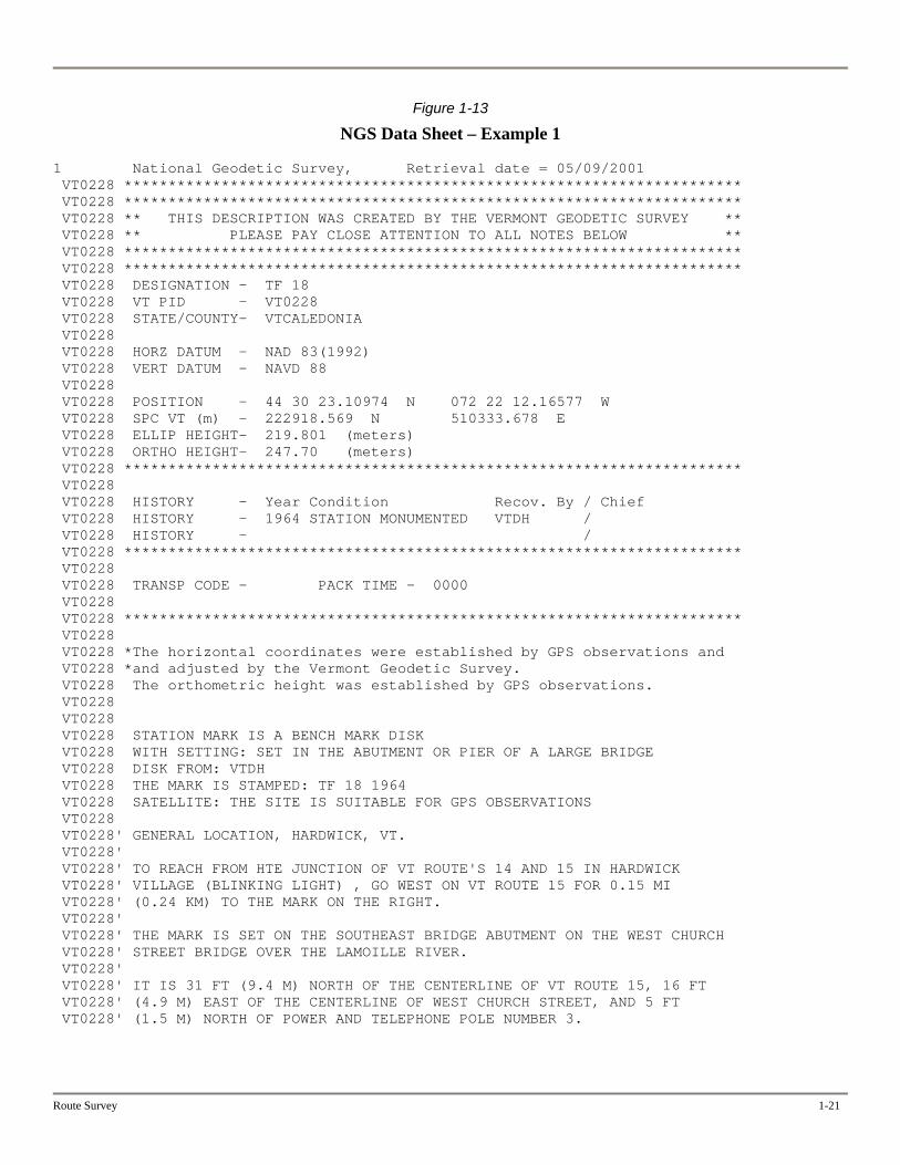
1-13 NGS Data Sheet—Example 1............................................................................................................. 1-21
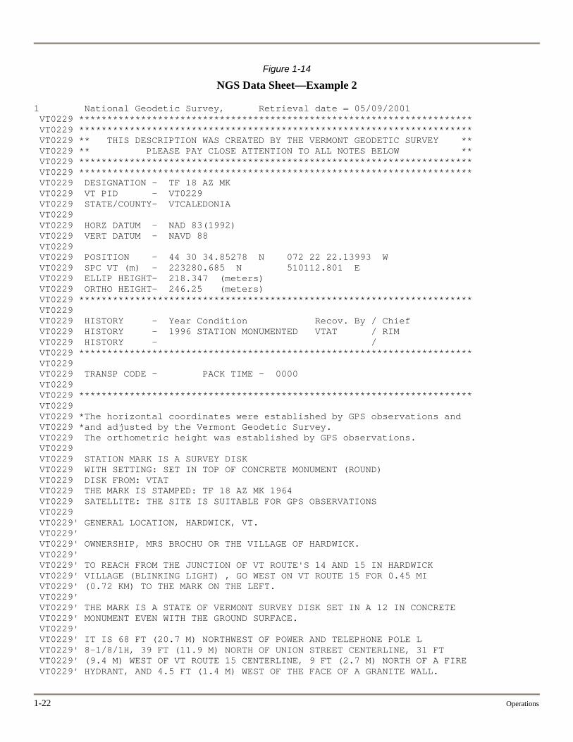
1-14 NGS Data Sheet—Example 2............................................................................................................. 1-22
1-15 Request for Right-of-Way Information .............................................................................................. 1-23
1-16 Reply to Request for Survey—Survey Estimate................................................................................. 1-24
1-17 Survey Transfer Memorandum........................................................................................................... 1-25
1-18 Survey Crew Report ........................................................................................................................... 1-26
2-1 Adjustment and Maintenance Checklist ............................................................................................... 2-2
2-2 Peg Test Setups..................................................................................................................................... 2-5
4-1 Point Numbering Ranges...................................................................................................................... 4-2
4-2 Accuracy Standards .............................................................................................................................. 4-3
4-3 Example Notes...................................................................................................................................... 4-4
5-1 Appropriate DTM Data Point Locations .............................................................................................. 5-3
5-2 Common Problems in DTM Data Point Locations............................................................................... 5-4
Route Survey ix
x List of Figures
5-3 Point Location—”Left” and “Right” .................................................................................................... 5-7
5-4 Point Location—Rural Area ................................................................................................................. 5-8
5-5 Point Location—Urban Area................................................................................................................ 5-9
5-6 Point Location—Drop Inlet ................................................................................................................ 5-10
5-7 Point Location—Retaining Wall ........................................................................................................ 5-11
5-8 Point Location—Bridge Deck ............................................................................................................ 5-12
5-9 Point Location—Bridge Abutment..................................................................................................... 5-13
5-9a Point Location—Bridge Abutment (Side View) ................................................................................ 5-14
5-10 Point Location—Pier and Abutment .................................................................................................. 5-15
5-11 Point Location—Large Pipe ............................................................................................................... 5-16
5-12 Point Location—Railroad................................................................................................................... 5-17
6-1 Positional Tolerances for Boundary Surveys........................................................................................ 6-1
6-2 Precision Ratios for Boundary Surveys................................................................................................ 6-1
6-3 Imaginary Surfaces at Civil Airports .................................................................................................... 6-4
A-1 Basic Trigonometric Formulas ............................................................................................................ A-2
A-2 Circular Curve Sketch.......................................................................................................................... A-3
A-3 Formulas and Procedure for Circular Curves in Metric Units............................................................. A-4
A-4 Formulas and Procedure for Circular Curves in English Units ........................................................... A-5
A-5 Spiral Curve Transition Sketch............................................................................................................ A-6
A-6 Formulas and Procedure for Spiral Curve Transitions in Metric Units ............................................... A-7
A-7 Formulas and Procedure for Spiral Curve Transitions in English Units ............................................. A-8
A-8 Parabolic Vertical Curve Sketch.......................................................................................................... A-9
A-9 Formulas and Procedure for Parabolic Vertical Curves in Metric or English Units.......................... A-10
A-10 Survey Units Conversion Table......................................................................................................... A-11
A-11 Feature Table ..................................................................................................................................... A-12
A-12 Feature Table Legend ........................................................................................................................ A-17
B-1 Vermont Coordinate System—Central Meridian and Lines of Exact Scale.........................................B-2
B-2 Table of Ellipsoid Corrections for Vermont Orthometric Height in Feet.............................................B-3
B-3 Transverse Mercator Projection for Vermont.......................................................................................B-4
B-4 Example Calculation 1..........................................................................................................................B-5

Route Survey xi
B-5 Example Calculation 2..........................................................................................................................B-7
B-6 Example Calculation 3..........................................................................................................................B-8
C-1 Specifications for AOT Boundary Markers—Reinforcing-Bar-and-Cap Type....................................C-2
C-2 Specifications for AOT Boundary Markers—Ledge Type ..................................................................C-3

VERMONT AGENCY OF TRANSPORTATION
Chapter One Operations
OVERVIEW
This manual covers route surveying work performed for the Agency and the management of data used by the Agency. It is written primarily for Agency party chiefs and supervisors. It also serves as a reference for setting the technical requirements of consultant contracts and as a reference for consultant party chiefs.
The manual focuses on equipment used by the Agency’s route survey crews, such as total stations and data collectors, but it includes other types of equipment, such as automatic levels. Because the manual is written for party chiefs and supervisors, rather than for crew members, the manual emphasizes standards and guidelines and excludes almost all elementary concepts, details of field methods, rationales for and details of calculations and adjustments, etc.
Typical Work
Survey requests for roadway design, structures, and construction account for nearly all of the work performed by the Route Survey Unit. Other work includes:
Railroad crossings and airport surveys
Retracement of right-of-way surveys for State highways
Property surveys for Agency land
Boundary surveys as requested by the Attorney General or Secretary of State, such as determining county or State lines and verifying the presence of monuments along boundaries
Representing the Agency on survey matters in courts of law
Processing 3D survey files for the requestor
Maintaining survey CADD files
Aerial photography is not used by the Route Survey Unit. If a consultant uses aerial photography, the Geodetic Survey Unit provides control
Route Survey 1-1
Metric Use
It is the intention of the Agency to use English Survey foot measurements unless there is an overriding reason to do otherwise.
INTERNAL ORGANIZATION AND RESPONSIBILITIES
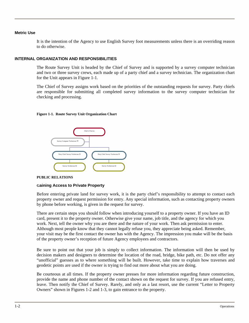
The Route Survey Unit is headed by the Chief of Survey and is supported by a survey computer technician and two or three survey crews, each made up of a party chief and a survey technician. The organization chart for the Unit appears in Figure 1-1.
The Chief of Survey assigns work based on the priorities of the outstanding requests for survey. Party chiefs are responsible for submitting all completed survey information to the survey computer technician for checking and processing.
Figure 1-1. Route Survey Unit Organization Chart
Chief of Survey
Party Chief Survey Technician IV
Party Chief Survey Technician IV
Survey Technician III Survey Technician III
Survey Computer Technician IV
PUBLIC RELATIONS
Gaining Access to Private Property
Before entering private land for survey work, it is the party chief’s responsibility to attempt to contact each property owner and request permission for entry. Any special information, such as contacting property owners by phone before working, is given in the request for survey.
There are certain steps you should follow when introducing yourself to a property owner. If you have an ID card, present it to the property owner. Otherwise give your name, job title, and the agency for which you work. Next, tell the owner why you are there and the nature of your work. Then ask permission to enter. Although most people know that they cannot legally refuse you, they appreciate being asked. Remember, your visit may be the first contact the owner has with the Agency. The impression you make will be the basis of the property owner’s reception of future Agency employees and contractors.
Be sure to point out that your job is simply to collect information. The information will then be used by decision makers and designers to determine the location of the road, bridge, bike path, etc. Do not offer any “unofficial” guesses as to where something will be built. However, take time to explain how traverses and geodetic points are used if the owner is trying to find out more about what you are doing.
Be courteous at all times. If the property owner presses for more information regarding future construction, provide the name and phone number of the contact shown on the request for survey. If you are refused entry, leave. Then notify the Chief of Survey. Rarely, and only as a last resort, use the current “Letter to Property Owners” shown in Figures 1-2 and 1-3, to gain entrance to the property.
1-2 Operations
Route Survey 1-3
On large projects, where many property owners will be affected, it’s a good idea to notify town officials of the upcoming survey work. Property owners may be more receptive to your presence when they expect to see you.
Dealings with the Media
Follow the same conduct with the media as with a property owner. Never speculate about the possible location of future construction.
Respect for Private Property
Always treat private property in the way you want others to treat your property. To that end, use roads if they are available. If off-road travel is necessary, avoid driving through wet areas to prevent ruts.
Cut and trim as few trees as possible. Stack cut brush neatly but not in an area where livestock graze—cut brush can cause injury or death to livestock if consumed. Also, be sure to close gates behind you to prevent livestock from escaping.
Avoid cutting, trimming, or harming ornamental or shade trees, hedges, and other plants near a residence. Report the extent of any damage caused by the survey crew, in writing, to the Chief of Survey.
To prevent damage to vehicle tires, countersink hubs and iron pins in and along roadways. Always check the area before leaving to be sure nothing is inadvertently left behind. Hubs, iron pins, nails, and the like can cause damage to vehicles and farm equipment and can cause injury or death to livestock.
Accessing Railroads and Airports
Always notify the appropriate railroad company or airport manager before arriving and when leaving. Make a list of the phone numbers of all railroad companies and airports and keep it up to date. Contact the appropriate Rail, Air, or Public Transportation unit for more information.

Figure 1-2
Letter to Property Owners—Front Side
STATE OF VERMONT Agency of Transportation
Program Development Division 1 National Life Drive, 4th Fl/
Montpelier VT 05633 Dear Property Owner: This will introduce who is employed by the Agency of Transportation, State of Vermont. The Agency of Transportation is conducting an engineering and/or property survey for a proposed public project and needs to have its surveying personnel enter upon your lands for that purpose, as permitted by statute. An extract of the pertinent statutes is shown on the attached sheet. Federal and State regulations require the Agency to obtain comment from property owners, local officials and other interested people before deciding upon the final details of a project. The survey is intended to give our personnel a complete picture of the area so they can determine with some accuracy what effects of the project will be. Please understand that the stakes as set out by Survey personnel may only be a reference line for surveying purposes. We appreciate your cooperation and assistance and hope that the results of the survey will be helpful to you and your neighbors when the time comes to decide on the project’s location and scope. If you desire additional information, please feel free to telephone me at (802) 828-_____ Sincerely, Director of Program Development
Attachment
Vermont is an Equal Opportunity Employer
1-4 Operations
Route Survey 1-5
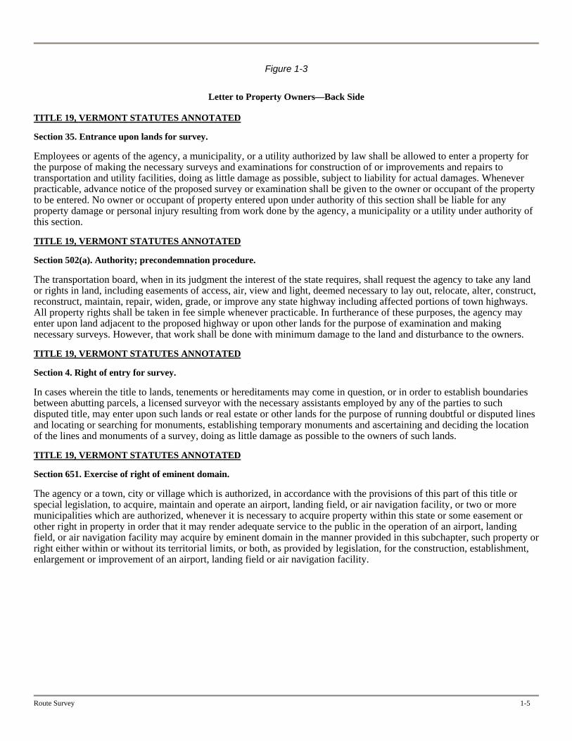
Figure 1-3
Letter to Property Owners—Back Side
TITLE 19, VERMONT STATUTES ANNOTATED Section 35. Entrance upon lands for survey. Employees or agents of the agency, a municipality, or a utility authorized by law shall be allowed to enter a property for the purpose of making the necessary surveys and examinations for construction of or improvements and repairs to transportation and utility facilities, doing as little damage as possible, subject to liability for actual damages. Whenever practicable, advance notice of the proposed survey or examination shall be given to the owner or occupant of the property to be entered. No owner or occupant of property entered upon under authority of this section shall be liable for any property damage or personal injury resulting from work done by the agency, a municipality or a utility under authority of this section. TITLE 19, VERMONT STATUTES ANNOTATED Section 502(a). Authority; precondemnation procedure. The transportation board, when in its judgment the interest of the state requires, shall request the agency to take any land or rights in land, including easements of access, air, view and light, deemed necessary to lay out, relocate, alter, construct, reconstruct, maintain, repair, widen, grade, or improve any state highway including affected portions of town highways. All property rights shall be taken in fee simple whenever practicable. In furtherance of these purposes, the agency may enter upon land adjacent to the proposed highway or upon other lands for the purpose of examination and making necessary surveys. However, that work shall be done with minimum damage to the land and disturbance to the owners. TITLE 19, VERMONT STATUTES ANNOTATED Section 4. Right of entry for survey. In cases wherein the title to lands, tenements or hereditaments may come in question, or in order to establish boundaries between abutting parcels, a licensed surveyor with the necessary assistants employed by any of the parties to such disputed title, may enter upon such lands or real estate or other lands for the purpose of running doubtful or disputed lines and locating or searching for monuments, establishing temporary monuments and ascertaining and deciding the location of the lines and monuments of a survey, doing as little damage as possible to the owners of such lands. TITLE 19, VERMONT STATUTES ANNOTATED Section 651. Exercise of right of eminent domain. The agency or a town, city or village which is authorized, in accordance with the provisions of this part of this title or special legislation, to acquire, maintain and operate an airport, landing field, or air navigation facility, or two or more municipalities which are authorized, whenever it is necessary to acquire property within this state or some easement or other right in property in order that it may render adequate service to the public in the operation of an airport, landing field, or air navigation facility may acquire by eminent domain in the manner provided in this subchapter, such property or right either within or without its territorial limits, or both, as provided by legislation, for the construction, establishment, enlargement or improvement of an airport, landing field or air navigation facility.
1-6 Operations
VEHICLE RULES AND REGULATIONS
Refer to Administrative Bulletin No. 2.3 for rules and regulations concerning the use of state-owned and privately owned vehicles. The Agency’s Policies and Procedures Manual and Safety Manual also contain important information regarding vehicle use.
The State may not be required to reimburse you for personal injury, property damage, and liability when you are involved in an accident while using a privately owned vehicle for State business.
SAFETY
All employees, and consultants working on State projects, should be familiar with the Safety Manual. In addition, there are a number of safety issues of particular interest to survey crews that are addressed here and referenced in other documents.
Working near the Traveled Way
When working near any roadway, wear a safety vest or VAOT-approved brightly colored clothing. When possible park the survey vehicle off the traveled way and use the vehicle’s strobe lights. If a lane closure is required, contact the district maintenance office for assistance.
Personal and Protective Equipment
Different job conditions require different personal protection, so plan ahead and use common sense. A few examples follow:
When working close to the traveled way, wear a safety vest and use signs in accordance with the Worksite Traffic Control Manual.
If you are allergic to poisonous plants, such as poison ivy, dress so that your skin is covered as much as possible.
In cold weather, wear multiple layers of clothing, with the outermost layer loose, so that your freedom of movement is not hindered.
Plan your work so that you are not in wooded areas during deer hunting season. If that’s not possible, wear brightly colored clothing.
If you are working on a construction project, dress appropriately as required by the resident engineer.
Always be sure that a fully stocked first aid kit is stowed in the survey vehicle.
Tools and Equipment
As a member of a survey crew, you should observe the following general rules:
Do not carry unguarded, sharp-edged or pointed tools in your pocket.
Store all tools in a well-designed compartment in the vehicle, separate from crew members.
Be sure that the area is clear of other people before swinging any tool.
Always use sharp tools to prevent rebounding.
Stay at least 10 feet from other people when cutting brush.
Always chop away from the body.
Clear small vegetation before clearing larger vegetation.
Be sure you have firm footing before swinging any tool.
Keep your eyes on the spot you are cutting or chopping.
Keep all sharp tools in a sheath when not in use.
Make sure the head of an axe or maul is tight on the handle before using it.
Avoid chopping frozen wood or knots.
When trimming limbs from a fallen tree trunk, stand to the side of the tree opposite the limb.
Hold the brush hook like you would an axe, except keep your upper hand a little more toward the cutting edge to give you better balance when making a low cut.
Strike at the base of plants when using a brush hook.
Carry a brush hook like you would an axe. Keep your hand close to the head. Always point the head to the front and never carry a brush hook on your shoulder.
Comply with all instructions on the labels of spray paint cans.
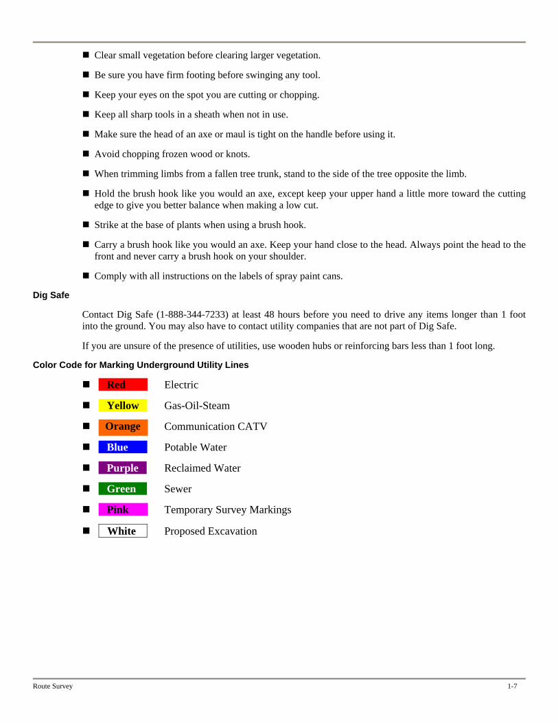
Dig Safe
Contact Dig Safe (1-888-344-7233) at least 48 hours before you need to drive any items longer than 1 foot into the ground. You may also have to contact utility companies that are not part of Dig Safe.
If you are unsure of the presence of utilities, use wooden hubs or reinforcing bars less than 1 foot long.
Color Code for Marking Underground Utility Lines
Red Electric
Yellow Gas-Oil-Steam
Communication CATV Orange
Blue Potable Water
Purple Reclaimed Water
Green Sewer
Pink Temporary Survey Markings
White Proposed Excavation
Route Survey 1-7
1-8 Operations
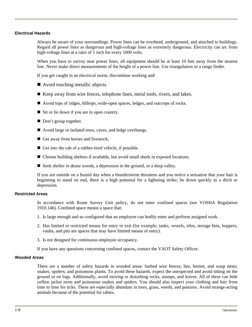
Electrical Hazards
Always be aware of your surroundings. Power lines can be overhead, underground, and attached to buildings. Regard all power lines as dangerous and high-voltage lines as extremely dangerous. Electricity can arc from high-voltage lines at a ratio of 1 inch for every 1000 volts.
When you have to survey near power lines, all equipment should be at least 10 feet away from the nearest line. Never make direct measurements of the height of a power line. Use triangulation or a range finder.
If you get caught in an electrical storm, discontinue working and:
Avoid touching metallic objects.
Keep away from wire fences, telephone lines, metal tools, rivers, and lakes.
Avoid tops of ridges, hilltops, wide-open spaces, ledges, and outcrops of rocks.
Sit or lie down if you are in open country.
Don’t group together.
Avoid large or isolated trees, caves, and ledge overhangs.
Get away from horses and livestock.
Get into the cab of a rubber-tired vehicle, if possible.
Choose building shelters if available, but avoid small sheds in exposed locations.
Seek shelter in dense woods, a depression in the ground, or a deep valley.
If you are outside on a humid day when a thunderstorm threatens and you notice a sensation that your hair is beginning to stand on end, there is a high potential for a lightning strike; lie down quickly in a ditch or depression.
Restricted Areas
In accordance with Route Survey Unit policy, do not enter confined spaces (see VOSHA Regulation 1910.146). Confined space means a space that:
1. Is large enough and so configured that an employee can bodily enter and perform assigned work.
2. Has limited or restricted means for entry or exit (for example, tanks, vessels, silos, storage bins, hoppers, vaults, and pits are spaces that may have limited means of entry).
3. Is not designed for continuous employee occupancy.
If you have any questions concerning confined spaces, contact the VAOT Safety Officer.
Wooded Areas
There are a number of safety hazards in wooded areas: barbed wire fences; bee, hornet, and wasp nests; snakes; spiders; and poisonous plants. To avoid these hazards, expect the unexpected and avoid sitting on the ground or on logs. Additionally, avoid moving or disturbing rocks, stumps, and leaves. All of these can hide yellow jacket nests and poisonous snakes and spiders. You should also inspect your clothing and hair from time to time for ticks. These are especially abundant in trees, grass, weeds, and pastures. Avoid strange-acting animals because of the potential for rabies.
Route Survey 1-9
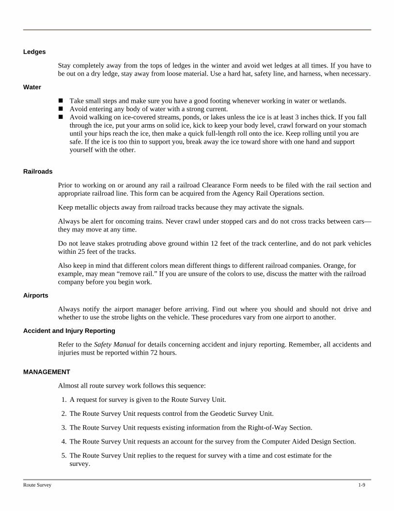
Ledges
Stay completely away from the tops of ledges in the winter and avoid wet ledges at all times. If you have to be out on a dry ledge, stay away from loose material. Use a hard hat, safety line, and harness, when necessary.
Water
Take small steps and make sure you have a good footing whenever working in water or wetlands. Avoid entering any body of water with a strong current. Avoid walking on ice-covered streams, ponds, or lakes unless the ice is at least 3 inches thick. If you fall
through the ice, put your arms on solid ice, kick to keep your body level, crawl forward on your stomach until your hips reach the ice, then make a quick full-length roll onto the ice. Keep rolling until you are safe. If the ice is too thin to support you, break away the ice toward shore with one hand and support yourself with the other.
Railroads
Prior to working on or around any rail a railroad Clearance Form needs to be filed with the rail section and appropriate railroad line. This form can be acquired from the Agency Rail Operations section.
Keep metallic objects away from railroad tracks because they may activate the signals.
Always be alert for oncoming trains. Never crawl under stopped cars and do not cross tracks between cars—they may move at any time.
Do not leave stakes protruding above ground within 12 feet of the track centerline, and do not park vehicles within 25 feet of the tracks.
Also keep in mind that different colors mean different things to different railroad companies. Orange, for example, may mean “remove rail.” If you are unsure of the colors to use, discuss the matter with the railroad company before you begin work.
Airports
Always notify the airport manager before arriving. Find out where you should and should not drive and whether to use the strobe lights on the vehicle. These procedures vary from one airport to another.
Accident and Injury Reporting
Refer to the Safety Manual for details concerning accident and injury reporting. Remember, all accidents and injuries must be reported within 72 hours.
MANAGEMENT
Almost all route survey work follows this sequence:
1. A request for survey is given to the Route Survey Unit.
2. The Route Survey Unit requests control from the Geodetic Survey Unit.
3. The Route Survey Unit requests existing information from the Right-of-Way Section.
4. The Route Survey Unit requests an account for the survey from the Computer Aided Design Section.
5. The Route Survey Unit replies to the request for survey with a time and cost estimate for the survey.
1-10 Operations
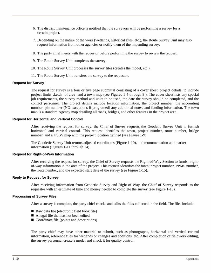
6. The district maintenance office is notified that the surveyors will be performing a survey for a certain project.
7. Depending on the nature of the work (wetlands, historical sites, etc.), the Route Survey Unit may also request information from other agencies or notify them of the impending survey.
8. The party chief meets with the requestor before performing the survey to review the request.
9. The Route Survey Unit completes the survey.
10. The Route Survey Unit processes the survey files (creates the model, etc.).
11. The Route Survey Unit transfers the survey to the requestor.
Request for Survey
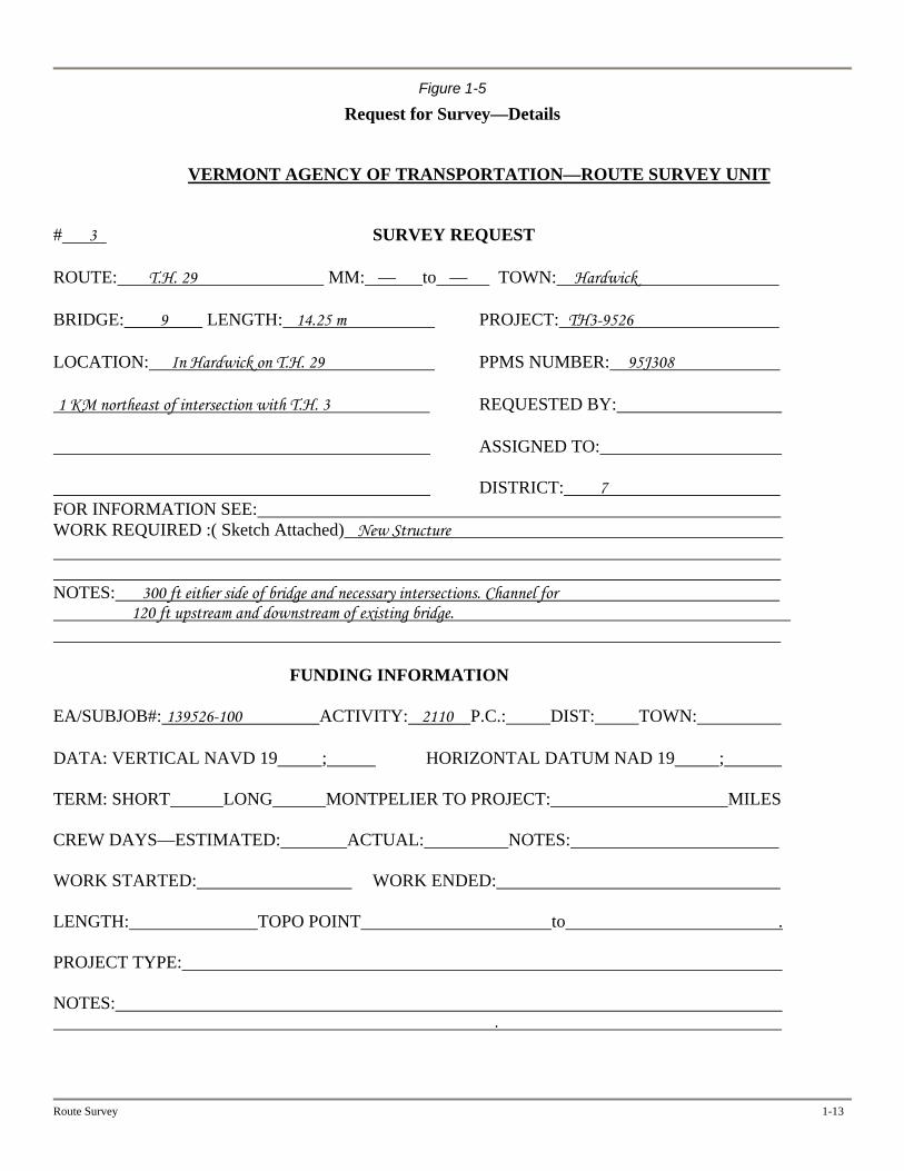
The request for survey is a four or five page submittal consisting of a cover sheet, project details, to include project limits sketch of area and a town map (see Figures 1-4 through 8 ). The cover sheet lists any special job requirements, the survey method and units to be used, the date the survey should be completed, and the contact personnel. The project details include location information, the project number, the accounting number, pin number (NO exceptions if programed) any additional notes, and funding information. The town map is a standard Agency map detailing all roads, bridges, and other features in the project area.
Request for Horizontal and Vertical Control
After receiving the request for survey, the Chief of Survey requests the Geodetic Survey Unit to furnish horizontal and vertical control. This request identifies the town, project number, route number, bridge number, and a USGS map with the project location defined (see Figure 1-9).
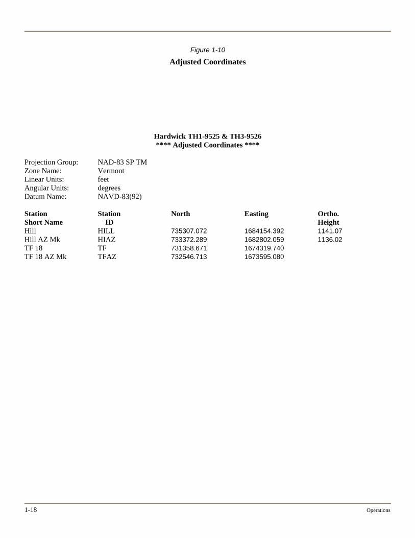
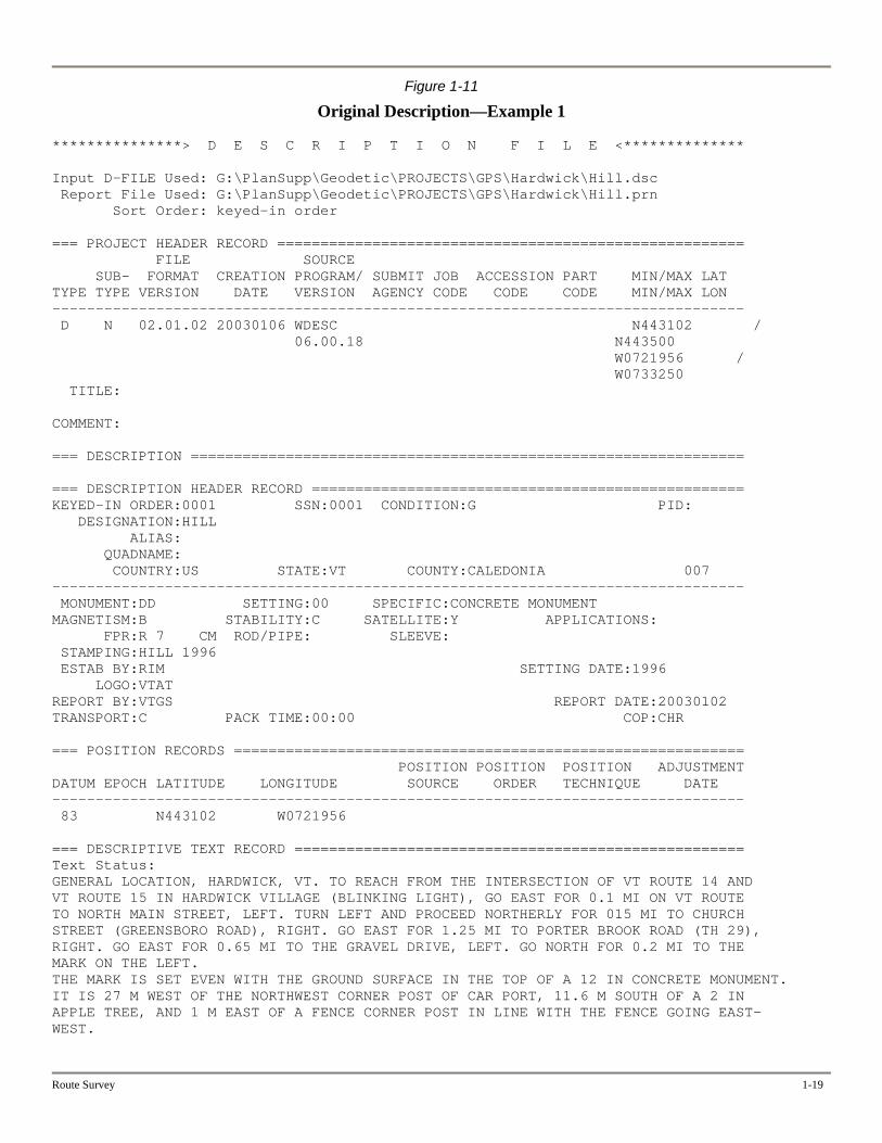
The Geodetic Survey Unit returns adjusted coordinates (Figure 1-10), and monumentation and marker information (Figures 1-11 through 14).
Request for Right-of-Way Information
After receiving the request for survey, the Chief of Survey requests the Right-of-Way Section to furnish right-of-way information in the area of the project. This request identifies the town; project number, PPMS number, the route number, and the expected start date of the survey (see Figure 1-15).
Reply to Request for Survey
After receiving information from Geodetic Survey and Right-of-Way, the Chief of Survey responds to the requestor with an estimate of time and money needed to complete the survey (see Figure 1-16).
Processing of Survey Files
After a survey is complete, the party chief checks and edits the files collected in the field. The files include:
Raw data file (electronic field book file) A legal file that has not been edited Coordinate file (points and descriptions)
The party chief may have other material to submit, such as photographs, horizontal and vertical control information, reference files for wetlands or changes and additions, etc. After completion of fieldwork editing, the survey personnel create a model and check it for quality control.
Route Survey 1-11
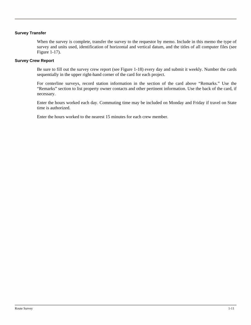
Survey Transfer
When the survey is complete, transfer the survey to the requestor by memo. Include in this memo the type of survey and units used, identification of horizontal and vertical datum, and the titles of all computer files (see Figure 1-17).
Survey Crew Report
Be sure to fill out the survey crew report (see Figure 1-18) every day and submit it weekly. Number the cards sequentially in the upper right-hand corner of the card for each project.
For centerline surveys, record station information in the section of the card above “Remarks.” Use the “Remarks” section to list property owner contacts and other pertinent information. Use the back of the card, if necessary.
Enter the hours worked each day. Commuting time may be included on Monday and Friday if travel on State time is authorized.
Enter the hours worked to the nearest 15 minutes for each crew member.
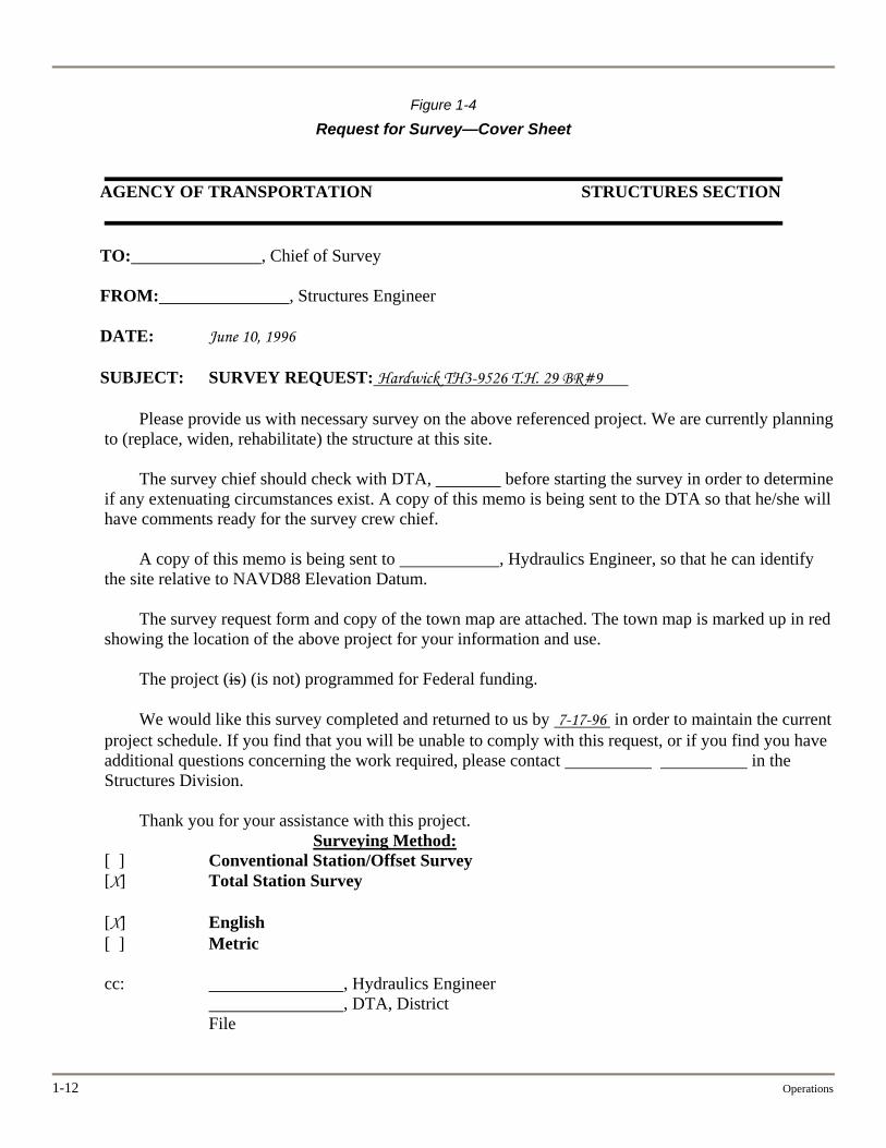
Figure 1-4
Request for Survey—Cover Sheet
AGENCY OF TRANSPORTATION STRUCTURES SECTION TO: , Chief of Survey FROM: , Structures Engineer DATE: June 10, 1996 SUBJECT: SURVEY REQUEST: Hardwick TH3-9526 T.H. 29 BR#9
Please provide us with necessary survey on the above referenced project. We are currently planning to (replace, widen, rehabilitate) the structure at this site.
The survey chief should check with DTA, before starting the survey in order to determine if any extenuating circumstances exist. A copy of this memo is being sent to the DTA so that he/she will have comments ready for the survey crew chief.
A copy of this memo is being sent to , Hydraulics Engineer, so that he can identify the site relative to NAVD88 Elevation Datum.
The survey request form and copy of the town map are attached. The town map is marked up in red showing the location of the above project for your information and use.
The project (is) (is not) programmed for Federal funding.
We would like this survey completed and returned to us by 7-17-96 in order to maintain the current project schedule. If you find that you will be unable to comply with this request, or if you find you have additional questions concerning the work required, please contact in the Structures Division.
Thank you for your assistance with this project.
Surveying Method: [ ] Conventional Station/Offset Survey [X] Total Station Survey [X] English [ ] Metric cc: , Hydraulics Engineer
, DTA, District File
1-12 Operations
Route Survey 1-13
Figure 1-5
Request for Survey—Details
VERMONT AGENCY OF TRANSPORTATION—ROUTE SURVEY UNIT
# 3 SURVEY REQUEST ROUTE: T.H. 29 MM: — to — TOWN: Hardwick BRIDGE: 9 LENGTH: 14.25 m PROJECT: TH3-9526 LOCATION: In Hardwick on T.H. 29 PPMS NUMBER: 95J308 1 KM northeast of intersection with T.H. 3 REQUESTED BY: ASSIGNED TO: DISTRICT: 7 FOR INFORMATION SEE: WORK REQUIRED :( Sketch Attached) New Structure NOTES: 300 ft either side of bridge and necessary intersections. Channel for 120 ft upstream and downstream of existing bridge. FUNDING INFORMATION EA/SUBJOB#: 139526-100 ACTIVITY: 2110 P.C.: DIST: TOWN: DATA: VERTICAL NAVD 19 ; HORIZONTAL DATUM NAD 19 ; TERM: SHORT LONG MONTPELIER TO PROJECT: MILES CREW DAYS—ESTIMATED: ACTUAL: NOTES: WORK STARTED: WORK ENDED: LENGTH: TOPO POINT to . PROJECT TYPE: NOTES: .
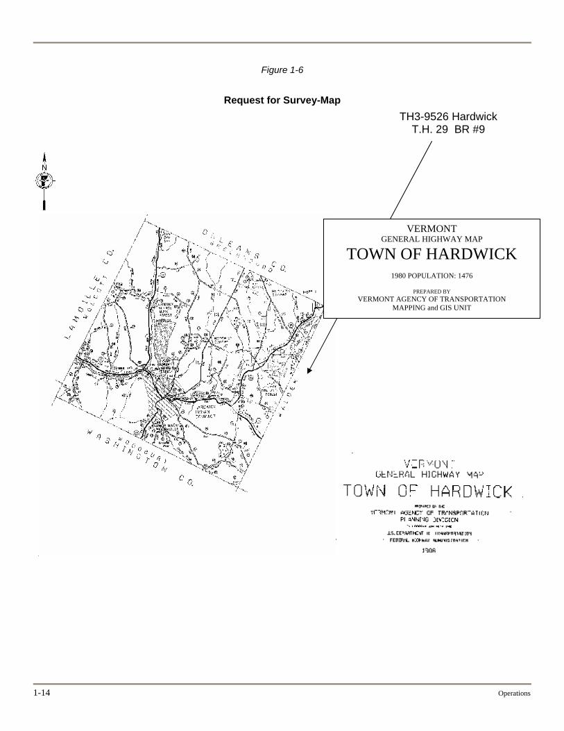
Figure 1-6
Request for Survey-Map TH3-9526 Hardwick
T.H. 29 BR #9
1-14 Operations
VERMONT GENERAL HIGHWAY MAP
TOWN OF HARDWICK
1980 POPULATION: 1476
PREPARED BY VERMONT AGENCY OF TRANSPORTATION
MAPPING and GIS UNIT
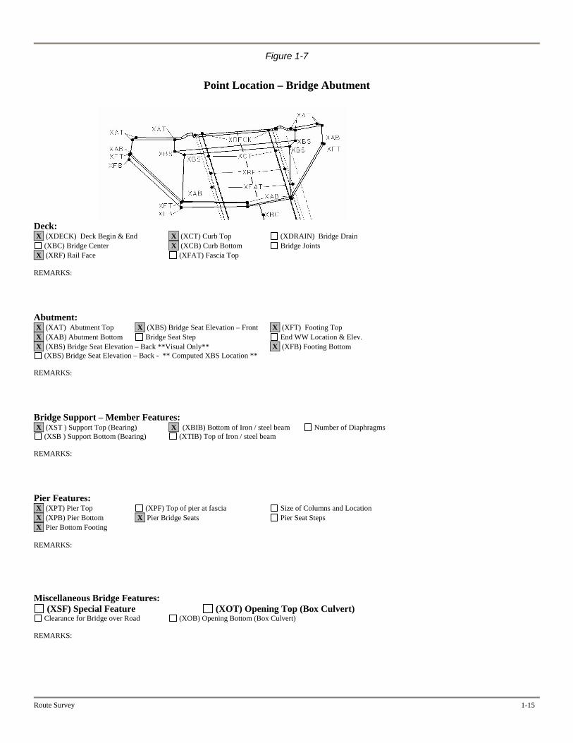
Figure 1-7
Point Location – Bridge Abutment
Deck: X (XDECK) Deck Begin & End X (XCT) Curb Top (XDRAIN) Bridge Drain
(XBC) Bridge Center X (XCB) Curb Bottom Bridge Joints X (XRF) Rail Face (XFAT) Fascia Top REMARKS: Abutment: X (XAT) Abutment Top X (XBS) Bridge Seat Elevation – Front X (XFT) Footing Top X (XAB) Abutment Bottom Bridge Seat Step End WW Location & Elev. X (XBS) Bridge Seat Elevation – Back **Visual Only** X (XFB) Footing Bottom
(XBS) Bridge Seat Elevation – Back - ** Computed XBS Location ** REMARKS: Bridge Support – Member Features: X (XST ) Support Top (Bearing) X (XBIB) Bottom of Iron / steel beam Number of Diaphragms
(XSB ) Support Bottom (Bearing) (XTIB) Top of Iron / steel beam REMARKS: Pier Features: X (XPT) Pier Top (XPF) Top of pier at fascia Size of Columns and Location X (XPB) Pier Bottom X Pier Bridge Seats Pier Seat Steps X Pier Bottom Footing REMARKS: Miscellaneous Bridge Features:
(XSF) Special Feature (XOT) Opening Top (Box Culvert) Clearance for Bridge over Road (XOB) Opening Bottom (Box Culvert)
REMARKS:
Route Survey 1-15
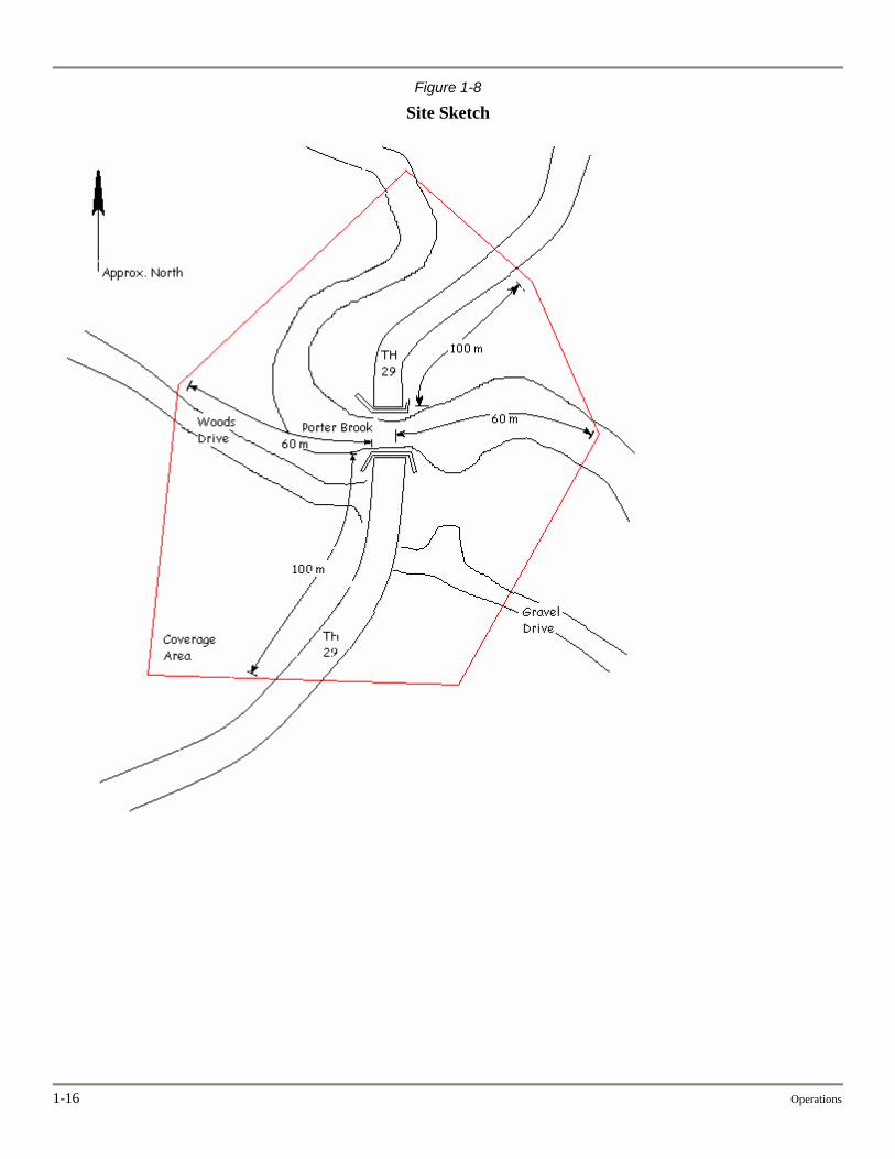
Figure 1-8
Site Sketch
1-16 Operations
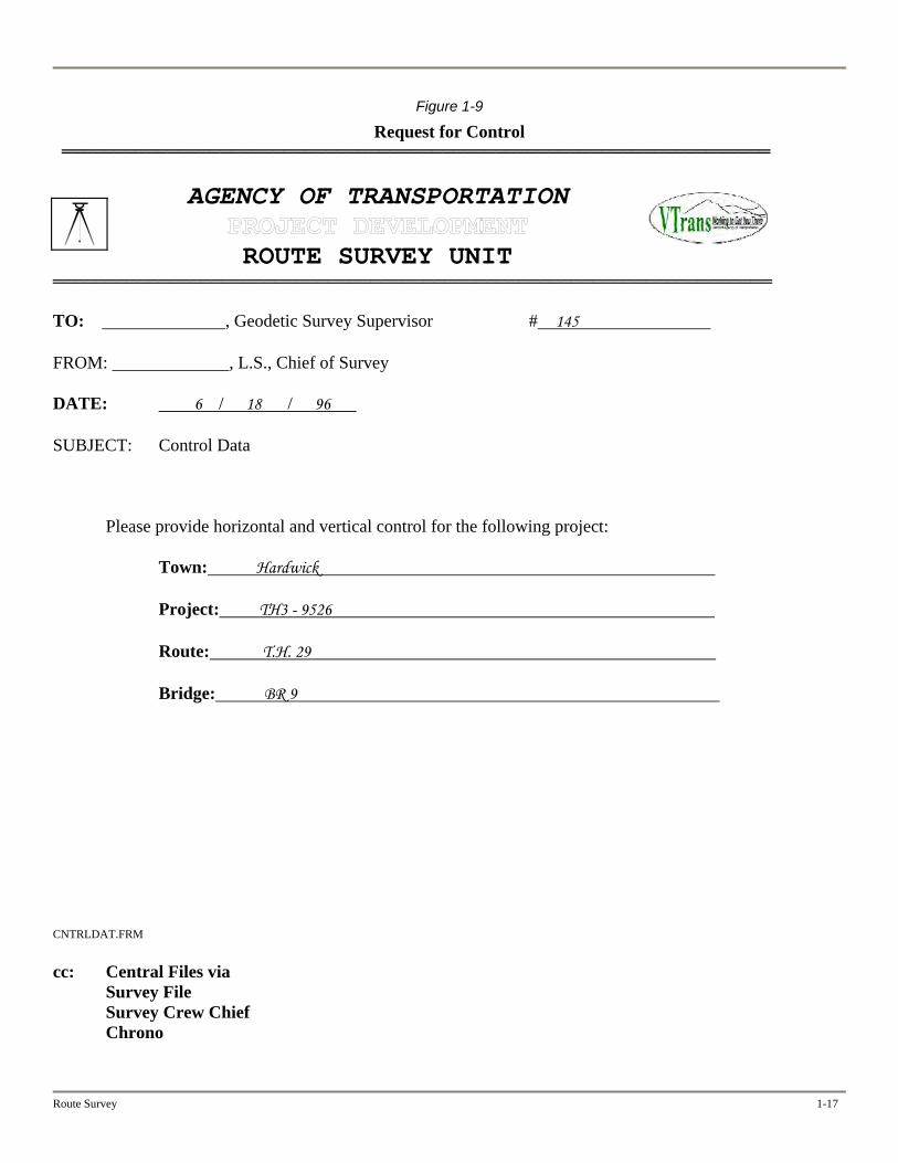
Figure 1-9
Request for Control ═══════════════════════════════════════════════════════════════════
AGENCY OF TRANSPORTATION
ROUTE SURVEY UNIT ════════════════════════════════════════════════════════════════════ TO: , Geodetic Survey Supervisor # 145 FROM: , L.S., Chief of Survey DATE: 6 / 18 / 96 SUBJECT: Control Data
Please provide horizontal and vertical control for the following project:
Town: Hardwick Project: TH3 - 9526
Route: T.H. 29
Bridge: BR 9
CNTRLDAT.FRM cc: Central Files via
Survey File Survey Crew Chief Chrono
Route Survey 1-17
1-18 Operations
Figure 1-10
Adjusted Coordinates
Hardwick TH1-9525 & TH3-9526 **** Adjusted Coordinates ****
Projection Group: NAD-83 SP TM Zone Name: Vermont Linear Units: feet Angular Units: degrees Datum Name: NAVD-83(92) Station Station North Easting Ortho. Short Name ID Height Hill HILL 735307.072 1684154.392 1141.07 Hill AZ Mk HIAZ 733372.289 1682802.059 1136.02 TF 18 TF 731358.671 1674319.740 TF 18 AZ Mk TFAZ 732546.713 1673595.080
Route Survey 1-19
Figure 1-11
Original Description—Example 1 ***************> D E S C R I P T I O N F I L E <************** Input D-FILE Used: G:\PlanSupp\Geodetic\PROJECTS\GPS\Hardwick\Hill.dsc Report File Used: G:\PlanSupp\Geodetic\PROJECTS\GPS\Hardwick\Hill.prn Sort Order: keyed-in order === PROJECT HEADER RECORD ====================================================== FILE SOURCE SUB- FORMAT CREATION PROGRAM/ SUBMIT JOB ACCESSION PART MIN/MAX LAT TYPE TYPE VERSION DATE VERSION AGENCY CODE CODE CODE MIN/MAX LON -------------------------------------------------------------------------------- D N 02.01.02 20030106 WDESC N443102 / 06.00.18 N443500 W0721956 / W0733250 TITLE: COMMENT: === DESCRIPTION ================================================================ === DESCRIPTION HEADER RECORD ================================================== KEYED-IN ORDER:0001 SSN:0001 CONDITION:G PID: DESIGNATION:HILL ALIAS: QUADNAME: COUNTRY:US STATE:VT COUNTY:CALEDONIA 007 -------------------------------------------------------------------------------- MONUMENT:DD SETTING:00 SPECIFIC:CONCRETE MONUMENT MAGNETISM:B STABILITY:C SATELLITE:Y APPLICATIONS: FPR:R 7 CM ROD/PIPE: SLEEVE: STAMPING:HILL 1996 ESTAB BY:RIM SETTING DATE:1996 LOGO:VTAT REPORT BY:VTGS REPORT DATE:20030102 TRANSPORT:C PACK TIME:00:00 COP:CHR === POSITION RECORDS =========================================================== POSITION POSITION POSITION ADJUSTMENT DATUM EPOCH LATITUDE LONGITUDE SOURCE ORDER TECHNIQUE DATE -------------------------------------------------------------------------------- 83 N443102 W0721956 === DESCRIPTIVE TEXT RECORD ==================================================== Text Status: GENERAL LOCATION, HARDWICK, VT. TO REACH FROM THE INTERSECTION OF VT ROUTE 14 AND VT ROUTE 15 IN HARDWICK VILLAGE (BLINKING LIGHT), GO EAST FOR 0.1 MI ON VT ROUTE TO NORTH MAIN STREET, LEFT. TURN LEFT AND PROCEED NORTHERLY FOR 015 MI TO CHURCH STREET (GREENSBORO ROAD), RIGHT. GO EAST FOR 1.25 MI TO PORTER BROOK ROAD (TH 29), RIGHT. GO EAST FOR 0.65 MI TO THE GRAVEL DRIVE, LEFT. GO NORTH FOR 0.2 MI TO THE MARK ON THE LEFT. THE MARK IS SET EVEN WITH THE GROUND SURFACE IN THE TOP OF A 12 IN CONCRETE MONUMENT. IT IS 27 M WEST OF THE NORTHWEST CORNER POST OF CAR PORT, 11.6 M SOUTH OF A 2 IN APPLE TREE, AND 1 M EAST OF A FENCE CORNER POST IN LINE WITH THE FENCE GOING EAST- WEST.
1-20 Operations
Figure 1-12
Original Description—Example 2 ***************> D E S C R I P T I O N F I L E <************** Input D-FILE Used: G:\PlanSupp\Geodetic\PROJECTS\GPS\Hardwick\HiAz.dsc Report File Used: G:\PlanSupp\Geodetic\PROJECTS\GPS\Hardwick\HiAz.prn Sort Order: keyed-in order === PROJECT HEADER RECORD ====================================================== FILE SOURCE SUB- FORMAT CREATION PROGRAM/ SUBMIT JOB ACCESSION PART MIN/MAX LAT TYPE TYPE VERSION DATE VERSION AGENCY CODE CODE CODE MIN/MAX LON -------------------------------------------------------------------------------- D N 02.01.02 20030106 WDESC N443102 / 06.00.18 N443500 W0721956 / W0733250 TITLE: COMMENT: === DESCRIPTION ================================================================ === DESCRIPTION HEADER RECORD ================================================== KEYED-IN ORDER:0001 SSN:0002 CONDITION:G PID: DESIGNATION:HILL AZ MK ALIAS: QUADNAME: COUNTRY:US STATE:VT COUNTY:CALEDONIA 007 -------------------------------------------------------------------------------- MONUMENT:DD SETTING:00 SPECIFIC:LEDGE OUTCROP MAGNETISM:B STABILITY:A SATELLITE:Y APPLICATIONS: FPR:R 7 CM ROD/PIPE: SLEEVE: STAMPING:HILL AZ MK 1996 ESTAB BY:RIM SETTING DATE:1996 LOGO:VTAT REPORT BY:VTGS REPORT DATE:20030102 TRANSPORT:C PACK TIME:00:00 COP:CHR === POSITION RECORDS =========================================================== POSITION POSITION POSITION ADJUSTMENT DATUM EPOCH LATITUDE LONGITUDE SOURCE ORDER TECHNIQUE DATE -------------------------------------------------------------------------------- 83 N443043 W0722015 === DESCRIPTIVE TEXT RECORD ==================================================== Text Status: GENERAL LOCATION, HARDWICK, VT. TO REACH FROM THE INTERSECTION OF VT ROUTE 14 AND VT ROUTE 15 IN HARDWICK VILLAGE (BLINKING LIGHT), GO EAST FOR 0.1 MI ON VT ROUTE TO NORTH MAIN STREET, LEFT. TURN LEFT AND PROCEED NORTHERLY FOR 015 MI TO CHURCH STREET (GREENSBORO ROAD), RIGHT. GO EAST FOR 1.25 MI TO PORTER BROOK ROAD (TH 29), RIGHT. GO EAST FOR 0.45 MI TO THE GRAVEL DRIVE, LEFT. TURN LEFT AND PROCEED NORTH FOR 0.09 MI TO THE MARK ON THE RIGHT. THE MARK IS SET IN A DRILL HOLE IN A LEDGE OUTCROP.IT IS SET WITH CONCRETE NAILS FOR MAGNETIC LOCATION IF NECESSARY. IT IS 23 M EAST OF THE POWER POLE WITH THE METER, 19.5 M SOUTH OF THE SOUTHEAST CORNER OF A 1 ½ STORY HOUSE, 13.5 M SOUTHEAST OF AN ARTESIAN WELL.
Route Survey 1-21
Figure 1-13
NGS Data Sheet – Example 1 1 National Geodetic Survey, Retrieval date = 05/09/2001 VT0228 ********************************************************************** VT0228 ********************************************************************** VT0228 ** THIS DESCRIPTION WAS CREATED BY THE VERMONT GEODETIC SURVEY ** VT0228 ** PLEASE PAY CLOSE ATTENTION TO ALL NOTES BELOW ** VT0228 ********************************************************************** VT0228 ********************************************************************** VT0228 DESIGNATION - TF 18 VT0228 VT PID - VT0228 VT0228 STATE/COUNTY- VTCALEDONIA VT0228 VT0228 HORZ DATUM - NAD 83(1992) VT0228 VERT DATUM - NAVD 88 VT0228 VT0228 POSITION - 44 30 23.10974 N 072 22 12.16577 W VT0228 SPC VT (m) - 222918.569 N 510333.678 E VT0228 ELLIP HEIGHT- 219.801 (meters) VT0228 ORTHO HEIGHT- 247.70 (meters) VT0228 ********************************************************************** VT0228 VT0228 HISTORY - Year Condition Recov. By / Chief VT0228 HISTORY - 1964 STATION MONUMENTED VTDH / VT0228 HISTORY - / VT0228 ********************************************************************** VT0228 VT0228 TRANSP CODE - PACK TIME - 0000 VT0228 VT0228 ********************************************************************** VT0228 VT0228 *The horizontal coordinates were established by GPS observations and VT0228 *and adjusted by the Vermont Geodetic Survey. VT0228 The orthometric height was established by GPS observations. VT0228 VT0228 VT0228 STATION MARK IS A BENCH MARK DISK VT0228 WITH SETTING: SET IN THE ABUTMENT OR PIER OF A LARGE BRIDGE VT0228 DISK FROM: VTDH VT0228 THE MARK IS STAMPED: TF 18 1964 VT0228 SATELLITE: THE SITE IS SUITABLE FOR GPS OBSERVATIONS VT0228 VT0228' GENERAL LOCATION, HARDWICK, VT. VT0228' VT0228' TO REACH FROM HTE JUNCTION OF VT ROUTE'S 14 AND 15 IN HARDWICK VT0228' VILLAGE (BLINKING LIGHT) , GO WEST ON VT ROUTE 15 FOR 0.15 MI VT0228' (0.24 KM) TO THE MARK ON THE RIGHT. VT0228' VT0228' THE MARK IS SET ON THE SOUTHEAST BRIDGE ABUTMENT ON THE WEST CHURCH VT0228' STREET BRIDGE OVER THE LAMOILLE RIVER. VT0228' VT0228' IT IS 31 FT (9.4 M) NORTH OF THE CENTERLINE OF VT ROUTE 15, 16 FT VT0228' (4.9 M) EAST OF THE CENTERLINE OF WEST CHURCH STREET, AND 5 FT VT0228' (1.5 M) NORTH OF POWER AND TELEPHONE POLE NUMBER 3.
1-22 Operations
Figure 1-14
NGS Data Sheet—Example 2 1 National Geodetic Survey, Retrieval date = 05/09/2001 VT0229 ********************************************************************** VT0229 ********************************************************************** VT0229 ** THIS DESCRIPTION WAS CREATED BY THE VERMONT GEODETIC SURVEY ** VT0229 ** PLEASE PAY CLOSE ATTENTION TO ALL NOTES BELOW ** VT0229 ********************************************************************** VT0229 ********************************************************************** VT0229 DESIGNATION - TF 18 AZ MK VT0229 VT PID - VT0229 VT0229 STATE/COUNTY- VTCALEDONIA VT0229 VT0229 HORZ DATUM - NAD 83(1992) VT0229 VERT DATUM - NAVD 88 VT0229 VT0229 POSITION - 44 30 34.85278 N 072 22 22.13993 W VT0229 SPC VT (m) - 223280.685 N 510112.801 E VT0229 ELLIP HEIGHT- 218.347 (meters) VT0229 ORTHO HEIGHT- 246.25 (meters) VT0229 ********************************************************************** VT0229 VT0229 HISTORY - Year Condition Recov. By / Chief VT0229 HISTORY - 1996 STATION MONUMENTED VTAT / RIM VT0229 HISTORY - / VT0229 ********************************************************************** VT0229 VT0229 TRANSP CODE - PACK TIME - 0000 VT0229 VT0229 ********************************************************************** VT0229 VT0229 *The horizontal coordinates were established by GPS observations and VT0229 *and adjusted by the Vermont Geodetic Survey. VT0229 The orthometric height was established by GPS observations. VT0229 VT0229 STATION MARK IS A SURVEY DISK VT0229 WITH SETTING: SET IN TOP OF CONCRETE MONUMENT (ROUND) VT0229 DISK FROM: VTAT VT0229 THE MARK IS STAMPED: TF 18 AZ MK 1964 VT0229 SATELLITE: THE SITE IS SUITABLE FOR GPS OBSERVATIONS VT0229 VT0229' GENERAL LOCATION, HARDWICK, VT. VT0229' VT0229' OWNERSHIP, MRS BROCHU OR THE VILLAGE OF HARDWICK. VT0229' VT0229' TO REACH FROM THE JUNCTION OF VT ROUTE'S 14 AND 15 IN HARDWICK VT0229' VILLAGE (BLINKING LIGHT) , GO WEST ON VT ROUTE 15 FOR 0.45 MI VT0229' (0.72 KM) TO THE MARK ON THE LEFT. VT0229' VT0229' THE MARK IS A STATE OF VERMONT SURVEY DISK SET IN A 12 IN CONCRETE VT0229' MONUMENT EVEN WITH THE GROUND SURFACE. VT0229' VT0229' IT IS 68 FT (20.7 M) NORTHWEST OF POWER AND TELEPHONE POLE L VT0229' 8-1/8/1H, 39 FT (11.9 M) NORTH OF UNION STREET CENTERLINE, 31 FT VT0229' (9.4 M) WEST OF VT ROUTE 15 CENTERLINE, 9 FT (2.7 M) NORTH OF A FIRE VT0229' HYDRANT, AND 4.5 FT (1.4 M) WEST OF THE FACE OF A GRANITE WALL.
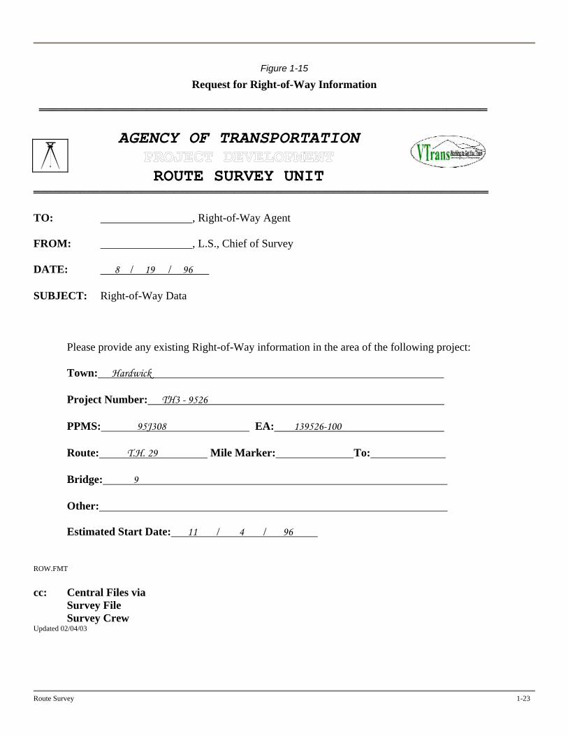
Figure 1-15
Request for Right-of-Way Information ═══════════════════════════════════════════════════════════════════
AGENCY OF TRANSPORTATION
ROUTE SURVEY UNIT ════════════════════════════════════════════════════════════════════ TO: , Right-of-Way Agent FROM: , L.S., Chief of Survey DATE: 8 / 19 / 96 SUBJECT: Right-of-Way Data
Please provide any existing Right-of-Way information in the area of the following project:
Town: Hardwick
Project Number: TH3 - 9526 PPMS: 95J308 EA: 139526-100
Route: T.H. 29 Mile Marker: To:
Bridge: 9
Other:
Estimated Start Date: 11 / 4 / 96
ROW.FMT cc: Central Files via
Survey File Survey Crew
Updated 02/04/03
Route Survey 1-23
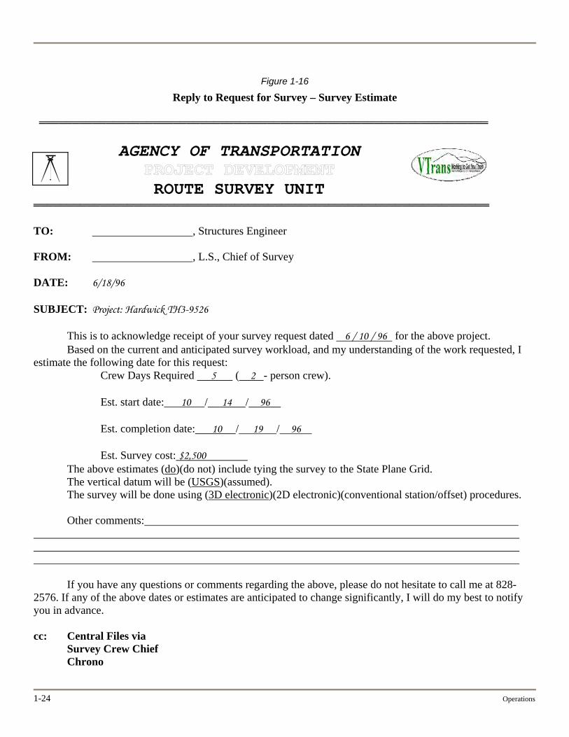
Figure 1-16
Reply to Request for Survey – Survey Estimate ═══════════════════════════════════════════════════════════════════
AGENCY OF TRANSPORTATION
ROUTE SURVEY UNIT ════════════════════════════════════════════════════════════════════ TO: , Structures Engineer FROM: , L.S., Chief of Survey DATE: 6/18/96 SUBJECT: Project: Hardwick TH3-9526
This is to acknowledge receipt of your survey request dated 6 / 10 / 96 for the above project. Based on the current and anticipated survey workload, and my understanding of the work requested, I
estimate the following date for this request: Crew Days Required 5 ( 2 - person crew). Est. start date: 10 / 14 / 96
Est. completion date: 10 / 19 / 96
Est. Survey cost: $2,500
The above estimates (do)(do not) include tying the survey to the State Plane Grid. The vertical datum will be (USGS)(assumed). The survey will be done using (3D electronic)(2D electronic)(conventional station/offset) procedures.
Other comments:
If you have any questions or comments regarding the above, please do not hesitate to call me at 828-2576. If any of the above dates or estimates are anticipated to change significantly, I will do my best to notify you in advance. cc: Central Files via
Survey Crew Chief Chrono
1-24 Operations
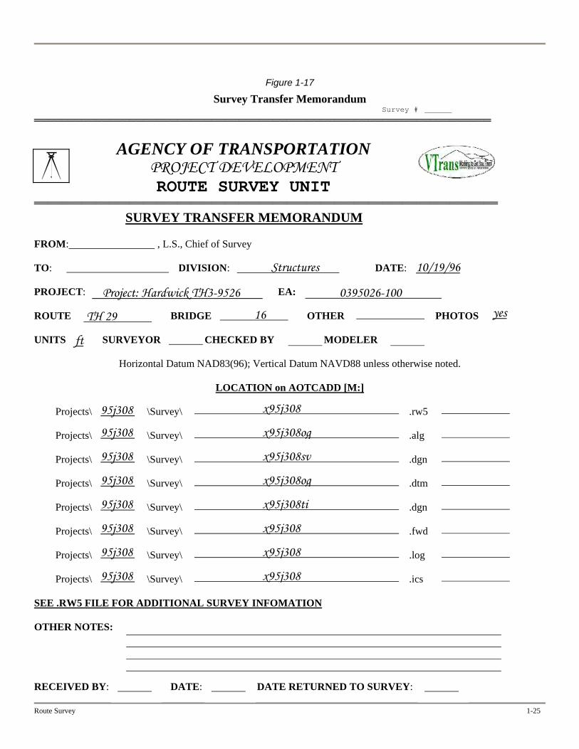
Figure 1-17
Survey Transfer Memorandum Survey # ═══════════════════════════════════════════════════════════════════
AGENCY OF TRANSPORTATION PROJECT DEVELOPMENT ROUTE SURVEY UNIT
════════════════════════════════════════════════════════════════════ SURVEY TRANSFER MEMORANDUM FROM: , L.S., Chief of Survey TO: DIVISION: DATE: PROJECT: EA: ROUTE BRIDGE OTHER PHOTOS UNITS SURVEYOR CHECKED BY MODELER
Horizontal Datum NAD83(96); Vertical Datum NAVD88 unless otherwise noted.
LOCATION on AOTCADD [M:]
Projects\ \Survey\ \ ............ .rw5
Projects\ \Survey\ \ ............ .alg
Projects\ \Survey\ \ ............ .dgn
Projects\ \Survey\ \ ............ .dtm
Projects\ \Survey\ \ ............ .dgn
Projects\ \Survey\ \ ............ .fwd
Projects\ \Survey\ \ ............ .log
Projects\ \Survey\ \ ............ .ics SEE .RW5 FILE FOR ADDITIONAL SURVEY INFOMATION OTHER NOTES: RECEIVED BY: DATE: DATE RETURNED TO SURVEY:
Route Survey 1-25
Structures 10/19/96
Project: Hardwick TH3-9526 0395026-100
TH 29 16 yes
ft
x95j308 95j308
x95j308og 95j308
x95j308sv 95j308
x95j308og 95j308
x95j308ti 95j308
x95j308 95j308
x95j308 95j308
x95j308 95j308
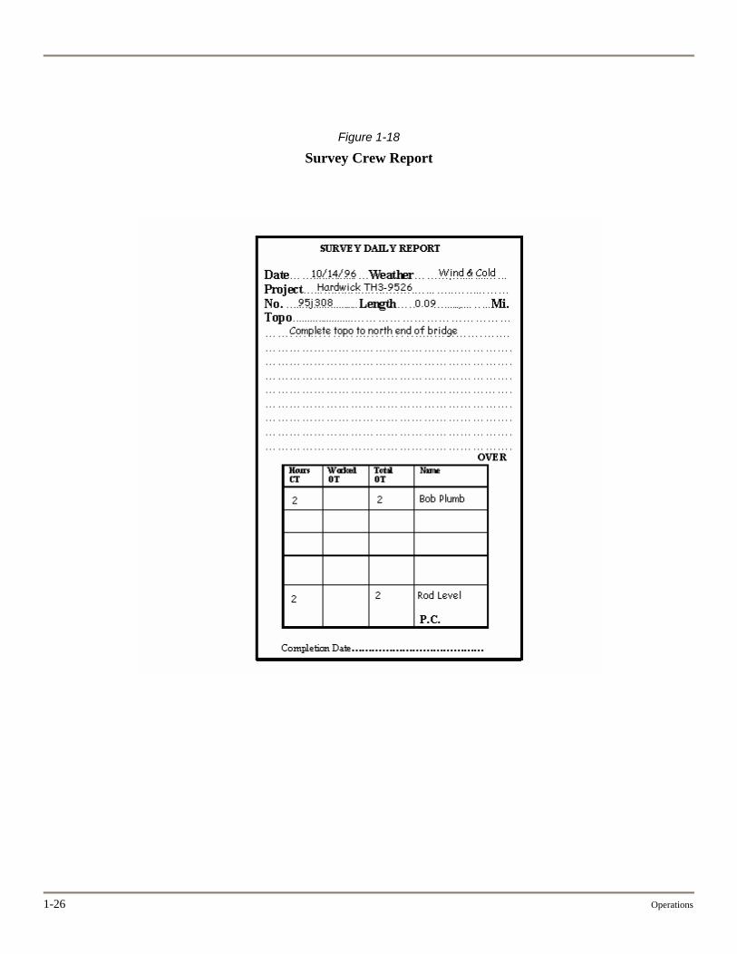
Figure 1-18
Survey Crew Report
1-26 Operations
Chapter Two
.
Equipment
OPERATOR MANUALS
Refer to the operator’s manual for the equipment you are using for details of operation, maintenance, troubleshooting, and other information. Keep the operator’s manuals with the equipment.
CARE OF EQUIPMENT
Overall guidance for equipment care is below.
Inspect all equipment at the start of the day for physical condition and cleanliness. Clean the exterior of equipment frequently.
Keep equipment in padded cases if not in use.
Handle instruments only by the designated grip points.
Secure the positioning of instruments around traffic or construction equipment. Use cones or a vehicle to delineate the position.
Don’t leave an instrument standing alone during high winds. It may throw the instrument off level or topple it.
Don’t attempt to repair an instrument. Take it to a qualified repair shop.
Care of total stations is covered later in this chapter of the manual. Additional guidance for specific equipment units is below.
Check prisms daily to ensure that they are not cracked, are in their assemblies correctly, and are clean.
Don’t charge NiCad batteries unless they have completely discharged.
Route Survey 2- 1
ADJUSTMENT AND MAINTENANCE OF EQUIPMENT
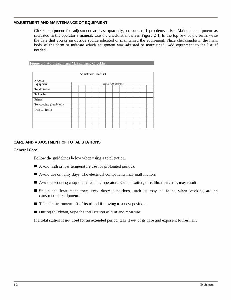
Check equipment for adjustment at least quarterly, or sooner if problems arise. Maintain equipment as indicated in the operator’s manual. Use the checklist shown in Figure 2-1. In the top row of the form, write the date that you or an outside source adjusted or maintained the equipment. Place checkmarks in the main body of the form to indicate which equipment was adjusted or maintained. Add equipment to the list, if needed.
Figure 2-1 Adjustment and Maintenance Checklist
Adjustment Checklist
NAME: Dates of AdjustmentEquipment
Total Station Tribrachs Prisms Telescoping plumb pole Data Collector
CARE AND ADJUSTMENT OF TOTAL STATIONS
General Care
Follow the guidelines below when using a total station.
Avoid high or low temperature use for prolonged periods.
Avoid use on rainy days. The electrical components may malfunction.
Avoid use during a rapid change in temperature. Condensation, or calibration error, may result.
Shield the instrument from very dusty conditions, such as may be found when working around construction equipment.
Take the instrument off of its tripod if moving to a new position.
During shutdown, wipe the total station of dust and moisture.
If a total station is not used for an extended period, take it out of its case and expose it to fresh air.
2-2 Equipment

Route Survey 2- 3
Field Checks
Prior to working on a project, check the total station with two GPS points used for providing control. Compare the inverse with the accepted distance between the points.
Calibration Base Lines
Check total stations with a calibrated base line quarterly, before major projects, or if field checks indicate it’s needed. Use the total station’s most accurate mode during the check. Proceed as follows:
Adjust the tribrach and ensure that the total station is properly secured on the tribrach.
Adjust the collimation.
Telescoping prism pole: adjust bubble and check for worn-down point.
Measure the base line.
Use software such as Calibrate to reduce and analyze measurements and, thus, verify PPM ratings.
Send the instrument in for adjustment if the recommended tolerances are exceeded.
Adjustment Documentation
Field checks and checks with calibration base lines should always be documented. The documentation can be extremely valuable in court testimony regarding the integrity of surveys.
ADJUSTMENT OF AUTOMATIC LEVELS
The main adjustment is to make the circular bubble center when the azimuth axis is vertical. The compensator is most accurate in correcting for the tilt of the telescope when the azimuth axis is vertical.
The line of sight seldom gets out of adjustment. It should be adjusted only when the circular level is in proper adjustment.
Adjustment Setup
Choose a firm support for the instrument. Usually, a firm support can be found only outdoors. The floor of a building, even a concrete floor, deflects if the observer moves around the instrument.
Choose a cloudy day, if practicable. If the sun is shining, work in the shade but in good light.
Allow the level between 30 and 60 minutes to accommodate itself to the temperature. The time depends on the temperature difference between the test site and storage area.
Watch for creep. Creep is caused by settlement of the tripod or a change in the temperature of the instrument. After setting a bubble or the line of sight, let the level stand for a few seconds to see that no movement occurs.
2-4 Equipment
Circular Level
Test of the Circular Level
Turn the telescope in azimuth until it’s parallel to a pair of leveling screws. Center the bubble. Turn the telescope 180 degrees until it’s parallel to the same leveling screws. If the bubble does not remain centered, adjustment is needed.
Adjustment of the Circular Level
1. Unscrew the lock ring at the base of the observation prism and remove the prism unit. If the instrument is not equipped with an observation prism, unscrew the adjusting screw-guard ring that surrounds the circular level.
2. Locate the three slotted-head adjusting screws. The circular vial is supported by a resilient washer that forces it upward against the screws. With a screwdriver, loosen or tighten all of the screws until they are finger-tight.
3. Repeat the test in the previous section, as the bubble may be thrown farther out of adjustment.
4. If the bubble fails to center, bring it halfway to the center with the leveling screws. Bring it to the center by tightening the most logical adjusting screws. Don’t loosen any of the adjusting screws.
5. Turn the telescope 180 degrees in azimuth until it’s parallel with the same set of leveling screws. If the bubble fails to center, bring it halfway to the center with the leveling screws. Bring it to the center by tightening the most logical adjusting screws.
6. Repeat the test and, if needed, the adjustment until the bubble remains centered.
7. When the adjustment is completed, all of the screws must be firm but not tight.
Line of Sight
Test for Line of Sight
The test checks whether the line of sight using the cross hairs is parallel to the axis of the level-bubble tube. Figure 2-2 diagrams the test setups.
1. Place two stakes about 200 to 300 feet apart.
2. Set up midway between the points and take rod readings on both points.
3. Calculate the true difference in elevation by subtracting the two readings. Any error in the line of sight will cancel out because you set up midway between the two points.
4. Set up at one of the points so that the eyepiece just touches the rod when it is placed on the point.
5. Take a rod reading by looking through the objective end of the telescope at the rod held on the point
closest to the setup. Slide a pencil along the rod to help determine the reading.
6. Take the second rod reading in a normal manner for the point 200 to 300 feet away.
7. Calculate the apparent difference in elevation by subtracting the two readings.
8. Calculate the error by subtracting the true and apparent differences in elevation.
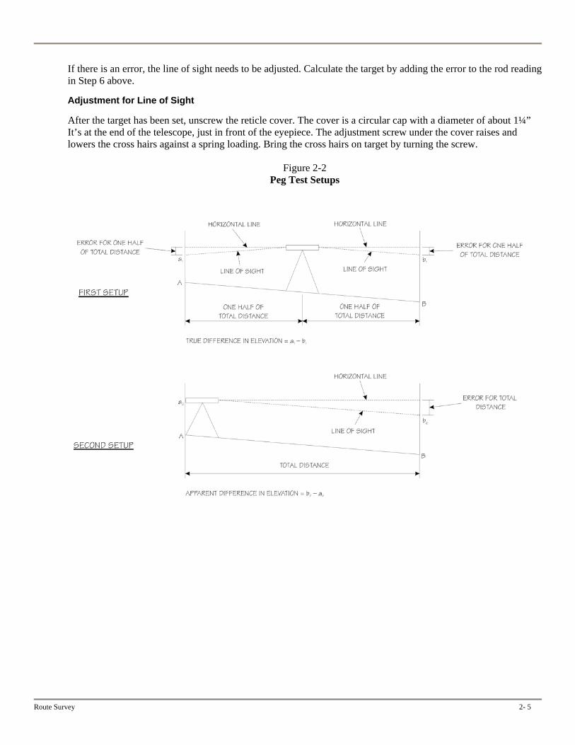
If there is an error, the line of sight needs to be adjusted. Calculate the target by adding the error to the rod reading in Step 6 above.
Adjustment for Line of Sight
After the target has been set, unscrew the reticle cover. The cover is a circular cap with a diameter of about 1¼” It’s at the end of the telescope, just in front of the eyepiece. The adjustment screw under the cover raises and lowers the cross hairs against a spring loading. Bring the cross hairs on target by turning the screw.
Figure 2-2 Peg Test Setups
Route Survey 2- 5

Chapter Three
Quality Control
BLUNDERS
A blunder is a mistake. It may lead to other errors, especially if computer software is involved. A blunder may have occurred if you notice unusual data entries generated electronically.
The best way to check the quality of a survey is to view it graphically. Consider the following sources of blunders when a survey is obviously incorrect:
Communicating poorly within the survey party
Misunderstanding a call-out
Recording all rod height changes
Inputting data incorrectly (wrong coordinates, HI, unit of measurement, etc.)
Misidentifying descriptions
Recovering the wrong point
Misidentifying point numbers (occupying or backsight)
Shooting off the wrong object (a vehicle taillight, for example)
Failing to set the backsight to zero
Going in the wrong direction when making an offset center-shot
Setting prism offsets incorrectly
Setting up the instrument incorrectly (not attaching the instrument to the tribrach securely, for example)
Allowing the telescoping rod height to slip unnoticed
Sighting through glass, such as a car window
Route Survey 3-1
3-2 Quality Control
CLASSIFICATION OF ERRORS
Errors are classified as systematic or random.
Systematic errors can be predicted in both magnitude and sign. They can be corrected by following the recognized correction procedures. For example, changes in atmospheric conditions can be corrected by proper setting of parts per million in the instrument.
Random errors cannot be predicted in either magnitude or sign. They are introduced into each measurement because no human can perform perfectly. Fortunately, they tend to cancel each other mathematically, giving the appearance of accurate work. However, random errors from careless or unskilled work can cause problems.
SOURCES OF ERROR
There are three primary sources of error: instrument, human, and natural.
Instrument Errors
Level Bubbles and Optical Plummet
Normal measuring procedures do not compensate for maladjustment of either the plate bubbles or the optical plummet. These components must be checked more frequently than others.
On control traverse projects, check the optical plummet. Check the plate bubbles routinely on each setup. If you detect error, set the bubbles for the mean of the error or adjust the bubble. Refer to the manual supplied with the instrument.
Double Centering
Double centering compensates for lack of adjustment of almost all components of an instrument. You should make double centering standard practice for all angles measured with a transit, theodolite or total station. Make a minimum of two observations, one direct and one reverse. Then use the mean position.
Parallax
Parallax occurs if the focal point of the eyepiece doesn’t coincide with the plane of the cross hairs. The condition varies for each observer because the focal length depends in part on the shape of the observer’s eyeball. Parallax is also a major concern in the optical plummet.
Check for parallax if you begin to operate a new instrument or one that has been operated by someone else. Check the optical plummet on every setup, particularly if the HI is significantly different from the last setup.
To check for parallax, focus the telescope on some well-defined distant object. Slowly move your head back and forth, about 1 inch from the eyepiece, while watching the relationship of the object to the cross hairs. If the object appears to move, parallax exists.
To eliminate parallax, rotate the knurled eyepiece ring until the cross hairs are the thickest and blackest, refocus the instrument, and check for parallax as described earlier. If parallax still exists, repeat the procedure.
Human Errors
Instrument Setups
Use the guidelines below for setting up an instrument.
Route Survey 3-3
Be sure the tripod is in good condition and all hardware is snugly fitted.
Push the tripod shoes firmly into the ground. Don’t stamp on the tripod feet. Pressure should be parallel to each leg.
Place the legs in positions that result in a minimum of walking around the setup.
In windy conditions, set one leg downwind to gain additional stability.
On hillsides, set two legs downhill.
If the ground is soft or muddy, drive 2” × 10” wedges into the ground to support the tripod legs. Use boards to support the instrument operator.
If the ground is frozen, use flat boards for the legs or, if possible, pile snow around the legs to prevent settling.
If setting up on hot pavement, use flat boards for the legs to prevent settling.
Be sure that the instrument is attached to the tribrach and that all screws are tightened.
Be sure the instrument is exactly over the point.
Check the optical plummet after the instrument is set up and just before moving to another point. If the instrument has moved, check the angle just measured.
Recheck the instrument level. The bubble should remain within one graduation when the instrument is smoothly turned through one circle (if the instrument is shaded).
Setting Sights
If tribrach-mounted targets are used, take the same precautions as if setting up an instrument. “Leap Frogging” between targets and total station (and vice versa) greatly decreases the effects of plumbing errors in traverse closures. Leap frogging is especially beneficial in short-course traverses.
Leap frogging is the traverse procedure in which backsight, instrument point and foresight alternate setting on the same points. If a tribrach is set over a point, it stays mounted on the tripod over that point for all uses. The instrument and sights are transferred from point to point without disturbing the tribrach setup. This is standard procedure for the control traverse.
Use these guidelines for setting sights:
Always check a backsight before picking up, to see that it has not changed.
If you’re setting a pole sight, plumb it with a precision equal to that required for the total survey. Sight as close to the ground as possible for the most accurate angular sighting.
If a sight is set near ground level, check the line of sight for obstructions or for excessive heat waves. On very sunny days, avoid using ground-level sights.
Cross Hair Use
Sight each object with the same part of the cross hair, preferably near the center of the field of view. This practice minimizes small residual adjustment errors.
3-4 Quality Control
The human eye can estimate the center of a wide object more accurately than it can line up two objects. For this reason, use different pointing techniques, depending on the type and apparent size of the sight in the telescope.
If you’re pointing on narrow sights, such as the center of a red-and-white target or a distant range pole, straddle the sight with the double cross hairs. If you’re pointing on wide sights, such as a lath or a range pole at close range, split the sight with the single cross hair.
Measuring Angles
Measure angles as rapidly and as comfortably possible, with a uniform rhythm. Take the first reading at an object, rather than fidgeting with the tangent screw trying to improve the pointing. Too much pointing time increases the probability of error through instrument settlement or atmospheric changes. However, don’t cultivate speed at the expense of good results. Accuracy is more important than speed.
Communication
Carefully call out and report information to be recorded so that blunders are avoided.
Field Notes
If you are using an electronic data collector, don’t input any measurements manually.
You can catch many inconsistencies by carefully analyzing the observations. These items should be checked in the field by the recorder, if you are using paper notes, and always checked in the office. Examples are:
Spreads between the seconds of direct and reverse readings should be consistent and in the same direction throughout the set.
The sums of the direct and reverse zenith angles should be consistent.
When the direct and reverse observations of a position are in different minutes, be sure the average second value is coupled with the correct minutes value.
Natural Factors
Differential Heat
Bright sunlight striking certain parts of the instrument may cause differential expansion of the metal components of the instrument, resulting in small errors.
Heat Waves
On a hot or sunny day, heat waves can cause distortion of lines of sight near a reflecting surface. Stop performing control traverses if excessive heat waves are present.
Phase
If a sight is not evenly lighted on both sides, an instrument operator tends to point toward one side. This phenomenon, called “phase,” can be reduced by using a target with a flat surface pointed directly toward the instrument. The targets attached to the prism are useful in reducing phase.
Refraction
If light waves pass from a medium of one density into a medium of a different density, the rays change in direction (bend). The change in direction is called “refraction.” Because sight lines are light rays, they are refracted, or bent, by changes in the atmosphere, causing small errors in angular measurement.
Route Survey 3-5
Lateral refraction is insignificant in most surveys, but its effects can be minimized further by understanding and avoiding situations producing the largest refraction of line of sight. Some of these situations are:
When the sun shines on a barren, dark surface, the surface warms relatively quickly. This warms the air, and if calm, it produces a column of warm, light air rising from the surface. Examples—
Dark, freshly plowed fields lying between lighter-colored areas of growing crops Large paved areas, such as roadways, runways, and parking lots Clear areas between heavy forests Large bodies of warm water between land areas
Open valleys bordered by bluffs on either side can result in refraction. If a line must pass over a valley, set the observation points as far back from the edges of the valley as possible.
Air tends to layer parallel to the slopes of embankments or the bases of foothills.
If refraction is probable in angles to be measured or is suspected in angles that have been measured, recon the survey area and plan station locations to avoid the problem conditions listed above.

Chapter Four
Traversing and Leveling
This chapter covers control traverses and bench runs, as well as general information that applies to all traversing and leveling. Specific information about surveys other than control traverses or bench runs can be found in Chapter Five, “Topography,” and Chapter Six, “Other Surveys,” which covers right-of-way surveys, airport surveys, and surveys for construction
Chapter One, “Operations,” discusses the research that occurs prior to control traverses and bench runs.
TRAVERSING
Accuracy
A minimum accuracy for a control traverse is 1:20,000. If practicable, improve accuracy by:
Turning a set (direct and reverse) for each angle that you measure. The tolerance is 10 seconds between the angles in a set.
Measuring each line twice.
Configuration
In general, all traverses should be closed. It may not be practical, however, to close all side-line traverses.
The legs of control traverses should be as long as possible but still be useful for topography and, if needed, trigonometric levels.
Monumentation
Mark traverse points with reinforcing bars and plastic caps, if practicable. Reinforcing bars should be a minimum 7/8” diameter (No. 19M) and 3 feet long, with a drill hole or plastic cap set flush with or below ground level. Use wooden hubs if underground obstructions are likely. PK nails may be used in pavement. Traverse monumentation should be out of harm’s way and protected for future use.
At least two marks on a job must be permanent or semipermanent. Reinforcing bars are considered semipermanent.
For control traverses, two or three marks for each project should be tied to the state plane coordinate system.
Meteorological Readings
If running a control traverse with a total station, take the temperature and barometric pressure readings at the beginning of the day and when temperature or pressure changes seem significant, such as when a storm front approaches. Apply the corrections to the distances.
Route Survey 4-1
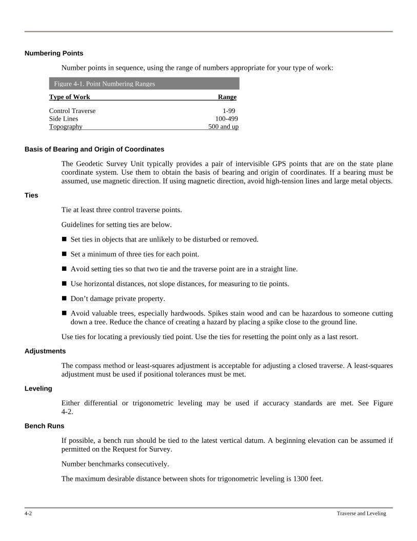
Numbering Points
Number points in sequence, using the range of numbers appropriate for your type of work:
Figure 4-1. Point Numbering Ranges
Type of Work Range
Control Traverse 1-99 Side Lines 100-499 Topography 500 and up
Basis of Bearing and Origin of Coordinates
The Geodetic Survey Unit typically provides a pair of intervisible GPS points that are on the state plane coordinate system. Use them to obtain the basis of bearing and origin of coordinates. If a bearing must be assumed, use magnetic direction. If using magnetic direction, avoid high-tension lines and large metal objects.
Ties
Tie at least three control traverse points.
Guidelines for setting ties are below.
Set ties in objects that are unlikely to be disturbed or removed.
Set a minimum of three ties for each point.
Avoid setting ties so that two tie and the traverse point are in a straight line.
Use horizontal distances, not slope distances, for measuring to tie points.
Don’t damage private property.
Avoid valuable trees, especially hardwoods. Spikes stain wood and can be hazardous to someone cutting down a tree. Reduce the chance of creating a hazard by placing a spike close to the ground line.
Use ties for locating a previously tied point. Use the ties for resetting the point only as a last resort.
Adjustments
The compass method or least-squares adjustment is acceptable for adjusting a closed traverse. A least-squares adjustment must be used if positional tolerances must be met.
Leveling
Either differential or trigonometric leveling may be used if accuracy standards are met. See Figure 4-2.
Bench Runs
If possible, a bench run should be tied to the latest vertical datum. A beginning elevation can be assumed if permitted on the Request for Survey.
Number benchmarks consecutively.
The maximum desirable distance between shots for trigonometric leveling is 1300 feet.
4-2 Traverse and Leveling
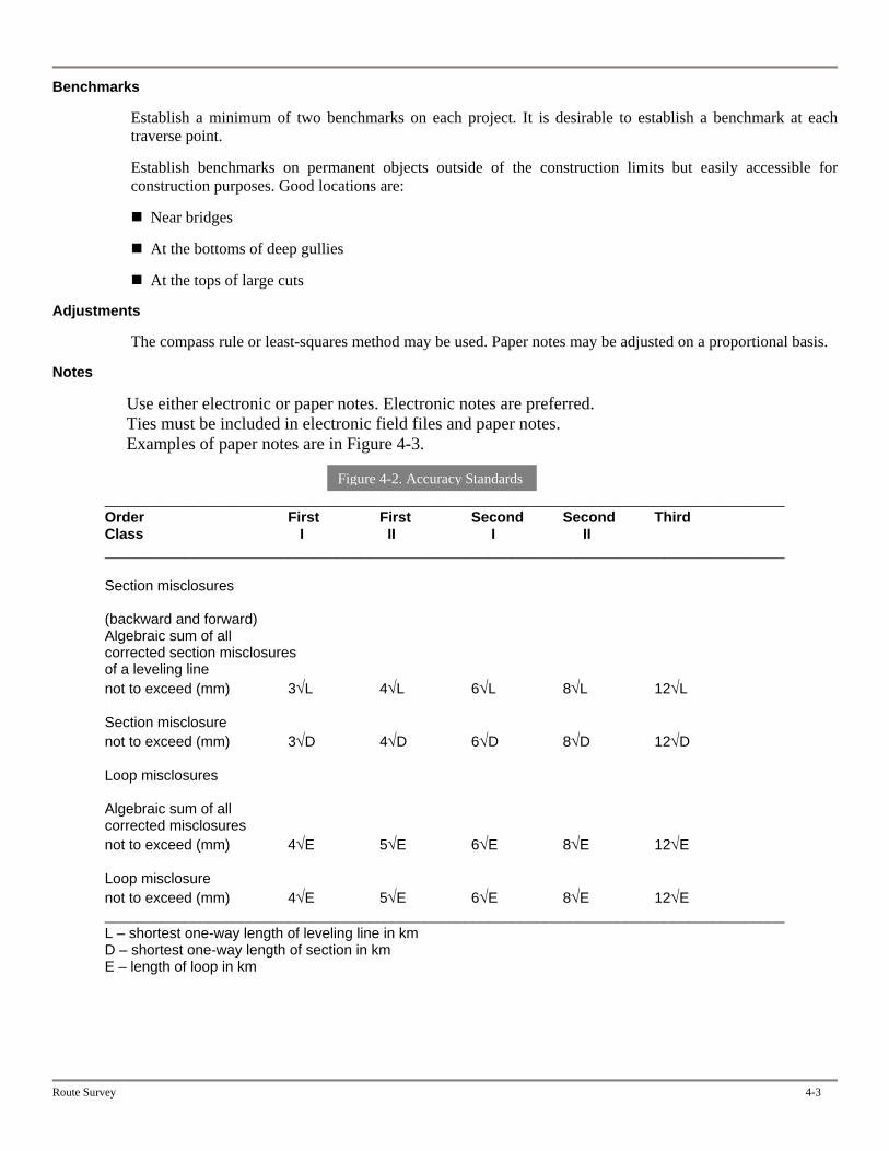
Benchmarks
Establish a minimum of two benchmarks on each project. It is desirable to establish a benchmark at each traverse point.
Establish benchmarks on permanent objects outside of the construction limits but easily accessible for construction purposes. Good locations are:
Near bridges
At the bottoms of deep gullies
At the tops of large cuts
Adjustments
The compass rule or least-squares method may be used. Paper notes may be adjusted on a proportional basis.
Notes
Use either electronic or paper notes. Electronic notes are preferred. Ties must be included in electronic field files and paper notes. Examples of paper notes are in Figure 4-3.
Route Survey 4-3
_____________________________________________________________________________________
Figure 4-2. Accuracy Standards
Order First First Second Second Third Class I II I II _____________________________________________________________________________________ Section misclosures (backward and forward) Algebraic sum of all corrected section misclosures of a leveling line not to exceed (mm) 3√L 4√L 6√L 8√L 12√L Section misclosure not to exceed (mm) 3√D 4√D 6√D 8√D 12√D Loop misclosures Algebraic sum of all corrected misclosures not to exceed (mm) 4√E 5√E 6√E 8√E 12√E Loop misclosure not to exceed (mm) 4√E 5√E 6√E 8√E 12√E _____________________________________________________________________________________ L – shortest one-way length of leveling line in km D – shortest one-way length of section in km E – length of loop in km
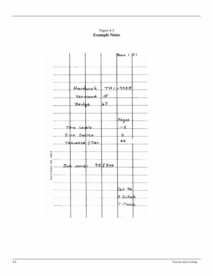
Figure 4-3 Example Notes
4-4 Traverse and Leveling
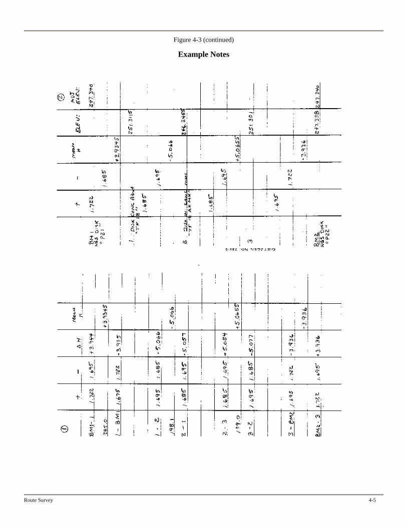
Figure 4-3 (continued)
Example Notes
Route Survey 4-5
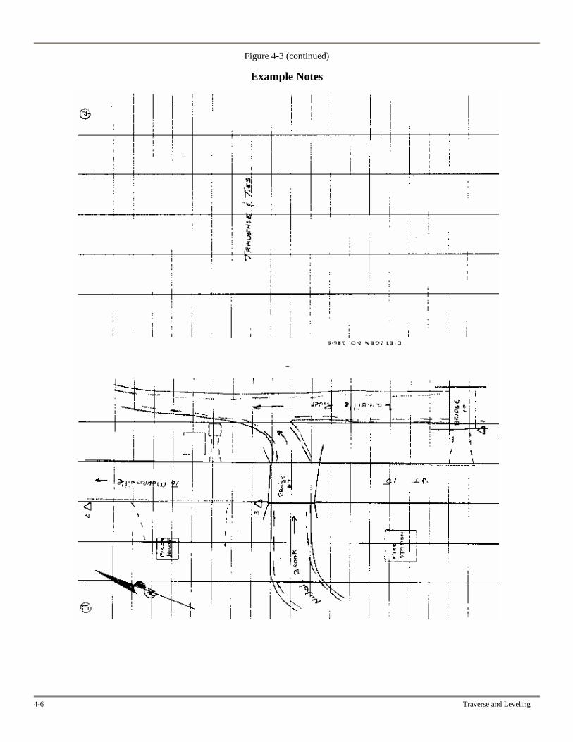
Figure 4-3 (continued)
Example Notes
4-6 Traverse and Leveling
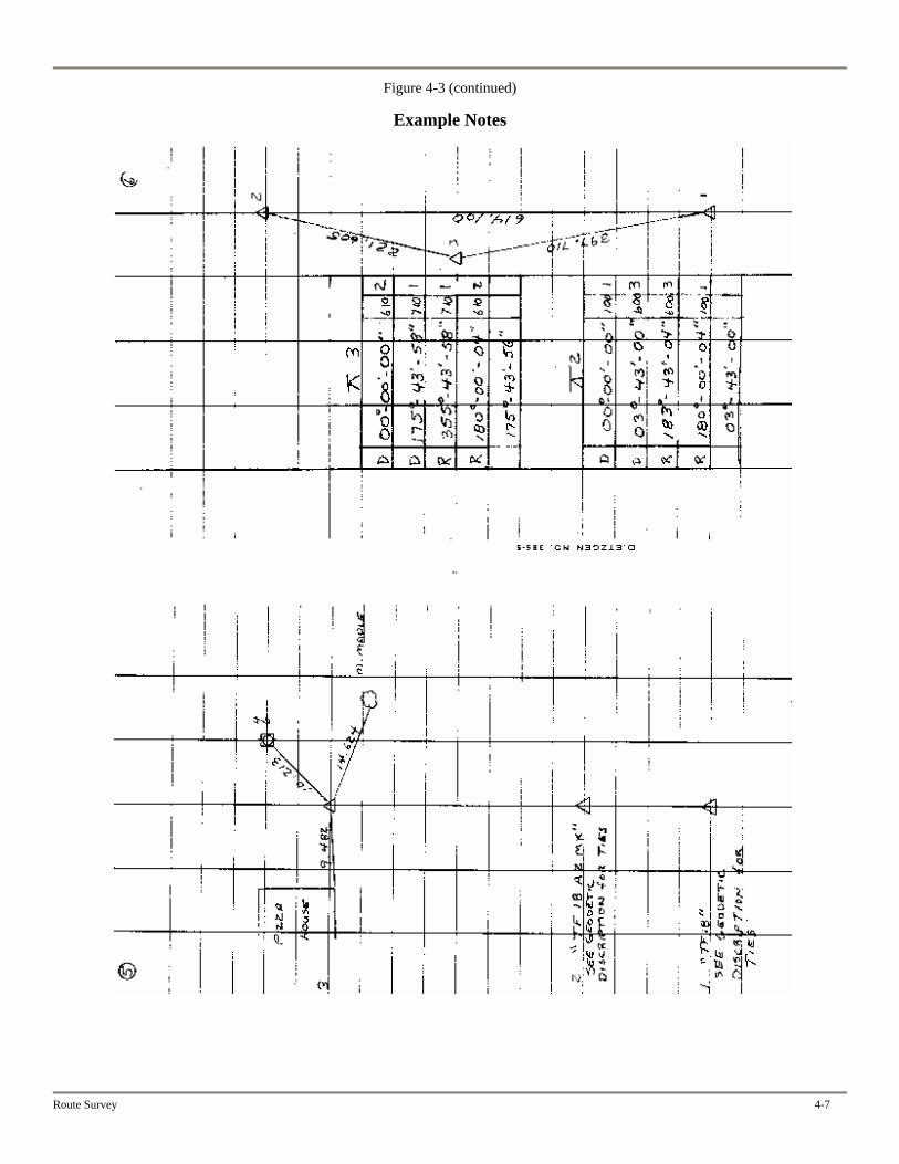
Figure 4-3 (continued)
Example Notes
Route Survey 4-7

Chapter Five
Topography
This chapter describes the procedures for VAOT. Procedures may vary in other organizations according to the equipment and software used.
ACCURACY
Accuracy for topography is based on the control traverse. See Chapter Four, “Traversing and Leveling,” for control traverse accuracy standards. Before any data has been gathered verify the control points that are being occupied are correct by using a backsite check that will check for a difference in distance and elevation.
A shot for topography should be taken at the center of an object.
PREFERENCES
Preferences define the codes and description of topographic features. The VAOT CADD Support Unit issues and maintains preferences. See Appendix A for the list.
The list of preferences indicates which points are included in the DTM (digital terrain model). Other points on the list are included in the topography but not in the triangulated model.
The output of software used for topography must match the DTM software used by the CADD Support Unit. If needed, check with the CADD Support Unit prior to performing a topographic survey.
DEFINITIONS
Random point. A data point with a number, northing, easting, elevation, and description generated from a field survey.
Breakline point. A data point with a number, northing, easting, elevation, and description generated from a field survey and designating segment ends of a breakline.
Breakline. A series of segments connecting breakline points that represents a change of ground slope (for example, the top of slope) or a physical feature (for example, the edge of roadway).
Some breaklines (for example, fences, stone walls, and tree lines) may not represent a change in ground slope but are treated as such in DTM creation. Extra topography shots may be necessary to make an accurate representation of the existing ground surface.
Inferred point. A computer-generated data point interpolated along breakline segments at a specific interval, usually used to densify the model.
Route Survey 5-1
5-2 Topography
DTM (Digital Terrain Model). A computer-generated numerical representation of a ground surface. A surface may not contain any vertical surfaces, overhangs, facets, tunnels, caves, etc.
FIELD PROCEDURES
General Guidelines
The guidelines below apply to DTM modeling regardless of the method that is used to collect data.
A breakline is made up of actual measured data points defining the ground feature. It must be located in sufficiently short segments to accurately represent a curve.
Breaklines are three-dimensional. They shouldn’t cross each other at different elevations. They should only meet or cross at common vertexes.
The DTM software doesn’t recognize vertical faces such as those that may exist for bridge abutments, retaining walls, and curbs. Offset the data measured at the top and bottom of a vertical face.
If breaklines are close together, the best DTM models are built if pairs of points are taken opposite each other, as shown on the next page in Figure 5-1. This will result in fewer crossed breaklines, especially for roadway curves and features with near-vertical surfaces, such as curbs.
Measure data points at intervals of 66 feet or less, regardless of the roadway characteristics or the accuracy of the individual points. Use a 66 foot interval for straight segments of road that have a constant slope. For curves, decrease the length of the interval as the radius of the curve decreases. The midpoint of the chord between two data points must not vary significantly from the curve on the ground.
Figure 5-2, on Page 5-4, illustrates common problems to avoid.
Point Location Guidelines
Use the feature descriptions and point location figures in this section to help determine where to take topographic shots. In general, a data point is needed anywhere the slope of the surface changes. Clarify shots, if needed, with notes in the field file.
“Left” and “Right”
Features can be labeled either “left” or “right.” Determine the label by facing the direction in which the prism is traveling as you take the survey. Figure 5-3, at the end of the chapter, illustrates how to determine “left” or “right.”
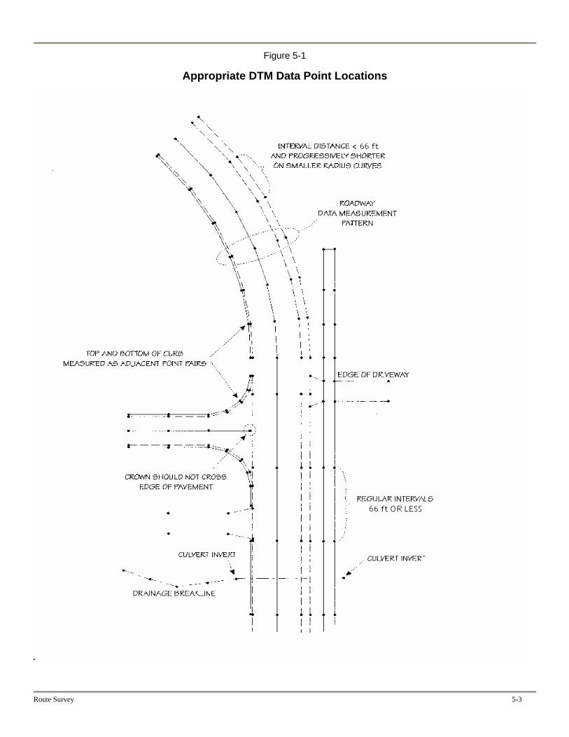
Figure 5-1
Appropriate DTM Data Point Locations
Route Survey 5-3
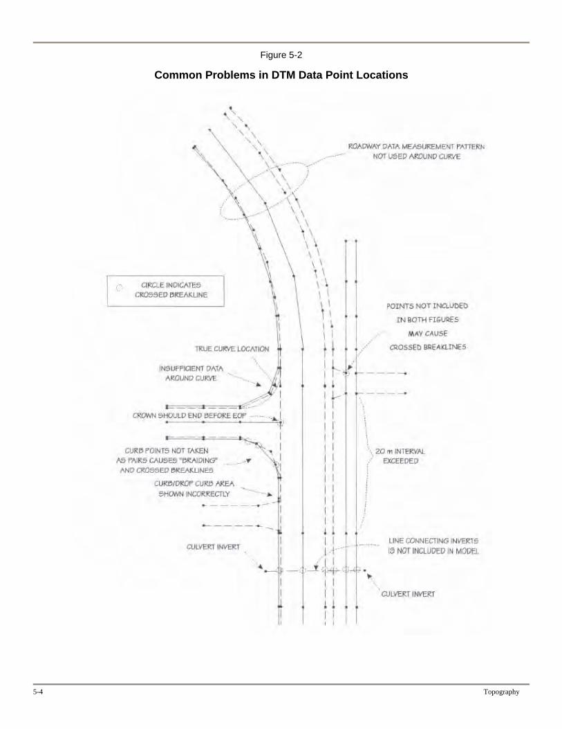
Figure 5-2
Common Problems in DTM Data Point Locations
5-4 Topography
Route Survey 5-5
Location Sketches
Figure 5-4 shows the point locations for a typical rural area. Figure 5-5 shows an urban area.
Curb
For a curb of constant cross section, provide the width. Use the edge of pavement for the bottom of curb and provide data for a breakline along the front edge of the curb.
Intersecting Side Roads
There are many breaklines at the intersection of a side road and the mainline. Don’t cross them. For example, the pavement crown of a side road should end before the edge of pavement for the mainline. Provide additional points for tight radii.
Driveways and Sidewalks
If driveways need to be shown, locate both edges. Locate the crown of the driveway if one exists. Locate the edges of sidewalks if required. Driveways and sidewalks should only cross each other at common points.
Drainage
Figure 5-6 shows the point locations for a drop inlet.
Take shots to determine the size of an underground pipe and any changes in the size.
Steps and Walls
Figure 5-7 shows a retaining wall.
Breakline points for stone walls should be taken at ground elevation on the centerline of the wall. Note the height and width.
Bridges
Figure 5-8 is a bridge deck, Figure 5-9 is an isometric view of a bridge abutment, and Figure 5-10 shows elevation views of a pier and an abutment.
On bridge decks, measure points at expansion joints, piers, and the pavement crown in addition to the standard points.
Figure 5-11 is the end view of a large pipe.
Railroads
Figure 5-12 shows point locations for a railroad.
Subsurface Features
Take surface shots on the marks made by Dig Safe and others.
Photograph Guidelines
Take photographs to supplement and clarify topographic surveys of bridges and channels. Photographs should be taken upstream and downstream of a bridge and of each abutment and pier. Label each photograph on its back with the date, direction of the shot, the subject, and the project number and name. Take photographs of major differences in terrain for any topographic survey. Again, label each photograph on its back with the information listed above.
5-6 Topography
Wetlands
Guidelines
Wetlands should be delineated prior to the survey, if it can be arranged. The VAOT Environmental Section (or consultants employed by them) delineates wetlands.
Don’t label an area as a wetland until it has been delineated by a qualified Environmentalist. You can label an area with standing water as “wet” prior to delineation.
Wetlands typically are not located as a breakline for a ground model.
Definitions
Various types of wetlands are defined below.
Forested wetlands are dominated by trees. There are three types, distinguished by the types of trees that dominate them.
Hardwood forested wetland Softwood forested wetland Mixed forested wetland
Shrub swamps are woody swamps that are dominated by species that are not trees, such as alders and willows. You can identify a shrub swamp by the presence of multistemmed woody vegetation less than 15 feet high.
Emergent wetlands are dominated by nonwoody or grasslike vegetation. An example is a cattail swamp.
Wet meadows tend to be drier than other types of wetlands. They generally are spongy and are often used for agriculture. Examples are wet pastures and hay fields.
Open-water wetlands do not have vegetation protruding through the water surface, although there may be submerged vegetation.
By law, an area with water deeper than three feet is not a wetland.
Historical Sites
The VAOT Technical Services Division decides which areas are historical sites. Planning marks the sites, and Route Survey locates them. It’s desirable that Planning mark the sites prior to the start of a survey.

Figure 5-3
Point Location – “Left” and “Right”
Route Survey 5-7
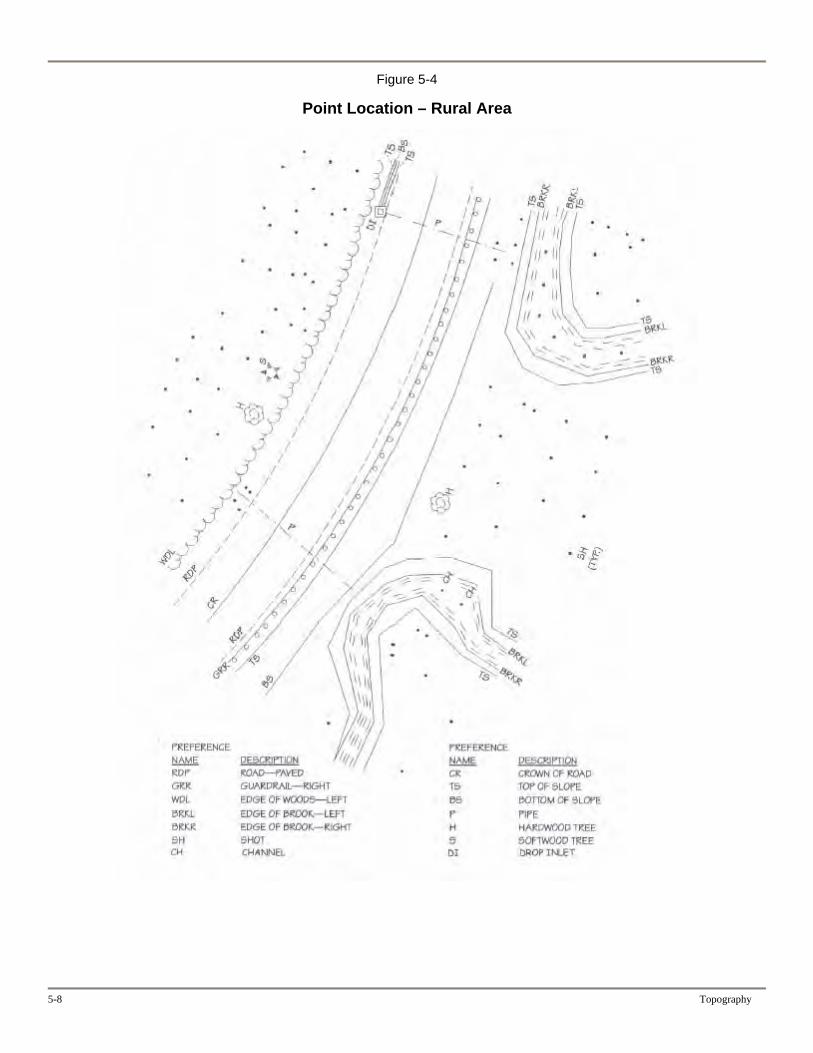
Figure 5-4
Point Location – Rural Area
5-8 Topography

Figure 5-5
Point Location – Urban Area
Route Survey 5-9
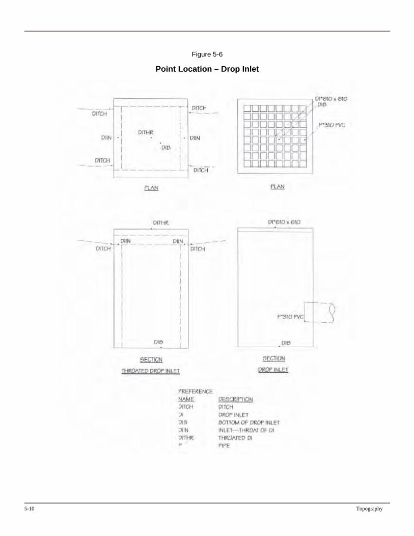
Figure 5-6
Point Location – Drop Inlet
5-10 Topography
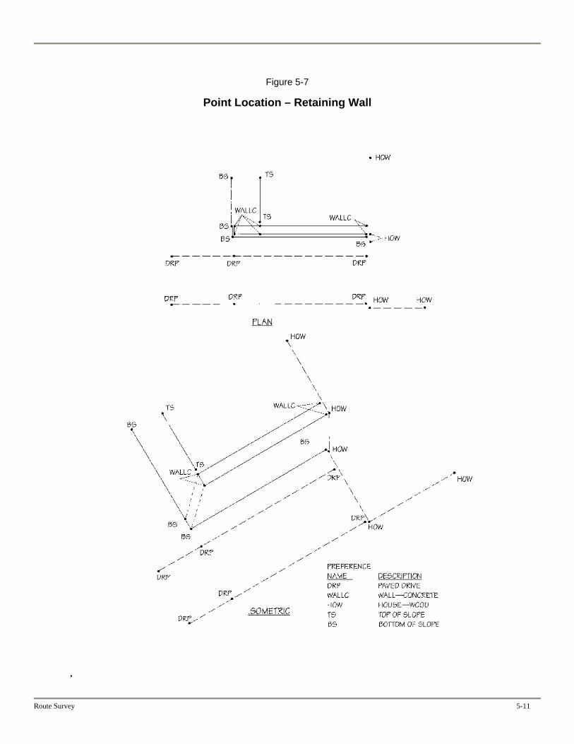
Figure 5-7
Point Location – Retaining Wall
Route Survey 5-11
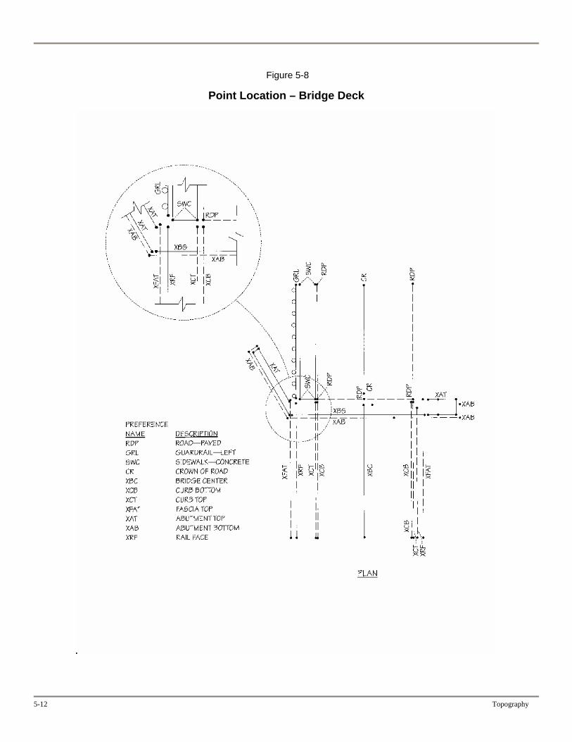
Figure 5-8
Point Location – Bridge Deck
5-12 Topography

Figure 5-9
Point Location – Bridge Abutment
Route Survey 5-13
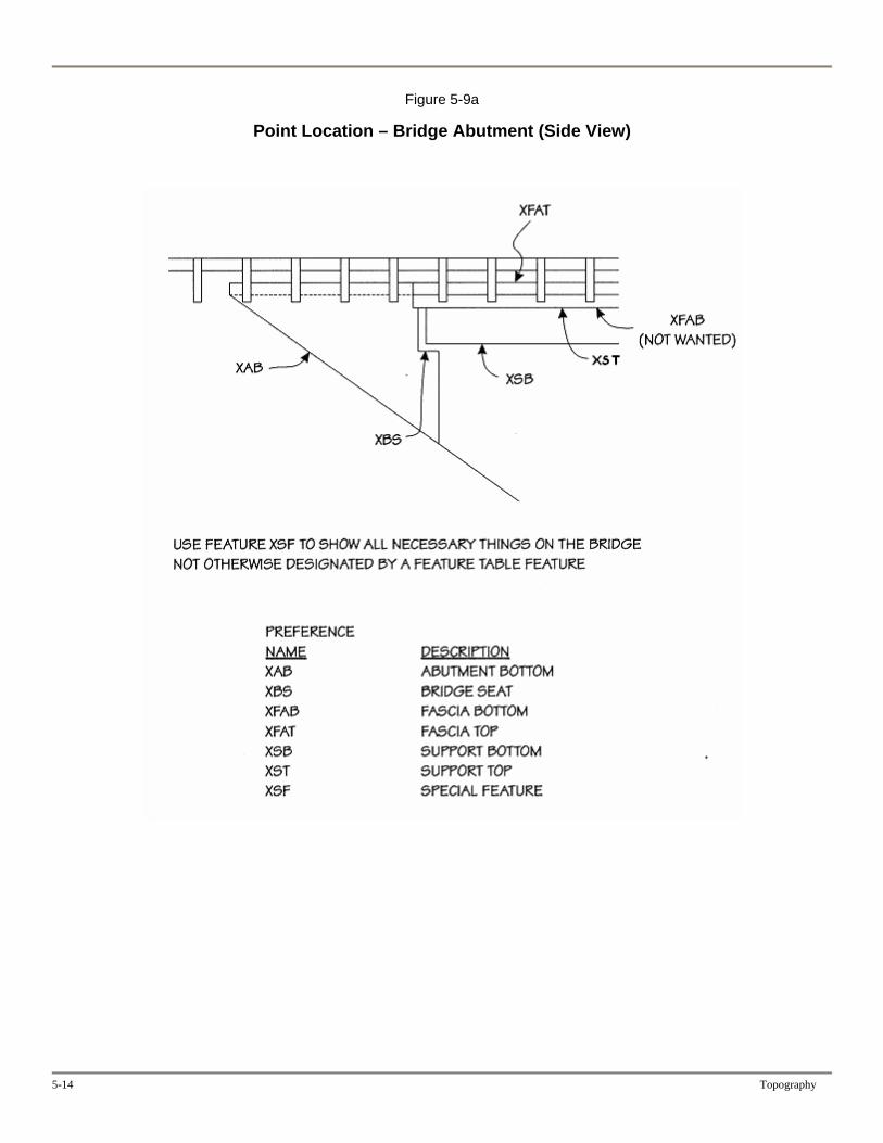
Figure 5-9a
Point Location – Bridge Abutment (Side View)
5-14 Topography

Figure 5-10
Point Location – Pier and Abutment
PIER OVER HANG IS NOT IN THE MODEL
XSF SPECIAL FEATURE (NOT IN THE MODEL)
Figure 5-11
Route Survey 5-15
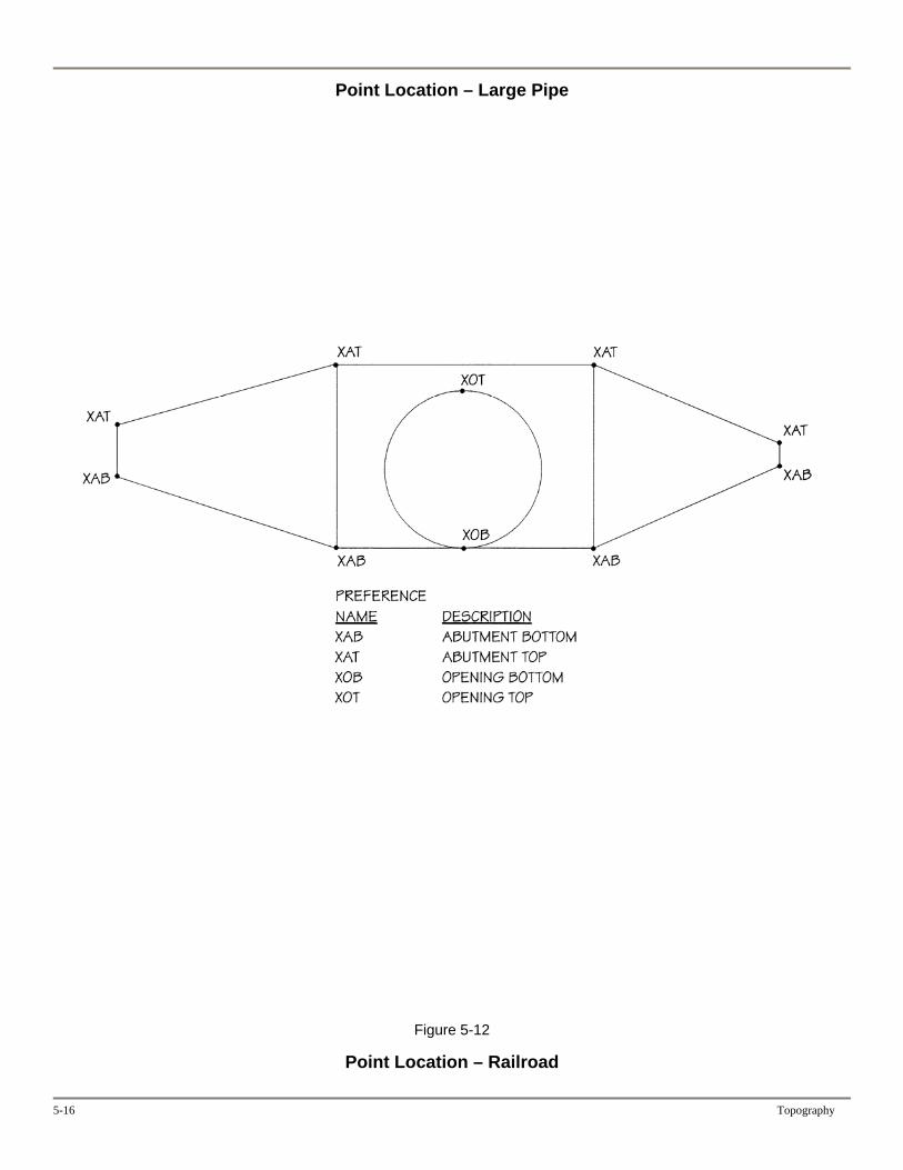
Point Location – Large Pipe
Figure 5-12
Point Location – Railroad
5-16 Topography
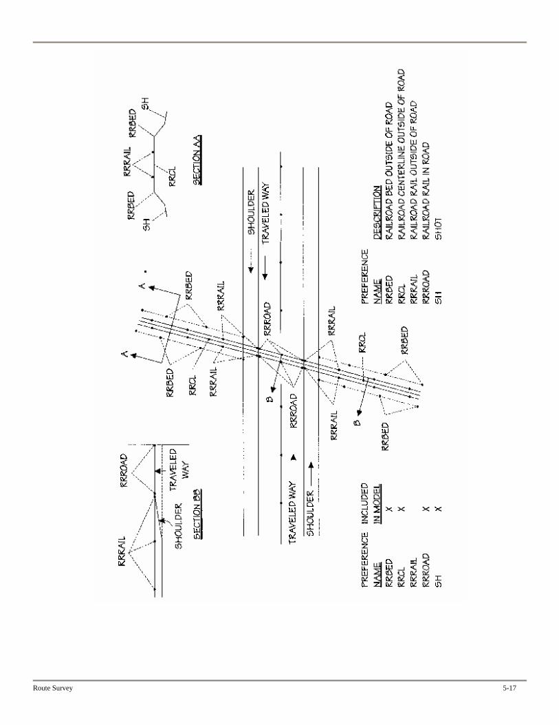
Route Survey 5-17

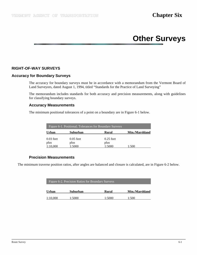
Chapter Six
Other Surveys
RIGHT-OF-WAY SURVEYS
Accuracy for Boundary Surveys
The accuracy for boundary surveys must be in accordance with a memorandum from the Vermont Board of Land Surveyors, dated August 1, 1994, titled “Standards for the Practice of Land Surveying”
The memorandum includes standards for both accuracy and precision measurements, along with guidelines for classifying boundary surveys.
Accuracy Measurements
The minimum positional tolerances of a point on a boundary are in Figure 6-1 below.
Figure 6-1. Positional; Tolerances for Boundary Surveys
Urban Suburban Rural Mtn./Marshland
0.03 feet 0.05 feet 0.25 feet plus plus plus 1:10,000 1:5000 1:5000 1:500
Precision Measurements
The minimum traverse position ratios, after angles are balanced and closure is calculated, are in Figure 6-2 below.
Figure 6-2. Precision Ratios for Boundary Surveys
Urban Suburban Rural Mtn./Marshland
1:10,000 1:5000 1:5000 1:500
Route Survey 6-1
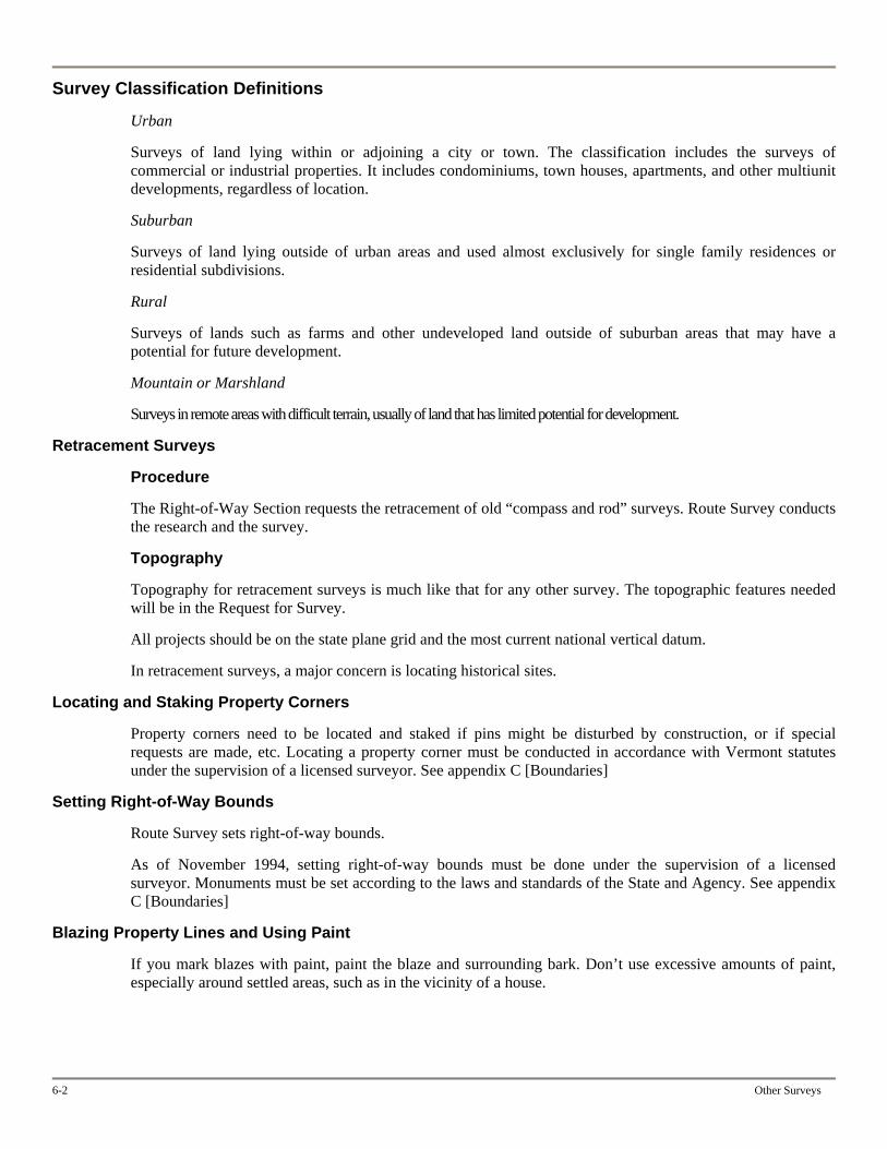
6-2 Other Surveys
Survey Classification Definitions
Urban
Surveys of land lying within or adjoining a city or town. The classification includes the surveys of commercial or industrial properties. It includes condominiums, town houses, apartments, and other multiunit developments, regardless of location.
Suburban
Surveys of land lying outside of urban areas and used almost exclusively for single family residences or residential subdivisions.
Rural
Surveys of lands such as farms and other undeveloped land outside of suburban areas that may have a potential for future development.
Mountain or Marshland
Surveys in remote areas with difficult terrain, usually of land that has limited potential for development.
Retracement Surveys
Procedure
The Right-of-Way Section requests the retracement of old “compass and rod” surveys. Route Survey conducts the research and the survey.
Topography
Topography for retracement surveys is much like that for any other survey. The topographic features needed will be in the Request for Survey.
All projects should be on the state plane grid and the most current national vertical datum.
In retracement surveys, a major concern is locating historical sites.
Locating and Staking Property Corners
Property corners need to be located and staked if pins might be disturbed by construction, or if special requests are made, etc. Locating a property corner must be conducted in accordance with Vermont statutes under the supervision of a licensed surveyor. See appendix C [Boundaries]
Setting Right-of-Way Bounds
Route Survey sets right-of-way bounds.
As of November 1994, setting right-of-way bounds must be done under the supervision of a licensed surveyor. Monuments must be set according to the laws and standards of the State and Agency. See appendix C [Boundaries]
Blazing Property Lines and Using Paint
If you mark blazes with paint, paint the blaze and surrounding bark. Don’t use excessive amounts of paint, especially around settled areas, such as in the vicinity of a house.
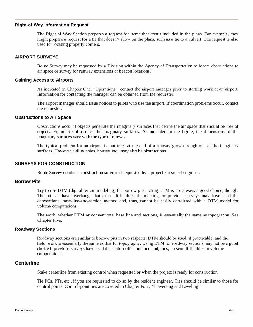
Route Survey 6-3
Right-of Way Information Request
The Right-of-Way Section prepares a request for items that aren’t included in the plans. For example, they might prepare a request for a tie that doesn’t show on the plans, such as a tie to a culvert. The request is also used for locating property corners.
AIRPORT SURVEYS
Route Survey may be requested by a Division within the Agency of Transportation to locate obstructions to air space or survey for runway extensions or beacon locations.
Gaining Access to Airports
As indicated in Chapter One, “Operations,” contact the airport manager prior to starting work at an airport. Information for contacting the manager can be obtained from the requester.
The airport manager should issue notices to pilots who use the airport. If coordination problems occur, contact the requestor.
Obstructions to Air Space
Obstructions occur if objects penetrate the imaginary surfaces that define the air space that should be free of objects. Figure 6-3 illustrates the imaginary surfaces. As indicated in the figure, the dimensions of the imaginary surfaces vary with the type of runway.
The typical problem for an airport is that trees at the end of a runway grow through one of the imaginary surfaces. However, utility poles, houses, etc., may also be obstructions.
SURVEYS FOR CONSTRUCTION
Route Survey conducts construction surveys if requested by a project’s resident engineer.
Borrow Pits
Try to use DTM (digital terrain modeling) for borrow pits. Using DTM is not always a good choice, though. The pit can have overhangs that cause difficulties if modeling, or previous surveys may have used the conventional base-line-and-section method and, thus, cannot be easily correlated with a DTM model for volume computations.
The work, whether DTM or conventional base line and sections, is essentially the same as topography. See Chapter Five.
Roadway Sections
Roadway sections are similar to borrow pits in two respects: DTM should be used, if practicable, and the field work is essentially the same as that for topography. Using DTM for roadway sections may not be a good choice if previous surveys have used the station-offset method and, thus, present difficulties in volume computations.
Centerline
Stake centerline from existing control when requested or when the project is ready for construction.
Tie PCs, PTs, etc., if you are requested to do so by the resident engineer. Ties should be similar to those for control points. Control-point ties are covered in Chapter Four, “Traversing and Leveling.”
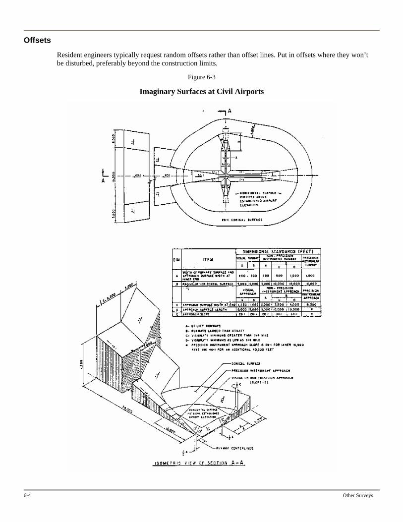
Offsets
Resident engineers typically request random offsets rather than offset lines. Put in offsets where they won’t be disturbed, preferably beyond the construction limits.
Figure 6-3
Imaginary Surfaces at Civil Airports
6-4 Other Surveys

Appendix A
Tables and Formulas
Route Survey A-1
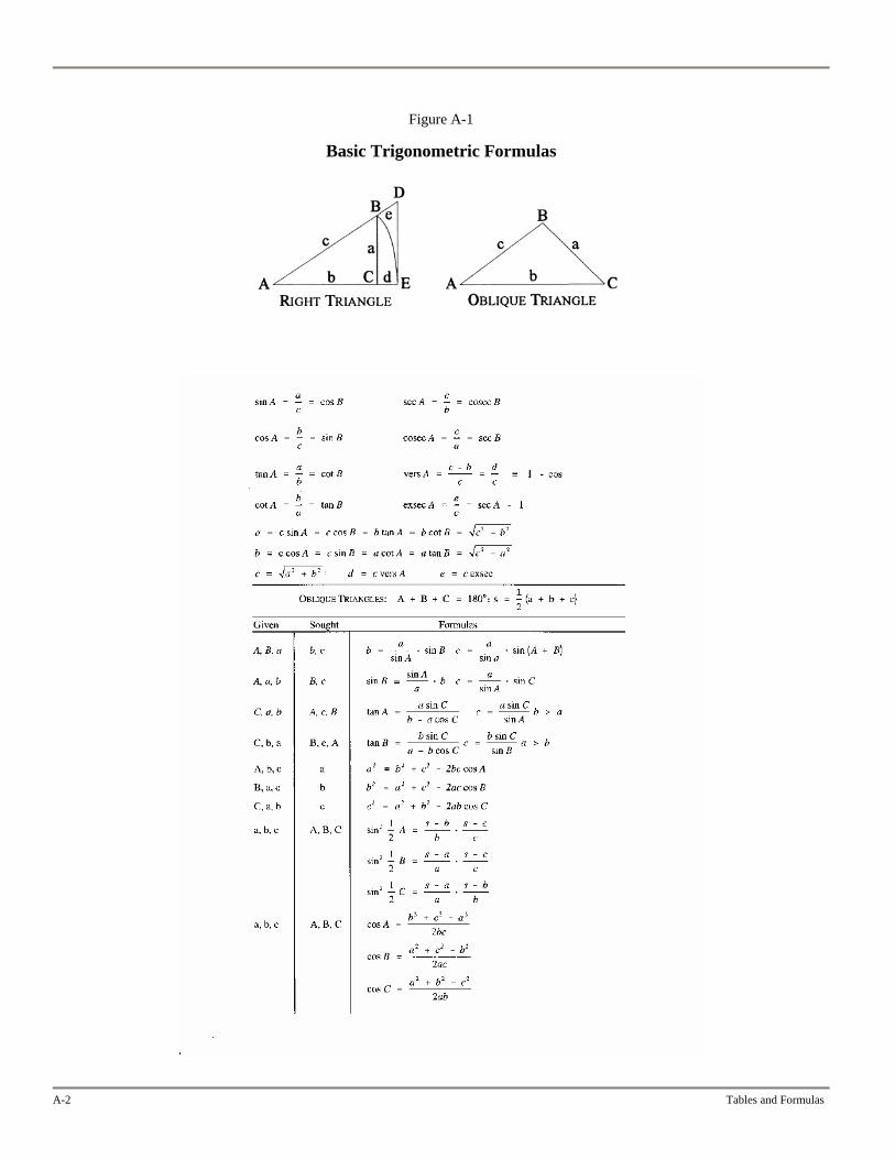
Figure A-1
Basic Trigonometric Formulas
A-2 Tables and Formulas
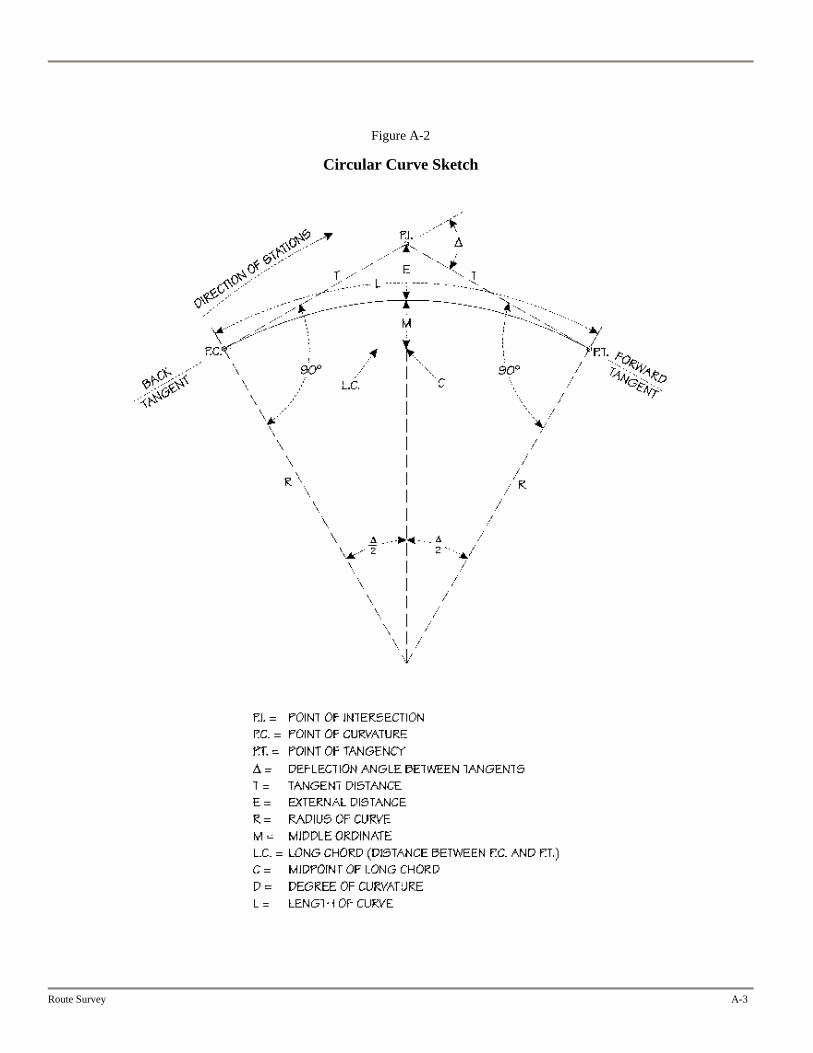
Figure A-2
Circular Curve Sketch
Route Survey A-3
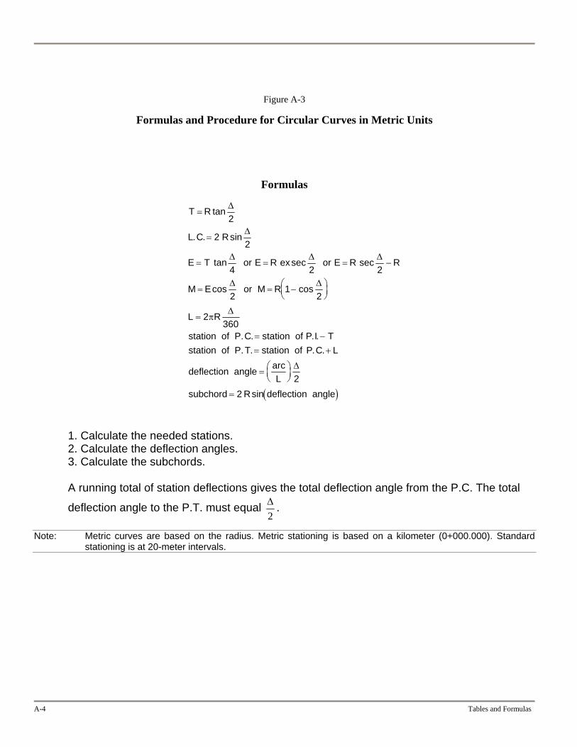
Figure A-3
Formulas and Procedure for Circular Curves in Metric Units
Formulas
( )
T R
L C R
E T E R ex E R R
M E M R
L R
station o P I TP C L
arcL
R
=
=
= = =
= = −⎛⎝⎜
⎞⎠⎟
=
= −= +
= ⎛⎝⎜
⎞⎠⎟
=
tan
. . sin
tan sec sec
cos cos
. . .
. . .
sin
Δ
Δ
Δ Δ
Δ Δ
Δ
Δ
2
22
4 2
21
2
2360
22
or or
or
station of P.C f station of P.T station of
deflection angle
subchord deflection angle
π
−Δ2
1. Calculate the needed stations. 2. Calculate the deflection angles. 3. Calculate the subchords.
A running total of station deflections gives the total deflection angle from the P.C. The total
deflection angle to the P.T. must equal Δ2
.
Note: Metric curves are based on the radius. Metric stationing is based on a kilometer (0+000.000). Standard stationing is at 20-meter intervals.
A-4 Tables and Formulas
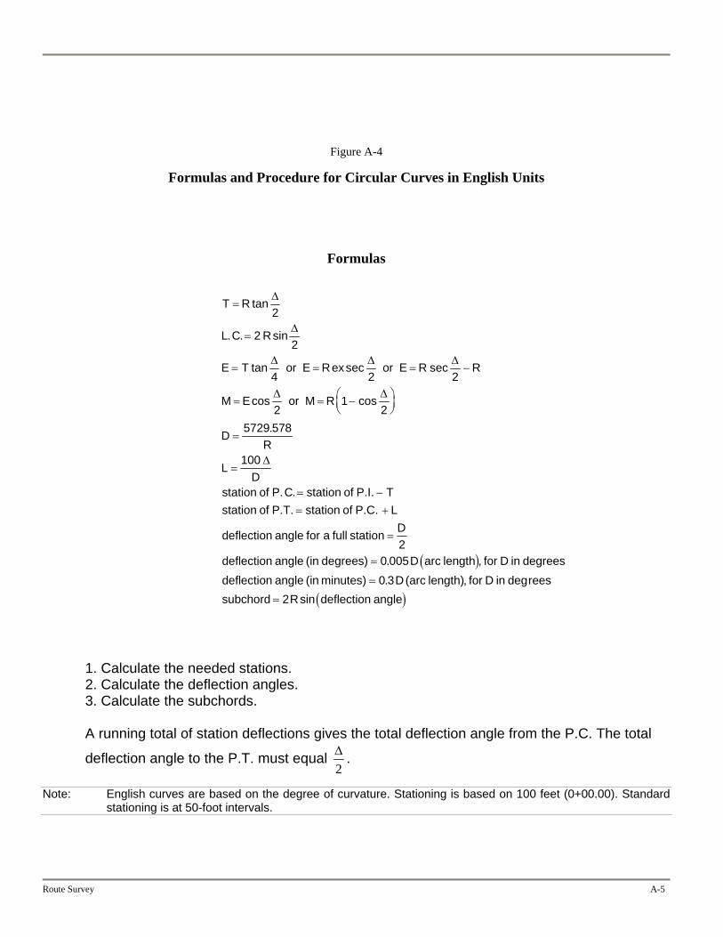
Figure A-4
Formulas and Procedure for Circular Curves in English Units
Formulas
( )
T R
L C R
E T or E Rex or E R R
M E or M R
DR
LD
of P.I. Tstation of P.T. station of P.C. L
deflection angle for a full station D
deflection angle (in . D arc , for D indeflection angle (in . D(arc for D in reessubchord R
=
=
= = = −
= = −⎛⎝⎜
⎞⎠⎟
=
=
= −= +
=
=
=
=
tan
. . sin
tan sec sec
cos cos
.
.
, degsin
Δ
Δ
Δ Δ Δ
Δ Δ
Δ
2
22
4 2 2
21
25729 578
100
20 0050 3
2
station of P.C station
degrees) length degreesminutes) length)deflection( )angle
1. Calculate the needed stations. 2. Calculate the deflection angles. 3. Calculate the subchords.
A running total of station deflections gives the total deflection angle from the P.C. The total
deflection angle to the P.T. must equal Δ2
.
Note: English curves are based on the degree of curvature. Stationing is based on 100 feet (0+00.00). Standard stationing is at 50-foot intervals.
Route Survey A-5
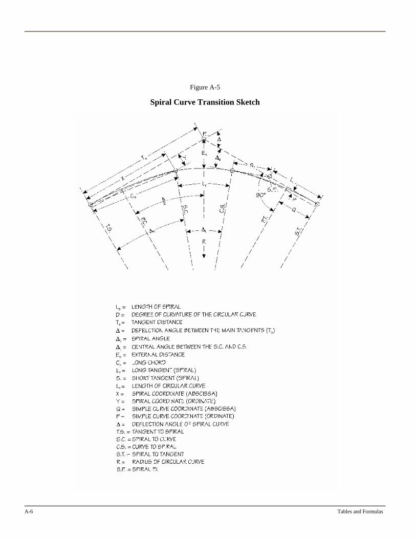
Figure A-5
Spiral Curve Transition Sketch
A-6 Tables and Formulas

Figure A-6
Formulas and Procedure for Spiral Curve Transitions in Metric Units
( )( ) ( )
T R P Q T T Q P
ER P
R E R P ex P
LR
L R
I TS LC LS L
L
s s
s s
ss
c s
cc
s
s
c
s
ss
= + + = + +
=+
− = + +
=
= −
=
= −
= +
= +
= +
≈
=
tan tan
cossec
. . .. .. .
. . .
,
,
Δ Δ
ΔΔ
Δ
Δ Δ Δ
Δ
Δ
2 2
22
90
22
360
3
or
or
station of T.S station of Pstation of S.C. station of Tstation of C.S. station of Sstation of S. T station of C
spiral deflection
deflection angle for distance
π
π
θ
φ l l
ss
⎛
⎝⎜
⎞
⎠⎟
2
θ
1. Calculate the tangent distance. 2. Calculate the spiral curve angle and circular curve angle and arc length. 3. Calculate the key points. 4. Calculate lengths to and deflection angles for the key points.
Note: Metric curves are based on the radius. Metric stationing is based on a kilometer (0+000.000). Standard stationing is at 20-meter intervals.
Route Survey A-7
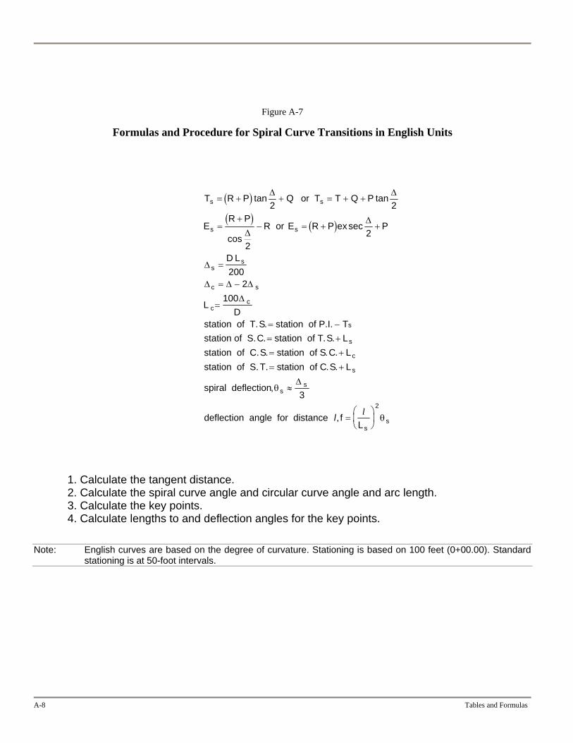
Figure A-7
Formulas and Procedure for Spiral Curve Transitions in English Units
( )( ) ( )
T R P Q T Q P
ER P
R E R P ex P
D L
LD
TS LC LS L
L
s s
s s
ss
c s
cc
s
s
c
s
ss
s
= + + = + +
=+
− = + +
=
= −
=
= −= +
= +
= +
≈
=⎛
⎝⎜
⎞
⎠
tan tan
cossec
.. . .. . .
. .
,
Δ Δ
ΔΔ
Δ
Δ Δ Δ
Δ
Δ
2 2
22
2002
100
3
or T
or
station of T.S station of P.I.station of S.C station of Tstation of C.S station of Sstation of S.T. station of C
spiral deflection
deflection angle for distance , f
θ
l l⎟
2
θs
1. Calculate the tangent distance. 2. Calculate the spiral curve angle and circular curve angle and arc length. 3. Calculate the key points. 4. Calculate lengths to and deflection angles for the key points.
Note: English curves are based on the degree of curvature. Stationing is based on 100 feet (0+00.00). Standard stationing is at 50-foot intervals.
A-8 Tables and Formulas
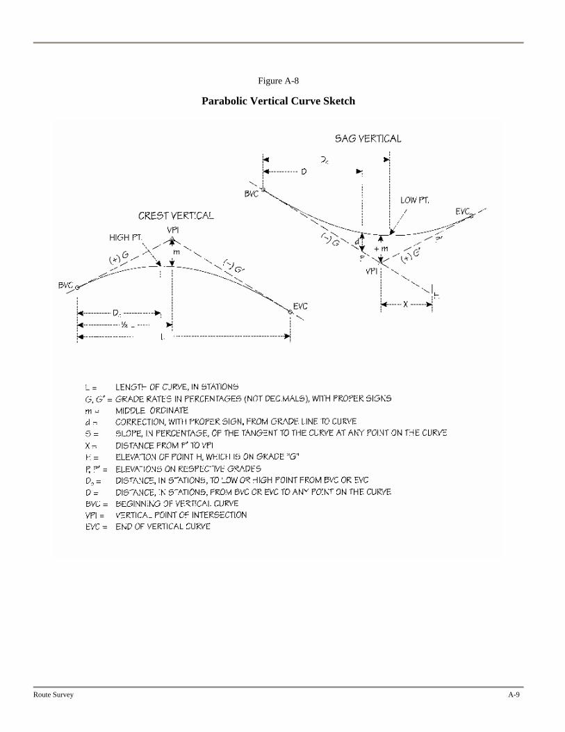
Figure A-8
Parabolic Vertical Curve Sketch
Route Survey A-9
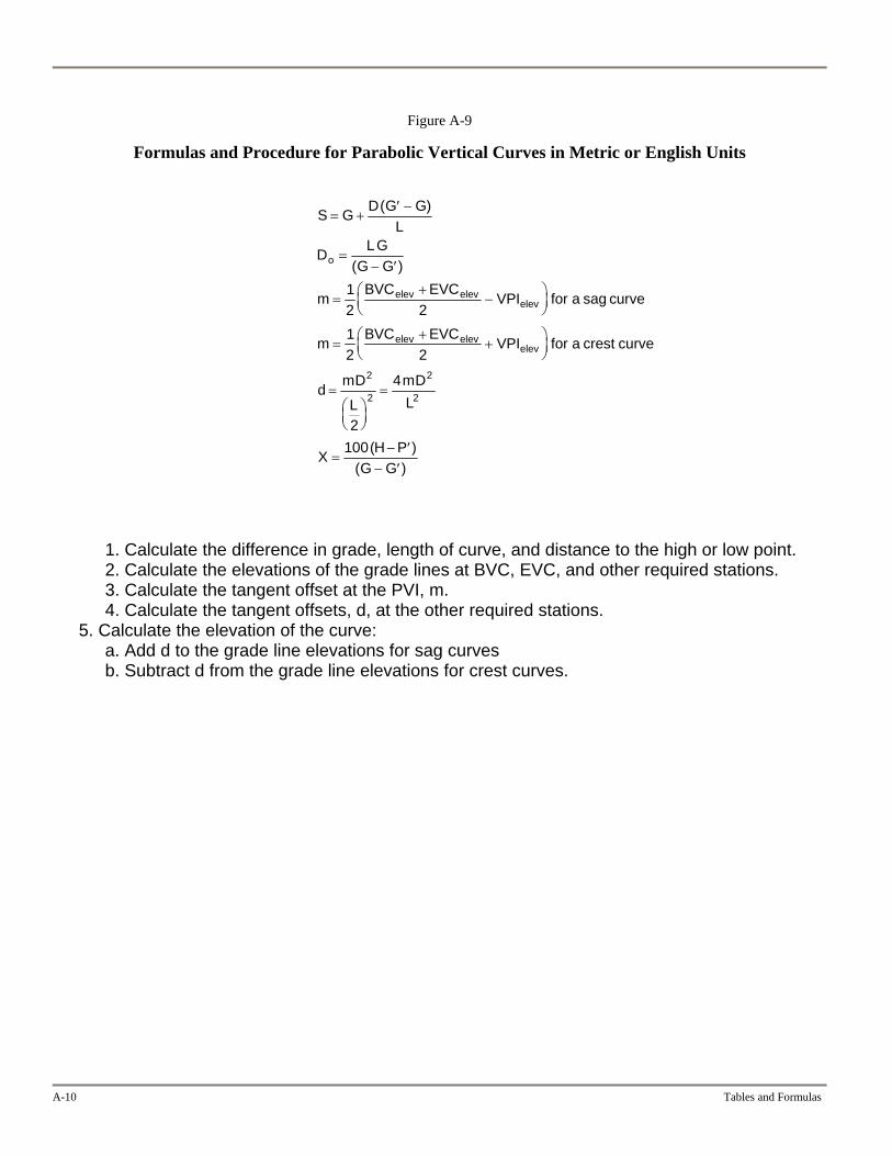
Figure A-9
Formulas and Procedure for Parabolic Vertical Curves in Metric or English Units
S G D G GL
D LGG G
m BVC EVC VPI for a sag curve
m BVC EVC VPI for a crest curve
d mD
L
mDL
X H PG G
o
elev elevelev
elev elevelev
= +′ −
=− ′
=+
−⎛⎝⎜
⎞⎠⎟
=+
+⎛⎝⎜
⎞⎠⎟
=⎛⎝⎜
⎞⎠⎟
=
=− ′
− ′
( )
( )
( )( )
12 212 2
2
4
100
2
2
2
2
1. Calculate the difference in grade, length of curve, and distance to the high or low point. 2. Calculate the elevations of the grade lines at BVC, EVC, and other required stations. 3. Calculate the tangent offset at the PVI, m. 4. Calculate the tangent offsets, d, at the other required stations.
5. Calculate the elevation of the curve: a. Add d to the grade line elevations for sag curves b. Subtract d from the grade line elevations for crest curves.
A-10 Tables and Formulas
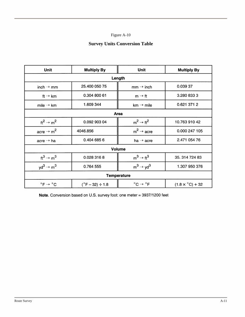
Figure A-10
Survey Units Conversion Table
Route Survey A-11
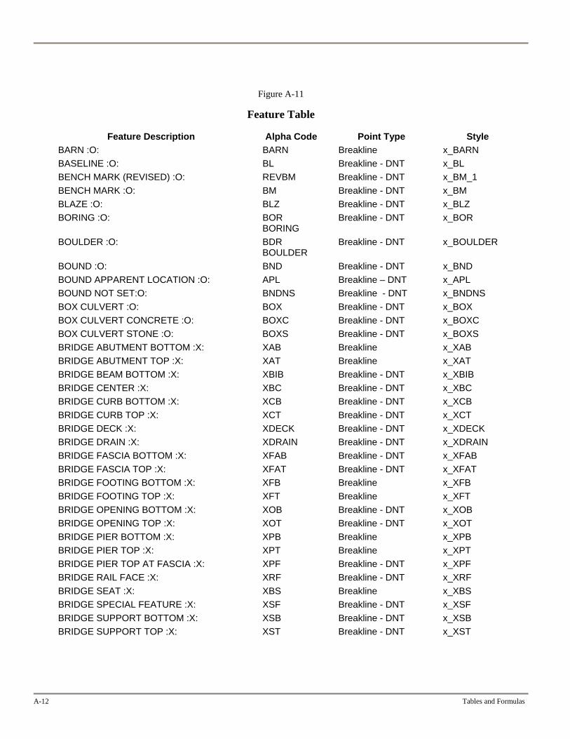
A-12 Tables and Formulas
Figure A-11
Feature Table
Feature Description Alpha Code Point Type Style BARN :O: BARN Breakline x_BARN BASELINE :O: BL Breakline - DNT x_BL BENCH MARK (REVISED) :O: REVBM Breakline - DNT x_BM_1 BENCH MARK :O: BM Breakline - DNT x_BM BLAZE :O: BLZ Breakline - DNT x_BLZ BORING :O: BOR
BORING Breakline - DNT x_BOR
BOULDER :O: BDR BOULDER
Breakline - DNT x_BOULDER
BOUND :O: BND Breakline - DNT x_BND BOUND APPARENT LOCATION :O: APL Breakline – DNT x_APL BOUND NOT SET:O: BNDNS Breakline - DNT x_BNDNS BOX CULVERT :O: BOX Breakline - DNT x_BOX BOX CULVERT CONCRETE :O: BOXC Breakline - DNT x_BOXC BOX CULVERT STONE :O: BOXS Breakline - DNT x_BOXS BRIDGE ABUTMENT BOTTOM :X: XAB Breakline x_XAB BRIDGE ABUTMENT TOP :X: XAT Breakline x_XAT BRIDGE BEAM BOTTOM :X: XBIB Breakline - DNT x_XBIB BRIDGE CENTER :X: XBC Breakline - DNT x_XBC BRIDGE CURB BOTTOM :X: XCB Breakline - DNT x_XCB BRIDGE CURB TOP :X: XCT Breakline - DNT x_XCT BRIDGE DECK :X: XDECK Breakline - DNT x_XDECK BRIDGE DRAIN :X: XDRAIN Breakline - DNT x_XDRAIN BRIDGE FASCIA BOTTOM :X: XFAB Breakline - DNT x_XFAB BRIDGE FASCIA TOP :X: XFAT Breakline - DNT x_XFAT BRIDGE FOOTING BOTTOM :X: XFB Breakline x_XFB BRIDGE FOOTING TOP :X: XFT Breakline x_XFT BRIDGE OPENING BOTTOM :X: XOB Breakline - DNT x_XOB BRIDGE OPENING TOP :X: XOT Breakline - DNT x_XOT BRIDGE PIER BOTTOM :X: XPB Breakline x_XPB BRIDGE PIER TOP :X: XPT Breakline x_XPT BRIDGE PIER TOP AT FASCIA :X: XPF Breakline - DNT x_XPF BRIDGE RAIL FACE :X: XRF Breakline - DNT x_XRF BRIDGE SEAT :X: XBS Breakline x_XBS BRIDGE SPECIAL FEATURE :X: XSF Breakline - DNT x_XSF BRIDGE SUPPORT BOTTOM :X: XSB Breakline - DNT x_XSB BRIDGE SUPPORT TOP :X: XST Breakline - DNT x_XST
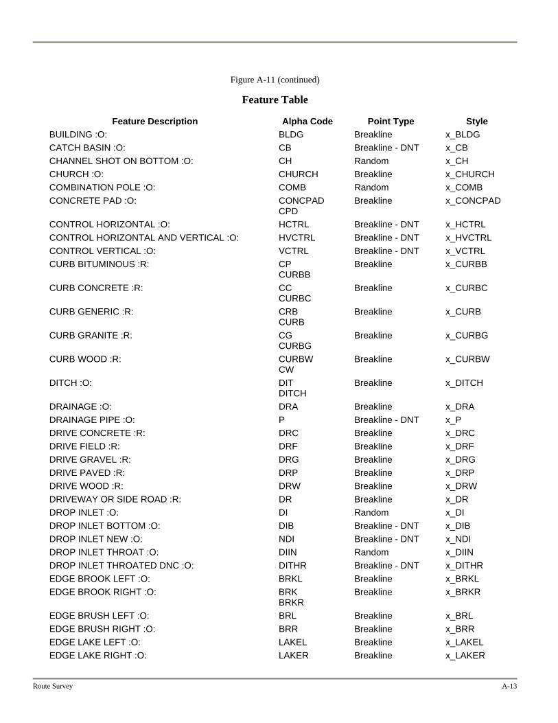
Route Survey A-13
Figure A-11 (continued)
Feature Table
Feature Description Alpha Code Point Type Style BUILDING :O: BLDG Breakline x_BLDG CATCH BASIN :O: CB Breakline - DNT x_CB CHANNEL SHOT ON BOTTOM :O: CH Random x_CH CHURCH :O: CHURCH Breakline x_CHURCH COMBINATION POLE :O: COMB Random x_COMB CONCRETE PAD :O: CONCPAD
CPD Breakline x_CONCPAD
CONTROL HORIZONTAL :O: HCTRL Breakline - DNT x_HCTRL CONTROL HORIZONTAL AND VERTICAL :O: HVCTRL Breakline - DNT x_HVCTRL CONTROL VERTICAL :O: VCTRL Breakline - DNT x_VCTRL CURB BITUMINOUS :R: CP
CURBB Breakline x_CURBB
CURB CONCRETE :R: CC CURBC
Breakline x_CURBC
CURB GENERIC :R: CRB CURB
Breakline x_CURB
CURB GRANITE :R: CG CURBG
Breakline x_CURBG
CURB WOOD :R: CURBW CW
Breakline x_CURBW
DITCH :O: DIT DITCH
Breakline x_DITCH
DRAINAGE :O: DRA Breakline x_DRA DRAINAGE PIPE :O: P Breakline - DNT x_P DRIVE CONCRETE :R: DRC Breakline x_DRC DRIVE FIELD :R: DRF Breakline x_DRF DRIVE GRAVEL :R: DRG Breakline x_DRG DRIVE PAVED :R: DRP Breakline x_DRP DRIVE WOOD :R: DRW Breakline x_DRW DRIVEWAY OR SIDE ROAD :R: DR Breakline x_DR DROP INLET :O: DI Random x_DI DROP INLET BOTTOM :O: DIB Breakline - DNT x_DIB DROP INLET NEW :O: NDI Breakline - DNT x_NDI DROP INLET THROAT :O: DIIN Random x_DIIN DROP INLET THROATED DNC :O: DITHR Breakline - DNT x_DITHR EDGE BROOK LEFT :O: BRKL Breakline x_BRKL EDGE BROOK RIGHT :O: BRK
BRKR Breakline x_BRKR
EDGE BRUSH LEFT :O: BRL Breakline x_BRL EDGE BRUSH RIGHT :O: BRR Breakline x_BRR EDGE LAKE LEFT :O: LAKEL Breakline x_LAKEL EDGE LAKE RIGHT :O: LAKER Breakline x_LAKER
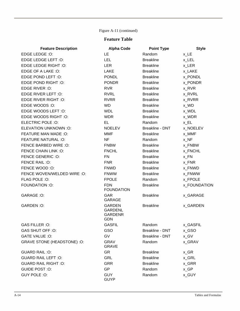
A-14 Tables and Formulas
Figure A-11 (continued)
Feature Table
Feature Description Alpha Code Point Type Style EDGE LEDGE :O: LE Random x_LE EDGE LEDGE LEFT :O: LEL Breakline x_LEL EDGE LEDGE RIGHT :O: LER Breakline x_LER EDGE OF A LAKE :O: LAKE Breakline x_LAKE EDGE POND LEFT :O: PONDL Breakline x_PONDL EDGE POND RIGHT :O: PONDR Breakline x_PONDR EDGE RIVER :O: RVR Breakline x_RVR EDGE RIVER LEFT :O: RVRL Breakline x_RVRL EDGE RIVER RIGHT :O: RVRR Breakline x_RVRR EDGE WOODS :O: WD Breakline x_WD EDGE WOODS LEFT :O: WDL Breakline x_WDL EDGE WOODS RIGHT :O: WDR Breakline x_WDR ELECTRIC POLE :O: EL Random x_EL ELEVATION UNKNOWN :O: NOELEV Breakline - DNT x_NOELEV FEATURE MAN MADE :O: MMF Breakline x_MMF FEATURE NATURAL :O: NF Random x_NF FENCE BARBED WIRE :O: FNBW Breakline x_FNBW FENCE CHAIN LINK :O: FNCHL Breakline x_FNCHL FENCE GENERIC :O: FN Breakline x_FN FENCE RAIL :O: FNR Breakline x_FNR FENCE WOOD :O: FNWD Breakline x_FNWD FENCE WOVEN/WELDED WIRE :O: FNWW Breakline x_FNWW FLAG POLE :O: FPOLE Random x_FPOLE FOUNDATION :O: FDN
FOUNDATION Breakline x_FOUNDATION
GARAGE :O: GAR GARAGE
Breakline x_GARAGE
GARDEN :O: GARDEN GARDENL GARDENR GDN
Breakline x_GARDEN
GAS FILLER :O: GASFIL Random x_GASFIL GAS SHUT OFF :O: GSO Breakline - DNT x_GSO GATE VALUE :O: GV Breakline - DNT x_GV GRAVE STONE (HEADSTONE) :O: GRAV
GRAVE Random x_GRAV
GUARD RAIL :O: GR Breakline x_GR GUARD RAIL LEFT :O: GRL Breakline x_GRL GUARD RAIL RIGHT :O: GRR Breakline x_GRR GUIDE POST :O: GP Random x_GP GUY POLE :O: GUY
GUYP Random x_GUY
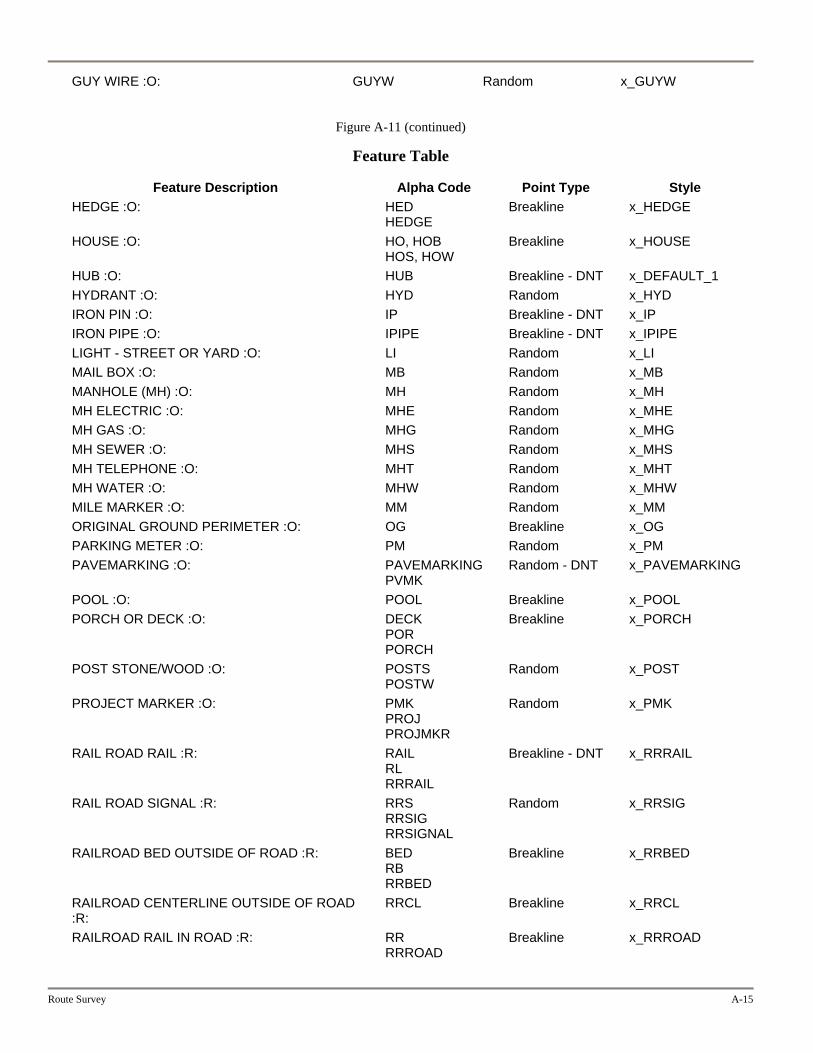
Route Survey A-15
GUY WIRE :O: GUYW Random x_GUYW
Figure A-11 (continued)
Feature Table
Feature Description Alpha Code Point Type Style HEDGE :O: HED
HEDGE Breakline x_HEDGE
HOUSE :O: HO, HOB HOS, HOW
Breakline x_HOUSE
HUB :O: HUB Breakline - DNT x_DEFAULT_1 HYDRANT :O: HYD Random x_HYD IRON PIN :O: IP Breakline - DNT x_IP IRON PIPE :O: IPIPE Breakline - DNT x_IPIPE LIGHT - STREET OR YARD :O: LI Random x_LI MAIL BOX :O: MB Random x_MB MANHOLE (MH) :O: MH Random x_MH MH ELECTRIC :O: MHE Random x_MHE MH GAS :O: MHG Random x_MHG MH SEWER :O: MHS Random x_MHS MH TELEPHONE :O: MHT Random x_MHT MH WATER :O: MHW Random x_MHW MILE MARKER :O: MM Random x_MM ORIGINAL GROUND PERIMETER :O: OG Breakline x_OG PARKING METER :O: PM Random x_PM PAVEMARKING :O: PAVEMARKING
PVMK Random - DNT x_PAVEMARKING
POOL :O: POOL Breakline x_POOL PORCH OR DECK :O: DECK
POR PORCH
Breakline x_PORCH
POST STONE/WOOD :O: POSTS POSTW
Random x_POST
PROJECT MARKER :O: PMK PROJ PROJMKR
Random x_PMK
RAIL ROAD RAIL :R: RAIL RL RRRAIL
Breakline - DNT x_RRRAIL
RAIL ROAD SIGNAL :R: RRS RRSIG RRSIGNAL
Random x_RRSIG
RAILROAD BED OUTSIDE OF ROAD :R: BED RB RRBED
Breakline x_RRBED
RAILROAD CENTERLINE OUTSIDE OF ROAD :R:
RRCL Breakline x_RRCL
RAILROAD RAIL IN ROAD :R: RR RRROAD
Breakline x_RRROAD
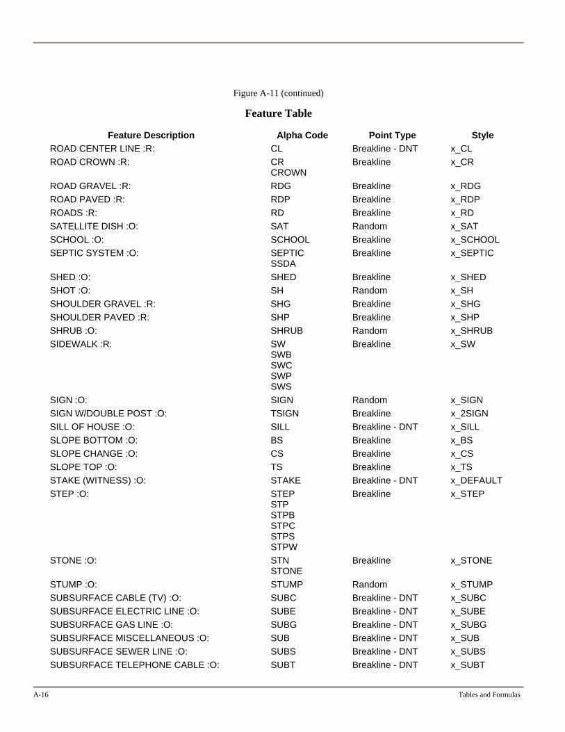
A-16 Tables and Formulas
Figure A-11 (continued)
Feature Table
Feature Description Alpha Code Point Type Style ROAD CENTER LINE :R: CL Breakline - DNT x_CL ROAD CROWN :R: CR
CROWN Breakline x_CR
ROAD GRAVEL :R: RDG Breakline x_RDG ROAD PAVED :R: RDP Breakline x_RDP ROADS :R: RD Breakline x_RD SATELLITE DISH :O: SAT Random x_SAT SCHOOL :O: SCHOOL Breakline x_SCHOOL SEPTIC SYSTEM :O: SEPTIC
SSDA Breakline x_SEPTIC
SHED :O: SHED Breakline x_SHED SHOT :O: SH Random x_SH SHOULDER GRAVEL :R: SHG Breakline x_SHG SHOULDER PAVED :R: SHP Breakline x_SHP SHRUB :O: SHRUB Random x_SHRUB SIDEWALK :R: SW
SWB SWC SWP SWS
Breakline x_SW
SIGN :O: SIGN Random x_SIGN SIGN W/DOUBLE POST :O: TSIGN Breakline x_2SIGN SILL OF HOUSE :O: SILL Breakline - DNT x_SILL SLOPE BOTTOM :O: BS Breakline x_BS SLOPE CHANGE :O: CS Breakline x_CS SLOPE TOP :O: TS Breakline x_TS STAKE (WITNESS) :O: STAKE Breakline - DNT x_DEFAULT STEP :O: STEP
STP STPB STPC STPS STPW
Breakline x_STEP
STONE :O: STN STONE
Breakline x_STONE
STUMP :O: STUMP Random x_STUMP SUBSURFACE CABLE (TV) :O: SUBC Breakline - DNT x_SUBC SUBSURFACE ELECTRIC LINE :O: SUBE Breakline - DNT x_SUBE SUBSURFACE GAS LINE :O: SUBG Breakline - DNT x_SUBG SUBSURFACE MISCELLANEOUS :O: SUB Breakline - DNT x_SUB SUBSURFACE SEWER LINE :O: SUBS Breakline - DNT x_SUBS SUBSURFACE TELEPHONE CABLE :O: SUBT Breakline - DNT x_SUBT
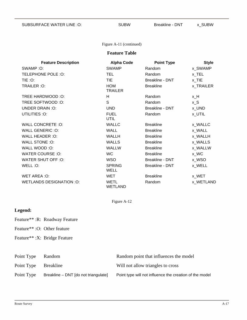
Route Survey A-17
SUBSURFACE WATER LINE :O: SUBW Breakline - DNT x_SUBW
Figure A-11 (continued)
Feature Table
Feature Description Alpha Code Point Type Style SWAMP :O: SWAMP Random x_SWAMP TELEPHONE POLE :O: TEL Random x_TEL TIE :O: TIE Breakline - DNT x_TIE TRAILER :O: HOM
TRAILER Breakline x_TRAILER
TREE HARDWOOD :O: H Random x_H TREE SOFTWOOD :O: S Random x_S UNDER DRAIN :O: UND Breakline - DNT x_UND UTILITIES :O: FUEL
UTIL Random x_UTIL
WALL CONCRETE :O: WALLC Breakline x_WALLC WALL GENERIC :O: WALL Breakline x_WALL WALL HEADER :O: WALLH Breakline x_WALLH WALL STONE :O: WALLS Breakline x_WALLS WALL WOOD :O: WALLW Breakline x_WALLW WATER COURSE :O: WC Breakline x_WC WATER SHUT OFF :O: WSO Breakline - DNT x_WSO WELL :O: SPRING
WELL Breakline - DNT x_WELL
WET AREA :O: WET Breakline x_WET WETLANDS DESIGNATION :O: WETL
WETLAND Random x_WETLAND
Figure A-12
Legend:
Feature** :R: Roadway Feature
Feature** :O: Other feature
Feature** :X: Bridge Feature
Point Type Random Random point that influences the model
Point Type Breakline Will not allow triangles to cross
Point Type Breakline – DNT [do not triangulate] Point type will not influence the creation of the model


Appendix B
Vermont Coordinate System
Route Survey B-1
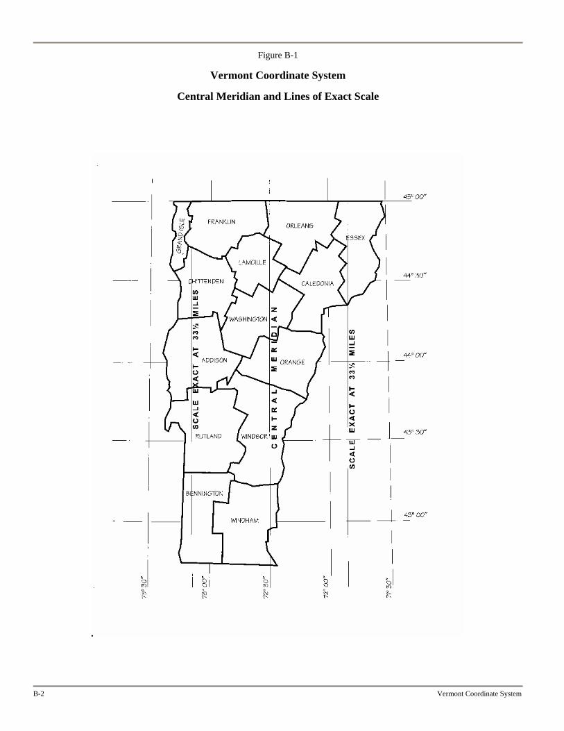
Figure B-1
Vermont Coordinate System
Central Meridian and Lines of Exact Scale
B-2 Vermont Coordinate System
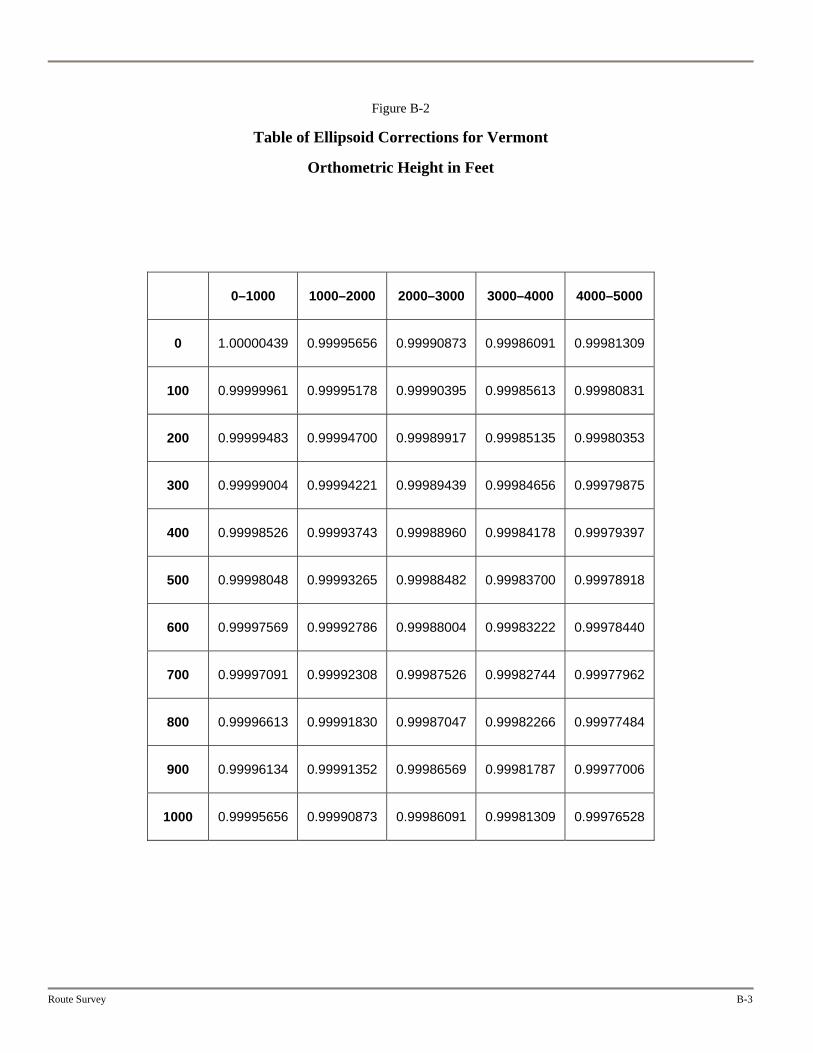
Figure B-2
Table of Ellipsoid Corrections for Vermont
Orthometric Height in Feet
0–1000 1000–2000 2000–3000 3000–4000 4000–5000
0 1.00000439 0.99995656 0.99990873 0.99986091 0.99981309
100 0.99999961 0.99995178 0.99990395 0.99985613 0.99980831
200 0.99999483 0.99994700 0.99989917 0.99985135 0.99980353
300 0.99999004 0.99994221 0.99989439 0.99984656 0.99979875
400 0.99998526 0.99993743 0.99988960 0.99984178 0.99979397
500 0.99998048 0.99993265 0.99988482 0.99983700 0.99978918
600 0.99997569 0.99992786 0.99988004 0.99983222 0.99978440
700 0.99997091 0.99992308 0.99987526 0.99982744 0.99977962
800 0.99996613 0.99991830 0.99987047 0.99982266 0.99977484
900 0.99996134 0.99991352 0.99986569 0.99981787 0.99977006
1000 0.99995656 0.99990873 0.99986091 0.99981309 0.99976528
Route Survey B-3
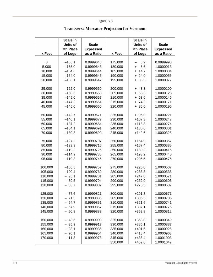
Figure B-3
Transverse Mercator Projection for Vermont
Scale in Scale in Units of Scale Units of Scale 7th Place Expressed 7th Place Expressed
x Feet of Logs as a Ratio x Feet of Logs as a Ratio 0 –155.1 0.9999643 175,000 –003.2 0.9999993
5,000 –155.0 0.9999643 180,000 +005.6 1.0000013 10,000 –154.6 0.9999644 185,000 +014.7 1.0000034 15,000 –154.0 0.9999645 190,000 +024.0 1.0000055 20,000 –153.1 0.9999647 195,000 +033.5 1.0000077
25,000 –152.0 0.9999650 200,000 +043.3 1.0000100 30,000 –150.6 0.9999653 205,000 +053.3 1.0000123 35,000 –149.0 0.9999657 210,000 +063.6 1.0000146 40,000 –147.2 0.9999661 215,000 +074.2 1.0000171 45,000 –145.0 0.9999666 220,000 +085.0 1.0000196
50,000 –142.7 0.9999671 225,000 +096.0 1.0000221 55,000 –140.1 0.9999677 230,000 +107.3 1.0000247 60,000 –137.2 0.9999684 235,000 +118.8 1.0000274 65,000 –134.1 0.9999691 240,000 +130.6 1.0000301 70,000 –130.8 0.9999699 245,000 +142.6 1.0000328
75,000 –127.2 0.9999707 250,000 +154.9 1.0000357 80,000 –123.3 0.9999716 255,000 +167.4 1.0000385 85,000 –119.2 0.9999726 260,000 +180.2 1.0000415 90,000 –114.9 0.9999735 265,000 +193.2 1.0000445 95,000 –110.3 0.9999746 270,000 +206.5 1.0000475
100,000 –105.5 0.9999757 275,000 +220.0 1.0000507 105,000 –100.4 0.9999769 280,000 +233.8 1.0000538 110,000 – 95.1 0.9999781 285,000 +247.8 1.0000571 115,000 – 89.5 0.9999794 290,000 +262.0 1.0000603 120,000 – 83.7 0.9999807 295,000 +276.5 1.0000637
125,000 – 77.6 0.9999821 300,000 +291.3 1.0000671 130,000 – 71.3 0.9999836 305,000 +306.3 1.0000705 135,000 – 64.7 0.9999851 310,000 +321.6 1.0000741 140,000 – 57.9 0.9999867 315,000 +337.1 1.0000776 145,000 – 50.8 0.9999883 320,000 +352.8 1.0000812
150,000 – 43.5 0.9999900 325,000 +368.8 1.0000849 155,000 – 35.9 0.9999917 330,000 +385.1 1.0000887 160,000 – 28.1 0.9999935 335,000 +401.6 1.0000925 165,000 – 20.1 0.9999954 340,000 +418.4 1.0000963 170,000 – 11.8 0.9999973 345,000 +435.4 1.0001003
350,000 +452.6 1.0001042
B-4 Vermont Coordinate System
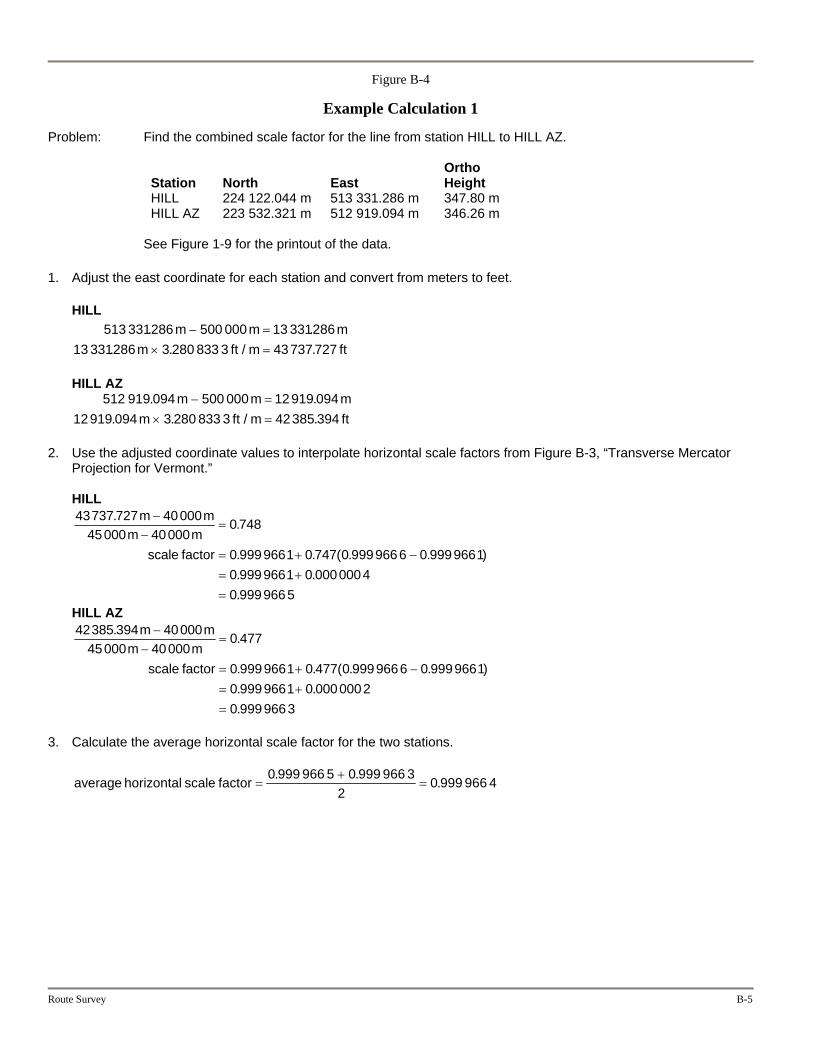
Figure B-4
Example Calculation 1
Problem: Find the combined scale factor for the line from station HILL to HILL AZ.
Station
North
East
Ortho Height
HILL 224 122.044 m 513 331.286 m 347.80 m HILL AZ 223 532.321 m 512 919.094 m 346.26 m
See Figure 1-9 for the printout of the data. 1. Adjust the east coordinate for each station and convert from meters to feet.
HILL
Route Survey B-5
mft
mft
513 331286 500 000 13 33128613 331286 3 280 833 3 43737 727
. .. . / .
m mm ft m
− =× =
HILL AZ
512 919 094 500 000 12919 094
12919 094 3 280 833 3 42385 394. .
. . / .m m
m ft m− =
× = 2. Use the adjusted coordinate values to interpolate horizontal scale factors from Figure B-3, “Transverse Mercator
Projection for Vermont.” HILL
43737 727 4000045000 40000
0 748
0 9999661 0 747 0 9999666 0 99996610 9999661 0 00000040 9999665
. .
. . ( . .
. .
.
m mm m
scale factor
−−
=
= + −= +=
)
HILL AZ 42385 394 40000
45000 400000 477
0 9999661 0 477 0 9999666 0 99996610 9999661 0 00000020 9999663
. .
. . ( . .
. .
.
m mm m
scale factor
−−
=
= + −= +=
)
3. Calculate the average horizontal scale factor for the two stations.
average horizontal scale factor = +=
0 999 966 5 0 999 966 32
0 999 966 4. . .
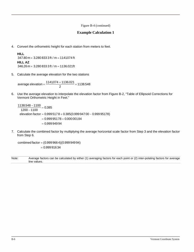
Figure B-4 (continued)
Example Calculation 1
4. Convert the orthometric height for each station from meters to feet.
B-6 Vermont Coordinate System
ft
ft
HILL 347 80 3 280 833 3 1141074. . / .m ft m× = HILL AZ 346 26 3 280 833 3 1136 021. . / .m ft m× =
5. Calculate the average elevation for the two stations
average elevation =+
=1141074 1136 021
21138 548. . .
6. Use the average elevation to interpolate the elevation factor from Figure B-2, “Table of Ellipsoid Corrections for
Vermont Orthometric Height in Feet.”
1138 548 11001200 1100
0 385
0 9995178 0 385 0 99994700 0 999951780 99995178 0 000001840 99994994
. .
. . ( . .
. .
.
−−
=
= + −= +=
elevation factor )
7. Calculate the combined factor by multiplying the average horizontal scale factor from Step 3 and the elevation factor
from Step 6.
combined factor ==
( . )( . ).0 9999664 0 99994994
0 99991634
Note: Average factors can be calculated by either (1) averaging factors for each point or (2) inter-polating factors for average line values.
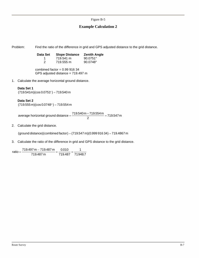
Figure B-5
Example Calculation 2
Problem: Find the ratio of the difference in grid and GPS adjusted distance to the grid distance.
Data Set Slope Distance Zenith Angle 1 719.541 m 90.0751° 2 719.555 m 90.0748°
combined factor = 0.99 916 34 GPS adjusted distance = 719.497 m
1. Calculate the average horizontal ground distance. Data Set 1
( . )(cos . ) .719 541 0 0751 719 540m m° = Data Set 2 ( . )(cos . ) .719 555 0 0748 719 554m m° =
average horizontal ground distance =+
=719 540 719 554
2719 547. . .m m m
2. Calculate the grid distance.
( )( ) ( . )( . ) .ground combined factor m mdistance = =719 547 0 999 916 34 719 4867
3. Calculate the ratio of the difference in grid and GPS distance to the grid distance.
ratiom m
m=
−= =
719 497 719 487719 487
0 010719 487
171948 7
. ..
.. .
Route Survey B-7
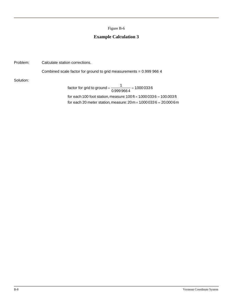
Figure B-6
Example Calculation 3
Problem: Calculate station corrections. Combined scale factor for ground to grid measurements = 0.999 966 4 Solution:
factor for grid to ground
for each foot station measure ft ftfor each meter station measure m m
= =
× =× =
10 9999664
10000336
100 100 10000336 100 00320 20 10000336 20 0006
..
, : . ., : . .
B-8 Vermont Coordinate System
Appendix C
Boundaries
A land surveyor who conducts a survey of property (for the AOT) shall set monuments when needed to adequately perpetuate the location of corners and boundaries of the property being surveyed.
The monuments shall be durable and stable.
The monuments shall be identified with the license number of the surveyor in responsible charge.
Monuments that replace inadequate monuments shall conform to the minimum standard as defined by 26VSA Section 2502.
The setting of monuments shall meet the minimum standard for setting monuments by a land surveyor licensed by the State of Vermont.
See Figures C-1 and C-2 for marker and monument specifications.
Route Survey C-1
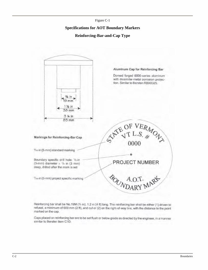
Figure C-1
Specifications for AOT Boundary Markers
Reinforcing-Bar-and-Cap Type
C-2 Boundaries
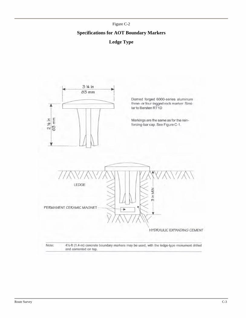
Figure C-2
Specifications for AOT Boundary Markers
Ledge Type
Route Survey C-3

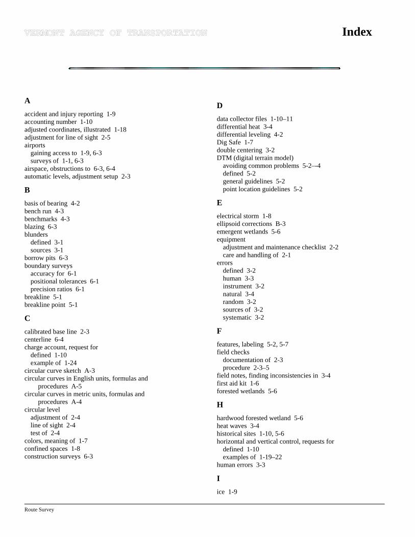
Index
A accident and injury reporting 1-9 accounting number 1-10 adjusted coordinates, illustrated 1-18 adjustment for line of sight 2-5 airports
gaining access to 1-9, 6-3 surveys of 1-1, 6-3
airspace, obstructions to 6-3, 6-4 automatic levels, adjustment setup 2-3
B basis of bearing 4-2 bench run 4-3 benchmarks 4-3 blazing 6-3 blunders
defined 3-1 sources 3-1
borrow pits 6-3 boundary surveys
accuracy for 6-1 positional tolerances 6-1 precision ratios 6-1
breakline 5-1 breakline point 5-1
C calibrated base line 2-3 centerline 6-4 charge account, request for
defined 1-10 example of 1-24
circular curve sketch A-3 circular curves in English units, formulas and
procedures A-5 circular curves in metric units, formulas and
procedures A-4 circular level
adjustment of 2-4 line of sight 2-4 test of 2-4
colors, meaning of 1-7 confined spaces 1-8 construction surveys 6-3
D data collector files 1-10–11 differential heat 3-4 differential leveling 4-2 Dig Safe 1-7 double centering 3-2 DTM (digital terrain model)
avoiding common problems 5-2–-4 defined 5-2 general guidelines 5-2 point location guidelines 5-2
E electrical storm 1-8 ellipsoid corrections B-3 emergent wetlands 5-6 equipment
adjustment and maintenance checklist 2-2 care and handling of 2-1
errors defined 3-2 human 3-3 instrument 3-2 natural 3-4 random 3-2 sources of 3-2 systematic 3-2
F features, labeling 5-2, 5-7 field checks
documentation of 2-3 procedure 2-3–5
field notes, finding inconsistencies in 3-4 first aid kit 1-6 forested wetlands 5-6
H hardwood forested wetland 5-6 heat waves 3-4 historical sites 1-10, 5-6 horizontal and vertical control, requests for
defined 1-10 examples of 1-19–22
human errors 3-3
I ice 1-9
Route Survey
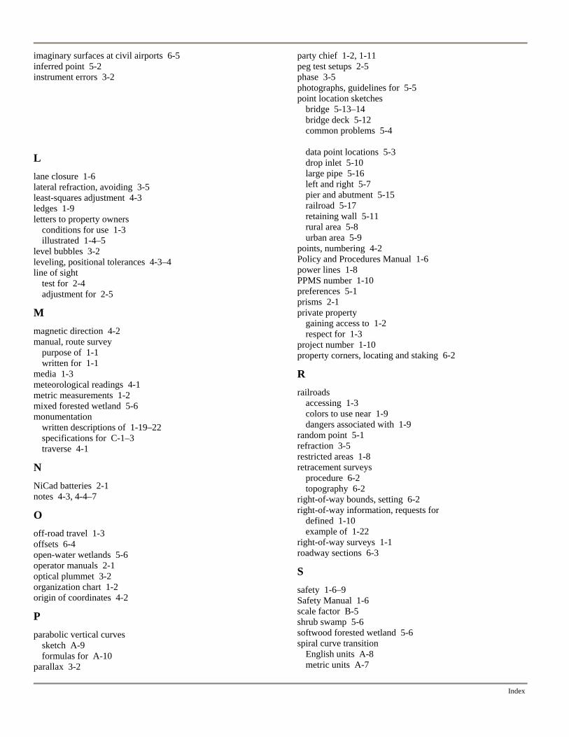
Index
imaginary surfaces at civil airports 6-5 inferred point 5-2 instrument errors 3-2
L lane closure 1-6 lateral refraction, avoiding 3-5 least-squares adjustment 4-3 ledges 1-9 letters to property owners
conditions for use 1-3 illustrated 1-4–5
level bubbles 3-2 leveling, positional tolerances 4-3–4 line of sight
test for 2-4 adjustment for 2-5
M magnetic direction 4-2 manual, route survey
purpose of 1-1 written for 1-1
media 1-3 meteorological readings 4-1 metric measurements 1-2 mixed forested wetland 5-6 monumentation
written descriptions of 1-19–22 specifications for C-1–3 traverse 4-1
N NiCad batteries 2-1 notes 4-3, 4-4–7
O off-road travel 1-3 offsets 6-4 open-water wetlands 5-6 operator manuals 2-1 optical plummet 3-2 organization chart 1-2 origin of coordinates 4-2
P parabolic vertical curves
sketch A-9 formulas for A-10
parallax 3-2
party chief 1-2, 1-11 peg test setups 2-5 phase 3-5 photographs, guidelines for 5-5 point location sketches
bridge 5-13–14 bridge deck 5-12 common problems 5-4
data point locations 5-3 drop inlet 5-10 large pipe 5-16 left and right 5-7 pier and abutment 5-15 railroad 5-17 retaining wall 5-11 rural area 5-8 urban area 5-9
points, numbering 4-2 Policy and Procedures Manual 1-6 power lines 1-8 PPMS number 1-10 preferences 5-1 prisms 2-1 private property
gaining access to 1-2 respect for 1-3
project number 1-10 property corners, locating and staking 6-2
R railroads
accessing 1-3 colors to use near 1-9 dangers associated with 1-9
random point 5-1 refraction 3-5 restricted areas 1-8 retracement surveys
procedure 6-2 topography 6-2
right-of-way bounds, setting 6-2 right-of-way information, requests for
defined 1-10 example of 1-22
right-of-way surveys 1-1 roadway sections 6-3
S safety 1-6–9 Safety Manual 1-6 scale factor B-5 shrub swamp 5-6 softwood forested wetland 5-6 spiral curve transition
English units A-8 metric units A-7

Route Survey
sketch A-6 state plane grid B-2 subsurface features 5-5 survey classification definitions 6-2 survey computer technician 1-2 survey crew
composition of 1-2 damage caused by 1-3
survey crew report
instructions for completing 1-11 example of 1-26
survey files, processing of 1-10 survey, requests for
defined 1-10 examples of 1-12–16 reply to
description 1-10 example of 1-24
special requirements 1-2 survey technician 1-2 survey transfer
defined 1-11 example of 1-25
survey units conversion table A-11
T ties 4-2 tools, proper use of 1-6–7 topography
accuracy 5-1 definitions 5-1 preferences 5-1
total station calibration base lines 2-3 field checks 2-3 use of 2-2
town map 1-10, 1-14 transverse Mercator projection B-4 traverse
accuracy 4-1 adjustments 4-2 configuration 4-1 monumentation 4-1
trees, cutting and trimming 1-3 trigonometric formulas A-2 trigonometric leveling 4-2 typical work 1-1
V vehicles
privately owned 1-6 state owned 1-6
W water 1-9 wet meadows 5-6
wetlands 5-6 wooded areas 1-8 Worksite Traffic Control Manual 1-6