Embed Size (px)
Citation preview

EK-RL012-PG-003
RL01/RL02 POCKET SERVICE GUIDE
digital equipment corporation colorado springs, colorado
I st Edition, September 1979 (Revision) June 1980
(2nd Revision) October 1980
Copyright ©' I 979, 1980 by Digital Equipment Corporation
The material in this manual is for informational purposes and is subject to change without notice.
Digital Equipment Corporation assumes no responsibility for any errors which may appear in this manual.
Printed in U.S.A.
The following are trademarks of Digital Equipment Corporation, Maynard, Massachusetts:
DEC DECsystem-10 DIBOL lAS OMNIBUS Q-BUS UNIBUS
DECUS DECSYSTEM-20 Digital Logo LSI-11 PDP RSTS VAX VT
DECnet DECwriter EduSystem MASSBUS PDT RSX VMS

CONTENTS
1 INTRODUCTION . .................. .
1. 1 Description .............................. . 1.2 Option Descriptions ........................ 3 1. 3 Sector Format . . . . . . . . . . . . . . . . . . . . . . . . . . . .. 4 1.4 Bad Sector File. . . . . . . . . . . . . . . . . . . . . . . . . . .. 4
2 FIELD REPLACEABLE UNITS ....... 7
3 FRONT PANEL .................... 21
4 DRIVE CONDITIONS . .............. 23
5 REGISTER SUMMARY ............. 25
5.1 RLll/RL V11 Register Summary ............ 25 5.2 RLS-A Register Summary .................. 32
6 BOOTSTRAPS. . . . . . . . . . . . . . . . . . . .. 41
6.1 RLll/RL V 11 Bootstrap. . . . . . . . . . . . . . . . . . .. 41 6.2 RLS-A Bootstrap ......................... 41
7 TOGGLE·IN PROGRAMS . .......... 43
7.1 Head Selection Program for RLll/RLV11 ..... 43 7.2 Head Selection Program for RLS-A .......... 44 7.3 Get Status (With or Without Reset)
on an RL ll/RL V 11 Subsystem. . . . . . . . . . . . .. 44 7.4 Get Status on an RLS-A Subsystem .......... .45
7.5 Oscillating Seek for RLll/RLVll ........... 46. 7.6 Oscillating Seek for RLS-A ................. 47
iii

IV CONTENTS
8 DIAGNOSTICS. . . . . . . . . . . . . . . . . . . .. 49
8.1 RLI 1 Diagnostics ......................... 49 8.2 RLVII Diagnostics ....................... 50 8.3 RL8-A Diagnostics ........................ 50 8,4 Diagnostic Supervisor ..................... 50 8,4.1 Hardcore Questions ................... 50 8,4.2 Console Controls ..................... 53 8,4.3 Hardware Questions ................... 53 8,4,4 Software Question ................... 53
9 CHECKS, ADJUSTMENTS AND ALIGNMENTS ...................... 55
9.1 Introduction ........................... 55 9.2 Voltage Checks ......................... 56 9.3 Sector Transducer Output Check . . . . . . . .. 57 9,4 Sector Pulse Timing Check ............... 58 9.5 Positioner Radial Alignment .. . . . . . . . . . .. 58 9.6 Head Alignment ........................ 63 9.7 Read Signal Amplitude Check ............ 68 9.8 Spindle Runout Check .................. 69 9.9 Position Signal Gain Check .............. 71 9.10 Tachometer AC Noise Pick-Up Check ..... 72 9.11 Velocity Profile Check ................... 74 9.12 Servo Drive Motor Current Check ........ 75 9.13 Access Time Check ..................... 76
10 SERVICE TIPS ..................... 81
10.1 Loss of + 5V Symptom .................... 81 10.2 Loss of + 5V Causes ...................... 81 10.3 Heads Retract Immediately After Loading ..... 81 10,4 LOAD, READY, and FAULT Indicators
All On .................................. 81 10.5 RLI 1 I/O Cabling ........................ 81 10.6 Early RLI I/RLVI 1 Vector Assignment ....... 81 10.7 Role of Checks, Adjustments and
Alignments in Troubleshooting ............ 82 10.8 Intermittent Read Check Errors ........... 82

CONTENTS v
FIGURES
I-I Sector Format . . . . . . . . . . . . . . . . . . . . . . . . . . . .. 5 1-2 Bad Sector File ............................ 6 2-1 Interconnection of FRUs .................... 9 2-2 Signal and Function Diagram of Power
Panel, AC Servo, Brush Drive Assembly ..... \0 2-3 Signal. and Function Diagram of DC
Servo, Positioner ......................... 11 2-4 Signal and Function Diagram of R!W
Module, R!W Heads ...................... 12 2-5 Signal and Function Diagram of Front Panel. .. 13 2-6 Signal and Function Diagram of Drive
Logic Module ............................ 14 2-7 Physical Location of FRUs ................. 15 2-8 Rear View. . . . . . . . . . . . . . . . . . . . . . . . . . . . . .. 15 2-9 Drive Logic Module Layout ................ 17 2-10 R!W Module Layout - Top View. . . . . . . . . .. 18 2-11 Power Panel Layout - Front View . . . . . . . . .. 18 2-12 DC Servo Module Layout - Bottom View 19
2-13 AC Servo Module Layout - Front View ... 20 2-14 9-1 9-2 9-3
9-4 9-5 9-6 9-7 9-8 9-9 9-10 9-11 9-12 9-13 9-14
Front Panel Layout - Rear View ........ . Sector Transducer Output ................. . Sector Pulse Timing .................... . Positioner and Read I Write Module
20 57
59
Box Assembly .......................... 60 Servo Bursts and Sector Pulse ............ 61 Positioner Assembly ..................... 62 Adjusting the Head Cables ............... 67 Position Signal ......................... 70 Position Signal Gain Check Waveform 72 Summing Amplifier Output .............. 73 Tachometer Output Velocity Signal 75 Positioner Motor Current Check .......... 76 Access Time Check (One Track Seek) 77 Access Time Check (85 or 170 Track Seek) 78 Access Time Check (255 or 511 Track Seek) 79

VI CONTENTS
TABLES
I-I Voltage Ranges ........................... 2 2-1 FRU Part Numbers and Interchangeability ...... 7 2-2 Cables. . . . . . . . . . . . . . . . . . . . . . . . . . . . . . . . . .. 8 2-3 Test Points - Drive Logic Module
54-12175 (Version I) ...................... 16 2-4 Test Points - Drive Logic Module
54-13531 (Version 2) ...................... 16 2-5 Test Points - Drive Logic Module
54-14025 (Version 3) . . . . . . . . . . . . . . . . . . . . .. 16 4-1 Drive Conditions ......................... 23 5-1 Controller Addressable Registers ............ 25 5-2 RL8-A Instruction Set ..................... 32 8-1 RLlI/RLOI Diagnostics .................... 49 8-2 RLiI/RL02 Diagnostics .................... 49 8-3 RL8-A/RLOI Diagnostics .................. 50 8-4 RL8-A/RL02 Diagnostics .................. 50 9-1 Service Jumpers for Drive Logic Module ...... 55 9-2 Methods for Selecting Heads ............... 56
CHAPTER 1 INTRODUCTION
CHAPTER 2 FIELD REPLACEABLE UNITS
CHAPTER 3 FRONT PANEL
CHAPTER 4 DRIVE CONDITIONS
CHAPTER 5 REGISTER SUMMARY
CHAPTER 6 BOOTSTRAPS
CHAPTER 7 PROGRAMMING EXAMPLES
CHAPTER 8 DIAG NOSTICS
CHAPTER 9 CHECKS, ADJUSTMENTS AND
ALIGNMENTS
CHAPTER 10 SERVICE TIPS
vii

RL01/RL02 Disk Drive
The following RLOI/RL02 documents are in the microfiche library.
Name RLOI/RL02 Disk Drive
Technical Manual RLII Controller
Technical Description Manual RLVII Controller
Technical Manual RL8A Omnibus Controller
Technical Manual RLOI Disk Drive
Illustrated Parts Breakdown RL02 Disk Drive
Illustrated Parts Breakdown RLOI/RL02
Preventive Maintenance Procedures
Number
EP-RLOI2-TM
EP-ORLlI-TD
EP-RLVII-TD
EP-ORL8A-TM
EP-000l6-IP
EP-OOOI6-IP
EP-OOOO8-PM

CHAPTER 1 INTRODUCTION
1.1 DESCRIPTION An RLOI/RL02 Disk Subsystem consists of one to four RLOI or RL02 Disk Drives, daisy-chained via an va drive bus cable to one of three controllers. The controller may be an RL1I, RLVII or an RL8-A, depending upon the processor. The RL02 (using an RL02K-DC Cartridge) is the double density version of the RLOI (which uses an RLOIK-DC Cartridge). Below is a list of subsystem characteristics.
• Single platter, top-loading disk cartridge similar to the 5440 type (physically but not functionally)
• The RLOIK-DC and RL02K-DC cartridges are not functionally interchangeable but are physically interchangeable.
• RLOIK-DC=5.2 megabytes (formatted), RL02KDC= 10.4 megabytes
• RLOIK-DC=256 cylinders, RL02K-DC=512 cylinders • RLOIK-DC= 125 tracks/inch, RL02K-DC=250 tracks/
inch • Both platter surfaces are used for data (upper=O, low
er= I) • 40 sectors per track - hub notched for sector marks, no
index notch • 256 eight bit bytes per sector (128 16-bit words or 170
12-bit words) • Platter rotates at 2400 r/min - 25 ms/rev • 3725 bits/in - 147 bits/mm max bit density • 244 ns cell time - 4. I megabits/sec • MFM (Miller coding) recording technique • Peak transfer rate=3.9 /Ls/16-bit word, 1.9/Ls/8-bit byte,
2.9 /Ls/12-bit word • Average transfer rate=4.9 /Ls/16-bit word, 2.4 /Ls/8-bit
byte, 3.7 /Ls/12-bit word • Positioner control=track-following servo information im
bedded in data track during sector pulse time (servo information is read with data R!W head)
• Positioner type=D.C. servo motor with capstan/cable drive and tachometer feedback
• Factory-formatted servo and header information cannot be reformatted in the field

2 INTRODUCTION
• Seek to next cylinder = 17 ms (max) • Seek to next surface (switch heads) = 15 ms (max) • Above two operations combined = 17 ms (max) • Maximum seek= 100 ms • Average seek=55 ms • Average rotational latency = 12.5 ms • No hardware (implicit) seek • No hardware spiral (mid-transfer) seek • Seeks can be overlapped but subsystem gives no end of
seek interrupt • Sectors are staggered to optimize software spiral seeks • Automatic detection of inner, outer guard bands (unique
servo patterns) • Brush cycle on cartridge spin-up • Two separate air systems with heat exchanger
1) Open-air cooling system for modules with muffin fan and coarse filter
2) Closed-loop (recirculated) clean air system for cartridge using blower on spindle drive motor and absolute filter
• Spindle is belt driven from spindle drive/blower motor • Spindle speed feedback/correction loop compensates for
speed variations and allows for ac power frequency range of 50-60 Hz ± 5%
• Two reversible connectors allow for four ranges of ac power voltage (see Table 1-1)
Table 1-1 Voltage Ranges
Range 110/220
Connector
90-105 110 100-128 110 180-210 220 200-256 220
• No change for 50-60 Hz • RLII Controller for PDP-II UNIBUS
M7762 hex-height SPC module 16-bit word format Normal address=774400 Normal vector= 160 Normal interrupt level = BR5 Can handle RLOls and/or RL02s - can mix
LOW/NOM Connector
LOW NOM LOW NOM
Can handle up to four drives, and a total of 100 feet of daisy-chain drive bus

INTRODUCTION 3
• RLVll Controller for LSI-ll Q-Bus M8013 and M80l4 quad height modules l6-bit word format Normal address= 174400 Normal vector= 160 Interrupt level = standard (there is only one) Can handle RLOls and/or RL02s - can mix Can handle up to four drives, and a total of 100 feet of
daisy-chain drive bus .• RL8-A Controller for PDP-8 OMNIBUS
M8433 hex-height module 8-bit byte or 12-bit word format - program selectable l2-bit word mode = max transfer of one sector/
operation Normal device code = 60, 61 for fIrst controller, 62, 63
for second (if two controllers, only one can transfer data at a time)
Normal data break priority 0, can be jumpered for 1 Jumper selection of RLOI or RL02. If jumpered for
RL02, controller can handle either or both -can mix
Can.handle up to four drives, and a total of 100 feet of daisy-chain drive bus.
1.2 OPTION DESCRIPTIONS RLOlA=RLOl unit, BC20J-1O VO cable, chassis slide,
mounting hardware RL02A=RL02 unit, BC2OJ-1O VO cable, chassis slide,
mounting hardware RL01K-DC=RLOl Data Cartridge RL02K-DC=RL02 Data Cartridge RL01-AK=RLOIA, RL01K-DC RL02-AK=RL02A, RL02K-DC RL1l-AK=RL01-AK, RL1l, BC06R, transition connector,
terminator RL2ll-AK=RL02-AK, RL1l, BC06R, transition connec
tor, terminator RLV11-AK=RL01-AK, RLVll, BC06R, transition con
nector, terminator RLV2l-AK=RL02-AK, RLVll, BC06R, transition con
nector, terminator RL8A-AK=RL01-AK, RL8A, BC80J, terminator RL28A-AK=RL02-AK, RL8A, BC80J, terminator

4 INTRODUCTION
CABLE DESCRIPTIONS
BC06R-XX = Flat Berg to Berg. Used on RUI and RL V II subsystems to connect the controller module to a transition connector which converts Berg to ZIF.
BC20J-XX Round ZIF to ZIF I/O drive bus cable. Used to daisy chain one unit to another. Also used on RL 11 and RL V 11 subsystems to connect the transition connector to the fIrst unit. Can also be ordered as 70-12122-XX.
BC8OJ-XX Round Berg to ZIF cable used on RL8-A subsystems to connect the controller module to the fIrst unit.
Terminator = Required on last unit of a subsystem.
1.3 SECTOR FORMAT
See Figure 1-1. Each sector consists of:
• Servo data during the sector pulse time • Header preamble of 48 bits (47 zeroes followed by one
"1" marker bit) • First header information of 16 bits (this is the address and
indicates cylinder, surface, and sector) • Second header word of 16 zero bits • Third header word of 16 bits of CRC • Header postamble of 16 zero bits • Data preamble of 48 bits (47 zeros followed by one" I"
marker bit) • Data - 2048 bits (can be considered as 256 8-bit bytes or
128 16-bit word or 170 12-bit words with 8 unused bits) • Data CRC of 16 bits • Data postamble of 16 zero bits • Idle time waiting for next sector pulse. Varies but is
approximately 20 microseconds
The user-writable area starts with the data preamble and ends with the data postamble. The remainder is factory writable only.
1.4 BAD SECTOR FILE The Bad Sector File is located on the last track (last cylinder, last surface) of the cartridge. It occupies all forty sectors. The layout is illustrated in Figure 1-2.

: 825pa-----------...... , , ...............
~ :n I : : >O~r~----~---r----------------, 1 .. ~:~,o.1 HEADER I DATA I ~:~ I HEADER I DATA L //> -- - - , "<An._ ,<----> ----,
HEADER PREAMBLE
47 zeRO BITS
SECTOR
SIX BITS
.... ........
L-LSB r.,Ss-J
NAME MNEMONIC SERVO BURSTS SV HEADER PREAMBLE PAl HEADER HDR HEADER POSTAMBlE POl DATA PReAMBLE PR2 DATA DATA POSTAMBLE P02
Figure 1-1 Sector Format
LENGlli
3 WORDS 3 WORDS 1 WORD 3 WORDS 2048 BITS , WORD
DATA PREAMBLE DATA
47 ZERO BITS 2048 BITS
,.BlTmaRD I I ~mrROml MODE I' U 16 BITS 16 arTS
• ~~~ I::'::I--l-+' "I ... I ,.. I
tJlODE
LSB
~ ::c o o c ~ o z
U'1

LAST CYLINDER
LAST SURFACE
SEC TOR
0 1 2 3 4 5
7 8 9
" " 12
" 14 15 16 17
18 19 20
" 22 23 24 25 26 27 28 29 30 31 32 3J 34 35 36 37 38 39
BAD SECTOR FILE
CONTENTS
TWO FACTORY WRITTEN BAD seCTOR INFO SECTORS
ALL ONES 256 16 BIT
WORDS DUPLICATE OF SECTORS 0, 1
125
ALL ONES ENTRIES
DUPLICATE OF SECTORS 0, 1
ALL ONES
DUPLICATE OF SECTORS 0, 1
ALL ONES
DUPliCATE OF SECTORS 0, 1
ALL ONES
FIELD WRITTEN BAD SECTOR INFO
ALL ONES
DUPLICATE OF SECTORS 20, 21
ALL ONES
DUPLICATE Of SECTORS 20, 21
ALL ONES
DUPLICATE OF SECTORS 20, 21
ALL ONES
DUPLICATE OF SECTORS 20, 21
ALL ONES
9
MS.
~ OR 15
0 ZERO
1 ZERO
2
3
-.~! 4 SECTOR ENTRY 5
SECOND
~ BAD SECTOR ENTRY 7
1251h BAO { 252 SECTOR -ENTRY 253
254
255
16 BIT WORD LS.
14 I" 112 I " I" I 9 I • I 7 I 6 I 5 I 4 I 3 I 2 I 1 I 0
5 lEAST SIGNIFICANT OCTAL DIGITS OF CARTRIDGE SERIAL NUMBER
5 MOST SIGNIFICANT OCTAL DIGITS OF CARTRIDGE SERIAL NUMBER
ZEROS
ZEROS
ZEROS I CYLINDER ADDRESS
ZEROS IHEAOI ZEROS I SECTOR ADDRESS
SAME FORMAT AS FIRST BAD SECTOR ENTRY
SAME FORMAT AS FIRST BAD seCTOR ENTRY
ALL ONES
ALL ONES
e
J
1 !
O'l
z ~ o o c ~ o z
CHAPTER 2 FIELD REPLACEABLE UNITS
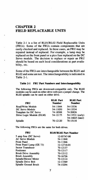
Table 2-1 is a list of RLOI/RL02 Field Replaceable Units (FRUs). Some of the FRUs contain components that are easily checked and replaced. In these cases, an FRU may be repaired insteliP of replaced. For example, a lamp may be replaced on the front panel or a pico fuse replaced on the DC Servo module. The decision to replace or repair an FRU should be based on such local considerations as part availability, etc.
Some of the FR Us are interchangeable between the RLO 1 and RL02 and some are not. The interchangeability is indicated in Table 2-1.
Table 2-1 FRU Part Numbers and IotercbangeabHity
The following FRUs are downward-compatible only. The RL02 modules can be used on either drive with just a jumper change. The RL02 spindle can be used on either drive.
FRU
Read/Write Module DC Servo Module Template for DC Servo Drive Logic Module (DLM)
Spindle
RLOI Part Number
54-11844 54-11850 74-18588 54-12175
70-12120
RL02Part Number
54-13536 54-13534 74-20826 54-13531 (early) 54-14025 (later) 70-15116
The following FRUs are the same for both drives.
FRU
5 amp fuse (DC Servo) AC Servo Module Front Panel Front Panel Lamp (GE 73) Sector Transducer Positioner Brush Drive Assembly Brush Assembly Spindle/Blower Motor Spindle Drive Belt Spindle Ground Brush
RLOI1RL02 Part Number
12-05747-00 54-11848
7
54-11846 12-12716-01 70-12137 70-12117 70-12112 70-16726 70-12114 12-13369 74-15294

8 FIELD REPLACEABLE UNITS
FRU
Head Cable Guide Insulating Sticker Coarse Filter Absolute Filter I/O Terminator Power Panel
• Terminator Block (voltage selection)
• Circuit Breaker • Line Filter • Rectifier • Transformer • Cap, 66,000 p.F
for + Vunreg • Cap, 20,000 p.F
for - Vunreg • Cap, for
RLOI/RL02 Part Number
70-16983 74-22834 74-15297 12-13097-03 70-12293-00 70-12130
74-16852-0IA 12-14360-02 12-12877-00 11-10051-00 16-13897-00
10-13530-00
10-13531-00
spindle motor 10-13102-00 • Fan 12-09403-01
The following FRUs are not interchangeable between an RLOI and an RL02.
RLOI Part RL02 Part FRU Number Number
Upper Head 74-17178-01. 70-15637-01 Lower Head 74-17178-00 70-15637-00
Table 2-2 lists the cables used in the subsystem.
Cable Deserlption Controller (RL II or
RLVI1) to transition connector
Controller (RL8-A) to frrst drive
I/O drive cable Front panel to DLM I/O coonector to DLM
AC Servo to DLM
Above two cables
Table 2-2 Cables
Part Number Comments
BC06R-IO
BC8OJ-20 BC2OJ-XX Also 70-12122-XX 70-12107 70-12123-0H Stocked as part of
70-14262-00 70-12139-0M Stocked as part of
70-14262-00
~sembled together 70-14262-00· Normally stocked DC Servo to DLM 70-12139-0F Signal cable DC Servo to DLM 70-12140 Power cable R/W to DLM 70-12139-0F Brush drive assy harness 70-12126 Part of Brush Drive assy

FIELD REPLACEABLE UNITS 9
Table 2-2 Cables (Cont)
Cable Description Part Number Comments
Power panel harness 70-12108 Part of power panel Line cord 70-12109 Part of power panel DC Servo to power
panel harness 70-12142 Part of power panel DC Servo to
positioner harness 70-12136-0 Part of positioner Fan cable 70-12110 Part of power panel
NOTE All cables are the same part for both the RLOI and the RL02.
Figure 2-1 illustrates the interconnection of the' FRUs and shows their approximate physical positions.
Figure 2-1 Interconnection of FRUs on RL01/RL02

10 FIELD REPLACEABLE UNITS
Figures 2-2 thru 2-6 illustrate the functional flow and interconnection of the FRUs.
~
~
TO OlM
J5
J1
7 , 5
3
6
17
2
A C SER 0 MOD E V UL
CONTROL r----SPEED UP L SPINDLE
DISK MOTOR OFF L MOTOR
AND
-~ BRAKE
CONTROL
--AC
BRUSH BRUSH CYCLE L MOTOR
RELAY
..Q AC
LOAD CART EN H 50L
DR
BRUSH HOME BV SWITCH L
COVER OPEN SWITCH L
a 1--8V AC
J3
3 , , ::::(M
-1
@c NO J21T'\ .----1,1 8MOTOR
I T CAP ';15
J'V 3 3
, ,
SOLENOID DRIVE L 6 6
2 2
1 1
T81-7 5
lOt- BV Q«@ 5 / 9
LO~~~ '\ 181-+5V GND 7
11.~~ B
LOGIC J5 2 1 3 liITE GNO
GND
B= I rr~F~~~E
f-
~." >- UN~~~~WER I :i: VUN
TRANSFORMER RECTIFIER ' I 1 T GND
~ nJnFRAME FRAME GNO GNO
I • TERMINAL BLOCK VOLTAGE SELECTOR
J BKR
POWER PANEL
LINE FILTER
ACPg,WER HOT
j NEUT GND
rrJn FRAME GNO
SPINDLE AND BLOWER MOTOR
BRU~~SDyRIVE
BRll
COVER SOLENOID
'-
BRUS~E
CO~:~ OPEN
} TO DC SERVO MODULE
Figure 2-2 Signal and Function Diagram of Power Panel, AC Servo, Brush Drive Assembly
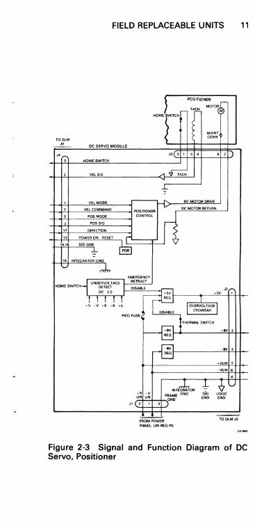
FIELD REPLACEABLE UNITS 11
HOMELlTeH
POSITIONER )~
Tr MOTOR M
~ MAINT
TODlM ~ CONN
J4 DC SERVO MODULE
J' J3 3 1 5 , • 2 • HQMESWrTCH
2 VEL SIG A~ .....
~
1 VEL MODE ,.---- " DC MOTOR DRIVE
7 VEL COMMAND POSITIONER V DC MOTOR RETURN
5 POS MODE CONTROL
3 PCS SIG r 17 DIRECTION
13 POWER ON RESET [,--14,16 SIGGND
~ POR
-15 INTEGRATOR GND
V nJn EMERGENCY
UNDERYOlTAGE RETRACT HOME SWITCH DETECT
D~~~ "r-OC LO +5V 1
J -! +! -! +! REG
OVERVQl TAGEJ
DISABLE CROWBAR
Pica FUSE
Jl
THERMAl SWITCH
H3 REG
rB REG
INTE~OR +v -v FRAME GND UN UN
GND 2 1 3
~
FROM POWER PANEL UN REG PS
+BY 2
-BY 3
+VUN 5
-YUN 6 , -b ,:?~ ~ siG lOGIC
GND GND
~
TO DLM J2
Figure 2-3 Signal and Function Diagram of DC Servo. Positioner

RfW MODULE
}! 13 SERVOJDATA 1
15 SERVO/DATA 2
17 AMP SENSOR H
7 CURRENT IN WRITE HEADS l READ AMP WRITE AMP
1 WRITE DATA ERROR PULSE L HEAD SELECTION ERROR DETECnON
6 WRITE GATEH
4 WRITE GATE L
9 WRITE DATA PULSE L
;:. 1
2
3
4 1 ~'-' ~
1
2
POSITIONER
-I 3 UPPER HEAD
\ i
-( 1
.... ....,
"T1 iii rC ::lJ m ."
~ m LOWER HEAD
3 HEAD SELECT ZERO L 3 \l 2 R/W POWER ON RESET L 4 11 -Dt~ J . I 13 1 HEAD SELECTZERO L 13 1 f'1 \d/ ~ J6" _ 2 R/W POWER ON RESET L 4 'f r-
8 +8V
~'-' 18
+5V 10
-8V FM SUPPLY 20
-8V FM LOGIC 19
-V UN 14,16
~ SIGGND 11,12
'-' V LOGIC GND
Figure 2-4 Signal and Function Diagram of RIW Module, RIW Heads
-....
r..7 __ "
m C Z
~

TODLM JI1
FIEL:D REPLACEABLE UNITS 13
FRONT PANEL
J,
~ 4 LOAD LP H o A -OV
~ 7 RUN L 2 -. 3
'Ri:i'N'sW --READY IND
6 READY LP H ACGiL 8 1\ Ov r--;;-5 SELECT BIT 0 L , 3 SELECT BIT 1 L a ::1 2 ASSERTED 3 -
~
8 FAULT LP H B~j o A -8V
U!..J
-8v :~N~ rs;- .1 9 WR PROT L 2 -.. -8v ~
w~w '0 -OV ,
-:!:-LOGIC GND
-oz-....
Figure 2-5 Signal and Function Diagram of Front Panel

14 FIELD REPLACEABLE UNITS
I lOBUS CONNECTORS ON POWER PANEl
~ ,..-----, DRIVE lOGIC MODULE
3 TT I H I MAJOR STATE LOGIC
4 SS L ~r---t- DR ERR BRUSH CONTROL
I RR, I H
I SPIN UP'DOWN CONTROL
5 I SPINDLE SPEED CONTROL PP I L ~DR RDY
6
: H
POSITIONER CONTROL
NN I
SERVD'DAT A HANDLING 7 I 8
MM L .r---r- SEC PLS GUARD BAND DETECTION
I SECTOR HANDLING
11 HH I L I ERROR DETECTION
12 JJ H ...r---:- STATUS elK STATUS GATHERING I
COMMAND RESPONSE DD I H I 15 CC L STATUS IN
16 I DC POWER DISTRIBUTION
19 Z I H I IN J2 FROM DC SERVO
Y L RD DATA OUT Jl 1, J4, J6. J5 20 I
I I 5V REG FOR liD CABLE DRIVERS
21 W L AND RECEIVERS
22 X H DR CMD
I T
I L I
25 S I H WR DATA
26 I J I L I ~ TO FRONT PANEL
33 34 H H WR GATE - T
_J o TO De SERVO ENABLE
F L
~ G FROM DC SERVO 35
E H SEl
36 1 DRIVE
D L DR SELECT o TO R,W MODULE
37 SEL LOGIC
38 C H
0
N L G TO AC SERVO
29 M H SYS CLOCK
30
39 B POWER --f>--. AC LD ~
RAW 2 FAIL L v SECTOR PULSE
RET 3
VV, UU,LLKK,FF,EE. 1 40
LOG~ GND '-' BB. AA. U, V. LOGiC GND
'--' P,RK,LA
TRANSDUCER SECTOR ,I
rr'" FRAME GND
Figure 2-6 Signal and Function Diagram of Drive Logic Module
Figures 2-7 and 2-8 illustrate the physical location of the FRUs.
Figures 2-9 through 2-14 illustrate the essential component layout of the major FRUs and identify the different versions when appropriate.
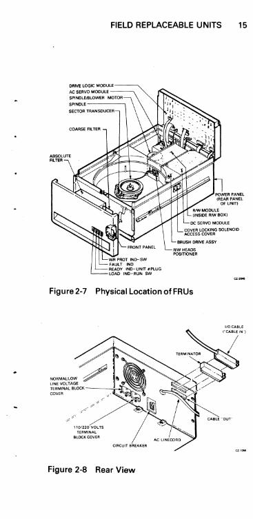
FIELD REPLACEABLE UNITS 15
DRIVE lOGIC MODULE
COARSE FILTER
WR PROT INo- SW FAULT INO READY IND- UNIT #PLUG UlAD INO - RUN SW
DC SERVO MODULE
COVER LOCKING SOLENOID ACCESS COVER
cz .....
Figure 2-7 Physical Location ofFRUs
TERMINAL BLOCK COVER
Figure 2-8 Rear View
"our
16 FIELD REPLACEABLE UNITS
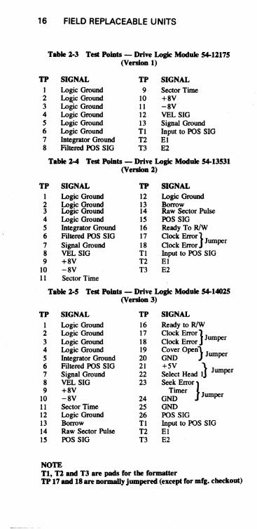
Table 2-3 Test PolDts - Drive Logic Module 54-12175 (Version 1)
TP SIGNAL TP SIGNAL 1 Logic Ground 9 Sector Time 2 Loaic Ground 10 +8V 3 Logic Ground .11 -8V 4 Logic Ground 12 VEL SIG 5 Logic Ground 13 Signal Ground 6 Logic Ground Tl Input to FOS SIG 7 Integrator Ground T2 El 8 Filtered FOS SIG T3 E2
Table 2-4 Test PolDts - Drive Logic Module 54-13531 (Version 2)
TP SIGNAL TP SIGNAL 1 Logic Ground 12 Logic Ground 2 Logic Ground 13 Borrow 3 Logic Ground 14 Raw Sector Pulse 4 Logic Ground 15 FOS SIG 5 Integrator Ground 16 Ready To RIW 6 Filtered FOS SIG 17 Clock Error} Jum r 7 Signal Ground 18 Clock Error pe 8 VEL SIG Tl Input to FOS SIG 9 +8V T2 EI
10 -8V T3 E2 11 Sector Time
Table 2-5 Test PolDts - Drive Logic Module 54-14025 (Version 3)
TP SIGNAL TP SIGNAL
I Logic Ground 16 Ready to R/w 2 Logic Ground 17 Clock Error} Jum r 3 Logic Ground 18 Clock Error pe 4 Logic Ground 19 Cover open} J 5 Integrator Ground 20 GND umper
6 Filtered FOS SIG 21 +5V J J 7 Signal Ground 22 Select Head 1 umper 8 VEL SIG 23 Seek ErrOr} 9 +8V Timer
10 -8V 24 GND Jumper
11 Sector Time 25 GND 12 Logic Ground 26 FOS SIG 13 Borrow Tl Input to FOS SIG 14 Raw Sector Pulse T2 El 15 FOS SIG T3 E2
NOTE Tl, T2 and T3 are pads for the formatter TP 17 and 18 are normally jumpered (except for mfg. checkout)

FIELD REPLACEABLE UNITS 17
54-12175 RL010NLY
NOTE: J11 AND J4 POINT DOWN
54-13531 RL02 OR RL01 W1 IN FOR RL01 W1 OUT FOR RL02
-TP13
VERSION 1 TP1_
TP~ TP7
• ·TP11 -TP9
~~ @ Jo .!(,,~~
J14 J2
00 VERSION 2 W 1 1
....
@~M~J TP15-7- 8-10-9 TP1· ~
NOTE: J4 AND J11 POINT UP • NO TP19 THRU 26
- TP21 00 TP22 TP12
~ ~~~ VERSION 3 wq
54-14025 RL02 OR IIl01 W1 IN FOR RL01 W1 OUT FOR RL02
NOTE: J4 AND J11 POINT UP HAS TP19 THRU 26
TP23 (;) (!)
TP24 .... R R 0:
~ML •• • •• • a... TP15-7- 8-10-9 TP1 I-
NOTE: R DENOTES RED STRIPE
JUMPER TEST LUGS EFFECT 19-20 DEFEAT COVER CLOSED 21-22 SELECT HEAD 1 23-24 DISABLE SKTO
(THESE TEST LUGS ARE CIRCLED)
CZ-2046
Figure 2-9 Drive Logic Mo(jule Layout

18 FIELD REPLACEABLE UNITS
TP3
TP3
TP2 TP1
54-11844 Rl010NlY
R4'OOR40 ........ W2 ........ W,
TP2 TP,
NOTE: ONE JUMPER IN AT A TIME Wl IN FOR RLOl W2 IN FOR RL02
54-13536 ALOl OR RL02
J3 J2 4 4
2 2
3 3
J3 J2 4 4 , 2 2 3 3
Figure 2-10 RIW Module Layout - Top View
,--__ -----,I I/O IN
'--__ -----'Ilia OUT
C3
MOTOR CAP
CZ-2050
Figure 2-11 Power Panel Layout - Front View

FIELD REPLACEABLE UNITS 19
54-11850 AL010NLY
@
® C4'56l ~
54-13534 RL01 OA AL02
W1 IN FOA AL01 OUT FOA RL02
W2 ALWAYS IN
F11'1---HE-AT S-INK-lJ"
=~6 6ol{ ® t@ (3"2"'i) LU....il
Figure2-12 DC Servo Module Layout - Bottom View
NOTE Later versions of the DC Servo Module have the jumpers (WI and W2) on top of the module. Thus, they are accessible through the plastic template.

20 FIELD REPLACEABLE UNITS
J1
R J3 J5
~ ® 3 1
J4 J2 0 QJ) 3 4
1 2
CZ-2048
Figure 2-13 ACServoModuleLayout-FrontView
52 54 53 51 r-- --- -T-----T'--- --"T"""---- ... : 1 ' A ' 1 4'1 : I ' I , , : 2 A B l B: 2 A B 512 A I
....... ~ ...... .,L~ ____ -'-_____ -!.-: ____ 6.!.~ _____ J ........ .1 t ....
;I{---- .... ~. '10 8 6 4 2' : 9 7 5 3 1 ~ J1 '- ________ J
CZ-2051
Figure 2-14 Front Panel Layout - Rear View

CHAPTER 3 FRONT PANEL
FRONT PANEL SWITCHES AND INDICATORS • LOAD indicator is on when the spindle is stopped and the
cover is unlocked. This indicates that the operator can open the cover to .. oad or unload the cartridge.
• LOAD switch is an alternate action switch that is used to start or stop the spindle. The IN position corresponds to RUN and the OUT position to STOP.
• UNIT NUMBER plug has cams on the back to encode the unit number into electrical signals. The corresponding number is stamped on the front for the operator to read. The number can be 0 through 3. The plug also serves as a READY indicator.
• READY indicator is on when the cartridge is up to speed, brush cycle finished, heads loaded, and the heads are "on track". The unit is ready to perform a Read, Write, or Seek operation.
• FAULT indicator is on when certain drive conditions exist. These conditions are shown in Table 4-1 - Drive Conditions.
• WRITE PROT indicator is on when the Write Protect condition is true. It is the result of the state of the WRITE PROT switch.
• WRITE PROT switch is an alternate action switch that establishes the Write Protect condition. The IN position corresponds to the Write Protect state.
21


CHAPTER 4 DRIVE CONDITIONS
Table 4-1 Drive Conditions
FAULT Drive Heads Condition Bit* Light Error Unld. Comment
Device 8 Yes Yes No Set by Drive Select Select and SEC PLS from Error another unit. (DSE) Cleared by Reset
or Power On Reset (POR).
Volume 9 No Yes No Set by Load Heads Check cycle. Cleared by (VC) Reset or POR.
Write 10 Yes Yes No Set during Write Gate Gate if one or more
Error of the following (WGE) occur:
• Drive is not "Ready to Read/Write"
• Drive is Write Protected
• Sector pulse is occurring
• Drive has another error
Cleared by Reset or POR.
Spin 11 Yes Yes Spin-up Timeout Error prevents loading of (SPE) heads. Set by
Spin-up Timeout (40 sec) or Over-speed. Cleared by Reset or POR.
Seek 12 Yes Yes No Set by timeout of Timeout approximately 1.5 (SKTO) sec. Cleared by
Reset or POR.
*Bit in Multipurpose Register after a Get Status command
M~ T?'fLfo(P
23
24 DRIVE CONDITIONS
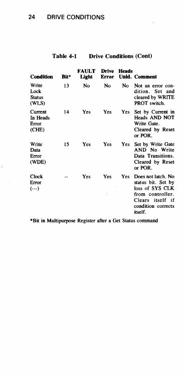
Table 4-1 Drive Conditions (Cont)
FAULT Drive Beads Coaditioa Bit* Light Error UDid. Comment
Write 13 No No No Not an error con-Lock dition. Set and Status cleared by WRITE (WLS) PROT switch.
Current 14 Yes Yes Yes Set by Current in In Heads Heads AND NOT Error Write Gate. (CHE) Cleared by Reset
or POR.
Write 15 Yes Yes Yes Set by Write Gate Data AND No Write Error Data Transitions. (WOE) Cleared by Reset
or POR.
Clock Yes Yes Yes Does not latch. No Error status bit. Set by (---) loss of SYS CLK
from controller. Clears itself if condition corrects itself.
*Bit in Multipurpose Register after a Get Status command

CHAPTERS REGISTER SUMMARY
5.1 RLll/RLVll Register Summary
Table 5-1 ControUer Addressable Registers
Type Register Address (read! Name! (octal) write) Mnemonic Basic Function
774400 R/W Control Status (CS)
774402 R/w Bus Address (BA)
774404 R/W Disk Address (DA)
774406 R/W Multi-purpose (MP)
77&1IJ{)o CONTR6L STATUS REGISTER (eSR)
Bit(s)
o
READ ONLY
Name Drive Ready (DRDY)
Indicates drive ready condition; decodes drive commands and provides overall control functions and error indications
Indicates memory location involved in data transfer during a normal read or write operation
(l) Holds disk address during a data transfer such as Read or Write; or (2) holds the drive command word for a Seek command; or (3) holds the drive command word for a Get Status command
(1) Functions as word counter when transferring read/ write data between UNIBUS and drives; or (2) holds results of a Get Status command; or (3) holds results of a Read Header come mand.
Function When set, this bit indicates that the selected drive is ready to receive a command. The bit is cleared when a seek operation is initiated and set when the seek operation is completed.
25

26 REGISTER SUMMARY
Bit(s) Name Function
1-3 Function Code These bits are set by software to indicate the command to be exe-cuted.
Command execution requires that Bit 7 (Controller Ready) be cleared by software. A zero bit being trans-ferred into bit 7 of the CSR can be considered as a Go bit.
Octal F2 Fl FO Command Code
0 0 0 NoOp 0 (RLI I) or Maint. (RLVII)
0 0 1 Write Check 1 0 1 0 Get Status 2 0 1 1 Seek 3
0 0 Read 4 Header
0 1 Write Data 5 1 0 Read Data 6
Read Data 7 Without Header Check
4-5 Bus Address The two most significant bus ad-Extension Bits dress bits. Read and written as data (BAI6, BAI7) bits 4 and 5 of the CS register but
considered as address bits 16 and 17 of the bus address register.
6 Interrupt When this bit is set by software, the Enable (IE) controller is allowed to interrupt the
processor at the normal command or error termination.
7 Controller Ready When cleared by software, this bit (CRDY) indicates that the command in bits
1-3 is to be executed. When set, this bit ipdicates the controller is ready to accept another command.
8-9 Drive Select These bits determine which drive (DSO, DSI) will communicate with the control-
ler via the drive bus.
\0 Operation When set, this bit indicates that the Incomplete (OPI) current command was not com-
pleted within 200 ms.

REGISTER SUMMARY 27
Bit(s) Name Function
11 Data CRC (DCRC) If OPI (bit 10) is cleared and this bit or Header CRC is set, a CRC error has occurred (HCRC) or Write when reading the data (DCRC). Check (WCE) IfOPI (bit 10) is set and bit 11 is also
set, the CRC error has occurred on the header (HCRC).
IfOPI(bit 10) is cleared and bit 11 is set and the function command was a write check, a write check error (WCE) has occurred.
12 Data Late (DLT) This bit is set during a write when or Header Not the silo is empty but the word count Found (HNF) has not yet reached zero (meaning
that the bus request was ignored for too long). The OPI bit will not be set.
This bit will be set during a read when the silo is full (meaning that the word being read could 'not enter the silo and the bus request has been ignored for too long). The OPI bit will not be set.
When this bit and OPI are both set, a 200 ms timeout occurred while the controller was searching for the correct sector to read or write (no header compare - HNF).
Error Summary Bits
Error 12 11 10 OPI 0 0 1 Read Data CRC 0 I 0 ,
Write Check 0 I 0 Header CRC 0 1 1 Data Late I 0 0 Header Not Found 0
13 Non-Existent This bit is set when the addressed Memory memory does not respond within the (NXM) proper time frame during a direct
memory access (DMA) data trans-fer.

28 REGISTER SUMMARY
BIt(s) Name
14 Drive Error (DE)
15 Composite Error (ERR)
77404-0'7.. BUS ADDRESS REGISTER IBARI
BIt(s)
0-15
Name BAO thru BAI5
BIt(s) Name
o I
2 Direction (DIR)
Flmc:ti0D
This bit is tied directly to the DE interface line. When set. it indicates that the selected drive has flagged an error. (The source of the error can be determined by executing a Get Status command.)
DE can be cleared by executing a Get Status command with. bit 3 of the DA register set.
When set. this bit indicates that one or more of the error bits (bits 10-14) is set. If the IE bit (bit 6 of CS) is set and an error occurs (which sets bit 7). an interrupt will be initiated.
READIWRITE
Flmc:ti0D These bits point to the Unibus address that data is to be transferred to/from. Normally- a memory address. BAI6 and BAI7 are intheCSR bits 4 and 5.
Function Must be a 1.
Must be a O.
This bit indicates the direction in which a seek is to take place. When the bit is set. the heads move toward the spindle (to a higher cylinder address). When the bit is cleared. the heads move away from the spindle (to a lower cylinder address). The actual distance moved depends on the cylinder address difference (bits 7-15).

:
REGISTER SUMMARY 29
Bit(s) Name Function
3 Must be a O.
4 Head Select (HS) Indicates which head (disk surface) is selected. A one indicates the lower head; a zero, the upper head.
5-6 Reserved.
7-15 Cylinder Address Indicates the number of cylinders Difference the heads are to move on a seek. DF08:00
7., 'Iljo'l OAR DURING READING OR WRITING DATA COMMANDS
Bit(s) 0-5
6
7-15
Name Sector Address SA 05:00
Head Select (HS)
Cylinder Address CA 08:00
7 7 '+ 'l-D If-OAR DURING GET STATUS COMMAND
I. I' 13 12
I x I x I x I x I
Bit(s) Name o
11 10 09
x I x I x
Get Status (OS)
2
Function Address of one of the 40 sectors on a track. •
Indicates which head (disk surface) is to be selected. A one indicates the lower head; a zero, the upper head. The correct track (head and cylinder) must be previously selected by a Seek.
Address of the cylinder being accessed.
I x I 0 I 0 I 0 I 0 I RSTI 0 11 11 I
Function Must be a I.
Must be a I, indicating to the drive that the status word is being requested. At the completion of the Oet Status command, the drive status word is read into the controller Multipurpose (MP) register.
Must be a O.

30 REGISTER SUMMARY
Bit(s) Name
3 Reset (RST)
4-7
8-15 77+<fC7~
MPR AFTER GET STATUS COMMAND
Bit(s) Name 0-2 State C:A
STC:A
Bit C 0 0 0 0 1 1
3 Brush Home (BH)
4 Heads Out (HO)
5 Cover Open (CO)
6 Head Select (HS)
7 Drive Type (DT)
8 Drive Select Error (DSE)
9 Volume Check (VC)
Function
When this bit is set, the drive clears its error register before sending a status word to the controller.
Must be a o. Not used during a Get Status.
Function These bits defme the state of the drive.
State Bit Defmitions Bit Bit B A Definition 0 0 Load Cartridge 0 1 Spin Up 1 0 Brush Cycle 1 1 Load Heads 0 0 Seek (Track Counting) 0 1 Lock On (Keeping
on track) 0 Unload Heads 1 Spin Down
Set when the brushes are home.
Set when the heads are over the disk.
Set when the drive access cover is open or the dust cover is not in place.
Indicates the currently selected head. A zero indicates the upper he~d; a one, the lower head.
A zero indicates an RLOI; a one, an RL02.
Set when a multiple drive selection is detected.
Set when a cartridge is spun up. Cleared by execution of a Get Status command with Bit 3 asserted.

REGISTER SUMMARY 31
Bit(s) Name Function
10 Write Gate Error Set during Write Gate if one or more (WGE) of the following conditions occur.
• Drive is not "Ready to Read/ Write"
• Drive is Write Protected • Sector pulse is occurring • Drive has another error
\1 Spin Error (SPE) Set when spindle has not reached speed in the required time during spin-up or when spindle speed is too high.
12 Seek Time Out Set when the heads do not come on Error (SKTO) track in the required time during a
Seek command or when "Ready to Read/Write" is lost while the drive is in position (lock-on) mode.
13 Write Lock (WL) Set when the drive is Write Pro-tected.
14 Current Head Error Set if Write Current is detected in (CHE) the heads when Write Gate is not
asserted.
15 Write Data Error Set if Write Gate is asserted but no (WDE) transitions are being detected on the
Write Data line.
77't'f o ? MPR AFTER READ HEADER COMMAND
15 14 13 12 11 10 09 08 07 06 05 04 03 02 01 00
ZEROES
15 14 13 12 11 10 09 08 07 06 05 04 03 02 01 00
CAC
Bit(s) Name Function 0-5 SAO:SA5 Sector Address
6 HS Head Select - Upper head=O, lower head= I
7-15 CAO:CA8 Cylinder Address

32 REGISTER SUMMARY
774-4-0 c.:. MPR DU~'NG READIWRITE COMMANDS FOR WORD COUNT
Bit(s) 0-12
13-15
Name Word Count WC 12:00
Function Contains the two's complement of total number of words to be transferred.
Must he ones.
MP Register Programming Note - The RLOI/ RL02 Disk DrIve will not do spiral read/writes. If data is to be transferred past the end of the last sector of a track, it is necessary to break up the operation into the foUowiDg steps.
I. Program the data transfer to terminate at the end of the last sector of the traek.
2. Program a seek to the next track. This can be either a head switch to the other surface but same cylinder or a head switch and move to the next cylinder.
3. Program the data transfer to continue at the start of the fJrSt sector at the next traek.
5.2 RL8-A Instruction Set and Register Summary
Table S-2 RLS-A Instruction Set
Octal Code Mnemonic Function
6600 RLDC Clear controller, all registers, AC and flags. (Do not use to terminate a disk function.)
6601 RLSD Skip on function done. Then clear if set to a one.
6602 RLMA Load break MA register from AC 0: 11
6603 RLCA Load command register A from AC 0:11
6604 RLCB Load command register B from AC 0: 11, execute command
6605 RLSA Load sector address register from AC 0:5

0daI Code
66{)7
6610
6611
6612
6613
6614
6615 6617
Table 5-2
RLWC
RRER
RRWC
RRCA
RRCB
RRSA
RRSI
RLSE
REGISTER SUMMARY 33
RLB-A Instruction Set (Cont)
Load word count register from AC 0:11
Read error register into AC 0, I, 2, 10, 11
Read word count register into AC 0: 11
Read command register A into AC 0:11
Read command register B into AC 0:11
Read sector address register into AC 0:5
Read silo word into AC 0: 11
Skip on composite error, then clear if set to a one.
COMMAND REGISTER A DURING A SEEK COMMAND
00 01 02 03 04 05 06 07 08 09 10 11
'~----------~vr----------~I CYLINDER DIFFERENCE
Bit(s) Name Function ACO Direction (DIR)
ACI Head Select (HS)
AC2
AC3: II Cylinder Address Difference
This bit indicates the direction in which a seek is to take place. When the bit is set, the heads move toward the spindle (to a higher cylinder address). When the bit is cleared, the heads move away from the spindle (to a lower cylinder address). The actual distance moved depends on the cylinder address difference (bits 3-11).
Indicates which head (disk surface) is to be selected. A one indicates the lower head; a zero, the upper head.
Spare
Indicates the number of cylinders the heads are to move on a seek.

34 REGISTER SUMMARY
COMMAND REGISTER A DURING A AEADIWRITE DATA COMMAND
00 01
I 0 I HS I
Bit(s) Name ACO
02 03 04
0 I MSBI
ACI Head Select (HS)
AC2
AC3:ll Cylinder Address
05 06 07 08
V CYliNDER ADDRESS
Function Must be zero
09 10 " I LS8 I
Indicates which head (disk surface) is to be selected. A one indicates the lower head; a zero, the upper head. The correct track (head and sector) must be previously selected by a Seek.
Must be zero
Cylinder address.
COMMAND REGISTER B
Bit(s) Name Function ACO Reserved
ACI Maintenance The contents of the Disk Address (DA) register are looped back to the silo for maintenance purposes. Bit 2 of Command Register B must also be set for this function to work cor-rectly.
AC2 Mode When set, this bit indicates that the data field will be 256 8-bit words per sector. When zero, the data field will be truncated to 170 12-bit words per sector. This bit must be set when a Maintenance, a Get Status or a Read Header command is to be executed.
AC3 Interrupt Enable When this bit is set, the controller is (IE) allowed to interrupt the processor at
the conclusion of a normal com-mand or error termination.
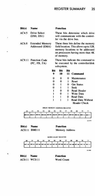
Blt(s) Name
AC4:5 Drive Select (DSO, DSI)
AC6:8 Extended Memory Addressed (EMA)
AC9:II Function Code (PC, FB, FA)
REGISTER SUMMARY 35
Function
These bits detennine which drive will communicate with the control-ler via the drive bus.
These three bits define the memory field location. This allows up to 32K memory locations to he addressed on processors having more than 4K of memory.
These bits indicate the command to be executed by the controller/disk subsystem.
Bit Bit Bit 9
o o o o 1 I I I
10
o o I I o o 1 1
11 Command
o Maintenance 1 Reset o Get Status 1 Seek o Read Header 1 Write Data o Read Data 1 Read Data Without
Header Check
BREAK MEMORY ADDRESS REGISTER
Blt(s) Name ACO: 11 BMO: 11
Bit(s) Name ACO:ll WCO:ll
Function Memory Address
WORD COUNT REGISTER
Function Word Count

36 REGISTER SUMMARY
SILO BUFFER - HEADER WORDS
00 01 02 03 04 05 06 07 08 09 10 " NOT DEFINED I LSB I HS I MSB I I LSB I
WORD 1 \.....r' ,
V )
CYLINDER SECTOR ADDRESS ADDRESS
00 01 02 03 04 05 06 07 08 O. 10 " NOT DEFINED I MSB I
WORD 2 v CYLINDER ADDRESS
NOT DEFINED 0 I 0 I 0 I 0 I 0 I 0 I 0 I 0
WORD 3
NOT DEFINED I 0 I 0 I 0 I 0 I 0 I 0 I 0 0 I WORD 4
NOT DEFINED
WORD 5 v~------' HEADER CRG
NOT DEFINED I MSB I WORDB \. v
HEADER CAG
Bit(s) Name ACO:3
AC4
AC5
Cyl Add
HS
AC6: 11 Sec Add
Bit(s) Name ACO:3
WORD 1 - HEADER
Function Undefined
LSB of Cylinder Address
Head Select - lower head upper head = 0
Sector Address
WORD 2 - HEADER
Function Undefined
1,
AC4: 11 Cyl Add Cylinder Address - eight high order bits

REGISTER SUMMARY 37
WORD 3 - HEADER
Bit(s) Name Function ACO:3 Undefined
AC4:11 Zeros
WORD 4 - HEADER
Bit(s) Name Function ACO:3 Undefined
AC4:11 Zeros
WORD 5 - HEADER
Bit(s) Name Function ACO:3 Undefined
AC4:11 CRC Eight LSB of CRC word
WORD 6 - HEADER
Bit(s) Name Function ACO:3 Undefmed
AC4:11 CRC Eight MSB of CRC word
SilO BUFFER - STATUS WOAD 1
00 01 02 03 04 05 06 07 08 09 10 11
NOT DEFINED
WORD 1
Bit(s) Name Function ACO:3 Undefined
AC4 Drive Type A zero indicates an RLOl; a one, an RL02.
AC5 Head Select (HS) Indicates currently selected head. A zero indicates the upper head; a one, the lower head.
AC6 Cover Open (CO) Set when the drive access cover is open or the dust cover is not in place.
AC7 Heads Out (HO) A one indicates that the heads are over the disk; a zero indicates that the heads are home.

38 REGISTER SUMMARY
Bit(s)
AC8 AC9:11
Bit(s)
ACO:3
AC4
AC5
AC6
AC7
AC8
Name
Brush Home (BH) State Bits
Function
Set when the brushes are home. These bits define the state of the disk drive.
State Bit Def"mitions Bit Bit Bit C B A Def"mition
0 0 0 Load Cartridge 0 0 1 Spin-up 0 1 0 Brush Cycle 0 1 I Load Heads 1 0 0 Seek (Track
Counting) 0 Lock-on (keeping
on track) 0 Unload Heads
Spin-down
SILO BUFFER - STATUS WORD 2
00 01 02 03 04 05 06 07 08 09 10 11
NOT OEFINED I WDE I CHE I WL I STO I SPE I WGE I VC I DSE I WORD 2
Name Function Undefined
Write Data Error This bit is set when the Write Gate is (WOE) on but no transitions were detected
on the Write Data line.
Current Head Error This bit is set when Write Current is (CHE) detected in the heads but the Write
Gate was not asserted.
Write Lock (WL) Set when the drive is Write Pro-tected.
Seek Time Out Set when the heads do not come on Error (SKTO) track in the required time during a
Seek command or when "Ready to Read/Write" is lost while the drive is in position (lock-on) mode.
Spin Error (SPE) Set when the spindle does not come up to speed within 40 seconds or when the spindle speed is too high.

;;
REGISTER SUMMARY 39
AC9 Write Gate Set if Write Gate is asserted and one Error or more of the following conditions (WGE) is true.
I. Drive is not "Ready to Read! Write"
2. Drive is Write Protected 3. Drive is in the midst of sector
time 4. Drive has another error asserted
ACIO Volume Check Set when a cartridge has heen spun (VC) up. This bit is reset by a Reset com-
mand.
ACll Drive Select Error Set when one or more drives have (DSE) the same numher (unit select plug)
or have responded to the same numher.
SECTOR ADDRESS REGISTER
Bit(s) Name ACO:5 SAO:5
Function Sector Address
ERROR REGISTER
00 01 02 03 04 05 06 07 08 09 10 11
OCRe
HeRe
-Bit(s) ACO
ACI
OPI DLT
HNF
'--
Name Data CRC (DRCR) or Header CRC (HCRC)
Operation Incomplete (OPI)
NOT DEFINED I DE IDRDVI
Function If OPI is deared and this bit is set, the CRC error occurred in the data (DCRC). If OPI is set and this bit is also set, the CRC error occurred on the header (HCRC).
When set, this bit indicates that the current command was not completed within 200 ms. It is also used in conjunction with bits 0 and 2 of this register.

40 REGISTER SUMMARY
Bit(s)
AC2
Name
Data Late (DLT) or Header Not Found (HNF)
ACO:2 Error Code
AClO Drive Error (DE)
ACll Drive Ready (DRDY)
Function
This bit is set during a Write if the silo is empty and the word count is not yet zero (meaning that no word was available for writing). OPI will not be set.
This bit is set during a Read if the silo is full and the word count is not yet zero (meaning that the word being read could not enter the silo). OPI will not be set.
When this bit and OPI are both set, then a 200 ms timeout occurred while the controller was searching for the correct sector to read or write (no header compare - HNF).
Summary
Error Bits 00 01 02
DLT 0 0 1 OPI 0 1 0 HNF 0 1 1 DCRC I 0 0 HCRC 1 1 0
This bit is tied directly to the Drive Error interface line. When set, it indicates that the selected drive has flagged an error. The source of the error can be determined by a Get Status.
The DE bit is cleared with a Reset command to the drive.
When set, this bit indicates that the selected drive is ready to receive a command. The bit is cleared when a Seek operation is initiated and set
• again when the Seek operation is completed.
li '!
i , r
~'"
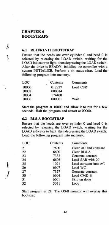
CHAPTER 6 BOOTSTRAPS
6.1 RLll1RLVll BOOTSTRAP Ensure that the heads are over cylinder 0 and head 0 is selected by releasing the LOAD switch, waiting for the LOAD indicator to light, then depressing the LOAD switch. After the drive is READY, initialize the controller with a system INITIALIZE. Perform a bit status clear. Load the following program into memory.
LOC 10000 10002 10004 10006
Contents 012737 000014 174400 000001
Comments Load CSR
Wait
Start the program at 10000 and allow it to run for a few seconds. Halt the program and restart at 00000.
6.2 RLS·A BOOTSTRAP Ensure that the heads are over cylinder 0 and head 0 is selected by releasing the LOAD switch, waiting for the LOAD indicator to light, then depressing the LOAD switch. Load the following program into memory.
LOC Contents Comments 21 7600 Clear AC and constant 22 6600 Clear RL8-A 23 7332 Generate constant 24 6605 Load SAR with 20 25 1021 Load constant into AC 26 6607 Load WC 27 7327 Generate constant 30 6604 Load CMD B 31 6601 Skip on done 32 5031 Loop
Start program at 21. The OS·8 monitor will overlay this bootstrap.
41


CHAPTER 7 TOGGLE-IN PROGRAMS
7.1 HEAD SELECTION PROGRAM FOR RL11/RLVll The following program causes Head 1 (lower head) to be selected (on unit 0) if the WRITE PROTect switch is in and Head 0 (upper head) to be selected if the switch is out.
1000 012700 Housekeeping 1002 174400 1004 012701 1006 174404 1010 105710 Wait 1012 100376 1014 012711 Get Status Command 1016 000013 1020 012710 1022 000004 1024 105710 Wait 1026 100376 1030 013702 Status Word 1032 174406 1034 006302 1036 010203 1040 006303 1042 lo;i702 Check HS Bit 1044 100405 1046 005703 Check WL Bit 1050 100357 Equal, Loop 1052 012711 Set HS Bit
'" 1054 000021 1056 000404 Go to Seek Command 1060 005703 Check WL Bit 1062 100752 Equal, Loop 1064 012711 Reset HS Bit 1066 000001 1070 012710 Seek Command 1072 000006 1074 000745 Loop
43

44 TOGGLE-IN PROGRAMS
7.2 HEAD SELECTION PROGRAM FOR RLS-A The following program causes Head 1 (lower head) to be selected (on unit 0) if the WRITE PROTect switch is in and Head 0 (upper head) to be selected if the switch is out.
200 6600 Clear Controller 201 1234 202 6604 Get Status Command 203 6601 Wait 204 5203 205 6615 First Word of Status 206 0232 207 7640 Check HS Bit 210 5217 HS=I, Go to 217 211 6615 Second Word of Status 212 0233 213 7650 Check WL Bit 214 5201 HS=WL, Go to 201 215 7332 216 5224 217 6615 Second Word of Status 220 0233 221 7640 Check WL 222 5201 HS=WL, Go to 201 223 7300 224 6603 HS to Command REG ~ 225 7325 226 6604 Seek Command to Command REG B 227 6601 Wait 230 5227 231 5201 Loop to 201 232 0100 Constant 233 0040 Constant 234 1002
7.3 GET STATUS (WITH OR WITHOUT RESET) ON AN RLllIRL Vll SUBSYSTEM
To accomplish this it is necessary to:
1) Deposit a 3 into DAR at 774404 (or 13 to Reset) 2) Deposita4intoCSRat774400(or404, 1004, 1404 for
units 1, 2, 3) 3) Wait for operation to be complete 4) Examine contents of MPR at 774406.

TOGGLE-IN PROGRAMS 45
On some PDP-II systems this can be accomplished manually using the console. On other PDP-II systems it is necessary to run a program such as given below. Start at 1000 and when it halts, examine memory location 1032.
To get status on unit 1,2, or 3 modify location 1010 to 404, 1004, or 1404.
To reset drive modify location 1002 to 13.
1000 012737 Get Status Command 1002 000003 Use 13 to Reset 1004 174404 1006 012737 1010 000004 Use 404, 1004, 1404 for Units 1, 2, 3 1012 174400 1014 105737 Wait 1016 174400 1020 100375 1022 013737 Move Result to Memory 1024 174406 1026 001032 1030 00000o Halt 1032 00000o Result
7.4 GET STATUS ON AN RLS-A SUBSYSTEM The following program will GET STATUS from unit O. To access unit 1,2,3 change location 212 to 1102,1202,1302.
Start the program at 200 - at the fIrst halt, the first byte of the status word is displayed in the accumulator - at the second halt, the second byte is displayed.
200 7300 201 1212 202 6604 203 6601 204 5203 205 6615 206 7402 207 6615 210 7402 211 5200 212 1002
Get Status
Wait
Get First Byte Halt and Display First Byte Get Second Byte Halt and Display Second Byte Jump to Start Constant

46 TOGGLE-IN PROGRAMS
7.S OSCILLATING SEEK FOR RLllIRLVll The following program will cause unit zero to perfonn an oscillating seek. To drive units other than unit 0, swap the unit number plugs or modify locations 1044 and 1054 to reflect the unit number in bits 8 and 9.
The number of cylinders involved is inserted into bits 15 through 7 and bit 0 is set in the switch register before starting the programs at 1000. If no switch register is available, modify location 1012 from 177570 to 001060 and put the number of cylinders in bits 15 through 7 and set bit 0 in location 1060.
The common values for the switch register are:
Number of cylinders (in decimal)
Value of Switch Register (in octal)
1000 1002 1004 1006 1010 1012 1014 1016 1020 1022 1024 1026 1030 1032 1034 1036 1040
1 85
170 255 511
012706 001000 012700 174400 013701 177570 004537 001032 042701 000004 004537 001032 000767 105710 100376 010137 174404
Set Stack Pointer
000205 025205 052405 077605 177605
Set Device Address into RO
Set Difference into Rl
Go Seek
Change direction bit in Rl
Go Seek
Loop back Wait
Seek
1042 1044 1046 1050 1052 1054 1056
012710 000006 105710 100376 012710 000010 000205
TOGGLE-IN PROGRAMS 47
Wait
Read Header to kill time for SKTO.
Return
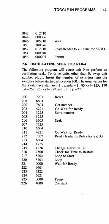
7.6 OSCILLATING SEEK FOR RL8-A
The following program will cause unit 0 to perform an oscillating seek. To drive units other than 0, swap unit number plugs. Insert the number of cylinders into the switches before starting at location 200. The usual values for the switch register are: I cylinder= I, 85 cyl= 125, 170 cyl=252, 255 cyl=377 and 511 cyl=777.
200 201 202 203 204 205 206 207 210 211 212 213 214 215 216 217 220 221 222 223 224 ~25 226
7201 6604 7604 4221 3225 1225 6603 7325 6604 4221 7307 6604 1225 1226 7500 5202 5203 0000 6601 5222 5621 0000 4000
Reset
Get number Go Wait for Ready Store number
Seek
Go Wait for Ready Read Header to Delay for SKTO
Change Direction Bit Check for Time to Restore Loop to Start Loop Wait for Ready
Temp Constant

CHAPTERS DIAGNOSTICS
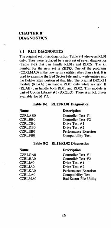
8.1 RLlI DIAGNOSTICS The original set of six diagnostics (Table 8-1) drove an RLOI only. They were replaced by a new set of seven diagnostics (Table 8-2) that can handle RLOls and RL02s. The kit number for the new set is ZB283. One of the programs (CZRLMAO) in the new set is a utility rather than a test. It is used to examine the Bad Sector File and to write entries into the field-written portion of that file. The original DECXll module (RLAA) can handle RLOI only while revision B (RLAB) can handle both RLOI and RL02. This module is part of Option Library #5 (DXQLQ). There is an RL driver available for M.P.G.
Table 8-1 RLIl/RLOI Diagnostics
Name CZRLABO CZRLBBO CZRLCBO CZRLDBO CZRLEBO CZRLFBO
Description Controller Test #1 Controller Test #2 Drive Test # 1 Drive Test #2 Performance Exerciser Compatibility Test
Table 8-2 RLIl/RL02 Diagnostics
Name CZRLGAO CZRLHAO CZRLIAO CZRUAO CZRLKAO CZRLLAO CZRLMAO
Description Controller Test # 1 Controll<!t- Test #2 Drive Test #1 Drive Test #2 Performance ExerCiser Compatibility Test Bad Sector File Utility
49
50 DIAGNOSTICS
8.2 RLVll DIAGNOSTICS The RL V 11 subsystem is tested with the same set of diagnostics as the RL11 except that the RL VII required an additional test (CVRLAAO) for the MAINT command. Kit number ZT285 includes kit ZT283 plus CVRLAAO. Since CVRLAAO is a diskless controller test it can handle either an RLOI or an RL02.
8.3 RLS-A DIAGNOSTICS The original set of diagnostics (Table 8-3) could handle only the RLOI drives. The new set of diagnostics (Table 8-4) can handle RL02 only (except AJRLACO which can handle either an RLOI or an RL02). Kit number ZF241 includes the six diagnostics plus the DECX8 module.
Table 8-3 RL8-A1RLOI Diagnostics
Name AJRLAAO AJRLBAO AJRLCAO AJRLDAO AJRLEAO AXRLAAO AJRLGAO
Description Diskless Control Test Drive Test #1 Drive Test #2 Compatibility Verification Performance Exerciser DECX8 Module Pack Verification
Table 8-4 RL8-A1RL02 Diagnostics
Name AJRLACO AJRLHAO AJRLIAO AJRUAO AJRLKAO AJRLLAO -AXRLBAO
Description Diskless Control Test Seek/Function Read/Write Drive Compatibility Performance Exerciser Pack Verify DECX8 Module
8.4 DIAGNOSTIC SUPERVISOR 8.4.1 Hardcore Questions
1. The statement "TYPE TWO CHARACTERS FOUR SECONDS APART" will be asked when no clock is on the system. The system will then subdivide the spacing for use as a clock.

DIAGNOSTICS 51
2. The prompt "DS-C>" is requesting one of eleven superior "commands ;' which are:
• ST A - STArt diagnostic and then produce questions for generation of the diagnostic parameter ("P") tables.
• RES - REStart diagnostic at the point following the hardware questions. The "P" tables set up by the ST A command will be used.
• CON - CONtinue the diagnostic at the beginning of the subroutine that was being executed when the diagnostic was halted by an error or a control "C".
• PRO - PROceed testing with the diagnostic at the starting address of the subroutine following the one that caused the error report.
• DIS- DISplay the hardware "P" tables for all the drives being tested.
• DRO - DROp the desired units from being tested. "UNITS, "in this case refers to the" P" table unit numbers, not necessarily the device unit numbers. The DIS command will give the operator the device unit number.
• ADD - ADD units back into the testing sequence after they had been dropped by the DRO command.
• PRI - PRInt any performance or statistical tables accumulated by the diagnostic.
• FLA - FLAgs command - The current setting of all the flags set up under the ST A command are printed out for inspection.
• ZFL - Zero FLags command - All current flags set up by the ST A command are cleared by this command.
• CCI - Create Core Image command - This command enables a BIC file to be created on these diagnostics to be run under the XXDP media. (See listing for directions.)

52 DIAGNOSTICS
3. Program Parameter Changes - Type in any combination of the following parameters to affect the indicated commands.
With the ST A command:
a. DS-C>ST NTESTS: Insert test numbers shown in the appropriate diagnostic listing; e.g., 1:2 means tests 1 and 2, or 1-5:8-10 means tests 1 through 5 and 8 through 10.
b. DS-C>STNTESTS:6/PASS: Insert the-number of passes the diagnostic should take before halting.
c. DS-C>ST NTESTS:6/PASS:2/FLAGS: Insert any of these mnemonic(s) representing a program flag(s):
• HOE - Halt On Error • LOE - Loop On Error • IER - Inhibit Error Report • IBE - Inhibit Basic Error reporting .IXE - Inhibit eXtended Error reporting • PRI - PRInt messages on line printer • PNT - PriNT test numbers as they are being
executed • BOE - Bell On Error • UAM - Bypass'manual intervention tests .ISR - Inhibit Statistical Reports • IDR - Inhibit DRopping of units
d. DS-C>STA/TESTS:BOE:IDR/EOP: Insert a number equalling the pass intervals at which the end of pass message will be printed; e.g., every other pass, every third pass, etc.
EXAMPLE:
Using all the possible parameter changes, the ST A command would look like this:
DS-C>ST NTESTS:6/PASS:2/FLAGS:IER:PNT: BOE:IDR/EOP:3

DIAGNOSTICS 53
With the RES command: Use TESTS, PASS, FLAGS and/or UNITS to be tested; e.g., DSC>RESrrESTS:6/UNITS:I (this will run only test 6 on the device specified in "P" table I).
With the other commands:
CON command: PRO command: DRO command: DIS command: ADD command: PRI command: FLA command: ZFL command: CCI command:
8.4.2 Console Controls
Use PASS or FLAGS only use FLAGS only use UNITS only use UNITS only use UNITS only no variations no variations no variations use TESTS, PASS or FLAGS
I. Control "C" causes testing to cease and a return to the start (DS-C».
2. Control "z" causes default values to be taken in any of the three operator dialogues.
3. Control "0" causes a supression of typeouts for the remainder of the diagnostic or until another control' '0" is typed.
8.4.3 Hardware Questions
I. Supervisor "P" (Parameter) tables are built here, one for every unit to be tested.
2. "UNITS" pertains to the "P" table number, not the device unit number. If there is doubt as to which unit number has been assigned to which drive, the DIS command (see above) will supply the necessary information.
8.4.4 Software Question
"CHANGE SW(L)?" asks if any ofthe software parameters are to be changed. A "Y" will cause various questions to be asked. Fordetails, refer to the individual program document.


CHAPI'ER 9 CHECKS, ADJUSTMENTS AND ALIGNMENTS
9.1 INTRODUCTION Many of the checks, adjustments and alignments described in this chapter deal with the Drive Logic Module (DLM). Because there are ,three different versions of the DLM, it is necessary to fIrst identify the particular type of module on the drive being serviced. The three versions are shown in Figure 2-9.
• Version I (Part No. 54-12175) can be identifIed by the fact that the two Berg connectors in the lower right hand of the module point down, while the other two along the bottom row point up. This board will only operate in an RLOl.
• Version 2 (Part No. 54-13531), has all four connectors in the bottom row pointing up, as in Figure 2-9. This module will function in an RLOI or an RL02.
• Version 3 (Part No. 54-14025) has the same arrangement of Berg connectors as Version 2,. but it also has test lugs (shown in Figure 2-9) that are not on either of the other two modules.
The service jumpers used in these checks and adjustments are listed in Table 9-1.
Table 9-1 Service Jumpers for Drive Logic Module
Defeat Cover Defeat Defeat Select
Version Switch POS SIG SK TO Head 1
E33-3 to TP8 to E17-6 to E33-7 ground E17-7
2 E54-12 to TP6 to EIO-8 to E54-7 ground EIO-7
3 TP19 to TP6 to TP23 to TP21 to TP20 groun4'-;') TP24 TP22
Tables 2-3, 2-4 and 2-5 list ground points.
In the course of performing some of the alignments, it is necessary to select Head 1 and then later reselect Head o. The methods for accomplishing this are shown in Table 9·2.
55
56 CHECKS, ADJUSTMENTS AND ALIGNMENTS
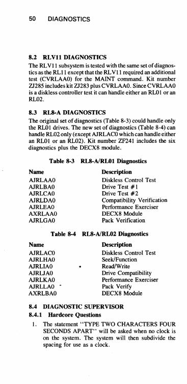
Table 9-2 Methods for Selecting Heads
For a PDP-II-based subsystem:
DLM Version lor 2
Load DZRLCXX or CZRLIXX and run head alignment routine. Having the WRIT PROT switch in selects Head I: having it out selects Head O.
For a PDP-8-based subsystem:
Load AJRLBXX or AJRLHXX and run head alignment routine. Having the WRIT PROT switch in selects Head I; having it out selects Head O.
NOTE
DLM Version 3
Jumper TP21 to TP22 to select Head 1. Removing the jumper selects Head O.
Same as above
If diagnostics are not available, toggle in the appropriate program shown in Chapter 7.
9.2 VOLTAGE CHECKS The DC Servo module template indicates voltage test points. Check the following voltages.
Voltage Limits
+Vun -Vun +5V +SV -SV
+14Vto +ISV -14V to -ISV
+4.S5V to +5.35V +7.7V to +S.3V -7.7V to -S.3V
The regulators on the DC Servo module are not adjustable. If a voltage is out of tolerance, the faulty FRU should be replaced.
The + 5V can be killed by a blown pico fuse, a thermal switch on the DC Servo heat sink, an overvoltage crowbar, or a home switch on the positioner not closed during power up.

CHECKS, ADJUSTMENTS AND ALIGNMENTS 57
9.3 SECTOR TRANSDUCER OUTPUT CHECK This check verifies a correct output of the sector transducer.
A. Required Tools:
I . Oscilloscope with probe 2. DIP clip
B. Check:
-r-.35V.
to 1.5V.
~
I. Remove both top cover assemblies. 2. Install cartridge. 3. Defeat the cover interlock (Table 9-1). 4. Depress LOAD switch. 5. While waiting for the heads to load onto the
pack, set up the oscilloscope (sync internal negative-going). Set vertical coupling to AC.
6a. Version I of DLM: Place oscilloscope probe on E8 pin 8.
6b. Version 2 ofDLM: Place oscilloscope probe on TPI4.
6c. Version 3 ofDLM: Place oscilloscope probe on TPI4.
7. The signal displayed on the oscilloscope should be similar to that shown in Figure 9-1. The peak output of the negative portion of the waveform should be between O.35Vp and 1.5Vp.
l
I 1\ .I. \
~ ~.
\ ~ V
TIME = 100 /lSEC/DIV. VOLTS = 200 MViDIV.
, +V.
1/\ \
1 , I
OV.
I 'I
-v.
MA·1602
Figure 9-1 Sector Transducer Output

58 CHECKS, ADJUSTMENTS AND ALIGNMENTS
NOTE The waveform must be negative-going fIrst.
8. If the specification cannot be"met, the sector transducer must be replaced.
9.4 SECTOR PULSE TIMING CHECK This is a check of the sector pulse width and repetition rate. The repetition rate is a function of spindle speed.
A. Required Tools:
Oscilloscope with probe.
B. Check: I. Remove both top cover assemblies. 2. Defeat cover interlock (Table 9-1). 3. Install cartridge. 4. Depress LOAD switch. 5a. Version 1 of DLM: Place the probe on TP9. 5b. Version 2 of DLM: Place the probe on TPII. 5c. Version 3 of DLM: Place the probe on TPII. 6. Set the oscilloscope to sync internal, negative
going. The signal displayed on the oscilloscope should be the same as in Figure 9-2. Sector pulse width should be 62.5 microseconds. Correct disk speed ranges from 594 microseconds to 639 microseconds, with 624 being the desired norm. The sector pulses should be stable at some time period within that range.
9.5 POSITIONER RADIAL ALIGNMENT
The positioner radial alignment checks assure that the conditions listed below are true.
• The servo bursts (as read by the read/write heads) must occur during the correct time relative to the sector pulse (as detected by the sector transducer at the hub). Because the sector transducer is fixed, changing the head postioner location will affect this timing relationship.
• The servo burst/sector timing relationship must be the same at track 0 as it is at the innermost track because the head carriage moves straight toward the center of the disk.

CHECKS. ADJUSTMENTS AND ALIGNMENTS 59
- 62.5 JLS
62~ IlS
TIME = 100 IlS/DIV. VOLTS = 2v/DIV. CZ-l078
Figure 9-2 Sector Pulse Timing
A. Tools Required:
I. Oscilloscope with two probes 2. Two flat-blade screwdrivers 3. One Phillips head screwdriver 4a. One DIP clip, one pin-to-pin jumper and one
test lead, or 4b. Two pin-to-pin jumpers and two DIP clips 5. Diagnostic listed in Table 9-2.
B. Positioner Alignment Check:
I. Remove both top cover assemblies. 2. Defeat POS SIG, SKTO and cover interlock
(Table 9-1). 3. Place the Read/Write module box assembly up
and out of the way of the carriage assembly. 4. Install cartridge. 5. Depress LOAD switch. 6. Wait for heads to load onto the pack. 7. Disable servo drive to the carriage by discon
necting the in-line connector (Figure 9-3). 8. Select Head I (Table 9-2).

60 CHECKS, ADJUSTMENTS AND ALIGNMENTS
9. Place the Channel B oscilloscope probe on TP2 of the Read/ Write module (data) and Channel B ground on any signal ground (TPI - TP4).
lOa. Version I of DLM: Place Channel A probe on TP9 (SEC TIME)and Channel A ground on any signal ground (TPI-TP4).
lOb. Version 2 of DLM: Place Channel A probe on TPII (SEC TIME) and Channel A ground on any signal ground (TPI-TP4).
lOco Version 3 of DLM: Place Channel A probe on TPII (SEC TIME) and Channel A ground on any signal ground (T.PI-TP4).
II. Set the oscilloscope to sync internal, negative-going on Channel A and observe the waveform shown in Figure 9-4.
Figure 9-3 Positioner and ReadlWrite Module Box Assembly
NOTE SI and S2 servo bursts may not appear in the positive! negative proportions shown in Figure 9-4, depending upon which track the head is centered on.

CHECKS, ADJUSTMENTS AND ALIGNMENTS 61
CHAN. 8
GND. REF. --oo+H+H+t
CHAN. A
GND. REF.--o"..-+--+--+-...... --t--II'4---+-t--+--i
TIME: 10 MICROSEC/DIV.
CHAN: "A" 2 VOLTS/DIV. CHAN: "8" 500 MILL! VOLTS/DIV. CZ·l077
Figure 9-4 Servo Bursts and Sector Pulse
12.
13. 14. 15.
Measure the time between the negative-going edge of the sector pulse and the beginning of the S I servo b\lrst when the positioner is at Cylinder O. Record this value. '2."-' Select Head 0 (Table 9-2). If( - 0
Repeat Step 12 for Head O. Record this value. f'
If the difference between these two values is greater than six microseconds, replace Head o (see the RLOI/ RL02 Disk Drive Technical Manual) and go back to Step 14. If either of these two values falls outside of the 15 ± 3 microsecond specification, perform the alignment procedure (Part C) below. Otherwise, continue.
16. Manually move the carriage to the last data track (track 255 on an RLO I or track 511 on an RL02). As Head 0 enters the inner guard band, S I disappears. Move the positioner back until SI appears.
17. Measure the time between the negative-going edge of the sector pulse and the beginning of the S I servo burst when the positioner is at the last cylinder. It should be 15 ± 3 microseconds. If so, the check is complete. Otherwise perform the adjustment (Part C) below.

62 CHECKS, ADJUSTMENTS AND ALIGNMENTS
C. Positioner Alignment
I. Using Figure 9-5 as a guide, locate the six largest Phillips screws on the positioner baseplate.
2. Loosen (but do not remove) the six screws holding down the positioner.
Figure 9-5 Positioner Assembly

CHECKS, ADJUSTMENTS AND ALIGNMENTS 63
NOTE
3. Take the two flat-blade screwdrivers and insert them into the adjusting slots on the positioner.
4. Move the positioner assembly against the right hand side of the drive (toward the Read/Write module).
5. Manually move the carriage to its approximate center of travel.
6. Using the two flat-blade screwdrivers in the adjusting slots, slide the positioner baseplate until the 15 ± 3 microsecond specification between the fall of the sector pulse and the rise of the S 1 servo burst can be met. (See Figure 9-4.)
Equal pressure must be exerted on the screwdrivers when sliding the positioner to ensure that the baseplate is kept straight.
7. Tighten the six retaining screws in small increments.
8. Check the 15 ± 3 microseconds specification for Head 0 at track 0 and the last track. If the head is within the specification, the check is complete. Otherwise, repeat the adjustment (Part C) above.
9.6 HEAD ALIGNMENT This procedure will ensure that the two heads are in line with each other to cut down on the servo tracking time when switching heads.
NOTE The Positioner Radial Alignment (Paragraph 9.5) should be done before attempting the head alignment, so that any head skew that may be present will be detected BEFORE the head alignment.
A. Required Tools:
I. Oscilloscope with one probe 2. 3/32" Allen wrench 3. Flat-blade screwdriver 4a. One DIP clip, one pin-to-pin jumper and one
test lead (alligator clip), or 4b. Two pin-to-pin jumpers and two DIP clips 5. Diagnostic listed in Table 9-2

64 CHECKS. ADJUSTMENTS AND ALIGNMENTS
NOTE No alignment cartridge is required.
B. Alignment Check:
NOTE
1. Remove both top cover assemblies. 2. Defeat SKTO, POS SIG and cover interlock
(Table 9-1).
Tbese jumpers enable tbe diagnostic routine to work by disabling the Seek Timeout Error.
3. Place the Read/ Write module box assembly up and out ofthe way ofthe carriage assembly.
4. Install cartridge. S. Depress the LOAD switch. 6. Wait for the heads to load onto the pack. 7. Disable servo drive to the carriage by
disconnecting the servo in-line connector (Figure 9-3).
8. Select Head 1 (Table 9-2). 9. Place oscilloscope probe A on POS SIG and
connect probe A ground lead to ground. Set ~t t .-.!itA the vertical gain for 1 volt per division. Set 7 ~~ oscilloscope horizontal circuit to free run
JrV,/r/;/:-:; (unsynced). The horizontal sweep rate is not 1 ,/' important.
10. Manually move the positioner back to the head loading ramp and then forward toward the center of the disk while watching the READY indicator and the oscilloscope presentation of POS SIG. These two will indicate the position of the head relative to the tracks written on the disk surface.
When the head is over the head loading zone (outside the outer guard band), POS SIG floats slowly toward +8 V and the READY indicator is on. When the head is over the outer guard band, POS SIG is at maximum negative (about -1.S V) and the READY indicator is off. As the head approaches cylinder 0, POS SIG starts to move up toward 0 V and the READY indicator turns on.

CHECKS, ADJUSTMENTS AND ALIGNMENTS 65
As the positioner continues to move forward, the READY indicator remains on and POS SIG is 0 V when the head is directly over the center of cylinder O. POS SIG continues to move in the positive direction as the head passes cylinder 0 and reaches its maximum normal value of about + 1.5 V as the head is halfway between cylinder 0 and cylinder I. POS SIG then starts down as cylinder I is approached and is at 0 Vwhen the head is over cylinder 1. If cylinder I is overshot, POS SIG goes negative, then back to 0 V over cylinder 2, and so on.
By observing the oscilloscope and READY indicator, it is possible to locate cylinder 0 by moving the positioner into the outer guard band (POS SIG is negative and the READY indicator is off), and then moving the positioner forward to cylinder 0 (POS SIG rises to o V and the READY indicator turns on). The . verification process is to move the positioner in reverse and observe the POS SIG go negative as the reverse and observe the POS SIG go negative as the READY indicator goes off and see the POS SIG stay negative as the head moves over the outer guard band.
II. Position Head I directly over cylinder O. 12. Hold the positioner still and select Head O. 13. If POS SIG is within 0.5 V of 0 V, then verify
that Head 0 is over cylinder O. If both ofthese criteria are met, the head alignment is satisfactory. Be sure to reconnect the in-line servo connector before unloading the heads. The head alignment check is complete. Go on to the next check.
If either of these criteria is met, go to Step 14.
14.. If POS SIG was not within 0.5 V of ground or Head 0 was over a cylinder other than 0, perform the head alignment procedure (below).

66 CHECKS, ADJUSTMENTS AND ALIGNMENTS
~p trJ~ If?
c. Head Alignment Procedure
1.
2. 3.
4. 5.
Move the positioner all the way back to the home position so that the heads are up on the ramp. Loosen the mounting screw for Head 0 and move Head 0 all the way back to its extreme position against the stop. Select Head 1. Move the positioner so that Head 1 is directly over cylinder O. Select Head o. Hold the positioner still while sliding Head 0 forward by twisting a screwdriver between the end of the head assembly and the stop. Observe the READY indicator and POS SIG and move Head 0 until it is over cylinder O.
6. Select Head 1. 7. Verify that Head 1 is within 0:5 V of 0 V and
that Head 1 is still over cylinder O. If these two criteria are not met, repeat the procedure.
8. Snug the mounting screw for Head 0 while the heads are over the surface. Move the positioner to its home position before tightening the mounting screw. Do not overtighten the screw.
9. Verify that tightening the mounting screw did not change the alignment enough to make it unsatisfactory. To do this, select Head I, move it over cylinder 0, select head 0, and verify that it, too, is over cylinder 0 and within 0.5 V. If these specifications cannot be met, repeat the procedure. Otherwise, continue with Step 10.
10. If the head cable clips are on the Read/ Write module box, replace the head cables in the clips, and go to Step 14. If the head cable clips are on the positioner, proceed with Step 11.
11. Manually move the heads toward the spindle, as far as they will go.
12. Mount the head cables into the clips on the cable guide. The cable for the lower head should go into the lower clip.
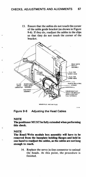
CHECKS, ADJUSTMENTS AND ALIGNMENTS 67
13. Ensure that the cables do not touch the comer of the cable guide bracket (as shown in Figure 9-6). If they do, readjust the cables in the clips so that they do not touch the corner of the bracket.
READ/WRITE MODULE ASSEMBLY
NIIIHt---+-- PLUG FOR LOWER HEAD
PLUG FOR UPPER HEAD
PLASTIC INSULATING
010>"1004---- STICKER
NEWER RlOl AND ANY Rl02
CABLES MUST NOT TOUCH THIS BRACKET WHEN HEADS ARE FULLY EXTENDED
Figure 9-6 Adjusting the Head Cables
NOTE The positioner MUST be fully extended when performing this check.
NOTE The Read/Write module box assembly will have to be removed from the baseplate holding nanges and held in one hand to readjust the cables, as the cables are not long enough to reach.
14. Replace the servo in-line connector to unload the heads. At this point, the procedure is finished.

68 CHECKS, ADJUSTMENTS AND ALIGNMENTS
9.7 READ SIGNAL AMPLITUDE CHECK This procedure checks the amplitude of the read signal in the read amplifier.
A. Required Tools:
I. Oscilloscope with two probes 2a. One DIP clip, one pin-to-pin jumper and one
test lead (alligator clip), or 2b. Two pin-to-pin jumpers and two DIP chips 3. Diagnostic listed in Table 9-2
B. Check:
I. Remove both top cover assemblies. 2. Defeat SKTO, POS SIG and the cover inter
lock (Table 9-1). 3. Place the Read/Write module box assembly
up and out of the way on the carriage assembly.
4. Install cartridge. 5. Depress the LOAD switch. 6. Wait for the heads to load. 7. Disable the servo drive to the carriage by dis
connecting the servo in-line connector. 8a. Version I of DLM: Place Channel A
probe on TP9 (Sector Time). 8b. Version 2 of DLM: Place Channel A
probe on TPII (Sector Time). 8c. Version 3 of DLM: Place Channe'l A
probe on TPII (Sector Time). 9. Place the Channel B oscilloscope probe on
TP2 of the Read/ Write module (Servo Data). 10. Set the oscilloscope to sync internal on Chan
nel A, negative-going, and observe the waveform shown in Figure 9-4.
II. Move the positioner forward until the S I servo burst loses amplitude and finally disappears. This will be the inner guard band area of the disk.
12. Pull the positioner back slowly until the SI servo burst returns. This will be the last data track on the disk (track 255 on an RLOI, track') 511 on an RL02).

CHECKS. ADJUSTMENT AND ALIGNMENTS 69
,oj or In'; I" '
13. Measure and record the peak-to-peak amplitude of the SI burst for both heads (see Table 9-2 to select heads). The minimum allowable amplitude at the innermost track is 500 mv.
14. Reposition the carriage to track 0 by moving the positioner back until S2 disappears (outer guard band) and then forward unty S2 reappears.
15. Measure and record the peak-to-peak amplitude of S I for both heads. The maximum allowable amplitude of the S I burst on track 0 is 2.25 V.
16. Replace either or both heads that do not meet the specification.
NOTE If both heads r.n to meet the specific.tion, it is possible th.t the Re.d/Write module isb.d. Repl.ce the module (see the RLOJ/RL02 T,chnical Mllnutd) and repeat the proc4!dure. If • he.d is replaced, it must be .Ugned (see P.r ..... ph 9.6). The r.di.1 .lignment must .150 be checked (Par.gr.ph 9.5).
9.8' SPINDLE RUNOUT CHECK Excessive runout in the spindle assembly or cartridge can ~ause severe tracking problems for the positioning system. This check will determine whether:
I. Runout exists or does not exist 2. Runont is in the cartridge 3. Runout is in the spindle
A. Required Tools:
I. Oscilloscope with probe and ground leads 2. DIP clip 3. Jumper 4. Several test cartridges
B. Runout Check:
I. Remove both top cover assemblies. 2. ,Place the Read/Write module box assembly up
and out of the way of the carriage assembly. 3. Defeat cover interlock (Table 9-1) .
. 4. Install cartridge. 5. Depress LOAD switch.

70 CHECKS, ADJUSTMENTS AND ALIGNMENTS
NOTE
6. Wait for heads to load onto the pack. 7. Disable servo drive to the carriage by discon
necting the in-line connector (Figure 9-3). 8a. Version I of DLM: Place Channel A oscillo
scope probe on Ell pin 7 (Position Signal) and place Channel A ground on TP7 (Integrator Ground).
8b. Version 2 of DLM: Place Channel A oscilloscope probe on TPl5 (Position Signal) and place Channel A ground on TP5 (Integrator Ground).
8c. Version 3 of DLM: Place Channel A oscilloscope probe on TPl5 (Position Signal) and place Channel A ground on TP5 (Integrator Ground).
9. Set the oscilloscope to sync internal, negative-going, and observe the waveform in Figure 9- 7.
Ideally, the oscilloscope will display a nearly straight line of dots.
POSITION SIGNAL
TIME = 5MSICM VOLTS = 200MVIDIV.
Figure 9-7 Position Signal
CZ·1068
10. The amplitude of the runout should be no greater than 350 mv.
II. If the specification cannot be met, runout exists and another cartridge is needed to determine if the runout exists in the cartridge or the spindle.

CHECKS, ADJUSTMENTS AND ALIGNMENTS 71
12. To confirm a seating problem, re-seat the cartridge and repeat the runout check. If the runout is within specification, the problem has been solved. If the runout is still out of specification, continue with Step 13.
13. Spindle and cartridge are still suspect, so install a second cartridge and repeat check. If runout is now within the specification, the first cartridge is bad. If the runout check fails once more, assume that the spindle bearings are bad and replace the spindle assembly.
9.9 POSITION SIGNAL GAIN CHECK Insufficient amplitude of the Position Signal could result in the carriage not being able to hold itself on track, resulting in read errors and possible seek errors. Too high an amplitude could result in a jitter which, in tum, emits a vibrating-type noise from the carriage that may generate seek timeout errors.
A. Required Tools:
I. Oscilloscope with probe and ground leads 2. One DIP clip, one pin-to-pin jumper
B. Gain Check:
1. Remove both top cover assemblies. 2. Place the Read/Write module box assembly up
and out of the way of the carriage assembly. 3. Defeat SKTO and cover interlock (Table
9-1). 4. Install cartridge. 5. Depress LOAD switch. 6. Wait for heads to load onto the pack. 7. Disable servo drive to the carriage by discon
necting the in-line connector (Figure 9-3). 8a. Version I of DLM: Place Channel A oscillo
scope probe on Ell pin 7 (Position Signal) and place Channel A ground on TP7 (Integrator Ground).
8b. Version 2 of DLM: Place Channel A oscilloscope probe on TPI5 (Position Signal) and place Channel A ground on TP5 (Integrator Ground).
8c. Version 3 of DLM: Place Channel A oscilloscope probe on TPI5 (Position Signal) and place Channel A ground on TP5 (Integrator Ground).

72 CHECKS, ADJUSTMENTS AND ALIGNMENTS
9. Observe the waveform in Figure 9-8 while manually moving the carriage back and forth.
10. Measure the peak-to-peak deviation of the Position Signal amplitude about the ground reference. It should be 3.7 ± 0.7 volts.
GND. REF.
POSITION SIGNAL
00 :'~ • . . • • • •
• . • • • . • • . ••
TIME = 5 MSJDIV. VOLTS = 1 VOLTIDIV.
-.-. ;~. • • .. · : • • • • . · ·i •
• • • • • • • • 0 • •
. . · · · · • • · • · • • • •
Figure 9-8 Position Signal Gain Check Waveform
9.10 TACHOMETER AC NOISE PICK-UP CHECK This procedure checks the amount of noise being picked up by the tachometer. If the noise is excessive, the positioner will have a hard time holding on to a track signal. In this case, the READY light may flicker.
A. Required Tools:
I. Oscilloscope with probe and ground leads 2. DIP clip 3. Jumper
B. Check:
I. Remove both top cover assemblies. 2. Place the Read/Write module up and out of the
way of the carriage assembly. 3. Defeat cover interlock (Table 9-1). 4. Install cartridge. 5. Depress LOAD switch. 6. Wait for heads to load onto the pack.

CHECKS, ADJUSTMENTS AND ALIGNMENTS 73
7. Disable servo drive to the carriage by disconnecting the in-line connector (Figure 9-3).
8. Set the oscilloscope (sync internally) as follows: a. Channel A probe should be on TPI of the
DC Servo module (Summing Amp). b. Channel A ground should be on TPll of the
DC Servo module (Signal Ground). 9. Each drive's summing amplifier output at this
point will look slightly different, but it should be similar to the waveform shown in Figure 9-9.
SUMMING AM~LlFIER OUTPUT
-• & L.
vIA. I" , 1.1. - ".
TIME = 10MS/DIV. VOLTS = 50MV/DIV.
_ . ~ L IJ' r
:"'
Figure 9-9 Summing Amplifier Output
r\. V ~
CZ-,070
10. The signal seen should have a peak-to-peak value of no more than 600 mv.
II. If the signal is out of tolerance, the DC Servo module could be bad or the drive motor may be too noisy. Replace the module, and if that does not solve the problem, replace the drive motor (see the RLOI/ RL02 Disk Drive Technical Manual).

74 CHECKS, ADJUSTMENTS AND ALIGNMENTS
9.11 VELOCITY PROFILE CHECK By causing the positioner to perform an oscillating seek, the velocity profile can be checked for duration, amplitude, and waveshape.
A. Required Tools:
I. Oscilloscope with probe and ground leads 2. Toggle-in oscillating seek program shown in
Chapter 7 3. DIP clip 4. Jumper
B. Check:
I. Remove both top cover assemblies. 2. Install cartridge. 3. Defeat top cover interlock (Table 9-1). 4. Depress LOAD switch. 5. Wait for heads to load onto the pack. 6. Using the oscillating program shown in Chapter
7, cause an oscillating seek from track 0 to track 255 (RLO I) or track 511 (RL02).
7a. Version I of DLM: Place the Channel A oscilloscope probe on TPI2, place the Channel A ground on any of the DLM ground points (TPI through TP6 are ground) and place the external trigger on E38 pin 12 (SIGN FWD).
7b. Version 2 of DLM: Place the Channel A oscilloscope probe on TP8, place the Channel A ground on any of the DLM ground test points (TPI through TP4 are ground) and place the external trigger on E25 pin 12 (SIGN FWD).
7c. Version 3 of DLM: Place the Channel A oscilloscope probe on TP8, place the Channel A ground on any of the DLM ground points (TP 1 through TP4 are ground) and place the external trigger on E25 pin 12 (SIGN FWD).
8. Set the oscilloscope to sync internal, positivegoing, and observe the waveform shown in Figure 9-10.
9. The peak amplitude of the waveform should be between 4.6 and 5.0 volts.
10. The maximum seek time should be between 80 and 86 milliseconds.

CHECKS, ADJUSTMENTS AND ALIGNMENTS 75
TACHOMETER OUTPUT VELOCITY SIGNAL
1- -4.6 TO 5.0 V
J
II ~ ,
i- -4.6 TO 5.0 V I-- 80 TO 86 MS-
r \ H
V I\. / - -J_ -
TIME = 20 MSIDIV. VOLTS = 2VIDIV.
CZ·1071
Figure 9-10 Tachometer Output Velocity Signal
II. Observe the trailing edge of the wavefonn (as indicated by an asterisk in Figure 9-10). There should be a slight "stepping" slope. If the observed slope has spikes in it, the positioner needs replacing as it is not rolling smoothly.
12. If the other specifications (in Steps 9 and 10) cannot be met, the DC Servo module is probably at fault.
9.12 SERVO DRIVE MOTOR CURRENT CHECK One possible cause of seek errors is excessive drive motor current. This check will detennine if there is too much current.
A. Required Tools:
I. Oscilloscope with probes and ground leads 2. Toggle-in oscillating seek program shown in
Chapter 7 3. DIP clip 4. Jumper
B. Check:
I. Remove both top cover assemblies. 2. Defeat top cover interlock (Table 9-1). 3. Install cartridge. 4. Depress LOAD switch. 5. Wait for heads to load onto the pack.
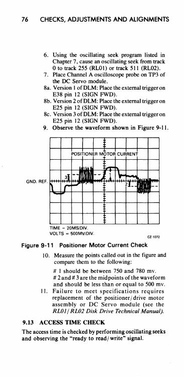
76 CHECKS, ADJUSTMENTS AND ALIGNMENTS
6. Using the oscillating seek program listed in Chapter 7, cause an oscillating seek from track o to track 255 (RL01) or track 511 (RL02).
7. Place Channel A oscilloscope probe on TP3 of the DC Servo module.
8a. Version 1 ofDLM: Place the external trigger on E38 pin 12 (SIGN FWD).
8b. Version 2 of DLM: Place the external trigger on E25 pin 12 (SIGN FWD).
8c. Version 3 of DLM: Place the external trigger on E25 pin 12 (SIGN FWD).
9. Observe the waveform shown in Figure 9-11.
GN D. REF. t++4f+i+~t++tJ
TIME = 20MS/DIV. VOLTS = 500MV/DIV.
CZ·,072
Figure 9-11 Positioner Motor Current Check
10. Measure the points called out in the figure and compare them to the following:
# 1 should be between 750 and 780 mv. # 2 and # 3 are the midpoints ofthe waveform and should be less than or equal to 500 mv.
II. Failure to meet specifications requires replacement of the positioner/drive motor assembly or DC Servo module (see the RLOI/ RL02 Disk Drive Technical Manual).
9.13 ACCESS TIME CHECK
The access time is checked by performing oscillating seeks and observing the "ready to read/ write" signal.

CHECKS, ADJUSTMENTS AND ALIGNMENTS 77
A. Required Tools:
I. Oscilloscope with probes and ground leads 2. Toggle-in oscillating seek program shown in
Chapter 7. 3. DIP clip 4. Jumper
B. Check:
I. Remove both top cover assemblies. 2. Defeat the top cover interlock (Table 9-1). 3. Install cartridge. 4. Depress LOAD switch. 5. Wait for heads to load onto the pack. 6. Using the oscillating seek program shown in
Chapter 7, issue a one track seek.
7a. Version 1 of DLM: Place Channel A oscilloscope prove on E25 pin 12 (Ready to Read/ Write).
7b. Version 2 of DLM: Place Channel A oscilloscope probe on TP 16 (Ready to Read/Write).
7c. Version 3 of DLM: Place Channel A oscilloscope probe on TP 16 (Ready to Read/Write).
8. Observe the waveform depicted in Figure 9-12.
( 17 MS
TIME=2 MS/DIV
VOLTS=2 V/DIV CZ-2063
Figure 9-12 Access Time Check (One Track Seek)

78 CHECKS, ADJUSTMENTS AND ALIGNMENTS
9. Measure the time the "Ready to Read/ Write" signal is low. It should be less than or equal to 17 milliseconds.
10. Issue a seek from track 0 to track 85 (RLOl) or track 170 (RL02) and check to see that" Ready to Read/Write" is low for slightly less than 55 milliseconds. See Figure 9-13.
(55 MS
TIME= 10MS/DIV
VOL TS=2V/DIV
'. "
CZ-2064
Figure 9-13 Access Time Check (85 or 170 Track Seek)
I I. Issue a seek from track 0 to track 255 (RLO I) or track 511 (RL02) and check to see that" Ready to Read/Write" is low for slightly less than 100 milliseconds. See Figure 9-14.
12. If the specifications are not met, the DLM, DC Servo module or the positioner itself could be at fault. (See Paragraph 9.11.)

CHECKS, ADJUSTMENTS AND ALIGNMENTS
(100 MS
TIME=20 MS/DIV
VOL TS=2 V/DIV
79
CZ-2085
Figure 9-14 Access Time Check (255 or 511 Track Seek)


CHAPTER 10 SERVICE TIPS
10.1 LOSS OF +5V SYMPTOM If the unit does not function and the WRITE PROTect lamp is dim, check the +5V.
10.2 LOSS OF +5V CAUSES If the + 5V is missing but the + 8V is present the following causes should be checked (in addition to a defective regulator).
1. Pico fuse on DC Servo Module. 2. Thermal switch on DC Servo Module heat sink. 3. + 5V overvoltage crowbar. 4. Home switch on positioner not closed.
10.3 HEADS RETRACT IMMEDIATELY AFTER LOADING If the heads retract immediately after loading, the head cables may be reversed. Also, the positioner radial alignment may be off. (Positioner radial alignment is described in Paragraph 9.5.)
10.4 LOAD, READY, AND FAULT INDICATORS ALL ON If those three indicators are all on, check the cabling from the controller. See Paragraph 10.5.
10.5 RUI I/O CABLING On RLI 1 systems it is fairly easy to have the I/O cabling reversed because of early documentation errors. The correct method is to have the BC06R red stripe toward the top of the M7762, the BC06R red stripe up at the transition connector, and the BC20] cable pointing down at the transition connector.
10.6 EARLY RLll/RL Vll VECTOR ASSIGNMENT Early RLI l/RL VII Controllers were shipped with a vector address of 330 instead of 160.
81

82 SERVICE TIPS
10.7 ROLE OF CHECKS, ADJUSTMENTS AND ALIGNMENTS IN TROUBLESHOOTING A prerequisite to module swapping as a troubleshooting procedure is to perform one or more of the checks, adjustments and alignments described in Chapter 9. Example 1: Header Not Found and Seek Timeout errors Typical action taken: All modules replaced; head align-
ment checked-problem not solved. Solution: Radial alignment is off due to excessive head
skew. This can be determined and corrected by the Positioner Radial Alignment procedure (Paragraph 9.5).
Example 2: Write Gate errors Typical action taken: All modules replaced; head align
ment checked; radial alignment checked-problem not solved.
Solution: Excessive spindle runout requires replacement of spindle. This can be determined by the Spindle Runout Check (Paragraph 9.8).
Many other problems can be solved by the checks and adjustments described in Chapter 9.
10.8 INTERMITTENT READ CHECK ERRORS There is a new head cable guide designed to reduce the number of intermittent read check errors. See Paragraph 11/2.7.1 of the RW1 / RL02 Technical Manual.

NOTES
83


NOTES
85

NOTES
86

NOTES
87

NOTES
88


![( CNAS) ( p-rp) 2020#-ì+žIIfiU, CNAS-RL02 ( ) fiŽYJ ... · ( CNAS) ( p-rp) 2020#-ì+žIIfiU, CNAS-RL02 ( ) fiŽYJ ( ) fib Y] àÉ ) ákJ , P TP CNAS l: P TP CNAS—RL02 fiŽžJ](https://img.dokumen.tips/doc/110x75/5f8206de7e03494110684092/-cnas-p-rp-2020-iifiu-cnas-rl02-fiyj-cnas-p-rp-2020-iifiu.jpg)