Embed Size (px)
Citation preview

RFID Design Using EM Analysis
James C. Rautio
Sonnet Software, Inc., Syracuse, NY, 13212, USA
Abstract — RFID (Radio Frequency IDentification) tag and
reader antennas can be easily designed using EM analysis software. In this tutorial overview paper, we describe several techniques for designing the key RF portion of both 13.53 MHz and 900 MHz RFID tags and readers. The advantages and disadvantages of various types of EM analysis are reviewed and societal issues related to RFID are raised. Specific examples of RFID design are illustrated by application of a planar EM analysis tool. A unique very broad bandwidth dipole appropriate for 900 MHz RFID is illustrated.
Index Terms — Electromagnetic analysis, Frequency domain analysis, Remote sensing, RFID.
I. INTRODUCTION
FID (Radio Frequency IDentification) is ubiquitous in modern society. As a result, there is increased need for
accurate and fast design of the RF portion of RFID systems. This paper starts with a brief overview of different kinds of EM (electromagnetic) analyses appropriate for RFID design. We then discuss the impact of RFID on society, particularly with regard to privacy issues. The advantages and disadvantages of 13.53 MHz and 900 MHz RFID tags are illustrated, followed by specific design examples. Due to paper length limitations, descriptions are necessarily brief.
II. EM ANALYSIS TYPES
EM analyses appropriate for RFID design fall into two categories based on the type of meshing. Analyses based on volume meshing, Fig. 1, can analyze completely arbitrary structures. There are two basic types: frequency domain and time domain. Frequency domain tools analyze one frequency at a time. Time domain tools calculate the response to an impulse and perform a Fourier transform. Either type is appropriate for complex problems, for example, determining the effect of a tag placed on a curved surface, or quantifying the de-tuning effect of a nearby arbitrary object. A disadvantage of such tools is difficulty of use (requiring capture of 3-D geometries) and analysis times can be long.
The second category is based on surface meshing. In this paper, we focus on EM techniques that mesh only the surface of metal in a circuit. An advantage of this approach is that there is no meshing of dielectric surfaces or volumes. This results in a much faster analysis and simultaneously yields much lower discretization error. However this type of analysis is limited to structures with planar layers of dielectric. Thus a flat RFID tag is easily and quickly analyzed. However,
including the effect of a nearby arbitrary object is not possible.
The dominant error source in a good EM analysis is error due to finite (non-zero) mesh size. In other words, the problem must be discretized and this introduces discretization error. It is important to realize that volume meshing tools have larger discretization error (basically because the entire volume is discretized) than surface meshing tools for planar problems. Thus, if a problem is appropriate for a planar tool, a planar tool should be used.
III. SOCIETAL ISSUES
While this is primarily a technical paper, designers should never blindly work without attention important related issues. Since this is an introductory tutorial, we feel it is appropriate to at least mention some important societal issues. In particular, RFID technology can be improperly used. Even if it is properly used, concern over possible improper use suppresses adoption. For example RFID tags are now present in newly issued passports of several countries. The information that can be read from the passport tag includes all personal information printed in the passport. This assists immigration officers in detecting modified passports. The data in the RFID tag must match the data printed in the passport.
The new passports use 13.53 MHz tags and thus typically must be within a few centimeters of the reader in order to be read. However, it is possible to design a reader (with a large coil and higher power) that can read a tag from considerable distance. A person carrying a passport could have his passport read without his knowledge at any time. In a particularly heinous application, a terrorist could rig a bomb to explode only when it detects the tag of a passport from a citizen of a target country.
R
Fig. 1. A 3-D arbitrary structure (waveguide horn antenna) appropriate for a volume meshing EM analysis (left), and an RF integrated circuit on a carrier appropriate for a surface meshing planar EM analysis (right).
IEEE MTT-S International Microwave Workshop on Wireless Sensing, Local Positioning, and RFID (IMWS 2009 - Croatia)
978-1-4244-5062-6/09/$26.00 ©2009 IEEE
To counter these low probability, but very real threats, passports now use modified covers so that the tag can be read only when the passport is held open. Thus a closed passport provides no indication of its existence to a surreptitious reader. These special covers were not used in the initial RFID passport design. If the RFID designers had actively considered potential societal issues, the special cover design might have been in place from the very beginning.
IV. 13.53 MHZ RFID DESIGN
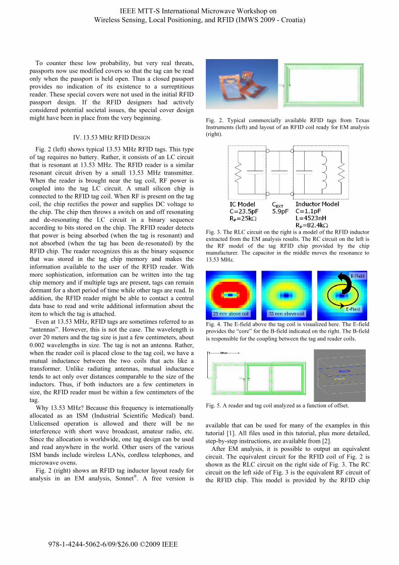
Fig. 2 (left) shows typical 13.53 MHz RFID tags. This type of tag requires no battery. Rather, it consists of an LC circuit that is resonant at 13.53 MHz. The RFID reader is a similar resonant circuit driven by a small 13.53 MHz transmitter. When the reader is brought near the tag coil, RF power is coupled into the tag LC circuit. A small silicon chip is connected to the RFID tag coil. When RF is present on the tag coil, the chip rectifies the power and supplies DC voltage to the chip. The chip then throws a switch on and off resonating and de-resonating the LC circuit in a binary sequence according to bits stored on the chip. The RFID reader detects that power is being absorbed (when the tag is resonant) and not absorbed (when the tag has been de-resonated) by the RFID chip. The reader recognizes this as the binary sequence that was stored in the tag chip memory and makes the information available to the user of the RFID reader. With more sophistication, information can be written into the tag chip memory and if multiple tags are present, tags can remain dormant for a short period of time while other tags are read. In addition, the RFID reader might be able to contact a central data base to read and write additional information about the item to which the tag is attached.
Even at 13.53 MHz, RFID tags are sometimes referred to as “antennas”. However, this is not the case. The wavelength is over 20 meters and the tag size is just a few centimeters, about 0.002 wavelengths in size. The tag is not an antenna. Rather, when the reader coil is placed close to the tag coil, we have a mutual inductance between the two coils that acts like a transformer. Unlike radiating antennas, mutual inductance tends to act only over distances comparable to the size of the inductors. Thus, if both inductors are a few centimeters in size, the RFID reader must be within a few centimeters of the tag.
Why 13.53 MHz? Because this frequency is internationally allocated as an ISM (Industrial Scientific Medical) band. Unlicensed operation is allowed and there will be no interference with short wave broadcast, amateur radio, etc. Since the allocation is worldwide, one tag design can be used and read anywhere in the world. Other users of the various ISM bands include wireless LANs, cordless telephones, and microwave ovens.
Fig. 2 (right) shows an RFID tag inductor layout ready for analysis in an EM analysis, Sonnet®. A free version is
available that can be used for many of the examples in this tutorial [1]. All files used in this tutorial, plus more detailed, step-by-step instructions, are available from [2].
After EM analysis, it is possible to output an equivalent circuit. The equivalent circuit for the RFID coil of Fig. 2 is shown as the RLC circuit on the right side of Fig. 3. The RC circuit on the left side of Fig. 3 is the equivalent RF circuit of the RFID chip. This model is provided by the RFID chip
Fig. 2. Typical commercially available RFID tags from Texas Instruments (left) and layout of an RFID coil ready for EM analysis (right).
Fig. 3. The RLC circuit on the right is a model of the RFID inductor extracted from the EM analysis results. The RC circuit on the left is the RF model of the tag RFID chip provided by the chip manufacturer. The capacitor in the middle moves the resonance to 13.53 MHz.
Fig. 4. The E-field above the tag coil is visualized here. The E-field provides the “core” for the B-field indicated on the right. The B-field is responsible for the coupling between the tag and reader coils.
Fig. 5. A reader and tag coil analyzed as a function of offset.
IEEE MTT-S International Microwave Workshop on Wireless Sensing, Local Positioning, and RFID (IMWS 2009 - Croatia)
978-1-4244-5062-6/09/$26.00 ©2009 IEEE

vendor. In this case, an extra 5.9 pF is required in order to resonate the tag at 13.53 MHz. This extra capacitance is provided by the RFID designer. Such capacitors can be seen in the RFID tags of Fig. 2 (left).
Fig. 4 shows the EM analysis calculated electric field at 25 mm and 35 mm above the RFID coil. Typically, surface meshing planar EM analyses do not calculate full volumetric fields. Volume meshing tools are best for that purpose. However, electric fields parallel to the surface of the substrate are easily calculated by surface meshing tools and are shown here. The location of the magnetic (B, or H) field can be inferred from the electric field because it “curls” around the electric field, as shown in Fig. 4 (right).
So how much coupling is there between resonant reader and tag coils? This is calculated as a function of the offset distance between the reader and tag coils as shown in Fig. 5. We would expect that with the reader coil exactly over the tag coil, we would have maximum coupling. As the reader coil is offset from the tag coil, coupling should decrease.
In fact, this is not true. In Fig. 6, we plot the magnitude of one of the Z-parameters (Z21) as determined by the EM analysis. The magnitude of Z21 corresponds to the number of mV induced in the tag coil for every mA of current in the reader coil. In this case, when the two coils exactly overlap, the voltage induced in the tag coil (Fig. 6, 0 mm offset curve) is actually less at the center frequency. This is because the coils are so tightly coupled that the resonance actually splits into two resonances, one below and the other above the desired resonant frequency. However, there is still plenty of
voltage to operate the RFID chip. When there is no overlap between the coils (80 mm offset), the induced voltage drops rapidly. The induced voltage is reduced by resistive loss in the RFID coil. Thus coil loss should typically be kept as low as possible, consistent with cost and size constraints. However, keep in mind that reduced coil loss increases Q and narrows the RFID tag bandwidth. This makes the tag more susceptible to being de-tuned by unexpected nearby objects.
V. 900 MHZ RFID DESIGN
Fig. 7 shows a typical commercial 900 MHz RFID tag. Now we really do have an antenna, specifically, a half wave length dipole. In this case, the dipole antenna also includes a matching network and capacitive loading making the dipole shorter. Some commercial 900 MHz RFID tags use fanciful “artistic” layouts. The artistic aspect of such tags serves little or no engineering purpose and could conceivably compromise design goals.
The 900 MHz ISM band has a major problem. Different regions of the world use different portions of the band. Thus a
Fig. 6. Z21 magnitude is the number of mV induced in the tag coil forevery mA of current in the reader coil as determined by the EManalysis.
Fig. 7. Typical commercial 900 MHz RFID tag is a half wavelengthdipole with a matching network.
Fig. 8. The simplified half wavelength dipole used for EM analysis. It is repeatedly and automatically EM analyzed for a range of values of “Length”.
Fig. 9. Of the range of lengths analyzed for the dipole of Fig. 8, a length of 13.6 cm is resonant at the desired 954 MHz. The magnitude of S11 (reflection coefficient) is plotted.
IEEE MTT-S International Microwave Workshop on Wireless Sensing, Local Positioning, and RFID (IMWS 2009 - Croatia)
978-1-4244-5062-6/09/$26.00 ©2009 IEEE

reader must be custom set to a frequency in the band for the region in which it is to be used. In addition a tag must be sensitive to a broad band of potential frequencies. This can be difficult. The advantage of RFID at 900 MHz is that typical read distances are up to 10 m. This is because at 900 MHz, we have a true antenna and true radiation that can propagate over some distance. This means an entire pallet of tagged merchandise can be read by simply standing next to the pallet. On the other hand, the societal privacy issues discussed above could be important, depending on the tag’s purpose.
For this tutorial, the simplified dipole of Fig. 8 is EM analyzed. Since we are not sure of the exact length required, the length of the dipole is set as a parameter. The EM analysis is then set up to automatically analyze the dipole over an entire range of values for the length parameter. We then select the result that yields the desired center frequency, Fig. 9. In this case we select 13.6 cm for a resonant frequency of 954 MHz. This resonant frequency is near the upper end of the ISM band in Region 2 (the Americas). We chose a higher frequency because unexpected nearby objects are most likely to lower the resonant frequency of the antenna.
VI. A BROAD BAND 900 MHZ RFID ANTENNA
The dipole of Fig. 8 and 9 has a bandwidth of 100 MHz. This is not enough to cover all the worldwide 900 MHz ISM bands, even if there were no nearby unexpected objects to de-tune the antenna. Thus, it is highly desirable to increase the bandwidth of the antenna. Because the time required for EM analysis of this, and all antennas considered in this paper, is just a few seconds, it is possible to quickly evaluate a very wide range of potential designs. One such design is shown in Fig. 10. It is similar to the simplest possible log periodic antenna, thus we call it a “quasi-log periodic” antenna [3].
Notice that there are two dimensional parameters in the dipole of Fig. 10. To analyze a wide range of antenna designs, the EM analysis was set up to automatically sweep both parameters over a wide range. A full EM analysis was performed for each combination of parameter values. The EM analysis is so fast, the entire sweep completes quickly. One set
of results is shown in Fig. 11. The highlighted curve is for the indicated dimensions and provides a bandwidth of 320 MHz.
Fig. 11 is plotted for a normalizing impedance of 50 Ohms. If the 900 MHz RFID chip being used is designed for a different impedance, then simply re-plot the data for the desired input impedance. A similar optimal response will be obtained, but the antenna dimensions will be different. Thus, by simply selecting different antenna dimensions, the designer can eliminate the need for a special matching network.
Further analysis, not reported here, investigates the de-tuning effect of a 1 cm glass plate and a conducting plate being moved close to the tag. The glass plate has minimal effect, while the conducting plate has an immediate and strong de-tuning effect.
VII. CONCLUSION
The wide spread use of RFID has resulted in significant need for knowledge of RFID design techniques. Both volume meshing and surface meshing EM analysis techniques are important with complimentary advantages and disadvantages. Several design examples are described using surface meshing for 13.53 MHz and 900 MHz RFID tags. A technique for designing very broad band width dipoles for 900 MHz RFID is illustrated.
REFERENCES
[1] http://sonnetsoftware.com/products/lite/. [2] http://sonnetsoftware.com/resources/. [3] H. T. Hsu, J. C. Rautio, and S. W. Chang, “Novel planar
wideband onmi-directional log-periodic antenna,” Asia Pacific Microwave Conference Proceedings, Dec. 2005.
Fig. 11. A portion of the results for the quasi-log periodic antenna. The selected dimensions yield a bandwidth of 320 MHz. Reflection coefficient (S11) is plotted.
Fig. 10. The quasi-log periodic antenna with two dimensional parameters. The EM analysis was set up for repeated EM analysis of this antenna for many different values of the parameters covering a wide range.
IEEE MTT-S International Microwave Workshop on Wireless Sensing, Local Positioning, and RFID (IMWS 2009 - Croatia)
978-1-4244-5062-6/09/$26.00 ©2009 IEEE