Embed Size (px)
Citation preview

April 201
Review of Lower Thames Crossing Options: Output 2 Design & Costing Report
Prepared by: ....................................................... Checked by: .................................................................Richard Lyon Ian BurrowsAssociate Director Regional Director
Approved by: .......................................................Paul HansonRegional Director
Review of Lower Thames Crossing Options: Output 2 Design & Costing Report
Rev No Comments Checked by
Approved by
Date
8 Published IB PH 25-04-137 Draft Final Version IB PH 18-04-136 Draft Final version including client comments CLB/ RL PH 22-03-135 Revised Draft version 2 IB PH 08-02-134 Revised Draft version 1 IB PH 13-12-123 Revised chapters 1 and 2 IB PH 14-09-122 Second draft issue with cost information JW PH 17-08-121 First draft issue; excludes cost and risk information JW IB 20-07-12
Saxon House, 27 Duke Street, Chelmsford, Essex, CM1 1HTTelephone: 01245 771200 Website: http://www.aecom.com
Job No 60249197 Reference Output 2: Design and Costing Report Date Created April 2013
This document has been prepared by AECOM Limited for the sole use of our client (the “Client”) and in accordance with generally accepted consultancy principles, the budget for fees and the terms of reference agreed between AECOM Limited and the Client. Any information provided by third parties and referred to herein has not been checked or verified by AECOM Limited, unless otherwise expressly stated in the document. No third party may rely upon this document without the prior and express written agreement of AECOM Limited.
Although this report was commissioned by the Department for Transport (DfT), the findings and recommendations are those of the authors and do not necessarily represent the views of the DfT. The information or guidance in this document (including third party information, products and services), is provided by DfT on an 'as is' basis, without any representation or endorsement made and without warranty of any kind whether express or implied.

Executive Summary....................................................................................................................................................
1 Introduction.................................................................................................................................................... 01.1 Purpose of Report................................................................................................................................ 01.2 Overall Approach................................................................................................................................. 01.3 Report Structure................................................................................................................................... 0
2 Approach to Identifying Constraints............................................................................................................02.1 Introduction.......................................................................................................................................... 02.2 Environmental Constraints................................................................................................................... 02.3 Planning Constraints............................................................................................................................ 02.4 Engineering Design Constraints...........................................................................................................0
3 Approach to Design....................................................................................................................................... 03.1 Introduction.......................................................................................................................................... 03.2 General Design Requirements.............................................................................................................03.3 Design Process.................................................................................................................................... 03.4 Road Capacity Design Assumptions....................................................................................................03.5 Design Assumptions for Roads and their Compliance with Standards.................................................03.6 Conceptual Design Assumptions for Bridge Structures........................................................................03.7 Conceptual Design Assumptions for Tunnel Structures.......................................................................03.8 Other Design Issues............................................................................................................................. 0
4 Approach to Estimating Capital Costs.........................................................................................................04.1 Introduction.......................................................................................................................................... 04.2 Overall Approach................................................................................................................................. 04.3 Composition of Capital Costs...............................................................................................................04.4 Methodology used to Estimate Construction Costs..............................................................................04.5 Methodology used to Estimate Options and Development Phase Costs.............................................04.6 Approach to Quantifying the Cost of Risk.............................................................................................04.7 Inflation, Programme Risk and Range Narrowing................................................................................04.8 Methodology used to Estimate Crossing Structures providing an additional three lanes in each
direction................................................................................................................................................ 0
5 Option A.......................................................................................................................................................... 05.1 Introduction.......................................................................................................................................... 05.2 Existing Crossing Layout and Associated Junctions............................................................................05.3 Assumed Illustrative Route................................................................................................................... 05.4 Review of Environmental Constraints..................................................................................................05.5 Review of Planning Constraints (see Figure 8a and Appendix 4)........................................................05.6 Review of Engineering Design Constraints..........................................................................................05.7 Assumed Road and Crossing Structures.............................................................................................05.8 Buildability............................................................................................................................................ 05.9 Deliverability......................................................................................................................................... 05.10 Estimated Costs................................................................................................................................... 0
6 Option B.......................................................................................................................................................... 06.1 Introduction.......................................................................................................................................... 0
Table of Contents Volume 1

6.2 Assumed Illustrative Route................................................................................................................... 06.3 Review of Environmental Constraints..................................................................................................06.4 Review of Planning Constraints (see Figure 8a)..................................................................................06.5 Review of Engineering Design Constraints..........................................................................................06.6 Assumed Road and Crossing Structures.............................................................................................06.7 Buildability............................................................................................................................................ 06.8 Deliverability......................................................................................................................................... 06.9 Estimated Costs................................................................................................................................... 0
7 Option C.......................................................................................................................................................... 07.1 Introduction.......................................................................................................................................... 07.2 Assumed Illustrative Route................................................................................................................... 07.3 Review of Environmental Constraints..................................................................................................07.4 Review of Planning Constraints (see Figures 8b and 8c).....................................................................07.5 Review of Engineering Design Constraints..........................................................................................07.6 Assumed Road and Crossing Structures.............................................................................................07.7 Buildability............................................................................................................................................ 07.8 Deliverability......................................................................................................................................... 07.9 Estimated Costs................................................................................................................................... 0
8 Option Cvariant................................................................................................................................................... 08.1 Introduction.......................................................................................................................................... 08.2 Existing Layout and Junctions..............................................................................................................08.3 Assumed Illustrative Route Improvement.............................................................................................08.4 Review of Environmental Constraints..................................................................................................08.5 Review of Planning Constraints (see Figure 8d)..................................................................................08.6 Review of Engineering Design Constraints..........................................................................................08.7 Assumed Road Layout......................................................................................................................... 08.8 Buildability............................................................................................................................................ 08.9 Deliverability......................................................................................................................................... 08.10 Estimated Costs................................................................................................................................... 0
9 Summary and Conclusions........................................................................................................................... 09.1 Overview.............................................................................................................................................. 09.2 Costs.................................................................................................................................................... 09.3 Type of Structure.................................................................................................................................. 09.4 Option A............................................................................................................................................... 09.5 Option B............................................................................................................................................... 09.6 Option C............................................................................................................................................... 09.7 Option Cvariant......................................................................................................................................... 0
Appendix A – Figures (see separate volume).........................................................................................................0Appendix B – Detailed Cost Information.................................................................................................................. 0Appendix C – Contraints Tables............................................................................................................................... 0Appendix D – Planning Data...................................................................................................................................... 0
Table 3.1: Indicative Forecast Traffic Flows for Options B and C in Passenger Car Units in 2041..............................0Table 4.1: Capital Cost Definitions and Assumptions...................................................................................................0Table 4.2: Inflation with respect to calendar year.........................................................................................................0Table 5.1: Option A: Most likely estimated capital costs for new four lane crossing structures and link roads.............0

Table 5.2: Option A: Total cost ranges for a new four lane Crossing...........................................................................0Table 5.3: Option A: Most likely estimated capital costs for a new six lane crossing structures...................................0Table 6.1: Option B: Most likely estimated capital costs for new crossing structures and link roads with two lanes in
each direction................................................................................................................................................... 0Table 6.2: Option B: Total cost ranges for new crossings with two lanes in each direction..........................................0Table 6.3: Option B: Most likely estimated capital costs for new crossing structures with three lanes in each direction
......................................................................................................................................................................... 0Table 7.1: Option C: Most likely estimated capital costs for new crossing structures and link roads with two lanes in
each direction................................................................................................................................................... 0Table 7.2: Option C: Total cost ranges for new crossings with two lanes in each direction..........................................0Table 7.3: Option C: Most likely estimated capital costs for new crossing structures with three lanes in each direction
......................................................................................................................................................................... 0Table 8.1: Option Cvariant Estimated Costs Ranges...................................................................................................0Table 9.1: Most likely estimated capital costs for new crossing structures and link roads providing an additional two
lanes in each direction..................................................................................................................................... 0Table 9.2: Most likely estimated capital costs for new crossing structures providing an additional three lanes in each
direction........................................................................................................................................................... 0Table B1.1: Cost estimates for Option A...................................................................................................................... 0Table B1.2: Cost estimates for Option B...................................................................................................................... 0Table B1.3: Cost estimates for Option C...................................................................................................................... 0Table B1.4: Cost estimate for Option Cvariant.............................................................................................................0Table C1.1: Option A Contraints................................................................................................................................... 0Table C1.2: Option B Constraints................................................................................................................................. 0Table C1.3: Option C Constraints................................................................................................................................. 0
Figure 4.1: HA Project Control Framework Phases and Stages...................................................................................0Figure 5.1: Option A – Assumed North Layout.............................................................................................................0Figure 5.2: Option A: Assumed South Layout..............................................................................................................0Figure 9.1: River Thames Crossing Options................................................................................................................0
AECOM Lower Thames Crossing Options Review iReport on Design and Costs
Context and Objectives
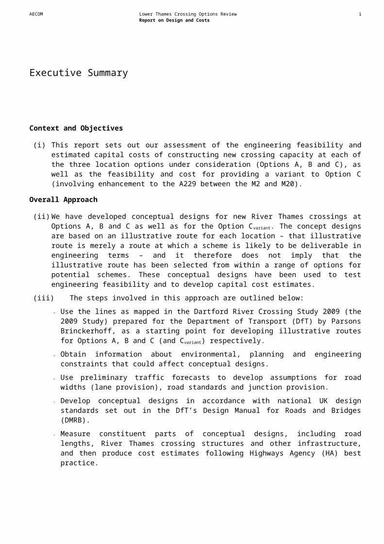
(i) This report sets out our assessment of the engineering feasibility and estimated capital costs of constructing new crossing capacity at each of the three location options under consideration (Options A, B and C), as well as the feasibility and cost for providing a variant to Option C (involving enhancement to the A229 between the M2 and M20).
Overall Approach
(ii) We have developed conceptual designs for new River Thames crossings at Options A, B and C as well as for the Option Cvariant. The concept designs are based on an illustrative route for each location – that illustrative route is merely a route at which a scheme is likely to be deliverable in engineering terms – and it therefore does not imply that the illustrative route has been selected from within a range of options for potential schemes. These conceptual designs have been used to test engineering feasibility and to develop capital cost estimates.
(iii) The steps involved in this approach are outlined below:
- Use the lines as mapped in the Dartford River Crossing Study 2009 (the 2009 Study) prepared for the Department of Transport (DfT) by Parsons Brinckerhoff, as a starting point for developing illustrative routes for Options A, B and C (and Cvariant) respectively.
- Obtain information about environmental, planning and engineering constraints that could affect conceptual designs.
- Use preliminary traffic forecasts to develop assumptions for road widths (lane provision), road standards and junction provision.
- Develop conceptual designs in accordance with national UK design standards set out in the DfT’s Design Manual for Roads and Bridges (DMRB).
- Measure constituent parts of conceptual designs, including road lengths, River Thames crossing structures and other infrastructure, and then produce cost estimates following Highways Agency (HA) best practice.
Approach to Identifying Constraints
(iv) The first stage of our work was to review constraints for the options. This work drew on existing data sources in respect of air quality, biodiversity, heritage, landscape/townscape, noise and water environment to identify environmental constraints. Information on planned development sites was assimilated from local authority planning documents. We obtained information from the Port of London Authority (PLA) and Network Rail, respectively, about river navigation constraints and rail infrastructure, including the High Speed 1 (HS1) rail line. Geotechnical data on ground conditions was sourced from web based data. We also contacted and obtained data from major public utilities on the location of their infrastructure.
Executive Summary

AECOM Lower Thames Crossing Options Review iiReport on Design and Costs
Approach to Design
(v) We developed conceptual designs as a basis for assessing the feasibility of a new crossing at each location option and to estimate capital costs.
(vi) Designs were developed in accordance with the standards set out in the DMRB. However, for the strategic purposes of the study, it was not necessary, and we did not seek, to develop detailed designs or plans that would provide precise proposals for the alignment of a new crossing or associated link roads.
(vii) We judged that there were no significant constraints requiring the illustrative route for a new crossing at Option A assumed in the 2009 Study to be significantly altered. However, we modified the illustrative routes for new crossings at Options B and C detailed in the 2009 Study:
- Option B: We identified a variation to the illustrative route set out in the 2009 Study that followed the Ebbsfleet valley, joining the A2 at Ebbsfleet Junction, rather than traversing Eastern Quarry and joining the A2 at Bean Junction.
- Option C: The illustrative route for Option C was modified to reflect DMRB design standards for conceptual M25 and A13 junctions and to seek to minimise impacts on the Thames Estuary and Marshes Ramsar site
(viii) The charge collection method at the existing Dartford-Thurrock Crossing is planned to change from the existing toll plazas to a free-flow system in 2014. This free flow operation was therefore assumed for the design of the new crossing structures and toll plazas have not been included in designs.
(ix) We considered the feasibility of providing a bridge, an immersed tunnel and a bored tunnel at all three location options.
(x) The conceptual designs assume two additional lanes would be provided in each direction at each location option, informed by preliminary traffic forecasting results. However, in recognition of uncertainty, the importance of safeguarding the resilience of the new crossing and the high cost that would be involved with providing additional crossing capacity at a later date, we have also prepared an estimate of the capital cost involved with providing a further lane (i.e. three additional lanes) in each direction for River Thames crossing structures at each location. Separate designs for crossing structures providing three lanes in each direction have not been produced.
(xi) For the strategic purposes of this study, all conceptual designs for new crossings and related infrastructure at all three location options have been based on standards for all purpose roads.
Approach to Estimating Capital Costs
(xii) We used conceptual designs to produce three point minimum, most likely and maximum cost estimates for crossings providing an additional two lanes in each direction in line with HA best practice.
(xiii) Capital cost estimates are expressed in projected outturn prices, i.e. reflecting expected inflation and based on an assumption that a new crossing would be constructed between 2021 and 2025. We have summarised the costs in terms of:
AECOM Lower Thames Crossing Options Review iiiReport on Design and Costs
- The direct capital cost for the crossing structure; and
- Capital costs for associated roads required to link the structure with the existing road network.
(xiv) Additionally, to show how costs could vary if it were determined more than four lanes of additional capacity on the crossing itself were needed, cost estimates for River Thames crossing structures providing three additional lanes in each direction were produced by applying a factor to the most likely cost estimates for crossing structures providing two additional lanes in each direction. These estimates are also expressed as projected outturn prices. These estimates do not include the cost of providing additional lanes for link roads.
Option A
(xv) A new crossing at Option A would provide additional capacity at the existing Dartford-Thurrock Crossing. We have assumed that a new structure (or structures) at Option A would be provided upstream of the existing bored tunnels, with northbound traffic using the four lanes provided by a new structure(s) plus the existing west bore tunnel. Southbound traffic is assumed to continue to use the QEII Bridge and the existing east bore tunnel1. Our estimates of the most likely capital costs are set out below.
Option A: Most likely estimated capital costs for new four lane crossing structures and link roads
Bridge Immersed Tunnel Bored TunnelCrossing Structure £0.91bn £1.18bn £1.15bnLink Roads £0.34bn £0.42bn £0.43bnTotal £1.25bn £1.60bn £1.57bn
Option A: Most likely estimated capital costs for new six lane crossing structures
Bridge Immersed Tunnel Bored TunnelCrossing Structure £1.20bn £1.51bn £1.81bn
Option B
(xvi) A new crossing at Option B would provide a link between the A2 at Ebbsfleet and the A1089, north of Tilbury. We have assumed that the route of a new crossing at Option B would follow the HS1 rail line on the south side of the River Thames whilst passing close to Swanscombe.
(xvii) A bridge crossing would need to be higher at Option B than Option A due to river navigation requirements.
(xviii) On the north side of the River Thames an extensive bridge approach viaduct would be needed and would affect housing in the east Grays area more significantly than the two tunnel options. Our estimates of the most likely capital costs are set out below.
1 This arrangement would provide two additional lanes in each direction at the existing Dartford-Thurrock Crossing.

AECOM Lower Thames Crossing Options Review ivReport on Design and Costs
Option B: Most likely estimated capital costs for new crossing structures and link roads with two lanes in each direction
Bridge Immersed Tunnel Bored TunnelCrossing structure £1.68bn £1.83bn £1.72bnLink Roads £0.10bn £0.19bn £0.45bnTotal £1.78bn £2.02bn £2.17bn
Option B: Most likely estimated capital costs for new crossing structures with three lanes in each direction
Bridge Immersed Tunnel Bored TunnelCrossing Structure £2.11bn £2.34bn £2.71bn
Option C
(xix) A new crossing at Option C would connect the A2 at Cobham in Kent with the M25 in Essex at a new junction between Junctions 29 and 30. It would also connect with the A128 Orsett Cock Junction on the A13 in Essex. On the south side of the River Thames, the assumed illustrative route has been assumed to be positioned at the western edge of the internationally recognised Thames Estuary and Marshes Ramsar site. Our estimates of the most likely capital costs are set out below.
Option C: Most likely estimated capital costs for new crossing structures and link roads with two lanes in each direction
Bridge Immersed Tunnel Bored TunnelCrossing Structure £1.82bn £1.83bn £1.93bnLink Roads £1.42bn £1.26bn £1.22bnTotal £3.24bn £3.09bn £3.15bn
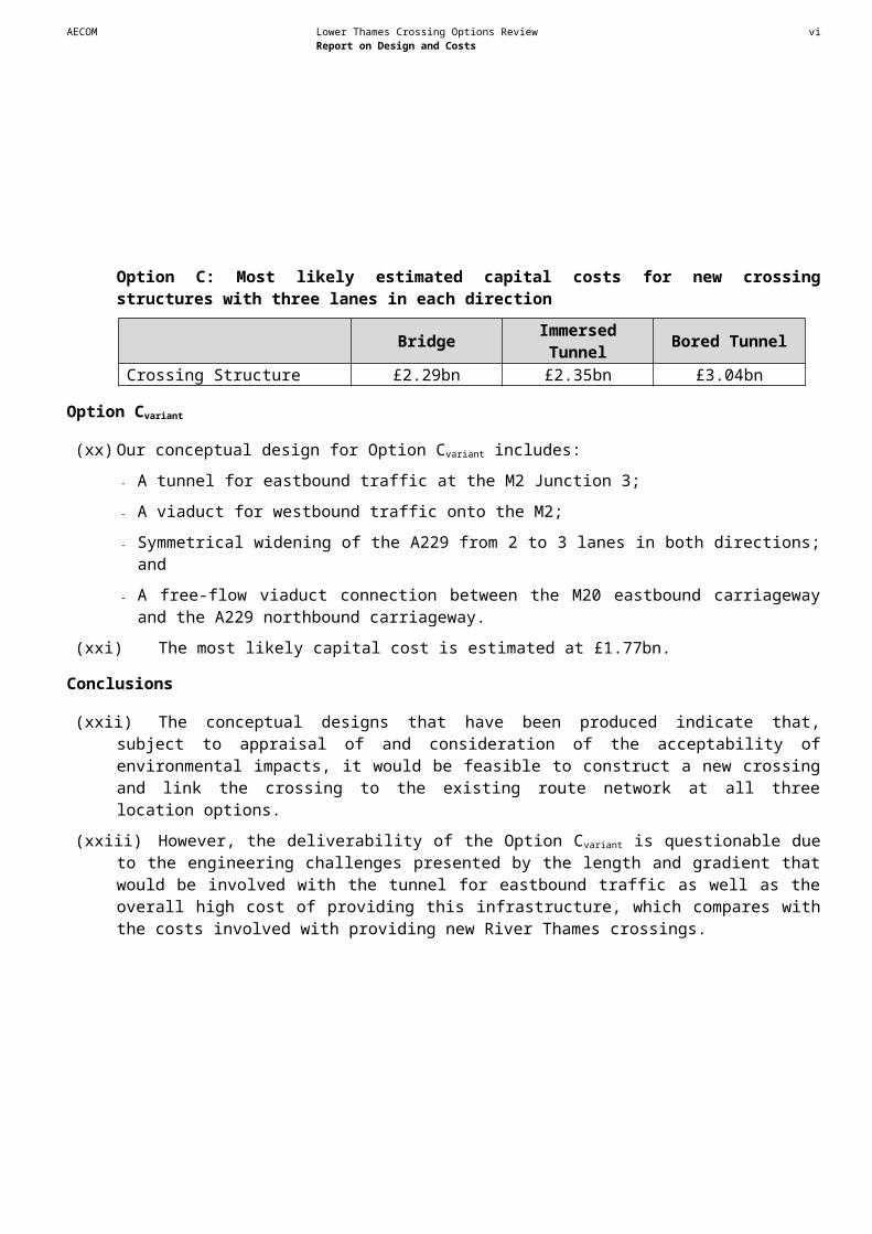
Option C: Most likely estimated capital costs for new crossing structures with three lanes in each direction
Bridge Immersed Tunnel Bored TunnelCrossing Structure £2.29bn £2.35bn £3.04bn
Option Cvariant
(xx) Our conceptual design for Option Cvariant includes:
- A tunnel for eastbound traffic at the M2 Junction 3;
- A viaduct for westbound traffic onto the M2;
- Symmetrical widening of the A229 from 2 to 3 lanes in both directions; and
- A free-flow viaduct connection between the M20 eastbound carriageway and the A229 northbound carriageway.

AECOM Lower Thames Crossing Options Review vReport on Design and Costs
(xxi) The most likely capital cost is estimated at £1.77bn.
Conclusions
(xxii) The conceptual designs that have been produced indicate that, subject to appraisal of and consideration of the acceptability of environmental impacts, it would be feasible to construct a new crossing and link the crossing to the existing route network at all three location options.
(xxiii) However, the deliverability of the Option Cvariant is questionable due to the engineering challenges presented by the length and gradient that would be involved with the tunnel for eastbound traffic as well as the overall high cost of providing this infrastructure, which compares with the costs involved with providing new River Thames crossings.

AECOM Lower Thames Crossing Options Review 6Report on Design and Costs
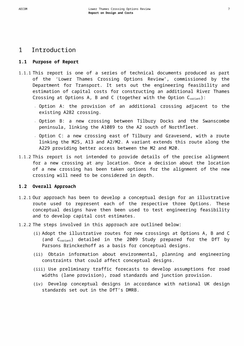
1.1 Purpose of Report
1.1.1 This report is one of a series of technical documents produced as part of the ‘Lower Thames Crossing Options Review’, commissioned by the Department for Transport. It sets out the engineering feasibility and estimation of capital costs for constructing an additional River Thames Crossing at Options A, B and C (together with the Option Cvariant):
- Option A: the provision of an additional crossing adjacent to the existing A282 crossing.
- Option B: a new crossing between Tilbury Docks and the Swanscombe peninsula, linking the A1089 to the A2 south of Northfleet.
- Option C: a new crossing east of Tilbury and Gravesend, with a route linking the M25, A13 and A2/M2. A variant extends this route along the A229 providing better access between the M2 and M20.
1.1.2 This report is not intended to provide details of the precise alignment for a new crossing at any location. Once a decision about the location of a new crossing has been taken options for the alignment of the new crossing will need to be considered in depth.
1.2 Overall Approach
1.2.1 Our approach has been to develop a conceptual design for an illustrative route used to represent each of the respective three Options. These conceptual designs have then been used to test engineering feasibility and to develop capital cost estimates.
1.2.2 The steps involved in this approach are outlined below:
(i) Adopt the illustrative routes for new crossings at Options A, B and C (and Cvariant) detailed in the 2009 Study prepared for the DfT by Parsons Brinckerhoff as a basis for conceptual designs.
(ii) Obtain information about environmental, planning and engineering constraints that could affect conceptual designs.
(iii) Use preliminary traffic forecasts to develop assumptions for road widths (lane provision), road standards and junction provision.
(iv) Develop conceptual designs in accordance with national UK design standards set out in the DfT’s DMRB.
(v) Measure constituent parts of conceptual designs, including road lengths, River Thames crossing structures and other parts, and then produce cost estimates following HA best practice.
1.2.3 This stage of our work has considered capital costs for each Option (i.e. preparation and construction costs). Operating and maintenance costs are considered and reported separately.
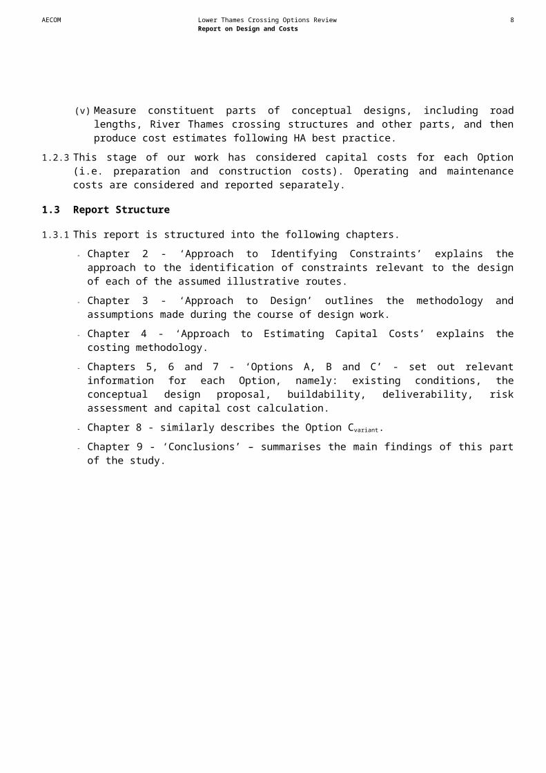
1.3 Report Structure
1.3.1 This report is structured into the following chapters.
- Chapter 2 - ‘Approach to Identifying Constraints’ explains the approach to the identification of constraints relevant to the design of each of the assumed illustrative routes.
1 Introduction

AECOM Lower Thames Crossing Options Review 7Report on Design and Costs
- Chapter 3 - ‘Approach to Design’ outlines the methodology and assumptions made during the course of design work.
- Chapter 4 - ‘Approach to Estimating Capital Costs’ explains the costing methodology.
- Chapters 5, 6 and 7 - ‘Options A, B and C’ - set out relevant information for each Option, namely: existing conditions, the conceptual design proposal, buildability, deliverability, risk assessment and capital cost calculation.
- Chapter 8 - similarly describes the Option Cvariant.
- Chapter 9 - ‘Conclusions’ – summarises the main findings of this part of the study.
AECOM Lower Thames Crossing Options Review 8Report on Design and Costs
1.4 Introduction
1.4.1 This chapter sets out the approach to identifying constraints data obtained to aid the conceptual design of an assumed illustrative route for a new crossing at each location option. The data obtained relate to known environmental, planning and engineering constraints (i.e. factors which might limit the range of route or design options available) and are shown spatially in the Figures contained in Appendix A.
1.4.2 Chapters 5, 6, 7 and 8 explain how these constraints were considered and influenced conceptual designs.
1.5 Environmental Constraints
1.5.1 Known environmental constraints were identified in accordance with the Department for Transport’s Transport Appraisal Guidance (WebTAG - http://www.dft.gov.uk/webtag) within each of the following topic areas:
- Air quality,
- Biodiversity ,
- Heritage of historic resources,
- Landscape / Townscape,
- Noise, and
- Water Environment.
1.5.2 Greenhouse gases, physical fitness and journey ambience are not relevant at this stage of the study.
1.5.3 The identification of environmental constraints was based upon existing information. Detailed surveys and site visits will need to be carried out to develop a detailed design to fully assess environmental impacts. However the major environmental constraints recorded in existing databases provide sufficient information for the strategic scope of this study.
1.5.4 Constraints maps were produced for the topics listed above. The maps are supported by constraints tables, which describe the resource or receptor that could be affected, the potential impact and options for avoiding the constraint or mitigating or compensating for the potential impact. The maps and accompanying tables can be found in Appendices A and C respectively.
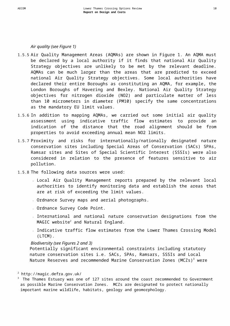
Air quality (see Figure 1)
1.5.5 Air Quality Management Areas (AQMAs) are shown in Figure 1. An AQMA must be declared by a local authority if it finds that national Air Quality Strategy objectives are unlikely to be met by the relevant deadline. AQMAs can be much larger than the areas that are predicted to exceed national Air Quality Strategy objectives. Some local authorities have declared their entire Boroughs as constituting an AQMA, for example, the London Boroughs of Havering and Bexley. National Air Quality Strategy objectives for nitrogen dioxide (NO2) and particulate matter of less than 10 micrometers in diameter (PM10) specify the same concentrations as the mandatory EU limit values.
1 Approach to Identifying Constraints
AECOM Lower Thames Crossing Options Review 9Report on Design and Costs
1.5.6 In addition to mapping AQMAs, we carried out some initial air quality assessment using indicative traffic flow estimates to provide an indication of the distance that the road alignment should be from properties to avoid exceeding annual mean NO2 limits.
1.5.7 Proximity and risks for internationally/nationally designated nature conservation sites including Special Areas of Conservation (SACs) SPAs, Ramsar sites and Sites of Special Scientific Interest (SSSIs) were also considered in relation to the presence of features sensitive to air pollution.
1.5.8 The following data sources were used:
- Local Air Quality Management reports prepared by the relevant local authorities to identify monitoring data and establish the areas that are at risk of exceeding the limit values.
- Ordnance Survey maps and aerial photographs.
- Ordnance Survey Code Point.
- International and national nature conservation designations from the MAGIC website2 and Natural England.
- Indicative traffic flow estimates from the Lower Thames Crossing Model (LTCM).Biodiversity (see Figures 2 and 3)Potentially significant environmental constraints including statutory nature conservation sites i.e. SACs, SPAs, Ramsars, SSSIs and Local Nature Reserves and recommended Marine Conservation Zones (MCZs)3 were mapped (see Figure 2). International designations were identified within 5km, and national designations were identified within 2km, of assumed illustrative routes.
1.5.9 Although not a formal nature conservation designation, Ancient Woodland is a potentially significant environmental constraint since it is difficult to replace and was therefore mapped (see Figure 2).
1.5.10 Biodiversity Action Plan habitats were also mapped (see Figure 3). These were used together with the statutory nature conservation sites on Figure 2 to identify where a particular protected species could be present.
1.5.11 The following data sources were used:
- Information from the MAGIC website and Nature on the Map4.
- K-LIS (Kent Landscape Information System5)
1.5.12 The Greater Thames Marshes Nature Improvement Area (NIA) covers nearly 50,000ha of estuarine marshland in South East England, stretching from East London to Whitstable in Kent and Southend in Essex. However, Natural England has confirmed that no boundary is available for this NIA and it has not therefore been mapped as a constraint. Since the NIA covers a large area, it is not considered a differentiator between the options at this stage.
1.5.13 The Thames Estuary was one of 127 sites around the coast recommended to Government as possible Marine Conservation Zones. The Government has proposed to designated 31 sites as
2 http://magic.defra.gov.uk/3 The Thames Estuary was one of 127 sites around the coast recommended to Government as possible Marine
Conservation Zones. MCZs are designated to protect nationally important marine wildlife, habitats, geology and geomorphology.
4 http://www.natureonthemap.naturalengland.org.uk/5 http://www.kent.gov.uk/klis/home.htm
AECOM Lower Thames Crossing Options Review 10Report on Design and Costs
Marine Conservation Zones, this does not include the Thames Estuary. Further designations will follow in tranche 2.
1.5.14 There are a number of non-statutory sites within 1km of the assumed illustrative routes for new crossings at Options A, B and C. These include Local Wildlife Sites and Royal Society for the Protection of Birds reserves. Many of these sites are combined with statutorily designated sites and therefore share the same footprint (and impact). Such non-statutory sites have not therefore been mapped specifically as part of the constraints identification exercise. Heritage of historic resources (see Figure 4)
1.5.15 Potentially significant constraints including Scheduled Monuments, Registered Parks and Gardens, Listed Buildings, Conservation Areas and non-designated archaeological and built heritage sites were mapped (see Figure 4). There are no Registered Battlefields within 500m of the assumed illustrative routes and therefore these were not mapped.
1.5.16 Data were collected for known heritage sites 500m either side of assumed illustrative routes. A consideration of the broad nature and pattern of constraints revealed that there was an historical tapestry across each of Options A, B, C and Option Cvariant (widening the A229 between the M2 and M20). Scheduled Monuments, Registered Parks and Gardens and Conservation Areas within 500m of the assumed illustrative routes were identified.
1.5.17 Given that it is not the objective of this study to identify a specific alignment for a new crossing, we selected a 100m corridor (50m either side of the assumed illustrative route for new crossings at each location), and identified the non-designated heritage assets of potential major significance within them.
1.5.18 The following data sources were used:
- Data from Kent and Essex Historic Environment Records as appropriate.
- Data from National Monuments Record.
- English Heritage Rapid Coastal Assessment Survey for the South East.
- Online sources including MAGIC and the National Heritage list.Landscape / Townscape (see Figure 5)
1.5.19 Potentially significant environmental constraints including the Kent Downs Area of Outstanding Natural Beauty (AONB), Cobham Hall Registered Park and Garden and other designated relevant landscape, townscape and cultural heritage assets were mapped, including Conservation Areas, Listed Buildings, Scheduled Monuments and Ancient Woodland.
1.5.20 The locations of potentially sensitive visual receptors including residential properties and recreational areas or routes were also identified.
1.5.21 The following data sources were used:
- Ordnance Survey maps and aerial photographs,
- Online data including the MAGIC website to identify landscape designations and other designated sites,
- Relevant Kent and Essex Historic Landscape Characterisation data, and
- Relevant Local Planning Authority data.Noise (see Figure 6)
1.5.22 As required by the Environmental Noise (England) Regulations 2006, Defra has produced strategic noise maps for major roads, which have more than six million vehicle passages a year

AECOM Lower Thames Crossing Options Review 11Report on Design and Costs
and agglomerations with a population of more than 250,000 and a defined population density. Noise Action Plans have been produced for these roads6 and agglomerations, including the London Agglomeration7, which identify “Important Areas”. These are the areas most affected by noise from roads and are shown on the map at Figure 6.
1.5.23 In addition, we also carried out some initial noise calculations using indicative traffic flow estimates to provide an indication of the distance that the road alignment should be from sensitive receptors (such as residential properties, schools and hospitals) to avoid significant noise impacts.
1.5.24 The following data sources were used:
- Ordnance Survey maps,
- Ordnance Survey Code Point,
- Noise Action Planning Important Areas, and
- Indicative traffic flow estimates from the Model Capability Report produced in the first stage of this review.
Water Environment (see Figure 7)
1.5.25 Surface water features, including watercourses/ culverted watercourses, ponds and spring locations were mapped together with groundwater Source Protection Zones (SPZs).
1.5.26 Environment Agency flood zones and flood defences were also mapped and were used to assess the likely significant flood risk constraints associated with fluvial and tidal flooding. Flood risk from any source was not mapped at this stage unless identified in the Environment Agency or local authority source data.
1.5.27 The following data sources were used:
- Information on nationally and internationally designated sites from the MAGIC website and Nature on the Map8.
- Information obtained from the Environment Agency including flood maps, the Thames Estuary 2100 Flood Risk Management Plan, EU designated fisheries, SPZs, and details of existing flood defences.
- Local authority Strategic Flood Risk Assessments.
1.6 Planning Constraints
1.6.1 We carried out a search for planned developments in the area that could act as constraints to a new River Thames crossing. Details sought included the location, land-take (if known), land use class, quantum of development and timescale for delivery/likelihood of implementation. Where timescale information was available the information was used to provide a view on the sites that might be developed during the next 10-15 years.
1.6.2 The committed Eastern Quarry development site was noted as a major constraint to Option B.
1.6.3 Potential constraints are shown in Figures 8a to 8d.
6 (2010) Defra. Noise Action Plan, Major Roads (outside first round agglomerations), Environmental Noise (England) Regulations 2006, as amended. Adopted by Secretary of State for Environment, Food and Rural Affairs 15 March 2010.7 (2010) Defra. Noise Action Plan, London Agglomeration, Environmental Noise (England) Regulations 2006, as amended. Adopted by Secretary of State for Environment, Food and Rural Affairs 15 March 2010.8 http://www.natureonthemap.naturalengland.org.uk/
AECOM Lower Thames Crossing Options Review 12Report on Design and Costs
1.6.4 Information was obtained from local planning authority planning documents, including Core Strategy development plans and other relevant evidence base documents published by the following local authorities:
- Dartford Borough Council (Option A, Option B);
- Thurrock Council (Option A, Option B, Option C);
- Havering Borough Council (Option C);
- Gravesham Borough Council (Option C);
- Medway Council (Option C, Option Cvariant (M2-M20 link));
- Tonbridge and Malling Borough Council (Option Cvariant (M2-M20 link)); and
- Maidstone Borough Council (Option Cvariant (M2-M20 link)).
1.6.5 We also reviewed areas designated as Green Belt within the local authority areas listed above to determine the likely impact on Green Belt associated with new crossings at Options A, B and C.
1.7 Engineering Design Constraints
Navigation
1.7.1 Navigational clearance requirements have been provided by the PLA. These vary between Options A, B and C, reflecting the types of shipping activity at each location.
1.7.2 A minimum clearance is needed to enable shipping to pass beneath bridge structures. This is defined in terms of the height and width between bridge piers required for safe navigation. The vertical clearance, or air draught, is defined during the time of high river - “Mean High Water Springs”. The air draught requirements provided by the PLA apply across the full navigable width of the River Thames and have been set at:
- 54.1m for Option A (same as QE2 bridge); and
- 70m for Options B and C.
1.7.3 The minimum width required between bridge piers has been defined using navigation charts provided by the PLA.
1.7.4 The PLA has advised that the upper surface of an immersed tunnel would need to be below the existing river bed. There are no navigational constraints associated with a bored tunnel.Rail
1.7.5 Network Rail has supplied information on the rail lines on the Essex and Kent sides of the River Thames. On the Kent side, the HS1 rail line affects Options B and C, as well as the Option Cvariant. Topographical mapping and aerial surveys were used to establish the extents and details of surface rail lines. Information on the position and depth of the tunnels was obtained from Network Rail.
1.7.6 Network Rail design guidance9 specifies horizontal and vertical clearances required for new infrastructure. Allowances for safe distances between new and existing structures and constraints that could affect the potential new routes are discussed in Chapters 5-8.
9 Network Rail documents: NR/L2/TRK/2049 Track Design Handbook & GC/RT5212 Requirements for defining and maintaining clearances

AECOM Lower Thames Crossing Options Review 13Report on Design and Costs
Roads
1.7.7 Information on roads was obtained from Ordnance Survey maps and aerial surveys. The maps showed the relative importance of each of the roads. A digital ground model was used to provide details of road levels.
Utilities/Services
1.7.8 Enquiries were made to each of the main utility companies to determine the position of important, or strategic, equipment. Important equipment included high voltage overhead electricity power lines, as well as gas and oil pipelines. Ground Conditions/Geotechnics (see Figure 8e)
1.7.9 Information on the ground conditions that apply at the areas affected by the assumed illustrative routes for new crossings has been obtained from the British Geological Survey database10 and from published geological maps.
1.7.10 In addition, the extent of soft, and potentially contaminated, ground in Landfill Sites has been identified using the Environment Agency’s web based database11. Landfill Constraints are shown in Figure 8e.
10 http://www.bgs.ac.uk/products/onshore/SOBI.html11 http://maps.environment-agency.gov.uk/wiyby/wiybyController?ep=maptopics&lang=_e
AECOM Lower Thames Crossing Options Review 14Report on Design and Costs
1.8 Introduction
1.8.1 This chapter introduces the methodology applied to the engineering design work undertaken and describes generic issues.
1.8.2 The scope of design work carried out is explained in Section 1.9 and the design process we adopted is outlined in Section 1.10. Sections 1.11 and 1.12 discuss the capacity and overall design standards assumed. The remaining sections of this chapter introduce specific design assumptions.
1.9 General Design Requirements
1.9.1 The purpose of our conceptual designs was to provide a structured basis from which to:
- Produce cost estimates;
- Test buildability and deliverability; and
- Appraise environmental impacts (reported separately).3.2.2 As set out in the Introduction to this report, conceptual designs are not intended to provide details
of the precise alignment for a new crossing at any location. Once a decision about the location of a new crossing has been taken options for the alignment of the new crossing will need to be considered in depth.
3.2.3 Conceptual designs were developed to the level of accuracy identified as proportionate to the needs of the study as follows:
- Assumed illustrative routes were made as simple as possible;
- Clearances for the main river Thames crossing structures complied with navigation requirements;
- Bridges over or under existing roads were identified together with an outline assumed illustrative route for any diversion to these roads needed;
- Interchanges with major roads were designed sufficiently to show how they would operate in accordance with design standards; and
- Due account was taken of other engineering constraints such as rail lines and major utilities.
3.2.4 We have not, generally, sought to refine the illustrative routes for new crossings detailed in the 2009 Study except in relation to the following:
- Areas where the impacts associated with a new crossing would have strategic importance, specifically the scale of reduction in development land available should the Option B route cross the Eastern Quarry development site;
- Junction design requirements set out in the DMRB; and
- Minimising the impact of a new crossing at location Option C on the Thames Estuary and Marshes Ramsar site.
2 Approach to Design
AECOM Lower Thames Crossing Options Review 15Report on Design and Costs
1.10 Design Process
1.10.1 The process used to develop conceptual designs from the initial illustrative routes shown in the 2009 Study followed a number of stages, as detailed below.
(i) Data and Constraints Compilation
1.10.2 We compiled 3D digital mapping, constraints data and other engineering data to provide a platform for the conceptual design development.
(ii) Traffic capacity and road standards
1.10.3 Initial indicative traffic forecasts were used to determine minimum road capacity requirements. Consideration was also given to road design standards; i.e. whether to assume a motorway or an all-purpose road.
(iii) Development of River Thames Crossing and approach road alignments
1.10.4 Initial designs for bridge and tunnel crossings were developed taking account of the extent of the River Thames, navigation requirements and other constraints on either side of the river. Approach roads were developed to take into account physical and engineering constraints.
(iv) Refinement of conceptual designs for the River Thames crossing structure alternatives
1.10.5 Our design team developed their designs for bridges and tunnels while guiding changes to the assumed illustrative routes for new crossings to suit these structures.
(v) Develop conceptual junction designs and conceptual designs for other structures
1.10.6 Conceptual designs for junctions and other structures were developed in accordance with the design standards set out in the DMRB. The extents of structures over other roads, rail lines and watercourses were determined along with any necessary changes to the affected infrastructure needed.
1.11 Road Capacity Design Assumptions
1.11.1 Our work to develop conceptual designs was undertaken in advance of work to develop traffic forecasts. We therefore developed indicative traffic forecasts using the LTCM to provide information on the capacity required at a new crossing.
1.11.2 On the basis of the traffic forecasts the increase in capacity needed at the existing Dartford-Thurrock Crossing is likely to be to be four additional lanes, which coincides with that envisaged in a report prepared for the Highways Agency in 2010 by Hyder-Halcrow12. This would provide 50% additional road capacity, in a similar way to Options B and C, as outlined below.
1.11.3 Sensitivity tests undertaken to review the LTCM performance included indicative traffic forecasts for Options B and C. These assumed:
- Overall traffic growth in line with the forecast levels of growth contained in TEMPRO 6.2;
- No additional network capacity from the base year; and
- A simplistic representation of potential new River Thames crossings (i.e. Undertaken in advance of developing the conceptual designs set out in this report).
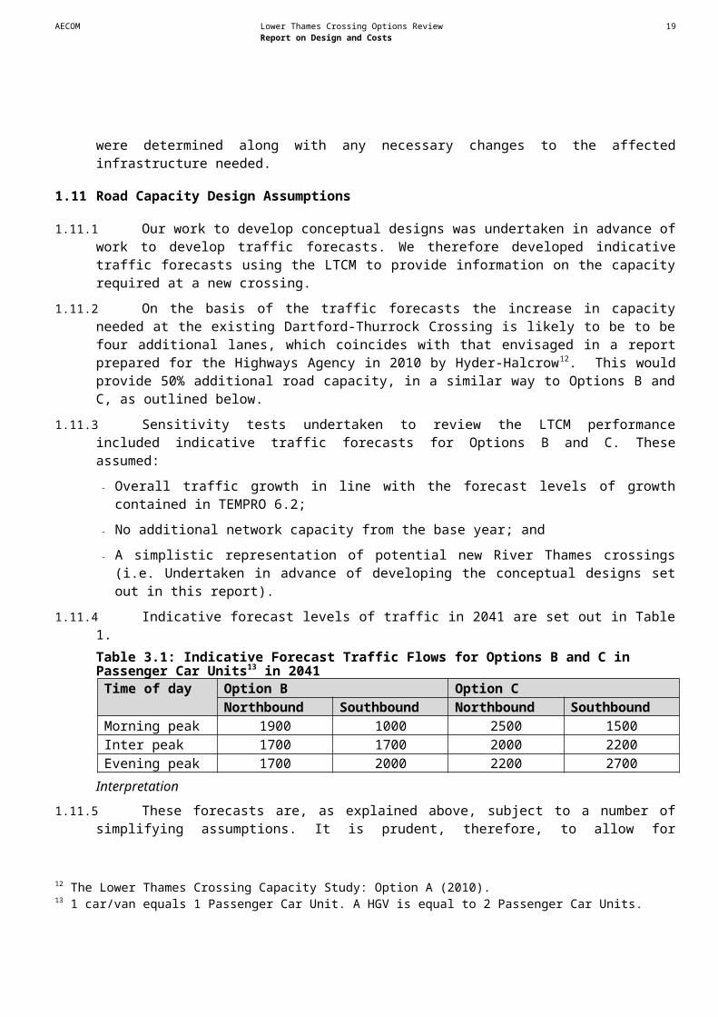
1.11.4 Indicative forecast levels of traffic in 2041 are set out in Table 1.
12 The Lower Thames Crossing Capacity Study: Option A (2010).
AECOM Lower Thames Crossing Options Review 16Report on Design and Costs
Table 3.1: Indicative Forecast Traffic Flows for Options B and C in Passenger Car Units13 in 2041
Time of day Option B Option CNorthbound Southbound Northbound Southbound
Morning peak 1900 1000 2500 1500Inter peak 1700 1700 2000 2200Evening peak 1700 2000 2200 2700
Interpretation
1.11.5 These forecasts are, as explained above, subject to a number of simplifying assumptions. It is prudent, therefore, to allow for uncertainty in considering the potential capacity requirement for a new crossing.
1.11.6 Our judgement, reflecting both the nature of these simplifying assumptions, in addition to general forecasting uncertainties, is that demand is likely to be within +/-25% of the forecasts set out in Table 1. This would indicate that, in 2041, traffic flows at Option C could reach 3400 PCUs / hour in the southbound evening peak and 2500 PCUs / hour at Option B, also, in the southbound evening peak. Both of these figures are within the notional capacity of a two lane dual carriageway road, which can accommodate approximately 1800 PCUs / hour per lane. On this basis, new crossings at Options B and C with two lanes in each direction are expected to provide sufficient capacity.
1.11.7 We recognise there are uncertainties and risks that additional capacity could be required. Additional lane capacity would also provide added resilience. A new crossing structure would represent a high cost element, which could not be adapted to provide additional capacity at a later stage without incurring disproportionately high costs. We have, therefore, also considered the cost of constructing crossing structures providing three lanes in each direction overall at each of location options A, B and C. The incremental benefits of a new crossing providing three rather than two additional lanes in each direction overall will be considered further during the detailed design process once a decision about the location of a new crossing has been made.
1.12 Design Assumptions for Roads and their Compliance with Standards
1.12.1 This section provides more detail on the design assumptions and issues that were taken into account for roads, the main River Thames crossing structures and other structures identified in the conceptual design process for each Option.
Road Standards
1.12.2 Whether new road links are designed to motorway or all-purpose standards significantly affects performance and capital and operating costs.
1.12.3 Road standards are defined in the DMRB. They differ for motorways and all-purpose roads in the following ways:
- Junction and access strategy;
- The appropriate route alignments; and
- Road widths.
1.12.4 Motorway road standards provide a high level of service with access only available at interchanges with trunk roads and other main routes. Design standards for motorways limit gradients to a
13 1 car/van equals 1 Passenger Car Unit. A HGV is equal to 2 Passenger Car Units.
AECOM Lower Thames Crossing Options Review 17Report on Design and Costs
maximum of 3% whilst 4% is permitted for all-purpose dual carriageway roads. Motorways also include a hard shoulder whilst all purpose dual carriageways are provided with a narrower hard strip. Adopting motorway standards would thus increase the carriageway width (allowing for a hard shoulder) and, due to the gradient requirements, would also increase the length of crossing structures required to traverse the River Thames, in both cases increasing capital costs.
1.12.5 The existing Dartford-Thurrock crossing structures are designed to all purpose rather than motorway standards (i.e. with a hard strip instead of a hard shoulder) and it would be most natural for a new crossing at Option A to be designed to the same standard. A crossing at Option B would connect two A roads and so it would be most natural to provide a new crossing at Option B to all purpose rather than motorway standards too. A crossing at Option C would connect the M2 with the M25. There might therefore be a case to provide a new crossing at Option C to motorway standards. If a decision is taken to provide a new crossing at Option C then the potential benefits for longer distance traffic would need to be judged against the reduced access for local traffic to determine this point. However, at this stage we have assumed that the routes for all options should be designed as all purpose roads. In all cases and for all options, all link roads connecting crossing structures with the existing road network have been designed as dual carriageways.
1.12.6 The structures forming the existing Dartford-Thurrock Crossing have maximum road gradients of 3.5%, with the exception of the southern approach to the QEII Bridge where the maximum gradient is 4%, due to the constraints of the Toll Plaza. We have similarly assumed a maximum gradient of 3.5% for all new crossing structures for consistency with the existing design, unless constraints force steeper gradients to be applied. Route Design
1.12.7 The assumed illustrative routes for new crossings are consistent with routes set out in the 2009 Study and have only been altered where necessary.
1.12.8 Design speeds have been set at 120kph (which, in terms of the DMRB is equivalent to the 70mph National Speed Limit), wherever practicable but with restrictions at the new crossings and other areas, as further described in Chapters 5, 6 and 7. All design work on notional alignments has been undertaken in accordance with the DMRB standard TD9/93 using MX road design software.
1.12.9 The design of assumed illustrative horizontal alignments and some critical junction areas has been developed with Ordnance Survey and aerial mapping supplied by the DfT.
1.12.10The design of assumed illustrative vertical alignments has been developed to provide the necessary clearances to:
- Allow for compliance with PLA navigation requirements;
- Provide the necessary grade separation at grade separated junctions and interchanges;
- Provide for continuity of roads, rail lines and accesses crossing assumed illustrative routes, either over or under; and
- Pass over or under critical utilities services, where possible.Junction Connections
1.12.11Main connections with the existing road network have been assumed to be provided by free-flow junctions where practicable but where necessary due to physical constraints grade separated junctions with roundabouts have been assumed. In some cases, limited design of assumed illustrative alignments has been undertaken to prove buildability. Otherwise, layouts have been developed on the basis of simple geometry using the applicable DMRB standards.
AECOM Lower Thames Crossing Options Review 18Report on Design and Costs
1.13 Conceptual Design Assumptions for Bridge Structures
1.13.1 Illustrative conceptual solutions for a bridge structure, have been developed for each of the assumed illustrative routes for new crossings at location options A, B and C. Structure Type
1.13.2 The combination of site conditions and vertical and horizontal navigational constraints would require a main span in excess of 450m at all of the locations considered. The most appropriate structural type for this magnitude of span is a cable supported bridge, either suspension or cable stayed. It is generally accepted that where spans are less than 800m, cable stayed bridges offer a more economical solution than suspension bridges due to their ease of construction and speed of erection. Thus for all options, the bridge solution assumed comprises a cable stayed bridge, with the span determined to best suit the actual site conditions. The proportion of main span and back spans is arranged to simplify erection and reduce live load deformation. Cable Stayed Bridge Layout Design
1.13.3 Among the cable configurations used in modern cable stayed bridges, semi-harp stay is the most popular due to its appearance. It also enables overall cable length to be optimised and, potentially allow, deck erection to commence before the pylon is constructed to its full height. This configuration, with a two-plane cable system having overall torsional efficiency, was assumed for all options. This arrangement is also similar to that used on the existing QEII Bridge. The Pylons
1.13.4 As the principal supporting structure for the cables, the selection of material and shape of pylon is influenced by the overall economy and aesthetics. In the current scope, detailed work has not been carried out to determine the most suitable form of the pylon. A steel pylon was used for the existing QEII Bridge for speed of erection. However, recent studies have shown that concrete pylons are competitive for heights up to approximately 250m, despite their considerable weight, subject to local conditions. They perform better than steel pylons during construction under aerodynamic excitation and have lower in service lifecycle costs. For these reasons, a concrete pylon is assumed, but with the shape similar to the existing QEII bridge to give better overall aesthetics. These matters are subjective, and would need to be considered in more detail in later studies.The Main Span Bridge Deck
1.13.5 The development of a cross-section for the stiffening deck girder needs to take into account its participation in the total structural system for resisting vertical and lateral loads as well as aerodynamic behaviour and ease of erection. In the absence of more detailed work, the deck arrangement of the existing QEII Bridge has been assumed. It has been shown that this deck arrangement performs reasonably well for the required deck width except possibly with wind shielding attached. It is considered that modifications to this basic cross-section would enable the bridge deck to satisfy the aerodynamic stability with wind shielding added, which would need to be proved by wind tunnel testing. Section models as well as full aero-elastic models would need to be prepared and stability proved both during construction and service. These additional activities are reflected in the cost estimate for all of the options.
1.13.6 Thus, the deck arrangement assumed for all options comprises four steel plate girders acting compositely with a concrete slab having transverse diaphragms at cable locations. This deck arrangement lends itself to be fabricated in segments, lifted up from a river barge or ground and bolted or welded together for progressive cable erection. This form of deck arrangement is also known to provide economical solutions for the bridge substructure and foundation.
AECOM Lower Thames Crossing Options Review 19Report on Design and Costs
1.13.7 The assumed deck form for the approach viaducts is similar with steel composite girders with spans ranging from 50 to 80m. The actual span lengths would be determined by ground conditions and overall economics depending on substructure and superstructure costs. The deck would need to be made continuous for economy and to improve ride quality. Depending on the final deck profile, the approach spans may be constructed by launching.
1.13.8 The conceptual solutions accord with DMRB standards. The assumed deck width would accommodate four 3.65m wide lanes and 1m wide hard strips, cable stay anchorages and deck furniture. For Option A traffic is assumed to use the bridge in only one direction. For Options B and C, however, additional deck width has been allowed for the central reserve to allow for two way traffic. More details on deck widths are given in Chapters 5, 6 and 7.
1.13.9 Vehicle Restraint Systems would be required along the edges of deck to have containment, impact severity level and working width appropriate for the road classification and design speed. The deck cross-sections developed would permit the restraint systems to satisfy the DMRB requirements, in particular TD19/06 – Requirements for road restraint systems and EN 1317-1.
1.13.10In the selection of material for the bridge construction, due consideration was given to the requirement in the DMRB for a 120 year design life, taking into account environment and durability issues. The exposure class and protection measures for concrete and steel are assumed to be that applicable for a marine environment, which has been reflected in the cost estimates.
1.13.11Modern cable stayed bridges have enhanced durability requirements and these have been assumed. Anti-vandalism and fire protection measures are assumed for the stays up to a height of 4m from deck level. Bridge Foundations
1.13.12The main pylons of the bridge were assumed to be supported on cellular voided precast concrete caisson, one for each pylon, formed by sinking them on a prepared rock blanket laid over a suitable founding stratum. The back span pier foundations were assumed to be formed within steel sheet pile coffer-dams and plugged with tremie concrete. The substructure for the back span and approach viaduct would consist of hollow concrete sections with pier heads to support the bearings. The foundations for the approach spans are assumed to be piled foundations for the purpose of the cost estimate.Navigational Clearance
1.13.13The navigation (air draught) clearance required by the PLA for shipping is provided within the main bridge span. Air draught requirements increase downstream to accommodate larger ships operating towards the ports of Tilbury and London Gateway. The ship impact requirements for the two main piers, which support the pylons situated in deep water within the river, might also need to increase downstream; this point would need to be determined at later design stages. Allowance has been made for the back span piers to be designed for ship impact, but from smaller ships, in accordance with the DMRB.
1.14 Conceptual Design Assumptions for Tunnel Structures
1.14.1 Both a bored tunnel option and an immersed tunnel option have been considered. Bored Tunnel
1.14.2 A bored tunnel requires the construction of a circular tunnel at depth, without removing the ground above, using a Tunnel Boring Machine (TBM). TBMs and their associated back-up systems are used to automate the excavation and lining of the tunnel. A number of approaches to lining tunnels are available. The choice between these approaches is influenced partly by ground conditions and
AECOM Lower Thames Crossing Options Review 20Report on Design and Costs
construction preferences; however, the most common approach is to use a precast concrete segmental lining and therefore we have assumed this approach.
1.14.3 A variety of TBM types exist to allow tunnelling to proceed in very different ground conditions from hard rock to soft water-bearing ground. New advances include slurry TBMs and earth-pressure balance machine (EPBM) TBMs that have pressurised compartments at the front end to allow them to be used in difficult conditions below the water table.
1.14.4 The existing tunnels at the Dartford-Thurrock Crossing were both delayed by the difficult ground conditions encountered and the resulting high rates of water-ingress. Similar conditions are expected to be met at all three crossing locations under consideration and thus the choice of TBM is likely to be between a Slurry and EPBM TBM. The HS1 rail tunnel beneath the River Thames, which crosses adjacent to Option B, was constructed using a slurry TBM and we have assumed a similar method would be selected.Immersed Tunnel
1.14.5 The alternative immersed tunnel construction is a shallow depth tunnel with the top of the finished tunnel structure lying just below the riverbed. If the conditions allow, immersed tunnels offer many advantages over bored tunnels:
- They can be constructed with a cross-section suited to the project spatial requirements;
- They can be constructed swiftly (provided element production is sufficiently fast);
- Their shallow depth permits tunnel entrance portals to be constructed closer to the banks, thereby reducing the overall length and hence, construction, operational and maintenance costs.
1.14.6 A most important consideration, however, would be disruption to river traffic during construction due to the active work on the riverbed.
1.14.7 The construction industry is well versed in the techniques needed to construct an immersed tunnel, with many projects having been successfully completed in the UK and around the world. In the UK, recent immersed tunnels have been used on the A55 Conwy Bypass in North Wales, the River Medway, and the River Tyne.
1.14.8 The method assumed for constructing an immersed tunnel applies the following several relatively straightforward techniques.
1. Dredge a trench in the river bed.
2. Cast concrete tunnel elements in a fabrication yard / dry dock and prepare for floating them to tunnel location.
3. Float elements, tow to crossing location and lower element on temporary foundation supports.
4. Connect element with its neighbouring, previously lowered, element.
5. Carry out measures to stabilise the element.
6. Backfill trench and cover structure to prevent future damage.Operational and Safety Considerations
1.14.9 Whether bored or immersed, tunnels require numerous safety facilities. The design for safety requires a holistic approach combined with value engineering to arrive at the lowest whole life costs. Due allowance has been made in the cost estimates for these facilities with emergency stations assumed at 50m spacing and cross connections assumed at 100m spacing in accordance with DMRB standards (BD78).
AECOM Lower Thames Crossing Options Review 21Report on Design and Costs
1.14.10Cross-connections between the tunnels allow users to evacuate into the unaffected tunnel. The ground between bores at the location of the cross-connections is treated in advance of the tunnelling operation to control ground movements and water inflows. The construction of these cross-connections would require many difficulties to be overcome14.Other Technical Considerations
1.14.11From a structural design perspective the following considerations, while not necessarily exhaustive, would need to be examined in more detail before settling on a bored or an immersed tunnel option. Other Technical considerations - Bored Tunnel
1.14.12The existing ground conditions would influence decisions on constructability and the alignment of a new tunnel. The following considerations are of particular importance:
- The anticipated inflows associated with the fissures in the rock and the likely high water pressures would influence the selection of TBM used and the construction risk associated with a bored tunnel option.
- The ground through which the tunnel traverses would be a major factor in determining minimum depth of the tunnel below river bed level. This depth, along with the approach gradients, would influence the overall length of the tunnel.
- Tunnelling will induce ground movements. Ground movement or settlement can adversely impact other structures along, and to the sides of, the alignment. The magnitude of the settlements is dependent on ground conditions and the construction processes and control measures adopted.
- The ground conditions and the anticipated inflows would establish the ground treatment measures needed at the cross connections and the associated construction risk.
1.14.13A suitable site for the disposal of spoil would be needed. If spoil material is shown to be contaminated the disposal site options would be restricted.
1.14.14Separation of tunnel bores is relevant in design as when a tunnel is excavated the ground loads ‘flow’ around the opening. With two bores the ground between can be the most heavily loaded, thus the ground conditions and its ability to support these loads, particularly during construction, influence the minimum separation of the bores. This minimum separation could affect the horizontal alignment and the land take on the road approaches.Other Technical considerations - Immersed Tunnel
1.14.15Particular considerations that would influence detailed design considerations are set out below.
- A detailed survey of the river bed including the composition of the ground to below the formation level of an immersed tunnel would determine the ability to dredge the river bed to formation level.
- On shore excavation for the approach structures can be dual purpose and be used for fabrication of the elements. In such circumstances the construction of a cofferdam is required to shut off the excavation from the river. If construction of the elements on site is not practicable then a suitable dry dock would need to be sought. While preferable it is not essential that this is situated close to the tunnel site.
14 An alternative to cross-connections would be to provide a protected passageway to the side of the carriageway. This approach would require a larger tunnel to accommodate the extra space required and would almost certainly require the vertical alignment to be lowered, increasing the overall tunnel length.

AECOM Lower Thames Crossing Options Review 22Report on Design and Costs
- The size of the fabrication site is a major factor in determining the size of the immersed tunnel elements and its cost effectiveness.
- Strong water movements can hamper both the transportation and the immersion of the elements.
- Many of the construction operations would impact river traffic. These include dredging, foundation construction, transportation of the elements, immersing the elements and backfilling.
- Construction of existing immersed tunnels has shown that disruption can be limited by adopting appropriate working methods. It is likely that the navigation channel could be maintained with only limited disruption during dredging, foundation construction and backfilling works. Transport and particularly the immersion of tunnel elements would be likely to warrant a temporary closure of the river to shipping of a day or so for each of the elements.
- Dredging and maintenance of the trench for element installation would affect the environment at the site. However, dredging firms have developed solutions to mitigate the ecological and environmental effects of the process. Results from existing immersed tunnel schemes have suggested that the effects of dredging are often temporary.
1.15 Other Design Issues
Free-Flow Charging technology
1.15.1 The charge collection method at the existing Dartford-Thurrock Crossing is planned to change to a free-flow system in 2014. The toll plazas will be removed after this and through road lanes provided. The speed limit of 50mph on the crossing itself would be extended through to the A282 connection to the South.
1.15.2 Charge collection is expected to be by Automatic Number Plate Recognition Tags fitted within vehicles and other suitable methods. Detection equipment and overhead cameras used for these charge collection methods would be installed at suitable locations on the south side of the crossing. Arrangements for the escorting of dangerous loads would continue through the tunnels. To facilitate this the stacking area beyond the northbound toll plaza may be expected to need alteration to suit the entry of escorted convoys onto the free-flow road arrangement into the west tunnel.
1.15.3 Assumptions about Free-Flow tolling technology at Options A, B and C are described in Chapters 5, 6 and 7.Passage of Dangerous Loads
1.15.4 Facilities for queuing and the escorting of dangerous loads would be required for the tunnel crossing structure alternatives at each of the Options under consideration.

AECOM Lower Thames Crossing Options Review 23Report on Design and Costs
1.16 Introduction
1.16.1 This chapter sets out the methodology we have applied to estimate capital costs using conceptual designs.
1.16.2 As explained in Chapter 3, conceptual designs are based on the assumption that new crossings would provide an additional two lanes in each direction overall15, constructed to all purpose rather
than motorway standards.
1.16.3 There is insufficient information at this stage of the work to determine the type of structure (tunnel or bridge) for a new crossing or the capacity required for the crossing structure. We have therefore also set out alternative cost estimates based on crossing structures providing an additional three lanes in each direction overall at each location16.
1.16.4 The method for estimating maintenance and operating costs of each route option is the subject of a separate technical note.
1.17 Overall Approach
1.17.1 Three point minimum, most likely and maximum capital cost estimates were prepared in line with HA best practice. Estimates were developed in four stages, as elaborated further in the following sections of this chapter:
- Construction Costs: initial minimum, most likely and maximum estimates of construction costs were produced using conceptual designs;
- Options and Development Phase Costs: minimum, most likely and maximum cost estimates were then established for the options and development phases (see Figure 4.0 and Table 4.0 below);
- The Cost of Risk: thirdly, construction risks were identified. The cost of these risks was estimated and added to minimum, most likely and maximum estimates;
- Inflation, Programme Risk and Range Narrowing: further allowances were then added for programme risk and assumed future inflation prior to range narrowing between minimum and maximum estimates to produce final minimum, most likely and maximum estimates.
1.17.2 Outturn costs have been produced using the Highways Agency’s Cost Estimation Summary Spreadsheet (CESS) and Range Estimation Tool (RET). The CESS provides a breakdown of costs incurred throughout scheme life from the options phase through to completion of construction and handover, in line with the HA’s Project Control Framework, as shown in Error:Reference source not found. The RET is used to add allowances for inflation and programme risk and to narrow the range between the minimum and maximum estimates.
15 At location Option A this would be achieved by providing a new four lane structure(s) for northbound traffic and switching the direction of traffic travelling through the existing east bore tunnel to provide two extra lanes for southbound traffic (see Chapter 5 for further details). 16 Again, at Option A this would be achieved by providing a new six lane structure for northbound traffic and altering the use of existing structures.
3 Approach to Estimating Capital Costs

AECOM Lower Thames Crossing Options Review 24Report on Design and Costs
Figure 4.0: HA Project Control Framework Phases and Stages
1.17.3 We have presented costs to show the split between those costs attributable to the main crossing structure and all other costs involved with linking crossing structures to the existing road network. The HA provided assumptions to attribute the distinct cost elements (defined below) between the main crossing and other road network connections.
1.18 Composition of Capital Costs
1.18.1 Our estimates of capital costs comprised consideration of the cost elements shown in Table 2. Table 4.0: Capital Cost Definitions and Assumptions
Cost Item DescriptionTime
incurred
Source
Options Phase
This includes the cost of identification of various scheme options and selection of a preferred option. Designs considered within the options phase would be produced at a more detailed level than those used to inform this study. A preferred option would be selected following public consultation process.
2013 - 2016
Costs established from AECOM database of comparable projects. Costs reviewed and revised in discussion with Highways Agency.
Development phase, preliminary design
Preliminary design and statutory procedures to authorise a chosen scheme, including statutory processes.
2016 - 2019
Cost rates established from AECOM database of comparable projects
Development phase, land
Land costs including land purchase, blight and compensation
2020 - 2021
Cost rates established from AECOM database of comparable projects.
Construction phase, roadworks
The costs of approach roads and connections to the existing road network, junctions and side road alterations
2021 – 2024
Cost rates established from AECOM database of comparable projects, reviewed by Highways Agency.

AECOM Lower Thames Crossing Options Review 25Report on Design and Costs
Cost Item DescriptionTime
incurred
Source
2021 - 2024
Construction phase, main crossing structure
The direct costs associated with providing the new crossing structure
Cost rates established from reported costs for Second Forth Crossing, and AECOM database of comparable projects.
Construction phase, other structures
The costs of constructing all other structures including those needed for bridging existing rail lines and roads
Cost rates established from AECOM database of comparable projects, reviewed by Highways Agency.Construction
phase, contractor’s fee
Costs other than the direct costs and overheads
Construction phase, Statutory Undertakers
Costs for relocating utilities services including gas, electricity, telecommunications and water pipelines
Cost rates established from AECOM database of comparable projects.
Construction phase, construction overheads
Other costs Cost rates established from AECOM database of comparable projects, reviewed by Highways Agency.
Projectoverheads andmanagement
Costs incurred during construction by the main Contractor providing management, office/welfare and general equipment
2012-2025
Non Recoverable VAT
Incurred by a highway authority for construction work outside the existing highway boundary
2012-2025
Applicable cost based on assessment of land requirement
Inflation Changes in cost, reflecting the expected time the expenditure is incurred
2012-2025
DfT advice on construction cost inflation (see Table 3)
Programme Risk
Changes to standards, network operation and other imposed change like legislation, that affect all projects over time.
n/a Highways Agency Advice
1.19 Methodology used to Estimate Construction Costs
1.19.1 Construction cost estimates have been developed using historic data from AECOM’s own database, (using the most recent available project sources from the UK and overseas), and information supplied by the HA. These sources were interpreted to provide cost rates, (i.e. cost per km). Which were then applied to the dimensions of the conceptual designs to provide an initial estimate of minimum, most likely and maximum costs.
1.19.2 Rates for all cost estimates are based on 2012 prices (Quarter 1).

AECOM Lower Thames Crossing Options Review 26Report on Design and Costs
1.19.3 We have identified costs for roadworks using basic quantities derived from given link lengths, road standards and widths. Due allowance has been made for earthworks and for where there are special issues, for example where embankments would be constructed on soft ground. Conceptual junction designs have been measured on a length basis with assumed road and roundabout widths.
1.19.4 Cost estimates for the main River Thames crossing structures have been based on the dimensions set out in the layout drawings shown in Appendix 1. Cost rates for cable stayed bridge crossing structures have been based on reported costs for the similar Forth Replacement Crossing Bridge in Scotland, currently under construction. Bored tunnel costs for roads vary worldwide - typical costs have been presented in British Tunnelling Society (BTS) paper “Infrastructure UK Cost Study – Tunnels” October 2010. The rates used for estimating the cost of bored tunnels have been derived from AECOM’s database whilst benchmarking against the BTS data. Cost estimates for immersed tunnel structures have been developed using the designs shown in Appendix 1 and then benchmarked against typical worldwide costs to ensure they are robust. In all cases AECOM have sought to use typical rates from projects of a similar size and nature.
1.19.5 Costs of other structures, (i.e. other bridges and retaining walls), have been derived from measures of approximate bridge deck area or wall height, as appropriate, and using typical cost rates that have been accredited on the High Speed 2 (HS2) rail project. Many of the rates used for construction use the same source as used for the SPONs Price Books published by AECOM’s company Davis Langdon.
1.19.6 Beyond basic construction costs, an approximate estimate for the costs of protecting and diverting utilities services has been provided on the basis of typical costs for schemes of a similar size, and more specifically, on the basis of the effects on known major plant such as high pressure gas pipelines and overhead electricity lines.
1.19.7 Allowance was made for additional free-flow technology monitoring and collection facilities at Option A. Cost estimates for Options B and C assumed new separate free-flow monitoring and collection facilities.
1.19.8 VAT is applied to construction costs applying to areas outside areas already owned by the Highway Authority. For each of the options, we have made an assessment of these areas and so calculated the amount of VAT applying at current rates.
1.20 Methodology used to Estimate Options and Development Phase Costs
1.20.1 Cost elements covering the Options and Development Phases (see Figure 4.0 and Table 4.0 above)have been based on costs from the AECOM cost database, appropriate to the scale of the assumed illustrative route for new crossings at Options A, B and C, and have been reviewed and refined following HA advice.
1.20.2 Typical costs incurred in the options stage (Options Identification and Options Selection) include initial route studies, public consultation and reporting.
1.20.3 During the Development stage, a preferred scheme is prepared for assessment and is subject to statutory procedures prior to eventual authorisation. Costs for this process and a Public Inquiry have been included in estimates. Land purchase and compensation costs have been based on an assessment of the land use and by applying typical rates used for the HS2 project.
AECOM Lower Thames Crossing Options Review 27Report on Design and Costs
1.21 Approach to Quantifying the Cost of Risk
1.21.1 A risk assessment was carried out to identify potential risks, the likelihood that they would occur and their potential cost impact. These risks were then grouped according to the cost element categories in the CESS. The minimum, most likely and maximum cost of risk was calculated for each cost item using the HA’s calculation methods and was added to the estimated minimum, most likely and maximum costs for the Options, Development and Construction phases.
1.22 Inflation, Programme Risk and Range Narrowing
1.22.1 Predicted price inflation was incorporated into cost estimates by the HA using the RET following a profile supplied by the Department for Transport: Table 4.1: Inflation with respect to calendar year
Financial Year 2012 2013 2014 2015 2016 2017 2018 2019 2020-2025...Construction inflation 4.5% 4.5% 4.4% 4.3% 4.2% 4.1% 3.8% 3.8% 3.5%
1.22.2 A separate assessment of risk costs called Programme Risk, which reflects general changes over time in factors such as legislation, environmental mitigation, highway standards and our operating regimes was also made using the RET. The range between minimum and maximum estimates was also narrowed slightly to produce a final set of minimum, most likely and maximum cost estimates for each crossing structure at each of Options A, B and C (and the Option Cvariant)
1.23 Methodology used to Estimate Crossing Structures providing an additional three lanes in each direction
1.23.1 As described above, whilst conceptual designs have been based on crossings providing an additional two lanes in each direction at each location, costs have also been produced for crossing structures providing an additional three lanes in each direction. These estimates do not include wider carriageway widths for any potential link roads away from the main crossing structures.
1.23.2 A structure providing three additional lanes in each direction would necessarily be wider than a structure providing two additional lanes in each direction. A factor was therefore applied to the cost rates associated with the most likely estimates for the main structures17 to allow for these increased widths; i.e. for three additional lanes instead of two additional lanes.
1.23.3 The factor applied to cost rates for a bridge structure at Option A was 1.32, reflecting the proportional increase in width of bridge deck needed to accommodate an extra two lanes whilst meeting the design standards set out in the DMRB. This factor was slightly lower for bridge structures at Options B and C (1.27), reflecting the fact that bridge structures at these locations would have a central reservation. The width of bridge crossings at Options B and C would therefore need to increase by a proportionately smaller amount than at A to accommodate extra lanes.
1.23.4 Relevant cost rates for immersed tunnel structures were multiplied by 1.29; reflecting the increased width of the structure needed to carry an additional lane in each cell.
1.23.5 A higher factor was applied to cost rates for bored tunnel structures in reflection of the larger cross sectional area involved (i.e. bored tunnels have a circular cross section whilst immersed tunnels
17 Main structure costs included costs associated with underbridges, overbridges, gantries, tunnels, viaducts, tunnels, culverts, retaining walls and other minor structures, as appropriate at the crossing.

AECOM Lower Thames Crossing Options Review 28Report on Design and Costs
have a rectangular cross section). A factor of 1.62 was applied, representing the increase in the internal volume of a tunnel needed to carry an extra two lanes of traffic.
AECOM Lower Thames Crossing Options Review 29Report on Design and Costs
1.24 Introduction
1.24.1 This Chapter explains how the methodologies described in Chapters 2-4 used to identify constraints, develop conceptual designs, and produce cost estimates, were applied to produce
conceptual designs and cost estimates for a new crossing at Option A.
1.25 Existing Crossing Layout and Associated Junctions
Dartford–Thurrock Crossing Facilities
1.25.1 The existing Dartford-Thurrock Crossing has the following features:
- Two northbound tunnels, each containing two lanes (restricted clearances apply in the west bore tunnel)
- Southbound bridge carrying four lanes (the QEII bridge)
- Toll plazas for each direction are situated on the southern side of the crossing – (Note: these will be replaced by free-flow charging technology, which is due to be introduced in 2014)
- Ventilation buildings
- Turn around facilities
- Facilities for controlling the passage of dangerous loads
- Tunnel control buildings
1.25.2 The tunnels are classed as Category C under the European Agreement concerning the International Carriage of Dangerous Goods by Road. Vehicles using tunnels that fall under this category stop in a separate queuing lane and await escorted access to the tunnel in convoy formation.South Layout Junction 1a – A206 connection
1.25.3 Close to the south side of the toll plazas is situated Junction 1a, which comprises a dumbbell type grade separated junction connecting to the A206 routeing to Dartford in the West and Gravesend in East. Lanes to and from the toll plazas connect directly to Junction 1a. The A282 approach is a four lane dual carriageway with hard shoulders.
1.25.4 The toll plazas will be removed after free-flow charging technology is introduced and the Junction 1a connections will merge in with the A282 carriageways.North Layout
1.25.5 The southbound M25 becomes the all-purpose A282 to allow non-motorway vehicles to access the crossing. Junctions 30 and 31 on the M25 are close to the Dartford-Thurrock Crossing and are interconnected. North Layout - Junction 30
1.25.6 Junction 30 provides access between the M25 and the A13 Trunk Road. It is a signal controlled gyratory type of junction and subject to heavy traffic flows from commuter traffic combined with shoppers for the nearby Lakeside Shopping Centre.
4 Option A
AECOM Lower Thames Crossing Options Review 30Report on Design and Costs
1.25.7 On the north side, there is a lane drop in the southbound direction from four to three lanes and a corresponding lane gain from three to four lanes in the northbound direction.
1.25.8 On the south side, northbound direction, there is a lane drop from four lanes to three lanes but on the heavily trafficked southbound merge, no lane gain to the existing three lane carriageway.North Layout - Junction 31
1.25.9 Junction 31 is the connection to the A1306 and also the point at which the M25 becomes the A282, allowing non-motorway traffic to join and leave in the southbound and northbound directions respectively. The signalised roundabout below the motorway carriageway provides connections to Purfleet and the Lakeside Trading Estate. In the northbound direction there is a taper exit, whilst southbound there is a lane gain to 4 lanes width.
1.26 Assumed Illustrative Route
1.26.1 The additional road capacity associated with a new crossing at Option A is, as explained in Chapters 3 and 4, assumed to be for four extra lanes (providing an additional two lanes in each direction overall), representing a 50% increase on the existing four lanes in each direction. For the purposes of this exercise it has been assumed that this additional capacity would be provided through a new structure (or structures) upstream of the existing bored tunnels. Northbound traffic would use the four lanes provided by the new structure(s) and the existing west bore tunnel. Southbound traffic would use the QEII Bridge and the existing east bore tunnel.
1.26.2 We briefly considered the merits of other arrangements. However, we considered that a downstream bridge would be too close, aerodynamically, to the existing QEII Bridge. As there are more constraints downstream of the existing structures the tunnel options were also assumed to be on the upstream side. A similar road layout was assumed for tunnel and bridge crossing options, as described below.
1.27 Review of Environmental Constraints
Air quality (see Figure 1)
1.27.1 AQMAs have been declared for the A282 Junction 1a-Junction 1b by Dartford Borough Council and at locations adjacent to the A282 by Thurrock Council (see Figure 1). If these AQMAs were still in existence in the opening year of a new crossing at Option A, this could represent a significant environmental constraint.
1.27.2 The assumed illustrative route for a new crossing at Option A passes through commercial and residential areas. An initial assessment shows that to avoid adverse effects from air pollution, a new road would need to be located at least 120m from the road centre to the nearest properties.
1.27.3 Option A is located further than 200m from any designated nature conservation sites (i.e. SACs, SPAs, SSSIs or Ramsar sites) indicating that designated features sensitive to air pollution are unlikely to be adversely affected.Biodiversity (see Figures 2 and 3)
1.27.4 The following biodiversity constraints have been identified for Option A (see Figures 2 and 3):
- Thames Estuary Marine Conservation Zone as recommended to Government
- West Thurrock Lagoon and Marshes SSSI, located 0.2km to the east of the existing Dartford - Thurrock crossing
- Mudflat habitat on the northern and southern banks of the River Thames

AECOM Lower Thames Crossing Options Review 31Report on Design and Costs
- Reed bed habitat to the west of the A282 and south of the power station
- Ancient Woodland at Watts Wood although this is unlikely to be affected and will not be considered further
1.27.5 Mudflat habitat cannot be replaced and is considered to be a major constraint.Heritage of historic resources (see Figure 4 and Appendix 3)
1.27.6 No Scheduled Monuments, Registered Parks and Gardens, Conservation Areas or listed buildings would be affected by a new crossing at Option A.
1.27.7 There are several known archaeological sites within 500m of the assumed illustrative route of a new crossing at Option A (see Figure 4). None of these represent a significant constraint. However, the following sites within 50m of the assumed illustrative route are of particular note (see Appendix 3 for further details):
- Second World War spigot mortar site, now destroyed, north of London Road, West Thurrock (Site 81)
- Ring ditch visible on aerial photographs (Site 271) Landscape / Townscape (see Figure 5)
1.27.8 No landscape designations (e.g. AONBs) would be affected. As described above, there are no built heritage features, which would have setting issues.
1.27.9 Visual receptors include residential receptors in north-east Dartford, Purfleet and West Thurrock. Other receptors include recreational users of public rights of way and the River Thames. There could be visual impacts, relating to changes in the character of views and visual amenity of visual receptors, as a result of the introduction of traffic and/or highway related structures in views. Visual impacts may be addressed at a future design stage.Noise (see Figure 6)
1.27.10Sensitive receptors for noise include residential properties in Dartford. If road traffic flows were to increase on the A282 and M25, noise levels would also be likely to subsequently increase. Road traffic flows would have to increase by 25% for a corresponding increase in noise level of 1 dB(A). Such an increase in noise is generally regarded as not perceptible and therefore, by itself, is unlikely to be a significant constraint.
1.27.11The residential area in Dartford beside a section of the A282 from London Road to the Dartford Crossing has been identified by Defra’s first round of noise action planning to be a first priority location (see Figure 6). First priority locations are being considered by relevant highway authorities to review what, if any, mitigation actions might be taken. Increasing the noise burden even by a small increment in an area already identified as having potentially unacceptably high noise levels would need to be considered further in subsequent stages, if Option A was taken forward,
1.27.12No impact on tranquillity is likely as Dartford is typically urban and less tranquil compared with more remote areas of Kent and Essex.
Water Environment (see Figure 7)
1.27.13The following water-related constraints have been identified for Option A (see Figure 7):
- River Thames.
- Minor watercourses including a network of small drains, ditches and ponds north and south of the River Thames.

AECOM Lower Thames Crossing Options Review 32Report on Design and Costs
- Locations within Flood Zones 2 and 318 and associated flood defences along the northern and southern banks of the River Thames.
1.27.14The potential exists for changes to take place in the form of the River Thames channel (known as river morphology) in response to a new crossing. These changes would be permanent if a bridge was provided (however, the duration and magnitude of the effect would largely depend on the bridge design). Impacts would also be potentially permanent if an immersed tunnel was provided.
1.27.15Flood risk is also a constraint. Option A is located within the Environment Agency’s Flood Zone 319 and there are flood defences on the north and south banks of the River Thames at this location. If Option A was taken forward, more detailed assessment of flood risk would be required in consultation with the Environment Agency, Land Drainage Authorities and Local Authorities. Summary
1.27.16A number of environmental constraints have been identified that would need to be assessed further if a decision was taken to provide a new crossing at Option A; in particular the impact of a new crossing on mudflat habitat.
1.28 Review of Planning Constraints (see Figure 8a and Appendix 4)
1.28.1 Details of significant planned developments, which could act as potential constraints to the provision of a new crossing at Option A are shown in Figure 8a. The delivery status of each site is summarised in Appendix 4.
1.28.2 The northern extent of the assumed illustrative route for a crossing at Option A would enter Green Belt land to the north of the A1306 in Thurrock20. Green Belt land within Dartford would not be affected. Sites identified by Dartford Borough Council in a Major Sites Briefing Note dated January 2012The Bridge (DA10)
1.28.3 This development was approved in 2003 and comprises a mixture of land uses including approximately 185,500m2 of employment floor space, 1,500 residential units and a primary school. Build-out of the development has already commenced. One of the main vehicle accesses to the site is via the western dumbbell roundabout at M25/A282 Junction 1a. A new hotel is also due to open on the site adjacent to Junction 1a in 2012. The site is served by the Fastrack rapid bus system, with a dedicated busway bridge over the M25 having opened in 2007 connecting The Bridge/Littlebrook with Crossways Boulevard.
Land adjacent to Littlebrook Power Station (DA19)
1.28.4 This site is bounded by the River Thames, to the North, and The Bridge development to the South. Developable land covers only part of the existing Littlebrook Power Station site. The site is set away from the assumed illustrative route for a new crossing at Option A. However, access is gained via The Bridge development at M25/A282 Junction 1a, which could be affected by a new crossing. Planning permission was granted in October 2005 for 25,445square metres of employment floorspace; build-out and occupation has already commenced.
18 Note that the area at risk may be greater than the current Flood Zone 2/3 extent when climate change projections are taken into account.19 1 in 100 or greater annual probability of river flooding or a 1 in 200 or greater annual probability of flooding from the sea20 The A1306 and M25 are both included within Green Belt land within Thurrock.
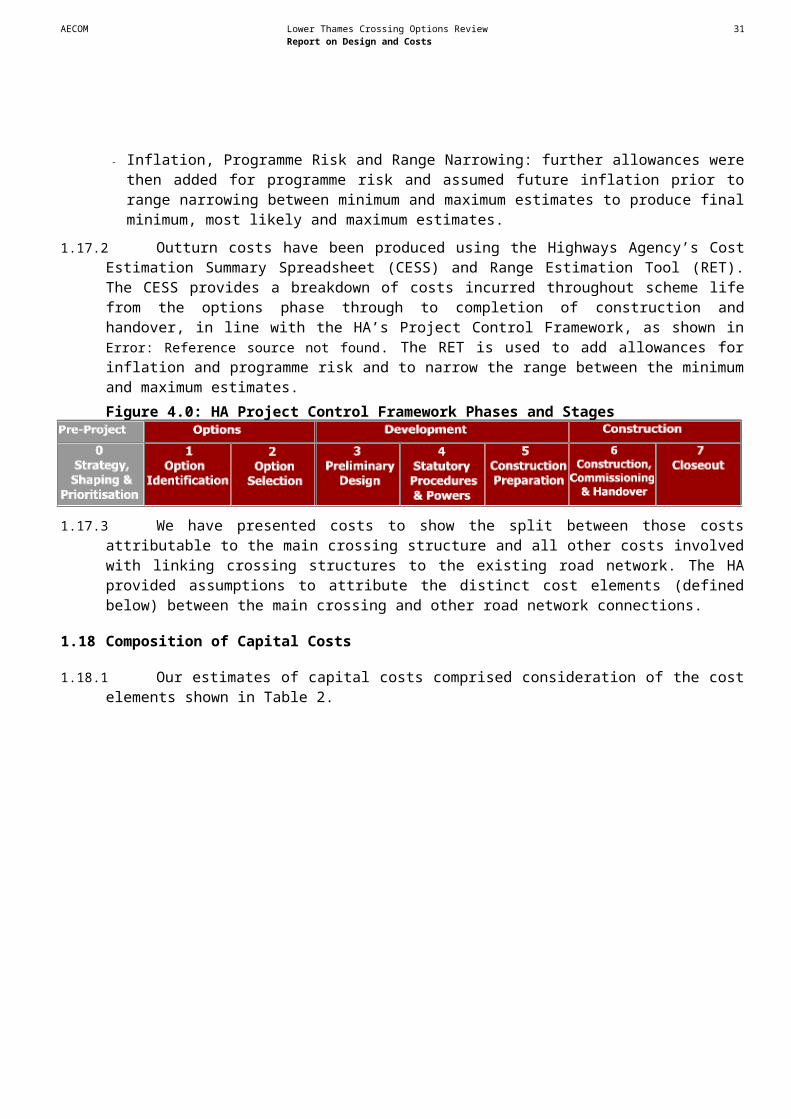
AECOM Lower Thames Crossing Options Review 33Report on Design and Costs
Sites identified in Thurrock Council’s Site Specific Allocations and Policies Issues and Options Development Plan Document Land adjoining Van den Bergh & Jurg, West Thurrock (TH07)
1.28.5 This site is identified as being preferred for industrial and commercial employment. It is located broadly where the assumed illustrative route for a new crossing at Option A ties in with the existing M25 at Junction 31. An adjoining, much smaller site, known as 885-901 London Road, is identified as a potential reasonable alternative site for similar land uses and lies immediately in the path of the assumed illustrative route for a new crossing at Option A, immediately west of the existing Dartford-Thurrock Crossing. Lafarge Getty Site, West Thurrock (TH06)
1.28.6 This site is identified as being preferred for industrial and commercial employment and is located broadly where the assumed illustrative route for a new crossing at Option A could connect in with the existing M25 alignment at Junction 31. Bluelands (west), Purfleet (TH08)
1.28.7 This site is identified as being preferred for industrial and commercial employment. The site is also identified as a possible site for HGV parking. The site is located away from the assumed illustrative route for a new crossing at Option A but could constrain the potential consideration of alternative routes during detailed design if Option A was selected. Summary
1.28.8 A number of planning constraints have been identified that would need to be assessed further if a decision was taken to provide a new crossing at Option A.
1.29 Review of Engineering Design Constraints
Navigation
1.29.1 The PLA has advised that the upper surface of an immersed tunnel at Option A would need to be below the existing river bed. A bridge structure would need to have an air draught of 54.1m above Mean High Water Springs (the same at the QEII bridge); and would need to have a central span of sufficient width for the navigation channel and access to the adjacent jetties. Rail
1.29.2 Two rail lines, HS1 and the London to Southend line pass along the northern bank of the Thames. The HS1 rail line is elevated where it crosses the existing Dartford-Thurrock Crossing, passing over the tunnel approach roads but under the QEII Bridge. Roads
1.29.3 Option A follows the A282 (connecting to the M25) and is crossed by main trunk and other principal roads including the A206 in Kent and the A1306 in Essex. There are also many local roads, which would require alterations to prevent severance.Utilities / Services
1.29.4 Significant services near the assumed illustrative route for a new crossing at Option A include the overhead electricity lines on the south bank of the River Thames from Littlebrook power station. There is, in addition, a local network of utility services within the developed area on both sides of the River Thames.

AECOM Lower Thames Crossing Options Review 34Report on Design and Costs
Ground Conditions/Geotechnics (see Figure 8e)
1.29.5 The area covering Option A on both sides of the River Thames is covered by a significant thickness of superficial deposits over chalk. The superficial deposits (a combination of made ground / alluvium) can be up to 1m thick.
1.29.6 Common issues identified with foundations on chalk include but are not limited to:
- Water induced cavities in the rock strata
- Frost susceptibility
- Differential settlement
1.29.7 Option A does not appear to be directly affected by landfill sites (see Figure 8e).Summary
1.29.8 A number of engineering design constraints have been identified that would need to be assessed further if a decision was taken to provide a new crossing at Option A.
1.30 Assumed Road and Crossing Structures
Overall Road Layout
1.30.1 The constraints imposed by the need to tie a new structure into the existing M25 and to meet river navigation requirements were given particular consideration in designing an illustrative route for a new crossing at Option A. Particular consideration would be given to specific environmental impacts during detailed design to develop suitable mitigation or to refine the route.
North Layout (see Figure 15)
1.30.2 A schematic illustration of the north layout assumed for Option A is shown in Figure 5.0 below. Figure 5.0: Option A – Assumed North Layout

AECOM Lower Thames Crossing Options Review 35Report on Design and Costs
1.30.3 In the southbound direction, we have assumed that four lanes would continue south from the M25, changing from the current lane drop. Lanes three and four on the M25 southbound carriageway would be dedicated to using the southbound tunnel (existing east bore). Chevron markings would deter traffic in these lanes from crossing into lanes one and two. Separating lanes one and two from lanes three and four would also prevent a dangerous manoeuvre following the Junction 30 and Junction 31 merges. Traffic merging from Junction 30 and Junction 31 would have to use the QEII Bridge as a result.
1.30.4 Lane gains would be applied at the entry slip roads for Junctions 30 and 31 successively. In the event that a third lane gain was required from, for example, Junction 30, this could mean that the current Junction 30 southbound lane drop arrangement could be retained. However, provision of an additional lane gain at Junction 30 would require widening of the approach viaduct on the connector road from the Junction 30 gyratory.
1.30.5 In the northbound direction, a similar arrangement has been assumed but in the reverse manner. Northbound traffic in the existing west tunnel bore would not be able to exit at Junction 31. Chevron markings would make the necessary separation. Such traffic would, however, be able to exit to Junction 30.
1.30.6 The additional traffic lane provision arising from the new west side structure would require additional land on the west side from the existing industrial development, the extents of which could be minimised by the introduction of retaining walls. In addition, the existing bridges over the London to Southend rail line and the A1090 London Road would need widening.
1.30.7 The lane schematic based on mapping is shown in Figure 15.South Junction layout (see Figure 14)
1.30.8 A schematic illustration of the south layout assumed for Option A is shown in Figure 5.1 below. Figure 5.1: Option A: Assumed South Layout
AECOM Lower Thames Crossing Options Review 36Report on Design and Costs
1.30.9 As explained in section 3.8, the toll plazas at the existing Dartford-Thurrock Crossing are due to be removed after free-flow tolling technology is introduced. Amendments to the road layout that would be necessary for a new crossing at Option A have taken this into account.
1.30.10In the northbound direction, the four approach lanes from the A282 (south) would be split such that lanes 3 and 4 would be segregated from lanes one and two. This would prevent weaving between the Junction 1a entry to the existing west tunnel bore and from lanes three and four to the new four lane structure. Two lane gains would be made at the Junction 1a entry, the emerging traffic from which, would use the new west side structure
1.30.11In the southbound direction, lanes one and two from the QEII Bridge would be signed as an exit to Junction 1a, whilst lanes three & four from the bridge would form lanes one & two of the A282 and align alongside the two lanes from the existing east tunnel bore. As for the North Layout, segregation of lanes from the tunnel from the QEII bridge lanes would prevent weaving over a short distance and the tunnel traffic could only head for the A282 (south) and would not be able to exit at Junction 1a.
1.30.12It is assumed that access for operation and maintenance requirements to the existing and new structures would be provided for. Facilities for escorting dangerous loads would remain to allow for use of the existing tunnels, or a new tunnel option (see below).
1.30.13The lane schematic based on mapping is shown in Figure 14.Bridge - Road Design (see Figures 9, 10 & 11)
1.30.14The horizontal alignment of the bridge crossing has been assumed to be straight over much of its length but with a small articulation to align with the south layout area and the A282.
1.30.15The vertical alignment of the road over the crossing is mainly constrained by navigational clearance and structural depth requirements. The assumed 85kph Design Speed controls the vertical crest curve so as to provide a Sight Stopping Distance of 160 metres, as required by the relevant design standard. This curve extends approximately over the main navigation span. Attaining the necessary height for the navigation crossing would require a long approach gradient, similar to the QEII Bridge. The maximum gradient for a dual carriageway permitted by current design standards is 4%. This 4% gradient has been assumed to the south due to the constraints of Junction 1a. However, despite this maximum gradient, the end of a bridge at Option A would extend close to the existing A206 overbridge, which has span widths that would not allow chevron lane separations between the assumed tunnel and bridge accesses. It follows that a new A206 bridge over the A282 would be needed on the north side of the existing bridge with wider spans to allow the important lane separations.
1.30.16The southern limit of Option A is at the replacement A206.
1.30.17Changes to the dumbbell roundabouts on either side of the A282 would be needed to accommodate the new A206 ridge position. Additionally, the northbound entry slip road would be re-located to connect off the roundabout instead of routeing via a looped alignment.
1.30.18The vertical alignment at the northern end of a bridge would be less critical in terms of gradient but its extent would be determined by the need to pass over the HS1 rail line as well as the London to Southend rail line and the A1090.
1.30.19On the north side, the road arrangement shown on Figure 5.0 and would require a widening of the existing bridges over the A1306 roundabout. The northern extent of Option A would be approximately 500 metres north of the A1306 allowing for adjustment of the Junction 31 southside slip roads.

AECOM Lower Thames Crossing Options Review 37Report on Design and Costs
Bridge – Structure Description (see Figure 16)
1.30.20The horizontal alignment of a new bridge crossing at Option A would need to be offset approximately 85m from the centreline of the existing northbound bored tunnel to avoid the risk of damaging the existing tunnel during construction of bridge caisson foundations. New bridge piers would be positioned in line with the existing QEII bridge piers so that any restrictions on the vessels serving the loading jetties on the north and south side of the River would be no worse than at present. This would require the new caisson foundations to be designed to resist an accidental impact resulting from a 67,000 Dead Weight Tonnage (DWT) vessel approaching at 10 knots to maintain same level of resistance as the existing bridge foundations.
1.30.21The conceptual design assumed for a new bridge crossing at Option A is 3.4km in length between abutments, comprising 1.6km south approach viaduct, 0.8km cable stayed bridge element and 1.0km north approach viaduct.
1.30.22The bridge has been assumed to have a main span of 450m, with 54.1metres minimum air draught and two side spans of 181m independent of the approach viaducts with bearings and expansion joints at the ends of back spans. Each of the 181m long back spans would be sub-divided into three span continuous structures by the introducing of two intermediate pendel piers. These are designed to stiffen the back spans to assist with the main span deck erection as well as to reduce service deflections. The pendel piers would be prestressed to transmit the deck uplift forces, but axial compression would be maintained on piles by the self weight of the pendel pier and its pile cap.
1.30.23The approach viaducts on either side of the main bridge have been assumed to have spans of 50m, continuous over their full length. Pier heights would vary between 6m and 50m.
1.30.24The overall deck width would be 23.0m, comprising 2x7.3m carriageway, 1.0m hard strip, 0.6m set-back, 1.2m verge (including emergency walkway), 0.6m cable anchorage and 0.8m for deck furniture on each side of the deck. The deck girder arrangement is described in Section 3.6. Pylons would need to be 110m above the deck level to enable efficient use of the stay cables supporting the midspan region of the deck.
1.30.25It is understood that the existing QEII Bridge has to be closed from time to time due to strong winds, with traffic diverted through one of the tunnels. Wind shielding for the new bridge has therefore been assumed in order to reduce the number of occasions when traffic would otherwise have to divert to a tunnel. The presence of new bridge with or without the wind shielding would place the existing QEII Bridge in its wake for south easterly wind. If a bridge was delivered at Option A it would therefore be necessary to consider the aerodynamic interaction between a new bridge and the existing QEII Bridge. Wind tunnel modelling would need to be carried out to verify this interaction.Bored Tunnel – Road Design (see Figure 13)
1.30.26On the south side, the commencement of a bored tunnel would be further north than a bridge crossing and there are not anticipated to be any space restriction issues arising from the assumed vertical alignment in the vicinity of the Junction 1a entry slip road. Thus the A206 bridge is retained and the Junction 1a layout is unaffected.
1.30.27Space would need to be made both for vehicle stacking for escorting of convoys of dangerous loads and for the turnaround road access facility, as provided with the existing tunnels. Fitting this space into the existing site in front of the control buildings may cause some disruption. These details are not shown on the concept drawings.
1.30.28North of the Thames the vertical alignment would be similar to the existing tunnels. Arrangements for amendments to the turnaround facility would be made. The escorting of dangerous loads in the

AECOM Lower Thames Crossing Options Review 38Report on Design and Costs
southbound direction through the east tunnel, in the event of QEII bridge closure would follow the existing arrangement.Bored Tunnel – Structure Description (see Figure 18)
1.30.29The conceptual design of a bored tunnel crossing at Option A is composed of two bored tunnels with an internal diameter of approximately 11m, each containing two lanes. It has been assumed that each tunnel would be separated by approximately two tunnel diameters. Tunnel diameters have been based on two 3.5m wide lanes and 1.0m verges either side but no hard-strip through the tunnel. The overall length of each bore would be approximately 1.5km. The maximum depth below the river bed to the carriageway would be 22m, equating to a ground cover to the tunnel crown of around one tunnel diameter.
1.30.30It has been assumed that the vertical alignment would approximate to the existing tunnel alignments. Carriageways approaching from the north would cross over the HS1 rail line and the London to Southend rail line before diving down into tunnel beneath the Lafarge aggregates site and then out under the river. On the south side, the tunnel would emerge into the thin finger of parkland to the west of the existing road alignment.
1.30.31Gradients for the approach tunnels have been assumed at 4%, due to the constraints of crossing London Road on the north side and proximity to Junction 1a on the south side and the assumption to bore through the solid chalk strata. It is assumed that axial fans would be required to move the required volumes of air both to prevent the build up of dangerous levels of pollutants during normal service and to control smoke build-up in the event of a fire. Two shafts at each end of each tunnel are envisaged to house the axial fans, each with inlet and exhaust stacks. Other major facility buildings include those for power supply sub-stations and pump rooms. It is assumed that the facilities at the existing tunnel control centre would be expanded to include the new tunnels.
1.30.32The exact spatial and MEICA requirements for a bored tunnel would need to be determined at the feasibility and preliminary design stages of the projectImmersed Tunnel – Road Design (see Figure 12)
1.30.33Similar design considerations to a bored tunnel would apply in terms of the road approaches to a new immersed tunnel crossing. However the depth of an immersed tunnel would be shallower than a bored tunnel and correspondingly shallow gradients have been assumed. Immersed Tunnel – Structure Description (see Figure 17)
1.30.34It has been assumed that an immersed tunnel constructed across the River Thames would link into ‘cut-and-cover’ tunnel sections on both shores. The four-lane carriageway would be split into a pair of two 3.5m wide lanes with 1m verges either side contained within separate cells, with an emergency egress passageway cell running lengthwise between them .
1.30.35The north approach would cut through the eastern side of the Lafarge aggregates site and would require the removal and/or relocation of the jetties on the north bank of the river. On the south side, the tunnel would emerge into the thin finger of parkland to the west of the existing road alignment.
1.30.36Gradients for the approach tunnels have been assumed at 3.5%. It is assumed that axial fans would be required to move the required volumes of air both to prevent the build up of dangerous levels of pollutants during normal service and to control smoke build-up in the event of a fire. Two separate buildings at each end of the tunnel are envisaged to house the axial fans, each with inlet and exhaust shafts. Other major facility buildings include those for power supply sub-stations and pump rooms. It is anticipated that the facilities at the existing tunnel control centre would be expanded to include the new tunnel.
AECOM Lower Thames Crossing Options Review 39Report on Design and Costs
1.30.37The exact spatial and MEICA requirements for an immersed tunnel would need to be determined at the feasibility and preliminary design stages of the project.
1.31 Buildability
1.31.1 The buildability of a new crossing at Option A would be affected by many factors::
- The existing tunnel and bridge structures.
- Associated Dartford-Thurrock crossing infrastructure including roads, service roads, ventilation and other buildings.
- Passage of vessels along the Thames.
- Riverside activity on the north bank of the Thames with jetties and the Roll-on Roll-off terminal.
- Heavy road traffic using the existing crossing.
- Rail lines and roads crossing the site.
- Grade separated junctions close to the crossing structure sites.
- Overhead electricity lines and other major services.
- Industry and commercial activities alongside.
1.31.2 However, previous construction of the QEII Bridge and the existing tunnels generally demonstrates buildability for the level of detail needed in this study. Bridge
1.31.3 Site access is available from both sides of the River. The proximity of commercial and retail developments to the highway corridor is likely to have some impact on construction activities. However, there does not appear to be any obstruction to the movement of heavy construction plant through the highway corridor, thus no difficulty is envisaged in the installation of piles, pile caps and piers for all land piers on either side of the river. Construction of pylon support caissons would require careful planning due the river activity and the remaining terminals adjacent to the site.
1.31.4 Piers could be constructed in lifts using jump shutters. The crosshead reinforcing cage and steel forms could be assembled at ground level and lifted into place and concreted. The river based piers could be constructed making use of jack-up barges.
1.31.5 The erection of the steelwork for approach spans could be undertaken by crawler cranes, lifting pre-assembled pairs or group of girders and cross bracing, working progressively from each abutment toward the back span. Strand jacking may be used for taller piers. The deck slab is continuous, and could be poured in stages commencing at each of the abutments.
1.31.6 The construction of a cable stayed bridge commences with the installation of pier foundations. Cellular voided concrete caissons for the main piers are floated in and sunk onto a prepared rock blanket laid over a competent stratum. Once filled it forms the base for the main pylon, which can be constructed by slip forming. The back span pier and pendel pier foundations are usually formed within steel sheet pile cofferdams and plugged with tremie concrete to enable the pier shaft to be completed by slip forming.
1.31.7 On completion of substructure construction, deck cantilever segments are erected progressively by balancing on either side of the pylon – welding to the previous segment and then installing and stressing stays until closure at midspan.

AECOM Lower Thames Crossing Options Review 40Report on Design and Costs
1.31.8 There are no known adverse buildability issues at Option A associated with the construction of a cable stayed bridge or approach viaducts.Bored Tunnel
1.31.9 Previous construction of the existing east and west tunnel bores provides evidence of buildability for a bored tunnel at Option A.
1.31.10Specific issues for a bored tunnel crossing at Option A include the following. These are additional to the general issues identified in Section 3.7:
- Construction of both the existing tunnels was delayed due to the challenges posed by the ingress of water. The technology of tunnelling has considerably improved in the intervening period, however, it is likely that a new bored tunnel would still prove challenging.
- The space available for construction of the approach structures is limited on both banks of the river. Access to the construction sites would probably have to be through private land. Such access would have to be negotiated with the landowners.
Immersed Tunnel
1.31.11An immersed tunnel is considered to be the most challenging in terms of buildability, particularly due to the potential disruption to river traffic and berthing at terminals. Specific issues for the immersed tunnel crossing at Option A include the following. These are additional to the general issues identified in Section 3.7:
- The assumed illustrative route for a new crossing at Option A has been fitted into the existing transport corridor and thus space is at a premium. The south bank is more open than the north bank and has been assumed as the site for fabrication of the tunnel elements.
- If the tunnel site did not allow for fabrication of the elements then a suitable site would have to be located elsewhere with the elements transported along the river to the crossing site.
- The nature of the riverbed material requires shallow side slopes to the dredged channel. These slopes would have to be controlled to avoid impacts on the existing tunnel and bridge foundations.
1.31.12The space available for construction of the approach structures is limited on both banks of the river. Access to the construction site would probably have to be through private land. Such access would have to be negotiated with the landowners.
1.32 Deliverability
1.32.1 There are no apparent reasons why any of the structure options or the associated road infrastructure should not be delivered in terms of engineering criteria.
1.33 Estimated Costs
1.33.1 Risks identified with the potential to affect construction costs include:Generic Risks
- Junctions 30, 31 and 1a may need significant enhancement.
- There may be unforeseen adverse ground conditions.
- Widening of the A282 between Junctions 1a and 1b may be needed.
- Third party land and compensation costs may be higher than anticipated.
AECOM Lower Thames Crossing Options Review 41Report on Design and Costs
- Traffic congestion may slow down construction.
- Improvements needed to trunk and local road network.Bridge
- The aerodynamic stability of the existing QEII Bridge may be affected by a new bridge.
- Navigation (air draught) requirements may increase.
- Construction of bridge piers may constrict shipping movements.
- New bridge caisson foundations may impact on existing tunnels.Bored Tunnel
- Proximity of existing tunnels could affect construction difficulty.
- Space to install tunnel boring machine may be restricted.Immersed Tunnel
- Construction of an immersed tunnel may impact on shipping movements.
- Space available for the construction of the tunnel may be restricted.
- The construction of a new tunnel may impact on the existing tunnels.
- There may be a lack of space nearby for tunnel unit casting yard.
1.33.2 As described in Chapter 4, an allowance for these risks has been included in cost estimates.
1.33.3 Table 5.0 summarises the most likely cost estimates for a new four lane21 crossing (bridge, immersed tunnel and bored tunnel) and associated link roads at Option A22.Table 5.0: Option A: Most likely estimated capital costs for new four lane crossing structures and link roads
Bridge Immersed Tunnel Bored TunnelCrossing Structure £0.91bn £1.18bn £1.15bnLink Roads £0.34bn £0.42bn £0.43bnTotal £1.25bn £1.60bn £1.57bn
1.33.4 Table 5.2 provides the range of minimum, most likely and maximum total cost estimates for a new four lane crossing at Option A. These figures include the costs of all infrastructure needed to link the new crossing structure with the existing road network.
Table 5.1: Option A: Total cost ranges for a new four lane Crossing Bridge
21 As described above, a new four lane crossing at Option A would provide two additional lanes of capacity in each direction at the existing Dartford-Thurrock Crossing overall.22 As described above, all link road infrastructure has been designed to all purpose dual carriageway standards.
AECOM Lower Thames Crossing Options Review 42Report on Design and Costs
Min Most Likely Max£1.12bn £1.25bn £1.45bn
Immersed TunnelMin Most Likely Max
£1.44bn £1.60bn £1.87bnBored Tunnel
Min Most Likely Max£1.41bn £1.57bn £1.83bn
1.33.5 Table 5.2 provides the most likely cost estimates for new six lane crossing structures23 at Option A. These figures do not include the costs involved with linking a new crossing into the existing road network.Table 5.2: Option A: Most likely estimated capital costs for a new six lane crossing structures
Bridge Immersed Tunnel Bored TunnelCrossing Structure £1.20bn £1.51bn £1.81bn
1.33.6 The bridge option provides the lowest cost four lane solution; both in terms of the total cost and the respective costs of the crossing structure and link roads. The two tunnel options have similar costs. The cost of link roads for the tunnel options are higher than for the bridge as, while the overall length of Option A is the same for both tunnel and bridge options, the tunnels are shorter than the bridge, meaning that the associated link roads are longer. The approach viaduct for a bridge would cross over the London to Southend rail line and the A1090. However, separate new bridge structures would be needed for tunnel crossings and this again increases the costs of the link roads associated with tunnels relative to the cost of link roads associated with a bridge. The extra costs involved with changes to the A206 junction for the bridge are still less than the additional link road costs for the tunnels.
1.33.7 The estimated cost of a six lane bridge structure is again less than the corresponding estimates for tunnel structures. The most expensive six lane crossing structure is the bored tunnel.
23 As described above, a new six lane crossing at Option A would provide three additional lanes of capacity in each direction at the existing Dartford-Thurrock Crossing overall.
AECOM Lower Thames Crossing Options Review 43Report on Design and Costs
1.34 Introduction
1.34.1 This Chapter explains how the methodologies described in Chapters 2-4 used to identify constraints, develop conceptual designs, and produce cost estimates, were applied to produce conceptual designs and cost estimates for a new crossing at Option B.
1.35 Assumed Illustrative Route
1.35.1 The 2009 Study noted a number of potential difficulties associated with the location of the connection of the assumed illustrative route for a new crossing at Option B with the A2 at Bean Junction. As this route would also have significant impacts on the Eastern Quarry development site, we therefore reviewed the location for the connection of the assumed illustrative route to the A2.
1.35.2 In addition to the assumed illustrative route identified in the 2009 Study (referred to as sub-option B1 below), we considered two alternative routes, one to the western boundary of the Eastern Quarry development site (sub-option B2) and one to the east following the corridor of the HS1 rail line to link with the A2 at Ebbsfleet Junction (sub-option B3). This was not intended to comprise an exhaustive consideration of possible routes. If a decision was taken to provide a new crossing at Option B then detailed assessment of other potential routes would need to take place.
1.35.3 Sub-option B2 would reduce the impact on the Eastern Quarry development site, but would not address the safety issues that would arise on the A2 associated with revisions that would be needed to Bean Junction, which would shorten the distance between this junction and Ebbsfleet Junction and the distance available for weaving across lanes between them. We did not therefore consider this option further.
1.35.4 Sub-option B3 could connect to Ebbsfleet Junction using the existing slip road layouts without compromising weaving standards. We noted that this would have impacts on the Ebbsfleet development site. However, we judged that these would be easier to mitigate or accommodate than the impacts on the Eastern Quarry development site. We also judged that the broad scale and nature of the environmental impacts would be similar for sub-options B1 and B3.
1.35.5 Given the difficulties and impacts associated with sub-option B1, we therefore developed conceptual designs based on sub-option B3.
1.35.6 Beyond this alteration for the southern connection to the A2, the assumed illustrative route for a new crossing at Option B curves north-eastwards towards a River Thames crossing at Northfleet Hope on the Swanscombe Peninsula. The complete route is shown on Figure 19 and is 7.5 km in length
1.35.7 North of the River Thames, the assumed illustrative route is located between the Port of Tilbury to the Southeast and Grays Beach Park to the Northwest and is situated over a former industrial site, now demolished within the port. It would then curve around to the East, following a corridor between housing in Little Thurrock (north) and a retail park on the south side of the route before crossing the A1089 Tilbury Docks Approach Road and connecting with that road at the existing Marshfoot Interchange.
5 Option B
AECOM Lower Thames Crossing Options Review 44Report on Design and Costs
1.36 Review of Environmental Constraints
Air quality (see Figure 1)
1.36.1 AQMAs have been declared for the A226 and at the Bean Interchange between the A2 and A296 by Dartford Borough Council (see Figure 1). If the AQMAs were still in existence in the opening year of a new crossing at Option B, this could be a significant environmental constraint.
1.36.2 The assumed illustrative route for Option B passes through some moderately populated areas. An initial assessment shows that to avoid adverse effects on air quality, the new road would need to be located at least 50m from the road centre to the nearest properties.
1.36.3 Option B is located further than 200m from any designated nature conservation sites (i.e. SACs, SPAs, SSSIs or Ramsar sites) indicating that designated features sensitive to air pollution are unlikely to be adversely affected.
Biodiversity (see Figures 2 and 3)
1.36.4 The following biodiversity constraints have been identified for Option B (see Figures 2 and 3):
- Thames Estuary recommended MCZ.
- Hangman’s Wood and Dene Holes SSSI, located approximately 1.8km to the north-west; although this is unlikely to be affected and will not be considered further
- West Thurrock Lagoon and Marshes SSSI, located approximately 1.6km to the west.
- Mudflat habitat on the northern and southern banks of the River Thames.
- Coastal and Floodplain Grazing Marsh habitat to the north of Tilbury Docks.
- Reed bed habitat at Swanscombe Marshes to the south of the River Thames.
- Ancient Woodland at Chadwell Wood and Parkhill Wood.
1.36.5 Mudflat habitat cannot be replaced and is considered to be a major constraint.Heritage of historic resources (see Figure 4 and Appendix 3)
1.36.6 There are several known archaeological sites within 500m of the illustrative alignment (see Figure 4 and Appendix 3). Sites within 50m of this alignment which could be a major constraint are listed below:
- Route of a Roman road (Site 909) – the state of preservation of this site is uncertain and would require further investigation to establish at a future stage
- Palaeolithic Scheduled Monument, a lower Palaeolithic site associated with Bakers Hole (which is also a geological SSSI) and one of the more famous Palaeolithic sites in Britain (Site 913).
- Vagniacis Scheduled Monument, a Roman settlement (Site 911). This site is likely to have extensive associated remains, both domestic and agricultural in the surrounding vicinity.
- Two Scheduled Neolithic sites near Ebbsfleet (Site 912).Landscape / Townscape (see Figure 5)
1.36.7 No landscape designations such as AONBs are affected by Option B. As described above, there are some heritage features, which would have setting issues.
1.36.8 Visual receptors include residential receptors in Bean, Swanscombe and the southern edge of Grays. Other receptors include recreational users of public rights of way and recreational areas such as Swanscombe Marshes and the River Thames. There could be visual impacts, relating to

AECOM Lower Thames Crossing Options Review 45Report on Design and Costs
changes in the character of views and visual amenity of visual receptors, as a result of the introduction of traffic and/or highway related structures in views. In particular, a bridge in this location could have a significant visual impact. Other visual impacts may be addressed at a future design stage.Noise (see Figure 6)
1.36.9 Sensitive receptors for noise include residential properties in Swanscombe and Thameside Infant School (Grays). Receptors in Swanscombe and Thameside Infant School may experience a significant increase in road traffic noise, as there are no existing significant sources of road traffic.
1.36.10To avoid significant impacts, new sections of road would need to be located at least 130 metres from sensitive receptors. Noise barriers and low noise road surfaces options can be implemented to control adverse changes in noise levels.
1.36.11No first priority locations and other important areas have been identified along the illustrative route itself although some areas have been identified on the A2 from the M25 up to and including the Bean Junction (see Figure 6). A new crossing at Option B could result in an increase in noise at these noise action planning areas if traffic increases as a result. These areas may need to be considered further in subsequent stages if Option B was taken forward. Water environment (see Figure 7)
1.36.12The water environment constraints that would affect a crossing at Option B are the same as those that would affect Option A (see paragraphs 1.27.13 to 1.27.15).Summary
1.36.13A number of environmental constraints have been identified that would need to be assessed further if a decision was taken to provide a new crossing at Option B; in particular the impact of a new crossing on mudflat habitat, known archaeological sites, visual impacts associated with a new bridge and noise impacts on adjacent existing communities in Greenhithe and Swanscombe.
1.37 Review of Planning Constraints (see Figure 8a)
1.37.1 Details of significant planned developments, which could act as potential constraints to the provision of a new crossing at Option B are shown in Figure 8a. The delivery status of each site is summarised in Appendix 4.
1.37.2 The assumed illustrative route for a new crossing at Option B would enter land designated as Green Belt at the point where it would connect to the A1089 to the north of Tilbury Docks in Thurrock24. Land designated as Green Belt in Dartford would not be affected.Sites identified by Dartford Borough Council in a Major Sites Briefing Note dated January 2012
1.37.3 The main known planned developments south of the River Thames within Dartford are described below. These sites have been identified by Dartford Borough Council in a Major Sites Briefing Note dated January 2012. The larger sites are also identified in the Council’s Core Strategy development plan document.Eastern Quarry (‘Eastern Quarry 2’) (DA01)
1.37.4 This is a large-scale residential-led development comprising of around 6,000-7,000 residential units, schools, local shops and around 250,000m2 floor space of employment land uses. The site is located in a former quarry and is bounded to the west by the B255 St Clements Way, to the north by Swanscombe and Greenhithe, to the east by the B259 Southfleet Road and to the south
24 The A1089 is included within Green Belt land within Thurrock.
AECOM Lower Thames Crossing Options Review 46Report on Design and Costs
by the A296 and A2 Watling Street. Bluewater Shopping Centre lies to the west. The development gained outline planning permission in 2003 and, whilst build-out has not commenced, the permission is extant. The development forms a significant part of the larger Ebbsfleet Valley development area and will contribute a substantial proportion of Dartford Borough Council’s additional housing target. The development masterplan envisages three broad vehicle access gateways to the development on the A296 (upstream of the A2 Eastbound onslip), one the B255 St Clements Way and on B259 Southfleet Road. Under the proposals, Southfleet Road, between the A2 and Swanscombe will be upgraded to form an important distributor route and connections between Eastern Quarry and Ebbsfleet station quarter developments. Northfleet West Sub Station site (‘Eastern Quarry 1’) (DA02)
1.37.5 This site is located adjacent to the Eastern Quarry site, north-west of the A2 Ebbsfleet junction. Part of the site is occupied by an electricity sub-station. The proposed development comprises between 1,000 and 1,500 residential units and ancillary land uses including local shops/community facilities. The development gained planning permission in 2008. It is understood that build-out has not commenced, however, planning permission remains extant. Ebbsfleet (DA 06/07)
1.37.6 This area forms another substantial element of the Ebbsfleet Valley development area, straddling Dartford and Gravesham boroughs. In its entirety, the Ebbsfleet station quarter development comprises of around 3,000 residential units and approximately 400,000m2 of employment floor space. Swanscombe Peninsula (DA03)
1.37.7 This development area is divided into two broad areas, west and east of the HS1 rail line corresponding with Dartford and Gravesham boroughs. A planning application has been submitted for a mixed-use development comprising approximately 1,750 dwellings, employment development and community facilities for the west area, within Dartford. A planning brief, which will inform the build-out of the development, was adopted by the Council in 2004. In their 2011 Core Strategy Growth Scenarios consultation, Gravesham Borough Council identified the eastern part of Swanscombe Peninsula as potentially accommodating around 55,000m2 of employment floor space. It is understood this site is currently awaiting planning consent. Craylands Lane (DA 13)
1.37.8 This small site is bounded to the north by the A226 London Road, to the east by Craylands Lane and to the south by the North Kent rail line. The site has planning permission for 110 dwellings. The site could act as a constraint to the assumed illustrative route for a new crossing at Option B.
1.37.9 Further development opportunities may arise in parcels of land bounded by A226 London Road/Galley Hill Road to the North and the North Kent rail line to the south, east and west of Swanscombe rail station. These potential sites (DA12), known as The Tank, Bamber Pit and Essenden Sports Ground are recognised in the Swanscombe & Northfleet Riverside Study prepared for Dartford Borough Council in March 2010 for potential residential and employment uses.Sites identified in Thurrock Council’s Site Specific Allocations and Policies Issues and Options Development Plan Document
1.37.10The main known planned developments north of the Thames within Thurrock have been identified in Thurrock Council’s Site Specific Allocations and Policies Issues and Options Development Plan Document, which the council consulted on in March 2012. This document considers all potential developable land parcels in the authority area. Due to the current status of Thurrock Council’s Local Plan, none of these sites have planning permission and it is not certain that any of these
AECOM Lower Thames Crossing Options Review 47Report on Design and Costs
sites will be developed. Those which could potentially constrain the assumed illustrative route for a new crossing at Option B are set out below.Former Pump House (TH05)
1.37.11This site is identified as a preferred site for industrial and commercial employment development and is likely to be accessed via Curzon Drive, Grays, which is situated to the West. The site is bounded to the east by the London to Southend rail line and to the south by the Port of Tilbury.Land at Manor Rd (TH09)
1.37.12This site is identified as a preferred site for industrial and commercial employment development. The site is located to the north of the Port of Tilbury and London to Southend rail line adjacent to Thameside Infants School.Thurrock Park (TH03/04)
1.37.13This site is identified as a preferred site for industrial and commercial employment development and comprises of two adjacent parcels of land on Little Thurrock Marshes, bounded to the north by the existing urban area of Little Thurrock/Grays and to the South by Thurrock Park industrial estate/retail park and the Port of Tilbury.Land North of Tilbury, adjacent to Dock Approach Road (TH02)
1.37.14This land has been identified as a preferred site for industrial and commercial employment. The site is located on part of Tilbury Marshes on the western side of the A1089 Dock Road. Summary
1.37.15A number of planning constraints have been identified that would need to be assessed further if a decision was taken to provide a new crossing at Option B. A substantial area of the Swanscombe Peninsula is expected to be redeveloped, including the Eastern Quarry development site.
1.38 Review of Engineering Design Constraints
Navigation
1.38.1 The PLA has advised that the upper surface of an immersed tunnel at Option B would need to be below the existing river bed. A bridge structure would need to have an air draught of 70m above Mean High Water Springs. The central span would need to provide sufficient width for the navigation channel, and would need to provide adequate turning space for shipping to enter the Port of Tilbury, and access to jetties to the north west of the Port of Tilbury. Rail
1.38.2 The Tilbury Loop of the London to Southend rail line lies on the north side of the River Thames. On the south side there are both the HS1 and Kent suburban rail lines. The HS1 tunnel portal and Ebbsfleet International station are close to the assumed illustrative route for a new crossing at Option B.Roads
1.38.3 The assumed illustrative route for a new crossing at Option B is crossed by main trunk and other principal roads including the A2(T) and A226 in Kent and the A1089(T) in Essex. There are also many local roads, which would require alterations to prevent severance.

AECOM Lower Thames Crossing Options Review 48Report on Design and Costs
Utilities / Services
1.38.4 Most of the services near the assumed illustrative route for Option B are on the south side of the River Thames. Overhead electricity lines also cross the River Thames at a high level before proceeding across the Swanscombe Peninsula. Ground Conditions/Geotechnics (see Figure 8e)
1.38.5 The area covering Option B either side of the River Thames is covered by a significant thickness of made ground (mostly south side) and soft peat (north side). Figure 8e shows the location of landfill sites where made ground would be located.
1.38.6 It is very likely that embankments would need to be constructed on the soft material. It may prove unfeasible to remove soft peat material and replace it with suitable compacted fill material. We have assumed therefore, that ground improvement methods would be used to strengthen the embankment foundations.
1.38.7 The founding stratum is likely to be Chalk and any capacity of piled foundations generated in the superficial deposits is likely to be ignored. Summary
1.38.8 A number of engineering design constraints have been identified that would need to be assessed further if a decision was taken to provide a new crossing at Option B, including the ground conditions..
1.39 Assumed Road and Crossing Structures
1.39.1 Our conceptual designs for the three structural crossing options considered at Option B (bridge, bored tunnel and immersed tunnel) include different alignments across the River Thames due to the constraints that we have identified, as detailed below.Bridge - Road Design (see Figures 19 to 21)
1.39.2 From the south the assumed illustrative route for a new crossing connects to the existing Ebbsfleet Junction on the A2. Alterations to the existing road network and connections to Ebbsfleet International station would be necessary, as illustrated on Figure 19.
1.39.3 Further north, the assumed illustrative route curves to the west and crosses the Kent suburban rail line and the A226. It would then pass through the Northfleet Industrial Estate on a high viaduct before passing over the largely undeveloped, Swanscombe Peninsula and the HS1 rail line, which is in a tunnel at this point.
1.39.4 The 70m air draught needed for a bridge crossing would require an extensive bridge crossing incorporating a 3.5% vertical gradient.
1.39.5 On the south side of the River Thames, the approach ramp alignment would be straight for structural reasons and would extend over both the Kent suburban rail line and the A226. The alignment would intercept an overhead electricity line crossing of the River Thames. Adjustments to the lower pylon position would be required and this is included in the cost estimate for a bridge at Option B.
1.39.6 On the north side, the approach ramp would extend at a high level past the Grays Beach Park, over the London to Southend rail line, Thameside school playing fields, and through to, and over, the A1089.
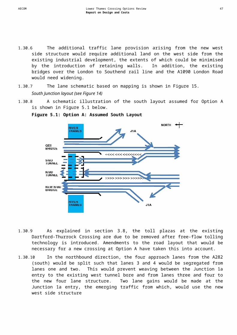
AECOM Lower Thames Crossing Options Review 49Report on Design and Costs
Bridge – Structure Description (see Figure 27)
1.39.7 As noted above, the air draught required by the PLA at Option B is 70m. This requirement is higher than at Option A in reflection of the proximity of the deep water jetty for grain cargoes. The constraint imposed by the jetty and the wide navigable river channel close to an acute bend in the River Thames at this location, means that a longer bridge span would be needed to allow for safe operation of large ships than at Option A. The main piers would need to be set back sufficiently to avoid vessel impact. It would be necessary to carry out a probabilistic analysis taking into account vessel movements, the deviation angle of the river and components of current parallel and perpendicular to the vessel path to confirm that the selected location of main piers would fulfil the acceptance criteria against bridge damage as a result of a ship impact. The analysis would also determine the ship impact criteria for the design of pier foundation. For cost estimating purposes, caisson foundations of similar ship impact resistance as the existing QEII foundations have been assumed.
1.39.8 The span arrangement for the cable stayed bridge, subject to the outcome of the above ship impact analysis, has been assumed to comprise a main span of 700m and two side spans of 280m. As for Option A, for reasons of constructability and efficient behaviour in service, the back spans would be sub-divided into three-span continuous structures by introducing two intermediate pendel piers. Following best practice, the full length of the bridge, 1.26km, would be kept within a straight section of the horizontal alignment. The standard approach spans would be 50m, reduced marginally in the curved section of the viaduct to avoid excessive deck cantilever when using straight girders. The overall length of the bridge and viaduct would be 5.3km.
1.39.9 The overall deck width would be 28.1m comprising 2x7.3m carriageway, central reserve 2.5m, 1.0m hard strip on both sides of each carriageway, 2.5m verge, 0.6m cable anchorage and 0.4m for deck furniture on each side of the deck. The deck girder arrangement is described in Section 3.6. The height of the pylon would need to be 169m above the deck level to enable efficient use of the stay cables supporting the midspan region of the deck.
1.39.10A wider deck would be required for Option B than the existing QEII Bridge or a new bridge at Option A due to Option B’s greater altitude. This could lead to Option B exhibiting greater vortex shedding, with the bridge experiencing higher movement and fatigue loading. This may be exacerbated by the need to use wind shielding. Wind tunnel testing would need to be carried out to investigate any adverse effects of vortex shedding and ensure the deck is not prone to divergent amplitude phenomenon. Modification of the deck cross-section to profiled steel boxes or simple addition of wind appendages on the deck may be necessary to endure aerodynamic stability. Wind tunnel testing and potential modification the cross-section has been taken into account in the cost estimate for this option.Bored Tunnel – Road Design (see Figures 25 & 26)
1.39.11From the south, the assumed illustrative route for a bored tunnel curves to the west and crosses the Kent suburban rail line and the A226 before passing through the Northfleet Industrial Estate and over the HS1 rail line on a viaduct
1.39.12It has been assumed that a bored tunnel crossing of the River Thames would comprise a ramped descent on the Swanscombe Peninsula with a straight alignment under the River Thames. On the Tilbury side of the river the tunnel would extend under the London to Southend rail line to the north side of the Thameside Junior and Infants School playing field, curving around the edge of an industrial area and then alongside a retail park. The route would then ascend onto a viaduct over the A1089.
1.39.13On the north side of the River Thames it has been assumed that the route diverges from the A1089 and curves and rises across arable land to cross back over the A1089. From there, the
AECOM Lower Thames Crossing Options Review 50Report on Design and Costs
route would drop into tunnel and pass beneath the London to Southend rail line serving Tilbury and the western boundary of the Port of Tilbury. The initial cut-and-cover section of the tunnel would impact the north-western corner of the industrial estate to the north of Tilbury Docks and the school playing fields to the west of this industrial estate.
Bored Tunnel – Structure Description (see Figure 29)
1.39.14A bored tunnel crossing would be composed of two bored tunnels with an internal diameter of approximately 11m, each containing two lanes. It has been assumed that each tunnel would be separated by approximately two tunnel diameters. Tunnel diameters have been based on two 3.5m wide lanes and 1.0m verges either side but no hard-strip through the tunnel. The overall length of each bore would be approximately 2.2km. The maximum depth below the river bed to the carriageway would be approximately 30m, equating to a ground cover to the tunnel crown of about two tunnel diameters.
1.39.15Gradients for the approach tunnels have been assumed at 3% to the north to pass under the suburban rail line and 4% to the south to pass over the HS1 tunnel. It is assumed that axial fans would be required to move the required volumes of air both to prevent the build up of dangerous levels of pollutants during normal service and to control smoke build-up in the event of a fire. Two shafts at each end of each tunnel are envisaged to house the axial fans, each with inlet and exhaust stacks. Other major facility buildings include those for power supply sub-stations, pump room and tunnel control centre.
1.39.16The exact spatial and MEICA requirements for a bored tunnel would need to be determined at the feasibility and preliminary design stages of the project.Immersed Tunnel - Road Design (see Figures 22 to 24)
1.39.17It has been assumed that an immersed tunnel would traverse the River Thames in a straight line between Grays on the north bank and the Swanscombe Marshes on the south bank.
1.39.18The north approach to the immersed tunnel would lie inside the western boundary of the Port of Tilbury but away from the principal port infrastructure. Grays Beach Park lies immediately to the west of the crossing approach. The location of the London to Southend rail line serving Tilbury necessitates that the crossing structure would need to extend under and beyond the north of this rail line. The road has therefore been assumed to pass beneath the rail line in cutting with retaining wall sides before descending into a ‘cut-and-cover’ tunnel section, which would in turn link into the immersed tunnel beneath the river.
1.39.19The south approach would cross the Broadness Salt Marsh to the east of the Northfleet Industrial Estate before sweeping to the east, passing over the HS1 rail line. The road has been assumed to drop firstly into cutting with retaining wall sides followed by a ‘cut-and-cover’ tunnel linking with the immersed tunnel.Immersed Tunnel – Structure Description (see Figure 28)
1.39.20It has been assumed that an immersed tunnel constructed across the river would link into ‘cut-and-cover’ tunnel sections on both shores. The four-lane carriageway would be split into a pair of two 3.5m wide lanes with 1m verges either side contained within separate cells, with an emergency egress passageway cell running lengthwise between them.
1.39.21The design provides for the road to pass beneath London to Southend rail line in cutting with retaining wall sides before descending into a ‘cut-and-cover’ tunnel to link into the immersed tunnel beneath the river. The feasibility of the rail crossing would need to be confirmed; indeed a more in-depth study may show that an overbridge of the rail line can be achieved.

AECOM Lower Thames Crossing Options Review 51Report on Design and Costs
1.39.22Gradients for the approach tunnels have been assumed at 3.5%. It is assumed that axial fans will be required to move the required volumes of air both to prevent the build up of dangerous levels of pollutants during normal service and to control smoke build-up in the event of a fire. Two separate buildings at each end of the tunnel are envisaged to house the axial fans, each with inlet and exhaust shafts. Other major facility buildings include those for power supply sub-station, pump room and tunnel control centre.
1.39.23The exact spatial and MEICA requirements for an immersed tunnel would need to be determined at the feasibility and preliminary design stages of the project.
1.40 Buildability
1.40.1 The buildability of a new crossing at Option B would be affected by many factors:
- Passage of vessels along the Thames.
- Port of Tilbury on the north bank of the Thames with associated jetties.
- Rail lines and roads crossing the site.
- Grade separated junctions at each end.
- Overhead electricity lines and other major services.
- Industry and commercial activities.
- Proximity to south east Grays.
- Ebbsfleet station car park.
- Development sites. Bridge
1.40.2 The assumed illustrative route for a new crossing at Option B runs through several constraints on both sides of the Thames. These constraints include developments of residential units, schools and a retail park, suburban rail lines and the HS1 rail line. Overhead electricity lines also act as a constraint as they cross the River Thames. There are also a number of sites that have been identified for industrial and commercial employment development.
1.40.3 Site access is available from both sides of the River Thames, but the proximity of the above constraints to the highway corridor means that some impact is inevitable for construction activities. The ground conditions are weak on both sides of the river, and if a bridge was provided at Option B then foundations would be needed in the marsh area on the south of the river. It is likely that causeways would need to be constructed to facilitate the installation of piles for the foundation. It might be possible to install some of the piles on the riverside using jack-up barges.
1.40.4 The piers, crossheads and superstructure for the approach spans could be constructed working progressively from each abutment toward the back span as described for Option A (see paragraph 1.31.4). Bored Tunnel
1.40.5 Specific issues for a bored tunnel crossing for Option B are discussed below. These are additional to the general issues identified in Section 3.7:
- Network Rail is likely to impose stringent criteria on the design of a tunnel beneath the London to Southend rail line. The nature of the rail crossing would need to be discussed in detail with Network Rail to obtain the necessary approvals.

AECOM Lower Thames Crossing Options Review 52Report on Design and Costs
- To enable the marshland to support the tunnel approach structures there could be a need for significant ground improvement works.
- The land on both banks surrounding the crossing location is low lying. Retaining walls along the sides of the approaches would therefore extend until the road elevation exceeded the design flood level. If the extent of such walls became impracticable then the installation of flood doors might be necessary.
- On the south side of the River Thames the crossing would interrupt an existing drainage ditch. Solutions to prevent this ditch flooding the road and tunnel would have to be developed. We have assumed that the ditch would be re-routed directly to the river together with construction of a drainage lagoon to collect and store flood waters (this appears to be the solution adopted by the nearby HS1 rail line).
Immersed Tunnel
1.40.6 Specific issues for an immersed tunnel crossing for Option B are discussed below. These are additional to the general issues identified in Section 3.7:
- During construction of an immersed tunnel there would be an impact on the passage and berthing of shipping along the river. The assumed crossing point for an immersed tunnel is near an acute bend in the river, where ships would be expected to need greater lateral clearance. Also, the nearby grain terminal may have restricted access due to the construction operations.
- The openness of the site on the south bank of the River Thames makes the on shore excavation for the southern approach structures a possible site for fabrication of the tunnel elements. The soft nature of this marshland could make robust temporary works a significant challenge.
- The land on both river banks surrounding the crossing location is low lying. As in the case of a bored tunnel flood protection measures at the tunnel portals would therefore need to be considered.
- On the south side of the River Thames the assumed crossing alignment would interrupt an existing drainage ditch, as discussed for a bored tunnel (see paragraph 6.7.9).
- On the north shore the space available for construction of the approach structures is limited. Access to the construction site would probably have to be through the Port of Tilbury and would need to be negotiated with the port operator.
South Road Section (bridge, bored tunnel or immersed tunnel)
1.40.7 At the A2 Ebbsfleet Junction, temporary road diversions would be needed to maintain traffic flows to Ebbsfleet International and the other local routes. Early construction of a dumb-bell roundabout junction near to the station car park would enable some of the new connections to be off-line and so ease buildability issues.
1.40.8 Multiple bridge crossings of suburban rail lines, the A226 and the HS1 rail line, as well as the former chalk quarries, would require a viaduct. Part of the viaduct would cross the HS1 line at a high skew (for the tunnel crossings). Potentially this would need to built offsite and installed to minimise disruption to the rail line beneath.North Road Section (bridge, bored tunnel and immersed tunnel)
1.40.9 Most of the buildability issues relate to the crossing structures. For the tunnel options, a viaduct over the A1089 could be built whilst maintaining traffic flows. Alterations to the Marshfoot

AECOM Lower Thames Crossing Options Review 53Report on Design and Costs
Interchange could be made relatively easily. However special earthworks construction measures would be required over the peat on Tilbury Marshes.
1.41 Deliverability
1.41.1 Particular Issues that could affect the deliverability of a new crossing at Option B are:
- Crossing of the former, now demolished, port related site may be affected by future development plans for the Port of Tilbury.
- The proposed Ebbsfleet Valley development site.
- Visual impacts of a bridge on the Grays housing, school and recreational areas.
1.41.2 We would expect that a future scheme design could be developed to address these issues, subject to the benefits being judged to outweigh the impacts likely to be imposed on these constraints.
1.42 Estimated Costs
1.42.1 Risks identified with the potential to affect construction costs include:Generic Risks
- Access to site on Essex side may be restricted.
- There may be unforeseen adverse ground conditions.
- Third party land and compensation costs may be higher than anticipated including re-development of the affected area of the Port of Tilbury.
- Soft ground on Tilbury marshes may be worse than considered.
- Improvements may be needed to the trunk and local road network.Bridge
- Bridge deck may need to be widened due to hard shoulder requirements or for other reasons.
- Navigation (air draught) requirements may increase.
- Construction of piers may constrict shipping movements.
- Greater cost may be incurred due to effect of electricity lines.
- Construction space for a viaduct on Essex side of the River Thames may be restricted.
- Additional 3rd party claims may be made in response to bridge impacts such as loss of amenity, accessibility, noise and construction disruption.
Immersed Tunnel - Construction may impact on shipping movements.
- Space available for construction of the tunnel may be restricted.
- The depth of the tunnel may need to increase.
- The length of the tunnel may need to increase to reduce land taken from playing fields at the junior school on the Essex side of the River Thames.
- There may be a lack of space nearby for tunnel unit casting yard.
AECOM Lower Thames Crossing Options Review 54Report on Design and Costs
Bored Tunnel
- Space to install tunnel boring machine may be restricted.
- The depth of the tunnel may need to increase.
- The length of the tunnel may need to increase to reduce land taken from playing fields at the junior school on Essex side of the River Thames.
1.42.2 As described in Chapter 4, an allowance for these risks has been included in cost estimates.
1.42.3 Table 6.1 summarises the most likely cost estimates for a new crossing with two lanes in each direction (bridge, immersed tunnel and bored tunnel) and associated link roads25 at Option B. Table 6.1: Option B: Most likely estimated capital costs for new crossing structures and link roads with two lanes in each direction
Bridge Immersed Tunnel Bored TunnelCrossing structure £1.68bn £1.83bn £1.72bnLink Roads £0.10bn £0.19bn £0.45bnTotal £1.78bn £2.02bn £2.17bn
1.42.4 Table 6.2 provides the range of minimum, most likely and maximum total cost estimates for a new crossing with two lanes in each direction at Option B. These figures include the costs of all infrastructure needed to link the new crossing structure with the existing road network. Table 6.2: Option B: Total cost ranges for new crossings with two lanes in each direction
BridgeMin Most Likely Max
£1.63bn £1.78bn £2.06bnImmersed Tunnel
Min Most Likely Max£1.85bn £2.02bn £2.34bn
Bored TunnelMin Most Likely Max
£1.98bn £2.17bn £2.50bn
1.42.5 Table 6.3 provides the most likely cost estimates for a new crossing structure with three lanes in each direction at Option B. These figures do not include the costs involved with linking a new crossing into the existing road network.Table 6.3: Option B: Most likely estimated capital costs for new crossing structures with three lanes in each direction
Bridge Immersed Tunnel Bored TunnelCrossing Structure £2.11bn £2.34bn £2.71bn
25 As described above, all link road infrastructure has been designed to all purpose dual carriageway standards.

AECOM Lower Thames Crossing Options Review 55Report on Design and Costs
1.42.6 The range in cost estimates between structures for a crossing providing two lanes in each direction is relatively small and lies within the margin of error in the estimating process. The estimate for the bridge is lower than the estimates for the tunnels. However cost estimates for tunnel structures are closer, in relative terms, to the cost estimate of a bridge at Option B than the estimates for the tunnels and the bridge are at Option A. This is because the air draught required for a bridge at Option B is significantly higher than at Option A, increasing the length of the bridge structure beyond that which would otherwise be required. Additional costs associated with the northern connection across soft ground on Tilbury marshes would be similar for each of the crossing alternatives. Significant viaducts would be needed on both sides of the River Thames for both types of tunnel structures. Higher costs would arise for the bored tunnel structure due to the long and high viaduct over the rail line and A226 at Swanscombe.
1.42.7 As with Option A, the estimated cost of a six lane bridge structure is again less than the corresponding estimates for tunnel structures. The most expensive six lane crossing structure is again the bored tunnel.
AECOM Lower Thames Crossing Options Review 56Report on Design and Costs
1.43 Introduction
1.43.1 This Chapter explains how the methodologies described in Chapters 2-4 used to identify constraints, develop conceptual designs, and produce cost estimates, were applied to produce conceptual designs and cost estimates for a new crossing at Option C.
1.44 Assumed Illustrative Route
1.44.1 A new crossing at Option C would cross the River Thames to the east of the towns of Gravesend and Tilbury Connections would be made to the A2/M2, just south of Shorne in Kent, and to the M25 (between junctions 29 and 30) to the north of North Ockendon in Essex. It would also connect to the Orsett Cock Interchange on the A13 via a free flow trumpet interchange and short length of dual carriageway road. The assumed illustrative route for a new crossing at Option C is 21km long and is shown on Figure 30.
1.44.2 The assumed illustrative route for Option C broadly follows the corridor identified in the 2009 report. The exceptions to this are set out in paragraphs 7.2.3 to 7.2.7 below. Connection to A2
1.44.3 The assumed illustrative route has been moved closer to Shorne to allow the conceptual junction layout at the connection with the A2 to comply with design standards set out in the DMRB.River Thames Crossing
1.44.4 On the south side of the River Thames, the assumed illustrative route has been assumed to be positioned at the western edge of the internationally recognised Thames Estuary and Marshes Ramsar site. Movement from west side to east side at Orsett
1.44.5 At Orsett, the assumed illustrative route for a new crossing at Option C has been moved west to allow construction of a separate junction offset from the A13. This would permit a connection to a modified Orsett Cock junction on the A13. Without this separate connection, the Orsett Cock junction would need to be altered and would effectively move eastward to allow direct interchange connections between the crossing route and the A13. However, this would reduce the allowable traffic weaving length to the next junction on the A13 (to the A1089) and lead to unacceptably low road standards.
1.44.6 Moving the assumed illustrative route west from the A13 junction would cause the new road to pass the west side of Orsett rather than the east side, as shown in the 2009 study. Connection to M25
1.44.7 A free –flow connection to the M25 has been assumed. This would involve moving the new junction approximately two km south of the position shown in the 2009 Study.
1.45 Review of Environmental Constraints
Air quality (see Figure 1)
1.45.1 AQMAs have been declared for the whole of London Borough of Havering, for the A2 leading to the assumed crossing by Gravesham Borough Council and for Maidstone by Maidstone Borough Council near the M2- M20 link (see Figure 1).
6 Option C

AECOM Lower Thames Crossing Options Review 57Report on Design and Costs
1.45.2 If these AQMAs are still in existence in the opening year, they could be a significant environmental constraint.
1.45.3 The assumed illustrative route for a new crossing at Option C passes through largely rural areas but some small areas are lightly to moderately populated. An initial assessment shows that to avoid adverse effects, the new road should be located at least 40m from the road centre to the nearest properties.
1.45.4 The assumed illustrative route passes through the South Thames Estuary and Marshes SSSI, Thames Estuary and Marshes Ramsar site and SAC and Shorne and Ashenbank Woods SSSI (see Figure 2), all of which contain features which are sensitive to air pollution. The effect of increased nitrogen deposition on these features associated with a new crossing at Option C would therefore present a potential constraint. If Option C was taken forwards then existing and future nitrogen deposition rates likely to affect these ecosystems would need to be predicted and the effect of Option C assessed.Biodiversity (see Figures 2 and 3)
1.45.5 The following biodiversity constraints have been identified for Option C (see Figures 2 and 3):
- Thames Estuary recommended MCZ.
- Mudflat habitat on the northern and southern banks of the River Thames.
- Thames Estuary and Marshes Ramsar site.
- South Thames Estuary and Marshes SSSI.
- Thames Estuary and Marshes SPA.
- Coastal and Floodplain Grazing Marsh habitat to the north west of Orsett and to the north of south of the Thames.
- Reed bed habitat to the south of the Thames.
- Shorne and Ashenbank Woods SSSI, located adjacent to the assumed illustrative route for Option C.
- Cobham Woods SSSI, located approximately 0.2km to the south of the assumed illustrative route for Option C.
- Great Crabbles Woods SSSI, located approximately 0.4km to the east of the assumed illustrative route for Option C.
- Ancient Woodland at a number of sites (Claylane Wood and sites within Shorne and Ashenbank Woods SSSI and Great Crabbles Wood SSSI are likely to be affected).
1.45.6 The most significant environmental feature affecting a river crossing at this location is the Thames Estuary and Marshes Ramsar site and South Thames Estuary and Marshes SSSI. The Thames Estuary and Marshes SPA is also located approximately 200m to the east. These sites emphasise the importance of the area for birdlife.
1.45.7 Any future decision on taking forward a bridge or immersed tunnel as the main structure for a crossing at Option C would need to take account of both the physical construction impact and the longer-term impact on bird populations in the area. A bored tunnel would have the least environmental impact in relation to these areas.
1.45.8 Providing a new crossing at Option C could also involve habitat loss of the Shorne and Ashenbank Woods SSSI, which is designated for its ancient and plantation woodland. This could present a
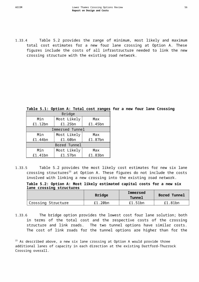
AECOM Lower Thames Crossing Options Review 58Report on Design and Costs
significant constraint, as this habitat cannot be re-created immediately in another location since it takes many decades to establish.Heritage of Historic Resources (see Figure 4 and Appendix 3)
1.45.9 The following significant constraints relating to the heritage of historic resources have been identified for Option C (see Figure 4):
- Several Scheduled Monuments within 500m of the assumed illustrative route of a new crossing at Option C. The following Scheduled Monuments within 50m are of particular significance in terms of potential effects from the alignment:
- Orsett Neolithic causewayed enclosure, Iron Age settlement and Anglo-Saxon cemetery (Scheduled Monument) (Sites 74, 76, 100 and 695).
- Orsett Cock settlement including sunken featured buildings, post holes, pits and ditches (Scheduled Monument) (Site 731).
- West Tilbury earthwork fortification consisting of a number of scheduled earthworks, possibly Anglo-Saxon or medieval in date (Scheduled Monument) (Site 852).
- Bronze or Iron Age spring field style enclosures near Orsett, (Scheduled Monument) (Site 908).
- Cobham Hall Park, a Grade II* Registered Park and Garden: late 18th and early 19th century ornamental gardens and pleasure grounds laid out by Humphry Repton (Sites 322 and 894).
- Grade II* listed buildings including the Church of St Mary Magdalene, North Ockendon (Sites 874 and 858) and the former Church of St James, West Tilbury (including a coffin which is also part of the church listing) (Sites 811 and 883).
- Route of a Roman road (Site 909) – the state of preservation of this site is uncertain and would require further investigation to establish at a future stage.
- Several Conservation Areas within 500m of the Option C alignment including North Ockenden, Orsett, West Tilbury, Chestnut Green (Shorne) and Shorne (Village).
- Several Grade II listed buildings within 50m of the Option C alignment (see below for further details).
- Several sites of known archaeology within 50m of the Option C alignment (see below for further details).
1.45.10There are a number of listed buildings within 500m of the assumed illustrative route for Option C. The following Grade II listed buildings within 50m are of particular significance:
- High House, Chadwell (an eighteenth century timber framed house) (Site 8) (it should be noted that this building is on the Building at Risk register).
- Filborough farmhouse (Site 132).
- Granary at Little Filborough Farm (Site 139).
- Church of St Mary (Site 469).
- West Tilbury Hall (Site 662).
- Barn to north of West Tilbury Hall (Site 663).
- Post House, shop (Site 686).
- Early 19th century mill house, Grade II listed (Site 803).
AECOM Lower Thames Crossing Options Review 59Report on Design and Costs
1.45.11Lastly, there are several known archaeological sites within 500m of the assumed illustrative route for Option C. Sites within 50m, which could be a major significant constraint, are listed below.
- Roman hut circles near the west boundary of the parish at East Tilbury (Site 503) – physical impacts on this site should be avoided. If this were not possible, evaluation and excavation of surviving features would be required at a future stage. The estuarine conditions may lead to organic remains being present and significant excavations costs.
- Iron Age trackway at High House Lane, Chadwell St Mary (Site 768).
- Multiphase archaeological remains (cropmarks) near Orsett, close to Barrington's Farm and Loft's Farm ranging in date from the Neolithic to the Roman periods (Site 828).
- Holme Farm (Bulphan fen pit, cemetery, burial and settlement) (Site 843).
Landscape / Townscape (see Figure 5)
1.45.12The following landscape constraints have been identified for Option C (see Figure 5):
- Kent Downs AONB.
- Cobham Park Registered Park & Garden.
- Conservation Areas (within 1km of the assumed illustrative route for Option C) including North Ockenden, Orsett, West Tilbury, Queens Farm (Shorne), Chestnut Green (Shorne), Shorne (Village), Abbey Gate.
- Listed Buildings within 500m of the assumed illustrative route for Option C.
- Scheduled Monuments within 500m of the assumed illustrative route for Option C.
- Ancient Woodland.
1.45.13The Kent Downs AONB and Cobham Park Registered Park and Garden are both nationally designated areas of landscape value and could present significant constraints to a new crossing at Option C.
1.45.14If Option C were taken forwards then careful consideration would need to be given to screening the new road at the detailed design stage i.e. by using the existing topography or woodland and by avoiding local landscape features, which contribute to the setting of the designated landscape.
1.45.15Visual receptors include residential receptors in Orsett, Chadwell St. Mary, East Tilbury, the eastern edge of Gravesend, Shorne and Strood. Other receptors include recreational users of public rights of way (including the North Downs National Trail), recreational areas such as East Tilbury, Shorne Country Park and Shorne Marshes and the River Thames. There could also be visual impacts, relating to changes in the character of views and visual amenity of visual receptors, because of the introduction of traffic and/or highway related structures in views.Noise (see Figure 6)
1.45.16Sensitive receptors for noise include residential properties in Shorne Ridgway, Chalk, Chadwell St Mary and Orsett. Receptors may experience a significant increase in road traffic noise.
1.45.17To avoid significant impacts, new sections of road would need to be located at least 130 metres from sensitive receptors. Noise barriers and low noise road surfaces options could be implemented to control adverse changes in noise levels.
1.45.18Noise action planning areas have been identified along the A2 to the south of Gravesend and the M2 at Rochester and could be affected by a new crossing at Option C. The impact of noise

AECOM Lower Thames Crossing Options Review 60Report on Design and Costs
associated with a new crossing on these areas would need to be considered further if Option C was taken forward.
1.45.19To the east of Gravesend, the assumed illustrative route for a new crossing at Option C passes through areas that are not directly affected by existing sources of road traffic noise and are potentially moderately tranquil. In comparison, much further to the east, the north Medway area could be described as most tranquil. Similarly, on the northern side of the River Thames, the assumed illustrative route passes through areas not directly affected by existing sources of road traffic noise. The proximity of any new roads to such areas would need to be considered carefully if Option C was taken forward.Water environment
1.45.20The water environment constraints listed in paragraphs 1.27.13 to 1.27.15 above apply to Option C. In addition, Option C could affect the Mar Dyke and West Tilbury Main.
1.45.21This option is affected by flood zones (see Figure 7); appropriate drainage works might have to be carried out if Option C was taken forwards.Summary
1.45.22A number of significant environmental constraints have been identified that would need to be assessed further if a decision was taken to provide a new crossing at Option C. In particular, any decision to develop a future proposal that could affect the Thames Estuary and Marshes Ramsar site would involve the preparation of an Appropriate Assessment.
1.46 Review of Planning Constraints (see Figures 8b and 8c)
1.46.1 The whole of the assumed illustrative route for a new crossing at Option C lies within Green Belt. North of the River Thames the assumed illustrative route would pass through land designated as Green Belt throughout its entire length within Thurrock before passing into land designated as Green Belt in Havering and connecting to the M25. South of the River Thames, the assumed illustrative route would pass through land designated as Green Belt in Gravesham before connecting to the A2/M2.
1.46.2 The only known planned developments that could act as constraints are south of the Thames within Gravesham.
1.46.3 One site (ref GR08) under consideration lies to the north east of Gravesend, bounded by urban land-uses fronting Lower Higham Road to the South and the North Kent Line to the North on land known as Great Clane Lane Marshes.
1.46.4 The South of Astra Drive (GR10) and East of Thong Lane (GR09) development sites adjoin the existing Gravesend urban area and are less likely to pose a significant constraint. However, if Option C were taken forward, consideration would need to be given to the proximity of associated link roads to a possible revised edge of town.
1.46.5 There are no known development constraints north of the River Thames.Summary
7.4.5 A number of planning constraints have been identified that would need to be assessed further if a decision was taken to provide a new crossing at Option C.
1.47 Review of Engineering Design Constraints
Navigation
7.5.1 The PLA has advised that the upper surface of an immersed tunnel at Option C would need to be below the existing riverbed. A bridge structure would need to have an air draught of 70m above

AECOM Lower Thames Crossing Options Review 61Report on Design and Costs
Mean High Water Springs. The central span would need to provide sufficient width for the navigation channel and access to the adjacent jetties. Rail
7.5.2 The HS1 rail line south of the River Thames and the Kent suburban rail line both act as constraints to the assumed illustrative route for a new crossing at Option C.
1.47.1 The assumed illustrative route for a new crossing would cross the Tilbury Loop of the London to Southend rail line approximately 2km north of the River Thames. The assumed illustrative route would run close to the Upminster to Grays branch line near to the new junction with the M25.Roads
1.47.2 Option C is crossed by main trunk and other principal roads including the A2(T) and A226 in Kent and the A13 and M25 in Essex. There are also many local roads, which will require alterations to prevent severance.Utilities / Services
1.47.3 Overhead electricity lines on the east side Tilbury Power Station could be affected by a new crossing at Option C. Other overhead lines would be crossed further north towards the M25. There are, in addition, local networks of utility services linking communities on both sides of the River Thames that would be crossed by the illustrative route.
1.47.4 Colewood underground reservoir is located close to the southern connection junction on the M2.Ground Conditions/Geotechnics
1.47.5 The area covering Route Option C is widespread hence ground conditions vary significantly. At the crossing site, both sides of the River Thames are covered by approximately 10m of soft material over granular deposits over chalk. On the north side of the River Thames, there are also large areas of landfill, where made ground may be expected (see Figure 8e).
1.47.6 As for Options A and B, the founding stratum is likely to be Chalk and any capacity of piled foundations generated in the superficial deposits is likely to be ignored. Summary
1.47.7 A number of engineering design constraints have been identified that would need to be assessed further if a decision was taken to provide a new crossing at Option C.
1.48 Assumed Road and Crossing Structures
Southern Connection to A2/M2 (see Figure 31)
1.48.1 The southern connection point would coincide with the existing free flow interchange of the A2 and M2 and the A289 (Wainscot Northern Bypass). Adding a further free-flow connection from the assumed illustrative route for a new crossing at Option C would provide a further layer of weaving connector roads in an already congested site. The connection site is also constrained by:
- The route of the HS1 rail line running parallel to the A2/M2 roads.
- Ancient Woodland on the north side of the A2 with SSSI status.
- Colewood Reservoir (underground) next to the M2.
- Houses at the west end of Strood.
- Shorne Wood Country Park on the north side of the A2.

AECOM Lower Thames Crossing Options Review 62Report on Design and Costs
- An AQMA along the A2 (see Figure 1).
- Cobham Park Registered Park and Garden.
- Heritage conservation area at Shorne.
1.48.2 Figure 31 shows the conceptual layout for a free-flow link to the A2 west and the M2 east.
1.48.3 The points at which connections to the A2 west has been assumed, would enable the minimum standard weaving length set out in the DMRB to be achieved. Extensive structures would be required to reduce land take, avoid the HS1 rail line and to pass over the A2, Halfpence Lane Junction and Brewers Road. Alternative access arrangements would be required to the Inn on the Lake Hotel and Shorne Wood Country Park.
1.48.4 For the connection to the M2, east free-flow connections would be phased in with the existing M2 Junction 1 slip roads. Extensive, highly skewed, structures would be required and a third level would be added to the interchange between the M2 and the new road.
1.48.5 Impacts on Ancient Woodland and the Country Park may mean that the roads need to be bored in tunnel underneath. The feasibility of such a design would need to be examined further outside this study.
1.48.6 The link roads from the A2 junction would merge to form the main route leading to a new crossing at Option C just to the west of Shorne.Main Route (see Figures 30 to 37)
1.48.7 The assumed illustrative route for a new crossing at Option C follows a north-westerly direction starting from the south. It has been designed as a two lane dual carriageway with a design speed of 120 km/h. The design speed has been reduced to 85km/h at the crossing structure itself (for both bridge and tunnel). A higher design speed would have resulted in a longer bridge or tunnel and would have made the crossing excessively long and costly. This approach follows the same design principles applied in respect of Option B.
1.48.8 From the start of the dual carriageway, to the west of Shorne, the assumed illustrative route crosses mainly arable land to the east of Chalk. On the approach to the A226 Gravesend Road, the vertical alignment of the route would change depending on the type of crossing of the River Thames. The vertical alignment options for the alternative crossing structures are described below.
1.48.9 Further north, the assumed illustrative route generally passes through arable land to the east of Chadwell St Mary with a succession of curves. This section of the route has been assumed to be generally in cutting. It would pass over a severed Cooper Shaw Road26 and under Rectory Road at West Tilbury. At this point, the route would be within a conservation area. Further north, the assumed illustrative route passes under Linford Road, over Brentwood Road and under overhead electricity lines.
1.48.10The assumed illustrative route veers west of the corridor indicated in the 2009 Study in the A13 to Orsett area. The driver of this change is the sub-standard weaving length between the Baker Street Interchange (A1089) and the Orsett Cock junction on the A13. Introduction of a new crossing over the Orsett Cock Interchange would lead to a significant extension of the gyratory to the West and compromise the already sub-standard weaving length available. This problem can be alleviated by providing an offset junction as indicated on Figures 39 and 47. An additional arm would be added to the Orsett Cock Junction gyratory leading to a free-flow trumpet junction on Route C. Some widening of the gyratory would be needed but not on the same scale as for a
26 Alternative route via Rectory Road assumed.
AECOM Lower Thames Crossing Options Review 63Report on Design and Costs
three level junction requirement in the original route C. It is assumed that the following improvements would be required at the Orsett Cock:
- Larger and wider signalised gyratory.
- Widened east bridge.
- New west bridge.
- Widened slip roads.
1.48.11The assumed illustrative route then descends into a cutting to pass under the A1013 Stanford Road and the A13 and has been assumed to be in cutting where it passes to the west of Orsett. This route would affect the eastern fringe of a Schedule Monument27. It would be possible to move the new road further east but this would bring it closer to houses in Orsett. Further, more detailed studies would have to be undertaken to determine the relative impacts.
1.48.12Further north, the assumed illustrative route would pass under High Road in cutting and then over Fen Lane, which has been assumed to be re-aligned in an underpass. Parallel connector roads from Fen Lane Underpass would reduce severance for users of Green Lane
1.48.13North of Orsett, the route would emerge from cutting and has been assumed to be situated on a low embankment along the edge of Orsett Fen, which is in a flood risk area.
1.48.14For the next five kilometres, the new road would slowly rise and curve to the west through arable land to north of North Ockendon; generally at grade for the first four kilometres and on embankment for the remaining one kilometre. A diversion to North Road and connections to enable non-motorway vehicles to exit and enter before the new junction with the M25 have been assumed.Northern Connection to M25
1.48.15Our conceptual designs assume that a new junction on the M25 would only provide connectivity to the north. It has been assumed that traffic wishing to access the crossing link from the south would follow the A13 to the junction at Orsett.
1.48.16The westbound carriageway of the new road would connect to the northbound carriageway of the M25 via a free flow link road, requiring successive rail-M25-rail bridge crossings to make the connection without adversely affecting the B1421 over the M25 and the adjoining properties. Further, more detailed, studies may provide more optimal solutions.
1.48.17The southbound carriageway of the new road would depart from the M25 southbound carriageway using a standard motorway exit design. Bridge – Road Design (see Figures 32 & 33)
1.48.18We have assumed that the northbound approach to a bridge crossing at Option C would be in a cutting, passing under a new bridge carrying the A226 Gravesend Road. The approach viaduct to a bridge crossing the River Thames would cross Lower Higham Road, the Kent suburban rail line and the disused canal without need for alterations to be made. The Thames Estuary and Marshes Ramsar and SSSI site would also be crossed at its western margins on the Kent side while on the approach viaduct.
1.48.19A bridge crossing would need to allow a 70m navigable air draught above High Water Springs level over the River Thames in order to meet PLA navigation requirements.
27 Enclosures and Iron Age settlement.
AECOM Lower Thames Crossing Options Review 64Report on Design and Costs
1.48.20On the Essex side, the assumed illustrative route would descend over the West Tilbury Marshes. Three sets of overhead electricity lines could be affected by the bridge and might need to be diverted. The end of the bridge would be just north of the London to Southend rail line.Bridge - Structure Description (see Figure 42)
1.48.21As noted above, the air draught required by the PLA for a bridge crossing at Option C is 70m above Mean High Water Spring level. This requirement reflects the proximity of Tilbury Docks. The navigable channel is very wide, and so the main bridge piers would need to be set back sufficiently to avoid vessel impact. A probabilistic analysis taking into account vessel movements would need to be carried out to verify the acceptability of assumed pier locations and to determine the ship impact criteria for the design of pier foundation. For cost estimating purposes, caisson foundations of similar ship impact resistance as the existing QEII bridge foundations have been assumed.
1.48.22The assumed span arrangement for a bridge crossing at Option C comprises a main span of 800m and two side spans of 320m. As described in Option A, for reasons of constructability and efficient behaviour in service, the back spans are assumed to be sub-divided into three-span continuous by the introducing of two intermediate pendel piers. Approach spans would be 50m. The overall length of the bridge and viaduct would be 4.3km.
1.48.23The overall deck width would be 28.1m; comprising 2x7.3m carriageway, 4.5m central reserve, 1.0m hard strip, 2.5m verge, 0.6m cable anchorage and 0.4m for deck furniture on each side of the deck. The height of pylon would need to be 192m above the deck level to enable efficient use of the stay cables supporting the midspan region of the deck.
1.48.24The wider deck required for Option C in the open country side at higher altitude may exhibit greater vortex shedding than the existing QEII Bridge. If a bridge at Option C was taken forwards it would be necessary to undertake wind tunnel testing to demonstrate the aerodynamic stability of the structure with wind shielding. Modification of the deck cross-section to profiled steel boxes or simple addition of wind appendages on the deck might be necessary. Wind tunnel testing and potential modification to the cross-section have been taken into account in the cost estimate for this option.Bored Tunnel – Road Design (see Figures 40 & 41)
1.48.25The northbound approach to a bored tunnel has also been assumed to be in a cutting, passing under the A226 Gravesend Road and proceeding under Lower Higham Road, the Kent suburban rail line, the disused canal28 and the River Thames. On the Essex side, the assumed illustrative route is on embankment and passes over the London to Southend rail line. Further north, the assumed route is the same as for the other crossing structure options.Bored Tunnel – Structure Description (see Figure 44)
1.48.26We have assumed that a bored tunnel at Option C would cross the River Thames in a straight line between East Tilbury marshes on the north bank (to the east of the Tilbury Power Station) and the Thames Estuary and Marshes Ramsar / SSSI on the south bank. The crossing would be composed of two bored tunnels with an internal diameter of approximately 11m, each containing two carriageway lanes, separated by approximately two tunnel diameters. The tunnel diameter has been based on two 3.5m wide lanes and 1.0m verges either side but no hard-strip through the tunnel. The overall length of each bore would be approximately 2.75km. The maximum depth below the river bed to the carriageway would be around 30m, equating to a ground cover to the tunnel crown of about two tunnel diameters.
28 Assumed that the canal may be restored and thus a bridge over the route is needed.
AECOM Lower Thames Crossing Options Review 65Report on Design and Costs
1.48.27On both sides of the River Thames a bored tunnel would pass through marshland a considerable distance from any development. On the south side of the river the bored tunnel would terminate within the extents of the Thames Estuary and Marshes Ramsar site (& SSSI) and south of the Gravesend to Rochester rail line29.
1.48.28It is assumed that axial fans will be required to move the required volumes of air both to prevent the build up of dangerous levels of pollutants during normal service and to control smoke build-up in the event of a fire. Two separate buildings at each end of the tunnel are envisaged to house the axial fans, each with inlet and exhaust shafts. Other major facility buildings include those for power supply sub-station, pump room and tunnel control centre.
1.48.29The exact spatial and MEICA requirements would need to be determined at the feasibility and preliminary design stages of the project.Immersed Tunnel – Road Design (see Figures 38 & 39)
1.48.30We have assumed that an immersed tunnel would be in a cutting under the A226 Gravesend Road. The route would then rise to pass over Lower Higham Road before descending to pass under the Kent suburban rail and the disused canal and then into the immersed tunnel under the River Thames. Emerging from the tunnel, the assumed illustrative route rises out of retained cutting and passes over the London to Southend rail line. Further north, the assumed illustrative route is the same as for the crossing structure options.Immersed Tunnel - Structure Description (see Figure 43)
1.48.31We have assumed that an immersed tunnel provided at Option C would cross the River Thames following the same route as a bored tunnel. The tunnel would link into ‘cut-and-cover’ tunnel sections on both shores.
1.48.32The approach structures on the south side of the River Thames would cut through the Thames Esturay and Marshes Ramsar site. It has been assumed that the northbound approach to an immersed tunnel would pass beneath the Gravesend to Rochester rail line in cutting with retaining wall sides before diving down in ‘cut-and-cover’ tunnel to link into the immersed tunnel beneath the river. The feasibility of the rail crossing would need to be confirmed if an immersed tunnel at Option C was taken forwards.
1.48.33It is assumed that axial fans will be required to move the required volumes of air both to prevent the build up of dangerous levels of pollutants during normal service and to control smoke build-up in the event of a fire. Two separate buildings at each end of the tunnel are envisaged to house the axial fans, each with inlet and exhaust shafts. Other major facility buildings include those for power supply sub-station, pump room and tunnel control centre.
1.48.34The exact spatial and MEICA requirements would need to be determined at the feasibility and preliminary design stages of the project.
1.49 Buildability
1.49.1 The buildability of a new crossing at Option C would be affected by many factors:
- Passage of vessels along the River Thames.
- Rail lines and roads crossing the site.
- Grade separated junctions at each end and with the A13.29 To avoid construction within the Ramsar/SSSI site the bored tunnel would need to be extended by approximately 0.75km to the south side of Lower Higham Road. This option would be feasible and not require a departure from DMRB standards.
AECOM Lower Thames Crossing Options Review 66Report on Design and Costs
- Overhead electricity lines and other major services.Bridge
1.49.2 The construction of a bridge at Option C and the adjacent approach viaducts present fewer constraints than at Options A or B. Site access would be available from both sides of the River Thames. Weak marsh ground conditions would probably present the main difficulty. Causeways would need to be constructed to facilitate the installation of piles for the foundation, though some of the piles on the riverside might need to be constructed using jack-up barges. The piers, crossheads and superstructure for the approach spans could be constructed working progressively from each abutment toward the back span as described in paragraph 1.31.4. Due account would need to be made for the Thames Estuary and Marshes Ramsar site on the south bank of the River Thames.Bored Tunnel
1.49.3 The same specific issues for a bored tunnel crossing provided at Option B, as set out in paragraph 1.40.5. Apply in respect of Option C. Again, due account would need to be made for the Thames Estuary and Marshes Ramsar site on the south bank of the River Thames.Immersed Tunnel
1.49.4 Specific issues for the immersed tunnel crossing for Option C are set out below.
1.49.5 Although possibly not as critical as at the crossings for location Options A and B due to the wider river and reduced number of berthing locations, the construction of the immersed tube tunnel in the river bed would cause disruption to river traffic.
1.49.6 The openness of both banks may make the on shore excavation for either approach structure a possible site for fabrication of the tunnel elements. The soft nature of this marshland may make robust temporary works a significant challenge.
1.49.7 To enable the marshland to support the tunnel structures there could be a need for significant ground improvement works.
1.49.8 The land on both banks surrounding the crossing location is low lying. As in the case of a bored tunnel flood protection measures at the tunnel portals would therefore need to be considered. Network Rail is likely to impose stringent criteria on the crossing beneath the Gravesend to Rochester rail line. The nature of the assumed rail crossing would need to be discussed in detail with Network Rail to obtain the necessary approvals. In common with other location Options due account would also need to be made for the Thames Estuary and Marshes Ramsar site on the south bank of the River Thames.Connections to the Road Network
1.49.9 On the south side of the River Thames the main buildability issue concerns the construction of the A2/M2 connection at Shorne. As well as maintaining existing heavy traffic flows the constructor would be constrained by the HS1 rail line south of the A2 and the environmental protection requirements that apply to the area.
1.49.10North of the River Thames the assumed illustrative route for a new crossing at Option C crosses the A13 underneath the existing road level. This may require temporary diversions to keep traffic moving during construction of the A13 Bridge. Connections to the Orsett Cock junction on the A13 would require complex traffic management planning to maintain traffic capacity during the construction works. Likewise at the connection with the M25, the new junction would require extensive traffic management on the motorway. Additionally, new road structures over the Upminster to Grays branch rail line would require overnight rail possessions.
AECOM Lower Thames Crossing Options Review 67Report on Design and Costs
1.50 Deliverability
1.50.1 Particular Issues that could affect deliverability are:
- Acceptability of the A2/M2 junction affecting Ancient Woodland/SSSI.
- Acceptability of impacts on the Thames Estuary and Marshes Ramsar/SSSI site.
- The passage of the new road over the edge of a Scheduled Monument at Orsett.
1.50.2 However, we would expect that a future scheme design could be developed to address these issues, subject to the benefits being judged to outweigh the impacts likely to be imposed on these constraints.
1.51 Estimated Costs
1.51.1 Risks identified with the potential to affect construction costs include:Generic Risks
- Potential changes to the assumed illustrative route may be needed.
- There may be unforeseen adverse ground conditions.
- There may be increased environmental mitigation needs including for the Thames Estuary and Marshes Ramsar site.
- The A2/M2 connection may need more engineering and environmental design; new roads may need to be bored in tunnel underneath Ancient Woodland and the Shorne Wood Country Park.
Bridge- Navigation (air draught) requirements may increase.
- Construction of bridge piers may constrict shipping movements.Immersed Tunnel
- Construction may impact on shipping movements.
- The depth of the tunnel may need to increase.Bored Tunnel
- Space to install tunnel boring machine may be restricted.
- The depth of the tunnel may need to increase.
1.51.2 As described in Chapter 4, an allowance for these risks has been included in cost estimates.
1.51.3 Table 7.0 summarises the most likely cost estimates for a new crossing with two lanes in each direction (bridge, immersed tunnel and bored tunnel) and associated link roads30 at Option C. Table 7.0: Option C: Most likely estimated capital costs for new crossing structures and link roads with two lanes in each direction
Bridge Immersed Tunnel Bored TunnelCrossing Structure £1.82bn £1.83bn £1.93bnLink Roads £1.42bn £1.26bn £1.22bnTotal £3.24bn £3.09bn £3.15bn
1.51.4 Table 7.1 provides the range of minimum, most likely and maximum total cost estimates for a new crossing with two lanes in each direction at Option B. These figures include the costs of all infrastructure needed to link the new crossing structure with the existing road network.
30 As described above, all link road infrastructure has been designed to all purpose dual carriageway standards.

AECOM Lower Thames Crossing Options Review 68Report on Design and Costs
Table 7.1: Option C: Total cost ranges for new crossings with two lanes in each direction Bridge
Min Most Likely Max£2.96bn £3.24bn £3.68bn
Immersed TunnelMin Most Likely Max
£2.78bn £3.09bn £3.70bnBored Tunnel
Min Most Likely Max£2.86bn £3.15bn £3.82bn
1.51.5 Table 7.2 provides the most likely cost estimates for a new crossing structure with three lanes in each direction at Option C. These figures do not include the costs involved with linking a new crossing into the existing road network.Table 7.2: Option C: Most likely estimated capital costs for new crossing structures with three lanes in each direction
Bridge Immersed Tunnel Bored TunnelCrossing Structure £2.29bn £2.35bn £3.04bn
1.51.6 As in the case of Option B, the range in cost estimates between structures for a crossing providing two lanes in each direction is relatively small and lies within the margin of error in the estimating process. The estimated cost for a bridge crossing structure is again lower than for a tunnel, but with a much reduced margin. However, the estimated costs associated with link roads for a bridge are higher than for tunnel options. The total estimated cost for a bridge crossing is therefore marginally higher than an immersed or bored tunnel crossing.
1.51.7 As with Options A and B, the estimated cost of a six lane bridge structure is less than the corresponding estimates for tunnel structures. The most expensive six lane crossing structure is again the bored tunnel.

AECOM Lower Thames Crossing Options Review 69Report on Design and Costs
1.52 Introduction
8.1.1 This Chapter explains how the methodologies described in Chapters 2-4 used to identify constraints, develop conceptual designs, and produce cost estimates, were applied to produce conceptual designs and cost estimates for the Option Cvariant.
1.53 Existing Layout and Junctions
1.53.1 Junction 3 of the M2 is located at the top of the North Downs. The M2 (west) and A229 (south), approach at a highly skewed angle on long hill climbs from different parts of the River Medway valley. It is a complicated junction due to it multiple connections in a fringe urban environment. Although there is a standard two bridge roundabout over the M2, connections to the A229 are made by a link to another two bridge roundabout over the A229. All these connections are made with signalised traffic control. It is understood that Junction 3 and its associated junction connections are at, or near, capacity during peak periods.
1.53.2 The A229 in this area is a dual carriageway all-purpose road connecting the Medway Towns to Maidstone. It also provides a high speed road link between the M2 and the M20. At Junction 3, the A229 is emerging from urban Rochester/Walderslade. It operates with a 40mph speed limit and climbs to a summit near to Bluebell Hill. Southwards, the road then descends to Maidstone following the edge of the North Downs slope, where chalk cutting faces are exposed. Along its length, there are numerous accesses to subsidiary roads and to private development.
1.53.3 In the northbound direction, a climbing lane is provided due to the long ascent up to Bluebell Hill.
1.53.4 At the intersection with the M20, the junction is a three level facility, i.e. both the M20 and the A229 have free-flow links across it. Roundabouts on the north and south sides of the M20 provide connections to all points.
1.54 Assumed Illustrative Route Improvement
1.54.1 Commencing at Junction 6 of the M20 there would be new free-flow interchange links between the M20 on its east side (for the Channel Tunnel) westbound carriageway and the A229 on its north side.
1.54.2 North of the M20, the A229 would be widened from a two lane dual carriageway to a three lane dual carriageway. Alterations to local access along the A229 would also be required.
1.54.3 At Junction 3 of the M2, free-flow connections would be made between the A229 (south side) and M2 (west side). The free-flow link between the M2 (west) and the A229 (south) would comprise an extensive tunnel due to the physical constraints of the site.
1.54.4 Figure 45 shows details of the assumed illustrative route improvement.
1.55 Review of Environmental Constraints
Air quality (see Figure 1)
1.55.1 An AQMA has been declared for Maidstone by Maidstone Borough Council near the A229 (see Figure 1). If the AQMA was still in existence in the opening year, this could be a significant environmental constraint.
7 Option Cvariant
AECOM Lower Thames Crossing Options Review 70Report on Design and Costs
Biodiversity (see Figures 2 and 3)
1.55.2 The following biodiversity constraints have been identified (see Figures 2 and 3):
- North Downs Woodland SAC, part of which is located approximately 0.2km to the east of the Option Cvariant.
- Peters Pit SAC, located approximately 2.3km to the east; this site is unlikely to be affected and will not be considered further.
- Wouldham to Detling Escarpment SSSI (which also includes Boxley Warren Local Nature Reserve, LNR).
- Ancient Woodland habitat present within 2km of Option Cvariant, in particular, Bridge Woods near to the Junction 3 of the M2, could be directly affected.
1.55.3 There could be habitat loss of the Wouldham to Detling Escarpment SSSI, which is designated for its representative examples of woodland, scrub and unimproved grassland habitats on chalk. As this is a nationally designated site, this could be a significant constraint.
1.55.4 Loss of Ancient Woodland could also present a significant constraint, as this habitat cannot be re-created immediately in another location since it takes many decades to establish.Heritage of historic resources (see Figure 4 and Appendix 3)
1.55.5 There are three scheduled monuments within 500m of the assumed illustrative route for the Option Cvariant and there could be a visual impact on the setting of these sites although this is not considered to be of major significance. However, as there are a number of previously recorded monuments close by, the potential for new unrecorded sites is high.Landscape / Townscape (see Figure 5)
1.55.6 The following landscape constraints have been identified (see Figure 5):
- Kent Downs AONB.
- Listed Buildings within 500m of the illustrative route for the Option Cvariant.
- Scheduled Monuments within 500m of the illustrative route for the Option Cvariant.
- Ancient Woodland.
1.55.7 The Kent Downs AONB is a significant constraint as it is a nationally designated area of landscape value. The AONB should be avoided where possible; in particular, important landscape elements or features within the designation such as areas of Ancient Woodland.
1.55.8 Visual receptors include residential receptors in north-west Rochester. Other receptors include recreational users of public rights of way (including the North Downs National Trail). There could be visual impacts, relating to changes in the character of views and visual amenity of visual receptors, as a result of the introduction of traffic and/or highway related structures in views. Visual impacts may be addressed at a future design stage.Noise (see Figure 6)
1.55.9 Sensitive receptors for noise include residential properties in Maidstone and Chatham. Receptors within the route corridor may experience significant increase in road traffic noise.
1.55.10If road traffic flows were to increase on the A229, noise levels would subsequently increase and could affect residential properties in Maidstone and Chatham. Road traffic flows would have to increase by 25% for a corresponding increase in noise level of 1 dB(A). Such an increase in noise
AECOM Lower Thames Crossing Options Review 71Report on Design and Costs
is generally regarded as not perceptible and therefore, by itself, is unlikely to be a significant constraint.
1.55.11Noise action planning important areas have also been identified (see Figure 6). The Option Cvariant
could result in an increase in noise at these noise action planning areas. Increasing the noise burden even by a small increment in an area already identified as having potentially unacceptably high noise levels would warrant these areas to be considered further in subsequent stages if the Option Cvariant was taken forward to ensure that noise is not a potential constraint.
1.55.12No areas of tranquillity have been identified. Water environment (see Figure 7)
1.55.13There is a groundwater abstraction for public supply or food/drink production along the A229 covered by a SPZ (see Figure 7). Potential exists for pollution from road runoff and/or spillage to enter the underlying groundwater and migrate to the abstraction at unacceptable concentrations. If the Option Cvariant is taken forwards then the SPZ covering the abstraction should be avoided. If this is not possible then closed (non-sustainable) drainage systems would need to be used in addition to emergency planning for spills.Summary
1.55.14A number of environmental constraints have been identified that would need to be assessed further if a decision was taken to provide the assumed improvements to the A229; in particular potential habitat loss.
1.56 Review of Planning Constraints (see Figure 8d)
1.56.1 No significant proposed development sites have been identified. The A229 between M2 Junction 3 and M20 Junction 6 passes through land in Tonbridge and Malling, and Maidstone, Borough Councils. However, none of this land is designated as Green Belt.
1.57 Review of Engineering Design Constraints
Roads
1.57.1 The Option Cvariant connects with the M2 and M20 motorways and is crossed by other local roads, which will require alterations to prevent severance.Utilities / Services
1.57.2 It is expected that many utilities services would be affected through the widening the A229 and the connections made at the M2 and M20.Ground Engineering and Geotechnical Constraints
1.57.3 At the southern end of the A229 where it connects with the M20 the predominant geology is Folkestone Beds (Sands) and Gault Clay. Northwards on the A229 the route passes through areas of Head (silty/sandy clay) before crossing chalk strata as the road rises up the North Downs to the M2. The area around the Junction 3 of the M2 is overlain with clay (with flints) with chalk beneath. Summary
1.57.4 A number of engineering design constraints have been identified that would need to be assessed further if a decision was taken to provide the assumed improvements to the A229.

AECOM Lower Thames Crossing Options Review 72Report on Design and Costs
1.58 Assumed Road Layout
1.58.1 The assumed design for the Option Cvariant is split into three sections:
- Widening the A229.
- Making an improved facility for M2 (East)-A229 (South) traffic at Junction 3 of the M2.
- Making an improved facility for A229 (North)-M20 (East) traffic at Junction 6 of the M20.
1.58.2 Details of the assumed improvements are shown on Figure 45.Widening the A229
1.58.3 For much of its length, the two lane dual carriageway would be widened to a three lane dual carriageway with its road centreline moved away from the chalk cliff faces on the east side. This offset widening would minimise chalk cutting work and would also not affect the re-vegetation of the chalk slopes. This would, however, require additional land on the southwest side with the possibility of needing retaining walls or reinforced earth slopes. There would be a significant effect on existing access arrangements and the slip roads at Common Road would be closed to allow amendments for new free-flow links at Junction 3 of the M2.Junction 3 of the M2
1.58.4 Due to existing congestion at this junction it was considered necessary to provide free-flow links between the M2 west and the A229 south. Both these links would involve the provision of major structures.
1.58.5 Provision of a free-flow link between the M2 west and the A229 using bridges or a viaduct has been investigated and found not to be feasible due to the position of Junction 3 on the top of a hill and the ensuing steep gradients that would be needed, which would not comply with design standards. It follows that a 2km long, one-way tunnel would be required to allow the road to pass under the M2 and the A229 before joining the A229 on the south side of the Lord Lees Roundabout. The tunnel would have an internal diameter of approximately 11m, with two carriageway lanes. Tunnel diameter has been based on two 3.5m wide lanes and 1.0m verges either side but no hard-strip through the tunnel. The extents of the tunnel are dictated by the need to make a diverge on (or exit from) the M2 before the existing exit to Junction 3 and likewise, join the A229 after the Lord Lees slip road entry. The maximum depth below the ground surface to the carriageway would be around 30m which equates to a ground cover to the tunnel crown of about two tunnel diameters.
1.58.6 Although the tunnel would effectively cut through Bluebell Hill, the gradient in the tunnel would increase up to the maximum gradient for a single carriageway road, at 6%. As result, a high level of forced ventilation would be required to counter the large emission levels and so maintain air quality safety levels. As well as ventilation shafts at either end of the tunnel there would be a need for more shafts along the length of the tunnel. These shafts have been assumed to be dual purpose and act as escape routes31. The alignment of this tunnel would not clash with the HS1 North Downs tunnel, which also passes beneath Bluebell Hill.
1.58.7 The feasibility of providing this tunnel would need to be the subject of further studies.
1.58.8 Each ventilation shaft would house the axial fans, each with inlet and exhaust stacks. Other major facility buildings include those for power supply sub-station, pump room and tunnel control centre.
31 An alternative to emergency escape shafts would be to provide a protected passageway to the side of the carriageway. This would require a larger tunnel to accommodate the extra space required and would probably require the vertical alignment to be dropped extending the overall tunnel length.

AECOM Lower Thames Crossing Options Review 73Report on Design and Costs
1.58.9 The exact spatial and MEICA requirements would need to be determined at the feasibility and preliminary design stages of the project.
1.58.10The link in the opposite direction between the A229 south and the M2 west has been assumed as a free-flow link, exiting from the A229 in advance of the existing exit slip to Lord Lees Roundabout. It would rise on a viaduct structure to pass over the Lord Lees Roundabout before curving west and descending on a viaduct to connect with the M2. The latter viaduct, in place of a standard embankment, would reduce land take from the Ancient Woodland at Buckmore Park. Junction 6 of the M20
1.58.11Free-flow connector links are assumed to be required at the junction 6 from the A229 south to the M20 east.
1.58.12In the A229 south to M20 east direction, the free-flow connection is effectively in place currently but would need some non-structural improvements and widening to provide sufficient traffic capacity. However, in the reverse direction, a significant viaduct would be needed between the M20 east and the A229 north, as depicted on Figure 45. The viaduct would pass over the M20.
1.59 Buildability
1.59.1 The A229 widening would present the usual restrictions on construction activities associated with the need to maintain traffic flows and access using traffic management.
1.59.2 Specific issues for the bored tunnel assumed for the Option Cvariant are set out below. These are additional to the general issues identified in Section 3.7.
1.59.3 During construction of the M2 and the A229 chalk solution features (voids and areas of weathered rock) were frequently encountered. If such features were encountered along the tunnel alignment they would need to be grouted. Large volumes of grout could be needed.
1.59.4 The assumed tunnel alignment passes beneath existing highway structures (bridge piers, abutments and embankments) forming the M2 motorway and the A229 dual carriageway. These may be susceptible to settlements and measures will be needed to control and limit these settlements. The HA would be likely to impose stringent criteria on the crossings. The nature of assumed highway crossings would have to be discussed in detail with the HA to obtain the necessary approvals for the design and construction methods.
1.59.5 Construction of the A229 south to M2 east viaduct structures and roadworks would provide some challenges for maintaining traffic flows on the heavily used roads in the vicinity.
1.59.6 At Junction 6 of the M20, the main challenge would be construction of the viaduct over an existing road. The semi-rural nature of the site would reduce impacts through construction but the multiple road crossings, including the M20 would need careful planning.
1.60 Deliverability
1.60.1 The construction of major infrastructure and widening in the landscape of the North Downs would present some challenges during statutory processes and consequences in terms of programme.
1.60.2 The tunnel feasibility is a significant risk due to the length and the gradient necessary, which is the maximum normally considered acceptable. The geological issues also present a risk to the deliverability.
1.60.3 The estimated cost of this infrastructure compares with cost estimates for the River Thames crossing options considered in this study.

AECOM Lower Thames Crossing Options Review 74Report on Design and Costs
1.60.4 In overall terms, the deliverability of the Option Cvariant is questionable due to the engineering challenges presented by the tunnel as well as the overall costs of providing the infrastructure.
1.61 Estimated Costs
1.61.1 Risks identified with the potential to affect construction costs include:
- Ventilation design in the tunnel may require more space.
- Hard strips may be required through the tunnel (not assumed to minimise costs).
- Stricter tunnel safety standards may be introduced during the design process.
- Alignment gradients / curvatures may be too great for assumed design speeds.
- Increased environmental mitigation may be required.
- The M2 connection may require additional engineering and environmental measures.
- The M20 connections may require additional engineering and environmental measures.
- Planned infrastructure may not be taken into account; (assumed road layouts affect the periphery of the Rochester and Maidstone urban areas).
1.61.2 As described in Chapter 4, an allowance for these risks has been included in the cost estimates.
1.61.3 Summary details of the scheme cost range estimate for the Option Cvariant is provided in Table 8.0 below32. Table 8.0: Option Cvariant Estimated Costs Ranges
Min Most Likely MaxTotal Cost £1.60bn £1.77bn £2.12bn
32 For the avoidance of doubt, these estimates relate to the cost of improving the A229 between the M2 and M20 only and do not include the cost of a new River Thames crossing at location Option C or the link roads that would be needed to connect it with the existing road network.

AECOM Lower Thames Crossing Options Review 75Report on Design and Costs
1.62 Overview
1.62.1 By preparing conceptual designs we have been able to conclude that, from an engineering perspective, it would be feasible to construct a new Thames crossing at all three of the location options under consideration. Assumed illustrative routes for a new crossing at each location are shown in Figure 9.0
1.62.2 More detailed design work will be required to fully consider and mitigate specific impacts in taking forward of any of the options.Figure 9.0: River Thames Crossing Options
8 Summary and Conclusions
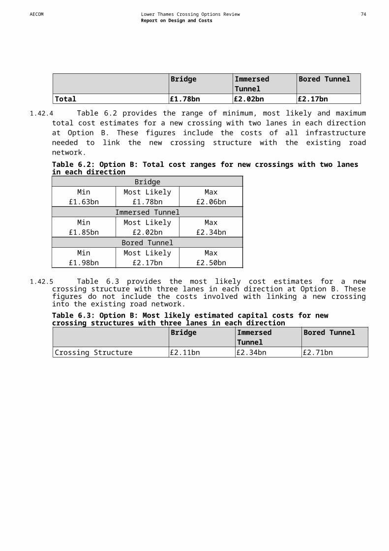
AECOM Lower Thames Crossing Options Review 76Report on Design and Costs
1.63 Costs
1.63.1 Capital costs were estimated from the dimensions of the conceptual designs using typical cost rates for delivery of comparable infrastructure. Outturn costs were estimated using the HA’s standard methodology. Allowances for the cost of risk and for inflation have been included in cost estimates.
1.63.2 Error: Reference source not found sets out the estimated most likely capital costs for new crossings providing an additional two lanes in each direction at Options A, B and C. Table 9.1 sets out the estimated capital costs for new crossing structures providing an additional three lanes in each direction at Options A, B and C (i.e. excluding the costs involved with linking new structures into the existing road network). The estimated most likely cost of the Cvariant link between the M2 and M20 is £1.77bn.Table 9.0: Most likely estimated capital costs for new crossing structures and link roads providing an additional two lanes in each direction
Bridge Immersed Tunnel Bored Tunnel
OPTION ACrossing Structure £0.91bn £1.18bn £1.15bnLink Roads £0.34bn £0.42bn £0.43bnTotal £1.25bn £1.60bn £1.57bn
OPTION BCrossing Structure £1.68bn £1.83bn £1.72bnLink Roads £0.10bn £0.19bn £0.45bnTotal £1.78bn £2.02bn £2.17bn
OPTION CCrossing Structure £1.82bn £1.83bn £1.93bnLink Roads £1.42bn £1.26bn £1.22bnTotal £3.24bn £3.09bn £3.15bn
Table 9.1: Most likely estimated capital costs for new crossing structures providing an additional three lanes in each direction
Bridge Immersed Tunnel Bored TunnelOPTION A £1.20bn £1.51bn £1.81bnOPTION B £2.11bn £2.34bn £2.71bnOPTION C £2.29bn £2.35bn £3.04bn
1.64 Type of Structure
1.64.1 We have developed conceptual designs for bridge, bored tunnel and immersed tunnel main crossing structures. Particular factors that will need to be considered, in addition to the relative costs, are that:
- The restriction of river navigation during construction of an immersed tunnel could have a significant impact on shipping.
- The location of bridge piers can restrict access to wharfs and hence constrain commercial activity, which would be of particular relevance for new crossings at location options a and b.
- Operational constraints can reduce flexibility for the movement of dangerous goods.
- Accident risks tend to be higher in tunnels.
- Bridges are susceptible to disruption from high winds, although we have allowed for provision of wind shielding in estimating costs.
- There would be impacts on the mudflats through digging a trench for an immersed tunnel and from the piers for a bridge.

AECOM Lower Thames Crossing Options Review 77Report on Design and Costs
- Options b and c in particular, may result in significant realignment of electricity lines.
1.65 Option A
1.65.1 Option A is located near to the existing Dartford-Thurrock Crossing. A new crossing at Option A would provide the fourth structure over or under the River Thames at this location. Option A is the most constrained location in terms of constructing a new crossing. Option A would impact on Green Belt Land within Thurrock north of the A1306 as the M25 passes through land designated as Green Belt at this location.
1.65.2 In terms of traffic operation, a bridge would be preferable due to additional flexibility of having four lanes operating together rather than split between two tunnel bores. This is because a bridge at location Option A has been assumed to operate with all four lanes running in the same direction. An obstruction in one lane would therefore still leave three running lanes open (a 25% capacity reduction). By contrast, an obstruction in one of the lanes in a new two lane tunnel would only leave one running lane open in the tunnel (a 50% capacity reduction), causing more disruption to traffic.
1.65.3 The estimated cost of a bridge crossing is lower than that for an immersed or bored tunnel irrespective of whether a four or six lane crossing is assumed.
1.66 Option B
1.66.1 A new River Thames crossing at Option B would run from the northern tip of the Swanscombe Peninsula in Kent to developed land between the urban area of Grays and the Port of Tilbury in Essex.
1.66.2 A bridge crossing would be twice as long as that required for Option A due to the increased 70m air draught needed for a bridge and the greater river width at this point, in part also reflecting the navigation requirements for access to Port of Tilbury Docks. The increased river width would also increase the length of tunnel required, but not to the same extent as for a bridge, with the result that the differential in cost between bridge and tunnel structures is lower at Option B than Option A.
1.66.3 It has been assumed that access to a bridge would be provided by a viaduct. On the northern bank of the River Thames the assumed illustrative route would be along the southwest edge of Grays and its potential impacts would require careful consideration. The assumed illustrative route for a new crossing at Option B would also enter land designated as Green Belt at its connection with the A1089.
1.66.4 The southern route to a new crossing at Option B is assumed to approximately follow the HS1 rail line. This is considered to reduce impacts on development potential. However, detailed design works would be needed to fully mitigate impacts.
1.66.5 The southern connection to the A2 has been assumed to be at the existing Ebbsfleet junction. Consideration of the traffic pressures along the A2, combined with those that may be generated from the nearby development sites would require careful consideration at later design stages if Option B was taken forwards.
1.66.6 Detailed design would be constrained by the requirements of existing infrastructure (the HS1 rail line, utilities, etc).
AECOM Lower Thames Crossing Options Review 78Report on Design and Costs
1.66.7 The estimated cost of providing a new crossing at Option B is higher than at Option A, reflecting the increased extents of the crossing needed.
1.66.8 The range in cost estimates between structures for crossing providing two lanes in each direction is relatively small and lies within the margin of error in the estimating process. The cost estimates for a bridge structure, and for the total cost of a bridge crossing, are lower than those for tunnel options. Overall costs per km for link roads are lower at Option B than at Option A because they are less complex and involve fewer structures.
1.66.9 As with Option A, the estimated cost of a bridge structure with three lanes in each direction is again less than the corresponding estimates for tunnel structures. The most expensive six lane crossing structure is again the bored tunnel.
1.67 Option C
1.67.1 The River Thames is wider at Option C than at Options A and B. This adds to the length of the crossing structures that would be needed generally. However, this factor is mitigated by Option C being in a less developed area, which would reduce construction complexity.
1.67.2 The navigation clearance needed for a bridge crossing at Option C is 70m, the same as for Option B. The main span would be longer than for Option B, however the overall length of a bridge at Option C would be less than a bridge at Option B as there are few other rail and road crossings that would extend a bridge structure beyond the length needed to return to ground level from the maximum crossing height.
1.67.3 On the south bank of the River Thames, the assumed illustrative route for a new crossing passes through the western margins of the Thames Estuary and Marshes Ramsar and SSSI designated site. All the structure options are assumed to impact on this site. The assumed illustrative route for a new crossing at Option C would pass through land designated as Green Belt throughout its length from the A2/M2 in Gravesham through Thurrock before connecting with the M25 in the London Borough of Havering.
1.67.4 Away from the crossing site, the southern connection of the assumed illustrative route would require a complex interchange with the A2/M2 near to the existing Junction 1 of the M2. The conceptual layout presented in this report requires extensive land take in an area of Ancient Woodland and recreational facilities. Additionally, the HS1 rail line constrains the site as it runs close to the A2/M2. No departures from road standards have been identified as being necessary at this stage, but further, more detailed, studies would be required to provide a clearer position on this issue. Constructing this junction has been shown to be feasible, but the additional complexity compared with the southern connections for Options A and B is marked and there are consequent risks that a more detailed design would show more risks to delivery.
1.67.5 On the Essex side of the River Thames there would be a 14km link to the M25, with an intermediate junction link to the A13. There are feasibility risks involved with the conceptual design for the junction with the A13, including proving that the Orsett Cock junction would have sufficient capacity and the likely need to avoid Scheduled Monuments north and south of the A13.
1.67.6 As in the case of Option B, the range in cost estimates between structures for crossings providing two lanes in each direction is relatively small and lies within the margin of error in the estimating process. The estimated cost for a bridge crossing structure is again lower than for a tunnel, but with a much reduced margin. However, as the estimated cost of the link roads associated with a bridge are higher than those for tunnel options the total cost estimate for a bridge crossing is higher than for both a bored tunnel crossing and an immersed tunnel crossing, which has the lowest cost estimate.
AECOM Lower Thames Crossing Options Review 79Report on Design and Costs
1.67.7 As for Options A and B the estimated cost of a bridge structure providing three lanes in each direction is lower at Option C than the comparable estimates for tunnel structures. The cost estimate for a bored tunnel is again higher than for an immersed tunnel.
1.68 Option Cvariant
1.68.1 The engineering complexities and risks involved with the road infrastructure needed for the Option Cvariant (an enhancement to the A229 between the M2 and M20) are comparable, in many ways, to those involved with new crossing options at locations A, B & C. Most significantly, a road tunnel has been assumed to provide a free-flow connection for traffic between the M2 (west) and the A229 (south). The conceptual tunnel design is at the limit of normal standards in terms of permissible gradients. The assumed enhancement to the A229 would not affect land designated as Green Belt.
1.68.2 The feasibility of providing the viaducts assumed at the northern and southern connections is more assured than the tunnel but more detailed analysis would need to be carried out to prove constructability.
1.68.3 The conceptual design for the widened A229 demonstrates its overall feasibility for this study but the complexity of the local access provision is significant and some risks of feasibility are, thus, apparent.
1.68.4 In overall terms, the deliverability of the Option Cvariant is questionable due to the engineering challenges of the tunnel as well as the relatively higher overall estimated costs (£1.77bn) of providing the infrastructure, which (for comparison purposes only) exceeds the total cost estimates for a new crossing at Option A.

Appendices

AECOM Lower Thames Crossing Options Review 81Report on Design and Costs
Appendix A – Figures (see separate volume)
AECOM Lower Thames Crossing Options Review 82Report on Design and Costs
Appendix B – Detailed Cost Information
Table B1.1: Cost estimates for Option ABridge Imm'sed Tunnel Bored Tunnel
Min ML Max Min ML Max Min ML Max
£2.379 £2.952 £3.778 £2.381 £2.953 £3.780 £2.444 £3.051 £3.915
£8.245 £9.700 £12.125 £9.095 £10.700 £13.375 £9.241 £10.873 £13.591
£77.338 £97.744 £126.342 £77.016 £97.110 £125.400 £78.259 £98.691 £127.432
£105.934 £129.558 £164.793 £160.917 £195.849 £248.554 £164.456 £200.162 £254.031
£31.590 £38.684 £48.869 £47.661 £58.462 £73.911 £44.345 £54.462 £68.841
£259.811 £323.371 £420.776 £326.845 £416.213 £481.577 £310.993 £396.360 £509.098
£64.096 £79.776 £90.907 £70.056 £89.211 £168.199 £71.773 £91.475 £117.493
£46.300 £57.300 £72.600 £60.700 £76.100 £97.300 £59.300 £74.400 £95.000
£9.601 £11.807 £14.924 £10.643 £13.137 £16.611 £10.875 £13.431 £16.980
£8.166 £9.606 £12.007 £10.798 £12.704 £15.879 £10.400 £12.237 £15.296
£15.800 £19.600 £24.900 £20.800 £26.000 £33.200 £20.204 £25.308 £32.414
Sub-total £629.260 £780.098 £992.020 Sub-total £796.911 £998.439 £1,277.786 Sub-total £782.291 £980.450 £1,254.091
Range Narrowing £78.624 £0.000 -£94.870 Range Narrowing £104.590 £0.000 -£125.398 Range Narrowing £102.667 £0.000 -£122.730Inflation £360.882 £391.280 £457.611 Inflation £466.114 £507.909 £598.893 Inflation £453.705 £498.208 £579.912
Programme Risk £52.629 £73.958 £93.895 Programme Risk £67.696 £94.508 £119.570 Programme Risk £66.423 £92.818 £117.457
Grand Total £1,121.395 £1,245.336 £1,448.656 Grand Total £1,435.312 £1,600.856 £1,870.850 Grand Total £1,405.086 £1,571.477 £1,828.729
Development Phase (ii) Preliminary Design
& Procedures
Project Overheads & Method Related
Contractor Fee
Statutory Undertakers
£ millions
Options Phase
Development Phase(i) Land
Non Recoverable VAT
Options Phase
Development Phase(i) Land
Development Phase (ii) Preliminary Design
& Procedures
Project Overheads & Method Related
Roadworks
Main Crossing Structure
Other Structures
Contractor Fee
Statutory Undertakers
Construction Overheads
Construction Overheads
Non Recoverable VAT
Options Phase
Development Phase(i) Land
Development Phase (ii) Preliminary Design
& Procedures
Project Overheads & Method Related
Roadworks
Main Crossing Structure
Other Structures
Contractor Fee
Statutory Undertakers
Construction Overheads
Non Recoverable VAT
Roadworks
Main Crossing Structure
Other Structures
AECOM Lower Thames Crossing Options Review 83Report on Design and Costs
Table B1.2: Cost estimates for Option BBridge Imm'sed Tunnel Bored Tunnel
Min ML Max Min ML Max Min ML Max
£2.274 £2.777 £3.533 £2.398 £2.985 £3.825 £2.496 £3.145 £4.052
£10.200 £12.000 £15.000 £13.345 £15.700 £19.625 £14.483 £17.036 £21.296
£77.887 £98.558 £127.385 £87.299 £109.346 £140.242 £94.285 £118.108 £151.503
£122.933 £149.093 £188.905 £169.647 £203.467 £255.850 £198.402 £237.953 £299.215
£21.168 £25.915 £32.716 £32.230 £40.319 £51.333 £26.670 £33.022 £41.834
£445.283 £549.340 £695.177 £458.209 £567.925 £718.283 £420.498 £521.641 £659.831
£5.653 £6.974 £8.826 £13.267 £16.444 £20.797 £85.263 £105.772 £133.792
£59.600 £73.200 £92.600 £67.400 £82.900 £104.700 £73.200 £89.900 £113.600
£10.404 £12.674 £15.963 £10.771 £13.240 £16.728 £11.104 £13.642 £17.222
£10.770 £12.670 £15.838 £11.801 £13.882 £17.353 £12.810 £15.069 £18.838
£131.900 £161.900 £204.900 £148.900 £183.000 £231.200 £161.578 £198.417 £250.451
Sub-total £898.073 £1,105.101 £1,400.843 Sub-total £1,015.268 £1,249.207 £1,579.937 Sub-total £1,100.790 £1,353.703 £1,711.635
Range Narrowing £111.607 £0.000 -£136.360 Range Narrowing £125.187 £0.000 -£151.206 Range Narrowing £136.097 £0.000 -£163.306Inflation £543.950 £570.333 £665.771 Inflation £620.884 £649.180 £759.478 Inflation £647.639 £692.039 £790.901
Programme Risk £75.079 £104.597 £132.187 Programme Risk £84.787 £118.112 £149.261 Programme Risk £91.884 £127.964 £161.712
Grand Total £1,628.709 £1,780.030 £2,062.441 Grand Total £1,846.126 £2,016.498 £2,337.469 Grand Total £1,976.409 £2,173.706 £2,500.941
Construction Overheads
Non Recoverable VAT
Options Phase
Development Phase(i) Land
Development Phase (ii) Preliminary Design
& Procedures
Project Overheads & Method Related
Roadworks
Main Crossing Structure
Other Structures
Contractor Fee
Statutory Undertakers
£ millions
Contractor Fee
Statutory Undertakers
Options Phase
Development Phase(i) Land
Development Phase (ii) Preliminary Design
& Procedures
Project Overheads & Method Related
Construction Overheads
Non Recoverable VAT
Options Phase
Development Phase(i) Land
Development Phase (ii) Preliminary Design
& Procedures
Project Overheads & Method Related
Roadworks
Main Crossing Structure
Other Structures
Contractor Fee
Statutory Undertakers
Construction Overheads
Non Recoverable VAT
Roadworks
Main Crossing Structure
Other Structures
AECOM Lower Thames Crossing Options Review 84Report on Design and Costs
Table B1.3: Cost estimates for Option CBridge Imm'sed Tunnel Bored Tunnel
Min ML Max Min ML Max Min ML Max
£2.300 £2.833 £3.620 £2.360 £2.911 £3.717 £2.376 £2.912 £3.707
£32.550 £43.400 £56.420 £39.900 £53.200 £69.160 £40.583 £54.121 £70.385
£204.234 £257.780 £332.884 £195.879 £248.107 £321.041 £200.509 £251.980 £325.036
£248.709 £294.020 £359.148 £251.852 £313.402 £412.630 £277.571 £344.027 £451.648
£89.887 £106.220 £129.097 £90.806 £111.513 £137.321 £85.341 £104.715 £128.911
£454.473 £545.846 £668.978 £410.354 £527.757 £746.967 £421.238 £541.220 £771.793
£267.423 £321.189 £393.643 £192.961 £248.168 £351.247 £183.613 £235.912 £336.416
£106.100 £126.800 £155.200 £94.700 £120.200 £164.900 £96.800 £122.700 £169.000
£29.158 £35.458 £44.669 £29.886 £36.477 £45.978 £30.106 £36.665 £46.200
£19.738 £22.446 £26.825 £16.914 £20.636 £28.574 £17.554 £21.435 £29.800
£231.100 £276.000 £337.900 £206.700 £261.900 £358.700 £211.384 £267.434 £367.375
Sub-total £1,685.673 £2,031.992 £2,508.383 Sub-total £1,532.312 £1,944.272 £2,640.234 Sub-total £1,567.075 £1,983.120 £2,700.269
Range Narrowing £184.605 £0.000 -£216.423 Range Narrowing £227.084 £0.000 -£303.745 Range Narrowing £236.418 £0.000 -£309.460Inflation £953.476 £1,014.926 £1,136.963 Inflation £888.914 £964.477 £1,128.700 Inflation £926.915 £983.983 £1,195.581
Programme Risk £138.927 £192.354 £246.481 Programme Risk £130.116 £183.347 £234.538 Programme Risk £133.061 £187.467 £238.364
Grand Total £2,962.681 £3,239.272 £3,675.405 Grand Total £2,778.426 £3,092.096 £3,699.727 Grand Total £2,863.468 £3,154.570 £3,824.754
Development Phase (ii) Preliminary Design &
Procedures
Project Overheads & Method Related
Contractor Fee
Statutory Undertakers
Construction Overheads
Roadworks
Main Crossing Structure
Other Structures
Non Recoverable VAT
Options Phase
Development Phase(i) Land
Development Phase (ii) Preliminary Design &
Procedures
Project Overheads & Method Related
Roadworks
Main Crossing Structure
Other Structures
Contractor Fee
Statutory Undertakers
Options Phase
Development Phase(i) Land
Construction Overheads
Non Recoverable VAT
Options Phase
Development Phase(i) Land
Development Phase (ii) Preliminary Design &
Procedures
Project Overheads & Method Related
Roadworks
Main Crossing Structure
Other Structures
Contractor Fee
Statutory Undertakers
Construction Overheads
Non Recoverable VAT

AECOM Lower Thames Crossing Options Review 85Report on Design and Costs
Table B1.4: Cost estimate for Option CvariantMin ML Max
£2.477 £3.041 £3.858
£8.700 £11.600 £15.080
£127.939 £160.149 £206.139
£182.522 £226.021 £294.225
£64.063 £78.571 £96.630
£306.375 £387.495 £549.558
£39.765 £50.293 £71.327
£59.300 £74.400 £101.200
£18.619 £22.562 £28.365
£11.281 £13.728 £18.797
£64.900 £81.200 £110.300
Sub-total £885.940 £1,109.059 £1,495.479
Range narrowing £126.498 £0.000 -£165.893Inflation £510.627 £553.719 £661.150
Programme Risk £74.527 £105.124 £133.724
Grand Total £1,597.592 £1,767.903 £2,124.460
Construction Overheads
Non Recoverable VAT
Roadworks
Main Crossing Structure
Other Structures
Contractor Fee
Statutory Undertakers
£ millions
Options Phase
Development Phase(i) Land
Development Phase
(ii) Preliminary Project
Overheads & Method Related

AECOM Lower Thames Crossing Options Review 86Report on Design and Costs
Appendix C – Constraints TablesTable C1.1: Option A ContraintsRoute option Resource / Receptor Potential impact Avoidance options Mitigation options Supporting commentsAIR QUALITYA An AQMA has been declared
for the A282 J1a-J1b by Dartford Borough Council.
If traffic flows increase on the A282 or M25 due to the crossing, this is likely to worsen air quality in an area that has been declared an AQMA. If the AQMA is still in existence in the opening year, this could be a serious issue if properties are located near these roads. The assumed link passes through commercial and residential areas.
Locate the new link at least 120m from road centre to nearest properties
Pollutant concentrations were calculated using the DMRB screening method for 2025 with a traffic flow of 65,000 AADT on the new link. Local background concentrations were used and an adjustment factor based on a model monitoring comparison included. Calculations were made using emission rates for 2025 and as a sensitivity test 2010 as there is much uncertainty in the emission rates. The distance over which the annual mean NO2 limit value would be exceeded is 20m larger with the 2010 emission rates. The distance with the 2025 emission rates is quoted in this table. Please note that the traffic flow used is indicative. No indication is available of how traffic flows would change on other roads.
BIODIVERSITYA Mudflat habitat Habitat loss, physical barrier
to movement of wintering birds (severance), disturbance to wintering birds (particularly during construction activities).
Bored tunnel instead of a bridge.
Monitoring of habitat, particularly of bird activity, well in advance of any building works to establish species and movement patterns. Use this information to establish the overall design of the bridge and timing of works. Design features may include a low noise surface and a height, which allows movement of birds / reduction of disturbance by traffic. Post monitoring will be essential to gauge impacts and provide useful information for future bridge schemes. Mudflat habitat cannot essentially be replaced, however there is a possibility of providing similar habitat enhancement in the vicinity under the guide of e.g. the Wildlife Trusts / RSPB (biodiversity off-setting). Take into account any unique plant or invertebrate species which may be present.
If a tunnel was constructed instead of a bridge, the main impacts would be from disturbance to birds during construction and any loss of habitat around the entrances and exits of the tunnel.
A Reed bed habitat Habitat loss, disturbance to nesting birds.
Avoid these habitat features by re-routing.
Ensure that a minimum amount of habitat is lost to the scheme and remaining habitat is enhanced where possible.
A Recommended Marine Conservation Zone (MCZ)
Habitat loss, physical barrier to movement of wintering birds (severance), disturbance to wintering birds (particularly during construction activities).
Bored tunnel instead of a bridge.
Monitoring of habitat, particularly of bird activity, well in advance of any building works to establish species and movement patterns. Use this information to establish the overall design of the bridge and timing of works. Design features may include a low noise surface and a height, which allows movement of birds / reduction of disturbance by traffic. Post monitoring will be essential to gauge impacts and provide useful information for future bridge schemes. Mudflat habitat cannot essentially be replaced, however there is a possibility of providing similar habitat enhancement in the vicinity under the guide of the Wildlife Trusts.
MCZs are designated to protect nationally important marine wildlife, habitats, geology and geomorphology. The Marine Conservation Zone Project selects MCZs in English inshore waters and offshore waters next to England, Wales and Northern Ireland. Sites are selected to protect not just the rare and threatened, but the range of marine wildlife. The Thames Estuary was one of 127 sites around the coast recommended to Government as possible Marine Conservation Zones. The Government has proposed to designated 31 sites as Marine Conservation Zones, this does not include the Thames Estuary. Further designations will follow in tranche 2.
A West Thurrock Lagoon and Marshes SSSI
Habitat loss, disturbance to nesting birds.
Bored tunnel instead of a bridge.
Monitoring of habitat, particularly of bird activity, well in advance of any building works to establish species and movement patterns. Use this information to establish the overall design of the bridge and timing of works. Design features may include a low noise surface and a height which allows movement of birds / reduction of disturbance by traffic. Post monitoring will be essential to gauge impacts and provide useful information for future bridge schemes.
If a tunnel was constructed instead of a bridge, the main impacts would be from disturbance to birds during construction and any loss of habitat around the entrances and exits of the tunnel.
A Ancient Woodland (Watts Wood)
No anticipated constraint therefore this site is not considered further.

AECOM Lower Thames Crossing Options Review 87Report on Design and Costs
Route option Resource / Receptor Potential impact Avoidance options Mitigation options Supporting commentsHERITAGE OF HISTORIC RESOURCESA Site 81: Second World War
spigot mortar site, now destroyed, north of London Road, West Thurrock.
Physical impact on the site of the former Spigot Mortar.
If possible avoid but if unavoidable minimal impact.
Watching brief during construction Demolition of this monument is likely to have removed most evidence.Could be a moderately significant constraint.
A Site 271: Ring ditch visible on aerial photographs.
Physical impact on the site of the cropmarks.
Likely to be unavoidable but avoid if possible.
Possible need for evaluation work which may lead to full excavation of resource
Cropmark sites can be spread over a larger area than the initial cropmark depicts. Impact on the resource maybe reduced by mitigation measures and extent of remains.Not a significant constraint.
LANDSCAPE AND TOWNSCAPEA Visual receptors Visual impact, relating to
changes in the character of views and visual amenity of visual receptors, as a result of the introduction of traffic and/or highway related structures in views. Visual receptors include residential receptors in north-east Dartford, Purfleet and West Thurrock. Other receptors include recreational users of public rights of way and the River Thames.
Visual impacts can be avoided through use of existing landscape features to provide a screen between the route and settlements, or by locating road in cutting/false cutting.
NOISEA Dartford Residential
PropertiesIf road traffic flows were to increase on the A282 and M25, noise levels would subsequently increase. Road traffic flows would have to increase by 25% for a corresponding increase in noise level of 1 dB(A).
Noise barriers and low noise road surfaces options can be implemented to control adverse changes in noise levels
WATER ENVIRONMENTA River Thames Morphological changes to
River Thames due to road crossing
A bored tunnel will not result in permanent adverse morphological effects on River Thames.
An immersed tunnel can potentially have substantial effects on the hydromorphology of River Thames, if not completely submerged underneath the river bed. Should a bridge be required, it is acknowledged that an open span crossing may not be a technically feasible option for the River Thames crossing. Nevertheless, the shorter the crossing the more likelihood for an open span structure to be installed. Bridge piers should be located as far as practicable from the river bed. Any structure crossing River Thames should be designed so that it maintains the riparian habitat and minimises any adverse effects.
Where watercourse crossings cannot be avoided bored tunnels are preferred to bridges, as they do not affect the morphology of the watercourse. Immersed tunnels may not only have an adverse effect during construction but also a substantial adverse effect during operation due to effects on sediment deposition and alteration of flows. Good practice should be followed and appropriate tunnel/bridge design should ensure that any potential adverse effects can be effectively mitigated. Crossings should be perpendicular to the river to ensure that the crossing is as short as possible.
A Network of small drains, ditches and ponds north and south of River Thames
Morphological changes to minor watercourses due to diversions and/or road crossings
Watercourse crossings and diversions of surface water features should be avoided, where possible, to reduce the risk of morphological effects
Where watercourse crossings cannot be avoided, open span bridges are preferred to culverts as these help to maintain the riparian habitat. Should culverts be required, these will be designed to encourage the formation of a natural bed and to allow flows through the structure and fish movements.Watercourse diversions should be undertaken following good practice to minimise any potential adverse effect.
As per comments for the River Thames.

AECOM Lower Thames Crossing Options Review 88Report on Design and Costs
Route option Resource / Receptor Potential impact Avoidance options Mitigation options Supporting commentsA Flood Zone 2/3 and
associated defences:*- Fluvial and tidal flood plain to the north and south of the River Thames. – Defences along the north and south banks of the River Thames.
a) Direct risk of flooding to highway or construction site from watercourse or tidal source (Thames).b) Loss of flood storage volume (including loss through impedance of flood flows) due to the development or due to spoil storage during construction, leading to increased flooding elsewhere.c) Increasing flood risk by affecting flood defences or river flows during construction or operation.*Note that area at risk may be greater than the current Flood Zone 2/3 extent when climate change projections are taken into account.
a) Locate all structures and construction sites outside area at risk of flooding.b) Locate all structures and spoil storage outside area at risk of flooding. Avoid changes to topography.c) Avoid any impact on flood defence structures.
a) Raise level of highway above flood level. Develop flood emergency plans for construction sites.b) Provide compensatory storage elsewhere. Maintain free passage of flood flows. Agree management of spoil storage with EA or provide temporary compensatory storage.c) Ensure any proposed change to flood defences, works which could potentially affect defences, and works which could affect river flows are designed appropriately, including allowing for continuity during construction.
Locations were identified from the following datasets:- Flood Zone 2 and 3 from EA data; and- Formal flood defence locations from EA data.Detailed assessment of the fluvial and tidal flood risk to the route and the performance of flood defences will be required in order to determine the potential effects on flood risk and any necessary mitigation. This assessment should incorporate analysis of EA modelled flood data, possible hydraulic modelling to improve on EA data, liaison with EA and Local Authority. All assessments must including an appropriate allowance for the projected effects of climate change. All potential flood risk sources should be considered and appropriate mitigation incorporated into the highway design and construction methodology. The assessment of flood risk to the route and the potential affect of the route on flood risk, should be considered at all stages of design development, as any necessary mitigation may be fundamental to the design.
A Main Rivers, Ordinary Watercourses, land drains and ditches:
- Drainage networks within the land to the north and south of the River Thames.
a) Risk of afflux flooding (upstream) due to crossing of watercourse or land drain.
b) Risk of increased runoff to watercourse or land drain causing increase in flood risk from watercourse.
c) Risk of temporary increased runoff or silt/debris ladened runoff during construction causing increase in flood risk from watercourse or land drain.
d) Risk of flooding resulting from change in watercourse/drain flow regime due to morphological changes for development
a) Avoid all watercourse/land drain crossings.
b) Ensure no surface water discharges to watercourses/drains.
c) Locate site compounds and construction works to ensure no potential for runoff to watercourses/drains.
d) Avoid changes to watercourses/drains or works nearby.
a) Provide appropriately designed tunnel/bridge/culvert structures to ensure no affect on watercourse flows.
b) Appropriate surface water drainage and attenuation to be provided.
c) Appropriate temporary drainage and site management to be provided.
d) Ensure any proposed changes to watercourses/drains are designed appropriately to avoid adverse affects.
Locations were identified from the following datasets:- Main rivers from EA data; and- Ordinary watercourses from OS mapping.
Due to the nature of small watercourses and land drainage, it is difficult to ascertain from OS mapping exactly where all are located. In order to establish the existence of land drains and assess the associated flood risk, further site investigations and consultation with local landowners and the Land Drainage Authority should be undertaken at a later stage.
Detailed assessment of the flood risk associated with all watercourses on or nearby the route will be required in order to determine the potential effects on flood risk and any necessary mitigation. This assessment should incorporate analysis of EA modelled flood data, possible hydraulic modelling to improve on EA data, liaison with EA, Local Authority and Land Drainage Authority.
All assessments must including an appropriate allowance for the projected effects of climate change.
All potential flood risk sources should be considered in any FRA and EIA for any future scheme and appropriate mitigation incorporated into the highway design and construction methodology.
The assessment of flood risk to the route and the potential affect of the route on flood risk, should be considered at all stages of design development, as any necessary mitigation may be fundamental to the design.

AECOM Lower Thames Crossing Options Review 89Report on Design and Costs
Table C1.2: Option B ConstraintsRoute option Resource / Receptor Potential impact Avoidance options Mitigation options Supporting commentsAIR QUALITYB1 An AQMA has been declared
for the A226 leading to the assumed crossing by Dartford Borough Council (BC).
If traffic flows increase on the A226 due to the crossing, this is likely to worsen air quality in an area that has been declared an AQMA. If the AQMA is still in existence in the opening year , this could be a serious issue if properties are located near this road. The assumed link passes through some moderately populated areas, this is the most populated of the route options.
Locate the new link at least 50m from road centre to nearest properties
Pollutant concentrations were calculated using the DMRB screening method for 2025 with a traffic flow of 65,000 AADT on the new link. Local background concentrations were used and an adjustment factor based on a model monitoring comparison included. Calculations were made using emission rates for 2025 and as a sensitivity test 2010 as there is much uncertainty in the emission rates. The distance over which the annual mean NO2 limit value would be exceeded is 20m larger with the 2010 emission rates. The distance with the 2025 emission rates is quoted in this table. Please note that the traffic flow used is indicative. No indication is available of how traffic flows would change on other roads.
BIODIVERSITYB1 Coastal and Floodplain
Grazing Marsh habitatHabitat loss and severance. Avoid these habitat features
by re-routing.Ensure that a minimum amount of habitat is lost to the scheme and remaining habitat is enhanced where possible. Similar habitat creation or improvement in a different location, under the guide of, e.g. Wildlife Trusts (biodiversity off-setting). Protected species such as water vole may be present. This habitat will require specialist surveys which will inform exact mitigation options.
B1 Mudflat habitat Habitat loss, physical barrier to movement of wintering birds (severance), disturbance to wintering birds (particularly during construction activities).
Bored tunnel instead of a bridge.
Monitoring of habitat, particularly of bird activity, well in advance of any building works to establish species and movement patterns. Use this information to establish the overall design of the bridge and timing of works. Design features may include a low noise surface and a height which allows movement of birds / reduction of disturbance by traffic. Post monitoring will be essential to gauge impacts and provide useful information for future bridge schemes. Mudflat habitat cannot essentially be replaced, however there is a possibility of providing similar habitat enhancement in the vicinity under the guide of e.g. the Wildlife Trusts / RSPB (biodiversity off-setting). Take into account any unique plant or invertebrate species which may be present.
If a tunnel was constructed instead of a bridge, the main impacts would be from disturbance to birds during construction and any loss of habitat around the entrances and exits of the tunnel.
B1 Reed bed habitat Habitat loss, disturbance to nesting birds.
Avoid these habitat features by re-routing.
Ensure that a minimum amount of habitat is lost to the scheme and remaining habitat is enhanced where possible.
B1 Recommended Marine Conservation Zone (MCZ)
Habitat loss, physical barrier to movement of wintering birds (severance), disturbance to wintering birds (particularly during construction activities).
Bored tunnel instead of a bridge.
Monitoring of habitat, particularly of bird activity, well in advance of any building works to establish species and movement patterns. Use this information to establish the overall design of the bridge and timing of works. Design features may include a low noise surface and a height which allows movement of birds / reduction of disturbance by traffic. Post monitoring will be essential to gauge impacts and provide useful information for future bridge schemes. Mudflat habitat cannot essentially be replaced, however there is a possibility of providing similar habitat enhancement in the vicinity under the guide of the Wildlife Trusts.
MCZs are designated to protect nationally important marine wildlife, habitats, geology and geomorphology. The Marine Conservation Zone Project selects MCZs in English inshore waters and offshore waters next to England, Wales and Northern Ireland. Sites are selected to protect not just the rare and threatened, but the range of marine wildlife. The Thames Estuary was one of 127 sites around the coast recommended to Government as possible Marine Conservation Zones. The Government has proposed to designated 31 sites as Marine Conservation Zones, this does not include the Thames Estuary. Further designations will follow in tranche 2.
B1 West Thurrock and Marshes SSSI
Indirect effects related to sediment and pollution during construction.West Thurrock Lagoon and
Ensure sedimentation and pollution during construction is limited.
The minimisation of sediments and pollutants into the Thames will minimise the effect on this receptor.

AECOM Lower Thames Crossing Options Review 90Report on Design and Costs
Route option Resource / Receptor Potential impact Avoidance options Mitigation options Supporting commentsMarshes is one of the most important sites for wintering waders and wildfowl on the Inner Thames Estuary. The combination of extensive intertidal mudflats together with a large and secure high tide roost, attracts waders in nationally important numbers, with significant populations of other bird species. The adjacent Stone Ness saltmarsh is noted for the size and character of its high marsh plant community.
B1 Darenth Wood SSSI Indirect effects of increased noise and decreased air quality leading to nitrogen and particulate deposition due to increased traffic along the A1089
Vegetation buffer used as screening
B1 Hangman's Wood and Dene Holes SSSI No anticipated constraint therefore this site is not considered further.B1 Ancient Woodland (Chadwell
Wood and Parkhill Wood)Indirect effects of increased noise and decreased air quality leading to nitrogen and particulate deposition due to increased traffic along the A1089.
Vegetation buffer used as screening
B1 Ancient Woodland (The Thrift)
Potential habitat loss depending on location of working corridor; Indirect effects of increased noise and decreased air quality leading to nitrogen and particulate deposition due to increased traffic along the A2.
Arboricultural surveys; Vegetation buffer used as screening
B1 Ancient Woodland (Beacon Hill) No anticipated constraint therefore this site is not considered further.HERITAGE OF HISTORIC RESOURCESB1 Site 164: Remains of
wooden planks and squared stakes visible in the salt marsh cliff edge at Botany saltmarshes. May be the remains of a 19th century or later platform.
Physical impact on the site should it survive.
Avoid if possible Excavation and recording of resource if impacted. Former wooden planks and squared stakes in the edge of the salt marshes mean that they may have become damaged and possibly destroyed. This will require further investigation to establish. Could be a moderately significant constraint if remains found to be still well preserved.
B1 Site 168 & 485: Roman coin, bronze cup and Samian sherd found in Mounts Wood in 1868.
Possible physical impact. None required None required The find spots themselves are of little importance as the artefacts have been removed. However, associated material could be located in area.Not a significant constraint.
B1 Site 176: Find spot of Roman material including human remains and pottery
Limited impact. Located during construction works. Remains removed.
Excavation and recording of resource if impacted. None although site could indicate further remains of a similar nature nearby.Not a significant constraint.
B1 Site 283: Bronze Age pottery findspot and lower
Limited impact. Located during construction works. Remains removed.
Unlikely to be required The site has already been excavated for new construction and therefore nothing remains to be impacted. However, the site
AECOM Lower Thames Crossing Options Review 91Report on Design and Costs
Route option Resource / Receptor Potential impact Avoidance options Mitigation options Supporting commentsPalaeolithic tools could indicate further similar remains are located nearby.
Not a significant constraint.B1 Site 324: Post or stake
holes, Bexley Hospital Phase II.
None. Located during construction works. Remains removed.
Unlikely to be required The site has already been evaluated for the site of a new building and therefore nothing remains to be impacted.Not a significant constraint.
B1 Site 325: 37 Palaeo. Handaxes, 1 core and 6 pieces of debitage.
Possible physical impact. None required None required The find spot itself is of little importance as the artefact has been removed. However, associated material could be located in area.Not a significant constraint.
B1 Site 287, 334 & 339: Cast Iron Bridge, Swanscombe Heritage Park & Craylands Gorge.
Possible physical impact on the bridge depending on design. Setting will be impacted.
Avoid if possible. Setting impact is unavoidable
Full recording of resource through historic building survey. The bridge is likely to be removed. If physical impacts are avoided its setting will be affected.Moderately significant constraint.
B1 Site 336 and 335: Pipeline with supports, Swanscombe Heritage Park and Craylands Gorge.
Possible physical impact on the site depending on design. Setting will be impacted.
Avoid if possible. Setting impact is unavoidable
Photographic recording of resource. The pipe with supports is likely to be removed if impacted. If it is avoided its setting will be impacted.Not a significant constraint.
B1 Site 337: Brick Pier, Swanscombe Heritage Park and Craylands Gorge.
Possible physical impact on the site depending on design. Setting will be impacted.
Avoid if possible. Setting impact is unavoidable
Photographic recording of resource. The brick pier is likely to be removed if impacted. If it is avoided its setting will be impacted.Not a significant constraint.
B1 Site 340: Cast Iron Pipe, Swanscombe Heritage Centre and Craylands Gorge.
Possible physical impact on the site depending on design. Setting will be impacted.
Avoid if possible. Setting impact is unavoidable
Photographic recording of resource. The pipe is likely to be removed if impacted. If it is avoided its setting will be impacted.Not a significant constraint.
B1 Site 286, 288, 338 & 341: Concrete Tramway Tunnel, Swanscombe Heritage Centre and Craylands Gorge.
Possible physical impact. Likely to be unavoidable but not necessary to avoid.
Full recording of resource through historic building survey. If impacted the site will require recording. Not a significant constraint.
B1 Site 349: Swanscombe Heritage Park and Craylands Gorge. Includes lower Palaeolithic hominid remains and Swanscombe Skull Site SSSI / NNR. Additional Palaeolithic finds have been recording in surrounding mineral extraction areas.
Physical impact on the site and its setting.
Avoid if possible. Setting impact is unavoidable
Recording of resource required. Landscape screening to mitigate setting impacts.
Any impact should be avoided where possible The setting of the park could be impacted. This Palaeolithic findspot is extremely rare and any further finds will be of national importance. Could be a major significant constraint.
B1 Site 909: Route of Roman Road. Preservation status uncertain as in close proximity to quarry
Physical impact on the site should it survive.
Avoid if possible Excavation and recording of resource if impacted. Former mineral extraction may have affected preservation status of Roman road. This will require further investigation to establish. Could be a major significant constraint.
B1 Site 496: New Craylands Lane Pit. A quantity of human and animal remains and 2nd to 3rd century Roman pottery was found in New Craylands pit, Swanscombe.
Possible physical impact. None required None required The find spots themselves are of little importance as the artefacts have been removed. However, associated material could be located in area. Not a significant constraint.
LANDSCAPE AND TOWNSCAPEB1 Visual receptors Visual impact, relating to
changes in the character of views and visual amenity of visual receptors, as a result of the introduction of traffic
Visual impacts can be avoided through use of existing landscape features to provide a screen between the route and settlements, or

AECOM Lower Thames Crossing Options Review 92Report on Design and Costs
Route option Resource / Receptor Potential impact Avoidance options Mitigation options Supporting commentsand/or highway related structures in views. Visual receptors include residential receptors in Bean, Swanscombe and the southern edge of Grays. Other receptors include recreational users of public rights of way, recreational areas such as Swanscombe Marshes and the River Thames.
by locating road in cutting/false cutting.
B1 Green Wedge between Swanscombe and Greenhithe
Potential loss of a wooded river corridor area with some playing fields to the side. This area is likely to be of amenity value at a local level.
Avoid this area.
NOISEB1 Bean The new section of road
assumed adjacent to Bean may result in an increase in noise levels at residential receptors. However, these receptors will already experience significant levels of road traffic noise from road traffic on the A2 so the change in noise may not be significant.
Locate new sections of road at least 130 metres from sensitive receptors.
Noise barriers and low noise road surfaces options can be implemented to control adverse changes in noise levels
Noise calculations have been carried out using the Basic Noise Level method from CRTN using AAWT flows of 60,000, traffic speeds of 70mph and 10% HGV. Distances for avoidance options have been assessed using the LAeq,16h trigger level of 68 dB(A) from The Noise insulation Regulations.
B1 Swanscombe/Greenhithe The new section of road assumed between Greenhithe and Swanscombe may result in significant increase in road traffic noise at nearby sensitive receptors, as there are no existing significant sources of road traffic.
Locate new sections of road at least 130 metres from sensitive receptors.
Noise barriers and low noise road surfaces options can be implemented to control adverse changes in noise levels. Sensitive receptors may qualify for compensation due to noise from new sections of road as stated in the Land Compensation Act
Noise calculations have been carried out using the Basic Noise Level method from CRTN using AAWT flows of 60,000, traffic speeds of 70mph and 10% HGV. Distances for avoidance options have been assessed using the LAeq,16h trigger level of 68 dB(A) from The Noise insulation Regulations.
B1 Thameside Infant School The new section of road is assumed to pass nearby to Thameside Infant School may result in significant increase in road traffic noise at nearby sensitive receptors as there are no existing significant sources of road traffic.
Locate new sections of road at least 130 metres from sensitive receptors.
Noise barriers and low noise road surfaces options can be implemented to control adverse changes in noise levels. Sensitive receptors may qualify for compensation due to noise from new sections of road as stated in the Land Compensation Act
Noise calculations have been carried out using the Basic Noise Level method from CRTN using AAWT flows of 60,000, traffic speeds of 70mph and 10% HGV. Distances for avoidance options have been assessed using the LAeq,16h trigger level of 68 dB(A) from The Noise insulation Regulations.
WATER ENVIRONMENTB1 River Thames Morphological changes to
River Thames due to road crossing
A bored tunnel will not result in permanent adverse morphological effects on River Thames.
An immersed tunnel can potentially have substantial effects on the hydromorphology of River Thames, if not completely submerged underneath the river bed. Should a bridge be required, it is acknowledged that an open span crossing may not be a technically feasible option for the River Thames crossing. Nevertheless, the shorter the crossing the more likelihood for an open span structure to be installed. Bridge piers should be located as far as practicable from the river bed. Any structure crossing River Thames should be designed so that it maintains the riparian habitat and minimises any adverse effects.
Where watercourse crossings cannot be avoided bored tunnels are preferred to bridges, as they do not affect the morphology of the watercourse. Immersed tunnels may not only have an adverse effect during construction but also a substantial adverse effect during operation due to effects on sediment deposition and alteration of flows. Good practice should be followed and appropriate tunnel/bridge design should ensure that any potential adverse effects can be effectively mitigated. Crossings should be perpendicular to the river to ensure that the crossing is as short as possible.
AECOM Lower Thames Crossing Options Review 93Report on Design and Costs
Route option Resource / Receptor Potential impact Avoidance options Mitigation options Supporting commentsB1 Network of small drains,
ditches and ponds north and south of River Thames
Morphological changes to minor watercourses due diversions and/or road crossings
Watercourse crossings and diversions of surface water features should be avoided, where possible, to reduce the risk of morphological effects
Where watercourse crossings cannot be avoided, open span bridges are preferred to culverts as these help to maintain the riparian habitat. Should culverts be required, these will be designed to encourage the formation of a natural bed and to allow flows through the structure and fish movements.Watercourse diversions should be undertaken following good practice to minimise any potential adverse effect.
As per comments for the River Thames.
B1 Groundwater abstraction for public supply or food/drink production.
Pollution from road runoff and/or spillage entering the underlying groundwater and migrating to the abstraction at unacceptable concentrations.
Diversion of route option. Diversion of route option.Closed (non-sustainable) drainage systems in and adjacent to SPZ1. Emergency planning for spills.
Source Protection Zones are assigned for major groundwater abstractions for public supply or other sensitive uses such as brewing and food production. There are nearly 2000 SPZs across England and Wales. They are not currently Statutory, but the Environment Agency use them to assist in implementation of certain legislation. The EA also apply them in the initial assessment of development proposals and in development control (Planning). In the inner zone of each SPZ (SPZ1) the EA will object in principle to, or refuse to permit, some activities. Other than inside SPZ1, the EA will support the use ofsustainable drainage systems for new discharges to ground of surface run-off from roads.
B1 Flood Zone 2/3 and associated defences*:
- Fluvial and tidal flood plain to the north and south of the River Thames. - Defences along the north and south banks of the River Thames.- Defences inland on Main River to north side of River Thames.
a) Direct risk of flooding to highway or construction site from watercourse or tidal source (Thames).
b) Loss of flood storage volume (including loss through impedance of flood flows) due to the development or due to spoil storage during construction, leading to increased flooding elsewhere.
c) Increasing flood risk by affecting flood defences or river flows during construction or operation.
*Note that area at risk may be greater than the current Flood Zone 2/3 extent when climate change projections are taken into account.
a) Locate all structures and construction sites outside area at risk of flooding.
b) Locate all structures and spoil storage outside area at risk of flooding. Avoid changes to topography.
c) Avoid any impact on flood defence structures or river flows.
a) Raise level of highway above flood level. Develop flood emergency plans for construction sites.
b) Provide compensatory storage elsewhere. Maintain free passage of flood flows. Agree management of spoil storage with EA or provide temporary compensatory storage.
c) Ensure any proposed change to flood defences, works which could potentially affect defences, and works which could affect river flows are designed appropriately, including allowing for continuity during construction.
Locations were identified from the following datasets:- Flood Zone 2 and 3 from EA data; and- Formal flood defence locations from EA data.
Detailed assessment of the fluvial and tidal flood risk to the route and the performance of flood defences will be required in order to determine the potential effects on flood risk and any necessary mitigation. This assessment should incorporate analysis of EA modelled flood data, possible hydraulic modelling to improve on EA data, liaison with EA and Local Authority.
All assessments must including an appropriate allowance for the projected effects of climate change.
All potential flood risk sources should be considered in any FRA and EIA and appropriate mitigation incorporated into the highway design and construction methodology.
The assessment of flood risk to the route and the potential affect of the route on flood risk, should be considered at all stages of design development, as any necessary mitigation may be fundamental to the design.
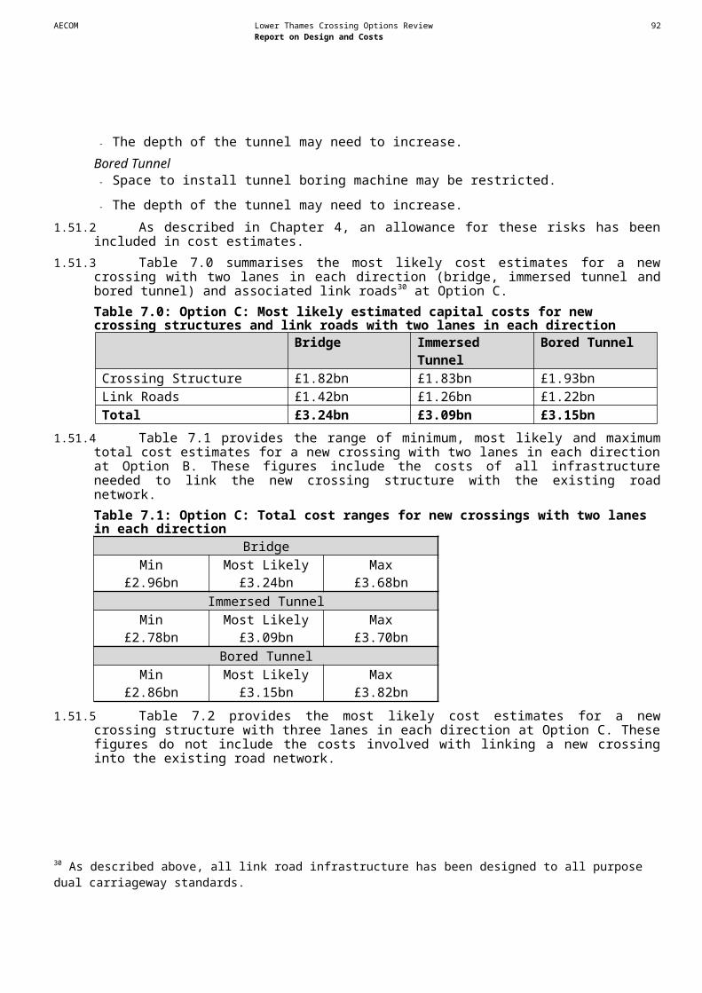
AECOM Lower Thames Crossing Options Review 94Report on Design and Costs
Route option Resource / Receptor Potential impact Avoidance options Mitigation options Supporting commentsB1 Main Rivers, Ordinary
Watercourses, land drains and ditches:
- Drainage networks within the land to the north and south of the River Thames.- Various drainage features around the southern end of the route.
a) Risk of afflux flooding (upstream) due to crossing of watercourse or land drain.
b) Risk of increased runoff to watercourse or land drain causing increase in flood risk from watercourse.
c) Risk of temporary increased runoff or silt/debris ladened runoff during construction causing increase in flood risk from watercourse or land drain.
d) Risk of flooding resulting from change in watercourse/drain flow regime due to morphological changes for development
a) Avoid all watercourse/land drain crossings.
b) Ensure no surface water discharges to watercourses/drains.
c) Locate site compounds and construction works to ensure no potential for runoff to watercourses/drains.
d) Avoid changes to watercourses/drains or works nearby.
a) Provide appropriately designed tunnel/bridge/culvert structures to ensure no affect on watercourse flows.
b) Appropriate surface water drainage and attenuation to be provided.
c) Appropriate temporary drainage and site management to be provided.
d) Ensure any proposed changes to watercourses/drains are designed appropriately to avoid adverse affects.
Locations were identified from the following datasets:- Main rivers from EA data; and- Ordinary watercourses from OS mapping.
Due to the nature of small watercourses and land drainage, it is difficult to ascertain from OS mapping exactly where all are located. In order to establish the existence of land drains and assess the associated flood risk, further site investigations and consultation with local landowners and the Land Drainage Authority should be undertaken at a later stage.
Detailed assessment of the flood risk associated with all watercourses on or nearby the route will be required in order to determine the potential effects on flood risk and any necessary mitigation. This assessment should incorporate analysis of EA modelled flood data, possible hydraulic modelling to improve on EA data, liaison with EA, Local Authority and Land Drainage Authority.
All assessments must including an appropriate allowance for the projected effects of climate change.
All potential flood risk sources should be considered in any FRA and EIA for any future scheme and appropriate mitigation incorporated into the highway design and construction methodology.
The assessment of flood risk to the route and the potential affect of the route on flood risk, should be considered at all stages of design development, as any necessary mitigation may be fundamental to the design.
Additional information for Sub Option B2 (the constraints identified for B1 are also constraints for B2 unless otherwise stated)Route option Resource / Receptor Potential impact Avoidance options Mitigation options Supporting commentsAIR QUALITYB2 No additional constraints
have been identified.
BIODIVERSITYB2 No additional constraints
have been identified. The constraints identified in respect of B1 apply.
HERITAGE OF HISTORIC RESOURCESB2 Darenth Wood Scheduled
Monument - this is a medieval (circa 1200 to 1250 AD) enclosed forest with banks surviving to 0.5m high and 12m wide.
Potential damage to the Scheduled Monument and impacts on setting.
Avoid physical impacts if possible. Setting impact is unavoidable
Further evaluation and assessment. This site is upstanding and any route nearby would have to consider visual impacts as well as any possible below ground remains.
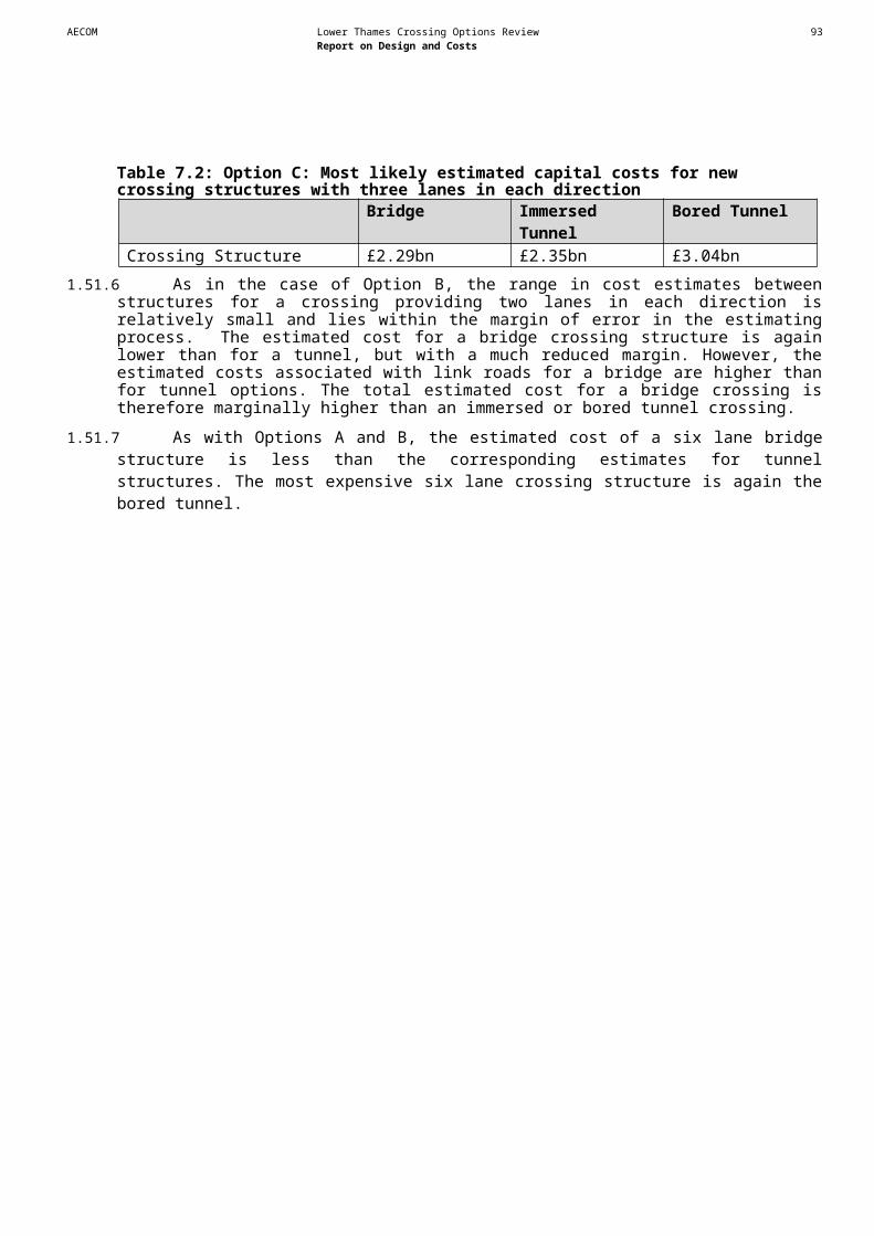
AECOM Lower Thames Crossing Options Review 95Report on Design and Costs
Route option Resource / Receptor Potential impact Avoidance options Mitigation options Supporting commentsLANDSCAPE AND TOWNSCAPEB2 Green Wedge between
Swanscombe and Greenhithe
Loss of this area would be avoided but there could be a visual impact on a wooded river corridor area with some playing fields to the side. This area is likely to be of amenity value at a local level.
Visual impacts can be avoided through use of existing landscape features to provide a screen between the route and this area.
NOISEB2 Existing housing North of the Eastern Quarry
Site the alignment passes close to existing housing, which would likely be adversely affected by an increase in noise level due to the new road.
Existing property within approximately 130m of the alignment may receive noise levels at and above 68 dB(A), which is the national threshold for granting noise insulation.
Mitigation is likely to be required, which in the first instance could comprise shifting the alignment to the east; and, noise barrier mitigation on the carriageway edge.
Sub Option B2 tries to avoid most of the Eastern Quarry Site by sharing the same corridor as the Bluewater Shopping Centre access (B255).
WATER ENVIRONMENTB2 Source Protection Zones No affect on groundwater north
of the Thames. On the south side, Sub Option B2 would avoid one central SPZ area (SPZ1) at the southern limit of the original Option B, but will now impinge on the edge of a different SPZ1 area, as it swings further west. No significant change in groundwater constraints for this option.
Additional information for Sub Option B3(the constraints identified for B1 and B2 are also constraints for B3 unless otherwise stated)Route option Resource / Receptor Potential impact Avoidance options Mitigation options Supporting commentsAIR QUALITYB3 No additional constraints
have been identified although the Thrift would not be affected under this sub-option.
BIODIVERSITYB3 No additional constraints
have been identified.
AECOM Lower Thames Crossing Options Review 96Report on Design and Costs
Route option Resource / Receptor Potential impact Avoidance options Mitigation options Supporting commentsHERITAGE OF HISTORIC RESOURCESB3 For B3, the following sites
which were within 50m of the assumed illustrative route for sub-Option B1 will no longer be constraints: Site 168 & 485Site 176Site 283Site 324Site 325Site 287, 334 & 339Site 336 and 335Site 337Site 340Site 286, 288, 338 & 341Site 349Site 496
B3 Site 911: Vagniacis Scheduled Monument – this is a Roman settlement and is fairly widespread. An associated Temple is to the south-east of the main settlement and is also Scheduled. This site is likely to have extensive associated remains, both domestic and agricultural in the surrounding vicinity. In addition to the Roman remains, a smaller Neolithic Scheduled Monument lies to the north.
Potential damage to the Scheduled Monument and impacts on setting.
Avoid physical impacts if possible. Setting impact is unavoidable
Further evaluation and assessment. Any alignment near to these monuments may well involve significant amounts of field evaluation. Major significant constraint.
B3 Site 912: Two Neolithic sites near Ebbsfleet. Both are Scheduled Monuments.
Physical impact on sites Avoid if possible Excavation and recording of resource if impacted. Scheduled Monuments. Major significant constraint and should be avoided wherever possible.
B3 Site 913: Palaeolithic Scheduled Monument - this is a lower Palaeolithic site associated with Bakers Hole, one of the more famous Palaeolithic sites in Britain.
Potential damage to the Scheduled Monument and impacts on setting.
Avoid physical impacts if possible. Setting impact is unavoidable
Further evaluation and assessment. Also Bakers Hole Geological SSSI.Major significant constraint.
LANDSCAPE AND TOWNSCAPEB3 Green Wedge between
Swanscombe and Greenhithe
The green wedge would no longer be a constraint.
AECOM Lower Thames Crossing Options Review 97Report on Design and Costs
Route option Resource / Receptor Potential impact Avoidance options Mitigation options Supporting commentsNOISEB3 Existing housing There is a buffer between the
existing developed residential area on the western side of the alignment, which if greater than 130m would avoid particularly adverse impacts exceeding the national threshold noise level at which noise insulation is granted.
Adverse impacts to these properties could be further ameliorated by noise barrier on the carriageway edge. To the east of the alignment is the existing HS1 and farther eastward a lesser number of residential properties.There would appear to be an advantage in terms of noise impact by moving the alignment closer to the HS1 and farther from the more densely development areas to the west.
Sub Option B2 connects further east at the B259/Ebbsfleet Station junction. However, it is quite a distance from the Bean junction assumed for Option B in the brief. It follows the HS1 transport corridor and affects the industrial estate at the end of Manor Way near Swanscombe.
There is much greater opportunity for distance separation from the road to existing and future sensitive receivers, which will help to reduce the magnitude of impact.
WATER ENVIRONMENTB3 Source Protection Zones No effect to the north of the
Thames. On the south side, Sub Option B3 would avoid the SPZ1 at the southern limit of Option B, but will now go through a similar sized SPZ1 at the southern end of the new alignment. No significant change in groundwater constraints for this option.
AECOM Lower Thames Crossing Options Review 98Report on Design and Costs
Table C1.3: Option C ConstraintsRoute option Resource / Receptor Potential impact Avoidance options Mitigation options Supporting commentsAIR QUALITYC An AQMA has been declared
for the A2 leading to the assumed crossing by Gravesham Borough Council.
If traffic flows increase on the A2 due to the crossing, this is likely to worsen air quality in areas that have been declared AQMAs. If the AQMA is still in existence in the opening year, this could be a serious issue if properties are located near these roads. The assumed links pass through largely rural areas but some small areas are lightly to moderately populated.
Locate the new crossing link at least 40m from road centre to nearest properties.
Pollutant concentrations were calculated using the DMRB screening method for 2025 with a traffic flow of 65,000 AADT on the new link. Local background concentrations were used and an adjustment factor based on a model monitoring comparison included. Calculations were made using emission rates for 2025 and as a sensitivity test 2010 as there is much uncertainty in the emission rates. The distance over which the annual mean NO2 limit value would be exceeded is 20m larger with the 2010 emission rates. The distance with the 2025 emission rates is quoted in this table. Please note that the traffic flow used is indicative. No indication is available of how traffic flows would change on other roads.
C An AQMA has been declared for Havering by London Borough of Havering.
If traffic flows increase on roads in Havering due to the crossing, this is likely to worsen air quality in areas that have been declared AQMAs. If the AQMA is still in existence in the opening year, this could be a serious issue if properties are located near these roads. The assumed links pass through largely rural areas but some small areas are lightly to moderately populated.
Locate the new crossing link at least 40m from road centre to nearest properties in the LB Havering. The distance would need to be greater for properties near the M25 and the new link.
Pollutant concentrations were calculated using the DMRB screening method for 2025 with a traffic flow of 65,000 AADT on the new link. Local background concentrations were used and an adjustment factor based on a model monitoring comparison included. Calculations were made using emission rates for 2025 and as a sensitivity test 2010 as there is much uncertainty in the emission rates. The distance over which the annual mean NO2 limit value would be exceeded is 20m larger with the 2010 emission rates. The distance with the 2025 emission rates is quoted in this table. Please note that the traffic flow used is indicative. No indication is available of how traffic flows would change on other roads.
C An AQMA has been declared for Maidstone by Maidstone Borough Council near the M2 M20 link.
If traffic flows increase on roads in Maidstone due to the crossing, this is likely to worsen air quality in areas that have been declared an AQMA. If the AQMA is still in existence in the opening year, this could be a serious issue if properties are located near these roads. The assumed links pass through largely rural areas but some small areas are lightly to moderately populated.
Locate the new link at least 45m from road centre to properties.
Pollutant concentrations were calculated using the DMRB screening method for 2025 with a traffic flow of 65,000 AADT on the new link. Local background concentrations were used and an adjustment factor based on a model monitoring comparison included. Calculations were made using emission rates for 2025 and as a sensitivity test 2010 as there is much uncertainty in the emission rates. The distance over which the annual mean NO2 limit value would be exceeded is 20m larger with the 2010 emission rates. The distance with the 2025 emission rates is quoted in this table. Please note that the traffic flow used is indicative. No indication is available of how traffic flows would change on other roads.
C Vegetation sensitive to nitrogen deposition in South Thames Estuary and Marshes SSSI, Thames Estuary and Marshes Ramsar site and Shorne and Ashenbank Woods SSSI
Nitrogen oxides (NOx) emissions from road traffic resulting in increased nitrogen deposition, potentially affecting plant health, productivity and species composition.
Avoid these habitat features by re-routing. Adverse effects are unlikely beyond 200m.
Existing and future nitrogen deposition rates likely to affect designated features which are sensitive to air pollution would need to be predicted and compared to critical loads. The potential for significant impacts to occur is dependent on baseline nitrogen deposition rates in relation to critical loads for the vegetation types specific to each site.

AECOM Lower Thames Crossing Options Review 99Report on Design and Costs
Route option Resource / Receptor Potential impact Avoidance options Mitigation options Supporting commentsBIODIVERSITYC Coastal and Floodplain
Grazing Marsh habitatHabitat loss and severance. Avoid these habitat features
by re-routing.Ensure that a minimum amount of habitat is lost to the scheme and remaining habitat is enhanced where possible. Similar habitat creation or improvement in a different location, under the guide of, e.g. Wildlife Trusts (biodiversity off-setting). Protected species such as water vole may be present. This habitat will require specialist surveys which will inform exact mitigation options.
C Mudflat habitat Habitat loss, physical barrier to movement of wintering birds (severance), disturbance to wintering birds (particularly during construction activities).
Bored tunnel instead of a bridge.
Monitoring of habitat, particularly of bird activity, well in advance of any building works to establish species and movement patterns. Use this information to establish the overall design of the bridge and timing of works. Design features may include a low noise surface and a height which allows movement of birds / reduction of disturbance by traffic. Post monitoring will be essential to gauge impacts and provide useful information for future bridge schemes. Mudflat habitat cannot essentially be replaced, however there is a possibility of providing similar habitat enhancement in the vicinity under the guide of e.g. the Wildlife Trusts / RSPB (biodiversity off-setting). Take into account any unique plant or invertebrate species which may be present.
If a tunnel was constructed instead of a bridge, the main impacts would be from disturbance to birds during construction and any loss of habitat around the entrances and exits of the tunnel.
C Reed bed habitat Habitat loss, disturbance to nesting birds.
Avoid these habitat features by re-routing.
Ensure that a minimum amount of habitat is lost to the scheme and remaining habitat is enhanced where possible.
C Ramsar site (Thames Estuary and Marshes)
Habitat loss, severance and disturbance of a site designated for its international importance of a variety of birds, invertebrates and wetland plants.
Bored tunnel instead of a bridge.
Monitoring of habitat, particularly of bird activity, well in advance of any building works to establish species and movement patterns. Use this information to establish the overall design of the bridge and timing of works. Design features may include a low noise surface and a height which allows movement of birds / reduction of disturbance by traffic. Post monitoring will be essential to gauge impacts and provide useful information for future bridge schemes. Mudflat habitat cannot essentially be replaced, however there is a possibility of providing similar habitat enhancement in the vicinity under guide of e.g. Wildlife Trusts / RSPB (biodiversity off-setting).
C SSSI (South Thames Estuary and Marshes)
Habitat loss and severance of a site designated for its importance as an extensive mosaic of grazing marsh, saltmarsh, mudflat and shingle, characteristic of the North Kent marshes. The SSSI supports outstanding numbers of internationally important waterfowl, and rare and scarce plants and invertebrates. Disturbance, particularly during construction activities.
Bored tunnel instead of a bridge.
Monitoring of habitat, particularly of bird activity, well in advance of any building works to establish species and movement patterns. Use this information to establish the overall design of the bridge and timing of works. Design features may include a low noise surface and a height which allows movement of birds / reduction of disturbance by traffic. Post monitoring will be essential to gauge impacts and provide useful information for future bridge schemes. Mudflat habitat cannot essentially be replaced, however there is a possibility of providing similar habitat enhancement in the vicinity under the guide of e.g. the Wildlife Trusts / RSPB (biodiversity off-setting).
If a tunnel was constructed instead of a bridge, the main impacts would be from disturbance to birds during construction and any loss of habitat around the entrances and exits of the tunnel.
C SSSI (Mucking Flats and Marshes)
Although the crossing is not directly upon this receptor, increased noise (disturbance) and the barrier effect of a bridge for birds (severance) are potential adverse impacts on this SSSI which is located to the east of Option C.
Bored tunnel instead of a bridge.
Biodiversity offsetting may be necessary if impacts would found to be adverse.

AECOM Lower Thames Crossing Options Review 100Report on Design and Costs
Route option Resource / Receptor Potential impact Avoidance options Mitigation options Supporting commentsC SSSI (Shorne and
Ashenbank Woods)Habitat loss of a SSSI which is designated for its complex of ancient and plantation woodland and includes a variety of stand types associated with Tertiary gravels, clays and sands. The site supports an important and diverse invertebrate fauna, especially its Coleoptera, Hemiptera and Odonata. Severance of habitat by the road and increase in noise/disturbance during construction and operation.
Avoid these habitat features by re-routing.
Timing of works to avoid the bird breeding season for the majority of works. Full ecological surveys prior to any works, and mitigation measures implemented based upon findings. European protected species such as dormouse, great crested newt and bats may be present in such a habitat. These all require unique mitigation measures and will require licences. Biodiversity off-setting by enhancing areas of similar habitat in other parts of Kent under the guidance of e.g. Wildlife Trust. With Ancient Woodland, there will be a residual impact, as this habitat cannot be re-created immediately in another location since it takes many decades to establish.
C Great Crabbles Wood SSSI Indirect effects of decreased air quality leading to nitrogen and particulate deposition due to increased traffic along the A289.This site is representative of woods on North West Kent Tertiary sediments; these comprise a succession of strata over Upper Chalk ranging from Blackheath gravels to Woolwich loams and Thanet sands, which give rise to a range of soil types. The succession of soils is reflected in the species composition of the tree canopy, shrub layer and ground flora. Mixed coppice under Oak standards and contains a number of scarce plants, including lady orchid Orchis purpurea and man orchid Aceras anthropophorum.
Vegetation buffer screen
C Cobham Woods SSSI Potential habitat loss depending on location of working corridor and Indirect effects of increased noise and decreased air quality leading to nitrogen and particulate deposition due to increased traffic along the A289. This woodland and old parkland is representative of woods in North Kent which occur in part on acidic Thanet Sands and in part on chalk soils. One nationally rare plant species occurs in the arable
Ensure working corridor does not encroach on Cobham Woods SSSI
Arboricultural surveys; Vegetation buffer used as screening
AECOM Lower Thames Crossing Options Review 101Report on Design and Costs
Route option Resource / Receptor Potential impact Avoidance options Mitigation options Supporting commentsland close to the wood. An outstanding assemblage of plants is present at this site which is also of importance for its breeding birds.
C Recommended Marine Conservation Zone (MCZ)
Habitat loss, physical barrier to movement of wintering birds (severance), disturbance to wintering birds (particularly during construction activities).
Bored tunnel instead of a bridge.
Monitoring of habitat, particularly of bird activity, well in advance of any building works to establish species and movement patterns. Use this information to establish the overall design of the bridge and timing of works. Design features may include a low noise surface and a height which allows movement of birds / reduction of disturbance by traffic. Post monitoring will be essential to gauge impacts and provide useful information for future bridge schemes. Mudflat habitat cannot essentially be replaced, however there is a possibility of providing similar habitat enhancement in the vicinity under the guide of the Wildlife Trusts.
MCZs are designated to protect nationally important marine wildlife, habitats, geology and geomorphology. The Marine Conservation Zone Project selects MCZs in English inshore waters and offshore waters next to England, Wales and Northern Ireland. Sites are selected to protect not just the rare and threatened, but the range of marine wildlife. The Thames Estuary was one of 127 sites around the coast recommended to Government as possible Marine Conservation Zones. The Government has proposed to designated 31 sites as Marine Conservation Zones, this does not include the Thames Estuary. Further designations will follow in tranche 2.
C Thames Estuary and Marshes Special Protection Zone (SPA)
Although the crossing is not directly upon this receptor, increased noise (disturbance) and the barrier effect of a bridge for birds (severance) are potential adverse impacts on the SPA to the east of this Option.
Bored tunnel instead of a bridge.
A Habitats Regulations Assessment (HRA) would be necessary early on to screen the potential impacts of a bridge structure being located close to the SPA. This information could be used in the design of a bridge as mentioned previously. Biodiversity offsetting may be necessary if impacts would found to be adverse.
C Ancient Woodland habitat (Claylane Woods)
Indirect effects of increased noise and decreased air quality leading to nitrogen and particulate deposition due to increased traffic.
Vegetation buffer used as screening
Cvariant (M2-M20 link) North Downs Woodlands Special Area of Conservation (SAC)
Indirect effects of increased noise and decreased air quality leading to nitrogen and particulate deposition during construction and post-construction increase in traffic. Potential habitat loss depending on working corridor.Designated for mature Asperulo-Fagetum beech forests and also yew Yew Taxus baccata woods on steep slopes and Semi-natural dry grasslands and scrubland facies: on calcareous substrates (Festuco-Brometalia)
Vegetation buffer used as screening
Cvariant (M2-M20 link) Ancient Woodland habitat (Bridge Woods)
Loss of Woodland Edge Avoid these habitat features by re-routing.
Ensure that a minimum amount of habitat is lost to the scheme and remaining habitat is enhanced where possible. Similar habitat creation or improvement in a different location, under the guide of, e.g. Wildlife Trusts (biodiversity off-setting). Protected species such as bats may be present. This habitat may require specialist surveys which will inform exact mitigation options.

AECOM Lower Thames Crossing Options Review 102Report on Design and Costs
Route option Resource / Receptor Potential impact Avoidance options Mitigation options Supporting commentsCvariant (M2-M20 link) SSSI (Wouldham to Detling
Escarpment)Possible habitat loss or disturbance of Units 8 and 11 of the SSSI (which are currently in favourable condition). The SSSI includes representative examples of woodland, scrub and unimproved grassland habitats on chalk, which support a number of rare (including Buxus sempervirens, a rare small tree, native here at one of a handful of sites in the south-east) and scarce (including lady orchid Orchis purpurea and stinking hellebore Helleborus foetidus) species of plants and invertebrates.
Avoid these habitat features by re-routing.
Ensure that a minimum amount of habitat is lost to the scheme and remaining habitat is enhanced where possible. Similar habitat creation or improvement in a different location, under the guide of, e.g. Wildlife Trusts (biodiversity off-setting). Protected species such as bats may be present. This habitat may require specialist surveys which will inform exact mitigation options.
Cvariant (M2-M20 link) Ancient Woodland within 2km of the illustrative alignment
Indirect effects of increased noise and decreased air quality leading to nitrogen and particulate deposition due to increased traffic.
Vegetation buffer used as screening
Cvariant (M2-M20 link) Peters Pit SAC No anticipated constraint therefore this site is not considered further.HERITAGE OF HISTORIC RESOURCESC Site 8: High House,
Chadwell. Eighteenth century timber framed house. Grade II listed building.
Possible physical and visual impacts
Avoid physical impacts. Setting impact is unavoidable
English Heritage building recording and possible excavation if impacted.
This building is also on the Building at Risk register (35220). Listed building consent would be required for demolition of the building.Major significant constraint.
C Site 59: Orsett Roman finds, located north of Seaborough Hall, Orsett Heath.
Possible physical impacts Avoid where possible Further evaluation and assessment. Survival and extent uncertain.Moderately significant constraint.
C Site 120 and Site 73: North Ockendon Hall dating to the sixteenth century and destroyed during the Second World War. A moated house with garden wall.
Possible physical impacts Avoid if possible Further evaluation and assessment. Survival and extent uncertain. The hall was destroyed in WWII but buried remains could still exist.Not a significant constraint.
C Site 131, Site 874 and Site 858: Church of St Mary Magdalene, North Ockendon. Grade II* listed.
Possible physical and visual impacts
Avoid English Heritage building recording and possible excavation if impacted.
Major significant constraint.
C Site 132: Filborough farmhouse, Grade II listed.
Possible physical and visual impacts
Avoid English Heritage building recording and possible excavation if impacted.
Major significant constraint.
C Site 139: Granary at Little Filborough Farm. Grade II listed building.
Possible physical and visual impacts
Avoid English Heritage building recording and possible excavation if impacted.
Major significant constraint.
C Site 156: Peat banks eroding into the River Thames, Eastcourt Marshes.
Possible physical impact. Avoid if possible Further evaluation and assessment. Few details known about site. Survival uncertain.Could be a moderately significant constraint if archaeological remains are located within deposits.
C Site 179: Find spot of a brass of Constantinus.
Possible physical impact. None required None required The find spot itself is of little importance as the artefact has been removed. However, associated material could be located in area.Not a significant constraint.
AECOM Lower Thames Crossing Options Review 103Report on Design and Costs
Route option Resource / Receptor Potential impact Avoidance options Mitigation options Supporting commentsC Site 185: Romano-British
occupation area.Physical impact on the site. Avoid if possible. Excavation and recording of resource if impacted. The scale and extent of the site is unknown and therefore
difficult to measure impact at this stage.Could be a moderately significant constraint.
C Site 190: Ring Ditch, possibly a round barrow, surviving as a cropmark.
Possible physical impacts Avoid if possible Further evaluation and assessment. Survival and extent uncertain.Moderately significant constraint.
Cvariant (M2-M20 link) Site 202 & 580: Romano-British burials found 1919-20 found in a sand pit. .
Possible physical impact. Avoid if possible. Evaluation of area for presence of additional burials. Although the burials have been removed additional remains could be located in the area.Moderately significant constraint.
Cvariant (M2-M20 link) Site 210: Lower White Horse Stone or Kentish Standard Stone, Aylesford.
Possible physical impact. Avoid if possible. Further evaluation and assessment. Survival and extent uncertain.Could be a moderately significant constraint.
Cvariant (M2-M20 link) Site 220: A defensive structure known as Delce Tower has been recorded at Burham.
Possible physical impact. Site likely to have been destroyed by road construction.
None required None required Not a significant constraint.
C Site 232: Possible remains of park pale found under made ground at Cobham Park.
Possible physical impact. Site likely to have been destroyed by during construction.
None required None required Possible further remains could survive.Not a significant constraint.
C Site 233: Possible denehole (shaft sunk into chalk) in Cobham Park.
Possible physical impact. Site likely to have been destroyed by road construction.
None required None required Not a significant constraint.
Cvariant (M2-M20 link) Site 236: Bluebell Quarries, Boxley, Maidstone.
Possible physical impact. Site likely to have been destroyed by road construction.
None required None required Possible further remains could survive.Not a significant constraint.
C Site 273: Salt workings. Possible physical impact. Avoid if possible. Further evaluation and assessment. Few details known about site. Survival uncertain.Could be a moderately significant constraint.
C Site 295: A possible barrow discovered during field survey work in 2002.
Possible physical impact. Avoid if possible. Further evaluation and assessment. Few details known about site. Survival uncertain.Moderately significant constraint.
C Site 299: Clay pits, probably of post-medieval date, discovered during field survey work in 2002.
Possible physical impact. Avoid if possible. Further evaluation and assessment. Survival and extent uncertain.Not a significant constraint.
C Site 303: Extensive clay extraction quarry, Shorne Wood Country Park.
Possible physical impact. None required None required Possible further remains could survive although unlikely.Not a significant constraint.
C Site 304: Post-medieval clay pits, Shorne Wood Country Park.
Possible physical impact. None required None required Possible further remains could survive although unlikely.Not a significant constraint.
C Site 305 and 306: Post-medieval marl pit, Shorne Wood Country Park.
Possible physical impact. None required None required Possible further remains could survive although unlikely.Not a significant constraint.
C Site 309: Evidence of old 'plashing' in woodland at road boundary, identified during field survey work in 2004.
Possible physical impact. None required None required Possible further remains could survive although unlikely.Not a significant constraint.
C Site 315: A small extraction pit, partially filled in, with apparent spoil on south side, identified during field survey work in 2004.
Possible physical impact. None required None required Possible further remains could survive although unlikely.Not a significant constraint.
C Site 318: A ditch running north - south with a high
Possible physical impact. Avoid if possible Further evaluation and assessment. Few details known about site. Survival uncertain.Could be a moderately significant constraint if archaeological

AECOM Lower Thames Crossing Options Review 104Report on Design and Costs
Route option Resource / Receptor Potential impact Avoidance options Mitigation options Supporting commentsridge on its western side cut by a modern access road to the west of Brewers Wood. Identified during field survey work in 2004.
remains are located within deposits.
C Site 322 and 894: Cobham Hall and Lady Darnley's Garden, Cobham Hall. Surveyed in 2003.
Possible physical and visual impacts
Avoid if possible Further evaluation and assessment. Survival and extent uncertain. A Registered Park.Major significant constraint.
Cvariant (M2-M20 link) Site 328: A Palaeolithic handaxe, Bluebell Hill, Aylesford.
Possible physical impact. None required None required The find spot itself is of little importance as the artefact has been removed. However, associated material could be located in area.Not a significant constraint.
C Site 360: Rochester Road Second World War road block, Chalk.
Physical impact on the site a road block.
If possible avoid but if unavoidable minimal impact.
Watching brief during construction Demolition of this monument is likely to have removed most evidence.Not a significant constraint.
Cvariant (M2-M20 link) Site 386: Iron Age / Roman ditch near Junction 6, M20.
Possible physical impact. Site likely to have been destroyed by road construction.
None required None required Possible further remains could survive.Not a significant constraint.
C Site 398: Roman copper alloy brooch.
Possible physical impact. None required None required The find spot itself is of little importance as the artefact has been removed. However, associated material could be located in area.Not a significant constraint.
C Site 399: Roman copper alloy brooch.
Possible physical impact. None required None required The find spot itself is of little importance as the artefact has been removed. However, associated material could be located in area.Not a significant constraint.
C Site 403: Roman copper alloy coin.
Possible physical impact. None required None required The find spot itself is of little importance as the artefact has been removed. However, associated material could be located in area.Not a significant constraint.
C Site 404: Roman copper alloy coin.
Possible physical impact. None required None required The find spot itself is of little importance as the artefact has been removed. However, associated material could be located in area.Not a significant constraint.
C Site 405: Roman copper alloy brooch.
Possible physical impact. None required None required The find spot itself is of little importance as the artefact has been removed. However, associated material could be located in area.Not a significant constraint.
C Site 411: Roman copper alloy coin.
Possible physical impact. None required None required The find spot itself is of little importance as the artefact has been removed. However, associated material could be located in area.Not a significant constraint.
C Site 412: Medieval copper alloy harness pendant.
Possible physical impact. None required None required The find spot itself is of little importance as the artefact has been removed. However, associated material could be located in area.Not a significant constraint.
C Site 414: Roman copper alloy plate brooch.
Possible physical impact. None required None required The find spot itself is of little importance as the artefact has been removed. However, associated material could be located in area.Not a significant constraint.
C Site 415: Roman copper alloy plate brooch.
Possible physical impact. None required None required The find spot itself is of little importance as the artefact has been removed. However, associated material could be located in area.Not a significant constraint.
C Site 416: Roman copper Possible physical impact. None required None required The find spot itself is of little importance as the artefact has
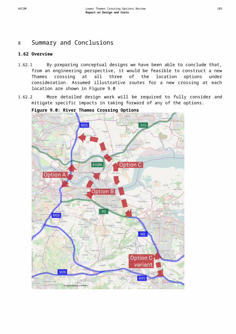
AECOM Lower Thames Crossing Options Review 105Report on Design and Costs
Route option Resource / Receptor Potential impact Avoidance options Mitigation options Supporting commentsalloy brooch. been removed. However, associated material could be located
in area.Not a significant constraint.
C Site 418: Copper alloy knife. Possible physical impact. None required None required The find spot itself is of little importance as the artefact has been removed. However, associated material could be located in area.Not a significant constraint.
C Site 419: Post-medieval copper alloy unidentified object.
Possible physical impact. None required None required The find spot itself is of little importance as the artefact has been removed. However, associated material could be located in area.Not a significant constraint.
C Site 423: Roman copper alloy coins.
Possible physical impact. None required None required The find spot itself is of little importance as the artefact has been removed. However, associated material could be located in area.Not a significant constraint.
C Site 425: Roman finds including a copper alloy brooch and a coins.
Possible physical impact. None required None required The find spot itself is of little importance as the artefact has been removed. However, associated material could be located in area.Not a significant constraint.
Cvariant (M2-M20 link) Site 431: Iron Age copper alloy coin.
Possible physical impact. None required None required The find spot itself is of little importance as the artefact has been removed. However, associated material could be located in area.Not a significant constraint.
C Site 446: Prehistoric flint and pottery, Shorne.
Possible physical impact. None required None required The find spot itself is of little importance as the artefact has been removed. However, associated material could be located in area.Not a significant constraint.
C Site 447: During field walking along the Shorne to Farningham pipeline route, Roman brick and pottery were collected from this area.
Possible physical impact. None required None required The find spots themselves are of little importance as the artefact has been removed. However, associated material could be located in area.Not a significant constraint.
C Site 469: Church Of St Mary. Church built of stone rubble, with an early English chancel and decorated nave, north aisle and west Tower. Listed Building Grade II
Possible physical and visual impacts
Avoid English Heritage building recording and possible excavation if impacted.
Major significant constraint.
C Site 503: Roman hut circles. Near the west boundary of the parish at East Tilbury, below high-tide level, are the remains of a small settlement of circular huts, with many pot sherds dating to the 1st and 2nd centuries.
Possible physical impact. Avoid if possible Evaluation and excavation of surviving features Survival of site unknown. The estuarine conditions may lead to organic remains being present and significant excavations costs if impacted.Could be a major significant constraint.
C Site 505: A ring ditch or circular enclosure is visible as a cropmark on air photographs.
Possible physical impacts Avoid if possible Further evaluation and assessment. Survival and extent uncertain. This site could be related to other sites in the area.Moderately significant constraint.
C Site 522: Gas main trenching revealed an extensive complex of ditches and/or rubbish pits associated with
Possible physical impact. Site likely to have been destroyed by construction.
None required None required Possible further remains could survive.Not a significant constraint.

AECOM Lower Thames Crossing Options Review 106Report on Design and Costs
Route option Resource / Receptor Potential impact Avoidance options Mitigation options Supporting commentsflint wall footings and Roman pottery.
C Site 546: The earthwork remains of a twentieth century golf course on Filborough Marshes are visible on aerial photographs taken in 1950. This golf course is depicted on the 1908 and 1923 Ordnance Survey maps but had gone out of use by 1938.
Physical impact on the site of the earthwork.
If possible avoid but if unavoidable minimal impact.
Recording of earthwork Site is not anticipated to be of any great significance.Not a significant constraint.
C Site 547 and 548: The earthwork of a post-medieval water channel can be seen on aerial photographs taken in 1950.
Physical impact on the site of the earthwork.
Avoid if possible Recording of earthwork Site is not anticipated to be of any great significance.Not a significant constraint.
Cvariant (M2-M20 link) Site 561: Site of Howard House.
Possible physical impact on the site.
Avoid if possible Watching brief during construction Not a significant constraint.
C Site 564 and 562: Cropmarks of two rectilinear enclosures of probable later prehistoric date were plotted by RCHME in 1994 while transcribing and analysing cropmarks associated with the Orsett Neolithic causewayed enclosure
Possible physical impacts Avoid if possible Further evaluation and assessment. Survival and extent uncertain.Moderately significant constraint.
C Site 593: Medway Crematorium was built in 1959 for Medway Council and was designed by Sir E Guy Dawber, Fox and Robinson.
Possible physical and visual impacts
Avoid Further evaluation and assessment. English Heritage building recording and possible excavation if impacted.
Major significant constraint.
C Site 662: West Tilbury Hall. A timber framed house. Listed Building Grade II.
Possible physical and visual impacts
Avoid physical impacts. Setting impact is unavoidable
English Heritage building recording and possible excavation if impacted.
Listed building consent would be required for demolition of the building.Major significant constraint.
C Site 663: Barn to north of West Tilbury Hall . Listed Building Grade II.
Possible physical and visual impacts
Avoid physical impacts. Setting impact is unavoidable
English Heritage building recording and possible excavation if impacted.
Listed building consent would be required for demolition of the building.Major significant constraint.
C Site 674: Mill House Possible physical and visual impacts
Avoid physical impacts. Setting impact is unavoidable
English Heritage building recording and possible excavation if impacted. Moderately significant constraint.
C Site 686: Post House, shop. Listed Building Grade II.
Possible physical and visual impacts
Avoid physical impacts. Setting impact is unavoidable
English Heritage building recording and possible excavation if impacted.
Listed building consent would be required for demolition of the building.Major significant constraint.
C Site 692: Signpost in Rectory Road, Orsett
Possible physical and visual impacts
Avoid physical impacts. Removal of post and re-siting following constructionNot a significant constraint.
C Site 695, 74, 76, 100: Scheduled Monument - Orsett causewayed enclosure, Iron Age settlement and Anglo-Saxon cemetery.
Possible physical and visual impacts
Avoid physical impacts. Setting impact is unavoidable
Recording of resource required. Landscape screening to mitigate setting impacts.
Any impact should be avoided. The site of a Scheduled Monument is of national importance. This site could be related to other sites in the area.Major significant constraint.
AECOM Lower Thames Crossing Options Review 107Report on Design and Costs
Route option Resource / Receptor Potential impact Avoidance options Mitigation options Supporting commentsC Site 731: Orsett Cock
settlement. Sunken featured buildings, post holes, pits and ditches. Scheduled Monument.
Possible physical impacts Avoid site and, where possible, surrounding area
Further evaluation and assessment in wider area. Any impact should be avoided. The site of a Scheduled Monument is of national importance. Major significant constraint
C Site 738: Road barrier (destroyed), Rectory Road, West Tilbury
Possible physical impacts None required None required Survival and extent uncertain in wider area but thought to have been totally destroyed.Not a significant constraint.
C Site 751: Oyster beds located c. 1km east of Tilbury Power Station.
Possible physical impacts None required None required Survival and extent uncertain in wider area but thought to have been totally destroyed.Not a significant constraint.
C Site 768: High House Lane, Chadwell St Mary
Possible physical and visual impacts
Avoid physical impacts. Setting impact is unavoidable
English Heritage building recording and possible excavation if impacted.
English Heritage building recording and possible excavation if impacted.Major significant constraint.
C Site 790: Signpost, High Road, Orsett
Possible physical and visual impacts
Avoid physical impacts. Removal of post and re-siting following constructionNot a significant constraint.
C Site 794: A ditch located as part of the Horndon to Barking Gas Pipeline.
Possible physical impacts Avoid if possible. Further evaluation and assessment. The site was located during an evaluation for a gas pipeline so the features themselves have been excavated and recorded. There could, however, be associated remains in the area.Not a significant constraint.
C Site 795: Pottery and finds located during fieldwalking along the Epping-Horndon Gas Pipeline.
Possible physical impacts Avoid if possible. Further evaluation and assessment. The site was located during an evaluation for a gas pipeline so the features themselves have been excavated and recorded. There could, however, be associated remains in the area.Not a significant constraint.
C Site 796: Stanford Le Hope STW Water Pipeline
None None required None required Not a significant constraint.
C Site 798: West of High House, linear feature.
Possible physical impacts Avoid if possible. Further evaluation and assessment. Survival and extent uncertain.Moderately significant constraint.
C Site 803: Site of wind mill Limited impact. None required None required Unlikely to survive although earthwork may be present. If this is case, setting may be an issue. Not a significant constraint.
C Site 804: Medieval to post-medieval features excavated near Dennises Farm (settlement)
Possible physical impacts Avoid if possible. Further evaluation and assessment. The site was located during an excavation so the features themselves have been excavated and recorded. There could, however, be associated remains in the area. Not a significant constraint.
C Site 805: A variety of features have been located at West Tilbury - including a boundary ditch, post holes and a field system.
Possible physical impacts Avoid if possible. Further evaluation and assessments. The site was located during an excavation so the features themselves have been excavated and recorded. There could, however, be associated remains in the area. Not a significant constraint.
C Site 807: Archaeological remains of a road, grubenhaus trackway, ring ditch, linear features and rectangular and circular enclosures have been unearthed.
Possible physical impacts Avoid if possible. Further evaluation and assessments. The site was located during an excavation so the features themselves have been excavated and recorded. There could, however, be associated remains in the area. Not a significant constraint.
C Site 811 and Site 883: Former Church of St James, West Tilbury church. A coffin is also part of the church listing. Listed Building Grade II*.
Possible physical and visual impacts
Avoid physical impacts. Setting impact is unavoidable
English Heritage building recording and possible excavation if impacted.
Listed building consent would be required for demolition of the building. The church was made redundant in 1980s but now a dwelling.Major significant constraint.
C Site 817: Mucking Heath. A linear feature, ditch, ring
Possible physical impacts Avoid if possible Further evaluation and assessment. Survival and extent uncertain. This site could be related to other sites in the area.
AECOM Lower Thames Crossing Options Review 108Report on Design and Costs
Route option Resource / Receptor Potential impact Avoidance options Mitigation options Supporting commentsditch, trackway & rectangular enclosure.
Moderately significant constraint.
C Site 818: World War I airfield Limited impact. None required None required Unlikely to survive as airfield consisted of landing flares only. Not a significant constraint.
C Site 828: Archaeological remains near Orsett. Close to Barrington's Farm and Loft's Farm. A ditch, ring ditch, linear feature, trackway, house, pit, grubenhaus, field boundary, square enclosure, and henge have been unearthed.
Possible physical impacts Avoid Further evaluation and assessment. Survival and extent uncertain. This site could be related to other sites in the area.Major significant constraint.
C Site 829: Land at East Tilbury, Essex. Archaeological features were located during a geophysical survey.
Possible physical impacts Avoid if possible Further evaluation and assessment. Survival and extent uncertain.Moderately significant constraint.
C Site 834: Cropmark south of Fen Covert
Possible physical impacts Avoid if possible Further evaluation and assessment. Survival and extent uncertain.Moderately significant constraint.
C Site 838: Anti-glider aircraft obstruction ditches to the south east of Bowaters Farm.
Possible physical impacts Avoid if possible Further evaluation and assessment. Survival and extent uncertain.Moderately significant constraint.
C Site 842: West side of East Tilbury Marshes saltern.
Possible physical impacts Avoid if possible Further evaluation and assessment. Survival and extent uncertain.Moderately significant constraint.
C Site 843: Holme Farm, Bulphan fen pit, cemetery, burial, settlement.
Possible physical impacts Avoid where possible Further evaluation and assessment. Survival and extent uncertain. Excavations have revealed large amounts of evidence and burials may be located.Major significant constraint.
C Site 852: West Tilbury earthwork, fortification. This consists of a number of scheduled earthworks possibly Anglo-Saxon or medieval in date. Scheduled Monument.
Possible physical and visual impacts
Avoid physical impacts. Setting impact is unavoidable
Further evaluation and assessment. Asset of high significance. If unavoidable, will need Scheduled Monument Consent. Major significant constraint.
C Site 856: Circular enclosure found near Red Crofts Farm.
Possible physical impacts Avoid if possible Further evaluation and assessment. Survival and extent uncertain.Moderately significant constraint.
C Site 860: Cropmarks north of Linford Road
Possible physical impacts Avoid if possible Further evaluation and assessment. Survival and extent uncertain.Moderately significant constraint.
C Site 867: Linear feature and a ring ditch found north of Holford Farm
Possible physical impacts Avoid if possible Further evaluation and assessment. Survival and extent uncertain.Moderately significant constraint.
C Site 869: Cropmarks to the north of Mill House Farm. Remains include a ring ditch, gully, circular enclosures, pit, linear feature, trackway, enclosure, ditch and rectangular enclosure.
Possible physical and visual impacts
Avoid where possible Further evaluation and assessment. Survival and extent uncertain.Moderately significant constraint.
C Site 870: Cropmarks of ring ditch, pit and rectangular enclosure south of Hall Farm .
Possible physical impacts Avoid where possible Further evaluation and assessment. Survival and extent uncertain.Moderately significant constraint.
C Site 871: East Tilbury Possible physical impacts Avoid where possible Further evaluation and assessment. Survival and extent uncertain. Site examined in 1920.
AECOM Lower Thames Crossing Options Review 109Report on Design and Costs
Route option Resource / Receptor Potential impact Avoidance options Mitigation options Supporting commentsforeshore settlement comprising a hut circle, wood, floor, oven and trackway.
Moderately significant constraint.
C Site 873: Orsett Orsett Cock quarry.
Possible physical and visual impacts
None required None required Previously excavated quarry. Nothing survives.Not a significant constraint.
C Site 881: WWI military airfield landing ground at North Ockendon.
Possible physical impacts Not required Not required Survival and extent uncertain. However area was used as quarry post-WWII and backfilled. Record states there is unlikely to be associated material.Not a significant constraint.
C Site 891: Grove Barns, South Ockendon - Manor House, moat and ornamental pond
Possible physical impacts Avoid where possible Further evaluation and assessment. Survival and extent uncertain.Moderately significant constraint.
C Site 907: Earthworks near church, West Tilbury
Possible physical impacts Avoid where possible Further evaluation and assessment. Survival and extent uncertain.Could be a moderately significant constraint.
C Conservation Areas within 500m of the assumed illustrative route including North Ockenden, Orsett, West Tilbury, Chestnut Green (Shorne) and Shorne (Village) .
Possible visual impact. Avoid if possible. Further evaluation and assessment. It is recommended that all work is undertaken in a manner which is supported by the Conservation Area Officer for the council. Liaison with the Conservation Area Officer will be vital.Major significant constraint.
C Site 909: Route of Roman Road. Preservation status uncertain.
Physical impact on the site should it survive.
Avoid if possible Excavation and recording of resource if impacted. Former road schemes may have affected preservation status of Roman road. This will require further investigation to establish. Could be a major significant constraint.
C Site 917: Bishop Bonner’s Palace, Orsett (Scheduled Monument)
Possible visual impact on setting
Setting impact is unavoidable Unlikely to be required Scheduled Monument. Moderate significant constraint.
Cvariant (M2-M20 link) Scheduled Monuments within 500m of the assumed illustrative route, including Kit’s Coty House Long Barrow (Site 914), Little Kit’s Coty House Megalithic tomb (Site 915) and White Horse Stone, Aylesford (Site 916).
Possible visual impact on setting
Setting impact is unavoidable Unlikely to be required Scheduled Monuments. Moderate significant constraint as scheme would be widening an existing road.
LANDSCAPE / TOWNSCAPEC and Cvariant (M2-M20 link)
Kent Downs Area of Outstanding Natural Beauty (AONB)
• Direct impact relating to loss of landscape elements or features as a result of the new road; and• Indirect impact on the wider landscape character of the AONB and the wider rural setting. Views of the AONB and from the AONB could also be adversely affected.
Avoid AONB. Avoid important landscape elements or features within AONB e.g. areas of Ancient Woodland.
• Integration of the road into the landscape through ground modelling / tunnelling;• Bespoke design solutions for assumed structures (bridges, tunnel entrances etc.) to match local landscape character; • Vertical alignment or vertical greening at tunnel entrances;• Offsite planting and woodland enhancement / management as a compensatory measure; and• Modification of the road alignment at the design stage, to better integrate/screen the road e.g. by utilising existing topography/woodland and by avoiding local landscape features which contribute to the setting of the designated landscape.
Kent Downs AONB is a nationally designated area of landscape value.Where the proposals are located within existing road corridors within the AONB, (particularly motorways) the proposals are less likely to have a significant effect on character (assuming that works would be limited to minor upgrade of existing road on same/similar alignment).
C Cobham Park Registered Park & Garden
• Direct impact relating to loss of landscape elements or features as a result of the new road; and• Indirect impact on the wider landscape character of the Registered Park & Garden.
Avoid Cobham Park Registered Park & Garden
Cobham Park is a nationally designated area of landscape value.

AECOM Lower Thames Crossing Options Review 110Report on Design and Costs
Route option Resource / Receptor Potential impact Avoidance options Mitigation options Supporting commentsC Conservation Areas (within
1km of route alignment) - North Ockenden, Orsett, West Tilbury, Queens Farm (Shorne), Chestnut Green (Shorne), Shorne (Village), Abbey Gate
• Direct impact on West Tilbury Conservation Area by introduction of road into the Conservation Area and the agricultural landscape which forms the immediate setting of the village.
• Indirect impact on historic landscape setting of Conservation Area in Orsett by introduction of road into area of intact parkland landscape which forms part of the setting of the village.
• Indirect impact on the setting of Conservation Areas within 0.5km of the assumed route - most likely where proposals are offline, where existing road infrastructure does not already form part of setting of such areas.
Route could be re-aligned to east or west of West Tilbury, to avoid impacts on this Conservation Area.
• Modification of the road alignment at the design stage, to better integrate/screen the road e.g. by utilising existing topography/woodland and by avoiding local landscape features which contribute to the setting of the Conservation Area.
Conservation Areas are areas of special architectural and historic interest, designated at a local level.
C and Cvariant (M2-M20 link)
Listed Buildings • Direct impact on historic landscape setting of village of West Tilbury by introduction of road through the settlement and in close proximity to Listed Buildings associated with the settlement.• Indirect impact on historic landscape setting of village of Orsett by introduction of road into area of parkland landscape to the east which forms part of the setting of Orsett and Listed Buildings to west and east of the route.• Indirect impact on the historic landscape setting of Listed Buildings within 0.5km of the assumed route - most likely where proposals are offline, where existing road infrastructure does not already form part of setting.
Route could be realigned to east or west of West Tilbury to avoid impacts to historic setting of village, including Listed Buildings therein.NB Assumption that the route will not directly affect (i.e. require removal or partial removal of) Listed Buildings, or land within their curtilage.
• Modification of the road alignment at the design stage, to better integrate/screen the road e.g. by utilising existing topography/woodland and by avoiding local landscape features which contribute to the setting of the Listed Building.
Listed Buildings are nationally designated buildings of special architectural and historic interest, and as such have an influence on the character of the surrounding landscape. The setting of such buildings are recognised as being important to the designation.Where existing road infrastructure (particularly motorways) form part of the immediate setting of such features, the proposals are less likely to have a significant effect.

AECOM Lower Thames Crossing Options Review 111Report on Design and Costs
Route option Resource / Receptor Potential impact Avoidance options Mitigation options Supporting commentsC Scheduled Monuments • Direct impact on historic
landscape setting of village of West Tilbury by introduction of road through the settlement and a Scheduled Monument to the south.
• Indirect impact on historic landscape setting of village of Orsett by introduction of road into area of parkland landscape to the east which forms part of setting of Orsett including scheduled monuments to north and south of village.
• Indirect impact on the setting of Scheduled Monuments within 0.5km of the assumed route - most likely where proposals are offline, where existing road infrastructure does not already form part of setting.
Route could be realigned to east or west of West Tilbury to avoid impacts to historic setting of village, including Scheduled Monuments in proximity.
NB Assumption that the route will not directly affect (i.e. remove or partially remove) Scheduled Monuments
• Modification of the road alignment at the design stage, to better integrate/screen the road e.g. by utilising existing topography/woodland and by avoiding local landscape features which contribute to the setting of the Scheduled Monument.
Scheduled Monuments are monuments of national importance and as such have an influence on the character of the surrounding landscape. The setting of such features are recognised as being important to the designation.
Where existing road infrastructure (particularly motorways) form part of the immediate setting of such features, the proposals are less likely to have a significant effect.
C and Cvariant (M2-M20 link)
Ancient Woodland Direct impact resulting from physical loss of woodland where the alignment passes through or in close proximity to areas of Ancient and Semi-Natural Woodland e.g. at Randall Wood
Avoid areas of Ancient and Semi-Natural Woodland
• Translocation of Ancient Woodland soils to compensate loss of Ancient Woodland;• New woodland planting off-site, to compensate loss; and• Woodland enhancement through long term management, to compensate loss.
Ancient Woodland is not statutorily designated but is of importance to landscape character.
C and Cvariant (M2-M20 link)
Visual receptors Visual impact, relating to changes in the character of views and visual amenity of visual receptors, as a result of the introduction of traffic and/or highway related structures in views. Visual receptors include residential receptors in Orsett, Chadwell St. Mary, East Tilbury, the eastern edge of Gravesend, Shorne and north-west Rochester. Other receptors include recreational users of public rights of way (including the North Downs National Trail), recreational areas such as Shorne Country Park, East Tilbury and Shorne Marshes and the River Thames.
Visual impacts can be avoided through use of existing landscape features to provide a screen between the route and settlements, or by locating road in cutting/false cutting.

AECOM Lower Thames Crossing Options Review 112Report on Design and Costs
Route option Resource / Receptor Potential impact Avoidance options Mitigation options Supporting commentsNOISEC Shorne Ridgeway The new section of road is
assumed to pass nearby to Shorne Ridgeway and is likely to result in significant increase in road traffic noise at nearby sensitive receptors as there are no existing significant sources of road traffic.
Locate new sections of road at least 130 metres from sensitive receptors.
Noise barriers and low noise road surfaces options can be implemented to control adverse changes in noise levels. Sensitive receptors may qualify for compensation due to noise from new sections of road as stated in the Land Compensation Act
Noise calculations have been carried out using the Basic Noise Level method from CRTN using AAWT flows of 60,000, traffic speeds of 70mph and 10% HGV. Distances for avoidance options have been assessed using the LA10,18h trigger level of 68 dB(A) from the Noise insulation Regulations.
C Chalk The new section of road is assumed to pass nearby to Southfields and is likely to result in significant increase in road traffic noise at nearby sensitive receptors as there are no existing significant sources of road traffic.
Locate the road at least 130 metres from sensitive receptors.
Noise barriers and low noise road surfaces options can be implemented to control adverse changes in noise levels. Sensitive receptors may qualify for compensation due to noise from new sections of road as stated in the Land Compensation Act
Noise calculations have been carried out using the Basic Noise Level method from CRTN using AAWT flows of 60,000, traffic speeds of 70mph and 10% HGV. Distances for avoidance options have been assessed using the LA10,18h trigger level of 68 dB(A) from the Noise insulation Regulations.
C Chadwell St Mary The new section of road is assumed to pass nearby to Chadwell St Mary may to result in significant increase in road traffic noise at nearby sensitive receptors as there are no existing significant sources of road traffic.
Locate new sections of road at least 130 metres from sensitive receptors.
Noise barriers and low noise road surfaces options can be implemented to control adverse changes in noise levels. Sensitive receptors may qualify for compensation due to noise from new sections of road as stated in the Land Compensation Act
Noise calculations have been carried out using the Basic Noise Level method from CRTN using AAWT flows of 60,000, traffic speeds of 70mph and 10% HGV. Distances for avoidance options have been assessed using the LA10,18h trigger level of 68 dB(A) from the Noise insulation Regulations.
C and Cvariant (M2-M20 link)
Maidstone/Chatham If road traffic flows were to increase on the A229, noise levels would subsequently increase. Road traffic flows would have to increase by 25% for a corresponding increase in noise level of 1 dB(A).
Noise barriers and low noise road surfaces options can be implemented to control adverse changes in noise levels
WATER ENVIRONMENTC River Thames Morphological changes to
River Thames due to road crossing
A bored tunnel will not result in permanent adverse morphological effects on River Thames.
An immersed tunnel can potentially have substantial effects on the hydromorphology of River Thames, if not completely submerged underneath the river bed. Should a bridge be required, it is acknowledged that an open span crossing may not be a technically feasible option for the River Thames crossing. Nevertheless, the shorter the crossing the more likelihood for an open span structure to be installed. Bridge piers should be located as far as practicable from the river bed. Any structure crossing River Thames should be designed so that it maintains the riparian habitat and minimises any adverse effects.
Where watercourse crossings cannot be avoided bored tunnels are preferred to bridges as they do not affect the morphology of the watercourse. Immersed tunnels may not only have an adverse effect during construction but also a substantial adverse effect during operation due to effects on sediment deposition and alteration of flows. Good practice should be followed and appropriate tunnel/bridge design should ensure that any potential adverse effects can be effectively mitigated. Crossings should be perpendicular to the river to ensure that the crossing is as short as possible.
C & Cvariant (M2-M20 Link)
Network of small drains, ditches and ponds north and south of River Thames
Morphological changes to minor watercourses due diversions and/or road crossings
Watercourse crossings and diversions of surface water features should be avoided, where possible, to reduce the risk of morphological effects.
Where watercourse crossings cannot be avoided, open span bridges are preferred to culverts as these help to maintain the riparian habitat. Should culverts be required, these will be designed to encourage the formation of a natural bed and to allow flows through the structure and fish movements.Watercourse diversions should be undertaken following good practice to minimise any potential adverse effect.
As per comments for the River Thames.

AECOM Lower Thames Crossing Options Review 113Report on Design and Costs
Route option Resource / Receptor Potential impact Avoidance options Mitigation options Supporting commentsC Mar Dyke and West Tilbury
MainMorphological changes to Mar Dyke and/or West Tilbury Main due to road crossings
As per avoidance measures for small drains, ditches and ponds north and south of River Thames.
As per mitigation measures for small drains, ditches and ponds north and south of River Thames.
As per comments for the River Thames.
Cvariant (M2-M20 Link)
Groundwater abstraction for public supply or food/drink production.
Pollution from road runoff and/or spillage entering the underlying groundwater and migrating to the abstraction at unacceptable concentrations.
Closed (non-sustainable) drainage systems in and adjacent to SPZ1. Emergency planning for spills.
Diversion of route option. Source Protection Zones are assigned for major groundwater abstractions for public supply or other sensitive uses such as brewing and food production. There are nearly 2000 SPZs across England and Wales. They are not currently Statutory, but the Environment Agency use them to assist in implementation of certain legislation. The EA also apply them in the initial assessment of development proposals and in development control (Planning). In the inner zone of each SPZ (SPZ1) the EA will object in principle to, or refuse to permit, some activities. Other than inside SPZ1, the EA will support the use ofsustainable drainage systems for new discharges toground of surface run-off from roads.
C Flood Zone 2/3 and associated defences*:- Fluvial and tidal flood plain to the north and south of the River Thames. - Defences along the north and south banks of the River Thames.- Fluvial Flood Plain around Mar Dyke
a) Direct risk of flooding to highway or construction site from watercourse or tidal source (Thames).b) Loss of flood storage volume (including loss through impedance of flood flows) due to the development or due to spoil storage during construction, leading to increased flooding elsewhere.c) Increasing flood risk by affecting flood defences or river flows during construction or operation.*Note that area at risk may be greater than the current Flood Zone 2/3 extent when climate change projections are taken into account.
a) Locate all structures and construction sites outside area at risk of flooding.b) Locate all structures and spoil storage outside area at risk of flooding. Avoid changes to topography.c) Avoid any impact on flood defence structures.
a) Raise level of highway above flood level. Develop flood emergency plans for construction sites.b) Provide compensatory storage elsewhere. Maintain free passage of flood flows. Agree management of spoil storage with EA or provide temporary compensatory storage.c) Ensure any proposed change to flood defences, works which could potentially affect defences, and works which could affect river flows are designed appropriately, including allowing for continuity during construction.
Locations were identified from the following datasets:- Flood Zone 2 and 3 from EA data; and- Formal flood defence locations from EA data.Detailed assessment of the fluvial and tidal flood risk to the route and the performance of flood defences will be required in order to determine the potential effects on flood risk and any necessary mitigation. This assessment should incorporate analysis of EA modelled flood data, possible hydraulic modelling to improve on EA data, liaison with EA and Local Authority. All assessments must including an appropriate allowance for the projected effects of climate change. All potential flood risk sources should be considered in any FRA and EIA and appropriate mitigation incorporated into the highway design and construction methodology. The assessment of flood risk to the route and the potential affect of the route on flood risk, should be considered at all stages of design development as any necessary mitigation may be fundamental to the design.
C & Cvariant (M2-M20 Link)
Main Rivers, Ordinary Watercourses, land drains and ditches:
- Drainage networks within the land to the north and south of the River Thames.- Drainage network around Mar Dyke.- Various drainage features around the northern end of the route.- Various drainage features around the southern end of the route.
a) Risk of afflux flooding (upstream) due to crossing of watercourse or land drain.
b) Risk of increased runoff to watercourse or land drain causing increase in flood risk from watercourse.
c) Risk of temporary increased runoff or silt/debris ladened runoff during construction causing increase in flood risk from watercourse or land drain.
d) Risk of flooding resulting
a) Avoid all watercourse/land drain crossings.
b) Ensure no surface water discharges to watercourses/drains.
c) Locate site compounds and construction works to ensure no potential for runoff to watercourses/drains.
d) Avoid changes to watercourses/drains or works nearby.
a) Provide appropriately designed tunnel/bridge/culvert structures to ensure no affect on watercourse flows.
b) Appropriate surface water drainage and attenuation to be provided.
c) Appropriate temporary drainage and site management to be provided.
d) Ensure any proposed changes to watercourses/drains are designed appropriately to avoid adverse affects.
Locations were identified from the following datasets:- Main rivers from EA data; and- Ordinary watercourses from OS mapping.
Due to the nature of small watercourses and land drainage, it is difficult to ascertain from OS mapping exactly where all are located. In order to establish the existence of land drains and assess the associated flood risk, further site investigations and consultation with local landowners and the Land Drainage Authority should be undertaken at a later stage.
Detailed assessment of the flood risk associated with all watercourses on or nearby the route will be required in order to determine the potential effects on flood risk and any necessary mitigation. This assessment should incorporate analysis of EA modelled flood data, possible hydraulic modelling to improve on EA data, liaison with EA, Local Authority and Land Drainage

AECOM Lower Thames Crossing Options Review 114Report on Design and Costs
Route option Resource / Receptor Potential impact Avoidance options Mitigation options Supporting commentsfrom change in watercourse/drain flow regime due to morphological changes for development
Authority.
All assessments must including an appropriate allowance for the projected effects of climate change.
All potential flood risk sources should be considered in any FRA and EIA for any future scheme and appropriate mitigation incorporated into the highway design and construction methodology.
The assessment of flood risk to the route and the potential affect of the route on flood risk, should be considered at all stages of design development as any necessary mitigation may be fundamental to the design.
Additional Information for Sub-Option C1 (the constraints identified for C are also constraints for C1 unless otherwise stated)
Route option Resource / Receptor Potential impact Avoidance options Mitigation options Supporting commentsAIR QUALITYC1 No additional constraints
have been identified.
BIODIVERSITYC1 SSSI (Mucking Flats and
Marshes)Sub-option C1 moves the alignment to the west and further away from the Mucking Flats and Marshes SSSI. As this site would be over 2km from the illustrative alignment, it has been screened out for further consideration.
HERITAGE OF HISTORIC RESOURCESC1 Under C1, Site 818 will no
longer be a constraint.C1 Sites 91 and 846: Cropmark
of possible mound south east of Redcrofts Farm.
Possible physical and visual impacts
Avoid if possible, if not then mitigation will be required.
Further evaluation and assessment. Survival and extent uncertain.Moderately significant constraint.
C1 Site 815: Medieval or post-medieval settlement evidence
Possible physical and visual impacts
Avoid if possible, if not then mitigation will be required.
Further evaluation and assessment. Survival and extent uncertain.Moderately significant constraint.
C1 Site 93: Deposits and features dating to the Late Bronze Age/Early Iron Age.
Possible physical and visual impacts
Avoid if possible, if not then mitigation will be required.
Further evaluation and assessment. The site was located during an evaluation for a gas pipeline so the features themselves have been excavated and recorded. There could, however, be associated remains in the area.Not a significant constraint.
C1 Site 837: Orsett Farm (moat, ditch, linear feature, ring ditch, house)
Possible physical impacts Avoid if possible. Further evaluation and assessment. Survival and extent uncertain.Moderately significant constraint.
C1 Site 65: Suggested moat, Fen Lane, North west of Orsett.
Possible physical impacts Avoid if possible. Further evaluation and assessment. Survival and extent uncertain.Moderately significant constraint.
C1 Site 840: North of Heath Place (linear feature, rectilinear enclosure, trackway, ditch, ring ditch)
Possible physical impacts Avoid if possible. Further evaluation and assessment. Survival and extent uncertain.Moderately significant constraint.

AECOM Lower Thames Crossing Options Review 115Report on Design and Costs
Route option Resource / Receptor Potential impact Avoidance options Mitigation options Supporting commentsC1 Site 890: Cropmarks south of
Orsett Primary School including a field boundary, pit, ring ditch and linear feature.
Possible physical impacts Avoid if possible. Further evaluation and assessment. Survival and extent uncertain.Moderately significant constraint.
C1 Site 908: Springfield style enclosure (Scheduled Monument)
Possible physical impacts Avoid where possible Further evaluation and assessment. Survival and extent uncertain.Could be a major significant constraint.
C1 Site 918: Bowl Barrow in Ashenbank, South of Cobham Park Reservoir
Possible visual impact on setting
Setting impact is unavoidable Unlikely to be required Scheduled Monument. Minor significant constraint as scheme would be using an existing road.
C1 Site 919: Romano-British Villa and 19th Century Reservoir in Cobham Park
Possible visual impact on setting
Setting impact is unavoidable Unlikely to be required Scheduled Monument. Minor significant constraint as scheme would be using an existing road.
LANDSCAPE AND TOWNSCAPEC1 Listed Buildings Sub Option C1 avoids several
listed buildings in the vicinity of North Ockendon which Option C runs in close proximity to.
C1 Orsett Conservation Area Sub Option C1 runs to the west of Orsett Conservation Area, thus reducing potential impacts on the setting of the Conservation Area which have been identified for Option C.
C1 Scheduled Monuments The assumed road junctions for Sub Option C1 have the potential to impact on the setting of several Scheduled Monuments to the south of the A1013, which Option C avoids.
C1 Shorne Conservation Area Sub Option C1 has the potential for adverse impacts on the setting of Shorne Conservation Area, as it lies in close proximity, whereas Option C does not.
NOISEC1 Shorne Ridgway Option C1 is closer to Shorne
Ridgeway, which would result in higher noise levels at residential property in this area. But by maintaining a buffer of at least 130m and implementing barriers and low noise road surfaces, adverse changes in noise can be controlled. In respect of noise, Option C1 is less favourable than Option C in this area.
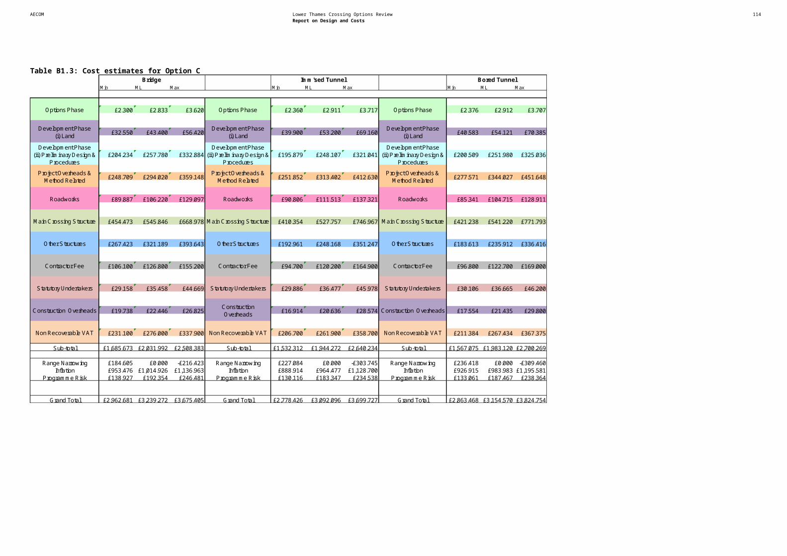
AECOM Lower Thames Crossing Options Review 116Report on Design and Costs
Route option Resource / Receptor Potential impact Avoidance options Mitigation options Supporting commentsC1 Chalk Option C1 is closer to the
residential area of Chalk (east Gravesend) and is likely to receive more adverse change in noise. Again, implementation of mitigation measures would help to control adverse impact.
C1 Orsett At Orsett, Sub Option C1 passes this area to the west and closer to Orsett Hospital. However as the alignment would be in tunnel here no adverse impact is expected. Noise barriers and low noise road surface after the tunnel emerges from portal could alleviate potential impact to the north east of Orsett.
C1 South Ockendon To the north of South Ockendon, Sub Option C1 is closer but significant impacts are likely to be controlled by mitigation.
WATER ENVIRONMENTC1 No additional constraints
have been identified.

AECOM Lower Thames Crossing Options Review 117Report on Design and Costs
Appendix D – Planning Data
Site_ID Site_Name Local Planning Authority
DA01 Eastern Quarry DartfordDA02 Northfleet Sub Station DartfordDA03 Swanscombe Peninsula West DartfordDA05 St James Pit (Stone Gate/Pit) DartfordDA06 Ebbsfleet - Station Quarter South DartfordDA07 Ebbsfleet - Station Quarter North DartfordDA10 The Bridge DartfordDA12 The Tank DartfordDA13 Land at London Rd/Craylands Ln DartfordDA15 Land Between Jct of Manor Way & London Rd DartfordDA17 Waterstone Park Phase 2 DartfordDA19 Littlebrook Complex DartfordDA20 Crossways DartfordDA21 Thames Europort DartfordDA22 Former Everards Site DartfordDA23 Northern Gateway DartfordGR03 Ebbsfleet - Northfleet Rise Quarter GraveshamGR04 Northfleet Embankment East and West GraveshamGR05 Springhead Park GraveshamGR08 Great Clane Lane Marshes* ~ GraveshamGR09 East of Thong Lane* GraveshamGR10 South of Astra Drive* GraveshamTH01 Bata Field, East Tilbury ThurrockTH02 Land North of Tilbury, adj Dock Approach Road, Tilbury ThurrockTH03 Thurrock Park, Little Thurrock ThurrockTH04 Thurrock Park, Little Thurrock ThurrockTH05 Former Pump House, Curzon Drive, Grays ThurrockTH06 LaFarge Jetty Site, West Thurrock ThurrockTH07 Land adjoining Van den Bergh & Jurgens, West Thurrock ThurrockTH08 Bluelands (West), Purfleet ThurrockTH09 Land at Manor Road ThurrockTH10 Aveley Village Extension ThurrockTH11 Aveley Football Ground ThurrockTH12 Arisdale Industrial Estate ThurrockTH13 Bata, Thames Industrial Estate ThurrockTH14 Thames Industrial Estate, Princess Margaret Rd ThurrockTO01 St Peters Pit Wouldham Tonbridge&MallingTO02 Holborough Quarry Snodland Tonbridge&MallingTO03 Bushey Wood Tonbridge&Malling