Embed Size (px)
Citation preview

Page 1
REQUEST FOR PROPOSAL (RFP)
for
FABRICATION, ASSEMBLY, TEST &
EVALUATION
of
L1 & L5 Band
LNA Filter Module
SPACE APPLICATIONS CENTRE
INDIAN SPACE RESEARCH ORGANISATION
GOVERNMENT OF INDIA
AHMEDABAD - 380 015
INDIA

Page 2
About the RFP:
Space Applications Centre (SAC), Ahmedabad, a unit of Indian Space Research
Organization (ISRO), requests vendor to submit quotation for the fabrication,
assembly, testing and evaluation of L1& L5 Band Low Noise Amplifier (LNA) Filter
module as detailed in this Request for Proposal (RFP).
The details of this are given in the following sections:
Exhibit A: Introduction & Scope of Work
Exhibit B: Design Details of L1 & L5 Band LNA & Filter
Module
Exhibit C: Details of the components used in LNA
Exhibit D: Circuits List, sizes and details
Exhibit E: Test setup details
Exhibit F: R&QA requirement
Page 3
EXHIBIT A
Introduction & Scope of Work:
1. Introduction
Space Applications Centre, Ahmedabad (SAC), a unit of Indian Space Research
Organization (ISRO) had successfully developed L1 & L5 Band LNA and Filter module.
This Request for Proposal (RFP) is for the start-to-end fabrication and delivery of the
LNA Filter module as per ISRO’s already proven designs.
2. Scope of Work
The vendor is required to fabricate, test and characterize LNA as per ISRO’s
approved drawings and fabrication sequence.
It comprises of MIC based circuit and PCB circuit having distributed / discrete
components.
Dual band filter will be given as part of free issue material(FIM).
Integration of LNA and Filter in integrated LNA Filter module assembly as per
approved drawing and fabrication sequence.
Test and Evaluation(T&E) of LNA Filter module as per approved T&E document.
The LNA Filter module needs to be fabricated following & conforming to the
Reliability & Quality Assurance (R&QA) requirements.
The fabrication of LNA Filter module includes:
1) Procurement of all components of LNA as per procurement specifications
approved by QA SAC.
2) Fabrication of LNA’s PCB circuit substrates as per approved drawings provided
and as per ISRO guidelines. SAC will provide dxf / gerber and dimension drawings of
PCB card.
3) Gold plated carrier plates, MIC, LNA housing, feed thrus and SMA connector
required for LNA fabrication will be provided as free issue material (FIM).
4) Component mounting/populating and assembly of LNA’s MIC circuit and PCB
Circuit as per the assembly drawing and fabrication sequence. The circuits need to be
assembled in mechanical housing and performance test is to be carried out. Measured
results of LNA meeting the specifications have to be demonstrated to SAC engineers.

Page 4
In case of any deviations from the specifications, the performance needs to be
optimized.
5) Dual band Filter will be provided as FIM.
6) Integration of LNA and dual band filter in an integrated LNA Filter module
housing as per assembly drawing.
7) Carrying out Test and Evaluation of LNA Filter module as per Test and Evaluation
documents.
Note:
1. The Vendor shall be responsible for carrying out the activities mentioned above and
also for actions arising out of non-conformances at various stages.
2. SAC approved bill of material to be provided by SAC
3. The TBD components, if any, will be included in the final fabrication document.
While procuring the passive components like capacitors and resistors the vendor
should also make sure to procure a range of components with electrical values nearby
the desired value for final optimization. The quotation submitted should also take
into account for these extra components, based on vendors past experiences in
developing RF subsystems.
Detailed Quantum of Work:
The total work briefly described above for the fabrication of the LNA Filter module is
detailed in upcoming section for convenience of the vendor for understanding the
quantum of work involved. The total work can be typically divided in the following
stages,
(A) Electronic Fabrication
(B) Procurement of Electronic parts, material and inspection
(C) Components mounting, assembly and packaging
(D) Testing and performance optimization of LNA
(E) Integration of LNA with Filter and characterization of integrated LNA Filter
module
(F) Data review by SAC
(G) Environmental testing
Page 5
(H) Review of Test results by SAC
The fabrication activities are to be carried out by vendor as per SAC/ISRO qualified
processes and by SAC approved vendors, with quality control at each step, as per the
SAC approved fabrication and test documents. Activities in detail are given as below:
A) Electronic Fabrication
i) Fabrication of bare PCB from ISRO approved vendor, on FR4 (glass epoxy)
laminates (Four Layers) as per approved dxf/gerber file provided by SAC.
Post-fabrication compatibility check is performed to ensure the mechanical
compatibility of package & PCB.
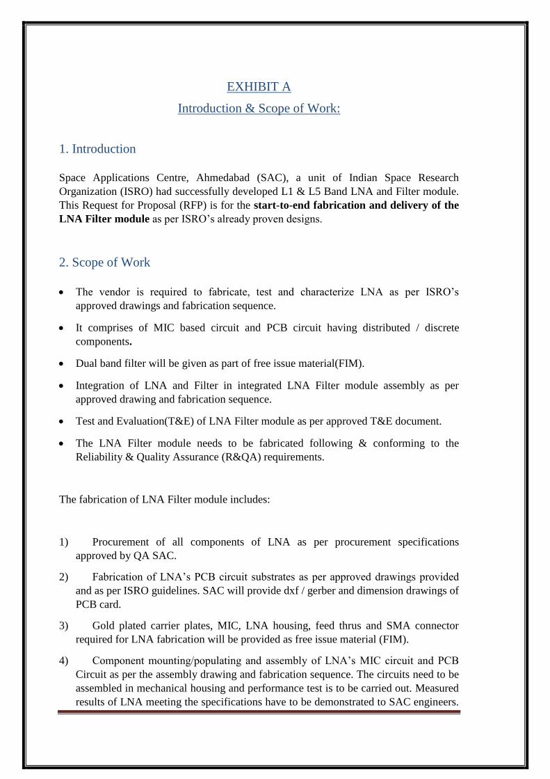
B) Procurement of Mechanical and Electronic parts, material and inspection
i) Procurement of all electronic and miscellaneous components as enlisted in
EXHIBIT B, C, D & E along with TBDs except the following FIM:
List of FIM
Sr.
No. Component / Package Type/Grade.
1 FC 40 Feed thru Hi rel
2 FP100 Feed Thru Hi rel
3 MIC substrates (as per list in Exhibit D)
3 MIC Connector Tab Type Hi rel
4 Gold Plated Kovar CP
5 Gold Plated LNA and LNA Filter module housing
6 Dual Band Filter
ii) Inspection of incoming parts and materials.

Page 6
C) Component mounting, assembly and packaging of LNA as per the following
processes:
i) Attachment of Alumina substrates on carrier-plates using reflow soldering.
ii) Mounting of components like chip capacitors, resistors, wires, active devices on
MIC and PCB by suitable techniques mentioned in fabrication sequence.
iii) Ribbon bonding from one substrate to another substrate.
iv) Fitting of MIC and PCBs in mechanical housing.
v) Assembled package wiring
vi) RF absorber and getter material mounting on Al alloy cover
vii) Conductive RTV application
The fabrication sequence may be modified depending upon fabrication
processes.
D) Testing and Performance Optimization of LNA:
The unit testing is carried out in following phases:
i) Functional Testing & Optimization
ii) Temperature compensation for finalizing the TBD values.
iii) Verification of performance of the sub-system over given temperature range.
E) Integration and characterization of LNA Filter module as per the following
process:
i) Fabrication and testing of flexible RF cable (MF141) assemblies
ii) Assembly and interconnection of LNA, Filter and 9 pin D-type connector in
integrated LNA filter housing.
iii) RTV application
iv) Functional testing as per specification listed in EXHIBIT E.
F) Data Review by SAC
G) Environmental testing

Page 7
Each unit (LNA Filter module) shall go through environmental test. These test will be
carried out on each unit to verify the workmanship and performance of the unit under
given operating conditions. It includes vibration test and thermal test as per exhibit E.
H) Review of Test results by SAC
Notes:
(1) The units are required to undergo the above tests successfully, meeting all the
specifications, before delivery to SAC.
(2) Vendor should have capability in terms of fabrication facility, storage facility and
test facility as well as necessary technical expertise to build, optimize, test and
deliver the high reliability product.
2.1 Responsibilities
The following table defines the responsibilities between SAC and the vendor.
Sr.
No. Activity Responsibility
1. Fabrication document ( SAC approved mechanical drawings,
components list, assembly details and fabrication sequence) SAC
2. Testing Procedures (To be prepared by Vendor and to be
reviewed and approved by SAC). Vendor
3. Providing FIM as per list given in Exhibit A SAC
4. Procurement of all electronic parts as per Exhibit C & D and
all raw materials & consumable and their incoming inspection
& batch acceptance tests / COC Vendor
5. Providing Gerber/DXF files of PCB of LNA SAC
6. Photo films/masks for PCB fabrication and its QC Vendor
7. Electrical Hardware Fabrication and QC (Including bare PCB
fabrication and external DC harness) Vendor
8. Assembly and packaging of RF section of LNA Vendor
9. Assembly of substrates, PCB and interconnection of LNA Vendor
10. Absorber fixing on RF cover of LNA Vendor
11. Calibrated Test Equipment & Facilities Vendor
12. Functional testing, tuning and optimisation of LNA Vendor

Page 8
13. RTV and araldite application in LNA Vendor
14. Audit on vendor QC cleared LNA unit SAC
15. Cover closing clearance & cover closing of LNA Vendor
16. Fabrication and testing of MF141 flexible cable Vendor
17. Integration of SAC supplied Filter and LNA in LNA Filter
housing
Vendor
18. RTV and araldite application in LNA Filter module Vendor
19. Functional testing of LNA Filter module Vendor
20. Audit on vendor QC cleared LNA Filter module SAC
21. Cover closing clearance & cover closing of LNA Filter
module
Vendor
22. Final functional verification and temperature test data of LNA
Filter module Vendor
23. Documentation of test results & compliance chart Vendor
24. Rework and re-optimisation, if required at any stage Vendor
25. Test and Evaluation Vendor
26. Documentation of test results & compliance chart Vendor
27. Review of test results & shipment clearance SAC
28. Delivery of Fabricated units at SAC Vendor
2.2 Delivery Schedule
Activity
Activity
Carried by
Activity
Duration
(Months)
Delivery of all approved drawings,
fabrication sequence & bill of material
SAC To+0.5
Fabrication, testing and delivery of 1 QM
unit of LNA Filter module
To + 2.5 = T1

Page 9
Fabrication, testing and delivery of 20 FM
unit of LNA Filter module
Vendor 2 Units in
every month
after T1
Notes:
1. A detailed delivery schedule shall be presented in a bar chart form showing
sequence and time of all important activities e.g. fabrication, assembly,
performance testing and final test and evaluation for future monitoring of the
project.
2. FIM will be provided to vendor by SAC as when required (to maintain delivery of 2
units of LNA filter module every month)
2.3 Vendor Selection Criteria:
Vendor should have the following at the time of bid:
Bidder shall be an “Established indigenous industry”.
Minimum Class 1,00,000 clean room
Fabrication line qualified by ISRO as per ISRO-PAX-300/305
ISRO certified fabricator/ inspector for Hi-Rel fabrication activities
Previous experience of working with MIC and PCB fabrication & testing
for Hi-Rel applications.
Experience of fabrication and testing of FM hardware for ISRO payload
applications
Test and measurement equipments and storage facility in-house
availability Documents/ certificate for above should be submitted to access vendor
capabilities, technical expertise to build, optimize, test and deliver the high
reliability product.
2.4 Guidelines / Information to Vendor
The Vendor is requested to examine the RFP thoroughly and offer compliance / non-
compliance point by point while specifying its offered value against the specification.
Since the information is proprietary to SAC-ISRO, all necessary documents
mentioned in this RFP will be shared after the order is placed.

Page 10
Any clarification regarding this RFP if required may be obtained before submitting
the quotation.
2.5 Proprietary Rights
All Documents, Designs, Layouts, Specifications and developed circuits for this activity
will be the property of SAC and without permission of SAC it shall not be shared or
provided to any third party.
2.6 Deliverables
i. LNA Filter module as per purchase order.
ii. Characterization data and report of LNA filter module.
iii. Test and evaluation data and report mentioning all results compliances and non-
compliances against the mentioned specifications.
iv. Systematic Log-history of all fabrication processes of LNA with values and
identification numbers of all components and material assembled during the
fabrication phase.
v. Systematic report and data on deviation of fabrication processes, including change
of components with proof of approval from SAC for the same.
vi. All report related to non-conformances of all stages of fabrication.
vii. COC of ordered item
Delivery Norms
All circuits and subsystems should have clearly readable identification marking on
them, as per SAC’s defined nomenclature. All reports, history sheets and data
should refer these markings only.

Page 11
EXHIBIT B:
Design Details of L1 & L5 Band Low Noise Amplifier and Filter:
Low Noise Amplifier:
The details of L1 & L5 Band Low Noise Amplifier to be developed is given below:
L1 & L5 Band LNA provided low noise amplification at 1.1764 GHz and
1.57542 GHz Band with 50 Ohm RF IP and OP interface.
Specifications
Table 2.1.1 : Specifications of Low Noise Amplifier
Sr.
No.
PARAMETER
Unit SPECIFICATION
L1 L5
1 Frequency Band MHz 1176.45 ±2 1575.42 ± 2
2 Gain dB >33 >33
3 Noise Figure dB <1.3 <1.4
4 Return Loss at
Input/ Output
dB >14 >14
5 1 dB
Compression
Point
dBm >11.0 >11.0
6 RF Interface:
Input/ Output
SMA-F
7 Power Supply +/- 5 V, 80 mA
8 Dimensions mm 85 X 73 X 35

Page 12
Design Philosophy
LNA has been built in balanced microstrip configuration. Its main components are given
below.
Balance LNA: L1 & L5 band two stage balance LNA on 25 mil Alumina
Bias Card: Bias distributing network for microstrip circuit. Developed on 4-layer FR-
4 substrate.
Total number of circuits:
1. 1 number of MIC based circuits on Alumina substrate: These circuits consist of
microstrip line based two stage balance low noise amplifier.
2. 1 numbers of FR4 (4 layer) PCB based circuit.
Package Details
LNA is housed in H-box mechanical housing with top side MIC mounting
and bottom side PCB mounting. Figure 1 shows the integrated LNA.
Fig. 1 Assembly drawing of Integrated LNA ( MIC Side)

Page 13
Fig.2 LNA Package (Top View) Fig.3 LNA Package (Bottom View)
Mechanical housing is gold plated.
Package Material = Aluminum
L1 & L5 Band Filter: Dual band filter will be provided as an FIM. Following is the
specification of filter:
Table 2.1.2 : Specifications of Low Noise Amplifier
Sr No Parameter Unit Specification
L5 L1
1 Passband MHz 1176.45 ±2 1575.42 ± 2
2 Insertion Loss dB <1.0 <1.0
3 Return loss at input and output
ports
dB >14 >14
4
Filter rejection at:
1350MHz, 2000MHz, 2211MHz,
2237.5MHz,
2259MHz, 2275MHz, 5510MHz,
5775MHz and 5790MHz
dB
>55
5 Group delay ns <10
6 RF Interface: Input/ Output SMA-F

Page 14
LNA Filter Module: Following is the specification of integrated LNA Filter module:
Table 2.1.3 : Specifications of LNA Filter Module
Sr
No Parameter Unit
Specification
L5 L1
1 Frequency Band MHz 1176.45 ±2 1575.42 ± 2
2 Gain dB >32 >32
3 Noise Figure dB <2.5 <2.6
4 Return Loss
Input
Output
dB
>11
>14
>11
>14
5 1 dB Compression Point dBm >11.0 >11.0
6 Filter rejection at:
1350MHz, 2000MHz,
2211MHz, 2237.5MHz,
2259MHz, 2275MHz,
5510MHz, 5775MHz and
5790MHz
dB
>55
7 RF Interface: Input/ Output SMA-F
8 Size mm 150 X 150 X 70 , approx..
*Spurious specifications for EMI/EMC test will be provided at the time of testing of units
LNA and filter will be integrated in an LNA filter module housing. LNA and filter will be
interconnected using flexible RF cable (MF141) and power supply of LNA will be
provided from 9-pin D-type connector.

Page 15
Fig.4: Assembly drawing of integrated LNA Filter module

Page 11
EXHIBIT C:
Details of the components used in LNA
The vendor has to procure all MIL grade components required for the fabrication of LNA as per R&QA requirement in EXHIBIT F.
The detailed component list is provided below:
Sr.
No.
Component /
Package Style Type/Part NO.
Procurement
Information Suggested MFR / VENDOR
TOTAL
Quantity
for 1 unit
of LNA
1. BJT / SURFACE
MOUNT BFY 740 Hi-rel INFINEON 4
2. Ground Lugs Hi-rel 1
3. Absorber sheets
4.5GHz SF-4.5 (18"X12") size
Hi-rel
eccosorb 1 sheet
each
4. GASKETS for
package
Hi-rel
5. Cu-Mg Wires
6. Adhesive for
fixing absorbers
7. Fasteners

Page 12
Sr
No.
Component
/ Package
Style
Type/Part
NO. TOL Rating
Procurement
Information
Suggested
MFR /
VENDOR
TOTAL
Quantity for
1 unit of
LNA
1 CDR12 Capacitor ±0.1pF 150V dc MIL-PRF-55681, R or
better AVX/ATC 14
2 CDR12 Capacitor ±0.1pF 150Vdc MIL-PRF-55681, R or
better ATC 10
3 CDR32 Capacitor ±10% 100Vdc MIL-PRF-55681, R or
better VISHAY 10
4 CDR35 Capacitor ±10% 100Vdc MIL-PRF-55681, R or
better VISHAY 2

Page 13
Sr.
No.
Component /
Package Style
Type/Part
NO. TOL Rating
Procurement
Information
TOTAL
Quantity
for 1 unit
of LNA
1 CHIP
(RM0705) Resistor ± 2% 50mW
MIL-PRF-55342, R or
better
6
2 CHIP
(RM0705) Resistor ±2% 50mW 2
3 CHIP
(RM0705) Resistor ±2% 50mW 6
4 CHIP
(RM0805) Resistor ± 1% 1W 1
5 CHIP
(RM0805) Resistor ± 1% 1W 1
6 CHIP
(RM0805) Resistor ± 1% 1W 1
7 CHIP
(RM0805) Resistor ± 1% 1W 1

Page 14
Sr.
No.
Component /
Package Style
Type/Part
NO. TOL Rating
Procurement
Information
TOTAL
Quantity
for 1 unit
of LNA
8 CHIP
(RM0805) Resistor ± 1% 1W
MIL-PRF-55342, R or
better
1
9 CHIP
(RM0805) Resistor ± 1% 1W 1
10 CHIP
(RM0805) Resistor ± 1% 1W 1
11 CHIP
(RM0805) Resistor ± 1% 1W 1
12 CHIP
(RM0805) Resistor ± 1% 1W 1
13 CHIP
(RM0805) Resistor ± 1% 1W 1
14 CHIP
(RM0805) Resistor ± 1% 1W 1

Page 15
Sr.
No.
Component /
Package Style
Type/Part
NO. TOL Rating
Procurement
Information
TOTAL
Quantity
for 1 unit
of LNA
15 CHIP
(RM0805) Resistor ± 1% 1W
MIL-PRF-55342, R or
better
1
16 CHIP
(RM0805) Resistor ± 1% 250mW 1
17 CHIP
(RM0805) Resistor ± 1% 250mW 1
18 CHIP
(RM0805) Resistor ± 1% 250mW 1
19 CHIP
(RM0805) Resistor ± 1% 250mW 1
20 CHIP
(RM0805) Resistor ± 1% 250mW 1
21 CHIP
(RM0805) Resistor ± 1% 250mW 1

Page 16
Sr.
No.
Component /
Package Style
Type/Part
NO. TOL Rating
Procurement
Information
TOTAL
Quantity
for 1 unit
of LNA
22 CHIP
(RM0805) Resistor ± 1% 250mW
MIL-PRF-55342, R or
better
1
23 CHIP
(RM0805) Resistor ± 1% 250mW 1
24 CHIP
(RM0805) Resistor ± 1% 250mW 1
25 CHIP
(RM0805) Resistor ± 1% 250mW 1
26 CHIP
(RM0805) Resistor ± 1% 250mW 1

Page 17
Sr.
No.
Component /
Package Style
Type/Part
NO. TOL Rating
Procurement
Information
TOTAL
Quantity
for 1 unit
of LNA
27 CHIP
(RM0805) Resistor ± 1% 250mW
MIL-PRF-55342, R or
better
1

EXHIBIT D:
Circuits List, sizes and details
The detailed circuit lists for LNA is provided below:
PCB based circuit
Sr.
No. PCBName
PCB Size
(mm x mm)
PCB
thickness
(mm)
Qty Substrate
1 LNA Bias
Card 75X40 1.6 1
FR4
(4layer)
MIC based circuit
Sr. No. MIC Name MIC Size (mm x
mm)
MIC thickness
(mm) Qty Substrate
1 LNA-IP 15.6X25.4 0.653 1 25 mil Alumina-
2Layer
2 LNA-Inter stage 20.4X25.4 0.653 1 25 mil Alumina-
2Layer
3 LNA-OP 15.6X25.4 0.653 1 25 mil Alumina-
2Layer
4 Link card 12.7X25.4 0.635 1 25mil Alumina-
3Layer
General Details of the MIC and PCB circuits:
Vendor has to fabricate PCB circuit used in LNA listed above.
For the fabrication of PCB circuit, following will be provided by SAC.
dxf/gerber of the circuit to be fabricated.
Dimension drawing of the circuit.
PCB design is on FR4 substrate (Er=4.7) with 1 ounce of Cu metallization. All the
PCBs are to be marked with unique card code number as mentioned. Also PCB’s
with the same card code number should be marked with unique identity number.

VECTOR NETWORK
ANALYZER
RECEIVER UUT
with DC Supply
I/P
OP
EXHIBIT D:
TEST SETUP DETAILS
Coaxial cables used during measurement, will be calibrated separately and corresponding losses
will be deducted from measurements.
1. Noise Figure
Noise Figure measurement is done using Noise Figure Analyzer. The first step is calibration and
is done without the DUT in place. After calibration, DUT is inserted and measurement is
repeated.
Noise Figure measurement set up is shown below.
FIG. 5 TEST SETUP FOR NOISE FIGURE MEASUREMENT
2.Gain, Input and Output Return Loss and Rejection measurement
Gain and input & output return loss measurement is done using vector network analyzer.
FIG. 6 TEST SETUP FOR GAIN AND RETURN LOSS MEASUREMENT
NOISE SOURCE DRIVE
O/P NOISE
SOURCE
I/P
CALIBRATION
LNA UUT with DC Supply
INPUT
NOISE FIGURE
ANALYZER

VECTOR NETWORK
ANALYZER
RECEIVER UUT
with DC Supply
I/P
OP
Power Meter
3. P1dB Measurement
The P1dB will be measured on VNA with VNA input power calibration using power meter and
two port S-parameter calibration.
FIG. 7 TEST SETUP FOR P1dB MEASUREMENT
SUMMARY OF TEST RESULTS
MODEL : FM
UNIT : LNA
I.D.NO. : LNA-
PARAMETER SPECIFICATION IBT
POST VIB.
TEST COLD TOT HOT TOT FBT
L1 L5 L1 L5 L1 L5 L1 L5 L1 L5
Noise Figure
Gain
IP Return Loss
OP Return Loss
P1dB
Rejection
DC Voltage
DC Current

EXHIBIT F:
R&QA requirement of fabrication & testing of LNA filter module
Para
No. Notes
Vendor’s
Compliance
1.0 INTRODUCTION:
This section describes the Reliability and Quality Assurance
requirements to be followed by Vendor during fabrication,
assembly and testing of ordered subsystems.
Mandatory requirements: It is mandatory that ISRO qualified
PCB and MIC fabrication and assembly process line of the
vendor including fabricator & inspector shall be used for
fabrication of ordered units. Necessary certificate shall be
attached along with the quote. SAC may visit the vendor facility
to access their capability after receiving the quote.
Vendor shall have capability in terms of SAC/ISRO qualified
fabrication, test and storage facilities as well as necessary
technical expertise to build, optimize, test and deliver the high
reliability product.
2.0 APPLICABLE DOCUMENTS:
Following workmanship standard shall be followed during
realization of the hardware.
ISRO-PAX-300
Issue-5, Nov 2012
Workmanship Standards for the Fabrication of Electronic
Packages
ISRO-PAX-305 Qualification requirements and Workmanship Standard for
Microwave Integrated Circuits (MIC)
3.0 RELIABILITY:
3.1 Operating condition for Active Components:
The electrical designs are made compliant to the SAC derating
requirements. During optimization the electrical operating
conditions of active devices shall be selected such that junction/

Para
No. Notes
Vendor’s
Compliance
channel temperatures of all solid-state devices shall not exceed
+110ºC for Silicon and GaAs under nominal operating (RF ON
in case of RF active components) and worst case environmental
conditions.
4.0 ENVIRONMENTAL SPECIFICATIONS
4.1 Operating Environment:
The unit shall meet all the performance requirements as given in
electrical specifications under the following environmental
conditions:
a) Temp. Range :
i) Flight Acceptance : 10°C to 60oC
ii) Proto Flight / Qualification : 5oC to +70oC
b) Pressure: The unit shall be capable of operating and
compliant to the specifications at ambient pressure as well as
vacuum level of 10-5 torr or batter
Note: All temperatures are referred to the base plate.
Temperature up to +60oC of base plate should not affect the life,
operation and performance of the unit.
4.2 EMI / EMC :
EMI / EMC requirements of MIL-STD-461E (Test applicability of
are shown in Table-2)
Unit shall meet Radiated Susceptibility requirements of MIL-STD-
461E.
4.3 Space Radiation:
Radiation shielding shall be carried out by the vendor as per
SAC approved drawing.
5.0 PARTS:
5.1 Electronic Parts:
Following quality level of part are to be procured for QM / FM.
TABLE-2: PARTS QUALITY

Para
No. Notes
Vendor’s
Compliance
(whichever device family applicable) Device Family Quality Level
Active devices MIL Temperature grade
Passive devices MIL Temperature grade
Multi-pin / SMA
connectors MIL Temperature grade
1. Procurement specifications for components shall be
generated by the Vendor and provided to SAC for review &
approval, before procurement. All the components shall be
procured with manufacturer COC and data pack.
2. Vendor shall ensure that all the parts and fabricated
hardware are stored under controlled environment in a
Bonded-Store till their actual use as per procedure outlined in
ISRO-PAS-207.
5.2 Mechanical parts:
Mechanical packages, boxes, covers, clamps, CPs, patterned
substrates, PCBs, test jig etc. shall be fabricated by Vendor /
Sub-vendor as per SAC supplied approved drawings including
their plating / coating.
All the bought out mechanical components including fasteners,
spring, plain washers, nuts etc. shall be procured by the vendor in
accordance with procurement specifications approved by SAC.
Following traceability information shall be maintained by the
vendor for records & submitted to SAC as a part of data package.
a) Raw material identification details, relevant in-house incoming
inspection & test reports.
b) Materials batch / lot Nos. information
c) Inspection reports for both bought out & in-house fabricated

Para
No. Notes
Vendor’s
Compliance
hardware.
d) Certificate of Compliance (CoC) supplied by sub-
vendor/manufacturer for bought out items.
6.0 INSPECTION OF PARTS :
6.1 Electronic parts
All the active and passive electronic parts (packaged) shall be
subjected to incoming inspection by Vendor including batch
acceptance report of PCB and MIC (Lot No, Batch No, Date
code etc.).
CoC of inspected parts shall be submitted to SAC along with
Data package of unit.
6.2 Mechanical parts
Mechanical parts shall undergo 100% dimensional measurements and visual inspection including plating / thermal painting workmanship point of view. All inspection and clearance records for the materials shall be maintained by the vendor. Only approved and cleared materials shall be used.
7.0 MATERIALS:
Vendor shall ensure to use ISRO approved / qualified materials.
Procurement of all the mechanical and electronic fabrication
materials shall be done as per SAC Approved Materials List
(DML). Vendor shall review & clear Material Test Report (MTR) &
CoC of the manufacturer. Non-metallic materials shall have a
Total Mass Loss (TML) of less than 1% and Collectable Volatile
Condensable Materials (CVCM) of less than 0.1% when
subjected to a test condition of +125ºC and 1x10-06 torr pressure
for 24 hours. If CoC contains outgassing parameters, then
separate test not required. All inspection and clearance records
for the materials shall be maintained by the vendor.
Materials list consisting of the name of vendor, shelf life,
qualifying agency, location of application in the sub-systems shall
be submitted to SAC for approval. Only Space qualified Printed

Para
No. Notes
Vendor’s
Compliance
Circuit Boards (PCBs), approved photo mask, patterned MICs
etc. shall be used during fabrication of hardware. Bare PCBs /
MICs shall be procured from ISRO/ESA/MIL qualified vendor.
All the materials shall be used within their shelf life.
8.0 PROCESSES:
ISRO-PAX-300 / 305 workmanship standards shall be followed
for the fabrication work. All electronic fabrication processes like
substrate metallization, pattern generation, substrate cutting,
parts mounting/assembly, etc. shall be ISRO qualified. Similarly,
the processes used for surface treatment of the box like plating
and coating in realizing the hardware shall also be ISRO
qualified. All the processes shall be carried out in accordance
with PIDs reviewed by QA-SAC.
The following electronic / mechanical fabrication processes /
activities are likely to be used for fabrication of unit.
(a) Electronic fabrication process:
1. Fabrication (Pattern engraving) on MICs on 25 mil Alumina
substrates having space qualified thin film metallization,
including PCBs.
2. Attachment of substrate on gold plated CPs
3. Passive and Active component mounting & reflow soldering
on Alumina & PCBs
4. 1 mil gold wire bonding
5. Assemblies of fabricated CPs/PCBs in gold plated Al box
6. Cu enamel wire soldering on MIC & PCB
7. Local potting & araldite application wherever ever required
as per SAC approved location diagram
Fabrication of flexible cable assembly9. Integration/harnessing

Para
No. Notes
Vendor’s
Compliance
of fabricated LNA with Filter module
(b) Mechanical Fabrication process:
1. Fabrication of mechanical packages & covers.
2. Fabrication of Kovar carrier plates.
3. Gold plating of carrier plates and aluminium packages.
4. Post gold plating machining of package, if reqd.
Fabrication work shall be carried out on ISRO qualified fabrication
line by ISRO certified operators.
9.0 QUALITY CONTROL (QC):
Vendor’s in-house Quality Control (QC) shall carry out 100%
inspection of all the fabricated / processed units as well as on-line
inspection during the electronic & mechanical fabrication activity.
9.1 QA AUDIT
If required, SAC may carry out audit on hardware accepted by
vendor QC; from both electronic & mechanical point of view on
sample basis; at various stages of realization. SAC shall audit all
related facilities, Fabrication processes, overall documentation,
including parts & materials test reports, etc.
Vendor is required to submit schedule of cover closing in
advance to SAC for audit activities.
Virtual Audit (Photographic & Documentation): Based on
confidence level build-up on fabricated hardware, SAC may opt
for virtual audit of hardware, provided vendor facility, process line,
their quality system, etc. found satisfactory. For this vendor has to
send required details along with photograph to SAC for Audit.
The Vendor shall generate close outs of discrepancies observed
during audit and submit the same to SAC for review and

Para
No. Notes
Vendor’s
Compliance
acceptance,
10.0 MARKING AND IDENTIFICATION
The units shall be identified by assigning unique serial number on
the exterior surface of both package & cover. Marking shall not
degrade the performance and quality of the unit.
Unit Name Unit Number
Contract Number Serial Number
Name of the Manufacturer Date of Mfgr.
The permanency of the marking shall be sufficient to withstand
the specified environmental testing and normal cleaning
operations using Isopropyl Alcohol and other cleaning solvents.
11.0 STORAGE and TRANSPORTATION
Storage of hardware, parts & materials:
Storage of fabricated hardware, parts & materials shall be done
as per ISRO-PAS-207. Active & Passive Component shall be
stored in controlled area environment under Class 100,000 clean
room with round the clock controlled temperature (22 ±3ºC) &
humidity (45 to 55% RH). Parts shall be stored in such manner
as to prevent damage due to undue stresses. ESD protection
care shall be taken while receiving & issue of components. A
manufacturer instruction for storage & handling of parts shall
strictly be followed during the storage. Dry N2 (Nitrogen) purged
packaging and storage cabinets shall be used for storage of
critical components like MMIC bare dice and oxygen sensitive
items like PCBs / mechanical hardware.
Transportation:

Para
No. Notes
Vendor’s
Compliance
Suitable packing (as specified in ISRO-PAS-207) shall be
provided for the transportation of the unit by air or road without
any degradation / damage.
Each unit shall be packaged in individual ESD protective
packaging and protect the unit from environmental conditions
encountered during transportation, like heat, humidity & dust.
This individual container shall then be placed in a transportation
container. More than one individual unit may be placed in the
transportation container. The transportation container shall
protect the units from heat, humidity, dust, mechanical shock &
vibrations during transportation.
The individual unit packages and transportation containers shall
be clearly marked with following instructions along with other
mandatory markings.
“ESD sensitive units”
“To be opened only under clean environment with ESD
precautions”
“High reliability space usage systems”
12.0 MODEL PHYLOSOPHY
Following Model shall be fabricated.
(a) Qualification Model (QM)
(b) Flight Model (FM)
Go ahead for QM shall be given after demonstration of
satisfactory performance of QM.
12.1 Test Applicability
Applicable tests for QM and FM are given in Table-2 below.
Table – 1: Tests applicability

Para
No. Notes
Vendor’s
Compliance
Sr.
No. Name of Test QM FM
1. Initial Bench test √ √
2. Burn-in test √
(168 Hrs)
√
(168 Hrs)
3. Post Burn-in performance test √ √
4. Humidity Test √ NA
5. Post Humidity performance test √ NA
6. Passive Thermal Cycling test √ √
7. Post thermal cycling
performance test
√ √
8. Active Sine Vibration Test √ NA
9. Post Sine Vibration elect.
performance test √ NA
10. Active Random Vibration Test √ √
11. Post random vibration elec.
Performance test √ √
12. Mechanical shock test √ NA
13. Post shock elec. performance
test √ NA
14. EMI Tests RS-103 RS-103
15. Thermo Vacuum test √ √
16. Final Bench Test √ √
Note:
1. At the end of each environmental /mechanical test, visual
inspection and electrical performance check shall be carried
out.
2. Vendor shall send the measurement data to SAC for review
& clearance for next test.
3. Suitable buffer connectors shall be provided to protect input /
output connectors of the device from wear and tear due to

Para
No. Notes
Vendor’s
Compliance
mating / de-mating with other connectors during testing.
Record of number of time mating / de-mating of connectors
shall be maintained.
12.2 Failure:
Deviation from the agreed electrical specifications shall be
treated as non-compliance, and as cause to reject the units.
Any failure observed at any stage during testing shall be reported
to SAC immediately. This shall be followed by detailed failure
analysis by Vendor clearly identifying the cause of failure as
random or design related. Any modifications required in electrical,
mechanical or fabrication process related aspects shall be
approved by SAC. In case of mechanical or electrical failures; a
retest plan or modification in the test plan may be necessary.
Based on the failure analysis, such retest plan / modified test plan
shall be decided and implemented after approval by SAC.
13.0 TEST CONDITION & DETAILS:
Following paragraphs give details of various tests to be
performed on QM / FM units. All the tests shall be conducted
using the equivalent FM Semi-Rigid cable assemblies except
vibration test.
External visual inspection shall be conducted after each
environmental test.
13.1 Physical Measurement:
All the units shall be examined for Mass and Dimensions.
Measured value shall be recorded.
13.2 Visual Inspection:
13.2.1 Internal Visual Inspection (Pre-Cap):
After completion of fabrication, internal visual inspection of the
units shall be carried out by Vendor QC to detect any
workmanship related deviation and non-conformance w.r.t
respective ISRO standards. SAC may audit the pre-cap visual

Para
No. Notes
Vendor’s
Compliance
inspection. Vendor shall inform the schedule of cover closing of
units.
13.2.2 External Visual Inspection:
All the units shall be examined visually at 10 X magnification
before and after each environmental test. The units shall be
inspected for surface finish, plating, mechanical and
workmanship related defects.
13.3 Initial Bench Test (IBT):
This test shall be performed to verify compliance to all the
electrical parameters and will be taken as reference for all
subsequent tests. Electrical parameters shall be measured as
specified.
13.4 Burn-In Test
For FM unit, burn-in shall be carried out at maximum Operating
Temperature while for QM unit, it shall be carried out at maximum
qual. Temperature, in power ‘ON’ condition. The duration of Burn-
in shall be 168 hrs. Data log for Time-Temperature shall be kept
for verification.
13.5 Post Burn-in Electrical Test:
This test shall be conducted at ambient temperature. Electrical
parameters shall be measured during Post burn-in functional
tests shall be performed.
13.6 Humidity Test:
This test shall be conducted on QM units as per the following
profile:

Para
No. Notes
Vendor’s
Compliance
Stabilize the humidity chamber at RH not less than 85% at any
temperature < 38 0C. Keep the unit inside the chamber. Follow the test
cycle. Repeat this cycle twice for a total duration of 48 hrs.
At the end of the test cycle remove the unit from the humidity chamber.
Detailed visual inspection and performance test shall be carried out
after the test. Also confirm that there is no corrosion, decolourisation,
fungus growth and any problem related to peeling off. Also examine
the connectors carefully, for any defect (under magnification, if
necessary).
13.7 Passive thermal cycling test:
QM and FM units shall be subjected to passive thermal cycling
test as per following profile. Electrical measurements shall be
carried out after the test.
Model Cold (T1) Hot (T2)
FM 10ºC 60ºC
QM 5ºC 70ºC

Para
No. Notes
Vendor’s
Compliance
13.8 Active Vibration Test:
Sine / Random vibration tests shall be carried out on applicable
QM / FM units. Visual & electrical measurement shall also be
performed after each Sine & Random vibration test. Vibration
levels given below are tentative. Levels may be changed
depending upon mechanical configuration.
Vendor shall generate a vibration test report in a standard format,
a shown in Annexure-4, which will be sent to SAC for review and
acceptance.
13.8.1 Resonance Search
Pre & Post Vibration, resonance search shall be carried out in all
the three axes as per following levels. Natural resonance
frequency (Fn) shall be greater than 100 Hz and drift in pre &
post vibration ‘Fn’ shall be within 10%.
Frequency (Hz) Amplitude
10 - 2000 0.5 g
Sweep rate 4 Oct / Minute
Vibration test sequence:
For QM Unit (all axis): LLS, Sine Vib, LLS, Functional test, LLS
Para
No. Notes
Vendor’s
Compliance
Random Vibration, LLS
For FM Unit (all axis) : LLS pre, Random vibration, LLS post.
Vendor shall use valid calibrated torque wrenches for fixture &
package mounting.
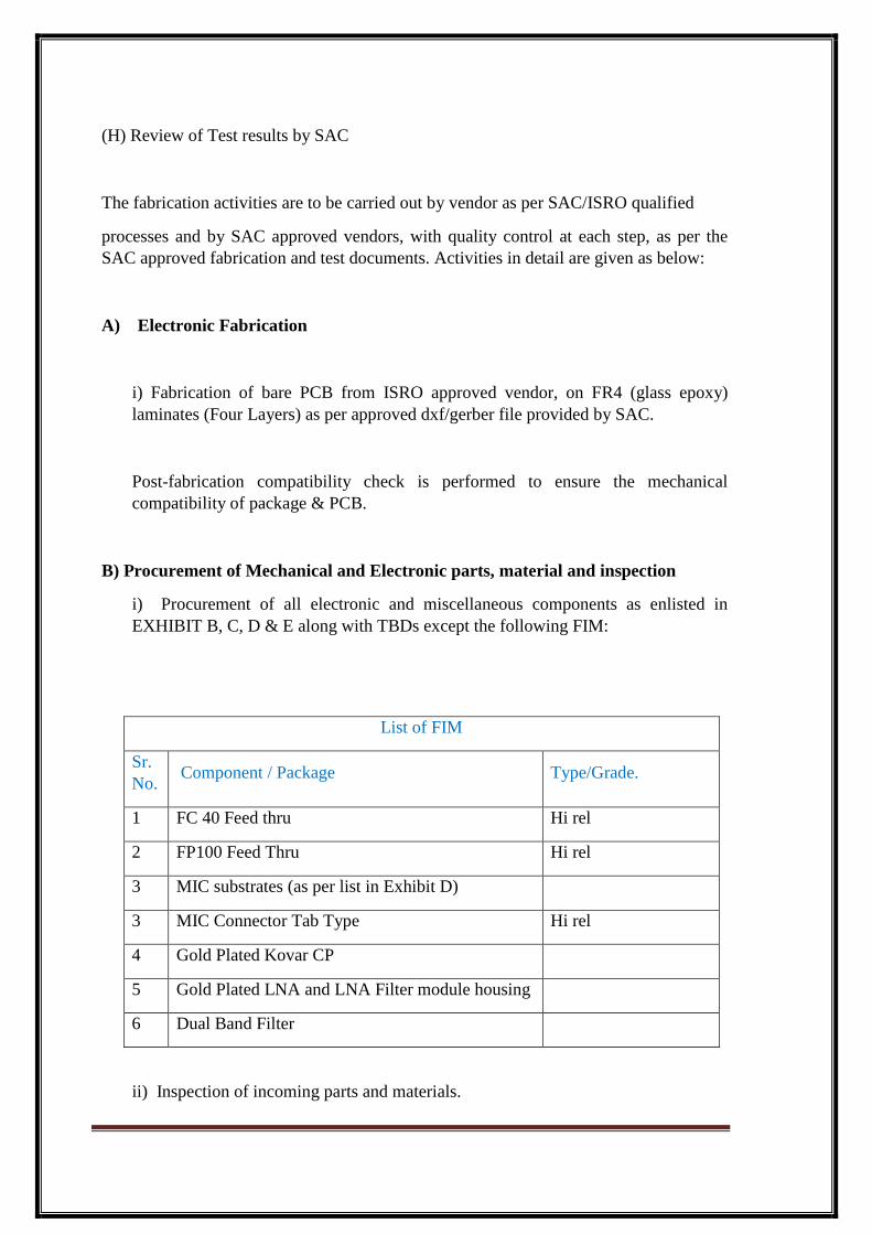
13.8.2 Sine Vibration:
Sine vibration test shall be conducted only on QM unit. The unit
shall be in operating condition for the duration of vibration test.
Gain and DC currents shall be monitored and logged
continuously during vibration.
Frequency (Hz)
Amplitude (g)
Longitudinal
Axis Lateral axis
10-16 20 mm DA 15 mm DA
16-100 10 g 6 g
Sweep rate 2 oct/min 2 oct/min
1 sweep in each axis shall be performed.
13.8.3 Random Vibration:
Units shall be subjected to random vibration tests with levels as
given below in passive mode. Frequency verses PSD plots shall
be obtained and shall be kept along with the test results for
verification.
Gain and DC currents shall be monitored and logged
continuously during vibration.
Frequency Power spectral density g2/Hz

Para
No. Notes
Vendor’s
Compliance
(Hz) QM
(X, Y & Z axis)
FM
(X, Y & Y axes)
20 0.002 0.001
68 0.002 0.001
250 0.138 0.062
1000 0.138 0.062
2000 0.034 0.015
Overall RMS 13.5 9
Duration 120 sec. 60 sec.
13.9 Mechanical Shock Test:
QM unit shall be subjected to mechanical shock test as per the
following test levels in all the 3 axes. Shock levels specified with
Q = 10.
Parameter Specifications
Acceleration 50g
Duration 10msec
Waveform Half Sine
No of Shocks 6 Shocks
(One/axis/direction)
Axis All 3 axis
(levels are tentative; it may change depending on mounting
location of the unit)
13.10 EMI /EMC Test:
RS-103 test shall be carried out at following frequencies and electrical
field levels on QM and FM Units. These frequencies levels and output
spurious specifications may be modified, and shall be informed at the
time of testing.
FREQUENCIES AND LEVELS FOR QM UNIT
Sr. No. Frequency (MHz) Field Strength
(V/m)
1 20 5

Para
No. Notes
Vendor’s
Compliance
2 30 5
3 40 5
4 49 5
5 60 5
6 80 5
7 100 5
8 150 5
9 240 5
10 402.52 to 402.85 (10kHz step size)
20
11 434 5
12 543 5
13 1310 5
14 1350 10
15 2211 20
16 2237.5 20
17 2259 20
18 2275 20
19 2720 5
20 2800 10
21 4000 5
22 5510 5
23 5660 10
24 5790 10
25 7000 5
26 8000 5
27 10000 5
FREQUENCIES AND LEVELS FOR FM UNITS
Sr. No. Frequency (MHz) Field Strength
(V/m)
1 49 5
2 402.52 to 402.85 (10kHz step size)
20
3 434 5
4 1310 5
5 1350 10
6 2211 20
Para
No. Notes
Vendor’s
Compliance
7 2237.5 20
8 2259 20
9 2275 20
10 2720 5
11 2800 10
12 5510 5
13 5660 10
14 5790 10
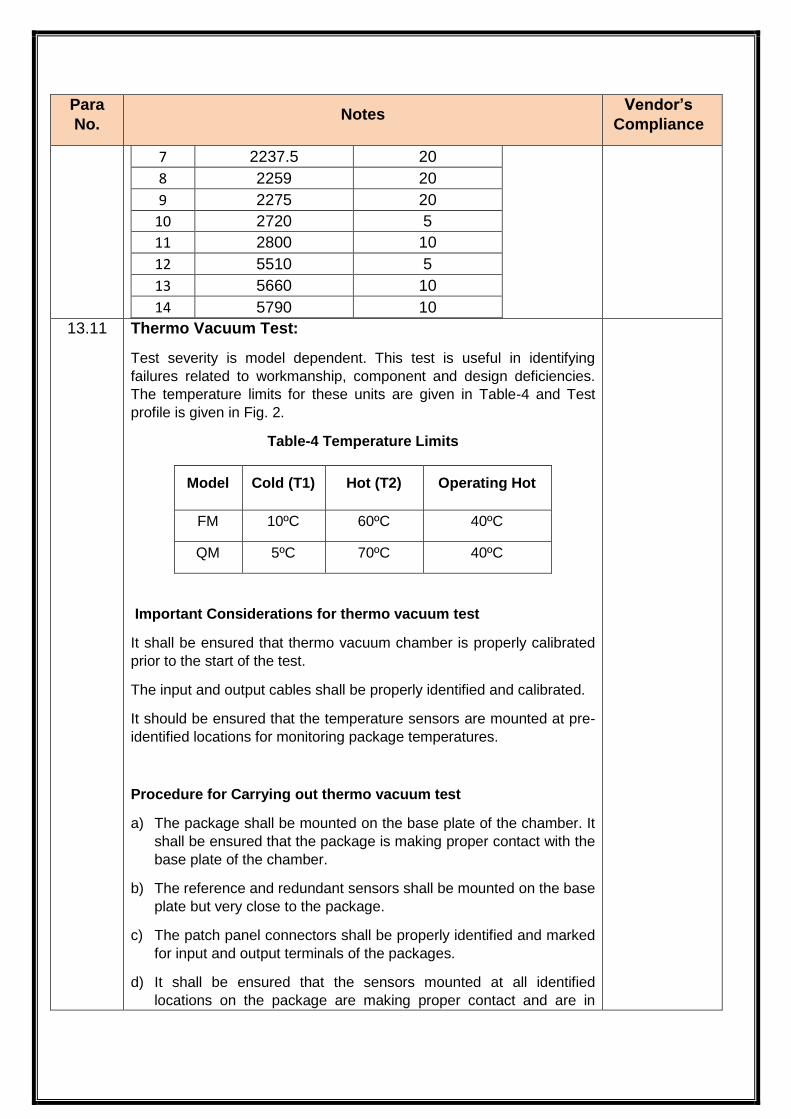
13.11 Thermo Vacuum Test:
Test severity is model dependent. This test is useful in identifying
failures related to workmanship, component and design deficiencies.
The temperature limits for these units are given in Table-4 and Test
profile is given in Fig. 2.
Table-4 Temperature Limits
Important Considerations for thermo vacuum test
It shall be ensured that thermo vacuum chamber is properly calibrated
prior to the start of the test.
The input and output cables shall be properly identified and calibrated.
It should be ensured that the temperature sensors are mounted at pre-
identified locations for monitoring package temperatures.
Procedure for Carrying out thermo vacuum test
a) The package shall be mounted on the base plate of the chamber. It
shall be ensured that the package is making proper contact with the
base plate of the chamber.
b) The reference and redundant sensors shall be mounted on the base
plate but very close to the package.
c) The patch panel connectors shall be properly identified and marked
for input and output terminals of the packages.
d) It shall be ensured that the sensors mounted at all identified
locations on the package are making proper contact and are in
Model Cold (T1) Hot (T2) Operating Hot
FM 10ºC 60ºC 40ºC
QM 5ºC 70ºC 40ºC

Para
No. Notes
Vendor’s
Compliance
working order.
e) Pre-thermo vacuum electrical parameter measurements at ambient
temperature and pressure in the chamber are considered as
reference for this test and are carried out in the open chamber
condition. The identified parameter measurements at pre-defined
temperatures shall be carried out after ensuring that the package
temperature has stabilized and power ON/OFF cycling is carried
out.
f) After post-thermo vacuum electrical parameter measurements at
ambient temperature and pressure in the chamber, the package
shall be taken out from the chamber and shall be inspected visually.
In case of failure of any type vendor has to inform SAC. A failure
analysis shall be required & corrective action suggested by SAC.
The unit will then undergo re-testing as per SAC recommendations.
g) Continuous monitoring and logging of gain shall be carried out
during the test.
Fig.2 Thermo Vacuum Test Profile
13.12 Final Bench Test (FBT):
The final bench test shall be conducted for measurement of
electrical parameters as given in test matrix. The test shall be
conducted at ambient temperature. All the test results shall be
recorded and any performance deviation with respect to Initial

Para
No. Notes
Vendor’s
Compliance
Bench Test shall be evaluated and shall be within specified limits.
13.13 Final Visual Inspection:
The unit shall be inspected for plating, surface, finish, mechanical
deviations, corrosion and workmanship related defects. No visual
degradation shall be allowed after completion of QM or FM test.
14.0 NON-CONFORMANCE MANAGEMENT:
Effective non-conformance management mechanism shall be
established by the vendor. Major non-conformance at any stage,
which affects the quality & reliability or the fabrication process of
entire lot, shall be reported to SAC immediately with
photographs, nature of non-conformance observed, etc.
Disposition shall be taken in consultation with QA, SAC.
However, for all the minor non-conformances, approval from SAC
is not mandatory, and shall be reviewed and discussed by the
vendor’s NCR board. Non-conformance report shall be generated
by the concerned agency and shall be reviewed and disposed-off
by the NCR board.
Any non-conformance affecting the fabrication and / or inspection
procedure shall be reported to SAC. Changes in related
documents shall be implemented and revision number of the
document shall be updated. This shall be followed by updating all
the documentation (fabrication, inspection, test etc).
All the non-conformances with the disposition given by the NCR
board shall be reported to SAC periodically. This shall be
followed by report of close out action completion, if any. For all
the non-conformance report, SAC representative shall be the
focal the person.
15.0 CONFIGURATION CHANGE CONTROL
The manufacturer shall follow an effective configuration change
control procedure during the fabrication stages. Plans for both
non-conformance and configuration change control shall be made
for submission to SAC for review and approval before initiation of
manufacturing activities.
16.0 DOCUMENT TO BE SUPPLIED :

Para
No. Notes
Vendor’s
Compliance
16.1 The following documents shall be supplied along with the quote:
a) Pont by point compliance to all the requirements of this
document.
b) Details to be provided as per QA check list given in Annexure-
3
16.2 The following documents shall be supplied during the contract:
a) Materials & Process List to be used for the fabrication of
units, detailing their quality level, procurement specifications,
traceability information, out gassing specifications etc.
b) CoC, screening (at Vendors / sub-vendors) reports, incoming
inspection report, batch acceptance test reports of Parts &
Materials
c) Record of Bias conditions of identifying the channel / junction
temperatures of all the active devices
d) Interface control drawing (AutoCAD soft copy)
e) Details of design modifications (wherever applicable) with
respect to the given details
f) Process Identification Document.
g) Test procedure documents for Qualification and Acceptance
tests with test conditions, procedures, list of equipment and
their calibration status, for review & approval by SAC
h) Non-conformance management plan
i) Configuration change control plan.
j) Program management plan
16.3 Following documents shall be supplied during the program with
respect to relevant activity.
a) Status report for the fabrication activity and test schedule.
b) Schedule for Cover closing of the QM and FM units
c) Details of test set-up and readiness
d) Non-conformance report at agreed intervals

Para
No. Notes
Vendor’s
Compliance
e) Failure Report; as and when failure occurs
16.4 Following detailed documents shall be supplied for each unit
along with deliverables, in soft copy on CD/ DVD.
a) T & E report of each unit containing detailed test results, test
history, conformance matrix, TBD value of components etc.
b) CoC of the deliverable units
c) CoC of parts & materials Including screening report
d) All fabrication details supplied by SAC for fabrication
e) Non Conformance reports with close-outs
Annexu
re-1
TEST MATRIX for QM
Sr.
No. Parameters
IBT
A/C
La
b.
Bu
rn-i
n
Po
st
Sin
e V
ibra
tio
n
Po
st
Ra
nd
om
Vib
rati
on
Po
st
Sh
oc
k
TO
T a
s P
er
Th
erm
al C
yc
le
FB
T A
/C L
ab
.
1 Gain √ √
2 Noise Figure √ √
3 Input Return Loss √ √
4 Output Return Loss √ √
5 P1dB (O/P) √ √
6 Rejection √ √
7 DC Voltage √ √
8 DC Current √ √

Para
No. Notes
Vendor’s
Compliance
Vendor’s Compliance:

Para
No. Notes
Vendor’s
Compliance
Annexu
re-2
TEST MATRIX for FM
Sr.
No. PARAMETERS
IBT
A/C
La
b.
Bu
rn-i
n
Po
st
Sin
e V
ibra
tio
n
Po
st
Ra
nd
om
Vib
rati
on
TO
T a
s P
er
Th
erm
al C
yc
le
FB
T A
/C L
ab
.
1 Gain √ √
2 Noise Figure √ √
3 Input Return Loss √ √
4 Output Return Loss √ √
5 P1dB (O/P) √ √
6 Rejection √ √
7 DC Voltage √ √
8 DC Current √ √
Vendor’s Compliance:

Para
No. Notes
Vendor’s
Compliance
Annexu
re-3
QA Check List
Vendor to provide complete details of following with relevant certificates.
Sr.
No
Details of information required Vendor
response
1 Point by Point compliance provided ? Yes / No
2 List each applicable process ISRO qualified at your /
sub-vendor’s facility, their qualification report &
qualification certificate.
Process Name Facility Certi. No.
a) Fabrication facilities: MIC /PCB
b) Component mounting & Assembly
process on,
MIC and PCB
c) Plating / Surface treatment
3 List of ISRO certified fabricator and Inspector for both
MIC and PCB work available at the time of bid.
4 Details of Test engineer with experience available at
the time of bid.
5 List of Test & Measuring instrument for optimizing RF
circuits with major specification like frequency range,
etc.
6 Location of test facilities likely to be used for following
tests shall be provided. (whichever applicable)
a) Physical Measurements
b) Visual Inspection (internal & external)
c) Electrical measurements
d) Burn-in
e) Humidity test
f) Passive thermal cycling test:

Para
No. Notes
Vendor’s
Compliance
g) Active Vibration Test (Sine & Random):
h) Mechanical Shock Test:
i) EMI /EMC Test:
j) Thermo Vacuum Test:

Para
No. Notes
Vendor’s
Compliance
Annexu
re-4

Para
No. Notes
Vendor’s
Compliance

Para
No. Notes
Vendor’s
Compliance