Embed Size (px)
Citation preview

Operation ManualService Instrument
rbr-ecom FN
rbr-Computertechnik GmbHAm großen Teich 2 D-58640 Iserlohn
Tel. (49) 2371-945.5 Fax (49) 2371-40305Email: [email protected]

INDEX
Page
1. Introduction 3
2. Equipment of the rbr-ecom FN 4
3. Instrument design 5
4. Operation rbr-ecom-FN 6
5. Store/Select customers 7
6. Service report issue6.1. General customer data 86.2. Adjustments / Texts 96.3. Material / Workmanship 96.4. Remarks / Payment 106.5 Report issue for Voksy® software 106.6. Copy function 11
7. Combustion measurement7.1. Gas analysis 127.2. Difference pressure measurement 137.3. Inputs 147.4. Measurement 2 147.5. CO measurement (safety check) 147.6. Store measurements on RAM card 15
8. Printout 15
9. Adjustments 19
10. Menu INTERNAL 20
11. Menu CONTROL 21
12. Data transfer12.1. Initialisation for Voksy® software 2212.2. Requirements for data transfer 22
13. Menu COMMUNICATION13.1. Delete functions 2313.2. Modem transfer 2313.3. Modification of item data bank 24
14. Selection tables 26
15. Maintenance advices 28
16. Technical data 30Page 2
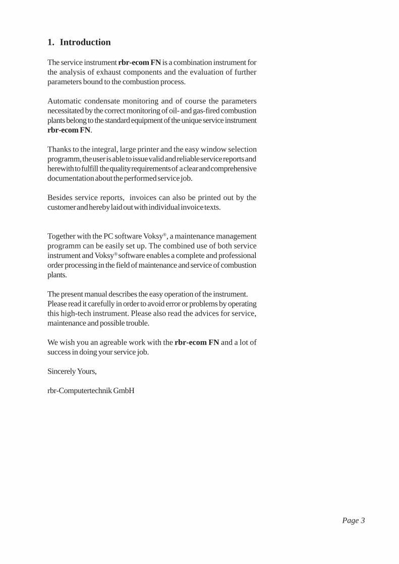
1. Introduction
The service instrument rbr-ecom FN is a combination instrument forthe analysis of exhaust components and the evaluation of furtherparameters bound to the combustion process.
Automatic condensate monitoring and of course the parametersnecessitated by the correct monitoring of oil- and gas-fired combustionplants belong to the standard equipment of the unique service instrumentrbr-ecom FN.
Thanks to the integral, large printer and the easy window selectionprogramm, the user is able to issue valid and reliable service reports andherewith to fulfill the quality requirements of a clear and comprehensivedocumentation about the performed service job.
Besides service reports, invoices can also be printed out by thecustomer and hereby laid out with individual invoice texts.
Together with the PC software Voksy®, a maintenance managementprogramm can be easily set up. The combined use of both serviceinstrument and Voksy® software enables a complete and professionalorder processing in the field of maintenance and service of combustionplants.
The present manual describes the easy operation of the instrument.Please read it carefully in order to avoid error or problems by operatingthis high-tech instrument. Please also read the advices for service,maintenance and possible trouble.
We wish you an agreable work with the rbr-ecom FN and a lot ofsuccess in doing your service job.
Sincerely Yours,
rbr-Computertechnik GmbH
Page 3

2.) Equipment of the rbr-ecom FN
Probes
Standard probe :- Suitable for the combined gas, draught and losses measurement- Insertion length probe pipe 290 mm- External diameter probe pipe 10 mm- Coaxial version with
. NiCr/Ni thermocouple (T-Gasmax.
= 500 °C). 3-chamber hose (length 3 m). Fixation cone
On request, we will enjoy to propose you different lengths (max. 1000 mm) respectively other temperatureranges (PtRh/Pt thermocouple).
Multi-hole probe (option):- Probes set for CO measurement at gas-fired plants (safety check)- 4 insertion lengths (142, 172, 182 und 205 mm)- Hose length 3 m
Temperature sensors
T-Room sensor (standard):- T-Room sensor with fixing magnet (T-Room
max. = 99 °C)
T-Room probe (option):- T-Room sensor for T-Room independent gas burners (T-Room
max. = 99 °C)
Standard delivery covering
- Condensate hose- Replacement filter- Carrying strap for transport case- Operation manual- Final calibration data sheet
Optional accessories
- RAM cards (PCMCIA norm)- Probe fixation (flexible)- Undercase-Voksy® software with initialisation programme
Page 4

RAM card slot 1
RAM card slot 2
Keyboard connection
RS 232 connection
Ejector forRAM cards
Front side
Back side
Mains power
SO2/NOx filterCondensationpump
Fresh air connection
Connectiongas temperature
Connection suckingtemperature
Connectionsampledgas
Connectiondraught
Remotedisplay
Loading control lamp
Page 5
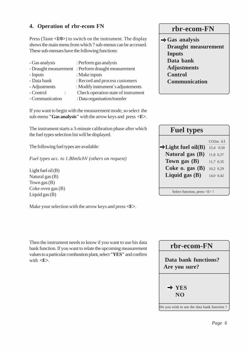
4. Operation of rbr-ecom FN
Press (Taste <I/0>) to switch on the instrument. The displayshows the main menu from which 7 sub-menus can be accessed.These sub-menues have the following functions:
- Gas analysis : Perform gas analysis- Draught measurement : Perform draught measurement- Inputs : Make inputs- Data bank : Record and process customers- Adjustments : Modify instrument´s adjustements- Control : Check operation state of instrument- Communication : Data organisation/transfer
If you want to begin with the measurement mode, so select thesub-menu "Gas analysis" with the arrow keys and press <E>.
The instrument starts a 3-minute calibration phase after whichthe fuel types selection list will be displayed.
The following fuel types are available:
Fuel types acc. to 1.BImSchV (others on request)
Light fuel oil (B)Natural gas (B)Town gas (B)Coke oven gas (B)Liquid gas (B)
Make your selection with the arrow keys and press <E>.
Then the instrument needs to know if you want to use his databank function. If you want to relate the upcoming measurementvalues to a particular combustion plant, select "YES" and confirmwith <E>.
Fuel types
Select function, press <E> !
CO2m A1
Light fuel oil(B) 15,4 0,50
Natural gas (B) 11,8 0,37
Town gas (B) 11,7 0,35
Coke o. gas (B) 10,2 0,29
Liquid gas (B) 14,0 0,42
Gas analysisDraught measurementInputsData bankAdjustmentsControlCommunication
rbr-ecom-FN
Page 6
rbr-ecom-FN
Data bank functions?Are you sure?
YESNO
Do you wish to use the data bank function ?
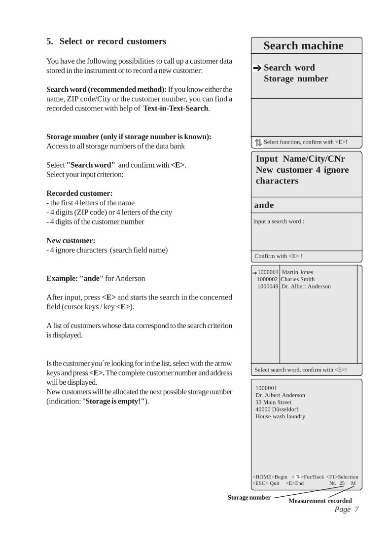
5. Select or record customers
You have the following possibilities to call up a customer datastored in the instrument or to record a new customer:
Search word (recommended method): If you know either thename, ZIP code/City or the customer number, you can find arecorded customer with help of Text-in-Text-Search.
Storage number (only if storage number is known):Access to all storage numbers of the data bank
Select "Search word" and confirm with <E>.Select your input criterion:
Recorded customer:- the first 4 letters of the name- 4 digits (ZIP code) or 4 letters of the city- 4 digits of the customer number
New customer:- 4 ignore characters (search field name)
Example: "ande" for Anderson
After input, press <E> and starts the search in the concernedfield (cursor keys / key <E>).
A list of customers whose data correspond to the search criterionis displayed.
Is the customer you´re looking for in the list, select with the arrowkeys and press <E>. The complete customer number and addresswill be displayed.New customers will be allocated the next possible storage number(indication: "Storage is empty!").
Confirm with <E> !
Input Name/City/CNrNew customer 4 ignorecharacters
Input a search word :
ande
1000001Dr. Albert Anderson33 Main Street40000 DüsseldorfHouse wash laundry
<HOME>Begin < >For/Back <F1>Selection<ESC> Quit <E>End Nr. 25 M
Measurement recordedStorage number
Search machine
Search wordStorage number
Select function, confirm with <E>!
Select search word, confirm with <E>!
1000001 Martin Jones 1000002 Charles Smith 1000049 Dr. Albert Anderson
Page 7

All data belonging to the service report is stored in the displaymasks under 4 main sections:
- General customer data- Adjustments/Texts- Material/Workmanship- Remark/Payment
Here data can be viewed, modified or recorded.
6. Service report issue
6.1. General customer data
Select the sub-menu "General customer data" with the arrowkeys and confirm with <E>. The cursor stands in the field Helpand blinks. Press <F2> to open an help file which covers themost important information for the issue of a service report .Press <ESC> to quit the help file.
Principally the report fields can be filled up as follows:- move cursor from field to field (key <F1>)- fill in one field after the other:
- fields without are input fields (input only with keyboard possible)
- fields with are selection fields (input via keyboard and take-over from recorded selection tables possible)
Please find the following explanation regarding the take-over fromelements of selection tables.Move the cursor with <F1> on the selection field "ZIP/CITY" .Press <F2> to open the attached selection table.
The available selection of cities will be displayed. Move the arrowkey on the correct city and call up with <E>.
Version 1.16 Help: F2 Report/InvoiceNr: Name: Street: ZIP/City Stand:Cust. Nr: Tel:Bank Code: Nr: km:
Manufact. Type Year Boiler BurnerNom. power kW: Load kW:
MC of: . . Service acc. MC: Work 1: Work 2: Rem.:
Search machineGeneral cust. dataAdjustments/TextsMaterial/LabourRemark/PaymentMeas. values storagePrint menu
Data bank
10000 Berlin 20000 Hamburg 30000 Hannover 40000 Düsseldorf 50000 Köln 60000 Frankfurt 70000 Stuttgart 80000 München
<E> Confirm < > Select <F1> Back
The last 3 figures relate to a maintenancecontract (given by use of the Voksy®
software). Abbreviations for inputs underWork 1 and Work 2 are e.g.:01-12 = Month the job was madeBH = Burner main revisionBI = Burner inspectionBC = Burner control revisionBC = Boiler cleaningT = Tank check
Page 8

Check twice and press <E> to take over the city in the reportfield. If needed, the input can be modified or completed.All necessary inputs can be made as described earlier.Press <ESC> to return to the upper menu level.
6.2. Adjustment / Texts
In the upper window part, load adjustment data -divided in oiland gas combustion- can be inputed or selected. In the lowerpart, trouble causes and performed jobs can be inputed.The abbreviations have the following meaning.
-L = Load adjustment (Caution: Load ajustment 1 will be later on correlated to mesurement 1!)
-P = Oil or gas pressure (in bar resp. mbar)-G = Nozzle description oil-PL = Adjustment primary air-SL = Adjustment secondary air-SS = Adjustment disk retarding-FR = Adjustment flame tube-GP = Blower pressing-I = Adjustment IRD
6.3. Material / Workmanship
The menu "Material / Workmanship" enables thedocumentation of spares replaced during the service job as wellas the works done and theit implementation in the service reportor on the invoice.After input of the amount (material or working time) in column 1,press <F1> to access the selection field for parts andworkmanship. Press <F2> to call up the catalogs stored in therbr-ecom FN.These catalogs cover current spares and labour works. Onceyou have selected one catalog with the arrow keys and <E>(e.g. working and driving times), all items respectivelyworkmanships of this catalog will be displayed.Choose e.g. "AZE Working-day Normal time" and press<E>, so this item will be displayed with the corresponding price(first 4 figures = amount DM net / last 2 figures = amount Pf net).Press again <E> to store this choice.
Version 1.16 Help: F2 Report/Invoice no.: Name: Street: ZIP/Cityt 10000 Berlin LocationCust.no.: Tel:Bank code: No: km:
Manufacturer Type Year Boiler BurnerNom. power kW: Load kW:
MC of: . . Service acc. MC: Work: Work 2: Rem.:
Oil firingL P: b G kg/h:L P: b G kg/h:
Gas firingL P: mbar l/m: m3/h:
P: mbar l/m: m3/h:Further adjustment data
PL: SL: SS: FR: GP: I: Order / Customer report
Trouble source
Jobs performed
Qty Labour and parts P-price
AZE Working day, normal time002220
<HOME>Begin < > For-/Backwards<F1> Selection <ESC> Quit <E>End Nr.
Page 9

6.4. Remark / Payment
In the last menu point "Remark / Payment" you can inputremark texts (prepared forms via <F2> or input via keyboard)for service report and invoice.
Furthermore, selection fields enable the input of organisation data.At the page end, the amounts for spares and labour works aredsiplayed (net amount; VAT amount; Total amount, Conversionrate).
Once all data for service report and invoice has been inputed,you can switch over to gas analysis (key <Menü>/"Gasanalysis"/<E>).Advice 1: A switch to gas analysis is possible any time.
Advice 2: The VAT rate is stored under "Adjustments / MenuInternal" . The rate can be modified as follows:
- Select "VAT" with the arrow keys, confirm with <E>,- Input correct rate and confirm with <E>,- Return to main menu with <Menü>.
6.5. Report issue for Voksy® software
If the rbr-ecom FN is operated together with the Voksy®
Maintenance Management Programme, the following points haveto be observed absolutely:
- a regular data exchange between FN and Voksy® software must be secured,
- if a report or an invoice is to be issued for a customer, so a report/invoice number must absolutely be designated by the FN. Otherwise Voksy® will not process the data record.
Proceed principally as follows:
- Call up customer upon search machine,- If need be, consult the data of the last report (general customer data, Adjustments/Texts, Material/Labour; Remark/Payment),- Select "General customer data" and press <E>.
Version 1.16 Help: F2 Report/Invoice no: Name: Street: ZIP/City LocationCust. Nr: Tel:Bank Code: Nr: km:
Manufacturer Type Yr Boiler BurnerNom. power kW: Load kW:
MC of: . . Service acc. MC: Work 1: Work 2: Rem.:
Page 10
Remark text for service report
Remark text for invoice
Internal remark text
Service engineer Order passed by Payment textBank w: / % dis. Print signature:
Net. VAT Tot.Conversion currency EURO

rbr-ecom-FN
Select function, confirm with <E> !
New report / Invoice numberCancel report / Invoice numberCancel measurementsAdd invoice numberWarranty without discountWarranty with discount
rbr-ecom FN
Are you sure ?
YESNO
New report /Invoice number
Quit with <ESC> !
- Press simultaneously <Shift> + <F2>,- Select "New report / Invoice number" and confirm with <E>,- Answer question with "YES":
- new report/invoice number will automatically be allocated (in the succession)- all data of the last report (excepted "General customer data" and "Adjustment") will be erased
- Press <ESC> to turn back to "General customer data"- Issue new report.
Advice:All other functions, excepted "New report / Invoicenumber" are special cases and are normally not needed:
- Cancel report / invoice number:- Report / Invoice number will be cancelled- Measurement values and inputs made under "General customer data" and "Adjustments" remain.
- Cancel measurement:- the measurement values only will be deleted.
- Add invoice number:- a report/invoice number will be added to the data record (input possible afterwards if not processed before process of the report)
- Warranty with discount:- prepared for software working with discount (not relevant for Voksy®)
- Warranty with discount (as warranty w/o. discount).
6.6. Copy function
If you need to have the called-up customer stored more thanone time in the FN (several reports), so the copy function canbe activated. Select "Data bank"/"Search machine", thenthe function copy "Copy > Empty place" .Press <E> to call up the function and answer the safetyquestion with "YES" . The customer data record will becopied on the next vacant storage place (inputs under "Gene-ral customer data" and "Adjustment" ).All other data including the mesurement data will not becopied.
Version 1.16 Help: F2 Report/Invoice no.: 023 Name: Street: ZIP/CitytLocationCust. no.: Tel:Bank code: No: km:
Manufacturer Type Yr Boiler BurnerNom. power kW: Load kW:
MC of: . . Service acc. MC: Work1: Work 2: Rem.:
Search machine
Search wordStorage numberCopy > Empty place
Select function, confirm with <E>!
Page 11

7. Flue gas measurement
7.1 Gas analysis
. Choose a probe suitable for the measurement application andmeasurement point and fix it at the measurement point and positionthe temperature sensor for sucking air.. Check the proper fixation of all hose and connectors at theinstrument and at the probe.. If need be, connect a hose for the external air supply (ifsurrounding air is polluted and would cause erratic calibrationvalues).. Care for a collation of the condensation evacuated on the lowerright side of the instrument.. After 3 minutes calibration, the instrument will switch over tothe measurement mode. The gas flow is switched in the instrumentfrom "Fresh air" to "GAS" and after a short time delay of approx20 seconds (time needed for gas transport to the sensors) thedisplay shows the measurement values.All measured and calculated values are displayed on 3 displaywindows (scroll using the arrow keys).
Please care for:1.) Effectuate the measurement in the main stream core of theexhaust channel. The main stream core is the area where thehighest gas temperature is found. A trend indication for T-Gaseasies this determination.As long as the arrow in the lower display part shows up, thetemperature increases. It means the probe tip moves towardsthe main stream core.If the arrow shows down, it means the probe is moved out of themain stream core and temperature sinks.If no temperature alteration occurs during 3 seconds at aminimum, so the trend indication will disappear.
2.) Correct measurement values will be display after a short delay,necessary for gas transport to the sensor and the building-up ofa stable electrochemical reaction at the sensors.This time is between 1 and 1,5 minute. Wait for records, protocolsand evaluation, until values do not change anymore.If fluctuations higher than 2 ppm are still occurring, the reasoncould be unstable draught conditions within the exhaust channel,which issues a non-constant main stream core.Check the draught indication. If this value fluctuates respectivelyis higher than - 0,20 hPa, so the correct mesurement is no moreascertained.
O2 3.2 %CO2 13.1 %CO 12 ppmNO 52 ppmLosses 7.5 %Excess air 1.18T.Gas 184 °C
11:16 BImSchV (Page 1) Further >ê
O2 17.5 %CO (U) 738 ppmCO 123 ppmExcess air 7.00
11:16 CO measurement Further >
T-Gas dropping
T-Gas increasing
Page 12
O2 3.2 %CO2 13.1 %ETA 92.5 %Losses 7.5 %T.Gas 184 °CT.Air 17 °CDew point 49 °CDraught -0.10 hPa11:16 BImSchV (Page 2) Further >é

3.) CO2, efficiency, losses, excess air and dew point are
calculated values. They can only be calculated if realistic valuesare given for the basic parameters O
2 and the temperatures.
It must be ascertained that:O
2 < 20,5 % and
T-Gas - T.Air > + 5 °C.The dew point can be calculated with exactitude if in the menu"Adjustments" the current barometric air pressure value ininputed. This value cannot be determined by the FN.
The rbr-ecom FN enables the recording of 2 measurement percustomer data record, whereby measurement 1 can be completedwith information (draught, soot and boiler temperature).If the measurement values are stable and the results can bedocumented, so press <m> to record them in the temporarymemory (please pay attention to store separately BImSchV andCO safety check results). The data can be called up later on fora printout and if need be for a definitive data record storage.
7.2 Difference pressure measurement
Already in the measurement values indication (BImSchV page2) you got a trend indication of the draught conditions in theexhaust channels.The value for the draught hasn´t been memorised with <m> asthe pressure sensor, due to its sensitivity, tends to drift.Consequently it is advised for an accurate measurement to re-calibrate the sensor immediately before the measurement.
Start the measurement while selecting the menu "Draughtmeasurement". The display shows the current value as well asthe calibration information. Hereto, separate the draught hosefrom the instrument (connector with 3 ringa) and press <E>.The sensor is re-calibrated.
Re-connect the draught hose. The display shows the exact valuewhich you can store while pressing <m> and add to those resultsalready stored in the temporary memory.The recorded value is displayed.
Press <ESC> to quit the draught measurement mode.
O2 3.2 %CO2 13.1 %CO 12 ppmNO 52 ppmLosses 7.5 %Excess air 1.18T-Gas 184 °C
11:16 BImSchV (Page 1) Further >
M
O2 3.2 %CO2 13.1 %Efficiency 92.5 %Losses 7.5 %T-Gas 184 °CT.Air 17 °CDew point 49 °CDraught -0.10 hPa11:16 BImSchV (Page 2) Further >
M
Draught -0.10 hPa
Draught
Reset zero point : Release draught hoseand press <E> !
Draught -0.10 hPa
Reset zero point : Release draught hoseand press <E> !
Draught m
Page 13
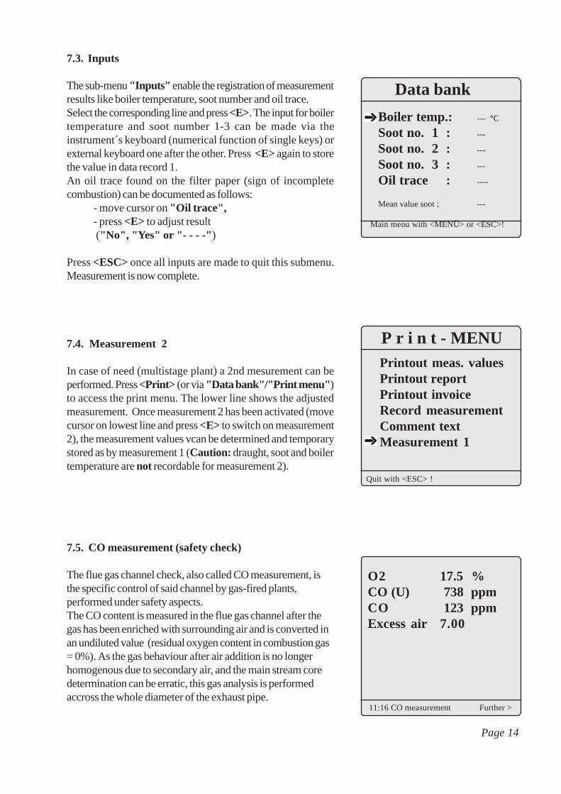
7.3. Inputs
The sub-menu "Inputs" enable the registration of measurementresults like boiler temperature, soot number and oil trace.Select the corresponding line and press <E>. The input for boilertemperature and soot number 1-3 can be made via theinstrument´s keyboard (numerical function of single keys) orexternal keyboard one after the other. Press <E> again to storethe value in data record 1.An oil trace found on the filter paper (sign of incompletecombustion) can be documented as follows:
- move cursor on "Oil trace",- press <E> to adjust result ("No", "Yes" or "- - - -" )
Press <ESC> once all inputs are made to quit this submenu.Measurement is now complete.
7.4. Measurement 2
In case of need (multistage plant) a 2nd mesurement can beperformed. Press <Print> (or via "Data bank"/"Print menu" )to access the print menu. The lower line shows the adjustedmeasurement. Once measurement 2 has been activated (movecursor on lowest line and press <E> to switch on measurement2), the measurement values vcan be determined and temporarystored as by measurement 1 (Caution: draught, soot and boilertemperature are not recordable for measurement 2).
7.5. CO measurement (safety check)
The flue gas channel check, also called CO measurement, isthe specific control of said channel by gas-fired plants,performed under safety aspects.The CO content is measured in the flue gas channel after thegas has been enriched with surrounding air and is converted inan undiluted value (residual oxygen content in combustion gas= 0%). As the gas behaviour after air addition is no longerhomogenous due to secondary air, and the main stream coredetermination can be erratic, this gas analysis is performedaccross the whole diameter of the exhaust pipe.
O2 17.5 %CO (U) 738 ppmCO 123 ppmExcess air 7.00
11:16 CO measurement Further >
Printout meas. valuesPrintout reportPrintout invoiceRecord measurementComment textMeasurement 1
P r i n t - MENU
Quit with <ESC> !
Page 14
Data bank
Boiler temp.: --- °C
Soot no. 1 : ---
Soot no. 2 : ---
Soot no. 3 : ---
Oil trace : ----
Mean value soot : ---
Main menu with <MENÜ> or <ESC>!

O2 17.5 %CO (U) 738 ppmCO 123 ppmExcess air 7.00
11:16 CO measurement Further >
MA multi-hole probe (optional accessory) is the ideal samplingtool hereto. The calculated CO value shown by “CO 0.0%”corresponds to the measured CO content, supposing that inthe same gas volume the 02 content is 0%. This isconsequently the undiluted CO content in the flue gas. Oncethe measured value is stable, press < m > in order to transferthe value in temporary storage.
7.6. Store measurement on RAM card
Once the gas analysis is completed, the determined values storedin the temporary memory can be correlated to the customer(storage on RAM card).Press <Print> (or via "Data bank"/"Print menu" ) to accessthe print menu.Select "Record measurement" and press <E>. The storedvalues are displayed.If you need to check customer address, measurement 1 andmeasurement 2, call these data up with the arrow keys. Press<m> (instrument´s keyboard) to correlate the results to thecustomer (storage on RAM card). By successful storage "M"is displayed on the upper right corner of the display.Press <ESC> to turn back to "Print menu" .Important: Only data stored on a RAM card can betransferred to the Voksy® programme!
8. Printout
The "Print menu" enables the following printouts (select lineand press <E>):
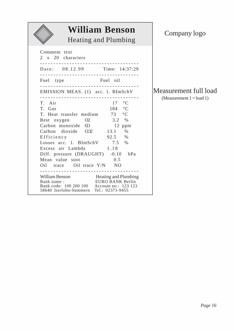
- Measurement values (see page 16):only the measurement values of the measurementselected in the print menu (with comment text2 x 20 characters, if stored under "Comment text" )will be printed
- Report (see page 17):complete service report with measurement 1 + 2(if stored) will be printed
- Invoice (see page 18):complete invoice with all inputed positions willbe printed
Meas. val. storageChange name!
1000001Dr. Alfred Anderson33 Main Street40000 DüsseldorfHouse wash laundry
M
Printout meas. valuesPrintout reportPrintout invoiceRecord measurementComment textMeasurement 1
P r i n t - MENU
Quit with <ESC> !
Page 15
William BensonHeating and Plumbing
Comment text2 x 20 characters- - - - - - - - - - - - - - - - - - - - - - - - - - - - - - - - - - - - -D a t e : 0 8 . 1 2 . 9 9 Time: 14:37:29- - - - - - - - - - - - - - - - - - - - - - - - - - - - - - - - - - - - -Fuel type Fuel oil- - - - - - - - - - - - - - - - - - - - - - - - - - - - - - - - - - - - -EMISSION MEAS. (1) acc. 1. BImSchV- - - - - - - - - - - - - - - - - - - - - - - - - - - - - - - - - - - - -T. Air 17 °CT. Gas 184 °CT. Heat transfer medium 73 °CRest oxygen O2 3.2 %Carbon monoxide CO 12 ppmCarbon dioxide CO2 13.1 %E f f i c i e n c y 92.5 %Losses acc. 1. BImSchV 7.5 %Excess air Lambda 1 . 1 8Diff. pressure (DRAUGHT) -0.10 hPaMean value soot 0.5Oil trace Oil trace Y/N NO- - - - - - - - - - - - - - - - - - - - - - - - - - - - - - - - - - - - -William Benson Heating and PlumbingBank name : EURO BANK BerlinBank code: 100 200 100 Account no.: 123 12358640 Iserlohn-Sümmern Tel.: 02371-9455
Company logo
Measurement full load(Measurement 1 = load 1)
Page 16

William BensonHeating and Plumbing
Bank data : EURO BANK BerlinBank code 100 300 100 Account no.: 123 12358640 Iserlohn-Sümmern Tel.: 02371-9455
08.03.00 FLUE GAS ANALYSIS 14:37 Full load Fuel type: Fuel oil
Combustion air temp. in sucking area 17°CHeat trasnfer medium temp. during analysis 73°CFlue gas temp. meas. in stream core 184°COxygen content (O2) in stream core 3.2% Vol.Carbone dioxide content (CO2) calculated out of O2 & CO2max 13.1 %Vol.Carbone monoxide (CO) parts per million 12 ppmExcess air calculated out of O2 & CO2max 1.18 LambdaPressure diff. (Location -> Exhaust system) -0.10 hPaAverage soot dot out of 3 meas. 0.5 scaleOil trace test Oil trace Yes/No NoEfficiency calculated (ETA) 92.5 %
Flue gas losses acc. to 1. BImSchV 7.5 %
Qty SERVICE JOB Qty SERVICE JOB 1 Nozzle 0.5-30 Gal/h 1 OV Siku filter element 1 Sealing ring oil filter OV 60 Min. service engineer 10 Kilometre service car
Customer no.: 1000001
Dr. Alfred Anderson33 Main Street40000 DüsseldorfStand: House wash laundry
SERVICE REPORT
Company address
Plant descriptionwith
adjustment data
Service job
Customer address
Report no. 1234567 of 08.12.99Document issued at 14:33 with flue gas analyser rbr-ecom FN Nr. 47/349
Order/Customer report:Check plant on trouble
Trouble constated....:Nozzle and filter soiled
Job made.............:Nozzle and filter changed
Service engineer.....:Frank Jones
Boiler.......: Buderus G 215 1998Burner.......: Weishaupt WL 20 Z 1998kW boiler....: 44 kW load: 40Oper. stand: Full load Oil pres.: 20.0 bar Nozzle: 1,00/60H Perfor.: 3,6 kg/hOper. stand: Partial load Oil pres.:12.0 bar Nozzle: 1,00/60H Perfor.: 2,8 kg/h
08.03.00 FLUE GAS ANALYSIS 14:38 Partial load Fuel type: Fuel oil
Combustion air temp. measured in sucking area 18 °CFlue gas temp. in stream core 166°COxygen content (O2)in stream core 4.0 % Vol.Carbone dioxide (CO2) out of O2/CO2max 12.5% Vol.Carbone monoxide (CO) parts per million 30 ppmExcess air calc. of O2 & CO2max 1.23 LambdaPress. diff.(Location -> Exhaust system) -0.10 hPaEfficiency calculated (ETA) 93.0 %Flue gas losses acc. to 1. BImSchV 7.0 %
Burner exchange recommended
Company logo
Measurement full load(Measurement 1 = load 1)
Measurement partialload
(Measurement 2 = load 2)
Page 17

William BensonHeating and Plumbing
Bank name: EUROPA BANK BerlinBank code: 100 200 100 Account no.: 123 123
58640 Iserlohn-Sümmern Tel.: 02371-9455
Qty Material and labour Price/pce Total price
1 Nozzle 0.5-30 Gal/h 23.00 DM 23.00 DM 1 OV Siku filter element 10.70 DM 10.70 DM 1 Sealing ring oil filter OV 2.14 DM 2.14 DM 60 Min. service engineer 1.50 DM 90.50 DM 10 Kilometre service car 0.89 DM 8.90 DM
net: 134.74 DM + 16% VAT.: 21.56 DM
Total invoice amount: 156.30 DM
Payment: Bank chargingBank charging accepted for invoice amount.Your account: 123 456 7890 BLZ: 200 100 00Bank charging will be processed with a 2% discount.
Come and visit our sanitary show with the last novelties!
Customer signature: _______________________________
Customer number: 1000001
Dr. Albert Anderson33 Main Street40000 DüsseldorfStand: House wash laundry
I N V O I C E
Company address
Invoice address
Report nr. 1234567 of 08.03.00Document issue 14:33 with flue gas analyser rbr-ecom FN Nr. 47/349
Order/Customer report: Check plant on trouble
Trouble constated........: Nozzle and filter soiled
Job made........................: Nozzle and filter changed
Service engineer............: Frank Jones
Boiler......: Buderus G 215 1998Burner........:Weishaupt WL 20 Z 1998
Company logo
Invoice
Job report
Payment mode
Page 18

9. Adjustments
Additionally to the described functions of the rbr-ecom FN,several adjustments can be made in the instrument. Select thesub-menu "Adjustments" and confirm with <E>. You will geta selection list of alterable parameters, which are to be adjustedaccording to the application. Move the cursor on the desired lineand call up or modify the adjustment with <E>.Selection list:
Unit (adjustment upon <E>):- Calculation of gas concentration in:
-ppm = volume concentration (parts per million)-mg/m3= mass concentration per volume unit-mg/kWh= mass concentration per performance unit
Undiluted (adjustment upon <E>):- Convertion of gas concentration into inputed rest oxygen (adjustment upon "YES" ):
-Formula for convertion:
Reference O2 (input after pressing <E>):- Input of residual oxygen content O
2rel
Air pressure (press <E> then input):- Input of barometric air pressure for the dew point calculation
Fuel type (press <E> then select):- Modification of adjusted fuel type (e.g. by mesurements at combi-plants)
Set clock (press <E> then input):- Correction of internal clock
Paper feed (press <E>):- Paper feed, one line
Menu INTERNAL (open menu with <E>):- Further instrument´s adjustments (see next chapter)
Erel = Emeas *21 - O2rel
21 - O2mea
Page 19
Unit ppmUndiluted NORef. O2 0.0 %Air pressure 1013 mbarFuel typeSet clockPaper clockMenu INTERNAL
Main menu with <Menü> or <ESC>
Adjustments

10. Menu INTERNAL
Printout contraste (0..9) (press <E> then input):- Contraste adjustment of printer
Key beep (adjust with <E>):- Acoustical signal by key pressing
VAT (press <E> then input):- Modification of VAT rate for calculation of total amount
Invoice number (press <E> then input):- Adjustment of start invoice number- Using the Voksy® Maintenance Management Programme the start of invoice number of the software and of the FN in order not to overlap. Example: In Voksy® the start invoice number is 10000, in the FN the start invoice number is 1. The FN canconsequently print out 9999 invoices and transferto Voksy® , before invoice number overlap.
Baud rate (adjustment upon <E>):- Adjustment of transfer rate by data transfer via RS 232:
- Use of lite Voksy® software: 9600 Baud, RTS/CTS activated
- Use of full Voksy® software: 115200 Baud, RTS/CTS activated
RAM card 1 (adjustment upon <E>):- Adjustment of total capacity RAM card 1 (slot 1)- By using a RAM card, the latest must be divided in 2 fields:
- Customer data (press <E> and then input): Example adjustment 448 kB (512 kB RAM card) 1 customer ~ 1,5 kB; 448 kB ~ 300 customers- Item data (automatic): Adjustment depending on the number of customers Example adjustment 64 kB (512 kB RAM card) 1 item ~ 0,05 kB; 64 kB ~ 1280 items
Input :
448 KByte
Quit with <ESC> !
Customer dataThe maximal volume amounts 16384 kByteby a 16 MB RAM card. The rbr- ecom-FNfits the volume consequently!
Print contraste (0..9) 5Key beep NOVAT : 16.0 %Invoice no. 001Baud rate 9600 BaudRAM card 1 4096 kBCustomer data 4032 kBItem data 64 kBRAM card 2 4096 kBType SRAM card
Main menu with <Menü> or <ESC>
Menu INTERNAL
Page 20

View back side ofRAM card
Write protect
SRAM card
Special case 2nd RAM card(Use only after consultation with you rbr-ecom dealer/subsidiary!)
Using 2 RAM cards select the adjustment customersdata = total capacity RAM card 1!
RAM card 2 (adjustment upon <E>):- Adjustment of total capacity RAM card 2 (slot 2)- Using 2 RAM cards, RAM card 1 will be used forcustomers data recording only.The item data bank (selection tables and catalogues)will be recorded on RAM card 2.
Type (adjustment upon <E>):- Selection of RAM card type for RAM card 2:
-SRAM card-Flash card-not used (always adjust, if no 2nd RAM card is used).
Important:Using SRAM cards, the write protection should not stand on"Write Protect", otherwise no data record is possible on theRAM card!
11. Menu Control
The electrochemical sensors for gas analysis wear out along thetime and age. They modify their output values during the courseof their use, depending on the gas concentration, the flow durationwith sampled gas and the gas purity.The programme controls the sensors and corrects drifts. If thesedrifts and the correlated measurement error is too high, so anerror message is then displayed. In this case, the correspondingsensor must be exchanged by an authorised service center.The control menu displays the current state values of the sensorsand additionally:
- the battery voltage (loading state),- the operation hours since the initial operation,- the serial number,- the telephone number of the next service center,- the day of initial use.
CONTROLO2 1005 mVoltCO 2 mVoltNO -1 mVoltZug -34 mVoltBatt 12.34 Volt
Operation hours : 25.11 hrsSerial number : FN 1Service tel. no. : 02371/945-5Initialisation : 13.12.99
Page 21

12. Data transfer
Only use an RS 232 connection cable provided by rbr-Compurtertechnik GmbH for data transfer(9-pin; 1 to 1 occupied).
12.1. Initialisation for Voksy® software
Prior to data transfer start Voksy® software/rbr-ecom FN, initialise the FN for this application.Proceeed as follows:- store the item catalogues to be transmitted first in the Voksy® software (see Voksy® software manual),- copy the directory "FNKATALG" from the diskette (Laufwerk A:\FNKATALG) on your fixed-disk (C:\FNKATALG)- switch into "DOS mode" (MS-DOS input)- call up the directorty C:\FNKATALG on (cd FNKATALG ; Return)- call up the programme thru input of "Start" and pressing "Return",- select the first menu point "Edit spares catalogues" and confirm with "Return"- assign the catalogue description you inputed in the Voksy® software the corresponding catalogue (activate the line "Catalogue description" with "Return"; make input; quit input with "Return"; answer question with "Y")- quit the editing mode with "F10" after all inputs have been made,- create a new transfer file (select menu point "Create new transfer file for rbr-ecom FN" and activate with "Return"),- check the inputs made (select menu point "View transfer file for rbr-ecom FN" and activate with "Return"),- transfer the file via COM1 or COM2 (select corresponding menu point and activate with "Return"; follow display instructions),- quit the programme after completed transfer (select menu point "Quit programme" and activate with "Return")
12.2. Conditions for data transfer
The following points must be observed to guarantee a frictionless data transfer between the rbr-ecom FN andthe Voksy® software:
- the FN must be initialised for the Voksy® software,- date and date must be correctly adjusted on both PC and FN,- the RAM cards adjustments must be made correctly (see § "Menu INTERNAL" ),- the interface adjustment in Voksy® and FN must match:
- use of Voksy® software: 115200 Baud, RTS/CTS activated.
Page 22

13. Menu Communication
This menu covers functions for data transfer and data care.According to the application, only some functions will beusable or worth to be used:
No use of Voksy® softwarePlease use only the function "Modify item data bank" .
Use of Voksy® softwarePlease use only the functions "Load customers data","Send customers data" and "Load item data bank" fordata transfer.Please pay attention to delete all customers data or item datastored in the rbr-ecom FN before loading customers/itemsdata from the Voksy® software (answer question with"YES" ).
Use of Voksy® software with RAM card reader modulePlease use only the function "Simulation RAM cardreader" for data transfer.
13.1. Deleting functions
- Delete customers dataAll stored customers and corresponding measurement results(service reports) will be deleted.- Delete item dataAll selection tables and catalogues will be deleted.- Delete all All data will be deleted on the RAM card.
Caution!Press these functions only if you´re sure that thecorresponding data should be deleted from the RAM card!
13.2. Modem transfer
An analogue Modem can be monitored by the rbr-ecom FNin order to realise a data remote transfer (DRT).After initialisation of the Modem (follow manufacturerinstructions) and input of selection command (depending ontelephone system), the transfer can take place via the menupoint "Start" . As an especially tailored receiving programmeis required for use, please consult in case of interest your rbr-ecom dealer/subsidiary.
CommunicationLoad customer dataSend customer dataLoad item data bankModify item data bankDelete cuustomer dataDelete item dataDelete allModem transferSimulation RAM card reader
rbr-ecom FN
Are you sure ?
YESNO
Delete customer data
Received : 0Sent : 0Ignored : 0DRT trouble : 0
PC direct connection
Quit with <ESC>!
Waiting for next command!
Page 23
Function "SimulationRAM card reader"
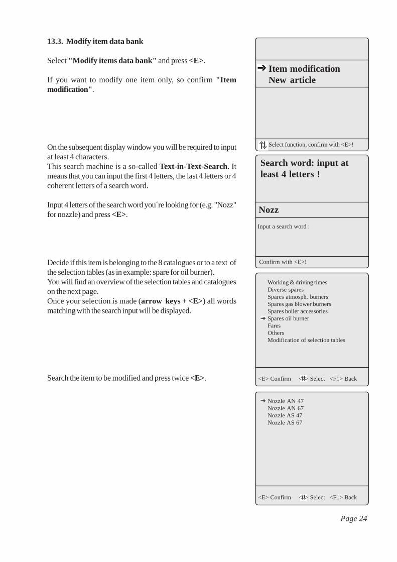
13.3. Modify item data bank
Select "Modify items data bank" and press <E>.
If you want to modify one item only, so confirm "Itemmodification" .
On the subsequent display window you will be required to inputat least 4 characters.This search machine is a so-called Text-in-Text-Search. Itmeans that you can input the first 4 letters, the last 4 letters or 4coherent letters of a search word.
Input 4 letters of the search word you´re looking for (e.g. "Nozz"for nozzle) and press <E>.
Decide if this item is belonging to the 8 catalogues or to a text ofthe selection tables (as in example: spare for oil burner).You will find an overview of the selection tables and catalogueson the next page.Once your selection is made (arrow keys + <E>) all wordsmatching with the search input will be displayed.
Search the item to be modified and press twice <E>.
Item modificationNew article
Select function, confirm with <E>!
Confirm with <E>!
Search word: input atleast 4 letters !
Input a search word :
Nozz
Working & driving timesDiverse sparesSpares atmosph. burnersSpares gas blower burnersSpares boiler accessoriesSpares oil burnerFaresOthersModification of selection tables
<E> Confirm < > Select <F1> Back
Nozzle AN 47Nozzle AN 67Nozzle AS 47Nozzle AS 67
<E> Confirm < > Select <F1> Back
Page 24

The following window is displayed.
You can now modify the item text or the price.
To store a new item, move the cursor in the menu point "Modifyitem data bank" on "New item" .Press <E> to access the input mask. Input the desired text, theprice and the catalogue group respectively selection table.Press 3 times <ESC> to turn back to the main menu.
Please observe!By new record or modification of an item, it is most important toinput respectively to keep the correct description of the catalogueor the selection table.Only if the correct description is made for the item to modify orto store as new, it is ascertained, that the required input is madein the corresponding selection table.By searching for the catalogue, please care for capital or smallletters.
Selection tables
Group Description
001 ZIP code/City002 Location003 Boiler manufacturer004 Manufacturing year005 Burner manufacturer006 Boiler type007 Burner type008 CDP works009 Measurement on load010 Oil burner nozzle050 Trouble message051 Trouble identification052 Troubleshooting053 Remark text for service report054 Remark text for invoice055 Service engineer056 Orderer057 Payment
Description. Nozzle AN 47Price (Pf) 008570Catalog. K KEÖ---------------e.g. 20 DMInputin Pf :002000
<ESC> End <PgUp/PgDn> select <F1>Back
Catalogues
Group Description
KAR Working & driving timesKED Diverse sparesKEK Spare boiler accessoriesKEA Spares atmosph. burnerKEG Spare gas blower burnerKEÖ Spare oil burnerKPA FaresKSO Others
Page 25

Selection Catalogue21220 Amelinghausen 00121250 Dohren 00121320 Eckel 00121334 Hausbruch 00121350 Nenndorf 00121440 Reindorf 00121650 Seevetal 00121770 Wulfsen 001acc. to invoice address 002Cellar 002House wash laundry 002Ground floor 002Brötje 003Buderus 003Dietrich 003Domotherm 003Ferroli 003Fröling 003Hoval 003PaKü 003Schäfer 003Strebel 003Vaillant 003Viessmann 003Weishaupt 003Wolf 0031984 0041985 0041986 0041987 0041988 0041989 0041990 0041991 0041992 0041993 0041994 0041995 0041996 0041997 0041998 004Brötje 005Buderus 005E-Klöckner 005Elect.-Oil 005Giersch 005Hansa 005Hofamat 005Hoval 005Körting 005MAN 005OERTLI-Ro. 005Olymp 005Riello 005Thyssen 005Weishaupt 005G105 006G115 006G205 006Typ Hoval 006KL 20 007RE 1.0 007RE 1.0 LN 007Typ Hoval 007WL 10 007WL 20 007BH+KR 008BH+KR+T 008BI 008BI+KR 008BI+KR+T 008BK 008BK+T 0081st. step 009
Selection Catalogue2nd. step 009Partial load 009Full lioad 0090,40/45S 0100,40/60E 0100,40/60H 0100,40/60S 0100,40/80H 0100,50/45S 0100,50/60E 0100,50/60H 0100,50/60S 0100,50/80H 0100,50-45 0100,60/45S 0100,60/60E 0100,60/60H 0100,60/60S 0100,60/80H 0100,65/60E 0100,65/60H 0100,65/80H 0100,75/45S 0100,75/60H 0100,75/60S 0100,75/80H 0100,85/45S 0100,85/60H 0100,85/60S 0100,85/80H 0101,00/45S 0101,00/60H 0101,00/60S 0101,00/80H 0101,10/60H 0101,10/80H 0101,25/45S 0101,25/60H 0101,25/60S 0101,25/80H 0101,50/45S 0101,50/60S 010Plant disturbed 050Plant off (no further info) 050Automatic is out of order 050Burner disturbed 050Burner buffers 050Noise coming up 050Heating and water don´t warm up 050Heating doesn´t warm up 050Initiation 050Heating fuse fails down 050Tank emptied 050Circulation pump defect 050Maintenance 050Water doesn´t warm up 050Automatic defect 051Automatic misadjusted 051Burner defect 051Burner doesn´t ignate 051Nozzle and filter soiled 051Nozzle soiled 051Filter soiled 051Main switch off 051Air in the plant 051Not enough fuel oil 051Circulation pump defect 051Burner main revision 052Burner control check 052Boiler cleaning 052Boiler cleaning (chemical) 052Boiler / exhaust pipe tightened 052Burner checked, defect parts exchanged 052Burner verified 052
14. Selection tables
Page 26

Selection Catalogue
New oil burner installed and adjusted 052Draught regulator installed 052Circulation pump exchanged 052Quick exhauster exchanged 052Extension container exchanged 052KFE cock exchanged 052Automatic adjusted 052Automatic repaired 052Burner inspection 052Burner retrofitted on lower performance 052Boiler sucks secondary air 053Burners has (further) defects 053Burner exchange recommended 053Automatic is defect 053Exhaust pipe defect, exchange necessary 053Chimney draught too high 053Installation of draught regulator recommended 053Warranty period is over 053Oil supply is not OK 053Installation of one -line system recommended 053Tank cleaning recommended 053Please call regarding order submission 053Plant switched off because of danger 053Boiler cleaning necessary 053Labour and driving acc. to maintenance contract 054Works under warranty 054No charging due to good will 054Warranty period is over 054Trouble source due to handling 054Plant has (further) defects 054By question reg. the invoice please call 054Plant switched off because of danger 054Service contract recommended 054Payment with cheque no. 054Frank Allison 055Jim Smith 055Harry Windslow 055William Sotheby 056Miss 056Mister 056Tenant 056see receiver 056Until: 057In 2 rates 057Received in cash! 057Within 14 days! 057Cheque payment 057AZE Working-day normal time 002220KARAZE Overtime before 8.00 pm 002400KARAZE Overtime after 8.00 pm 002600KARAZE Overtime Sunday 002800KARAZE Overtime public holiday 003050KARFZE Working-day normal time 001820KARFZE Overtime before 8.00 pm 002000KARFZE Overtime after 8.00 pm 002200KARFZE Overtime Sunday 002400KARFZE Overtime public holiday 002650KAROil-level gauge 001850KEDOne-line system oil filter 004100KEDTwo-line system oil filter 003030KEDFilter element Siku 000195KEDFilter element Niro 000425KEDFilter element Filz 000190KEDQuick-acting gate valve 8mm 002210KEDQuick-acting gate valve 10mm 002440KEDQuick-acting gate valve 12mm 002870KEDFoot valve 3/8" 000880KEDFoot valve 1/2" 000990KEDGland screw 1"x8/10 001040KEDVentilation cap 1 1/2" 001220KEDFilling tube cap 2" 001620KEDLimit transmitter 003225KEDFlexo block 1 1/2" 009720KEDLift protection valve 009850KEDLeak detector spray 001060KEDBurner cleaner 000790KEDChimney draught controller 003675KED
Selection Catalogue
Manometer 0-4 bar 001185KEKManometer shut-off valve 000270KEKSafety valve 2,5 bar 001340KEKSafety valve 10 bar 001340KEKThermometer 63 mm 001530KEKQuick-exhauster 000870KEKStop valve 000140KEKControl thermostat 009000KEKSafety temp. limiter 008500KEKThermoelement TE-600 000715KEAThermoelement 001950KEACombi-valve V 4600 016720KEACombi-valve V 4400 022800KEACombi-valve V 4610 017630KEACombi-valve V 4635 028240KEAPiezo ignitor 003610KEAGas filter 1/2 „ 007000KEAGas filter 3/4 „ 007100KEAGas filter 1 „ 011000KEAGas pressure controller 1/2 „ 009600KEAGas pressure controller 3/4 „ 009600KEAGas pressure controller 1 „ 011700KEAGas pressure watcher 008730KEAGas switch valve 1/2 „ 000740KEAGas switch valve 3/4 „ 001070KEAGas switch valve 1 „ 001530KEAGas counter conn. plate 1" 003660KEASurface burner KEAGas meter 1 „ 045700KEAGas pressure controller 1 „ 025000KEAManometer 1/2" 010800KEAPush-button gauge-cock 1/2" 003400KEAFlue gas temperature sensor KEASAT. firing automaton MMI 020930KEGSAT. firing automaton MMG 025970KEGLight sensor UVZ 780 013830KEGIonisation electrode 001130KEGL & G automation LFM 032200KEGLight sensor UV RAZ 015200KEGUnivers. ignition trafo 008260KEGIgnition electrodes 000450KEGAir pressure controller KEGGas pressure controller KEGGas electrovalve 1/2 „ KEGGas electrovalve 3/4 „ KEGOil nozzle exchanged 001800KEÖflex. oil hose 1000 mm 001200KEÖOil preheater 010300KEÖOil pump AN 47 008570KEÖOil pump AN 67 009830KEÖOil pump AS 47 010250KEÖOil pump AS 67 012650KEÖEckerle pump 013500KEÖCover seal 000140KEÖPump sifter 000410KEÖL & G automaton LOA 21 006150KEÖL & G automaton LOA 25 011100KEÖLight sensor QRB 001600KEÖDANFOSS automaton BHO 62 006900KEÖDANFOSS automaton BHO 64 013100KEÖSATRONIK automaton TF 801 005450KEÖSATRONIK automaton TF 804 006010KEÖUnivers. ignition trafo 008260KEÖIgnition electrodes 000450KEÖDouble electrode 000650KEÖElectrovalve 1/4 „ 003430KEÖJourney rate 001000KPAEmission measurement 002500KPAInitiation oil burner 020000KPAInitiation gas burner 018000KPAInitiation gas boiler 016000KPASmall material 000500KPAMaintenance oil burner 022000KPAMaintenance gas burner 020000KPAMaintenance gas boiler 018000KPACash payment discount - 500KSOCash payment discount - 1000KSO
Page 27

15. Maintenance advices
We recommend to have your instrument serviced by anauthorised and qualified service center one time a year respectivelyafter 500 operation hours at a maximum in order to check andclean sensors and inner hoses.Do not use any part not provided by us and consider that serviceworks done by other service centers than those appointed by uscancel any warranty.The following advices for the daily maintenance of single partsand sub-assemblies may be of help:
The instrument is fitted with filters for the protection of the sensorsand gas-leadings parts which need a regular check. These are:
Fine dust filter on the gas coolerUnscrew the lid of the gas cooler and check the particle filter. Itshould be changed when the filter is dark grey/black where thegas comes in (soot number approx. 2-3).
C) SO2/NOx filterIn the tubing leading to the CO sensor on the rear of theinstrument, there is a chemical filter for filtering SO2 and NOxout of the flue gas. The filter material is manganese VII oxidegranules and should be changed once it has turned grey (colourchange : pink > brown > black > grey > white).
SensorsAfter switching on the instrument, the sensors are calibrated withfresh air. The instrument constantly checks the sensor status.New sensors age due to the reagents being used up (oxygensensor) or due to dirt or being exposed to concentrations abovetheir standard range (toxic gas sensors). The initial values forsensors in check mode are :
Oxygen sensor approx. 1000 mVCO sensor 0 mV (+/- 70)NO sensor 0 mV (+/- 30)
These values are relative values created by the instrument´sprogramme. The check mode <CTRL> for the toxic gas sensorsshould show a value < +/- 150 mV. If not, the calibration shouldbe repeated. If an error occurs during calibration and does notdisappear after repeating the calibration several times, theinstrument should be sent in for servicing.
Fine dust filter
Page 28

The oxygen sensor should show a value > 200 mV. If this is notthe case, it should be exchanged.
The sensors have a programmed limit value which exceedingreleases a magnet valve leading fresh air to the sensor(s). Thisvalue is 4000 ppm for the CO sensor, for other toxic cells (so farfitted) it corresponds to the measurement range end value.
Mains supplyRechargeable batteries are used for mains free operation. Thebatteries have a capacity of 1.2 Ah and the length of use dependson the operating mode. The batteries are recharged by pluggingthe instrument into the mains (charge time approx. 10 hours).Switching on is not necessary. The batteries should be rechargedonce the voltage display reads less than 11 V (the critical pointis 10.5 V after this the instrument will not function).
Probe and sampling hoseThe tubing and the probe should be cleaned regularly, dependingon use, thus in order to remove dirt and to avoid wear due tocorrosion taking place. The coaxial probe can be dismantled byunscrewing the outer tube. The inner tube is connected to thegrip. The thermocouple is permanently attached to the grip. Thetubing can be cleaned after removing it from the connections onthe instrument and probe (use warm water and then dry or blowdry).
Change paper roll
Release the box cover (press lock forwards) and pull out resi-dual paper from the printer ("Adjustements" /"Paper feed"/<E>). Extract the printer shaft and put the new roll on the shaft.Insert the paper roll end through the slot. Forward the paper(approx. 10 cm) through the printer ("Adjustments" /"Paperfeed"/<E>). Place the paper roll in the box (printer shaft in thedesigned guidance mechanism) and re-position the cover (leadpaper through the slot).
Lock Cover
Paper slot
Paper rollPrinter shaft
ê
Page 29
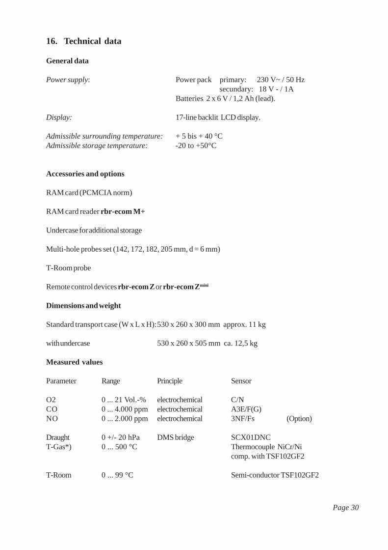
16. Technical data
General data
Power supply: Power pack primary: 230 V~ / 50 Hz secundary: 18 V - / 1A
Batteries 2 x 6 V / 1,2 Ah (lead).
Display: 17-line backlit LCD display.
Admissible surrounding temperature: + 5 bis + 40 °CAdmissible storage temperature: -20 to +50°C
Accessories and options
RAM card (PCMCIA norm)
RAM card reader rbr-ecom M+
Undercase for additional storage
Multi-hole probes set (142, 172, 182, 205 mm, d = 6 mm)
T-Room probe
Remote control devices rbr-ecom Z or rbr-ecom Zmini
Dimensions and weight
Standard transport case (W x L x H):530 x 260 x 300 mm approx. 11 kg
with undercase 530 x 260 x 505 mm ca. 12,5 kg
Measured values
Parameter Range Principle Sensor
O2 0 ... 21 Vol.-% electrochemical C/NCO 0 ... 4.000 ppm electrochemical A3E/F(G)NO 0 ... 2.000 ppm electrochemical 3NF/Fs (Option)
Draught 0 +/- 20 hPa DMS bridge SCX01DNCT-Gas*) 0 ... 500 °C Thermocouple NiCr/Ni
comp. with TSF102GF2
T-Room 0 ... 99 °C Semi-conductor TSF102GF2
Page 30

Calculated values
Parameter Calculation Resolution Formula
CO2
0 - CO2max
0,1 %
Losses 0 - 99,9 % 0,1 %
Efficiency 0 - 99,9 % 0,1 %
Excess air 1 - l 0,01
Fuel types acc. to 1. BImSchVCO2max. values and factors
Fuel type A1 A2 B CO2maxFuel oil (B) 0,50 0,68 0,007 15,4Natural gas (B) 0,37 0,66 0,009 11,8Town gas (B) 0,35 0,63 0,011 11,7Coke oven gas (B) 0,29 0,60 0,011 10,2Liquid gas (B) 0,42 0,63 0,008 14,0
Conversions and factors (ppm - mg/m3)
Gas ppm in mg/m3mg/m3 in ppm
O2 1,429 0,699CO 1,25 0,8NO 1,34 0,75NOx 2,05 0,49
=CO2 CO
2max* (1-O
2measured
21 )
qA
= + B * )( ( TGas
- TAir
)21 - O
2
A2
ETA = 100 - qA
= 1+O
2
21 - O2
λ
Page 31
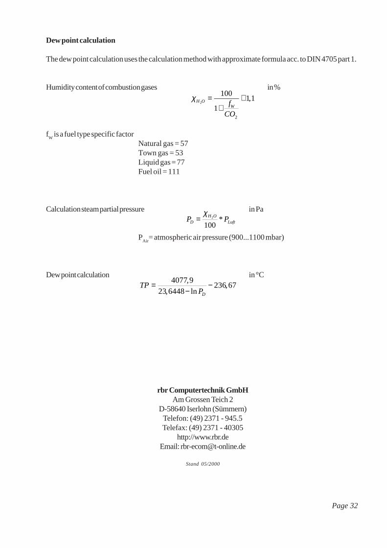
Dew point calculation
The dew point calculation uses the calculation method with approximate formula acc. to DIN 4705 part 1.
Humidity content of combustion gases in %
fW
is a fuel type specific factorNatural gas = 57Town gas = 53Liquid gas = 77Fuel oil = 111
Calculation steam partial pressure in Pa
PAir
= atmospheric air pressure (900...1100 mbar)
Dew point calculation in °C
χH OWf
CO
2
100
11 1
2
=+
+ ,
P PDH O
Luft=χ
2
100*
TPPD
=−
−4077 9
23 6448236 67
,
, ln,
rbr Computertechnik GmbHAm Grossen Teich 2
D-58640 Iserlohn (Sümmern)Telefon: (49) 2371 - 945.5Telefax: (49) 2371 - 40305
http://www.rbr.deEmail: [email protected]
Stand 05/2000
Page 32