Embed Size (px)
Citation preview

Operating Instructions
Page 2 ecom-DP3
Index Page 1. Application and components 3 2. Design ecom-DP3 5 3. Connection of components 7 4. Data processing
4.1. Data storage 8 4.2. Edit customer 8 4.3. Select customer 9 5. Control programs 5.1. Setup control programs 11 5.2. Natural gas 5.2.1. Stress test 14 5.2.2. Tightness check 15 5.2.3. Usability check 16 5.3. Liquid gas 5.3.1. Tightness check 18 5.3.2. Pressure test 19 5.3.3. Pressure test 0 – 40 bar 20 5.4. Drinking water (option)
5.4.1. Drinking water plant (wet) 5.4.1.1. Function test 21 5.4.1.2. Pressure test 22 5.4.1.3. Extended test 23
5.4.2. Drinking water plant (dry) 5.4.2.1. Tightness check 24 5.4.2.2. Stress test 25
5.5. Heating (option) 26 5.6. Sewage (option) 27 6. More measurements 6.1. Single measurement 28 6.2. Heating Check (option) 29 6.3. 4Pa measurement (option) 32 6.4. Pressure check 33 7. Adjustments 34 8. Control (system test) 36 9. Technical Data ecom-DP3 37 10. Maintenance tips 38
ecom-DP3 Page 3
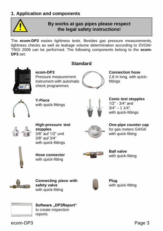
1. Application and components The ecom-DP3 easies tightness tests. Besides gas pressure measurements, tightness checks as well as leakage volume determination according to DVGW-TRGI 2008 can be performed. The following components belong to the ecom-DP3 set:
Standard
By works at gas pipes please respect
the legal safety instructions!
Hose connector with quick-fitting
ecom-DP3 Pressure measurement instrument with automatic check programmes
Connection hose 2,8 m long, with quick-fittings
High-pressure test stopples 3/8“ auf 1/2“ und 3/8“ auf 3/4“ with quick-fittings
One-pipe counter cap for gas meters G4/G6 with quick-fitting
Conic test stopples 1/2“ - 3/4“ and 3/4" – 1 1/4", with quick-fittings
Y-Piece with quick-fittings
Ball valve with quick-fitting
Connecting piece with safety valve with quick-fitting
Plug with quick-fitting
Software „DP3Report“ to create inspection reports
Page 4 ecom-DP3
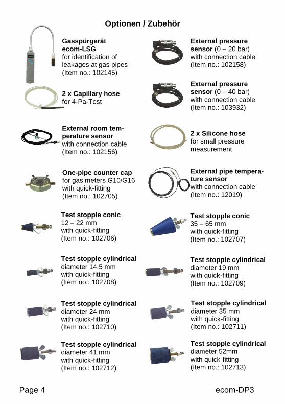
Optionen / Zubehör
Gasspürgerät ecom-LSG for identification of leakages at gas pipes (Item no.: 102145)
External pressure sensor (0 – 20 bar) with connection cable (Item no.: 102158)
2 x Capillary hose for 4-Pa-Test
2 x Silicone hose for small pressure measurement
External room tem-perature sensor with connection cable (Item no.: 102156)
External pipe tempera-ture sensor with connection cable (Item no.: 12019)
One-pipe counter cap for gas meters G10/G16 with quick-fitting (Item no.: 102705)
Test stopple conic 12 – 22 mm with quick-fitting (Item no.: 102706)
Test stopple cylindrical diameter 14,5 mm with quick-fitting (Item no.: 102708)
Test stopple cylindrical diameter 24 mm with quick-fitting (Item no.: 102710)
Test stopple cylindrical diameter 41 mm with quick-fitting (Item no.: 102712)
External pressure sensor (0 – 40 bar) with connection cable (Item no.: 103932)
Test stopple conic 35 – 65 mm with quick-fitting (Item no.: 102707)
Test stopple cylindrical diameter 19 mm with quick-fitting (Item no.: 102709)
Test stopple cylindrical diameter 35 mm with quick-fitting (Item no.: 102711)
Test stopple cylindrical diameter 52mm with quick-fitting (Item no.: 102713)
ecom-DP3 Page 5
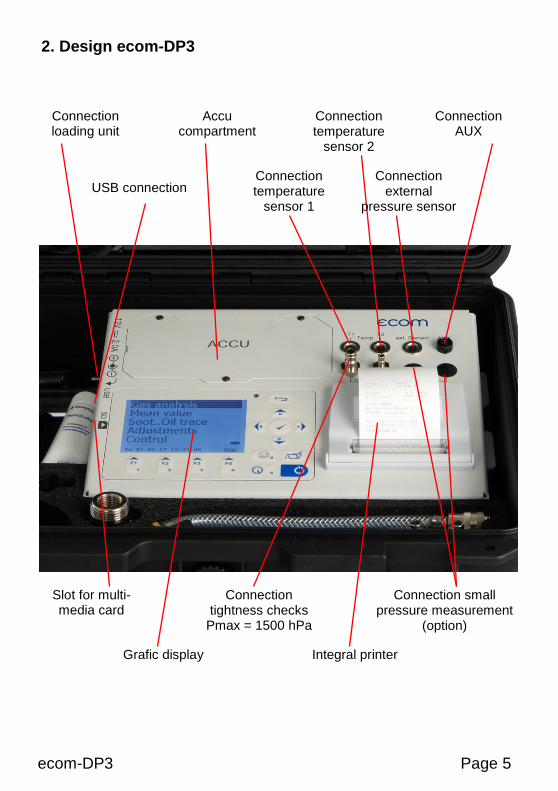
2. Design ecom-DP3
Connection tightness checks
Pmax = 1500 hPa
Connection small pressure measurement
(option) Pmax = 20 hPa
Connection loading unit
Grafic display Integral printer
Slot for multi-media card
USB connection
Accu compartment
Connection temperature
sensor 2
Connection external
pressure sensor
Connection AUX
Connection temperature
sensor 1

Page 6 ecom-DP3
Keyboard
ESC key (quit/
exit menu)
In the input mode, the keys are used for numerical inputs
Enter key (confirm
selection)
Cursor keys (Up/Down/Right/
Left/Scroll)
Values recording
Print key (access to
printing menu)
ON / OFF key
Info key (access to
control menu)
Function keys (function shown on
display)
ecom-DP3 Page 7
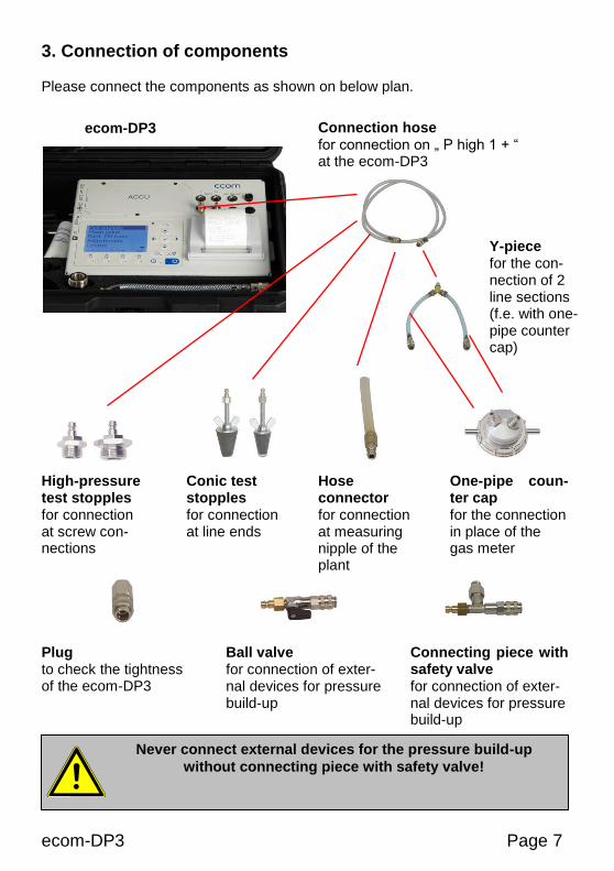
3. Connection of components Please connect the components as shown on below plan.
Connection hose for connection on „ P high 1 + “ at the ecom-DP3
ecom-DP3
Y-piece for the con-nection of 2 line sections (f.e. with one-pipe counter cap)
Hose connector for connection at measuring nipple of the plant
High-pressure test stopples for connection at screw con-nections
One-pipe coun-ter cap for the connection in place of the gas meter
Conic test stopples for connection at line ends
Ball valve for connection of exter-nal devices for pressure build-up
Connecting piece with safety valve for connection of exter-nal devices for pressure build-up
Plug to check the tightness of the ecom-DP3
Never connect external devices for the pressure build-up
without connecting piece with safety valve!
Page 8 ecom-DP3
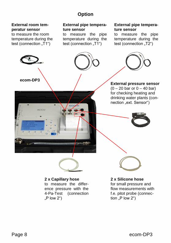
Option
External pressure sensor (0 – 20 bar or 0 – 40 bar) for checking heating and drinking water plants (con-nection „ext. Sensor“)
ecom-DP3
2 x Capillary hose to measure the differ-ence pressure with the 4-Pa-Test (connection „P low 2“)
2 x Silicone hose for small pressure and flow measurements with f.e. pitot probe (connec-tion „P low 2“)
External room tem-peratur sensor to measure the room temperature during the test (connection „T1“)
External pipe tempera-ture sensor to measure the pipe temperature during the test (connection „T1“)
External pipe tempera-ture sensor to measure the pipe temperature during the test (connection „T2“)
ecom-DP3 Page 9
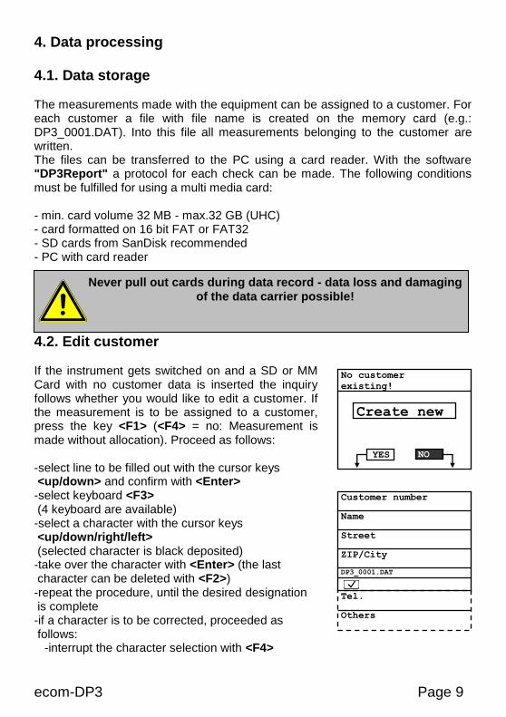
4. Data processing 4.1. Data storage
The measurements made with the equipment can be assigned to a customer. For each customer a file with file name is created on the memory card (e.g.: DP3_0001.DAT). Into this file all measurements belonging to the customer are written. The files can be transferred to the PC using a card reader. With the software "DP3Report" a protocol for each check can be made. The following conditions must be fulfilled for using a multi media card: - min. card volume 32 MB - max.32 GB (UHC) - card formatted on 16 bit FAT or FAT32 - SD cards from SanDisk recommended - PC with card reader
4.2. Edit customer
If the instrument gets switched on and a SD or MM Card with no customer data is inserted the inquiry follows whether you would like to edit a customer. If the measurement is to be assigned to a customer, press the key <F1> (<F4> = no: Measurement is made without allocation). Proceed as follows: -select line to be filled out with the cursor keys <up/down> and confirm with <Enter> -select keyboard <F3> (4 keyboard are available) -select a character with the cursor keys <up/down/right/left> (selected character is black deposited) -take over the character with <Enter> (the last character can be deleted with <F2>) -repeat the procedure, until the desired designation is complete -if a character is to be corrected, proceeded as follows:
-interrupt the character selection with <F4>
No customer
existing!
Create new
YES NO
Never pull out cards during data record - data loss and damaging
of the data carrier possible!
Customer number
Name
Street
ZIP/City
DP3_0001.DAT
Tel.
Others
Page 10 ecom-DP3
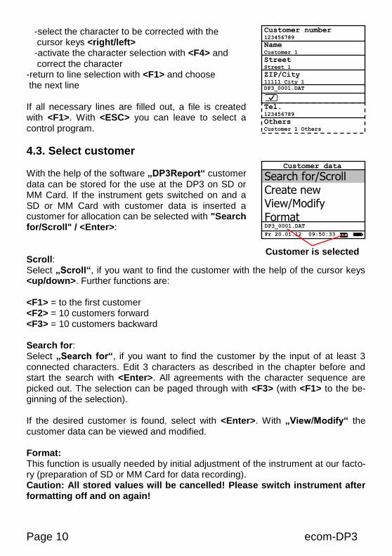
-select the character to be corrected with the cursor keys <right/left> -activate the character selection with <F4> and correct the character
-return to line selection with <F1> and choose the next line If all necessary lines are filled out, a file is created with <F1>. With <ESC> you can leave to select a control program.
4.3. Select customer
With the help of the software „DP3Report“ customer data can be stored for the use at the DP3 on SD or MM Card. If the instrument gets switched on and a SD or MM Card with customer data is inserted a customer for allocation can be selected with "Search for/Scroll" / <Enter>: Scroll: Select „Scroll“, if you want to find the customer with the help of the cursor keys <up/down>. Further functions are: <F1> = to the first customer <F2> = 10 customers forward <F3> = 10 customers backward Search for: Select „Search for“, if you want to find the customer by the input of at least 3 connected characters. Edit 3 characters as described in the chapter before and start the search with <Enter>. All agreements with the character sequence are picked out. The selection can be paged through with <F3> (with <F1> to the be-ginning of the selection). If the desired customer is found, select with <Enter>. With „View/Modify“ the customer data can be viewed and modified. Format: This function is usually needed by initial adjustment of the instrument at our facto-ry (preparation of SD or MM Card for data recording). Caution: All stored values will be cancelled! Please switch instrument after formatting off and on again!
Search for/Scroll Create new View/Modify
Format
Fr 20.01.12 09:50:33
Customer data
DP3_0001.DAT
Customer is selected
Customer number 123456789
Name Customer 1
Street Street 1
ZIP/City 11111 City 1
DP3_0001.DAT
Tel. 123456789
Others Customer 1 Others
ecom-DP3 Page 11
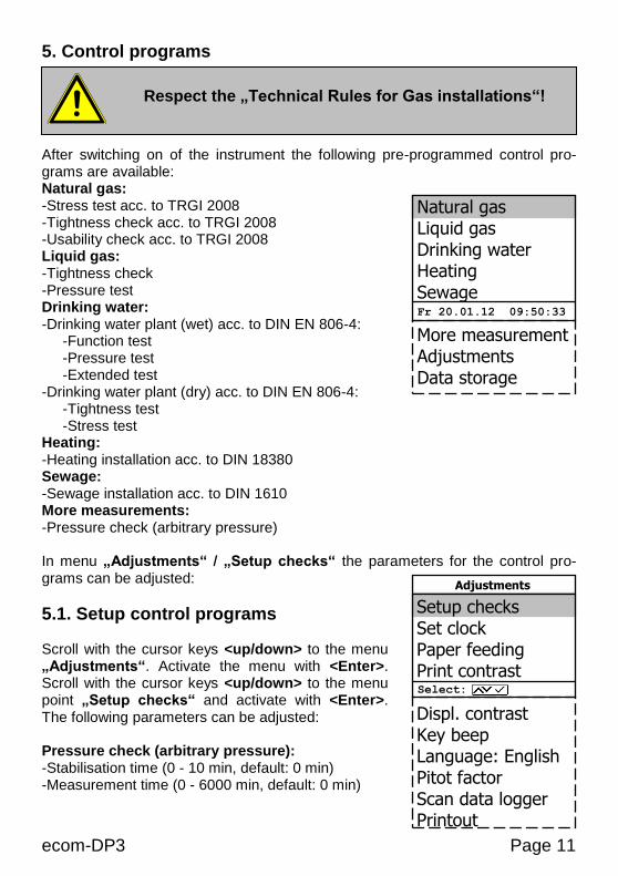
5. Control programs After switching on of the instrument the following pre-programmed control pro-grams are available: Natural gas: -Stress test acc. to TRGI 2008 -Tightness check acc. to TRGI 2008 -Usability check acc. to TRGI 2008 Liquid gas: -Tightness check -Pressure test Drinking water: -Drinking water plant (wet) acc. to DIN EN 806-4: -Function test -Pressure test -Extended test -Drinking water plant (dry) acc. to DIN EN 806-4: -Tightness test -Stress test Heating: -Heating installation acc. to DIN 18380 Sewage: -Sewage installation acc. to DIN 1610 More measurements: -Pressure check (arbitrary pressure) In menu „Adjustments“ / „Setup checks“ the parameters for the control pro-grams can be adjusted:
5.1. Setup control programs Scroll with the cursor keys <up/down> to the menu „Adjustments“. Activate the menu with <Enter>. Scroll with the cursor keys <up/down> to the menu point „Setup checks“ and activate with <Enter>. The following parameters can be adjusted: Pressure check (arbitrary pressure): -Stabilisation time (0 - 10 min, default: 0 min) -Measurement time (0 - 6000 min, default: 0 min)
Respect the „Technical Rules for Gas installations“!
Natural gas Liquid gas Drinking water Heating Sewage More measurement Adjustments Data storage
Fr 20.01.12 09:50:33
Setup checks Set clock Paper feeding Print contrast Displ. contrast Key beep Language: English Pitot factor Scan data logger Printout
Select:
Adjustments
Page 12 ecom-DP3
Stress test acc. to TRGI 2008: -Stabilisation time (1 - 10 min, default: 1 min) -Measurement time (10 - 120 min, default: 10 min) -Test pressure (900 - 1500 hPa, default: 1000 hPa) Tightness check acc. to TRGI 2008: -Stabilisation time installation lower 100 Liter (1 - 20 min, default: 10 min) -Measurement time installation lower 100 Liter (9 - 120 min, default: 10 min) -Stabilisation time installation 100 bis 200 Liter (20 - 40 min, default: 30 min) -Measurement time installation 100 bis 200 Liter (19 - 120 min, default: 20 min) -Stabilisation time installation higher 200 Liter (50 - 70 min, default: 60 min) -Measurement time installation higher 200 Liter (29 - 120 min, default: 30 min) -Test pressure (15 - 500 hPa, default: 150 hPa) Usability check acc. to TRGI 2008: -Stabilisation time (5 - 240 min, default: 10 min) -Measurement time (2 - 30 min, default: 5 min) -Reference pressure (10 - 100 hPa, default: 23 hPa) Function test drinking water plant (wet) acc. to DIN EN 806-4: -Stabilisation time (0 - 120 min, default: 30 min) -Measurement time (1 - 120 min, default: 15 min) -Test pressure (0.01 – 20.00 bar, default: 6.00 bar) Pressure test drinking water plant (wet) acc. to DIN EN 806-4: -Stabilisation time (0 - 120 min, default: 0 min) -Measurement time (1 - 120 min, default: 30 min) -Test pressure (0.01 – 20.00 bar, default: 11.00 bar) Extended test drinking water plant (wet) acc. to DIN EN 806-4: -Stabilisation time (0 - 120 min, default: 0 min) -Measurement time (1 - 240 min, default: 120 min) -Test pressure (0.01 – 20.00 bar, default: 5.50 bar) Tightness test drinking water plant (dry) acc. to DIN EN 806-4: -Stabilisation time (0 - 120 min, default: 0 min) -Measurement time (1 - 240 min, default: 120 min) -Test pressure (1 - 2000 hPa, default: 150 hPa) Stress test drinking water plant (dry) acc. to DIN EN 806-4: -Stabilisation time (0 - 120 min, default: 0 min) -Measurement time (1 - 120 min, default: 10 min) -Test pressure (0.01 – 5.00 bar, default: 1.00 bar) Heating plant acc. to DIN 18380: -Stabilisation time (0 - 120 min, default: 0 min) -Measurement time (1 - 240 min, default: 120 min) -Test pressure (0.01 – 20.00 bar, default: 10.00 bar) Sewage plant acc. to DIN 1610: -Stabilisation time (0 - 100 min, default: 0 min) -Measurement time (1 - 120 min, default: 30 min) -Test pressure (1 - 2000 hPa, default: 200 hPa)
ecom-DP3 Page 13
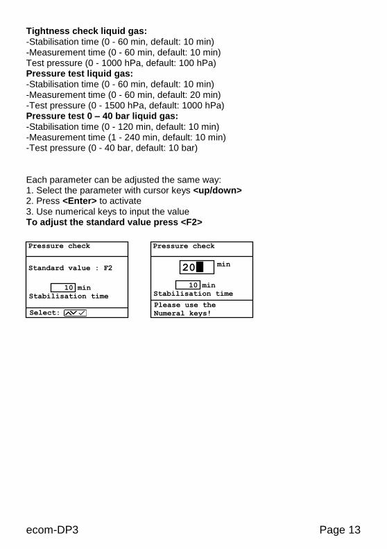
Tightness check liquid gas: -Stabilisation time (0 - 60 min, default: 10 min) -Measurement time (0 - 60 min, default: 10 min) Test pressure (0 - 1000 hPa, default: 100 hPa) Pressure test liquid gas: -Stabilisation time (0 - 60 min, default: 10 min) -Measurement time (0 - 60 min, default: 20 min) -Test pressure (0 - 1500 hPa, default: 1000 hPa) Pressure test 0 – 40 bar liquid gas: -Stabilisation time (0 - 120 min, default: 10 min) -Measurement time (1 - 240 min, default: 10 min) -Test pressure (0 - 40 bar, default: 10 bar) Each parameter can be adjusted the same way: 1. Select the parameter with cursor keys <up/down> 2. Press <Enter> to activate 3. Use numerical keys to input the value
To adjust the standard value press <F2>
Pressure check
min
10 min
Stabilisation time
Please use the
Numeral keys!
20
Pressure check
Standard value : F2
10 min
Stabilisation time
Select:
Page 14 ecom-DP3
5.2. Natural gas
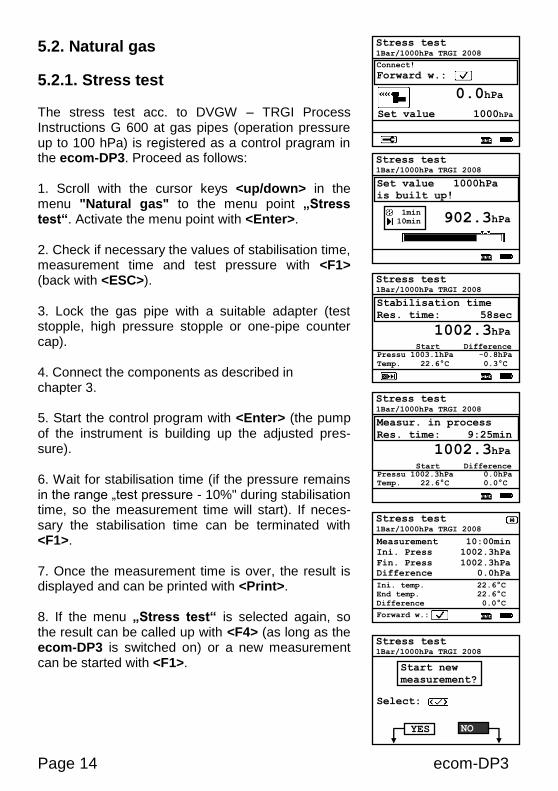
5.2.1. Stress test The stress test acc. to DVGW – TRGI Process Instructions G 600 at gas pipes (operation pressure up to 100 hPa) is registered as a control pragram in the ecom-DP3. Proceed as follows: 1. Scroll with the cursor keys <up/down> in the menu "Natural gas" to the menu point „Stress test“. Activate the menu point with <Enter>. 2. Check if necessary the values of stabilisation time, measurement time and test pressure with <F1> (back with <ESC>). 3. Lock the gas pipe with a suitable adapter (test stopple, high pressure stopple or one-pipe counter cap). 4. Connect the components as described in chapter 3. 5. Start the control program with <Enter> (the pump of the instrument is building up the adjusted pres-sure). 6. Wait for stabilisation time (if the pressure remains in the range „test pressure - 10%" during stabilisation time, so the measurement time will start). If neces-sary the stabilisation time can be terminated with <F1>. 7. Once the measurement time is over, the result is displayed and can be printed with <Print>. 8. If the menu „Stress test“ is selected again, so the result can be called up with <F4> (as long as the ecom-DP3 is switched on) or a new measurement can be started with <F1>.
Stress test 1Bar/1000hPa TRGI 2008
Stabilisation time
Res. time: 58sec
Pressu 1003.1hPa -0.8hPa
Temp. 22.6°C 0.3°C
Start Difference
1002.3hPa
Stress test 1Bar/1000hPa TRGI 2008
Measur. in process
Res. time: 9:25min
Pressu 1002.3hPa 0.0hPa
Temp. 22.6°C 0.0°C
Start Difference
1002.3hPa
Stress test 1Bar/1000hPa TRGI 2008
Set value 1000hPa
is built up!
902.3hPa 1min
10min
Stress test 1Bar/1000hPa TRGI 2008
Connect!
Forward w.:
Set value 1000hPa
0.0hPa
Stress test 1Bar/1000hPa TRGI 2008
Measurement 10:00min
Ini. Press 1002.3hPa
Fin. Press 1002.3hPa
Difference 0.0hPa Ini. temp. 22.6°C
End temp. 22.6°C
Difference 0.0°C
Forward w.:
Stress test 1Bar/1000hPa TRGI 2008
Start new
measurement?
Select:
YES NO
ecom-DP3 Page 15
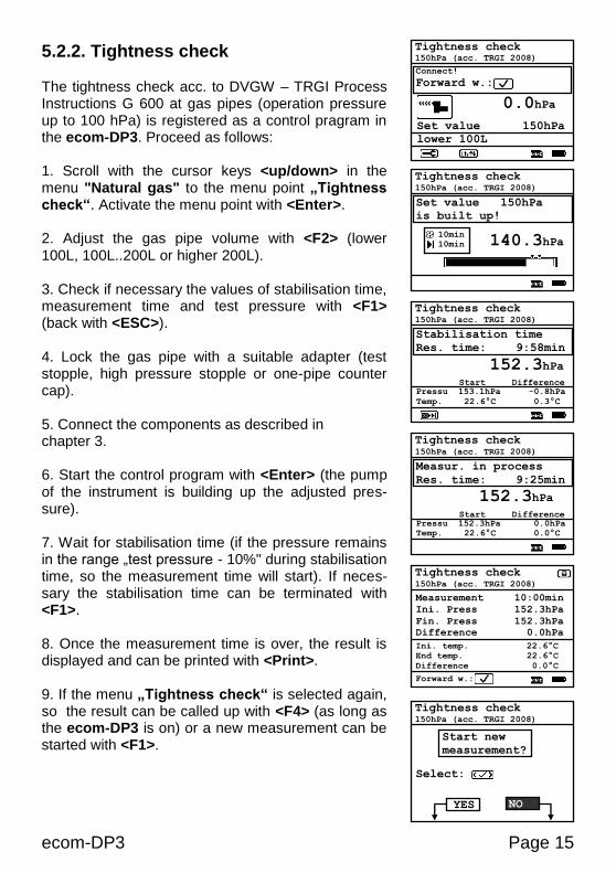
5.2.2. Tightness check The tightness check acc. to DVGW – TRGI Process Instructions G 600 at gas pipes (operation pressure up to 100 hPa) is registered as a control pragram in the ecom-DP3. Proceed as follows: 1. Scroll with the cursor keys <up/down> in the menu "Natural gas" to the menu point „Tightness check“. Activate the menu point with <Enter>. 2. Adjust the gas pipe volume with <F2> (lower 100L, 100L..200L or higher 200L). 3. Check if necessary the values of stabilisation time, measurement time and test pressure with <F1> (back with <ESC>). 4. Lock the gas pipe with a suitable adapter (test stopple, high pressure stopple or one-pipe counter cap). 5. Connect the components as described in chapter 3. 6. Start the control program with <Enter> (the pump of the instrument is building up the adjusted pres-sure). 7. Wait for stabilisation time (if the pressure remains in the range „test pressure - 10%" during stabilisation time, so the measurement time will start). If neces-sary the stabilisation time can be terminated with <F1>. 8. Once the measurement time is over, the result is displayed and can be printed with <Print>. 9. If the menu „Tightness check“ is selected again, so the result can be called up with <F4> (as long as the ecom-DP3 is on) or a new measurement can be started with <F1>.
Tightness check 150hPa (acc. TRGI 2008)
Stabilisation time
Res. time: 9:58min
Pressu 153.1hPa -0.8hPa
Temp. 22.6°C 0.3°C
Start Difference
152.3hPa
Tightness check 150hPa (acc. TRGI 2008)
Measur. in process
Res. time: 9:25min
Pressu 152.3hPa 0.0hPa
Temp. 22.6°C 0.0°C
Start Difference
152.3hPa
Tightness check 150hPa (acc. TRGI 2008)
Set value 150hPa
is built up!
140.3hPa 10min
10min
Tightness check 150hPa (acc. TRGI 2008)
Measurement 10:00min
Ini. Press 152.3hPa
Fin. Press 152.3hPa
Difference 0.0hPa Ini. temp. 22.6°C
End temp. 22.6°C
Difference 0.0°C
Forward w.:
Tightness check 150hPa (acc. TRGI 2008)
Start new
measurement?
Select:
YES NO
Tightness check 150hPa (acc. TRGI 2008)
Connect!
Forward w.:
Set value 150hPa
lower 100L
0.0hPa
Page 16 ecom-DP3
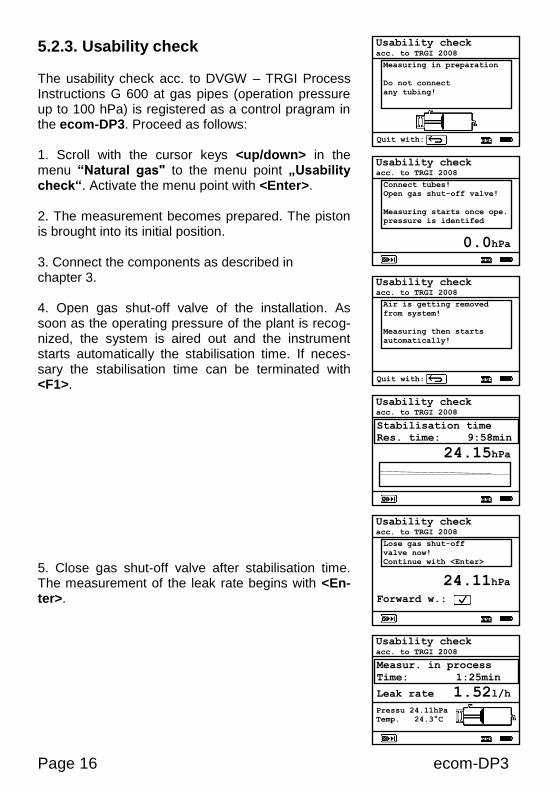
5.2.3. Usability check The usability check acc. to DVGW – TRGI Process Instructions G 600 at gas pipes (operation pressure up to 100 hPa) is registered as a control pragram in the ecom-DP3. Proceed as follows: 1. Scroll with the cursor keys <up/down> in the menu “Natural gas" to the menu point „Usability check“. Activate the menu point with <Enter>. 2. The measurement becomes prepared. The piston is brought into its initial position. 3. Connect the components as described in chapter 3. 4. Open gas shut-off valve of the installation. As soon as the operating pressure of the plant is recog-nized, the system is aired out and the instrument starts automatically the stabilisation time. If neces-sary the stabilisation time can be terminated with <F1>. 5. Close gas shut-off valve after stabilisation time. The measurement of the leak rate begins with <En-ter>.
Usability check acc. to TRGI 2008
Connect tubes!
Open gas shut-off valve!
Measuring starts once ope.
pressure is identifed
0.0hPa
Usability check acc. to TRGI 2008
Stabilisation time
Res. time: 9:58min
24.15hPa
Usability check acc. to TRGI 2008
Measur. in process
Time: 1:25min
Leak rate 1.52l/h Pressu 24.11hPa
Temp. 24.3°C
Forward w.:
Usability check acc. to TRGI 2008
Lose gas shut-off
valve now!
Continue with <Enter>
24.11hPa
Usability check acc. to TRGI 2008
Air is getting removed
from system!
Measuring then starts
automatically!
Quit with:
Usability check acc. to TRGI 2008
Measuring in preparation
Do not connect
any tubing!
Quit with:
ecom-DP3 Page 17
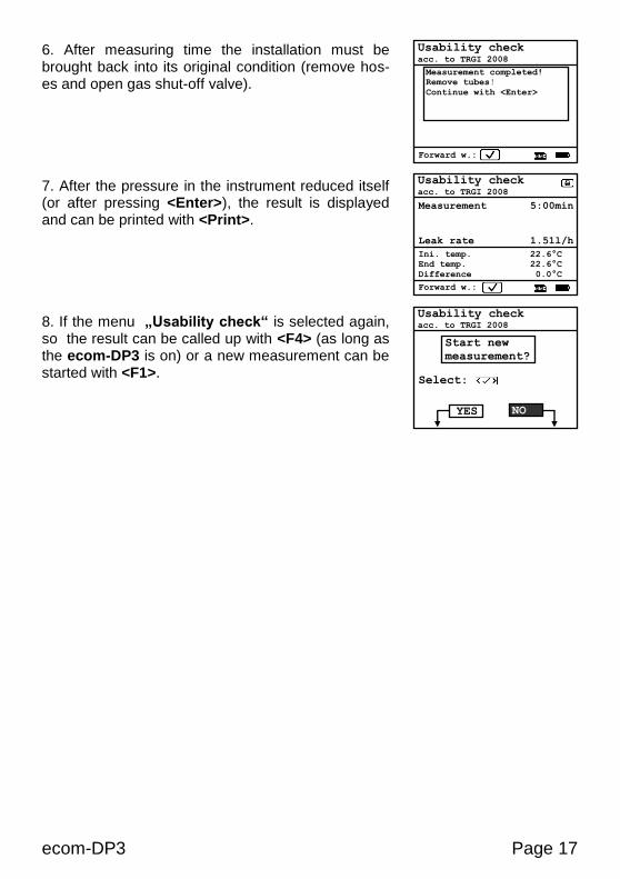
6. After measuring time the installation must be brought back into its original condition (remove hos-es and open gas shut-off valve). 7. After the pressure in the instrument reduced itself (or after pressing <Enter>), the result is displayed and can be printed with <Print>. 8. If the menu „Usability check“ is selected again, so the result can be called up with <F4> (as long as the ecom-DP3 is on) or a new measurement can be started with <F1>.
Usability check acc. to TRGI 2008
Measurement 5:00min
Leak rate 1.51l/h Ini. temp. 22.6°C
End temp. 22.6°C
Difference 0.0°C
Forward w.:
Usability check acc. to TRGI 2008
Start new
measurement?
Select:
YES NO
Usability check acc. to TRGI 2008
Measurement completed!
Remove tubes!
Continue with <Enter>
Forward w.:
Page 18 ecom-DP3
5.3. Liquid gas
5.3.1. Tightness check
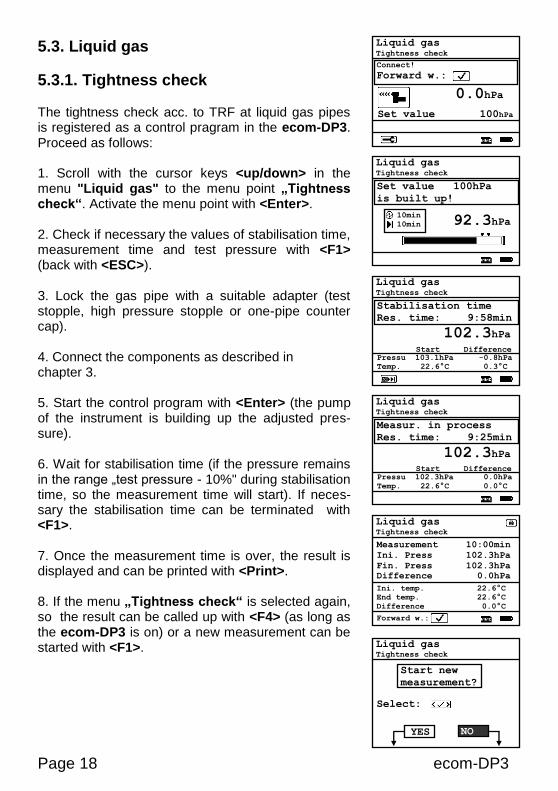
The tightness check acc. to TRF at liquid gas pipes is registered as a control pragram in the ecom-DP3. Proceed as follows: 1. Scroll with the cursor keys <up/down> in the menu "Liquid gas" to the menu point „Tightness check“. Activate the menu point with <Enter>. 2. Check if necessary the values of stabilisation time, measurement time and test pressure with <F1> (back with <ESC>). 3. Lock the gas pipe with a suitable adapter (test stopple, high pressure stopple or one-pipe counter cap). 4. Connect the components as described in chapter 3. 5. Start the control program with <Enter> (the pump of the instrument is building up the adjusted pres-sure). 6. Wait for stabilisation time (if the pressure remains in the range „test pressure - 10%" during stabilisation time, so the measurement time will start). If neces-sary the stabilisation time can be terminated with <F1>. 7. Once the measurement time is over, the result is displayed and can be printed with <Print>. 8. If the menu „Tightness check“ is selected again, so the result can be called up with <F4> (as long as the ecom-DP3 is on) or a new measurement can be started with <F1>.
Liquid gas Tightness check
Connect!
Forward w.:
Set value 100hPa
0.0hPa
Liquid gas Tightness check
Stabilisation time
Res. time: 9:58min
Pressu 103.1hPa -0.8hPa
Temp. 22.6°C 0.3°C
Start Difference
102.3hPa
Liquid gas Tightness check
Measur. in process
Res. time: 9:25min
Pressu 102.3hPa 0.0hPa
Temp. 22.6°C 0.0°C
Start Difference
102.3hPa
Liquid gas Tightness check
Set value 100hPa
is built up!
92.3hPa 10min
10min
Liquid gas Tightness check
Measurement 10:00min
Ini. Press 102.3hPa
Fin. Press 102.3hPa
Difference 0.0hPa Ini. temp. 22.6°C
End temp. 22.6°C
Difference 0.0°C Forward w.:
Liquid gas Tightness check
Start new
measurement?
Select:
YES
NO
ecom-DP3 Page 19
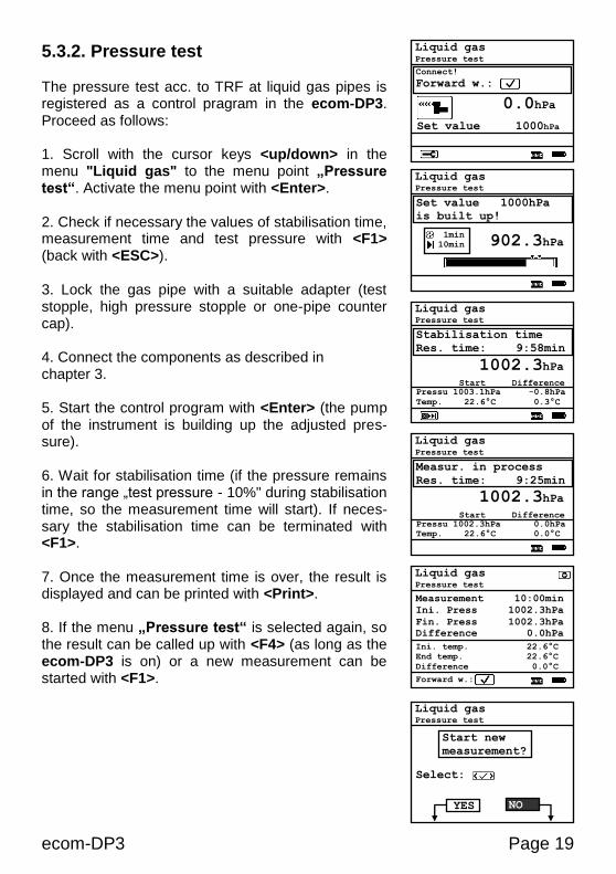
5.3.2. Pressure test The pressure test acc. to TRF at liquid gas pipes is registered as a control pragram in the ecom-DP3. Proceed as follows: 1. Scroll with the cursor keys <up/down> in the menu "Liquid gas" to the menu point „Pressure test“. Activate the menu point with <Enter>. 2. Check if necessary the values of stabilisation time, measurement time and test pressure with <F1> (back with <ESC>). 3. Lock the gas pipe with a suitable adapter (test stopple, high pressure stopple or one-pipe counter cap). 4. Connect the components as described in chapter 3. 5. Start the control program with <Enter> (the pump of the instrument is building up the adjusted pres-sure). 6. Wait for stabilisation time (if the pressure remains in the range „test pressure - 10%" during stabilisation time, so the measurement time will start). If neces-sary the stabilisation time can be terminated with <F1>. 7. Once the measurement time is over, the result is displayed and can be printed with <Print>. 8. If the menu „Pressure test“ is selected again, so the result can be called up with <F4> (as long as the ecom-DP3 is on) or a new measurement can be started with <F1>.
Liquid gas Pressure test
Stabilisation time
Res. time: 9:58min
Pressu 1003.1hPa -0.8hPa
Temp. 22.6°C 0.3°C
Start Difference
1002.3hPa
Liquid gas Pressure test
Measur. in process
Res. time: 9:25min
Pressu 1002.3hPa 0.0hPa
Temp. 22.6°C 0.0°C
Start Difference
1002.3hPa
Liquid gas Pressure test
Set value 1000hPa
is built up!
902.3hPa 1min
10min
Liquid gas Pressure test
Measurement 10:00min
Ini. Press 1002.3hPa
Fin. Press 1002.3hPa
Difference 0.0hPa Ini. temp. 22.6°C
End temp. 22.6°C
Difference 0.0°C
Forward w.:
Liquid gas Pressure test
Start new
measurement?
Select:
YES NO
Liquid gas Pressure test
Connect!
Forward w.:
Set value 1000hPa
0.0hPa
Page 20 ecom-DP3
5.3.3. Pressure test 0 – 40 bar
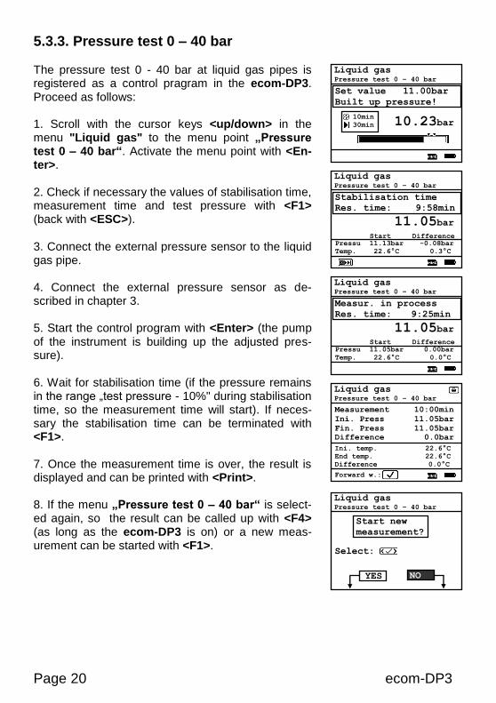
The pressure test 0 - 40 bar at liquid gas pipes is registered as a control pragram in the ecom-DP3. Proceed as follows: 1. Scroll with the cursor keys <up/down> in the menu "Liquid gas" to the menu point „Pressure test 0 – 40 bar“. Activate the menu point with <En-ter>. 2. Check if necessary the values of stabilisation time, measurement time and test pressure with <F1> (back with <ESC>). 3. Connect the external pressure sensor to the liquid gas pipe. 4. Connect the external pressure sensor as de-scribed in chapter 3. 5. Start the control program with <Enter> (the pump of the instrument is building up the adjusted pres-sure). 6. Wait for stabilisation time (if the pressure remains in the range „test pressure - 10%" during stabilisation time, so the measurement time will start). If neces-sary the stabilisation time can be terminated with <F1>. 7. Once the measurement time is over, the result is displayed and can be printed with <Print>. 8. If the menu „Pressure test 0 – 40 bar“ is select-ed again, so the result can be called up with <F4> (as long as the ecom-DP3 is on) or a new meas-urement can be started with <F1>.
Liquid gas Pressure test 0 – 40 bar
Stabilisation time
Res. time: 9:58min
Pressu 11.13bar -0.08bar
Temp. 22.6°C 0.3°C
Start Difference
11.05bar
Liquid gas Pressure test 0 – 40 bar
Measur. in process
Res. time: 9:25min
Pressu 11.05bar 0.00bar
Temp. 22.6°C 0.0°C
Start Difference
11.05bar
Liquid gas Pressure test 0 – 40 bar
Set value 11.00bar
Built up pressure!
10.23bar 10min
30min
Liquid gas Pressure test 0 – 40 bar
Measurement 10:00min
Ini. Press 11.05bar
Fin. Press 11.05bar
Difference 0.0bar Ini. temp. 22.6°C
End temp. 22.6°C
Difference 0.0°C
Forward w.:
Liquid gas Pressure test 0 – 40 bar
Start new
measurement?
Select:
YES NO

ecom-DP3 Page 21
5.4. Drinking water (option) 5.4.1. Drinking water plant (wet) 5.4.1.1. Function test The function test acc. to DIN EN 806-4 at drinking water pipes is registered as a control pragram in the ecom-DP3. Proceed as follows: 1. Scroll with the cursor keys <up/down> in the menu "Drinking water / Drinking water plant wet" to the menu point „Function test wet“. Activate the menu point with <Enter>. 2. Check if necessary the values of stabilisation time, measurement time and test pressure with <F1> (back with <ESC>). 3. Connect the external pressure sensor to the drinking water pipe. 4. Connect the external pressure sensor as de-scribed in chapter 3. 5. Start the control program with <Enter> and and built up the adjusted pressure. 6. Wait for stabilisation time (if the pressure remains in the range „test pressure +/- 10%" during stabilisa-tion time, so the measurement time will start). If nec-essary the stabilisation time can be terminated with <F1>. 7. Once the measurement time is over, the result is displayed and can be printed with <Print>. 8. If the menu „Function test wet“ is selected again, so the result can be called up with <F4> (as long as the ecom-DP3 is on) or a new measurement can be started with <F1>.
Drinking water plant Funkcion test wet
Stabilisation time
Res. time: 29:58min
Pressu 6.13bar -0.08bar
Temp. 22.6°C 0.3°C
Start Difference
6.05bar
Drinking water plant Funkcion test wet
Measur. in process
Res. time: 14:25min
Pressu 6.05bar 0.00bar
Temp. 22.6°C 0.0°C
Start Difference
6.05bar
Drinking water plant Funkcion test wet
Set value 6.00bar
Built up pressure!
5.23bar 30min
15min
Drinking water plant Funkcion test wet
Measurement 15:00min
Ini. Press 6.05bar
Fin. Press 6.05bar
Difference 0.0bar Ini. temp. 22.6°C
End temp. 22.6°C
Difference 0.0°C
Forward w.:
Drinking water plant Funkcion test wet
Start new
measurement?
Select:
YES NO
Page 22 ecom-DP3
5.4.1.2. Pressure test
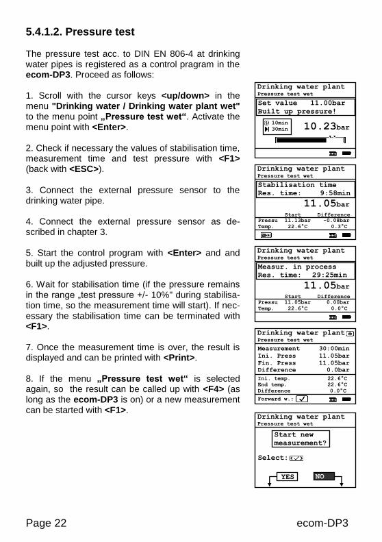
The pressure test acc. to DIN EN 806-4 at drinking water pipes is registered as a control pragram in the ecom-DP3. Proceed as follows: 1. Scroll with the cursor keys <up/down> in the menu "Drinking water / Drinking water plant wet" to the menu point „Pressure test wet“. Activate the menu point with <Enter>. 2. Check if necessary the values of stabilisation time, measurement time and test pressure with <F1> (back with <ESC>). 3. Connect the external pressure sensor to the drinking water pipe. 4. Connect the external pressure sensor as de-scribed in chapter 3. 5. Start the control program with <Enter> and and built up the adjusted pressure. 6. Wait for stabilisation time (if the pressure remains in the range „test pressure +/- 10%" during stabilisa-tion time, so the measurement time will start). If nec-essary the stabilisation time can be terminated with <F1>. 7. Once the measurement time is over, the result is displayed and can be printed with <Print>. 8. If the menu „Pressure test wet“ is selected again, so the result can be called up with <F4> (as long as the ecom-DP3 is on) or a new measurement can be started with <F1>.
Drinking water plant Pressure test wet
Stabilisation time
Res. time: 9:58min
Pressu 11.13bar -0.08bar
Temp. 22.6°C 0.3°C
Start Difference
11.05bar
Drinking water plant Pressure test wet
Measur. in process
Res. time: 29:25min
Pressu 11.05bar 0.00bar
Temp. 22.6°C 0.0°C
Start Difference
11.05bar
Drinking water plant Pressure test wet
Set value 11.00bar
Built up pressure!
10.23bar 10min
30min
Drinking water plant Pressure test wet
Measurement 30:00min
Ini. Press 11.05bar
Fin. Press 11.05bar
Difference 0.0bar Ini. temp. 22.6°C
End temp. 22.6°C
Difference 0.0°C
Forward w.:
Drinking water plant Pressure test wet
Start new
measurement?
Select:
YES NO

ecom-DP3 Page 23
5.4.1.3. Extended test The extebded test acc. to DIN EN 806-4 at drinking water pipes is registered as a control pragram in the ecom-DP3. Proceed as follows: 1. Scroll with the cursor keys <up/down> in the menu "Drinking water / Drinking water plant wet" to the menu point „Extended test wet“. Activate the menu point with <Enter>. 2. Check if necessary the values of stabilisation time, measurement time and test pressure with <F1> (back with <ESC>). 3. Connect the external pressure sensor to the drinking water pipe. 4. Connect the external pressure sensor as de-scribed in chapter 3. 5. Start the control program with <Enter> and built up the adjusted pressure. 6. Wait for stabilisation time (if the pressure remains in the range „test pressure +/- 10%" during stabilisa-tion time, so the measurement time will start). If nec-essary the stabilisation time can be terminated with <F1>. 7. Once the measurement time is over, the result is displayed and can be printed with <Print>. 8. If the menu „Extended test wet“ is selected again, so the result can be called up with <F4> (as long as the ecom-DP3 is on) or a new measurement can be started with <F1>.
Drinking water plant Extended test wet
Stabilisation time
Res. time: 9:58min
Pressu 5.63bar -0.08bar
Temp. 22.6°C 0.3°C
Start Difference
5.55bar
Drinking water plant Extended test wet
Measur. in process
Res. time: 1:59std
Pressu 5.55bar 0.00bar
Temp. 22.6°C 0.0°C
Start Difference
5.55bar
Drinking water plant Extended test wet
Set value 5.50bar
Built up pressure!
5.23bar 10min
120min
Drinking water plant Extended test wet
Measurement 2.00std
Ini. Press 5.55bar
Fin. Press 5.55bar
Difference 0.0bar Ini. temp. 22.6°C
End temp. 22.6°C
Difference 0.0°C
Forward w.:
Drinking water plant Extended test wet
Start new
measurement?
Select:
YES NO
Page 24 ecom-DP3
5.4.2. Drinking water plant (dry) 5.4.2.1. Tightness check
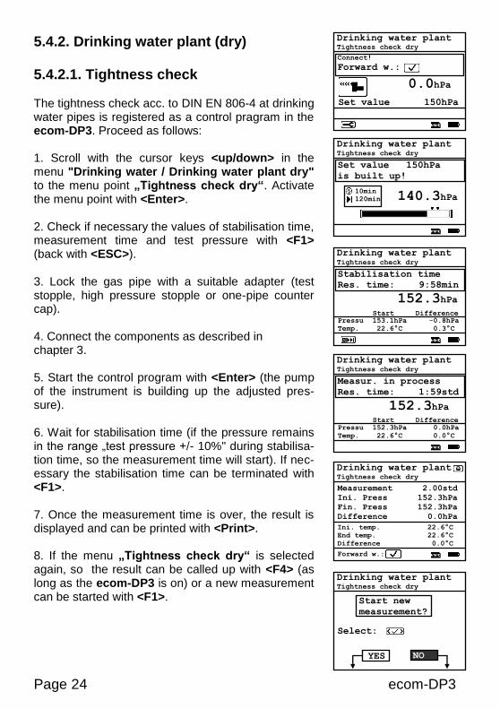
The tightness check acc. to DIN EN 806-4 at drinking water pipes is registered as a control pragram in the ecom-DP3. Proceed as follows: 1. Scroll with the cursor keys <up/down> in the menu "Drinking water / Drinking water plant dry" to the menu point „Tightness check dry“. Activate the menu point with <Enter>. 2. Check if necessary the values of stabilisation time, measurement time and test pressure with <F1> (back with <ESC>). 3. Lock the gas pipe with a suitable adapter (test stopple, high pressure stopple or one-pipe counter cap). 4. Connect the components as described in chapter 3. 5. Start the control program with <Enter> (the pump of the instrument is building up the adjusted pres-sure). 6. Wait for stabilisation time (if the pressure remains in the range „test pressure +/- 10%" during stabilisa-tion time, so the measurement time will start). If nec-essary the stabilisation time can be terminated with <F1>. 7. Once the measurement time is over, the result is displayed and can be printed with <Print>. 8. If the menu „Tightness check dry“ is selected again, so the result can be called up with <F4> (as long as the ecom-DP3 is on) or a new measurement can be started with <F1>.
Drinking water plant Tightness check dry
Stabilisation time
Res. time: 9:58min
Pressu 153.1hPa -0.8hPa
Temp. 22.6°C 0.3°C
Start Difference
152.3hPa
Drinking water plant Tightness check dry
Measur. in process
Res. time: 1:59std
Pressu 152.3hPa 0.0hPa
Temp. 22.6°C 0.0°C
Start Difference
152.3hPa
Drinking water plant Tightness check dry
Set value 150hPa
is built up!
140.3hPa 10min
120min
Drinking water plant Tightness check dry
Measurement 2.00std
Ini. Press 152.3hPa
Fin. Press 152.3hPa
Difference 0.0hPa
Ini. temp. 22.6°C End temp. 22.6°C
Difference 0.0°C
Forward w.:
Drinking water plant Tightness check dry
Start new
measurement?
Select:
YES
NO
Drinking water plant Tightness check dry
Connect!
Forward w.:
Set value 150hPa
0.0hPa
ecom-DP3 Page 25
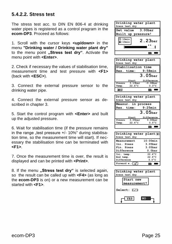
5.4.2.2. Stress test The stress test acc. to DIN EN 806-4 at drinking water pipes is registered as a control pragram in the ecom-DP3. Proceed as follows: 1. Scroll with the cursor keys <up/down> in the menu "Drinking water / Drinking water plant dry" to the menu point „Stress test dry“. Activate the menu point with <Enter>. 2. Check if necessary the values of stabilisation time, measurement time and test pressure with <F1> (back with <ESC>). 3. Connect the external pressure sensor to the drinking water pipe. 4. Connect the external pressure sensor as de-scribed in chapter 3. 5. Start the control program with <Enter> and built up the adjusted pressure. 6. Wait for stabilisation time (if the pressure remains in the range „test pressure +/- 10%" during stabilisa-tion time, so the measurement time will start). If nec-essary the stabilisation time can be terminated with <F1>. 7. Once the measurement time is over, the result is displayed and can be printed with <Print>. 8. If the menu „Stress test dry“ is selected again, so the result can be called up with <F4> (as long as the ecom-DP3 is on) or a new measurement can be started with <F1>.
Drinking water plant Sress test dry
Stabilisation time
Res. time: 9:58min
Pressu 3.13bar -0.08bar
Temp. 22.6°C 0.3°C
Start Difference
3.05bar
Drinking water plant Sress test dry
Measur. in process
Res. time: 9:25min
Pressu 3.05bar 0.00bar
Temp. 22.6°C 0.0°C
Start Difference
3.05bar
Drinking water plant Sress test dry
Set value 3.00bar
Built up pressure!
2.23bar 10min
10min
Drinking water plant Sress test dry
Measurement 10:00min
Ini. Press 3.05bar
Fin. Press 3.05bar
Difference 0.0bar
Ini. temp. 22.6°C
End temp. 22.6°C
Difference 0.0°C
Forward w.:
Drinking water plant Sress test dry
Start new
measurement?
Select:
YES NO
Page 26 ecom-DP3
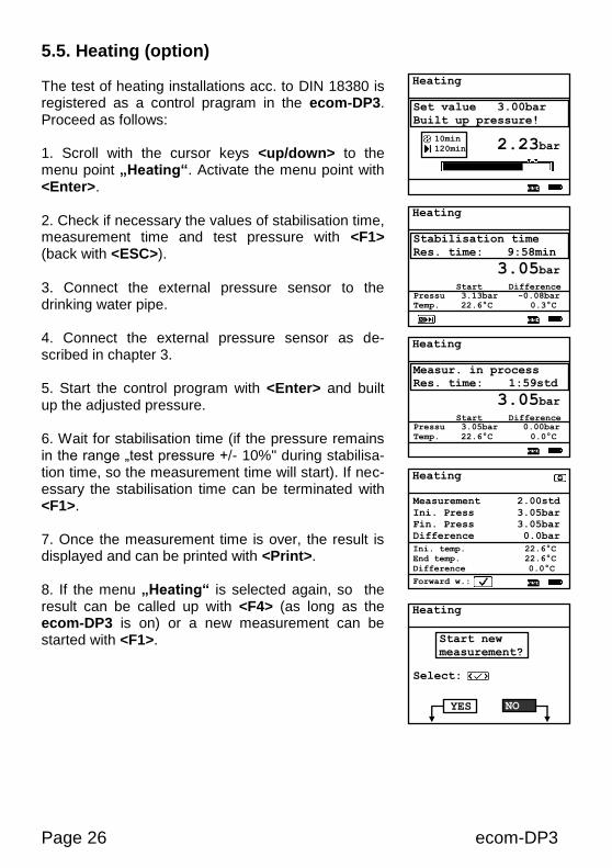
5.5. Heating (option) The test of heating installations acc. to DIN 18380 is registered as a control pragram in the ecom-DP3. Proceed as follows: 1. Scroll with the cursor keys <up/down> to the menu point „Heating“. Activate the menu point with <Enter>. 2. Check if necessary the values of stabilisation time, measurement time and test pressure with <F1> (back with <ESC>). 3. Connect the external pressure sensor to the drinking water pipe. 4. Connect the external pressure sensor as de-scribed in chapter 3. 5. Start the control program with <Enter> and built up the adjusted pressure. 6. Wait for stabilisation time (if the pressure remains in the range „test pressure +/- 10%" during stabilisa-tion time, so the measurement time will start). If nec-essary the stabilisation time can be terminated with <F1>. 7. Once the measurement time is over, the result is displayed and can be printed with <Print>. 8. If the menu „Heating“ is selected again, so the result can be called up with <F4> (as long as the ecom-DP3 is on) or a new measurement can be started with <F1>.
Heating
Stabilisation time
Res. time: 9:58min
Pressu 3.13bar -0.08bar
Temp. 22.6°C 0.3°C
Start Difference
3.05bar
Heating
Measur. in process
Res. time: 1:59std
Pressu 3.05bar 0.00bar
Temp. 22.6°C 0.0°C
Start Difference
3.05bar
Heating
Set value 3.00bar
Built up pressure!
2.23bar 10min
120min
Heating
Measurement 2.00std
Ini. Press 3.05bar
Fin. Press 3.05bar
Difference 0.0bar
Ini. temp. 22.6°C
End temp. 22.6°C
Difference 0.0°C
Forward w.:
Heating
Start new
measurement?
Select:
YES NO
ecom-DP3 Page 27
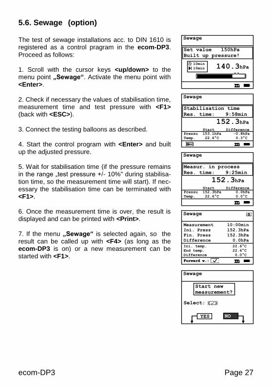
5.6. Sewage (option) The test of sewage installations acc. to DIN 1610 is registered as a control pragram in the ecom-DP3. Proceed as follows: 1. Scroll with the cursor keys <up/down> to the menu point „Sewage“. Activate the menu point with <Enter>. 2. Check if necessary the values of stabilisation time, measurement time and test pressure with <F1> (back with <ESC>). 3. Connect the testing balloons as described. 4. Start the control program with <Enter> and built up the adjusted pressure. 5. Wait for stabilisation time (if the pressure remains in the range „test pressure +/- 10%" during stabilisa-tion time, so the measurement time will start). If nec-essary the stabilisation time can be terminated with <F1>. 6. Once the measurement time is over, the result is displayed and can be printed with <Print>. 7. If the menu „Sewage“ is selected again, so the result can be called up with <F4> (as long as the ecom-DP3 is on) or a new measurement can be started with <F1>.
Sewage
Stabilisation time
Res. time: 9:58min
Pressu 153.1hPa -0.8hPa
Temp. 22.6°C 0.3°C
Start Difference
152.3hPa
Sewage
Measur. in process
Res. time: 9:25min
Pressu 152.3hPa 0.0hPa
Temp. 22.6°C 0.0°C
Start Difference
152.3hPa
Forward w.:
Sewage
Set value 150hPa
Built up pressure!
140.3hPa 10min
10min
Sewage
Measurement 10:00min
Ini. Press 152.3hPa
Fin. Press 152.3hPa
Difference 0.0hPa
Ini. temp. 22.6°C End temp. 22.6°C
Difference 0.0°C
Forward w.:
Sewage
Start new
measurement?
Select:
YES NO
Page 28 ecom-DP3
6. More measurements
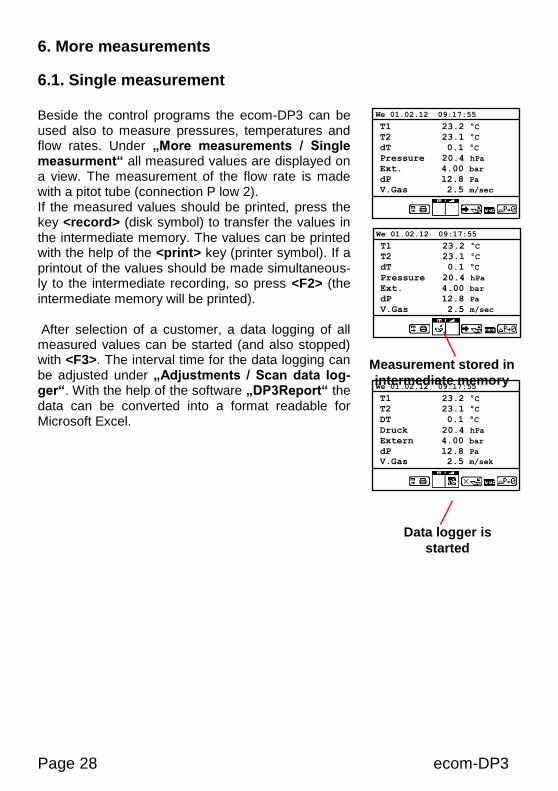
6.1. Single measurement Beside the control programs the ecom-DP3 can be used also to measure pressures, temperatures and flow rates. Under „More measurements / Single measurment“ all measured values are displayed on a view. The measurement of the flow rate is made with a pitot tube (connection P low 2). If the measured values should be printed, press the key <record> (disk symbol) to transfer the values in the intermediate memory. The values can be printed with the help of the <print> key (printer symbol). If a printout of the values should be made simultaneous-ly to the intermediate recording, so press <F2> (the intermediate memory will be printed). After selection of a customer, a data logging of all measured values can be started (and also stopped) with <F3>. The interval time for the data logging can be adjusted under „Adjustments / Scan data log-ger“. With the help of the software „DP3Report“ the data can be converted into a format readable for Microsoft Excel.
T1 23.2 °C
T2 23.1 °C
DT 0.1 °C
Druck 20.4 hPa
Extern 4.00 bar
dP 12.8 Pa
V.Gas 2.5 m/sek
We 01.02.12 09:17:55
T1 23.2 °C
T2 23.1 °C
dT 0.1 °C
Pressure 20.4 hPa
Ext. 4.00 bar
dP 12.8 Pa
V.Gas 2.5 m/sec
We 01.02.12 09:17:55
Measurement stored in
intermediate memory
Data logger is
started
T1 23.2 °C
T2 23.1 °C
dT 0.1 °C
Pressure 20.4 hPa
Ext. 4.00 bar
dP 12.8 Pa
V.Gas 2.5 m/sec
We 01.02.12 09:17:55
ecom-DP3 Page 29
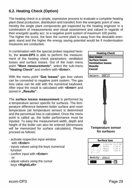
6.2. Heating Check (Option) The heating check is a simple, expressive process to evaluate a complete heating plant (heat production, distribution and transfer) from the energetic point of view. Hereby the single plant components get inspected by the heating engineer in a combination of measurements and visual assessment and valued in regards of their energetic quality acc. to a negative point system of maximum 100 points. The higher the score, the farer the current plant is away from the desirable ener-getic stand and the higher the energy saving potential would be if modernisation measures are conducted. In combination with the special probes required here-to, the ecom-DP3 is able to perform the measure-ment of the heating check parameters: ventilation losses and surface losses. Out of the main menu point "More measurements", select the sub-menu "Heating Check" and confirm with <Enter>. With the menu point “Gas losses” gas loss values can be converted to negative point system. The gas loss value can be edit with the numerical keyboard. After input the result is calculated with <Enter> and stored in „Results“.
The surface losses measurement is performed by a temperature sensor specific for surfaces. The tem-perature difference between boiler surface and room temperature (air temperature sensor) is determined and the percentual loss is calculated. Once the menu point is called up, the boiler performance must be inputed. To easy the measurement width, depth and height of the boiler can also be entered (dimensions will be memorized for surface calculation). Please proceed as follows: - activate respective input window with <Enter> - inputs values using the keys numerical function - confirm input with <Enter> or: - adjust values using the cursor keys <Right/Left>
Gas losses Surface losses Ventilation losses Results Cancel
Heating Check
Select:
Temperature sensor
for surfaces
P.Boiler 24.5 kW
Width 1.20 m
Depth 1.20 m
Hight 1.20 m
Modify:
Surface loss
Start Start
Page 30 ecom-DP3
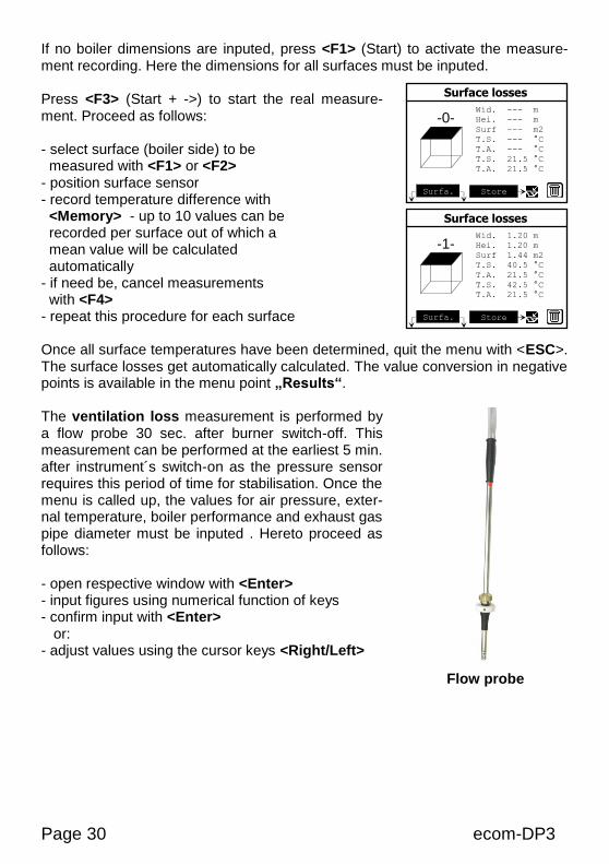
If no boiler dimensions are inputed, press <F1> (Start) to activate the measure-ment recording. Here the dimensions for all surfaces must be inputed. Press <F3> (Start + ->) to start the real measure-ment. Proceed as follows: - select surface (boiler side) to be measured with <F1> or <F2> - position surface sensor - record temperature difference with <Memory> - up to 10 values can be recorded per surface out of which a mean value will be calculated automatically - if need be, cancel measurements with <F4> - repeat this procedure for each surface Once all surface temperatures have been determined, quit the menu with <ESC>. The surface losses get automatically calculated. The value conversion in negative points is available in the menu point „Results“. The ventilation loss measurement is performed by a flow probe 30 sec. after burner switch-off. This measurement can be performed at the earliest 5 min. after instrument´s switch-on as the pressure sensor requires this period of time for stabilisation. Once the menu is called up, the values for air pressure, exter-nal temperature, boiler performance and exhaust gas pipe diameter must be inputed . Hereto proceed as follows: - open respective window with <Enter> - input figures using numerical function of keys - confirm input with <Enter> or: - adjust values using the cursor keys <Right/Left>
Flow probe
Wid. --- m
Hei. --- m
Surf --- m2
T.S. --- °C
T.A. --- °C
T.S. 21.5 °C
T.A. 21.5 °C
Surface losses
Store
Surfa.
-0-
Wid. 1.20 m
Hei. 1.20 m
Surf 1.44 m2
T.S. 40.5 °C
T.A. 21.5 °C
T.S. 42.5 °C
T.A. 21.5 °C
Surface losses
Store
Surfa.
-1-
ecom-DP3 Page 31
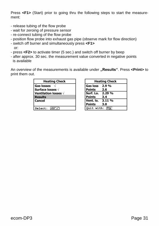
Press <F1> (Start) prior to going thru the following steps to start the measure-ment: - release tubing of the flow probe - wait for zeroing of pressure sensor - re-connect tubing of the flow probe - position flow probe into exhaust gas pipe (observe mark for flow direction) - switch off burner and simultaneously press <F1> or: - press <F2> to activate timer (5 sec.) and switch off burner by beep - after approx. 30 sec. the measurement value converted in negative points is available An overview of the measurements is available under „Results“. Press <Print> to print them out.
Gas loss 2.9 % Points 2.6 Surf. Lo. 2.29 % Points 3.4 Vent. lo. 3.11 % Points 3.0
Heating Check
Quit with:
Gas losses
Surface losses Ventilation losses
Results Cancel
Heating Check
Select:
Page 32 ecom-DP3
6.3. 4Pa measurement (option) The simultaneous operation of room-dependent firing place and air evacuation system can lead to dangerous low pressure conditions. With the ecom-DP3 it is possible to check the low pressure limit value of 4 Pa and to document in a dia-gramme the time course of the low pressure value. Once the menu point is called up, the measurement is to be performed as follows: - connect capillary hose for room where burner is installed to „-“ - connect capillary hose for reference place (staircase or outside air to „+“ - operate firing and evacuation systems with maximal performance - open window resp. connection door to burner room and check the correct evacuation of the exhaust gases - zero pressure sensor with <F4> - position capillary hose for reference location - start record pressure value course with <F1> (Start) (an acoustical signal is issued every 30 sec. which can be deactivated / re-activated by pressing <F2>) - record pressure by opened window resp. connection door - close window resp. connection door after approx. 30 sec. and check low pressure - after approx. 30 sec. open window resp. connection door and check zero point - close window resp. connection door after approx. 30 sec. and check low pressure - after approx. 30 sec. re-open window or connection door and check zero point - after approx. 30 sec. close window resp. connection door and check low pressure Once the measurement time is completed, the diagramme can be viewed on the display (use <F3> to emphasize illustration 1x, 2x, 4x, 8x times or A for automat-ic). Start a printout if needed with <Print>.

ecom-DP3 Page 33
6.4. Pressure check The pressure check (long term measurement up to 1500 hPa or 20 bar with external pressure sensor) is registered as a control pragram in the ecom-DP3. Proceed as follows: 1. Scroll with the cursor keys <up/down> in the menu "More measurements" to the menu point „Pressure check“. Activate the menu point with <Enter>. 2. Check if necessary the values of stabilisation time, measurement time and test pressure with <F1> (back with <ESC>). If the measurement time is set to 0, thecontrol program runs until it is interrupted. 3. Lock the gas pipe with a suitable adapter (test stopple, high pressure stopple or one-pipe counter cap) or connect the external pressure sensor. 4. Connect the components as described in chapter 3. 5. Start the control program with <Enter> and built up the adjusted pressure. 6. If the internal sensor (up to 1500 hPa) is used, the needed pressure can be built up with the internal pump (switch on and off with <F3>). 7. Wait for stabilisation time. If necessary the stabili-sation time can be terminated with <F1>. 8. Once the measurement time is over (or with <En-ter> if measurement time = 0), the result is displayed and can be printed with <Print>. 9. If the menu „Pressure check“ is selected again, so the result can be called up with <F4> (as long as the ecom-DP3 is on) or a new measurement can be started with <F1>.
Pressure check 1,5Bar/1500hPa long tes
Stabilisation time
Res. time: 58sek
Pressu 1003.1hPa -0.8hPa
Temp. 22.6°C 0.3°C
Start Difference
1002.3hPa
Pressure check 1,5Bar/1500hPa long tes
Measur. in process
Res. time: 9:25min
Pressu 1002.3hPa 0.0hPa
Temp. 22.6°C 0.0°C
Start Difference
1002.3hPa
Pressure check 1,5Bar/1500hPa long tes
Measurement 10:00min
Ini. Press 1002.3hPa
Fin. Press 1002.3hPa
Difference 0.0hPa
Ini. temp. 22.6°C End temp. 22.6°C
Difference 0.0°C
Forward w.:
Pressure check 1,5Bar/1500hPa long tes
Start new
measurement?
Select:
YES NO
Pressure check 1,5Bar/1500hPa long tes
Build up pressure
Forward w.:
0.0hPa
Page 34 ecom-DP3
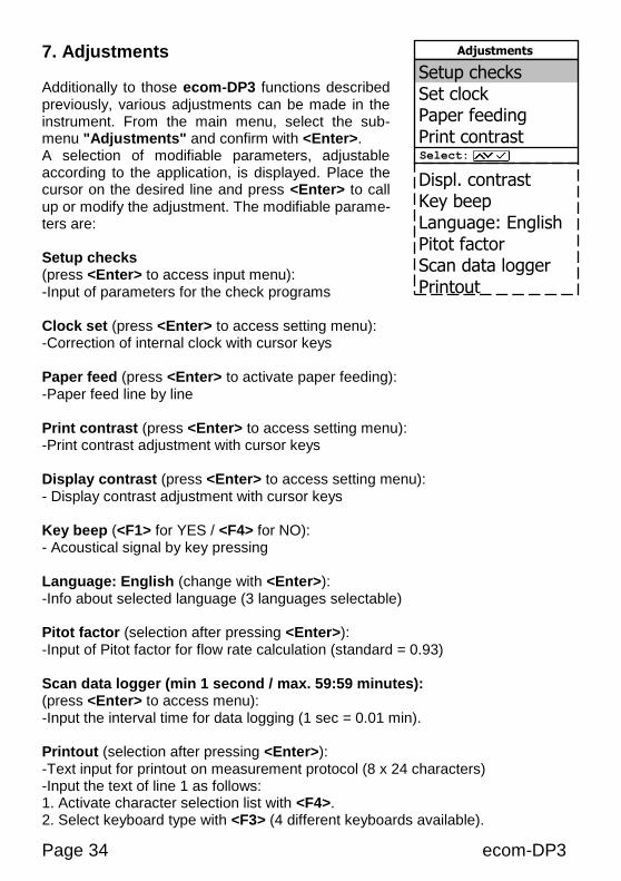
7. Adjustments
Additionally to those ecom-DP3 functions described previously, various adjustments can be made in the instrument. From the main menu, select the sub-menu "Adjustments" and confirm with <Enter>. A selection of modifiable parameters, adjustable according to the application, is displayed. Place the cursor on the desired line and press <Enter> to call up or modify the adjustment. The modifiable parame-ters are: Setup checks (press <Enter> to access input menu): -Input of parameters for the check programs Clock set (press <Enter> to access setting menu): -Correction of internal clock with cursor keys Paper feed (press <Enter> to activate paper feeding): -Paper feed line by line Print contrast (press <Enter> to access setting menu): -Print contrast adjustment with cursor keys Display contrast (press <Enter> to access setting menu): - Display contrast adjustment with cursor keys Key beep (<F1> for YES / <F4> for NO): - Acoustical signal by key pressing Language: English (change with <Enter>): -Info about selected language (3 languages selectable) Pitot factor (selection after pressing <Enter>): -Input of Pitot factor for flow rate calculation (standard = 0.93) Scan data logger (min 1 second / max. 59:59 minutes): (press <Enter> to access menu): -Input the interval time for data logging (1 sec = 0.01 min). Printout (selection after pressing <Enter>): -Text input for printout on measurement protocol (8 x 24 characters) -Input the text of line 1 as follows: 1. Activate character selection list with <F4>. 2. Select keyboard type with <F3> (4 different keyboards available).
Setup checks Set clock Paper feeding Print contrast Displ. contrast Key beep Language: English Pitot factor Scan data logger Printout
Select:
Adjustments
ecom-DP3 Page 35
3. Use the cursor keys to select the desired character (selected character is outlined by black background). 4. Confirm selection while pressing <Enter>. 5. Repeat procedure until desired text is complete. 6. Once input for line 1 is completed, deactivate the characters selection mode with <F4> and move to the second line with the cursor key <Down>. 7. Once all lines have been processed as desired, exit the menu with <ESC>.
Page 36 ecom-DP3
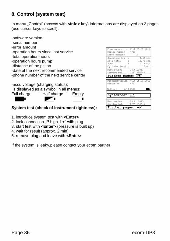
8. Control (system test) In menu „Control“ (access with <Info> key) informations are displayed on 2 pages (use cursor keys to scroll): -software version -serial number -error amount -operation hours since last service -total operation hours -operation hours pump -distance of the piston -date of the next recommended service -phone number of the next service center -accu voltage (charging status); is displayed as a symbol in all menus: Full charge Half charge Empty System test (check of instrument tightness): 1. introduce system test with <Enter> 2. lock connection „P high 1 +“ with plug 3. start test with <Enter> (pressure is built up) 4. wait for result (approx. 2 min) 5. remove plug and leave with <Enter> If the system is leaky,please contact your ecom partner.
Program version: V1.0 25.01.2012
Serial number : 4711
Error counter : 12
Further pages:
Operation hrs : 8.45 std
At a total : 18.75 std
Pump : 0.17 std
Cylinder (way) : 13 m
Next sevice : 25.01.2013
Service tel. : 02371/945-5
Programmversion: V1.0 25.01.2012
Geräte Nr. : 4711
Battery 6.73 Volt
Further pages:
Next sevice : 25.01.2013
Service tel. : 02371/945-5
Systemtest:
ecom-DP3 Page 37
9. Technical Data ecom-DP3 Power supply: -battery: Lithium-Ions 6 V 4,6 Ah -charger 230 V / 50 Hz~ Indication: -grafic display; backlit -resolution 240 x 160 Punkte -window approx. 79 x 53 mm Pressure range: -0 - 1500 hPa -0 - 20 bar (option / external sensor) -0 - 10 hPa (option / Pa sensor) Resolution: -0,1 hPa -0,01 bar (option / external sensor) -0,1 Pa (option / Pa sensor) Leak rate: -0 - 8 l/h Resolution: -0,1 l/h Temperature: -2 x 0 -100 °C (option / external temperature sensor) Resolution: -0,1 °C (option / external temperature sensor) Dimensions (LxWxH): -approx. 380 x 430 x 170 mm Weight: -complete with accessories approx. 9 kg Ambient temperature: -0 to 50 °C
Page 38 ecom-DP3
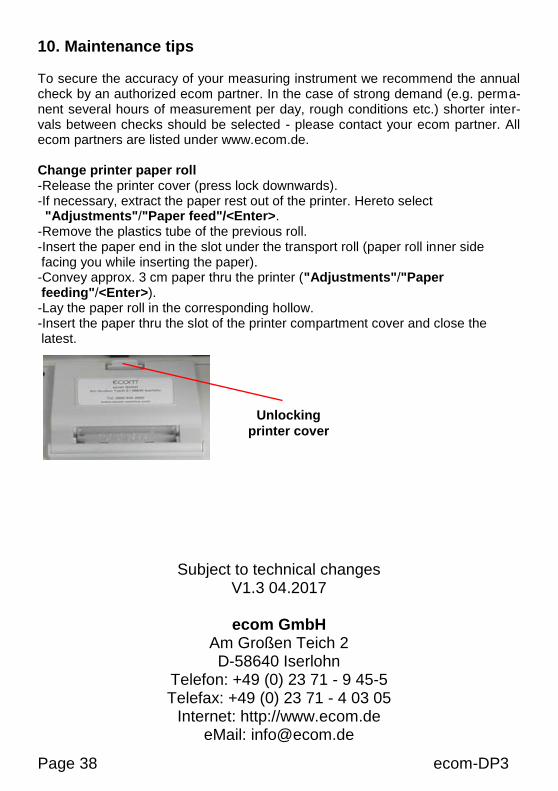
10. Maintenance tips To secure the accuracy of your measuring instrument we recommend the annual check by an authorized ecom partner. In the case of strong demand (e.g. perma-nent several hours of measurement per day, rough conditions etc.) shorter inter-vals between checks should be selected - please contact your ecom partner. All ecom partners are listed under www.ecom.de. Change printer paper roll -Release the printer cover (press lock downwards). -If necessary, extract the paper rest out of the printer. Hereto select "Adjustments"/"Paper feed"/<Enter>. -Remove the plastics tube of the previous roll. -Insert the paper end in the slot under the transport roll (paper roll inner side facing you while inserting the paper). -Convey approx. 3 cm paper thru the printer ("Adjustments"/"Paper feeding"/<Enter>). -Lay the paper roll in the corresponding hollow. -Insert the paper thru the slot of the printer compartment cover and close the latest.
Subject to technical changes V1.3 04.2017
ecom GmbH
Am Großen Teich 2 D-58640 Iserlohn
Telefon: +49 (0) 23 71 - 9 45-5 Telefax: +49 (0) 23 71 - 4 03 05
Internet: http://www.ecom.de eMail: [email protected]
Unlocking
printer cover