Embed Size (px)
Citation preview

QUALITY ASSURANCE PROJECT PLAN
A. PROJECT MANAGEMENT
A1. TITLE AND APPROVAL SHEET
TITLE: Analysis of Environmental Hazards Related to Hydraulic Fracturing EPA Interagency Agreement No. DW-89-92378101-0 LBNL Interagency Agreement No. WF009863
REVISION NUMBER: 1
DATE: July 22, 2013
CONTRACT SUPPORT: Lawrence Berkeley National Laboratory
_____________/s/__________________ July 15, 2013______ George J. Moridis, Principal Investigator Date
EPA APPROVALS:
_____________/s/__________________ ___July 15, 2013____ Stephen Kraemer, EPA Technical Research Date Lead for Scenario Evaluation & Modeling
_____________/s/__________________ ___July 22, 2013____ John M. Johnston, Chief, ERD Regulatory Date Support Branch
______________/s/_________________ ____July 18, 2013___ James Kitchens, ERD QA Manager Date
Disclaimer EPA does not consider this internal planning document an official Agency dissemination of information under the Agency's Information Quality Guidelines, because it is not being used to formulate or support a regulation or guidance; or to represent a final Agency decision or position. This planning document describes the overall quality assurance approach that will be used during the research study. Mention of trade names or commercial products in this planning document does not constitute endorsement or recommendation for use.
The EPA Quality System and the HF Research Study EPA requires that all data collected for the characterization of environmental processes and conditions are of the appropriate type and quality for their intended use. This is accomplished through an Agency-wide quality system for environmental data. Components of the EPA quality system can be found at http://www.epa.gov/quality/. EPA policy is based on the national consensus standard ANSI/ASQ E4-2004 Quality Systems for Environmental Data and Technology Programs: Requirements with Guidance for Use. This standard recommends a tiered approach that includes the development and use of Quality Management Plans (QMPs). The organizational units in EPA that generate and/or use environmental data are required to have Agency-approved QMPs. Programmatic QMPs are also written when program managers and their QA staff decide a program is of sufficient complexity to benefit from a QMP, as was done for the study of the potential impacts of hydraulic fracturing (HF) on drinking water resources. The HF QMP describes the program’s organizational structure, defines and assigns quality assurance (QA) and quality control (QC) responsibilities, and describes the processes and procedures used to plan, implement and assess the effectiveness of the quality system. The HF QMP is then supported by project-specific QA project plans (QAPPs). The QAPPs provide the technical details and associated QA/QC procedures for the research projects that address questions posed by EPA about the HF water cycle and as described in the Plan to Study the Potential Impacts of Hydraulic Fracturing on Drinking Water Resources (EPA/600/R11/122/November 2011/www.epa.gov/hydraulic fracturing). The results of the research projects will provide the foundation for EPA’s 2014 study report.
This QAPP provides information concerning the Well Injection Stage of the HF water cycle as found in Figure 1 of the HF QMP and as described in the HF Study Plan. Appendix A of the HF QMP includes the links between the HF Study Plan questions and those QAPPs available at the time the HF QMP was published.
Section A Revision No. 1
Date: July 22, 2013 Page 3 of 41
A2. TABLE OF CONTENTS A. PROJECT MANAGEMENT ....................................... i
A1. TITLE AND APPROVAL SHEET ................................... i A2. TABLE OF CONTENTS.......................................... 3
A3. DISTRIBUTION LIST ........................................... 4
A4. PROJECT / TASK ORGANIZATION ................................ 5
A5. PROBLEM DEFINITION / BACKGROUND ............................ 6
A6. PROJECT/TASK DESCRIPTION AND SCHEDULE ..................... 15
A7. QUALITY OBJECTIVES AND CRITERIA FOR MODEL INPUTS/OUTPUTS ... 22
A8. SPECIAL TRAINING REQUIREMENTS/CERTIFICATION ................ 26
A9. DOCUMENTS AND RECORDS ................................... 26
B. MEASUREMENT AND DATA ACQUISITION ......................... 29
B1. SAMPLING PROCESS DESIGN ................................... 29
B2. SAMPLING METHODS ......................................... 29
B3. SAMPLE HANDLING AND CUSTODY .............................. 29
B4. ANALYTICAL METHODS ...................................... 29
B5. QUALITY CONTROL .......................................... 29
B6. INSTRUMENT/EQUIPMENT TESTING, INSPECTION, AND MAINTENANCE .. 29
B7. INSTRUMENT/EQUIPMENT CALIBRATION ......................... 29
B8. INSPECTION/ACCEPTANCE OF SUPPLIES AND CONSUMABLES ......... 29
B9. NON-DIRECT MEASUREMENTS (DATA ACQUISITION REQUIREMENTS) ... 29
B10. DATA MANAGEMENT AND HARDWARE/SOFTWARE CONFIGURATION .. 29
C. ASSESSMENT AND OVERSIGHT .................................... 30
C1. ASSESSMENTS AND RESPONSE ACTIONS ........................ 30
C2. REPORTS TO MANAGEMENT .................................. 30
D. DATA VALIDATION AND USABILITY ............................. 31
REFERENCES .................................................... 32
Section A Revision No. 1
Date: July 22, 2013 Page 4 of 41
FIGURES
Note: Figures are not to scale. Representation as a scenario does not necessarily imply physical or geologic likelihood.
Figure 1. HF hypothetical failure scenario A ………………………………………………. 8
Figure 2. HF hypothetical failure scenario B ………………………………………………. 9
Figure 3. HF hypothetical failure scenario C ………………………………………………. 10
Figure 4. HF hypothetical failure scenario D ………………………………………………. 11
Figure 5. HF hypothetical failure scenario E ………………………………………………. 12
A3. DISTRIBUTION LIST
The following individuals will be provided electronic copies of the approved QA Project Plan. Their responsibilities are described in section A4.
Dr. George Moridis – LBNL, Berkeley, CA Dr. Matthew Reagan – LBNL, Berkeley, CA Dr. Jonny Rutqvist – LBNL, Berkeley, CA Dr. Jihoon Kim – LBNL, Berkeley, CA Dr. Peter Persoff – LBNL, Berkeley, CA Dr. James W. Weaver – EPA GWERD, Ada, OK Mr. James Kitchens – EPA ERD, Athens, GA Dr. Stephen Kraemer – EPA ERD, Athens, GA Dr. John M. Johnston – EPA ERD, Athens, GA Ms. Jeanne Briskin – EPA OSP, Washington, DC Dr. Jennifer Orme-Zavaleta – EPA NERL, RTP, NC Dr. Andrew Gillespie – EPA NERL, RTP, NC Ms. Michelle Henderson – EPA NERL, Cincinnati, OH Mr. Nathan Wiser – EPA R8, Denver, CO Dr. Charles Hillenbrand – EPA R2, New York, NY Dr. Junqi Huang – EPA GWERD, Ada, OK
Section A Revision No. 1
Date: July 22, 2013 Page 5 of 41
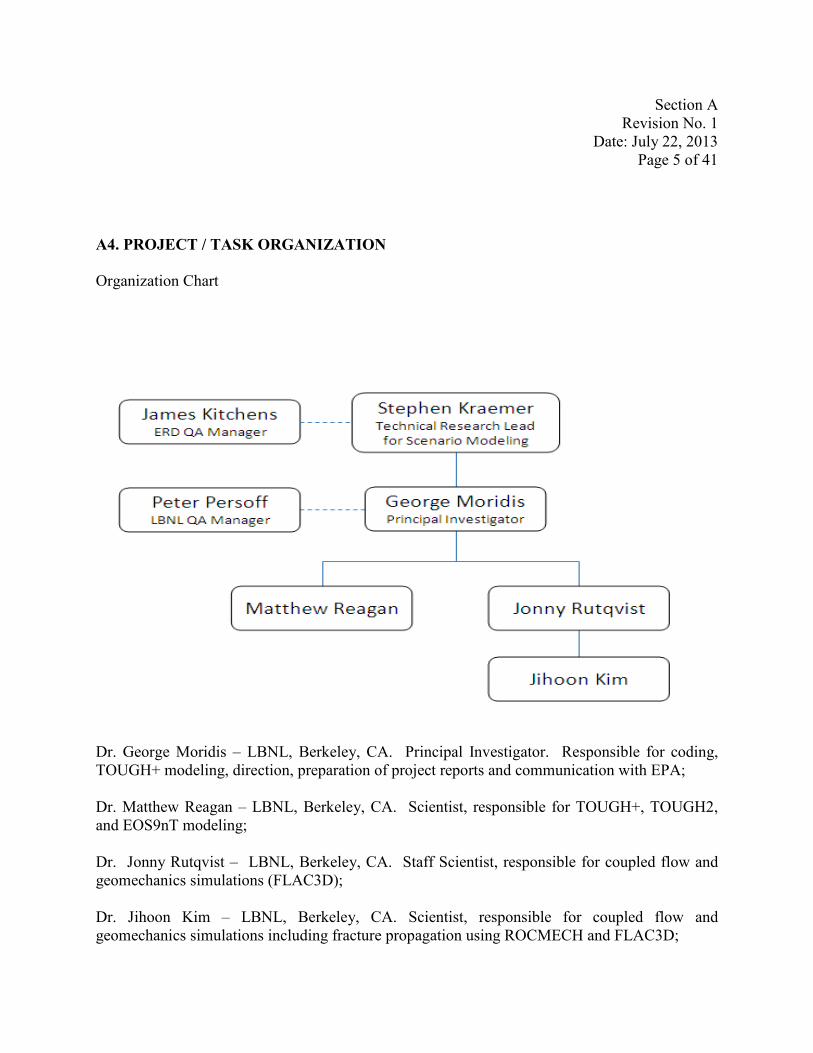
A4. PROJECT / TASK ORGANIZATION
Organization Chart
Dr. George Moridis – LBNL, Berkeley, CA. Principal Investigator. Responsible for coding, TOUGH+ modeling, direction, preparation of project reports and communication with EPA;
Dr. Matthew Reagan – LBNL, Berkeley, CA. Scientist, responsible for TOUGH+, TOUGH2, and EOS9nT modeling;
Dr. Jonny Rutqvist – LBNL, Berkeley, CA. Staff Scientist, responsible for coupled flow and geomechanics simulations (FLAC3D);
Dr. Jihoon Kim – LBNL, Berkeley, CA. Scientist, responsible for coupled flow and geomechanics simulations including fracture propagation using ROCMECH and FLAC3D;

Section A Revision No. 1
Date: July 22, 2013 Page 6 of 41
NOTE: Additional LBNL scientists may join the project, as dictated by evolving project needs. All scientists will be under the supervision of Dr. George Moridis, who is responsible for the overall project management.
Dr. Peter Persoff – LBNL, Berkeley, CA. QA Manager, responsible for preparation of QA project plan and self– assessment of QA compliance with this plan;
Mr. James Kitchens – EPA ERD, Athens, GA. EPA QA Manager, Environmental Protection Agency, Responsible for QA review/approval of the QAPP, conducting audits, and QA review/approval of the final product;
Dr. Stephen Kraemer – EPA ERD Athens, GA. EPA Project Officer for the Interagency Agreement with LBNL, and the Project Manager for the Hydraulic Fracturing Failure Scenarios assessment. Responsible for technical oversight, technical review of the QAPP, ensuring project goals are achieved, and review/approval of project deliverables;
A5. PROBLEM DEFINITION / BACKGROUND
• Background information on the problem Hydrocarbon production from tight reservoirs has grown rapidly over the last few years. Gas production from shale and tight-sand deposits has proven remarkably successful in increasing substantially both gas production and reserves estimates in the U.S. In addition to its potential financial benefits, the development of technology to produce fossil fuels in previously inaccessible domestic geologic systems is considered a substantial contributor to energy security.
The universal feature of all tight reservoirs is the unavoidable need for well and reservoir stimulation: the matrix permeability is extremely low (often at the nano-Darcy level) and, even with the presence of a system of natural fractures, it cannot support flow at anything approaching commercially viable rates without permeability enhancement. Such enhancement/stimulation is provided by a number of methods, all of which are designed to develop a new system of artificial fractures that increase the permeability of the system and increase the surface area (over which reservoir fluids flow from the matrix to the permeable fractures) to provide access to larger volume of the reservoir. Thus, stimulation techniques are the only means of rendering resource-rich but unproductive natural reservoirs into commercially viable entities. Fundamentally, it is stimulation technology that made gas and oil production from shales possible, and it is this same technology that has effected production increases of orders of magnitude over the last few years.
Conventional stimulation techniques involve the creation of a system of individual fractures

Section A Revision No. 1
Date: July 22, 2013 Page 7 of 41
emanating from particular points along the wellbore. Although it may be possible to develop additional fractures (e.g., stress release fractures), the fracture system resulting from conventional stimulation is dominated by the “main” fractures (planar or dendritic) that occur at the locations of stimulation treatment.
Conventional stimulation techniques are usually variants of hydraulic fracturing (HF) in which the near-incompressibility of liquids is exploited to deliver a shock that induces rock fracturing stemming from the target point. In this case, the artificial fracture system is induced by the injection of water or of a water-based medium into the fractures and the matrix of the geologic medium. Related techniques involve the use of explosives.
The substantial increase in gas production (and the corresponding economic benefits) derived from stimulation has been accompanied by controversy. Some of it centers on the large quantities of water needed for hydro-fracturing. However, the bulk of the controversy and environmental concern revolves around undesirable effects of stimulation to the subsurface beyond the confines of the tight, hydrocarbon-bearing formation. Generally speaking, the concerns are that reservoir stimulation creates significant environmental hazards through the creation of fast permeability pathways (e.g., via the fracturing of the overburden of reservoirs, or failure of the cement in imperfectly completed wells). This could have a significant adverse consequence of contamination of potable groundwater resources (the main source of drinking water for a large part of the US rural population) by escaping hydrocarbons and other reservoir fluids that ascend through the subsurface.
The work governed by this Quality Assurance Program Plan (QAPP) involves the investigation by means of numerical simulation of (a) the possible mechanisms of stimulation-induced overburden-failure that could lead to such upward migration of hydrocarbons, and (b) the conditions under which such scenarios are possible.
EPA applies a graded approach to all QA requirements such that process of basing the level of application of QA requirements to work is graded according to the intended use of the results and the degree of confidence needed in the quality of the results. The EPA has determined that all projects supporting the HF study shall be considered Category 1 because the research is of significant national interest.
Possible Failure Scenarios In 2012, we identified the following plausible mechanisms for the upward migration of contaminants following stimulation:
Section A Revision No. 1
Date: July 22, 2013 Page 8 of 41
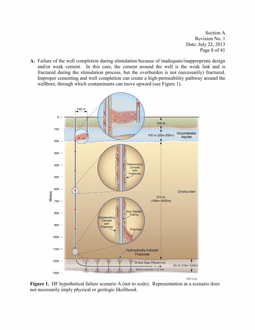
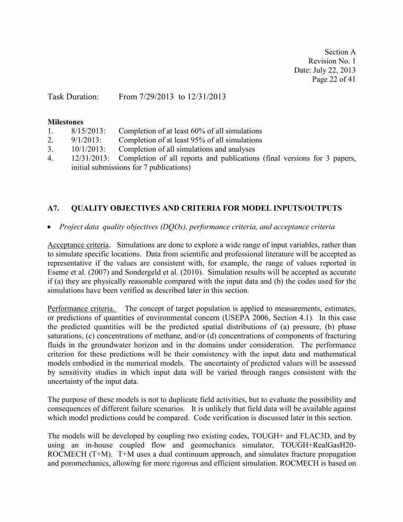
A. Failure of the well completion during stimulation because of inadequate/inappropriate design and/or weak cement. In this case, the cement around the well is the weak link and is fractured during the stimulation process, but the overburden is not (necessarily) fractured. Improper cementing and well completion can create a high-permeability pathway around the wellbore, through which contaminants can move upward (see Figure 1).
Figure 1. HF hypothetical failure scenario A (not to scale). Representation as a scenario does not necessarily imply physical or geologic likelihood.
Section A Revision No. 1
Date: July 22, 2013 Page 9 of 41
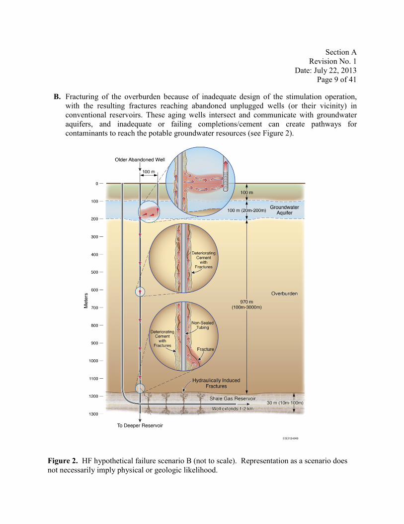
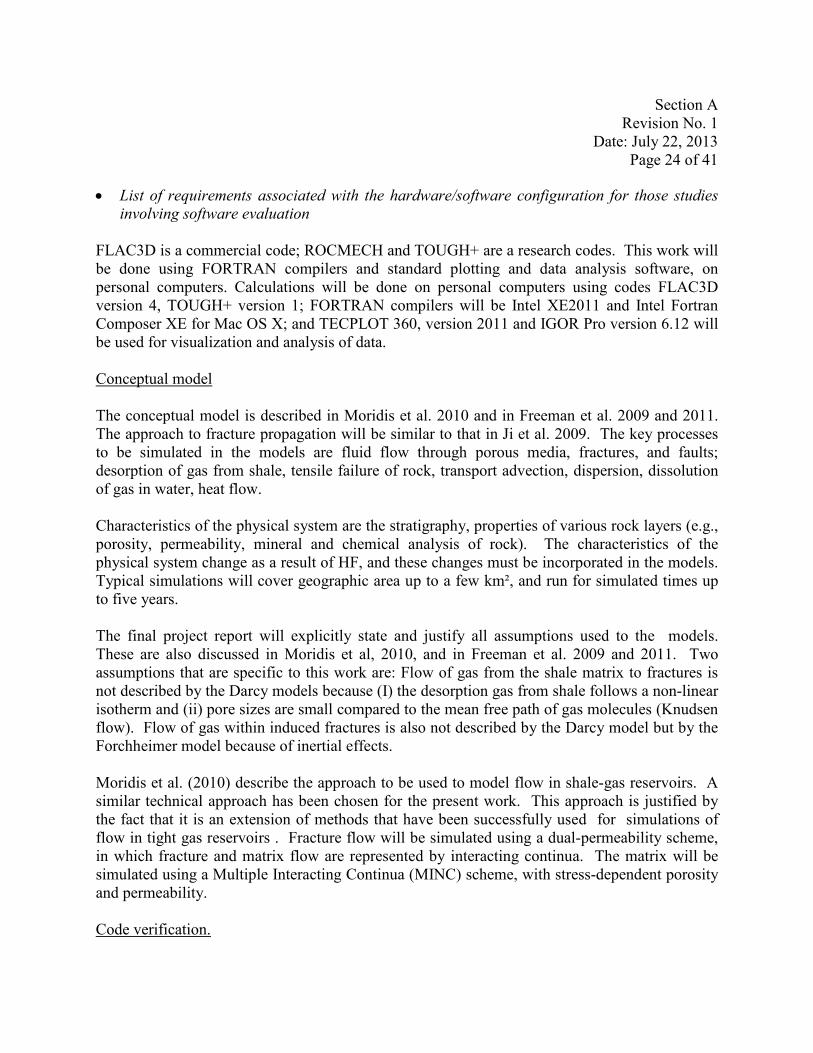
B. Fracturing of the overburden because of inadequate design of the stimulation operation, with the resulting fractures reaching abandoned unplugged wells (or their vicinity) in conventional reservoirs. These aging wells intersect and communicate with groundwater aquifers, and inadequate or failing completions/cement can create pathways for contaminants to reach the potable groundwater resources (see Figure 2).
Figure 2. HF hypothetical failure scenario B (not to scale). Representation as a scenario does not necessarily imply physical or geologic likelihood.

Section A Revision No. 1
Date: July 22, 2013 Page 10 of 41
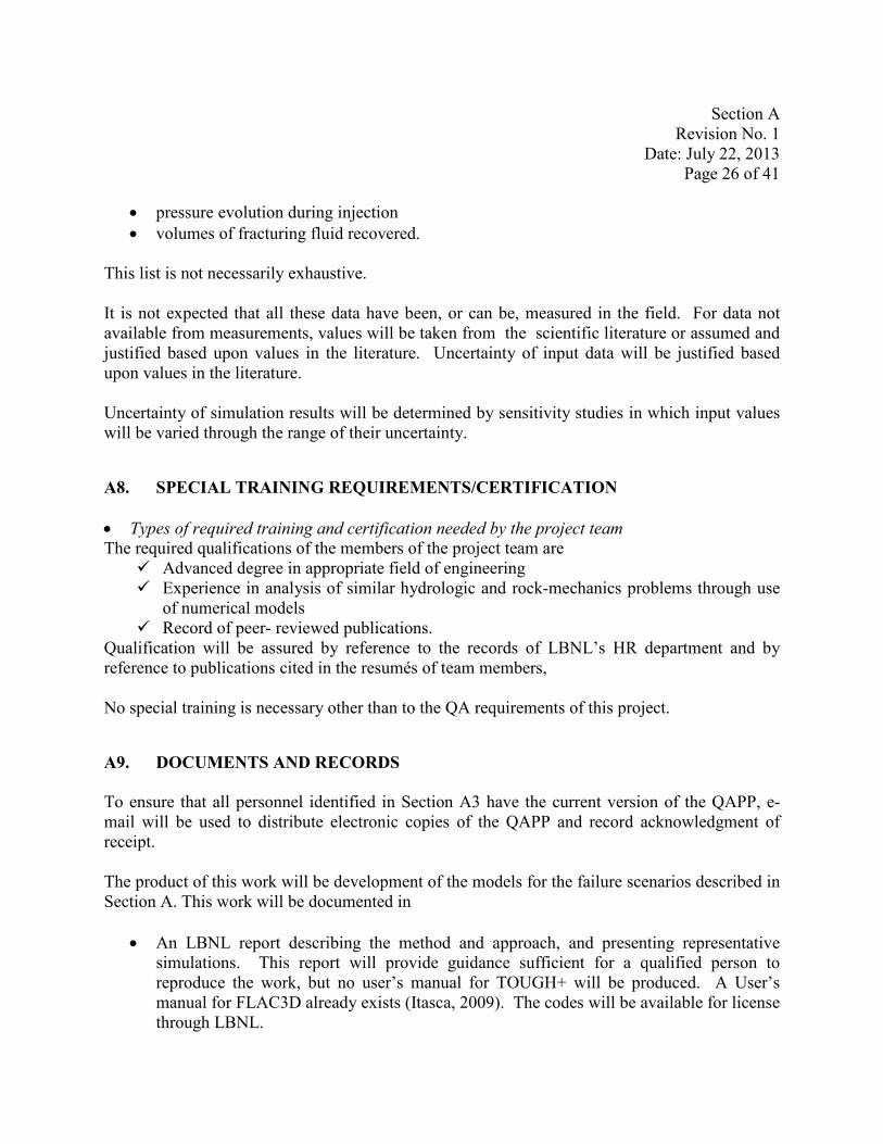
C. Fracturing of the overburden because of inadequate design of the stimulation operation, with the resulting fractures reaching groundwater resources, or even permeable formations that communicate with (generally) shallower groundwater-bearing strata (see Figure 3).
Figure 3. HF hypothetical failure scenario C (not to scale). Representation as a scenario does not necessarily imply physical or geologic likelihood.

Section A Revision No. 1
Date: July 22, 2013 Page 11 of 41
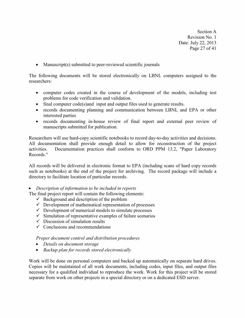
D. Induced fractures move upward and reaching groundwater resources after intercepting conventional hydrocarbon reservoirs, which may create an additional source (see Figure 4).
Figure 4. HF hypothetical failure scenario D (not to scale). Representation as a scenario does not necessarily imply physical or geologic likelihood.
Section A Revision No. 1
Date: July 22, 2013 Page 12 of 41
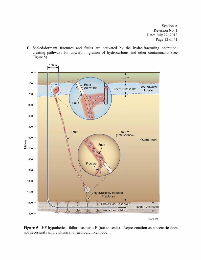
Sealed/dormant fractures and faults are activated by the hydro-fracturing operation, creating pathways for upward migration of hydrocarbons and other contaminants (see Figure 5).
E.
Figure 5. HF hypothetical failure scenario E (not to scale). Representation as a scenario does not necessarily imply physical or geologic likelihood.
Section A Revision No. 1
Date: July 22, 2013 Page 13 of 41
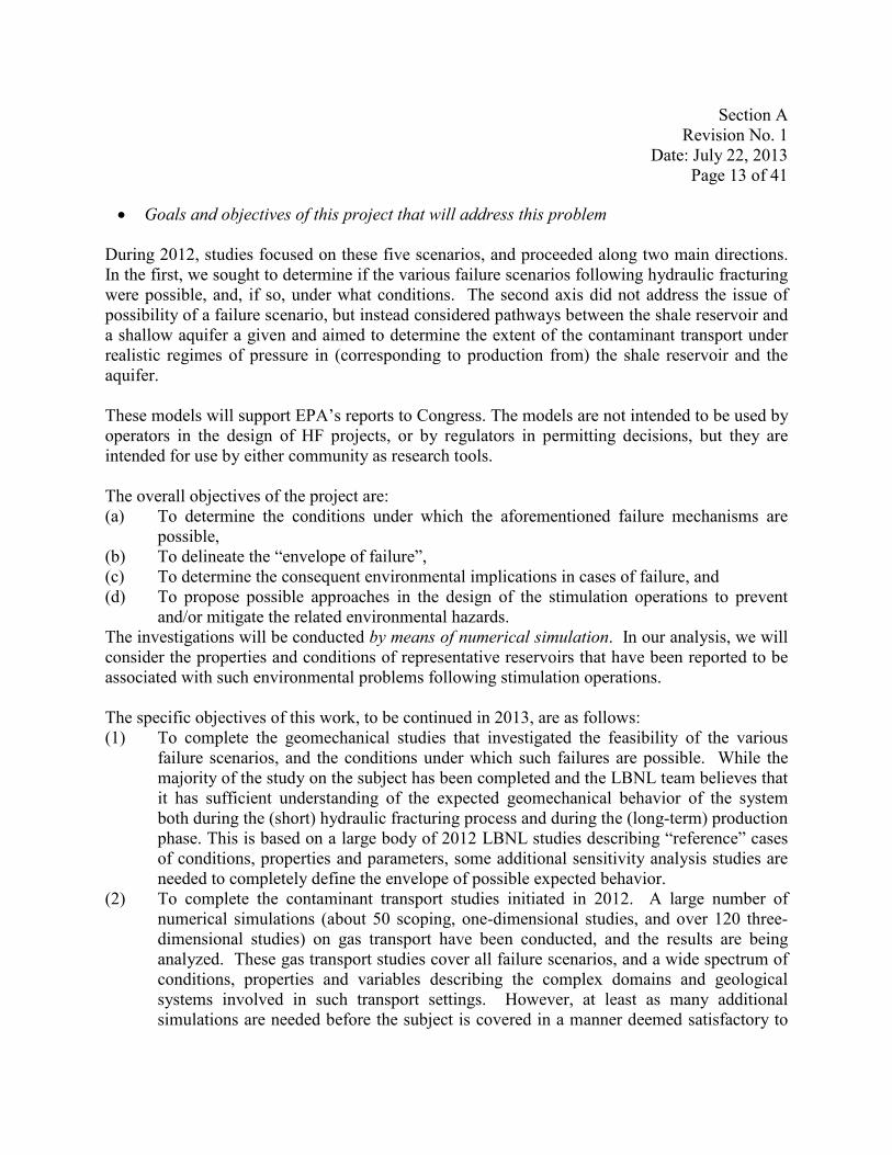
• Goals and objectives of this project that will address this problem
During 2012, studies focused on these five scenarios, and proceeded along two main directions. In the first, we sought to determine if the various failure scenarios following hydraulic fracturing were possible, and, if so, under what conditions. The second axis did not address the issue of possibility of a failure scenario, but instead considered pathways between the shale reservoir and a shallow aquifer a given and aimed to determine the extent of the contaminant transport under realistic regimes of pressure in (corresponding to production from) the shale reservoir and the aquifer.
These models will support EPA’s reports to Congress. The models are not intended to be used by operators in the design of HF projects, or by regulators in permitting decisions, but they are intended for use by either community as research tools.
The overall objectives of the project are: (a) To determine the conditions under which the aforementioned failure mechanisms are
possible, (b) To delineate the “envelope of failure”, (c) To determine the consequent environmental implications in cases of failure, and (d) To propose possible approaches in the design of the stimulation operations to prevent
and/or mitigate the related environmental hazards. The investigations will be conducted by means of numerical simulation. In our analysis, we will consider the properties and conditions of representative reservoirs that have been reported to be associated with such environmental problems following stimulation operations.
The specific objectives of this work, to be continued in 2013, are as follows: (1) To complete the geomechanical studies that investigated the feasibility of the various
failure scenarios, and the conditions under which such failures are possible. While the majority of the study on the subject has been completed and the LBNL team believes that it has sufficient understanding of the expected geomechanical behavior of the system both during the (short) hydraulic fracturing process and during the (long-term) production phase. This is based on a large body of 2012 LBNL studies describing “reference” cases of conditions, properties and parameters, some additional sensitivity analysis studies are needed to completely define the envelope of possible expected behavior.
(2) To complete the contaminant transport studies initiated in 2012. A large number of numerical simulations (about 50 scoping, one-dimensional studies, and over 120 three-dimensional studies) on gas transport have been conducted, and the results are being analyzed. These gas transport studies cover all failure scenarios, and a wide spectrum of conditions, properties and variables describing the complex domains and geological systems involved in such transport settings. However, at least as many additional simulations are needed before the subject is covered in a manner deemed satisfactory to

Section A Revision No. 1
Date: July 22, 2013 Page 14 of 41
the LBNL team. Additionally, the effort in 2013 will also cover the study of transport of dissolved contaminants, e.g., salts, brines, etc.
The models are appropriate for their intended purpose, as they can simulate the flow and transport of gas, water, and dissolved contaminants concurrently in a fractures and porous reservoir. Full qualification of TOUGH+ software is not within the scope of this project.
• Reasons the project is important, how it supports other existing research, programs, or regulations
Congress, in response to public concern, has directed the United States Environmental Protection Agency (EPA) to conduct research to examine the relationship between hydraulic fracturing and drinking water resources (USEPA, 2011a). This project will support reports that EPA is obligated to give to Congress. HF-enhanced shale gas is a significant energy resource for the United States that must be developed in a responsible manner.
• Reasons one model is determined to be better than another for this application
Though the physical situation is too complex to be represented accurately by an analytical model, the numerical models employed will couple flow, transport, thermodynamics (heat flow and phase change), and geomechanics to produce realistic simulations.
The computer codes used in this work, TOUGH+, FLAC3D, and ROCMECH, incorporate more of the relevant physical processes than any other codes. Rutqvist (2011) reviews the subject of simulating coupled thermal-hydraulic-mechanical processes in geological media. TOUGH+ has been developed, and continues in development, because of the lack of any existing model to simulate complex processes. The method of coupling of TOUGH+ with FLAC3D will be as reported in Rutqvist 2011, Rutqvist et al. 2009, and Rutqvist and Moridis 2009; the method of coupling of TOUGH+ with ROCMECH will be as reported in Kim and Moridis (2012, 2013).
A brief description of TOUGH+ and FLAC3D, and their coupling, is presented in Appendix A. Further description of ROCMECH and its coupling with TOUGH+ is presented in Section A7.
• Conflicts or uncertainties that will be resolved by this project Incidents of contamination of aquifers have been reported. The models may be used to investigate whether the claimed (and proposed) scenarios are possible and if so under what conditions.

Section A Revision No. 1
Date: July 22, 2013 Page 15 of 41
A6. PROJECT/TASK DESCRIPTION AND SCHEDULE
• Summary of all work to be performed, products to be produced, and the schedule for Implementation
The work for 2013 is organized into eight tasks as follows:
Task 1: Continuation of Expansion of the Data Base Related to Reported Environmental Problems The mathematical possibility of all the possible failure scenarios needs to be constrained by the widest possible range of realistic values of properties and conditions encountered in the tight geologic systems under investigation. Thus, in this task, we collect all available data (geological, reservoir, geophysical, geochemical, flow, geomechanical, type of environmental problem, extent of contamination, well design etc.) in cases/instances of reported problems related to stimulation operations in the US and/or Canada. Additionally, we attempt to identify cases related to all five types of geomechanical failure discussed in Section A5, and try to make the database as wide as possible. This task requires extensive interaction with federal and/or state environmental protection agencies; these are expected to provide all the available data.
Current status and planned 2013 activities: As initially designed, the Environmental Protection Agency was responsible for the collection and assembly of all these data, which was not limited to their own data collection from confirmed or suspected cases of groundwater contamination by hydro-fracturing activities in shale-gas operations, but was to include data collected by other agencies as well as data published in the peer-reviewed literature. LBNL’s role was to organize the data in the database using consistent metrics, and to identify important cases that are to be fully analyzed.
It became obvious early in the first year of the study that this task could not be completed by the initially proposed deadline of 3/31/2012 if only EPA-transmitted data were to be included. The reasons for the delay are the sparsity, limited spectrum, and the relatively poor quality of the data available to EPA for transmission to LBNL, as well as the type of some of the data (which address issues outside the scope of this study). Thus, a decision was reached early in the project to have this task open-ended, with continuing data additions to the database as they become available.
In light of the scarcity of field data from EPA, in the 2nd year of the project we plan to continue the approach established in 2012: LBNL will continue to conduct throughout the duration of the project an extensive literature review effort, collecting all published data related to case studies

Section A Revision No. 1
Date: July 22, 2013 Page 16 of 41
of hydraulic fracturing of shales. All these literature-originating data are evaluated and their useful attributes are to be added to the database, which will be made available to all interested parties (EPA has already access to them).
Task Duration: From 7/29/2013 to 12/31/2013
Task 2: Analysis of Consequences of Geomechanical Wellbore Failure (Scenario A, Figure 1) This task focuses on the flow and geomechanical processes involved in the failure of the well completion (mainly cementing) during the stimulation process. Such a failure can allow escaping hydrocarbons to ascend through the damaged annular space around the wellbore to reach vulnerable groundwater resources. This task aims to determine (a) the well design properties, variables and conditions that can lead to such failures when exposed to the pressures that develop during stimulation operations, (b) the possible length of the failed zone along the wellbore, and the likelihood that the fractured cement can extend over long distances (if the tight formation and the groundwater are separated by considerable distances) from the stimulation point, (c) the short- and long-term environmental effect of such failure of the near-wellbore zone during hydrocarbon production and after a well shut-down, and (d) sensitivity to factors affecting items (a) through (c).
Current status and planned 2013 activities: The majority of the relevant geomechanical studies (involving cement failure and fracture propagation into the shale and the overburden) has been completed, and publications on the subject have been submitted to peer-review (see Task 8). Several very complex 3D grids (describing a range of settings) have been developed, and over 60 simulations that cover a wide spectrum of possible variations of the problem of gas transport from the shale reservoir to a shallow aquifer have been completed. A thorough description of progress and activities in this task can be found in the 2012 Project Year-End Report that was submitted to EPA in November 2012.
For 2013, planned activities are: (a) To complete the geomechanical studies related to this task, including the study of fracture
creation and propagation exclusively within the cement and sensitivity analyses studies related to both this and the 2012 studies,
(b) To complete the study of the gas transport studies that begun in 2012 by analyzing the data collected thus far, and the data from new simulations that may be deemed necessary
(c) To study the problem of transport of dissolved contaminants (e.g., salts, organics, etc.) from the shale reservoir to a shallow aquifer
Task Duration: From 7/29/2013 to 8/31/2013
Section A Revision No. 1
Date: July 22, 2013 Page 17 of 41
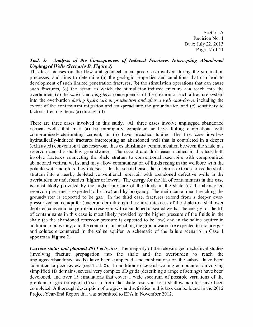
Task 3: Analysis of the Consequences of Induced Fractures Intercepting Abandoned Unplugged Wells (Scenario B, Figure 2) This task focuses on the flow and geomechanical processes involved during the stimulation processes, and aims to determine (a) the geologic properties and conditions that can lead to development of such limited penetration fractures, (b) the stimulation operations that can cause such fractures, (c) the extent to which the stimulation-induced fracture can reach into the overburden, (d) the short- and long-term consequences of the creation of such a fracture system into the overburden during hydrocarbon production and after a well shut-down, including the extent of the contaminant migration and its spread into the groundwater, and (e) sensitivity to factors affecting items (a) through (d).
There are three cases involved in this study. All three cases involve unplugged abandoned vertical wells that may (a) be improperly completed or have failing completions with compromised/deteriorating cement, or (b) have breached tubing. The first case involves hydraulically-induced fractures intercepting an abandoned well that is completed in a deeper (exhausted) conventional gas reservoir, thus establishing a communication between the shale gas reservoir and the shallow groundwater. The second and third cases studied in this task both involve fractures connecting the shale stratum to conventional reservoirs with compromised abandoned vertical wells, and may allow communication of fluids rising in the wellbore with the potable water aquifers they intersect. In the second case, the fractures extend across the shale stratum into a nearby-depleted conventional reservoir with abandoned defective wells in the overburden or underburden (higher or lower). The energy for the lift of contaminants in this case is most likely provided by the higher pressure of the fluids in the shale (as the abandoned reservoir pressure is expected to be low) and by buoyancy. The main contaminant reaching the groundwater is expected to be gas. In the third case, fractures extend from a deeper over-pressurized saline aquifer (underburden) through the entire thickness of the shale to a shallower depleted conventional petroleum reservoir with abandoned unsealed wells. The energy for the lift of contaminants in this case is most likely provided by the higher pressure of the fluids in the shale (as the abandoned reservoir pressure is expected to be low) and in the saline aquifer in addition to buoyancy, and the contaminants reaching the groundwater are expected to include gas and solutes encountered in the saline aquifer. A schematic of the failure scenario in Case 1 appears in Figure 2.
Current status and planned 2013 activities: The majority of the relevant geomechanical studies (involving fracture propagation into the shale and the overburden to reach the unplugged/abandoned wells) have been completed, and publications on the subject have been submitted to peer-review (see Task 8). In addition to several scoping computations involving simplified 1D domains, several very complex 3D grids (describing a range of settings) have been developed, and over 15 simulations that cover a wide spectrum of possible variations of the problem of gas transport (Case 1) from the shale reservoir to a shallow aquifer have been completed. A thorough description of progress and activities in this task can be found in the 2012 Project Year-End Report that was submitted to EPA in November 2012.
Section A Revision No. 1
Date: July 22, 2013 Page 18 of 41
For 2013, planned activities include: (a) To conduct the relatively minor additional studies needed to complete the geomechanical
component of this task, including the revision/modification of publications already submitted to peer-reviewed journals,
(b) To complete the study of the gas transport studies in Case 1 that begun in 2012 by analyzing the data collected thus far, and the data from new simulations that may be deemed necessary
(c) To prepare a report documenting the results of gas transport studies in Cases 2 and 3 (d) To prepare a report documenting the results of a study of transport of dissolved
contaminants (e.g., salts, organics, etc.) from the shale reservoir to a shallow aquifer in Cases 1, 2 and 3
Task Duration: From 7/29/2013 to 10/31/2013
Task 4: Analysis of the Consequences of Induced Fractures Reaching Groundwater Resources (Scenario C, Figure 3)
This task focuses on the flow and geomechanical processes involved during the stimulation processes, and aims to determine (a) the geologic properties and conditions that can lead to induced fractures reaching groundwater resources, (b) the stimulation operations that can cause extensive fracturing of the overburden, (c) the extent to which the stimulation-induced fracture can reach into the overburden, (d) the short- and long-term consequences of the creation of such an unwanted extensive fracture system into the overburden during hydrocarbon production and after a well shut-down, including the extent of the contaminant migration and its spread into the groundwater, and (e) sensitivity to factors affecting items (a) through (d). The mathematical possibility of all these cases will be constrained by the widest possible range of realistic values of properties and conditions encountered in the tight geologic systems under investigation.
NOTE: Because of their similarities, the planned activities for 2013 in Tasks 4 and 5 will be discussed together in Task 5
Task 5: Analysis of Consequences of Induced Fractures Reaching Groundwater Resources After Intercepting Conventional Reservoirs (Scenario D, Figure 4)
Task 5 investigates the results of stimulation-induced fractures intercepting conventional reservoirs (overlying or underlying). In a certain sense, this task is an extension of Task 4, as a fracture system extending deep into the overburden and reaching into the groundwater is a requirement for this issue to be a potential environmental problem. Obviously, the flow regime in this case can be different from that of Task 4 because the system highly permeable fractures
Section A Revision No. 1
Date: July 22, 2013 Page 19 of 41
are now charged not only with the hydrocarbons that are very slowly released from the matrix of the tight system, but also from the much more permeable conventional reservoirs. Thus, fracture storage is no longer a limitation because the fractures are recharged from the permeable conventional reservoir. Current status and planned 2013 activities: The majority of the relevant geomechanical studies in Tasks 4 and 5 (nearly identical, and involving fracture propagation into the shale and the overburden to reach the shallow aquifer) has been completed, and publications on the subject have been submitted to peer-review (see Task 8). In addition to extensive scoping computations involving simplified 1D domains, several very complex 3D grids (describing a range of settings) have been developed, and over 60 simulations that cover a wide spectrum of possible variations of the problem of gas transport (Tasks 4 and 5) from the shale reservoir to a shallow aquifer have been completed. A thorough description of progress and activities in these tasks can be found in the 2012 Project Year-End Report that was submitted to EPA in November 2012.
For 2013, in the planned activities for Tasks 4 and 5 are: (a) To conduct the relatively minor additional studies needed to complete the geomechanical
component of these tasks (mainly involving sensitivity analyses), including the revision/modification of publications already submitted to peer-reviewed journals,
(b) To complete the study of the gas transport studies that begun in 2012 by analyzing the data collected thus far, and the data from new simulations that may be deemed necessary,
(c) To prepare a report documenting the results of a study of the problem of transport of dissolved contaminants (e.g., salts, organics, etc.) from the shale reservoir to a shallow aquifer
Task Duration: From 7/29/2013 to 9/30/2013
Task 6: Analysis of Consequences of Activation of Native Faults and Fractures (Scenario E, Figure 5)
This task focuses on the flow and geomechanical processes involved in the response of native fractures and faults to the stimulation process. This task aims to determine (a) the geomechanical conditions (both in terms of system properties and stimulation practices) under which the displacement of the subsurface during stimulation is a reversible process (with the system returning to its original state after the end of stimulation), (b) the effect of displacement on the native fracture and fault aperture and permeability, (c) the short- and long-term transport effect of communication of induced fractures with native fractures and faults (in terms of the reach into the overburden) during hydrocarbon production and after a well shut-down, (c) the short- and long-term groundwater pollution that escaping reservoir fluids can cause under this scenario, and (d) sensitivity to factors affecting items (a) through (c).
A particular case that will be investigated in this Task is an extension of the study in Task 3, and involves the possibility of activated native faults or fractures reaching abandoned unsealed wells
Section A Revision No. 1
Date: July 22, 2013 Page 20 of 41
with failing completions in conventional reservoirs.
Current status and planned 2013 activities: The majority of the relevant geomechanical studies (involving fault activation and induced seismicity) have been completed, and publications on the subject have been submitted to peer-review (see Task 8). The solute transport studies related to this failure scenario are easily covered (and are represented) by the studies in Tasks 3, 4 and 5. A thorough description of progress and activities in this task can be found in the 2012 Project Year-End Report that was submitted to EPA in November 2012.
For 2013, in Task 6 we plan to conduct the relatively minor additional studies needed to complete the geomechanical component of these tasks (mainly involving sensitivity analyses), including the revision/modification of publications already submitted to peer-reviewed journals.
Task Duration: From 7/29/2013 to 8/31/2013
NOTE: In Tasks 2 to 6, the analysis of groundwater contamination and its transport will not be limited to methane, but, as appropriate by the investigated scenario, will also include salinity, naturally occurring radioactive materials, and total dissolved solids (reflecting brines and contaminant-laden deeper water rising to potable water aquifers through fractures, faults, imperfectly completed wellbores, and compromised abandoned wells).
Task 7: Implementation of the QA Program This task involves the continuation of the Quality Assurance (QA) program that was implemented in (and governed the research activities of) 2012. The scope of the QAPP has been revised to govern the present work for 2013; the same controls are in place as for 2012. If changes and modifications are deemed to be necessary, these will be agreed upon and implemented after discussions between LBNL and EPA. Because of the possibility of activity on this task at any time, its duration will cover the entire 2013 period.
Task Duration: From 7/29/2013 to 12/31/2013
Task 8: Reporting
This task involves the submission of (a) monthly e-mail progress reports, (b) an interim report on 8/1/2013, and (c) a final project report (on 12/31/2013) that describes all the 2013 activities and investigations conducted within the project. This task also includes the (d) modification and revision of three publications currently in review by refereed journals, and (e) completion and submission to peer-reviewed journals of a minimum of seven manuscripts that are currently in development. The list of all publications, accepted, in review, and in development is as follows:

Section A Revision No. 1
Date: July 22, 2013 Page 21 of 41
1. Gas Flow Tightly Coupled to Elastoplastic Geomechanics for Tight and Shale Gas Reservoirs: Material Failure and Enhanced Permeability, Kim J., and G.J. Moridis, SPE Paper 155640, Proceedings, Americas Unconventional Resources Conference, 5-6 June 2012, Pittsburgh, Pennsylvania (in review)
2. A Three-Dimensional Voronoi Mesh Building Tool for the TOUGH Family Of Codes, by M. Freeman, O. Olorode and K. Boyle-Freeman, to be submitted to “Computers and Geosciences” (presented at the 2012 TOUGH Symposium; an expanded version is currently in development for submission to “Computers and Geosciences”)
3. The RealGas and RealGasH2O Modules of the TOUGH+ Code for the Simulation of Coupled Fluid and Heat Flow in Tight/Shale Gas Systems, by G.J. Moridis and C.M. Freeman (presented at the 2012 TOUGH Symposium; currently in review for publication in “Computers and Geosciences”)
4. The RealGasH2OCont Module of the TOUGH+ Code for the Simulation of Coupled Fluid and Heat Flow, and Contaminant Transport, in Tight/Shale Gas Systems, by G.J. Moridis and C.M. Freeman (in preparation, to be submitted to “Computers and Geosciences”)
5. Development Of The T+M Coupled Flow-Geomechanical Simulator To Describe Fracture Propagation And Coupled Flow-Thermal-Geomechanical Processes In Tight/Shale Gas Systems, by J. Kim and G.J. Moridis, Computers and Geosciences, in press 2013.
6. Analysis of Fracture Propagation During Hydraulic Fracturing Operations in Tight/Shale Gas Systems, by J. Kim and G.J. Moridis, to be submitted to either the “Journal of Geophysical Research” or the “SPE Journal” or the “Journal of Petroleum Science and Engineering”
7. Analysis of Geomechanical Failure of Well Cement and Fracture Propagation During Hydraulic Fracturing Operations in Tight/Shale Gas Systems, by J. Kim and G.J. Moridis, to be submitted to either the “SPE Journal” or the “Journal of Petroleum Science and Engineering”
8. Gas Migration from a Tight/Shale Gas Reservoir to an Overlying Aquifer Through Fractures and Other Fast Pathways, by G.J. Moridis and M. Freeman, in development, to be submitted to either “Water Resources Research” or the “Journal of Geophysical Research” or the “SPE Journal” or another appropriate journal
9. Contaminant Transport from a Tight/Shale Gas Reservoir to an Overlying Aquifer Through Fractures and Other Fast Pathways, by G.J. Moridis and M. Freeman, in development, to be submitted to either “Water Resources Research” or the “Journal of Geophysical Research” or the “SPE Journal” or another appropriate journal
10. Modeling of Fault Reactivation and Induced Seismicity During Hydraulic Fracturing of Shale-Gas Reservoirs, by J. Rutqvist, A. Rinaldi, F. Cappa, and G.J. Moridis Journal of Petroleum Science and Engineering Volume 107, July 2013, Pages 31–44, http://www.sciencedirect.com/science/article/pii/S0920410513001241
Section A Revision No. 1
Date: July 22, 2013 Page 22 of 41
Task Duration: From 7/29/2013 to 12/31/2013
Milestones 1. 8/15/2013: Completion of at least 60% of all simulations 2. 9/1/2013: Completion of at least 95% of all simulations 3. 10/1/2013: Completion of all simulations and analyses 4. 12/31/2013: Completion of all reports and publications (final versions for 3 papers,
initial submissions for 7 publications)
A7. QUALITY OBJECTIVES AND CRITERIA FOR MODEL INPUTS/OUTPUTS
• Project data quality objectives (DQOs), performance criteria, and acceptance criteria
Acceptance criteria. Simulations are done to explore a wide range of input variables, rather than to simulate specific locations. Data from scientific and professional literature will be accepted as representative if the values are consistent with, for example, the range of values reported in Eseme et al. (2007) and Sondergeld et al. (2010). Simulation results will be accepted as accurate if (a) they are physically reasonable compared with the input data and (b) the codes used for the simulations have been verified as described later in this section.
Performance criteria. The concept of target population is applied to measurements, estimates, or predictions of quantities of environmental concern (USEPA 2006, Section 4.1). In this case the predicted quantities will be the predicted spatial distributions of (a) pressure, (b) phase saturations, (c) concentrations of methane, and/or (d) concentrations of components of fracturing fluids in the groundwater horizon and in the domains under consideration. The performance criterion for these predictions will be their consistency with the input data and mathematical models embodied in the numerical models. The uncertainty of predicted values will be assessed by sensitivity studies in which input data will be varied through ranges consistent with the uncertainty of the input data.
The purpose of these models is not to duplicate field activities, but to evaluate the possibility and consequences of different failure scenarios. It is unlikely that field data will be available against which model predictions could be compared. Code verification is discussed later in this section.
The models will be developed by coupling two existing codes, TOUGH+ and FLAC3D, and by using an in-house coupled flow and geomechanics simulator, TOUGH+RealGasH20ROCMECH (T+M). T+M uses a dual continuum approach, and simulates fracture propagation and poromechanics, allowing for more rigorous and efficient simulation. ROCMECH is based on

Section A Revision No. 1
Date: July 22, 2013 Page 23 of 41
the finite element method, whereas FLAC3D is upon the explicit finite difference method.
FLAC3D and the TOUGH family of codes have been verified and validated and used in nuclear waste applications with stringent quality requirements. TOUGH+ is a research code; therefore the user of the code is responsible to confirm its proper use and operation. Earlier versions of TOUGH+ are available for distribution; as distributed it is supplied with test problems that the user can run to verify proper installation.
T+M has been verified by comparison of its results with analytical solutions, and used to simulate coupled thermal-hydraulic-mechanical processes in geological media (Kim and Moridis (2012, 2013). T+M continues in development, along with TOUGH+ and FLAC3D. The method of coupling of TOUGH+RealGasH20-ROCMECH was reported in Kim and Moridis (2012, 2013).
The versions of TOUGH+ and ROCMECH developed for this project will be available to EPA and ready for scrutiny by the EPA or any Federal agency. Test problems and simulation results will be provided. No user’s manual will be provided, but the project reports and the code itself will provide adequate documentation for a knowledgeable user. Test problems will be run during development; input and output files and uncompiled code will be provided.
Model calibration is a process of adjusting model inputs so that predicted values match observations. Generally these models will be used to simulate the failure scenarios identified in Section A5. If sufficient information on the geological system become available that permit comparison of measured and predicted data, then model(s) will be calibrated, but it is not expected that any such data will be available.
Uncertainty and variability will be assessed by sensitivity analyses in which the important input parameters will be varied and their effects determined. All significant input data that can reasonably be expected to affect the results will be varied through a range of expected or typical values. One variable will be varied and others held constant, and results will be presented as plots of specific output values vs. varied input, other inputs having been held constant.
• Description of task that needs to be addressed and the intended uses of the output of the modeling project to achieve the task
The task to be addressed is to determine the range of conditions that can lead to overburden failure and associated environmental degradation. The intended use of the output of the modeling project is to support EPA’s report to Congress. These models may in the future be used to evaluate proposed HF projects to ensure that such unintended consequences are avoided.
Section A Revision No. 1
Date: July 22, 2013 Page 24 of 41
• List of requirements associated with the hardware/software configuration for those studies involving software evaluation
FLAC3D is a commercial code; ROCMECH and TOUGH+ are a research codes. This work will be done using FORTRAN compilers and standard plotting and data analysis software, on personal computers. Calculations will be done on personal computers using codes FLAC3D version 4, TOUGH+ version 1; FORTRAN compilers will be Intel XE2011 and Intel Fortran Composer XE for Mac OS X; and TECPLOT 360, version 2011 and IGOR Pro version 6.12 will be used for visualization and analysis of data.
Conceptual model
The conceptual model is described in Moridis et al. 2010 and in Freeman et al. 2009 and 2011. The approach to fracture propagation will be similar to that in Ji et al. 2009. The key processes to be simulated in the models are fluid flow through porous media, fractures, and faults; desorption of gas from shale, tensile failure of rock, transport advection, dispersion, dissolution of gas in water, heat flow.
Characteristics of the physical system are the stratigraphy, properties of various rock layers (e.g., porosity, permeability, mineral and chemical analysis of rock). The characteristics of the physical system change as a result of HF, and these changes must be incorporated in the models. Typical simulations will cover geographic area up to a few km², and run for simulated times up to five years.
The final project report will explicitly state and justify all assumptions used to the models. These are also discussed in Moridis et al, 2010, and in Freeman et al. 2009 and 2011. Two assumptions that are specific to this work are: Flow of gas from the shale matrix to fractures is not described by the Darcy models because (I) the desorption gas from shale follows a non-linear isotherm and (ii) pore sizes are small compared to the mean free path of gas molecules (Knudsen flow). Flow of gas within induced fractures is also not described by the Darcy model but by the Forchheimer model because of inertial effects.
Moridis et al. (2010) describe the approach to be used to model flow in shale-gas reservoirs. A similar technical approach has been chosen for the present work. This approach is justified by the fact that it is an extension of methods that have been successfully used for simulations of flow in tight gas reservoirs . Fracture flow will be simulated using a dual-permeability scheme, in which fracture and matrix flow are represented by interacting continua. The matrix will be simulated using a Multiple Interacting Continua (MINC) scheme, with stress-dependent porosity and permeability.
Code verification.

Section A Revision No. 1
Date: July 22, 2013 Page 25 of 41
The logic and structure of the codes will be documented in the code itself using comment lines, and in the final report. The logic and structure of FLAC3D and TOUGH+ have been described in their respective user’s manuals (Itasca, 2009, Moridis et al. 2008). No other software or model exists that can be used to simulate the complex processes in the failure scenarios described in Section A5. To verify that the TOUGH+ code is correctly solves the mathematical model, solutions to three simplified problems simulated with TOUGH+ were compared with analytical solutions as reported in the Appendix A1 of the final report for 2012; agreement was within 1%. Additional verification as necessary may be done by comparison to simulations with EOS9nT (Moridis et al. 1998), or, where possible, to an analytical solution. EOS9nT has been qualified for use in the contaminant transport studies in support of the license application for the High-Level Nuclear Waste Repository in the unsaturated zone of Yucca Mountain, Nevada. Representative results of these simulations can be found in Moridis et al. (2003), Moridis and Seol (2006a;b) and Seol and Moridis (2006). Moridis et al. (1998) is the user’s manual for EOS9nT and contains several test problems demonstrating agreement with analytical and semi-analytical solutions, and Bechtel SAIC Corporation, (2004) provides traceability the software qualification for the Yucca Mountain License Application.
FLAC3D is a commercial code and a user’s manual, which includes several verification problems with comparison with analytical solutions, is available (Itasca 2009). The code TOUGH+ is a research code and no user’s manual will be prepared. Documentation will be adequate to allow a qualified person to reproduce the work or to run new problems, but a final user’s manual will not be prepared. TOUGH+ is a research code; therefore the user of the code is responsible to confirm its proper use. As distributed it is with supplied with test problems that the user can run to verify proper installation and operation. Note that the TOUGH family of codes has been extensively documented (Moridis et al. 2008, Zhang et al. 2008) and much of that documentation is also relevant to TOUGH+.
Input data required for these simulations will be obtained from the EPA and obtained from the technical and scientific literature. Input data include: • site stratigraphy • rock properties (grain density, intrinsic matrix permeability, permeability of natural
fracture network, matrix and fracture porosity, fracture spacing and aperture) • initial conditions (fracture and matric saturation, pressures) • gas composition • pore water composition • gas adsorption isotherm • thermal conductivity and specific heat of rocks • parameters for van Genuchten model of relative permeability • fracturing pressure • number of stages • injected volumes
Section A Revision No. 1
Date: July 22, 2013 Page 26 of 41
• pressure evolution during injection • volumes of fracturing fluid recovered.
This list is not necessarily exhaustive.
It is not expected that all these data have been, or can be, measured in the field. For data not available from measurements, values will be taken from the scientific literature or assumed and justified based upon values in the literature. Uncertainty of input data will be justified based upon values in the literature.
Uncertainty of simulation results will be determined by sensitivity studies in which input values will be varied through the range of their uncertainty.
A8. SPECIAL TRAINING REQUIREMENTS/CERTIFICATION
• Types of required training and certification needed by the project team The required qualifications of the members of the project team are Advanced degree in appropriate field of engineering Experience in analysis of similar hydrologic and rock-mechanics problems through use
of numerical models Record of peer- reviewed publications.
Qualification will be assured by reference to the records of LBNL’s HR department and by reference to publications cited in the resumés of team members,
No special training is necessary other than to the QA requirements of this project.
A9. DOCUMENTS AND RECORDS
To ensure that all personnel identified in Section A3 have the current version of the QAPP, e-mail will be used to distribute electronic copies of the QAPP and record acknowledgment of receipt.
The product of this work will be development of the models for the failure scenarios described in Section A. This work will be documented in
• An LBNL report describing the method and approach, and presenting representative simulations. This report will provide guidance sufficient for a qualified person to reproduce the work, but no user’s manual for TOUGH+ will be produced. A User’s manual for FLAC3D already exists (Itasca, 2009). The codes will be available for license through LBNL.
Section A Revision No. 1
Date: July 22, 2013 Page 27 of 41
• Manuscript(s) submitted to peer-reviewed scientific journals
The following documents will be stored electronically on LBNL computers assigned to the researchers:
• computer codes created in the course of development of the models, including test problems for code verification and validation.
• final computer code(s)and input and output files used to generate results. • records documenting planning and communication between LBNL and EPA or other
interested parties • records documenting in-house review of final report and external peer review of
manuscripts submitted for publication.
Researchers will use hard-copy scientific notebooks to record day-to-day activities and decisions. All documentation shall provide enough detail to allow for reconstruction of the project activities. Documentation practices shall conform to ORD PPM 13.2, "Paper Laboratory Records."
All records will be delivered in electronic format to EPA (including scans of hard copy records such as notebooks) at the end of the project for archiving. The record package will include a directory to facilitate location of particular records.
• Description of information to be included in reports The final project report will contain the following elements: Background and description of the problem Development of mathematical representation of processes Development of numerical models to simulate processes Simulation of representative examples of failure scenarios Discussion of simulation results Conclusions and recommendations
Proper document control and distribution procedures • Details on document storage • Backup plan for records stored electronically
Work will be done on personal computers and backed up automatically on separate hard drives. Copies will be maintained of all work documents, including codes, input files, and output files necessary for a qualified individual to reproduce the work. Work for this project will be stored separate from work on other projects in a special directory or on a dedicated ESD server.
Section A Revision No. 1
Date: July 22, 2013 Page 28 of 41
• Description of the change control process (who approves changes, etc.) Any change to this QAPP will be approved by the Principal Investigator, EPA Technical Lead and EPA QA Manager. The revised QAPP will be distributed to all participants identified in Section A3.
• Length of retention periods for each record All records will be delivered in electronic format to EPA (including scans of hard copy records such as notebooks) at the end of the project for archiving. The record package will include a directory to facilitate location of particular records. Records will be retained by EPA for a length of time to be determined by the EPA.
• Data assessment reports, interim project progress reports Interim project progress reports will be submitted to EPA as requested by the EPA project manager. Some of these reports may support EPA’s report to Congress.
• Model science formulation report, peer review reports The model science formulation will be documented in the final project report and in manuscript(s) submitted to peer-reviewed scientific journals.
Section B Revision No. 1
Date: July 2013 Page 29 of 41
B. MEASUREMENT AND DATA ACQUISITION
B1. SAMPLING PROCESS DESIGN This project includes no sampling. This section is not applicable.
B2. SAMPLING METHODS This project includes no sampling. This section is not applicable.
B3. SAMPLE HANDLING AND CUSTODY This project includes no sampling. This section is not applicable.
B4. ANALYTICAL METHODS This project includes no analysis of samples. This section is not applicable.
B5. QUALITY CONTROL This project includes no direct measurement or data acquisition. This section is not applicable.
B6. INSTRUMENT/EQUIPMENT TESTING, INSPECTION, AND MAINTENANCE This project will use no measurement or test equipment. This section is not applicable.
B7. INSTRUMENT/EQUIPMENT CALIBRATION This project includes no measurement or test equipment. This section is not applicable.
B8. INSPECTION/ACCEPTANCE OF SUPPLIES AND CONSUMABLES This project will use no supplies or consumables. This section is not applicable.
B9. NON-DIRECT MEASUREMENTS (DATA ACQUISITION REQUIREMENTS)
Input data for the models will be acquired from the EPA and from scientific literature. This project will not use any measuring or test equipment.
B10. DATA MANAGEMENT AND HARDWARE/SOFTWARE CONFIGURATION
The following data (including computer codes and input and output files) will be managed by this project:
Section C Revision No. 1
Date: July 2013 Page 30 of 41
DATA Environmental and process data will be acquired from the EPA or from the scientific literature. Data from both these sources will be accepted as accurate for use on this project. Accurate transcription of these data into input files will be verified by line-by-line hand checking (direct comparison of input files with the source data).
SOFTWARE Code verification Code verification is discussed in Section A7.
Version control Each modification of the software need not be archived, but each version that will be documented in the project reports and considered for release will be assigned a unique version number and archived.
C. ASSESSMENT AND OVERSIGHT
C1. ASSESSMENTS AND RESPONSE ACTIONS
Plans for science and product peer review
The final project report to EPA, and LBNL reports(s) will be peer reviewed as a matter of LBNL policy (LBNL 2008). Manuscript(s) will be submitted to peer-reviewed journals and presented at technical conferences.
Audit
A Technical Systems Audit (TSA) will be conducted on site by the EPA Quality Assurance Manager. Detailed checklists, based on the procedures and requirements specified in this QAPP will be prepared and used during the audit. An initial on-site TSA audit was conducted by Mr. Jim Kitchens on February 29, 2012.
C2. REPORTS TO MANAGEMENT
Monthly progress reports and a final report will be submitted to EPA. Interim reports will be submitted to EPA upon request from the EPA Technical Lead for use as input to EPA’s reports to Congress.
Section D Revision No. 1
Date: July 2013 Page 31 of 41
D. DATA VALIDATION AND USABILITY
Environmental and process data will be acquired from the EPA or from the scientific literature. Data from both these sources will be evaluated for use on this project. Attributes to be considered for acceptance will include whether the data were collected (i) using standard methods, (ii) according to approved procedures, and (iii) under a QA program. It is to be expected that available data may not be sufficient to meet the input requirements of the models; in such cases reasonable values will be assumed and justified.
D.2 Validation methods
Model components such as theory and mathematical and numerical procedures will be validated by technical review. To a great extent, the theory and mathematical and numerical procedures used in these codes have already been validated by technical review, peer review, and acceptance by the scientific community. Code verification will be conducted whereby the numerical solutions will be compared to analytical (exact) solutions. Outputs of simulations are not guarantees but are reasonable expectations, based upon the quality of input data, and uncertainty estimated from sensitivity of outputs to uncertainty of inputs. Limitations on the use of outputs of simulations will be documented and discussed in the reports.
D.3 Reconciliation with User Requirements
The project interim and final reports will describe and justify any deviations from this plan, and will include documentation and discussion of results, and will discuss limitations of the use of output data for users of the report.

References Revision No. 1
Date: July 2013 Page 32 of 41
REFERENCES
Bechtel-SAIC Corporation, 2004. Radionuclide Transport Models Under Ambient Conditions, MDL-NBS-HS-000008, REV 02, available on line at www,osti.gov/bridge/servlets/purl/8412519mVrM7/841251.pdf
Eseme E., Urai J.L., Krooss B.M., and Littke R. 2007. Review of mechanical properties of oil shales: Implications for exploitation and basin modeling. Oil Shale 24(2): 159–174.
Freeman C.M., Moridis, G.J.; Ilk, D.; Blasingame, T.A 2009. SPE 124961. A Numerical Study of Performance for Tight Gas and Shale Gas Reservoir Systems. Presented at the 2009 SPE Annual Technical Conference and Exhibition held in New Orleans, Louisiana, USA, October 47, 2009
Freeman C.M., Moridis, G.J.; Ilk, D.; Blasingame, T.A 2010 SPE 131583. A Numerical Study of Transport and Storage Effects for Tight Gas and Shale Gas Reservoir Systems. Presented at the 2010 SPE International Oil & Gas Conference and Exhibition held in Beijing, China, June 810, 2010.
Freeman, C.M.; Moridis, G.J.; Blasingame, T.A. 2011. A Numerical Study of Microscale Flow Behavior in Tight Gas and Shale Gas Reservoir Systems. Transport in Porous Media 90: 253-268 (doi: 10.1007/s11242-011-9761-6).
Itasca, 2009. FLAC3D, Fast Lagrangian Analysis of Continua in 3 Dimensions, Version 4.0. Minneapolis, Minnesota, Itasca Consulting Group, 438pp.
Ji, L., Settari, A., and Sullivan, R.B. 2009. A Novel Hydraulic Fracturing Model Fully Coupled With Geomechanics and Reservoir Simulation. SPE Journal 14 (3): 423-430.
Kim, J., Moridis, G.J.. 2012 Gas flow tightly coupled to elastoplastic geomechanics for tight and shale gas reservoirs: material failure and enhanced permeability. In: SPE Unconventional Resources Conference. Pittsburgh, PA, 2012; SPE 155640.
Kim J., Moridis G.J. 2013 Development of the T+M coupled flow-geomechanical simulator to describe fracture propagation and coupled flow-thermal-geomechanical processes in tight/shale gas systems. Computers & Geosciences, in press.
LBNL 2008. Operating and Quality Management Plan Pub-3111, Rev. 10.
References Revision No. 1
Date: July 2013 Page 33 of 41
Freeman, C.M. 2010. SPE 139250. Analysis of Mechanisms of Flow in Fractured Tight-Gas and Shale-Gas Reservoirs.
Moridis, G.J.; Wu, Y.S.; Pruess, K. 1998. EOS9nT: A TOUGH Module for the Simulation of Flow and Solute/Colloid Transport. LBNL report LBNL-41639.
Moridis, G.J.; Kowalsky, M.B.; Pruess, K. 2008. TOUGH+Hydrate v1.0 User's Manual: A Code for the Simulation of System Behavior in Hydrate-Bearing Geologic Media. LBNL Report LBNL-149E.
Moridis, G.J., Q. Hu, Y.-S. Wu, and G.S. Bodvarsson, Preliminary 3D Site-Scale Studies of Radioactive Colloid Transport in the Unsaturated Zone at Selected Yucca Mountain Locations, Journal of Contaminant Hydrology, 60, 25-286, 2003 (LBNL-45876).
Moridis, G.J., and Y. Seol, Three-Dimensional Radionuclide Transport Through the Unsaturated Zone of the Yucca Mountain Site: 1. Nonsorbing TcO4
- Solutes, LBNL-60639 (2006a) - In review, Transport in Porous Media.
Moridis, G.J., and Y. Seol, Three-Dimensional Radionuclide Transport Through the Unsaturated Zone of the Yucca Mountain Site: 3. Colloids, LBNL-60641 (2006b) - In review, Transport in Porous Media.
Rutqvist J., Moridis G.J., Grover T., and Collett T. (2009) Geomechanical response of permafrost-associated hydrate deposits to depressurization-induced gas production. Journal of Petroleum Science and Engineering 67 (2009) 1-12.
Rutqvist, J.; Moridis, G.J. 2009. Numerical Studies on the Geomechanical Stability of Hydrate-Bearing Sediments, SPE Journal, June 2009, 267-282.
Rutqvist, J. 2011 . Status of The TOUGH-FLAC Simulator And Recent Applications Related to Coupled Fluid Flow and Crustal Deformations . Computers & Geosciences 37, (6) 739-750. (LBNL Report LBNL-4210E).
Seol, Y., and Moridis, G.J., Three-Dimensional Radionuclide Transport Through the Unsaturated Zone of the Yucca Mountain Site: 2. Sorbing Solutes, LBNL-60640 (2006) - In review, Transport in Porous Media.
Sondergeld, C.H.; Newsham, K.E.; Comisky, J.T.; Rice, M.C.; and Rai, C.S. 2010. Petrophysical considerations in evaluating and producing shale gas resources. SPE Unconventional Gas Conference, 23-25 February 2010, Pittsburgh.

References Revision No. 1
Date: July 2013 Page 34 of 41
USEPA, 2011a Draft Plan to Study the Potential Impacts of Hydraulic Fracturing on Drinking Water Resources, Office of Research and Development, U.S. Environmental Protection Agency, EPA/600/D-11/001, February 7, 2011. Available online at: http://water.epa.gov/type/groundwater/uic/class2/hydraulicfracturing/index.cfm
USEPA 2011b Data Collection/Mining for Hydraulic Fracturing Case studies. Work assignment WA-HF-2-10, Technical directive 7HF101HF, QA Id no. G-15952, Contract # EPC-08-034.
USEPA 2006 Guidance on Systematic Planning Using the Data Quality Objectives Process EPA QA/G-4.
Zhang, Keni; Yu-Shu Wu; Karsten Pruess 2008 User's Guide for TOUGH2-MP - A Massively Parallel Version of the TOUGH2 Cod. LBNL Report LBNL-315E.
Appendix A Revision No. 1
Date: July 2013 Page 35 of 41
APPENDIX A. Description of Software Codes TOUGH+ and FLAC3D, adapted from Moridis (2011) and Rutqvist (2011).
TOUGH The acronym “TOUGH” stands for “Transport Of Unsaturated Groundwater and Heat” and reflects the original geothermal focus of the code, which has over the years expanded into a family of multi-dimensional, multi-component models that are designed for the simulation of the coupled transport of fluids and heat in porous and/or fractured geologic media.
Since its first release in 1987 by a team of researchers at the Lawrence Berkeley National Laboratory headed by Karsten Pruess, the TOUGH family has been enriched by a large number of modules that describe a variety of important Equations-Of-State (EOS, involving various mass components) and has evolved to include several derivatives and descendants (e.g., EOS modules for multi-component volatile organic compounds; decay chains of multiple radionuclides, gas hydrates, and supercritical CO2; modules for coupled multi-phase flow and reactive transport, and coupled thermo-hydrologic-mechanical processes; inverse modeling for parameter estimation, sensitivity analysis, and uncertainty quantification; parallelization for multi-core PCs, workstation clusters, supercomputers, etc.). The TOUGH family of codes is currently used to address a wide spectrum of problems, which includes applications to geothermal reservoir engineering, nuclear waste disposal in geologic formations, geologic carbon sequestration, gas hydrate research, vadose zone hydrology, environmental remediation, oil and gas reservoir engineering, and other coupled mass transport and energy transfer problems in complex subsurface geologic settings. The international TOUGH user community currently numbers almost 400 organizations (research laboratories, government agencies, private companies, universities, etc.) in over 40 countries.
Approximately 200 researchers and engineers from a dozen countries attended the 2009 TOUGH Symposium. The 108 papers presented by international researchers and research groups at the Symposium covered a wide range of topics, including: • Coupled process modeling (thermal, hydrological, chemical, mechanical, biological) in porous and fractured geologic media • Hydrocarbon recovery • Geologic CO2 storage/sequestration • Methane hydrate dissociation and gas recovery • Performance assessment of nuclear waste repositories • Geothermal reservoir studies • Vadose zone hydrology • Fate and transport of volatile organic compounds • Reactive transport modeling for environmental remediation • Design and analysis of laboratory and field experiments

Appendix A Revision No. 1
Date: July 2013 Page 36 of 41
• Automatic model calibration and uncertainty analysis • Code verification and validation • Enhanced process capabilities and user features • Numerical methods, grid generation, and parallel computing
TOUGH+-FLAC STRUCTURE
The following description of the TOUGH-FLAC structure incorporates the most recent code developments, specifically linking FLAC3D to the newly released TOUGH+ code (Rutqvist and Moridis, 2008, 2009). In this approach, the two constituent codes—TOUGH+ and FLAC3D— are linked through a coupled thermal-hydrological-mechanical (THM) model (Figure 1). Depending on the specific problem at hand and the specific porous medium (e.g., fractured rock, unsaturated clay, or hydrate-bearing sediments), a number of coupling functions have been developed.
In Figure 1, the data exchanges between TOUGH+ and FLAC3D are illustrated with arrows going through the central THM model. The arrow on the right-hand side of Figure 1 shows the transmission of the effective stress σ′ and strain ε (computed in FLAC3D) to TOUGH for calculation of the updated porosity φ and the corresponding porosity change Δφ . This mechanically induced Δφ has an immediate effect on fluid flow behavior. For example, if a change in σ′ and ε causes φ to decrease, the pore pressure is expected to rise, especially if the permeability is low.
For a porous deformable medium, two models for mechanically induced porosity changes are implemented in the most recent version linking FLAC3D to TOUGH+ : (i) A poroelastic model (based on the approach proposed by Settari and Mourits, 1998) that considers macroscopic stress/strain changes and grain deformability (ii) An empirical model (proposed by Rutqvist and Tsang, 2002) that describes a nonlinear change in porosity as a function of the effective mean stress
The Δφ computed from either of these models is used to estimate changes in k by means of empirical equations. The updated φ and k values are in turn used to estimate changes in the hydraulic and wettability properties of the porous medium (i.e., aqueous- and gas-phase relative permeabilities krA and krG, and capillary pressure Pc) by employing appropriate scaling equations. Currently, the capillary pressure is scaled with permeability and porosity according to a function by Leverett (1941).
For fractured media, a similar exponential empirical model has been applied to correct permeability for changes in the three-dimensional stress field (e.g., Rutqvist et al., 2002, 2008a). The fractured-media model accounts for anisotropic changes in permeability assuming three
Appendix A Revision No. 1
Date: July 2013 Page 37 of 41
orthogonal sets of fractures such as at Yucca Mountain, Nevada (Rutqvist et al. 2008a, Rutqvist and Tsang, 2003b). The arrow on the left side of Figure 1 depicts the flow of data obtained from TOUGH+ (or TOUGH2) (namely pressure P, temperature T, and phase saturations Sβ) to FLAC3D for processing and estimates their impact on the effective stress αΔPβ (α being Biot’s effective stress parameter), as well as on thermal and swelling strains (εΤ and εsw, respectively). Capabilities for modeling of moisture swelling and geomechanical behavior of unsaturated soil have recently been implemented into TOUGH-FLAC (see Rutqvist et al., 2010a). In this model, the swelling can either be introduced as a function of phase saturation or as a function of suction (or capillary pressure, Pc), using the Barcelona Basic Model for elastoplastic behavior of unsaturated soils (Rutqvist et al., 2010a).
Additionally, changes in P, T, and Sβ may also result in changes in other mechanical properties listed in Figure 1. These include bulk modulus K, shear modulus G, cohesion C, and coefficient of internal friction μ. For example, in the case of hydrate-bearing sediment, geomechanical properties change as a function of solid-phase saturations, i.e., hydrate and ice saturations (Rutqvist and Moridis, 2009). In the case of unsaturated soil, the bulk modulus and friction angle are functions of suction (Rutqvist et al., 2010a).
In the current TOUGH-FLAC modeling approach, FLAC3D is invoked from TOUGH+ (or TOUGH2) using a system call. This is different from the earliest version, in which TOUGH2 multiphase flow simulation was invoked from FLAC3D. Invoking the quasistatic mechanical calculation from the multiphase flow simulation enables tighter and more rigorous coupling and improved efficiency. For example, it is now possible to invoke FLAC3D in each Newton iteration and when calculating the Jacobian in TOUGH+. Coupling to the FLAC3D code is still made possible through the use of the FLAC3D FISH programming capability, which enables access to internal FLAC3D arrays and parameters. However, the Itasca Consulting Group (which develops and maintains FLAC3D) has provided new FISH variables for a more efficient transfer of TOUGH parameter directly to the FLAC3D grid-elements, avoiding the previous, tedious interpolation between TOUGH mid-element nodes and FLAC3D corner nodes.
In the new TOUGH+ version, three coupling schemes are available: (i) Jacobian: This is the highest level of iterative coupling, in which all the geomechanical and flow parameters are continuously updated (in every Newtonian iteration of every time step), and their changes are accounted for in the computation of the Jacobian matrix. (ii) Iterative: In this scheme, the geomechanical and flow parameters are corrected at the end of each Newtonian iteration of each time step, and the contribution of their changes between Newtonian iterations is not accounted for in the computation of the Jacobian matrix. (iii) Time-step: This represents the weakest coupling option and involves correction of the geomechanical and flow parameters once in (i.e., at the end of) each time step. As in the iterative scheme, the parameter changes do not contribute to the computation of the Jacobian matrix.

Appendix A Revision No. 1
Date: July 2013 Page 38 of 41
The full Jacobian option is a sequentially implicit scheme, whereas the iterative and the time-step coupling options are sequentially explicit schemes. The full Jacobian scheme is necessary for problems in which pore-volume (direct) couplings dominate, i.e., when a mechanically induced Δφ gives rise to a relatively strong and rapid change in pore pressure, and where it is necessary to rigorously preserve the fluid mass and heat balances. In problems when the so-called property changes (indirect) couplings dominate, iterative or time-step coupling schemes are sufficient. It is well known that there could be serous stability issues in problems where pore-volume coupling dominates, such as when a low permeability porous medium is mechanically squeezed by an external force. However, as it turns out, the coupling of a TOUGH and FLAC3D is equivalent to the coupling of a finite volume reservoir simulator to a finite element geomechanical simulator, which, according to recent work by Kim (2010), corresponds to a mixed formulation that is stable in space. Moreover, by choosing an appropriate coupling scheme with so-called stress fixed iterations in the sequential scheme, the solution becomes unconditionally stable (Kim, 2010). Work is under way to study numerical stability issues in TOUGH-FLAC when pore-volume coupling dominates. However, in the overwhelming number of multiphase flow applications encountered, the pore-volume coupling does not dominate, whereas one-way coupled, or problems in which property changes dominate, are the most common.
RUNNING A TOUGH-FLAC SIMULATION
To run a TOUGH-FLAC simulation, the user needs a license for TOUGH+ (or TOUGH2) and FLAC3D , as well as access to routines for linking the two simulators. A TOUGH-FLAC simulation is typically developed according to the steps in Figure 2. The user first develops numerical grids for the two codes that should have the same geometry and element numbering. The user then typically runs a TOUGH simulation test to make sure that the TOUGH code can execute the specific problem setup without consideration of the mechanical coupling. This may include an initially steady-state TOUGH simulation to establish initial conditions, including vertical gradients of pressure and temperature. Typical input parameters for the TOUGH simulation include grain density, porosity, permeability, thermal conductivity, specific heat, relative permeability and water retention curves, as well as hydraulic and thermal boundary conditions (e.g., fixed fluid pressure and temperature). Similarly, a FLAC3D simulation may be conducted to assure correct input of (for example) mechanical boundary conditions and to establish initial equilibrium stress gradients. Typical input parameters for the FLAC3D simulation include bulk density, elastic parameters (bulk- and shear-modulus), strength parameters (e.g., cohesion and friction angle), as well as mechanical boundary conditions (e.g., fixed displacement or stress).
After initial runs with TOUGH and FLAC3D, the linked TOUGH-FLAC simulation is set up. This involves preparing a binary file called FLAC3D.sav that should contain the geomechanical model, as well as essential FLAC3D FISH routines that handle the links between FLAC3D and TOUGH+ (or TOUGH2). The simulation is initiated by starting a TOUGH+ (or TOUGH2) simulation with the geomechanical option activated. The first time FLAC3D is invoked, it
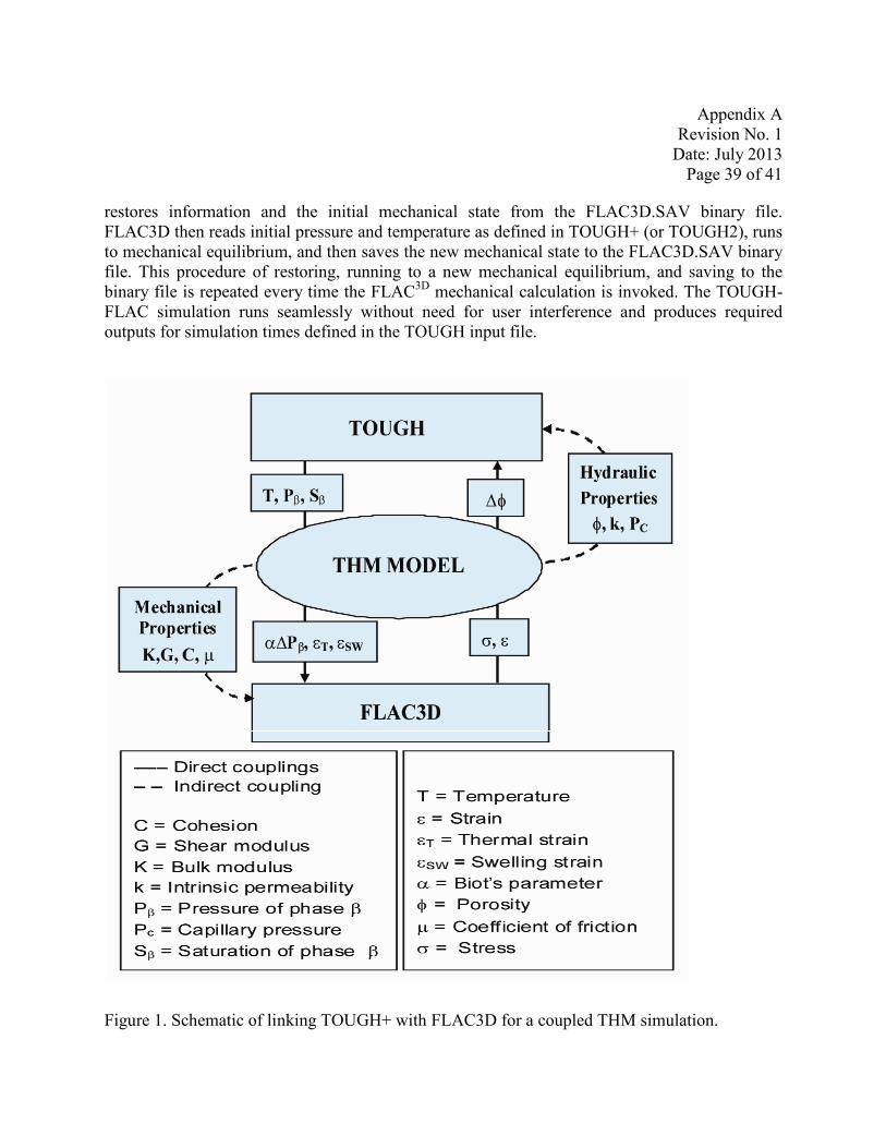
Appendix A Revision No. 1
Date: July 2013 Page 39 of 41
restores information and the initial mechanical state from the FLAC3D.SAV binary file. FLAC3D then reads initial pressure and temperature as defined in TOUGH+ (or TOUGH2), runs to mechanical equilibrium, and then saves the new mechanical state to the FLAC3D.SAV binary file. This procedure of restoring, running to a new mechanical equilibrium, and saving to the binary file is repeated every time the FLAC3D mechanical calculation is invoked. The TOUGHFLAC simulation runs seamlessly without need for user interference and produces required outputs for simulation times defined in the TOUGH input file.
Figure 1. Schematic of linking TOUGH+ with FLAC3D for a coupled THM simulation.

Appendix A Revision No. 1
Date: July 2013 Page 40 of 41
Figure 2. Steps for developing a coupled TOUGH-FLAC simulation of a particular problem.
References cited in Appendix A.
Kim, J., 2010. Sequential methods for coupled geomechanics and multiphase flow. Ph.D. Thesis, Department of Energy Resources Engineering, Stanford University, California, 264 pp.
Leverett, M.C., 1941. Capillary behavior in porous media. Trans, AIME, 142, 341–358.
Rutqvist, J., Freifeld, B., Min, K.-B., Elsworth, D., Tsang, Y., 2008a. Analysis of thermally induced changes in fractured rock permeability during eight years of heating and cooling at the Yucca Mountain Drift Scale Test. International Journal of Rock Mechanics and Mining Sciences 45, 1373–1389.
Rutqvist, J., Ijiri, Y., Yamamoto, H., 2010a. Implementing the Barcelona Basic Model into TOUGH-FLAC for analysis of geomechanical behavior of unsaturated soils. (Submitted).
Rutqvist, J., Moridis, G.J., 2009. Numerical Studies on the Geomechanical Stability of Hydrate-Bearing Sediments. Society of Petroleum Engineers (SPE) Journal 14, 267–282, SPE-126129.
Rutqvist, J., Moridis, G., 2008. Development of a Numerical Simulator for Analyzing the Geomechanical Performance of Hydrate-Bearing Sediments. In: Proceedings of the 42nd U.S. Rock Mechanics Symposium, San Francisco, California, USA, June 29-July 2, 2008, American Rock Mechanics Association, ARMA, Paper No. 139.
Rutqvist, J., Tsang, C.-F., 2003b. Analysis of thermal-hydrologic-mechanical behavior near an emplacement drift at Yucca Mountain. Journal of Contaminant Hydrology 62–63, 637–652.
Appendix A Revision No. 1
Date: July 2013 Page 41 of 41
Rutqvist, J., Tsang, C.-F., 2002. A study of caprock hydromechanical changes associated with CO2 injection into a brine aquifer. Environmental Geology 42, 296–305.
Rutqvist, J., Wu, Y.-S., Tsang, C.-F., Bodvarsson, G., 2002. A modeling approach for analysis of coupled multiphase fluid flow, heat transfer, and deformation in fractured porous rock. International Journal of Rock Mechanics and Mining Sciences 39, 429-442.
Settari, A., Mourits, F.M., 1998. A Coupled reservoir and Geomechanical Simulation System. Society of Petroleum Engineers (SPE) Journal 27(9), 219-226, SPE paper 50939.