Embed Size (px)
Citation preview

7/27/2019 pumps and piping article.docx
http://slidepdf.com/reader/full/pumps-and-piping-articledocx 1/16
Cheat Sheets: The Affinity Laws
In an earlier article in this series on the “Cheat Sheets,” I stated, “At 1,800 RPM, the impeller diameter in
inches, multiplied by itself (or squared), is approximately the shutoff head of the pump in feet.”
(“Unwritten Pump Rules,” Mar. ’08, page 40). That article, and those words, sparked some comments. Among them:
• My pumps spin at 1,750 RPM, not 1,800 RPM.
• Why is 1,800 RPM important?
• What about 3,600 RPM motors?
• How does the pump behave with pulleys or a gearbox?
• How does variable speed affect the pump?
The Affinity Laws answer these and other similar questions. The Affinity Laws govern the performance of
your pumps. The laws will help you extrapolate and predict pump performance at different velocities.
They are also useful to modify your pumps for new and different required duties.
Because most pumps are directly coupled to a standard industrial electric motor, the pump speed is most
often the motor speed. And because centrifugal pumps work with centrifugal force, the velocity and
diameter of the impeller determine the head, or pressure, the pump can develop.
The formula for the speed of the electric motor is:
Speed =
2 x 60-Hz x 60-sec
Number of Poles
where: • “2” is for alternating current (AC electricity)
• “60” is for 60-Hertz electricity. This means the electricity moves (oscillates) at 60-waves per second.
(Some countries have electricity at 50-Hz.)
• “60” seconds per minute. This gives us revolutions per minute.
• The “Poles” are the positive and negative electromagnetic fields in the motor.
Standard electric motor speeds at 60-Hz electricity.
• 2-pole motor = 3,600 RPM
• 4-pole motor = 1,800 RPM
• 6-pole motor = 1,200 RPM
• 8-pole motor = 900 RPM
Standard electric motor speeds at 50-Hz electricity.
• 2-pole motor = 3,000 RPM
• 4-pole motor = 1,500 RPM
• 6-pole motor = 1,000 RPM
• 8-pole motor = 750 RPM

7/27/2019 pumps and piping article.docx
http://slidepdf.com/reader/full/pumps-and-piping-articledocx 2/16
The speed can be adjusted by multiples just by changing to a motor with a different number of poles.
You may have noticed that a standard four-pole electric motor doesn’t exactly spin at 1,800 RPM. The
motor speed is rated at 1,785, 1,750, or 1,730 RPM. This is called the “slip” factor. It is part of the
motor’s design and determines if the motor has good startup torque or good running torque.
A low slip four-pole motor (1,785 RPM) is better for pumping a liquid that flows like water (low viscosity).
A motor with a low slip has good running torque. A high slip four-pole motor (1,725 RPM) is better for
pumping a liquid that flows like honey (high viscosity). A high-slip electric motor has good start-up
torque.
The variable-speed electric motor or VFD (variable frequency drive) is gaining in popularity. The first
models appeared about 30 years ago. By varying the motor’s frequency, the pump speed is also variable.
Before the VFD, industry traditionally employed gearboxes or belts and pulleys to adjust the pump speed.
DC motors, steam turbines, internal combustion engines, and hydraulic motors were employed to vary
the pump velocity.
The change in speed brings about a corresponding change in the head, flow, and power requirements of
the pump according to the Affinity Laws. Let’s look at them.
Stated simply, the Affinity Laws say:
1. The flow (GPM) varies proportionally with the change in speed. This means that twice the speed is
twice the flow. One-third speed is one-third the flow.
2. The pump head (pressure) varies with the square of the change in the speed. Two times the speed is
four times (22) the head generated. Eighty percent speed is 64 percent (.802) the head generated.
3. The power requirement (horsepower or kilowatts) varies by the cube of the change in speed. Two
times the speed would burn eight times (2
3
) the power. One half the speed would require one-eighth(.503) the power to drive the pump.
Algebraically, we would write the equations as:
• New Flow = Old Flow x (new speed/old speed)
• New Head = Old Head x (new speed/old speed)2
• New Power = Old Power x (new speed/old speed)3
Engineers study these laws in school, but sometimes they fail to apply their education when they take a
position in industry. Just last week, a staff engineer at a chemical plant wrote to me to inform me that his
company had purchased the wrong pump for a boiler. The boiler needed a feedwater pump rated at 950
ft. @ 30 GPM. Through some error, they took delivery on a pump rated at 950 ft. @ 60 GPM.
The pump was delivering twice the required flow to the boiler. The engineer sought my opinion regarding
two options:
1. Install a bypass valve and divert the excess flow back into the DA tank.
2. Mate the new pump to a VFD and correct the flow by reducing the speed.
I responded that neither option seemed correct. Energy is getting expensive; why waste energy to

7/27/2019 pumps and piping article.docx
http://slidepdf.com/reader/full/pumps-and-piping-articledocx 3/16
recirculate half the excess flow back into the DA tank? We should look to reduce energy consumption,
not waste it.
And, yes, the VFD at half speed would reduce the flow to 30 GPM. But it would also reduce the head by
the square of the velocity reduction. Half speed would be 25 percent head (.502 = .25). The pump would
only generate about 237 ft. at half speed and will deadhead against the boiler.
I told the engineer he should exchange the incorrect pump for the correct pump. I mean, if you bought
the wrong socks, or battery, or picture frame, you’d exchange it for the correct one … Right?
If he can’t return the whole pump, another possible option is to exchange or modify the impeller.
Regarding impellers, the diameter and the velocity of the impeller determines the head a pump can
generate. In this case, the engineer in question would need to keep the same impeller diameter and
speed to generate the 950 ft. of head required by the boiler.
The height of the impeller blades and the velocity will determine the flow a pump can deliver. The pump
company might make a “skinnier” impeller (less height to the blades) with adapter wear bands that mateto the volute. This would deliver less flow and conserve some power. I told him to send me his pump
curve and system curve with the next e-mail to explore this option.
Another set of the Affinity Laws deal with changes to the diameter of the impeller. If the speed should
remain a constant, the Affinity Laws state:
1. The flow (GPM) varies proportionally with the change in impeller diameter. This means that 10 percent
impeller reduction is 10 percent flow reduction.
2. The pump head (pressure) varies with the square of the change in the impeller diameter. If you
reduce the impeller diameter by 20 percent (80 percent original diameter), the pump head is reduced to
about 65 percent (.802 = .64) the original head generated.
3. The power requirement (BHp or Kw) varies by the cube of the diameter change. A 20 percentreduction in the impeller diameter (80 percent original diameter) would reduce the power consumption to
about half (.803 = .512). This is significant.
Algebraically, we would write the equations as:
New Flow = Old Flow x (new imp. diam. / old imp. diam.)
New Head = Old Head x (new imp. diam. / old imp. diam.)2
New Power = Old Power x (new imp. diam. / old imp. diam.)3
Why are these laws important to your work with pumps? Production managers and equipment operators
like variable-speed motors for the first Affinity Law. If they need 20 percent more production, they
increase the motor speed by 20 percent, and they get the production increase.
However, the head generated varies by the square of the velocity or impeller diameter change. For
example, increasing the pump speed by 20 percent would increase the head (pressure) by close to 50
percent. This could burst the screens in a downstream filter or overload a mechanical seal. Have you
noticed an increase in mysterious seal failure since installing a VFD?
A pump’s performance is composed of both a flow element and a head (pressure) element. This is the

7/27/2019 pumps and piping article.docx
http://slidepdf.com/reader/full/pumps-and-piping-articledocx 4/16
reason VFDs seem to work well on fans and blowers, but not necessarily on all pumps. You see, a fan or
blower is only a flow application; if you needed air pressure, you’d use a compressor, not a fan.
Sometimes people ask me, “How does my pump performance curve change at different motor speeds?”
The profile of the curve and its elements (head, flow, power, NPSHr, efficiency) don’t change. What
changes are the units of flow and head on the horizontal and vertical arms of the graph. They change bythe Affinity Laws. (There may be a slight improvement in efficiency with more velocity. Also, the NPSHr
may not vary precisely with the Affinity Laws because other factors participate in deriving the NPSHr.)
When I’m lecturing on pumps, I always spend plenty of time on the Affinity Laws. Either you dominate
them, or they’ll dominate you. Learn to use them or they will mess with your pumps and reliability. Put
them in your CHEAT SHEETS.
Larry Bachus , founder of pump services firm Bachus Company Inc., is a regular contributor to Flow
Control magazine. He is a pump consultant, lecturer, and inventor based in Nashville, Tenn. Mr. Bachus is
a member of ASME and lectures in both English and Spanish. He can be reached at [email protected]
or 615 361-7295.
Cheat Sheets: Unwritten Pump Rules
I had the occasion to read the owner’s manual for my car the other day. As I read, I became intrigued bythe information it didn’t offer.
For instance, the manual showed a cartoon picture of the dashboard. An arrow pointed to the gasolinegauge. Another arrow pointed to the low-fuel warning light. Another cartoon picture showed the gasoline
nozzle door and filler cap. The words in manual read, “Turn-off the engine to add fuel. Use regular (89-octane) gasoline.”
It didn’t offer any rules on when to add gasoline. It didn’t say how many miles I could drive after seeingthe low-fuel light. It offered no information on using higher-octane gasoline, or gasoline with ethanol.
On another page, a cartoon picture showed the clutch pedal and the transmission gearshift. The
instructions said to depress the clutch pedal before changing gears. But there were no rules on how farto depress the clutch pedal. No rules explained at what speed I should shift from second gear to thirdgear, or when I might downshift. The car companies assume we already know these rules.
Likewise, it is assumed that we already know the rules omitted from the owner’s manual of a new pump.So, I thought it would be useful here to cover some of the Pump Guy’s unwritten rules for pump
operation.
You can drive your car around the block and perceive a problem with it. You can observe your kids, look them in the face, and perceive if they have a problem, or if everything is going well. Most people have
one or two cars, and one or two kids.

7/27/2019 pumps and piping article.docx
http://slidepdf.com/reader/full/pumps-and-piping-articledocx 5/16
At work, you might be responsible for thereliability of 50 or 300 centrifugal pumps.How can you stand next to one of thesepumps, observe it, and perceive if thepump is sick or healthy? (No one teachesthis at the university!) The following are a
few generally accepted rules to keep inmind.
Rule No. 1: At 1,800 RPM, the impeller
diameter in inches, multiplied by itself (orsquared), is approximately the shutoff head
of the pump in feet.
Why does the first rule begin with 1,800
RPM? In the states, most industrial pumpsare powered by an electric motor on 60-Hz
electricity. The most popular industrialelectric motor (88 percent) is a four-pole
motor, meaning the rated velocity is 1,800RPM. (The motor may have a slip factor, so the actual speed might be 1,780 or 1,750 RPM. This isindicated on the electric motor identification tag.)
What is the shutoff head? The shutoff head is the beginning of the pump curve. It represents maximumelevation (in feet or meters) at zero flow. The performance curve proceeds to and ends at a point calledmaximum flow at zero elevation.
How do you begin with inches of impeller diameter and end with approximate feet of liquid elevation? It’stoo complicated to explain in this short column, but that’s the way it is. (If you would like more in-depthdiscussion of this issue, I encourage you to attend my next Pump Guy Seminar. See the promo box at theend of this article for details.)
Why do you say, approximate? It’s just a
rule or guide. It isn’t a law. It is accurate
within about 5 percent. There are variables
that affect the result.
What if the pump/motor is not spinning at
1,800 RPM? We’ll cover this in a future
“Cheat Sheet” article.
Rule No. 2: The best efficiency head
(BEH) of the pump is approximately 85
percent of the shutoff head.
Rule No. 3: Operate the pump at, or close
to, the BEH.
The pump doesn’t want to run at shutoff
head. It wants to run at the BEH or the
You can see the shutoff head of the 10-inch impeller is 103 feet. The shutoff head of the nine-inch impeller is 81-ft. The shutoff head of the eight-inch impeller is 64
feet.
The BEH of the 10-inch impeller is 88 ft., about 85 percent of the shutoff head.
BEH of the nine-inch impeller is 70 ft., about 85 percent of the shutoff head. BEH
of the eight-inch impeller is 54 ft., about 85 percent of the shutoff head.
7/27/2019 pumps and piping article.docx
http://slidepdf.com/reader/full/pumps-and-piping-articledocx 6/16
best efficiency point (BEP) on the curve. On most pumps, the BEH is approximately 85 percent of the
shutoff head. In almost all cases, the BEH is somewhere between 80 percent and 90 percent of the
shutoff head. So, 85 percent is a good starting point to determine the pump’s head and flow.
Do these three rules apply to all pumps? They apply to about 88 percent of all centrifugal pumps in
general industrial service. They don’t apply to special or exotic design centrifugal pumps or positive-displacement pumps.
What can I do with this information? Let’s say you’re standing next to a centrifugal pump mated to a
four-pole (1,800 RPM) motor. The pump/motor is properly assembled and installed. The pump and motor
shafts are aligned. The pump shaft is straight. The 13-inch impeller is balanced. The foundation is
adequate. The bearings and seal are adequate and properly installed. The pump elevates cold water into
an open vessel.
The differential pressure across the pump, as recorded on the suction and discharge gauges, is 46 PSI.
The gauges are calibrated, accurate, and adequate. Is the pump sick or healthy?
From the first rule, this pump should have a shutoff head of
approximately 170 ft. (13² = 169). From the second rule, you would expect this pump to have a BEH of
approximately 144 ft. (169 x 85 percent = 144).
Because the given liquid is cold water, this pump wants to inject approximately 60 to 65 PSI into the
system (144 ÷ 2.31 = 62.3 PSI. See “Cheat Sheets: 2.31 or .433,” Feb. ’08, page 40). Therefore, 46 PSI
differential pressure is unacceptable, and this pump is sick.
What do you mean, this pump is sick? The seal and bearings are stressed. You can expect premature
failure. Your seal and bearing sales people may pitch a tent in your plant and propose a mutually
beneficial alliance. Yeah, right!
You can expect mysterious vibrations. The vibration technician’s report will say, “Undetermined
vibrations. Engineer out!”
This pump may go into cavitation and might repeatedly trip the breaker on the electric motor, or fry the
windings. This pump will be a constant headache with repetitive maintenance and failures. The reliability

7/27/2019 pumps and piping article.docx
http://slidepdf.com/reader/full/pumps-and-piping-articledocx 7/16
engineer might declare this pump a “bad actor.” Get off the stupid train!
How would you fix this pump? Start by increasing the resistance on the discharge piping. This would
increase the differential pressure across the pump.
If the problems are mysterious vibrations, with bearing and seal failure, why don’t you tear apart andrebuild the pump? Why do you begin by adjusting the resistance on the system piping? (This will be
covered more in-depth in a later Cheat Sheet.)
People, about 80 percent of what you perceive to be mysterious pump, bearing, and seal failure is not
mysterious at all. The pump is indicating the problem for hours, days, and weeks before the breakdown
occurs. Learn to interpret your curves and gauges.
Larry Bachus , founder of pump services firm Bachus Company Inc., is a regular contributor to Flow
Control magazine. He is a pump consultant, lecturer, and inventor based in Nashville, Tenn. Mr. Bachus is
a member of ASME and lectures in both English and Spanish. He can be reached at [email protected]
or 615 361-7295.
What Is the Flowrate of a Pump Operating at
60% Speed?
A centrifugal pump is designed to operate at a water flow of 100 liters per minute and pressure of 100
meters of water column at full speed. What is the approximate flowrate if the pump is operated at 60
percent speed?
A. 77 liters per minute
B. 60 liters per minute
C. 36 liters per minute
D. 22 liters per minute
E. None of the above
Commentary
The Affinity Laws for centrifugal pumps are given as:
•
Flow is proportional to the pump speed• Pressure is proportional to the square of the pump speed
• Brake horsepower (energy input) is proportional to the cube of the pump speed
Noting that the first Affinity Law states that the flow is proportional to pump speed, it would seem
logical that the flow would be 60 liters per minute at 60 percent speed. Therefore, Answer B would
appear to be the correct answer.

7/27/2019 pumps and piping article.docx
http://slidepdf.com/reader/full/pumps-and-piping-articledocx 8/16
Not so fast. The pump operates at 60 percent speed, so it will generate a pressure of approximately 36
meters of water column. If the application involves pumping water into a process vessel located 40
meters above the pump, the flowrate will be zero – not 60 liters per minute. In this application, no flow
will occur until the pressure of the pump exceeds 40 meters of water column, which is at approximately
63 percent speed. In short, there is not enough information about the process and installation in the
problem statement to determine the flow at 60 percent of full speed, so the correct answer is Answer E.
Additional Complicating Factors
Presuming that additional process and installation information is given, this problem would be further
complicated if the vessel is operated under pressure. This is because different vessel pressures will
require different pump pressures and, hence, different pump speeds.
Flowmeter Piping Requirements
How Much Straight Run Is Enough?
When a fluid flowing through a pipe assumes a desirable flow profile, it moves uniformly with thegreatest velocities near the center of the pipe. Improper flowmeter installation can disturb this profile anddegrade measurement accuracy. Flow-profile distortion and swirl — the two most prominent types of fluid disturbance that affect a meter’s flow coefficients — are typically the product of improper pipingconfiguration.
Fluid profile distortion occurs when an obstruction — such as a partially open valve or a poorly mountedflange gasket — partially blocks the pipe. Swirl occurs when the fluid moves through piping bends indifferent planes. Swirl is far more difficult to correct than flow-profile distortion. Obstructions upstream
and near the flowmeter can cause errors ranging beyond 50 percent.
Flowmeter manufacturers will recommend various lengths of straight pipe upstream and downstream of the flowmeter to attain a fully developed desirable flow profile. Long straight-pipe lengths can be avoidedthrough the use of flow-straightening devices and flow conditioners. Flow-straightening devices include
tube bundles, perforated plates, and internal tabs. These solutions reduce swirl, but not flow profilevariations; some may even introduce a distorted profile. Flow conditioners can reduce swirl and also
mimic a fully developed profile. A grated plate, for example, can introduce such a profile.
Differential-Pressure FlowmetersDP flowmeters measure the drop in pressure across a flow element in the piping, such as an orifice plate.The measured flowrate is a function of the pressure drop. So the flowmeter consists of the flow element
in the piping, as well as a nearby differential-pressure meter. Small tubes, called impulse lines, on either
side of the flow element lead to the DP meter for measurement.
Professional organizations, such as ISA (www.isa.org ), ANSI (www.ansi.org ), API (www.api.org ), ASME(www.asme.org ), and AGA (www.aga.org ), offer installation guidelines for DP flowmeter installations.These guidelines help to minimize disturbances to the fluid-velocity profile. Often, for example,measurements of temperature and static pressure are desirable in addition to flowrate. To minimize flowdisturbances from an added pressure sensor, install a tee for connection to the appropriate DP impulseline. Similarly, install a thermowell used for temperature measurement at least 10 pipe diametersdownstream of the flow element. Such installations should be characterized by smoothly ground welds
7/27/2019 pumps and piping article.docx
http://slidepdf.com/reader/full/pumps-and-piping-articledocx 9/16
and trimmed gaskets to eliminate protrusions into the fluid stream.
Straight-pipe runs upstream and downstream from the DP flow element help to guarantee a fullydeveloped fluid-velocity profile that permits a predictable pressure drop. For an orifice, the length of straight run required depends on both the beta ratio of the installation and on the nature of the upstreamcomponents in the pipeline. (Beta ratio is the diameter of the orifice divided by the pipe diameter.) For
example, when a single 90-degree elbow precedes an orifice plate, the straight-pipe requirement rangesfrom six to 20 pipe diameters as the beta ratio increases from 0.2 to 0.8.
The size and orientation of the impulse-line pressure taps depend on both the pipe size and the process
fluid. The recommended maximum diameters of pressure-tap holes through the pipe or flange are:• ¼” inch for pipes under two inches in diameter;• 3⁄8” inch for two- and three-inch diameter pipes;• ½” for four- to eight-inch diameter pipes; and• ¾” inch for pipes larger than eight inches in diameter.
Size both pressure taps and leads with the same diameter. Where the hole breaks through the inside pipe
surface, make sure it is flush with the inside pipe surface with no roughness, burrs, or wire edges.Connections to pressure taps should be made by nipples, couplings, or adaptors welded to the outside
surface of the pipe.
On services where the process fluid can plug the pressure taps or might gel or freeze in the impulse lines,consider chemical seals. Connection sizes are usually larger in these cases. When using chemical seals,assure that the two connecting capillaries that route to the DP meter experience the same temperatureand keep them both shielded from sunlight.
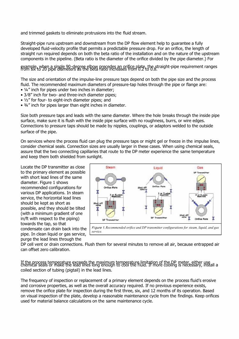
Locate the DP transmitter as closeto the primary element as possiblewith short lead lines of the samediameter. Figure 1 showsrecommended configurations forvarious DP applications. In steamservice, the horizontal lead linesshould be kept as short aspossible, and they should be tilted(with a minimum gradient of onein/ft with respect to the piping)towards the tap, so thatcondensate can drain back into the
pipe. In clean liquid or gas service,purge the lead lines through theDP cell vent or drain connections. Flush them for several minutes to remove all air, because entrapped air
can offset zero calibration.
If the process temperature exceeds the maximum temperature limitation of the DP meter, either usechemical seals or make the lead lines long enough to cool the fluid. If more cooling is necessary, install acoiled section of tubing (pigtail) in the lead lines.
The frequency of inspection or replacement of a primary element depends on the process fluid’s erosiveand corrosive properties, as well as the overall accuracy required. If no previous experience exists,remove the orifice plate for inspection during the first three, six, and 12 months of its operation. Basedon visual inspection of the plate, develop a reasonable maintenance cycle from the findings. Keep orificesused for material balance calculations on the same maintenance cycle.
Fi gure 1. Recommended orifice and DP transmitter configurations for steam, liquid, and gas
service.

7/27/2019 pumps and piping article.docx
http://slidepdf.com/reader/full/pumps-and-piping-articledocx 10/16
Electromagnetic Flowmeters Always pipe an electromagnetic flowmeter (magmeter) so it is full of liquid. The pipe configuration shouldavoid a buildup or accumulation of any secondary phase (solids or air). Any entrained air should becarried out of the meter by flow, or by buoyancy (at zero flow). Likewise, any solids should fall from themeter by gravity under zero flow. You can install magmeters in horizontal lines, but best practice calls for
installation in vertical lines with upwards flow (Figure 2).
Pipe the magmeter to remain full at zero flow. Otherwise the output can become erratic because of electrode exposure to air. If draining at zero flow is inevitable, use empty pipe detection options to
prevent erratic output.
Magmeters are relatively insensitive to errors caused bynonsymmetrical velocity patterns or swirl. The general ruleof thumb for straight piping is a five-diameter length of
piping upstream and three diameters downstream from themeter (measured from the center of the tube). Independent
testing has shown that magmeters may be affected bypiping effects when the length of upstream straight pipe is
less than three pipe diameters. Errors from piping effectsgenerally run between 0.1 percent and 1.5 percent,depending on the exact configuration of piping and length of pipe run upstream of the meter.
The magnetic field across the electrodes is very small,making the magmeter susceptible to stray ground currentsin the pipeline. If the pipeline is made of nonconductingmaterials, such as plastic, or is lined with an insulatingmaterial, these stray ground potentials can cause significantmeasuring errors. Five or six millivolts of stray potential in the measuring section of the flowmeter canrender the signal meaningless. The transmitter will confuse this stray potential with the actual signal andprovide inaccurate flow readings.
If the pipeline is made of an unlined conducting material, the process ground should be excellent, and nofurther measures are normally required. As a precaution, install grounding straps between the pipeflanges and magmeter flanges, and connect one pipe flange to a good ground, as shown in Figure 3.
If the connecting pipe is not electrically conductingor is lined with insulating material, use grounding
rings, disks, or electrodes. Strap the groundingdisks or rings to the detector head flanges at eitherend. If the magmeter contains grounding
electrodes, the manufacturer will connect them toground inside the magmeter casing.
Insertion MagmetersInsertion magmeter probes offer an economical
alternative to full-bore meters or a verificationdevice to check the performance of an existing
meter. Correctly applied, these sensors providereliable, maintenance-free operation with goodaccuracy in many difficult applications andindustries. Insertion magmeters suit both temporary
Fi gure 2. When installing magmeters, avoid downward
flows. Horizontal configurations following an elbowrequire five pipe diameters of straight pipe upstream from
the meter.
Fi gure 3. Grounding recommendations for conductive and
nonconductive piping.

7/27/2019 pumps and piping article.docx
http://slidepdf.com/reader/full/pumps-and-piping-articledocx 11/16
and permanent applications in pipes up to 320-inches diameter. Hot-tap capabilities through a valve allowinstallation while the pipe is under full working conditions.
Preferably, the probe’s end will reach the centerline of the pipe following installation. But if the probe willexperience exceptionally high flow velocities at the pipe’s center, raise it to a point in the piperepresenting the flow’s mean velocity. This point is generally 1⁄8” of the pipe diameter. Manufacturers
provide tables indicating the maximum flow velocity for various insertion lengths.
For optimum operation, the pipe conditions upstream from the insertion magmeter must be good. ISO7145, for example, calls for 25 to 50 diameters of straight pipe upstream from the insertion meter. If
these lengths are not possible, instrument engineers must determine the flow profile to provide goodinsertion magmeter accuracies.
Vortex Flowmeters Sizing a vortex meter by the piping line size is poor practice. The line-size vortex meter may not work at
all. If the range of flowrates is unknown, first make some approximate measurements (using portablepitot or clamp-on ultrasonic devices). About half of all vortex meter installations require the “neckingdown” of oversized process piping by concentric reducers and expanders (Figure 4). Even with flowstraightening devices installed, the installation will require some straight (relaxation) piping.
The vortex meter requires a well-developed andsymmetrical flow velocity profile, free from anydistortions or swirls. This necessitates the use of relatively long straight piping upstream anddownstream from the meter to condition the flow.Swirl meters, which are similar to vortex meters,contain flow-straightening elements, thus requiringless straight pipe.
The straight length of pipe for the vortex metermust be the same size as the meter and its lengthshould be about the same as required for an orificeinstallation with a beta ratio of 0.7. Most vortexflowmeter manufacturers recommend a minimumlength of 30 pipe diameters downstream of controlvalves, and three-to-four pipe diameters betweenthe meter and downstream pressure taps.Temperature elements should be small and locatedfive-to-six pipe-diameter lengths downstream.
Vortex meters can be installed vertically, horizontally, or at any angle, as long as the pipe is kept full.Installing the meter in a vertical line with upward flow will always keep the pipe full. When the flow is
horizontal or downward in a vertical line, keep the downstream piping elevated to trap the fluid. Usecheck valves to keep the piping full of liquid in the no-flow condition. If the replacement of the meter in a
particular piping configuration requires stopping the flow, block and bypass valves can be installedaround the meter.
Mating flanges (on Schedule 40 or Schedule 80 mating piping) must have the same diameter and smoothbore as the vortex flowmeter. Use weld-neck flanges rather than reducing flanges. Make sure the inner
surface of the mating pipe is free from mill scale, pits, holes, reaming scores, and bumps for a distance of four pipe diameters upstream and two pipe diameters downstream of the meter. The bores of the meter,gaskets, and adjacent piping must be carefully aligned to eliminate any obstructions or steps.
Fi gure 4. Vortex meters must often be smaller than line size.
Installations should keep the meter full of liquid at zero flow.

7/27/2019 pumps and piping article.docx
http://slidepdf.com/reader/full/pumps-and-piping-articledocx 12/16
You can avoid excessive pipe vibration by supporting the piping on both sides of the meter, or by rotatingthe meter so that the sensor is moved out of the plane of the vibration. Process noise due to valvechattering, steam traps, or pumps can result in high readings or nonzero readings under no-flowconditions. Most meter electronics allow for increasing the noise filter settings, but increased noisereduction usually also decreases the low-flow sensitivity of the meter. One option is to relocate the meterto a less noisy part of the process.
Direct Mass-Flow Measurement Coriolis flowmeters measure mass flow directly and offer few installation limitations. These flowmetersare insensitive to velocity profile distortion and swirl. This characteristic avoids the necessity of straight
runs of relaxation piping upstream and downstream of the meter to condition the flow. Additionally,Coriolis flowmeters handle all fluids regardless of their Reynolds number.
Install Coriolis flowmeters so they remain full of liquid and so air cannot get trapped inside the tubes. Insanitary installations, make sure the meter drains completely. The most desirable installation is in vertical
pipes with upward flow, but installation in horizontal piping is also acceptable. Installations where thefluid flows downward in a vertical pipe are not recommended. Good practice calls for upstream
installation of strainers, filters, or air/vapor eliminators as necessary to remove all undesirable secondaryphases and air bubbles. Install control valves downstream from Coriolis meters to increase backpressure
on them and to decrease the probability of cavitation or flashing.
Deposits and strong vibration can degrade accuracy. Newer Coriolis flowmeter designs, however, resistnormal pipe vibration if the surrounding process piping properly supports the meter. No special supportsor pads are needed for the flow tube. If the installation instructions require special hardware or supports,the meter design is likely to be sensitive to vibration.
Turbine FlowmetersTypical manufacturer specifications for turbine meters call for straight-pipe lengths of 10-15 pipediameters upstream and five diameters downstream. Additional straight-pipe recommendations include:• 20 pipe diameters for 90-degree elbow, tee, filter, strainer, or thermowell;
• 25 pipe diameters for a partially open valve; and• 50 pipe diameters for two elbows in different planes or if the flow is spiraling.
Typically, turbine meters require the installation of
straightening vanes and flushing strainers or filters
upstream of the meter. Straightening vanes can
reduce the lengths of straight pipe otherwise
required. Strainers and filters eliminate solids
entrained in the fluid that can otherwise damage
the turbine rotor.
Because valves installed in the piping can cause
significant errors, use full-bore shutoff valves that
are fully open during meter operation. Install
control valves only on the downstream side of the
meter.
A sudden pressure drop upstream can result in
flashing or cavitations within the turbine meter. Flashing causes the meter to read high, while cavitations
result in rotor damage.
Fi gure 5. Straight-pipe diameter recommendations for vortex and
swirl meters for various configurations.

7/27/2019 pumps and piping article.docx
http://slidepdf.com/reader/full/pumps-and-piping-articledocx 13/16
Downstream pressure must equal 1.25 times the vapor pressure plus twice the pressure drop. Small
amounts of air entrainment (<100 mg/l) will also make the meter read high, while large quantities of air
can destroy the rotor. For a sudden drop in flowrate, the turbine meter may read high because of the
stored inertia in the rotor.
Ultrasonic Flowmeters Ultrasonic flowmeters come in two basic types — Doppler and transit time. Doppler flowmeters measure
a frequency shift from beam reflections off bubbles or particles in a fluid. Transit-time flowmeters
measure the time difference between ultrasonic beams moving with and against the flow. Clean fluid
applications will generally rule out Doppler flowmeters. Transit-time meters work well with clean and
viscous liquids.
Flowmeters having multiple ultrasonic beams are less affected by flow profile disturbances than single-
beam meters. Excess solids or fluids with entrained gases may block the ultrasonic pulses in transit-time
meters. Raw wastewater applications, for example, usually have too few acoustic discontinuities for
Doppler and are not clean enough for transit-time measurements.
Most recommendations call for fluid Reynolds numbers less than 4,000 (laminar flow) or above 10,000
(turbulent flow). Nonlinearities in the transition region between these two Reynolds numbers degrade
meter accuracies.
Ultrasonic flowmeters are not applicable to slurries that are acoustically absorbent, such as lime or kaolin
slurries. Highly absorbent solids attenuate the signal below usable strength.
The ultrasonic flowmeters should be installed upstream of flow obstacles, such as elbows, reducers, or
valves. Ensure that the longest possible straight pipe is between the obstacle and the meter. The length
of straight pipe can be reduced to five pipe diameters if an additional error of 1 percent maximum is
acceptable.
Paying attention to these recommendations for flowmeter installations will help ensure successful
applications with good accuracies.
Q&A: Piping Material Selection
Q: Respectively, what are the key application advantages/disadvantages of nonmetallic, metallic, and
nonmetallic-lined
metallic pipe?
A: It’s important to note that all piping materials have inherent strengths and weaknesses. As such, no
one material is ideal for all applications.
Metal has been used longer than any other material in piping applications. On the positive side, metal
offers higher pressure bearing capabilities than alternative materials. In addition, it is not temperature
sensitive, which is to say that its pressure bearing capabilities are not reduced by increases in

7/27/2019 pumps and piping article.docx
http://slidepdf.com/reader/full/pumps-and-piping-articledocx 14/16
temperature. And with metal, hangers can be spaced farther apart to save on installation costs and labor.
The most serious disadvantage of metal is interior and exterior corrosion. Aggressive fluids inside the
pipe may cause it to corrode from within, while elements such as salt in the air can cause external
corrosion. Metal is also subject to scale buildup, which restricts flow.
In addition, it is more expensive to install, both from a material cost and labor perspective. A cost
analysis prepared by the Plastics Pipe and Fittings Association (www.ppfahome.org ) in 2003 estimated
100 feet of six-inch carbon steel pipe cost $22,789 vs. $18,932 for the same length of CPVC pipe.
Nonmetallic offers lower material costs than metal, and its labor costs are also significantly lower due to a
fast, easy solvent cement joining system. From a long-term performance perspective, CPVC is 100
percent immune to both interior and exterior corrosion in most recommended applications. It offers
strong insulating advantages, which increase energy efficiency, minimize condensation, and make it safe
to touch, regardless of the temperature of the liquid being transported. It is also lighter in weight, which
makes it easier to maneuver on the job site.
On the negative side, CPVC has lower pressure bearing capabilities, which are dependent on fluid
temperature. During installation, CPVC pipe also requires more hangers to support the pipe. This can be a
problem in areas where there is insufficient space for additional hangers.
Nonmetallic-lined metallic pipe combines the advantages of metal and CPVC, while minimizing many of
the disadvantages of both pipe materials. It is immune to internal corrosion (although still subject to
external corrosion); scale buildup concerns are eliminated; and the pipe has the same superior pressure
bearing capabilities as metal.
A major disadvantage is cost. Nonmetallic-lined pipe is by far the most expensive piping material of the
three being evaluated in this article. In addition, it requires a difficult, labor-intensive joining process.Finally, if a break in the lining occurs, it can become a major source for future pipe failure.
Q: What are the most important elements of an effective piping design strategy?
A: Most critical to a successful piping systems design strategy is to choose a material that best suits the
application. Many design elements should be considered before making a final choice, including: the type
of fluid being handled; the various temperatures and pressures at which the system will be operating; the
desired service life of the system; economics (short-term and long-term); product availability of the pipe,
valve and fitting sizes; external factors such as exposure to UV light, corrosive soil, or atmospheric
conditions, etc.; and the ease of system maintenance.
Q: What are some of the key standards for piping systems design? How important are these standards
in an overal systems design strategy?
A: Although there are ASTM standards that provide general installation guidance, it’s more important for
designers to review the specific manufacturer’s installation guidelines. This is especially true when using a

7/27/2019 pumps and piping article.docx
http://slidepdf.com/reader/full/pumps-and-piping-articledocx 15/16
nonmetallic material. Metal has been used for many years, so most designers are already familiar with
potential challenges. But the newer, more specialized materials, like CPVC, have different instructions and
guidelines. If it’s your first time using a nonmetallic material, you need to become thoroughly familiar
with its unique attributes and uses.
Keep in mind, too, that not all CPVC is the same. Manufacturers use different base resins, which canaffect material performance significantly. Some companies also offer more technical support and chemical
resistance data to help designers through unusual situations or challenges. This level of support and
information should be taken into consideration when choosing a material manufacturer.
Q: What one piece of advice would you offer to piping systems designers?
A: More than anything, it’s important to keep an open mind and consider all the options before making a
decision about piping material. Don’t be afraid to investigate new materials. Evaluate all alternatives for
their individual strengths and weaknesses. Do your homework to determine what’s best for a particular
application. There are a number of resources to help familiarize users with the newer, nonmetallicoptions. Two resources to consider are the Plastic, Pipe and Fittings Association (PPFA,
www.ppfahome.org ) and the Plastic Pipe Institute (PPI, www.plasticpipe.org ).
Pipe Schedule & Flow Velocity
What's the Impact on Flow Measurement?Sometimes we understand the effect of a certain error, but we do not take the time to determine
its magnitude. Such can be the case of making an error with regard to pipe schedule. Assume a
six-inch ultrasonic flowmeter in liquid service is designed and calibrated for Schedule 40 pipe,
but is instead installed on a Schedule 80 pipe. How much does the flow measurement change dueto the measurement of a different velocity in the metering section?
A. Increases by approx. 10% B. Increases by approx. 5% C. No effect D. Decreases by approx. 5% E. Decreases by approx. 10%
Commentary The inside diameter of six-inch Schedule 40 and Schedule 80 pipes are 6.065 and 5.761 inches
respectively. Because the inside diameter of the Schedule 80 pipe is smaller, the same amount of liquid will travel at a higher velocity in the Schedule 80 pipe metering section than in the
Schedule 40 pipe. Therefore, when the flowmeter measures the fluid velocity in the metering
section, the flowmeter measurement in the Schedule 80 metering section will be higher. This
effectively eliminates Answer C, Answer D, and Answer E. The issue then becomes quantifyinghow much higher the flowmeter will measure.
Applying the equation of continuity, it can be seen that the ratio of the velocity in the Schedule
7/27/2019 pumps and piping article.docx
http://slidepdf.com/reader/full/pumps-and-piping-articledocx 16/16
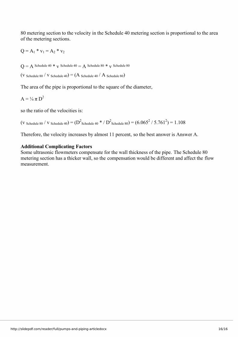
80 metering section to the velocity in the Schedule 40 metering section is proportional to the area
of the metering sections.
Q = A1 * v1 = A2 * v2
Q = A Schedule 40 * v Schedule 40 = A Schedule 80 * v Schedule 80
(v Schedule 80 / v Schedule 40) = (A Schedule 40 / A Schedule 80)
The area of the pipe is proportional to the square of the diameter,
A = ¼ π D2
so the ratio of the velocities is:
(v Schedule 80 / v Schedule 40) = (D2
Schedule 40 * / D2
Schedule 80) = (6.0652
/ 5.7612) = 1.108
Therefore, the velocity increases by almost 11 percent, so the best answer is Answer A.
Additional Complicating Factors Some ultrasonic flowmeters compensate for the wall thickness of the pipe. The Schedule 80
metering section has a thicker wall, so the compensation would be different and affect the flowmeasurement.