Embed Size (px)
Citation preview
Copyright © Carrier Corp. 2005
Technical Development Program
DISTRIBUTION SYSTEMS
Water Piping and Pumps
PRESENTED BY:
Michael Ho
424-262-2144
Copyright © Carrier Corp. 2005
Section 1 Introduction
Section 2 Types of Piping Systems
Section 3 Water Distribution Systems
Section 6 Typical Piping Details at Equipment
Section 4 Direct and Reverse Return Systems
Section 7 System Piping Arrangements
Section 8 Pump Basics and Types of Pumps
Section 10 Summary
Section 5 Water Piping Components and Accessories
Section 9 Pipe Sizing and Pump Selection Example
Menu
Copyright © Carrier Corp. 2005
SECTION 1
Introduction
WATER PIPING AND PUMPS
Copyright © Carrier Corp. 2005
Objectives
• Compare the 3 types of piping systems
• Identify the 4 types of water distribution systems
• Differentiate between direct return and reverse return systems
• Identify the various valves and hydronic accessories available for use in piping systems
• Diagram typical piping hookups for chillers, pumps, and cooling towers
• Size the piping for a closed loop and an open recirculating loop system
• Identify the types of water pumps, their features, and the selection process
Section 1 – Introduction
Copyright © Carrier Corp. 2005
SECTION 2
Types of Piping Systems
WATER PIPING AND PUMPS
Copyright © Carrier Corp. 2005
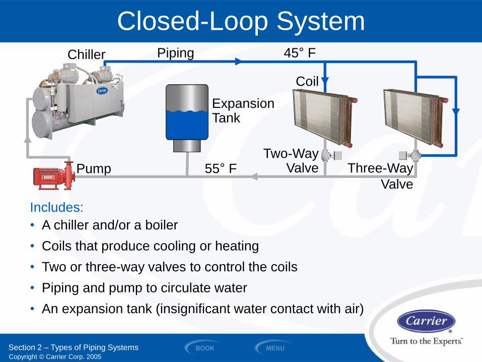
Closed-Loop System
Coil
Expansion Tank
Chiller
Two-Way Valve Pump
Includes:
• A chiller and/or a boiler
• Coils that produce cooling or heating
• Two or three-way valves to control the coils
• Piping and pump to circulate water
• An expansion tank (insignificant water contact with air)
Section 2 – Types of Piping Systems
Three-Way
Valve
Piping 45° F
55° F
Copyright © Carrier Corp. 2005
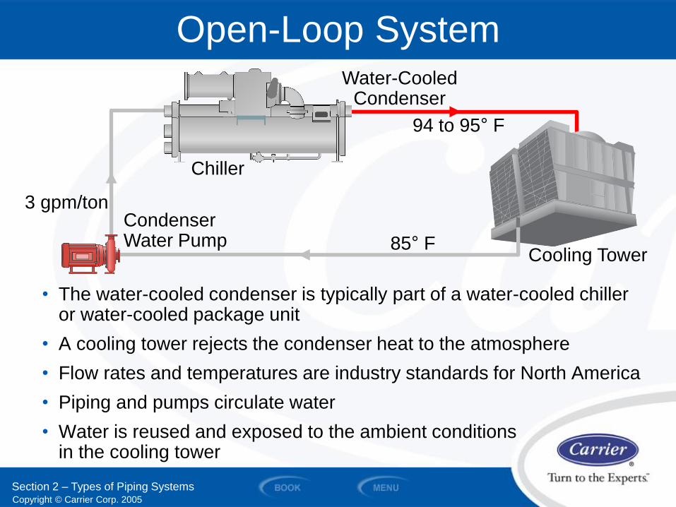
Open-Loop System
• The water-cooled condenser is typically part of a water-cooled chiller or water-cooled package unit
• A cooling tower rejects the condenser heat to the atmosphere
• Flow rates and temperatures are industry standards for North America
• Piping and pumps circulate water
• Water is reused and exposed to the ambient conditions in the cooling tower
Water-Cooled Condenser
94 to 95° F
Chiller
Cooling Tower 85° F
Condenser Water Pump
3 gpm/ton
Section 2 – Types of Piping Systems
Copyright © Carrier Corp. 2005
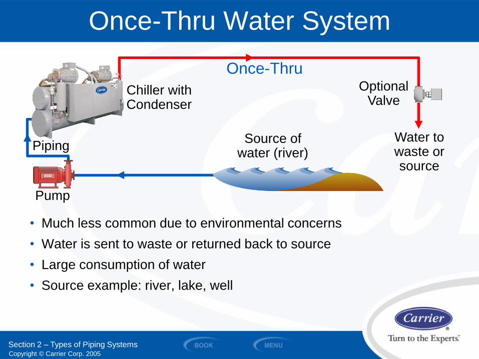
Once-Thru Water System
• Much less common due to environmental concerns
• Water is sent to waste or returned back to source
• Large consumption of water
• Source example: river, lake, well
Water to waste or source
Piping
Pump
Source of water (river)
Chiller with Condenser
Once-Thru Optional
Valve
Section 2 – Types of Piping Systems
Copyright © Carrier Corp. 2005
SECTION 3
Water Distribution Systems
WATER PIPING AND PUMPS
Copyright © Carrier Corp. 2005
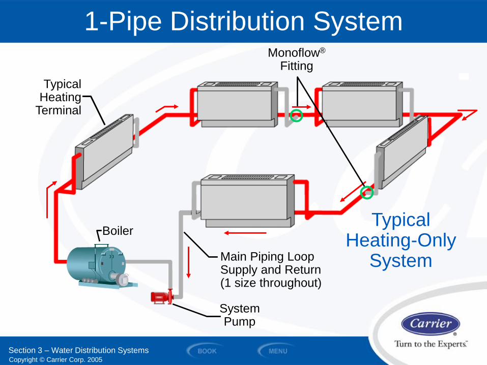
Typical Heating
Terminal
1-Pipe Distribution System
Main Piping Loop Supply and Return (1 size throughout)
Monoflow®
Fitting
Typical Heating-Only
System
Boiler
System Pump
Section 3 – Water Distribution Systems
Copyright © Carrier Corp. 2005
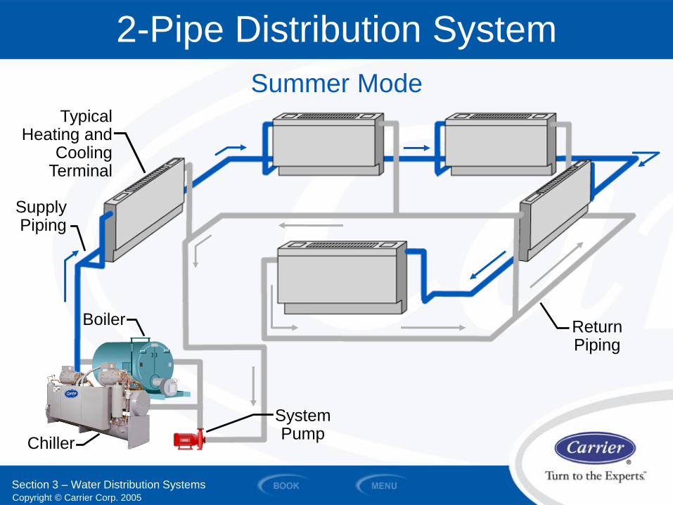
Supply Piping
2-Pipe Distribution System
Return Piping
Boiler
Summer Mode
System Pump
Chiller
Section 3 – Water Distribution Systems
Typical Heating and
Cooling Terminal
Copyright © Carrier Corp. 2005
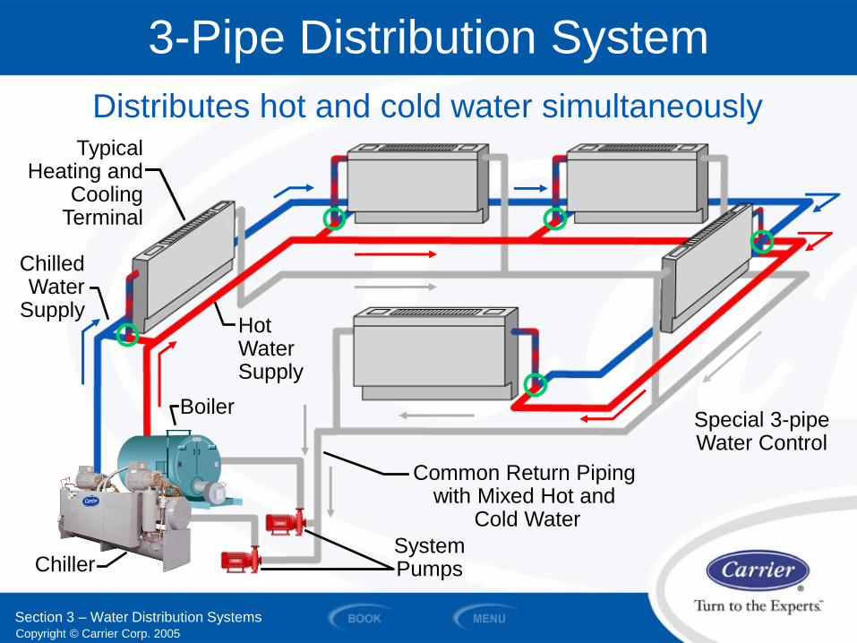
3-Pipe Distribution System
Section 3 – Water Distribution Systems
Special 3-pipe Water Control
Chilled Water
Supply
Common Return Piping with Mixed Hot and
Cold Water
Chiller
Boiler
Hot Water Supply
System Pumps
Distributes hot and cold water simultaneously Typical
Heating and Cooling Terminal
Copyright © Carrier Corp. 2005
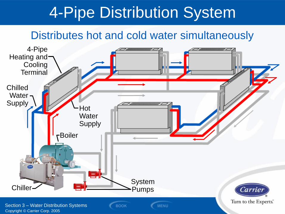
4-Pipe Distribution System
Chiller System Pumps
Distributes hot and cold water simultaneously
Hot Water Supply
Boiler
Section 3 – Water Distribution Systems
Chilled Water
Supply
4-Pipe Heating and
Cooling Terminal

Copyright © Carrier Corp. 2005
SECTION 4
Direct and Reverse Return Systems
WATER PIPING AND PUMPS
Copyright © Carrier Corp. 2005
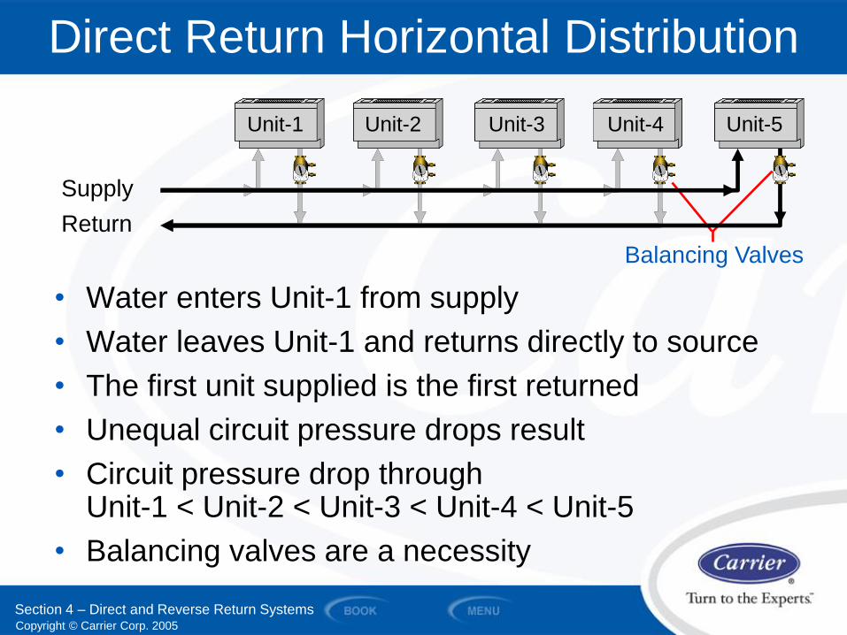
• Water enters Unit-1 from supply
• Water leaves Unit-1 and returns directly to source
• The first unit supplied is the first returned
• Unequal circuit pressure drops result
• Circuit pressure drop through Unit-1 < Unit-2 < Unit-3 < Unit-4 < Unit-5
• Balancing valves are a necessity
Balancing Valves
Return
Direct Return Horizontal Distribution
Supply
Unit-5 Unit-1 Unit-2 Unit-3 Unit-4
Section 4 – Direct and Reverse Return Systems
Copyright © Carrier Corp. 2005
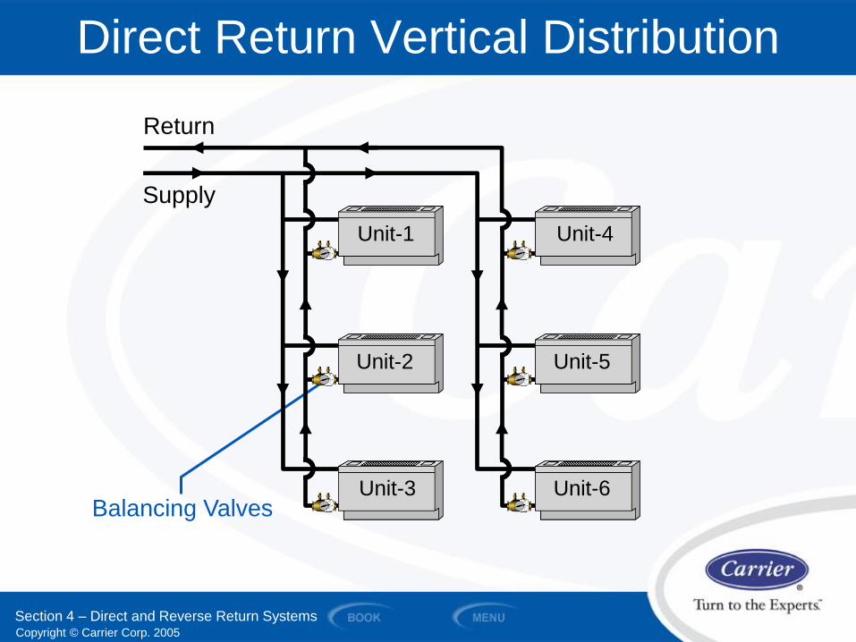
Direct Return Vertical Distribution
Section 4 – Direct and Reverse Return Systems
Return
Supply
Balancing Valves
Unit-5
Unit-1
Unit-2
Unit-3
Unit-4
Unit-6
Copyright © Carrier Corp. 2005
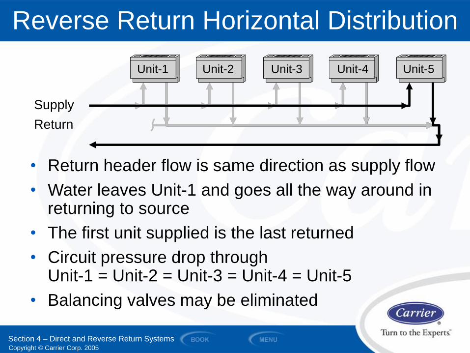
Return
Reverse Return Horizontal Distribution
Supply
• Return header flow is same direction as supply flow
• Water leaves Unit-1 and goes all the way around in returning to source
• The first unit supplied is the last returned
• Circuit pressure drop through Unit-1 = Unit-2 = Unit-3 = Unit-4 = Unit-5
• Balancing valves may be eliminated
Unit-5 Unit-1 Unit-2 Unit-3 Unit-4
Section 4 – Direct and Reverse Return Systems
Copyright © Carrier Corp. 2005
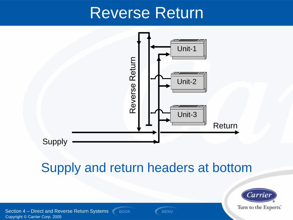
Reverse Return
Supply and return headers at bottom
Supply
Return
Unit-1
Unit-2
Unit-3
Section 4 – Direct and Reverse Return Systems
Copyright © Carrier Corp. 2005
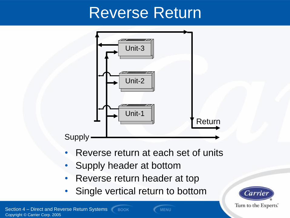
Reverse Return
• Reverse return at each set of units
• Supply header at bottom
• Reverse return header at top
• Single vertical return to bottom
Return
Supply
Unit-2
Unit-3
Unit-1
Section 4 – Direct and Reverse Return Systems
Copyright © Carrier Corp. 2005
SECTION 5
Water Piping Components
and Accessories
WATER PIPING AND PUMPS
Copyright © Carrier Corp. 2005
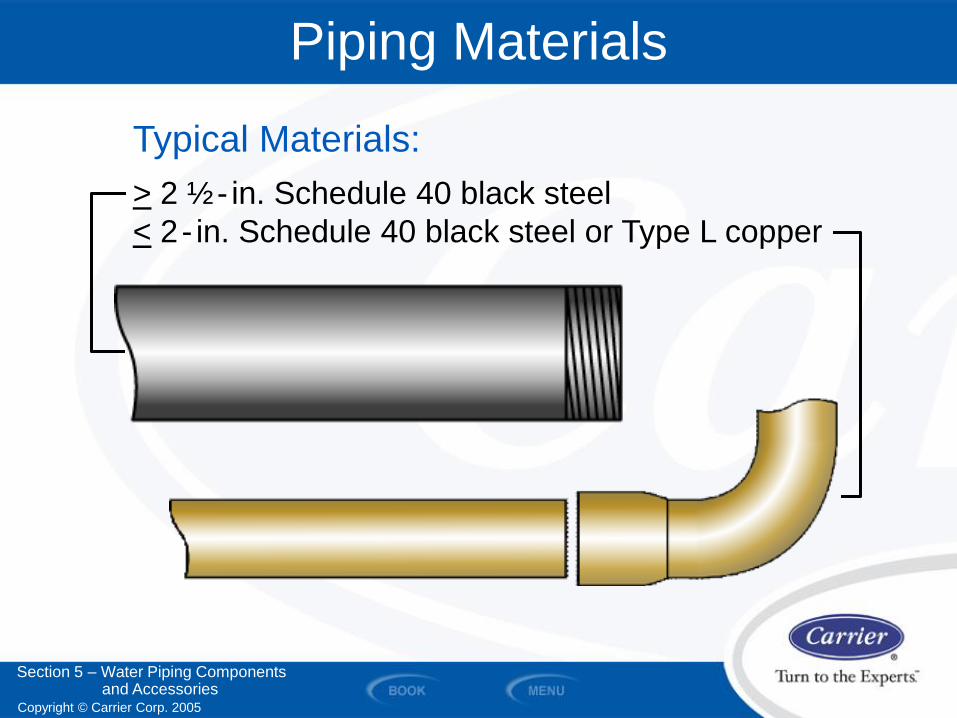
Piping Materials
Typical Materials:
> 2 ½ - in. Schedule 40 black steel
< 2 - in. Schedule 40 black steel or Type L copper
Section 5 – Water Piping Components and Accessories
Copyright © Carrier Corp. 2005
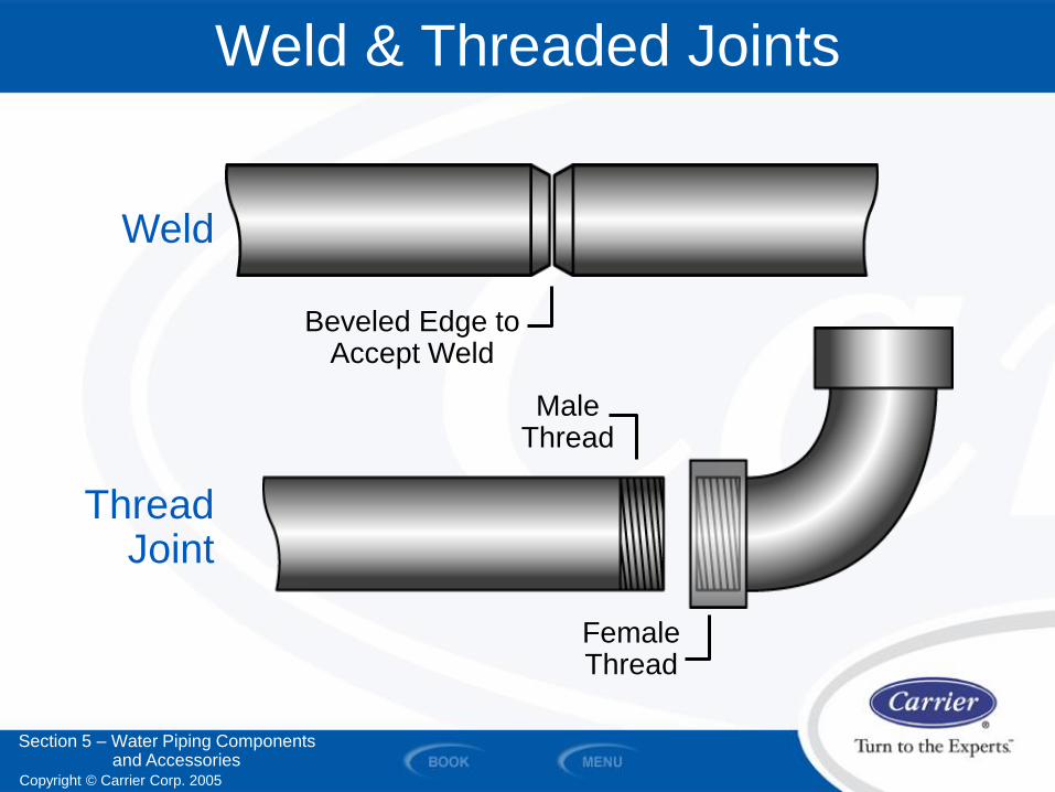
Weld & Threaded Joints
Female Thread
Male Thread
Beveled Edge to Accept Weld
Weld
Thread Joint
Section 5 – Water Piping Components and Accessories
Copyright © Carrier Corp. 2005
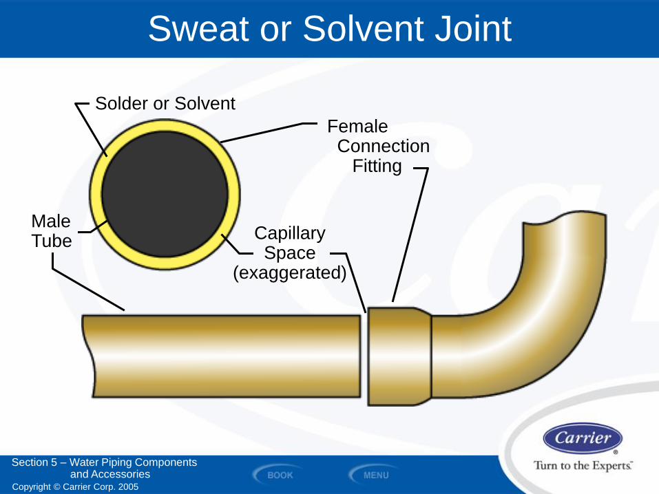
Sweat or Solvent Joint
Solder or Solvent
Male Tube Capillary
Space (exaggerated)
Female Connection Fitting
Section 5 – Water Piping Components and Accessories
Copyright © Carrier Corp. 2005
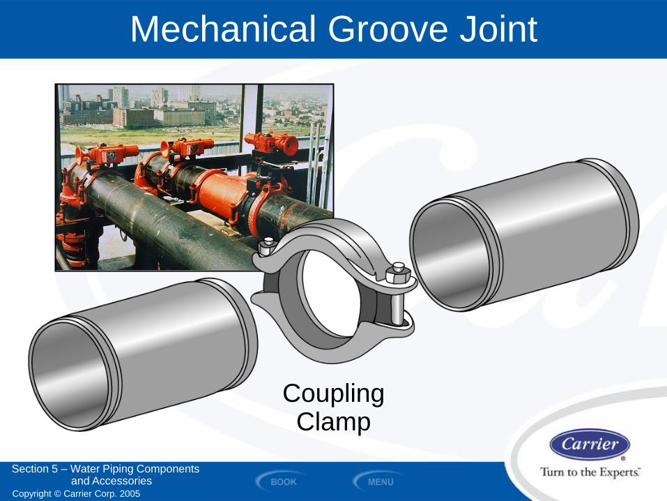
Mechanical Groove Joint
Coupling Clamp
Section 5 – Water Piping Components and Accessories
Copyright © Carrier Corp. 2005
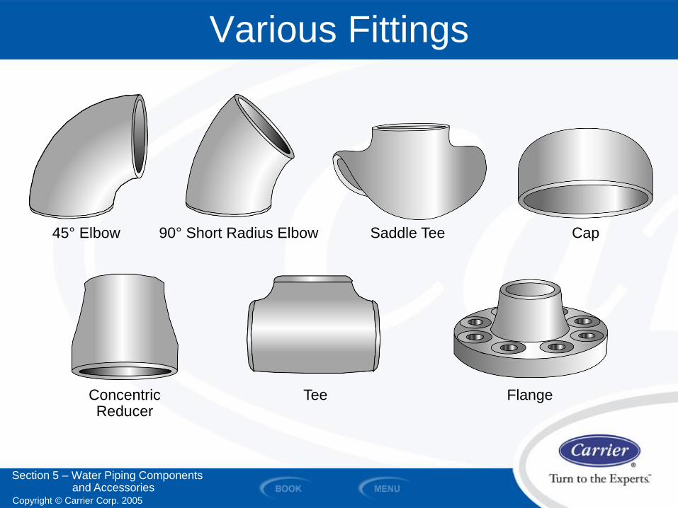
Various Fittings
Tee Concentric Reducer
Flange
90° Short Radius Elbow 45° Elbow Cap Saddle Tee
Section 5 – Water Piping Components and Accessories
Copyright © Carrier Corp. 2005
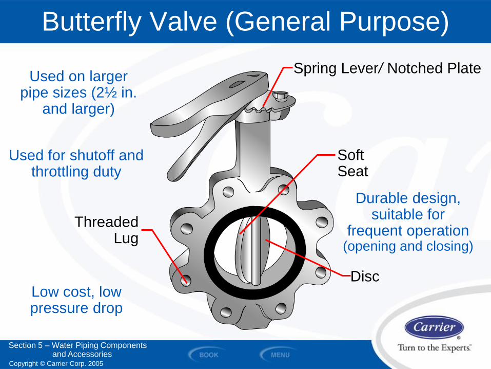
Butterfly Valve (General Purpose)
Spring Lever/ Notched Plate
Threaded Lug
Disc
Soft Seat
Used on larger pipe sizes (2½ in.
and larger)
Low cost, low pressure drop
Used for shutoff and throttling duty
Section 5 – Water Piping Components and Accessories
Durable design, suitable for
frequent operation (opening and closing)
Copyright © Carrier Corp. 2005
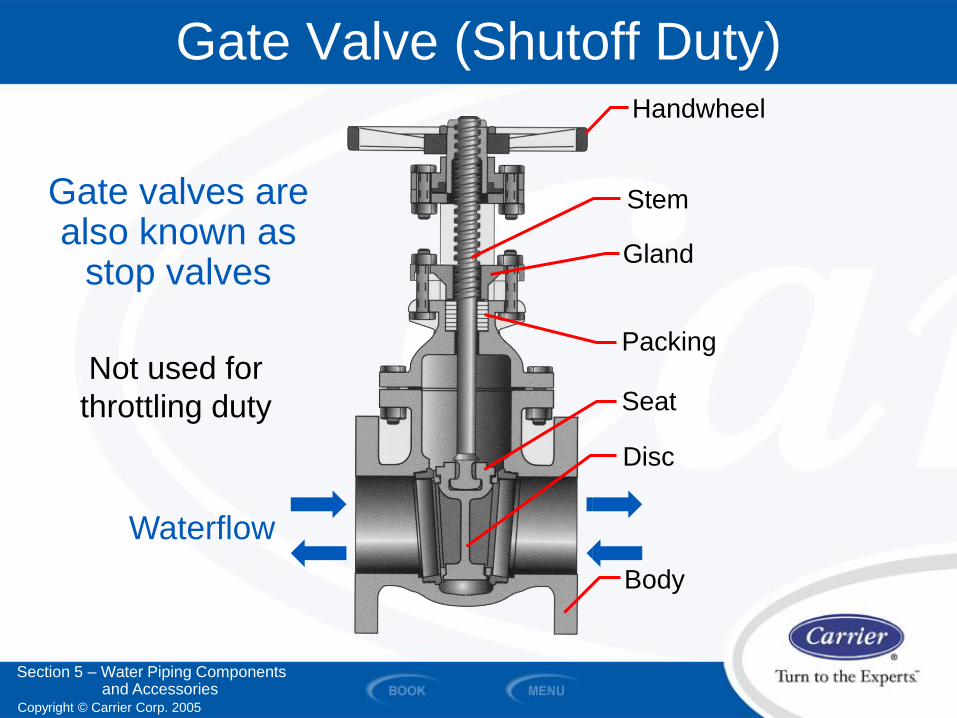
Gate Valve (Shutoff Duty) Handwheel
Stem
Gland
Packing
Disc
Body
Gate valves are also known as
stop valves
Not used for
throttling duty
Waterflow
Section 5 – Water Piping Components and Accessories
Seat
Copyright © Carrier Corp. 2005
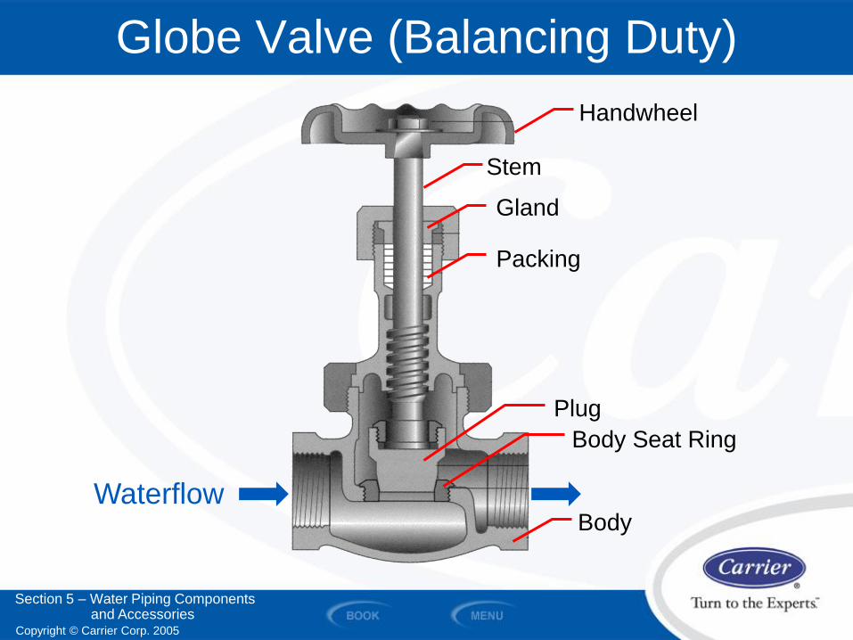
Globe Valve (Balancing Duty)
Handwheel
Stem
Gland
Packing
Plug
Body
Body Seat Ring
Waterflow
Section 5 – Water Piping Components and Accessories
Copyright © Carrier Corp. 2005
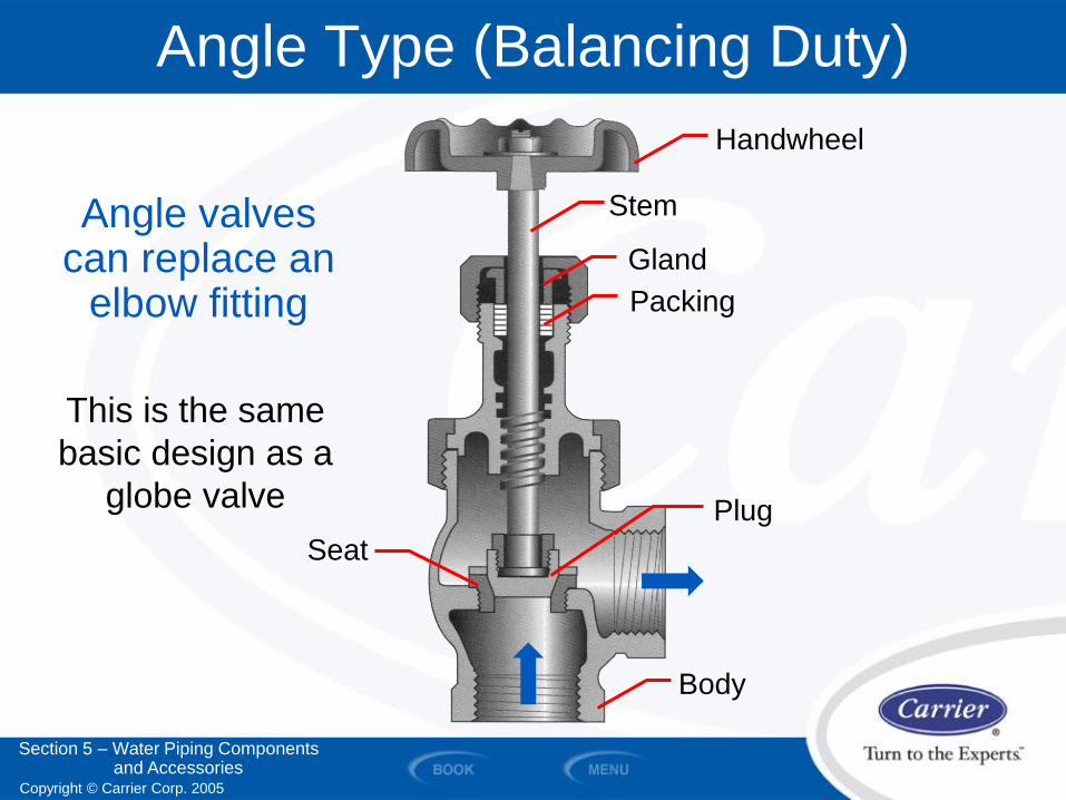
Angle valves can replace an
elbow fitting
Angle Type (Balancing Duty)
Handwheel
Stem
Gland
Packing
Plug
Body
This is the same
basic design as a
globe valve
Section 5 – Water Piping Components and Accessories
Seat
Copyright © Carrier Corp. 2005
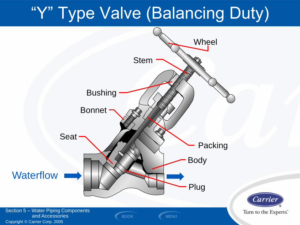
“Y” Type Valve (Balancing Duty)
Wheel
Stem
Bushing
Bonnet
Packing
Body
Plug
Seat
Waterflow
Section 5 – Water Piping Components and Accessories
Copyright © Carrier Corp. 2005
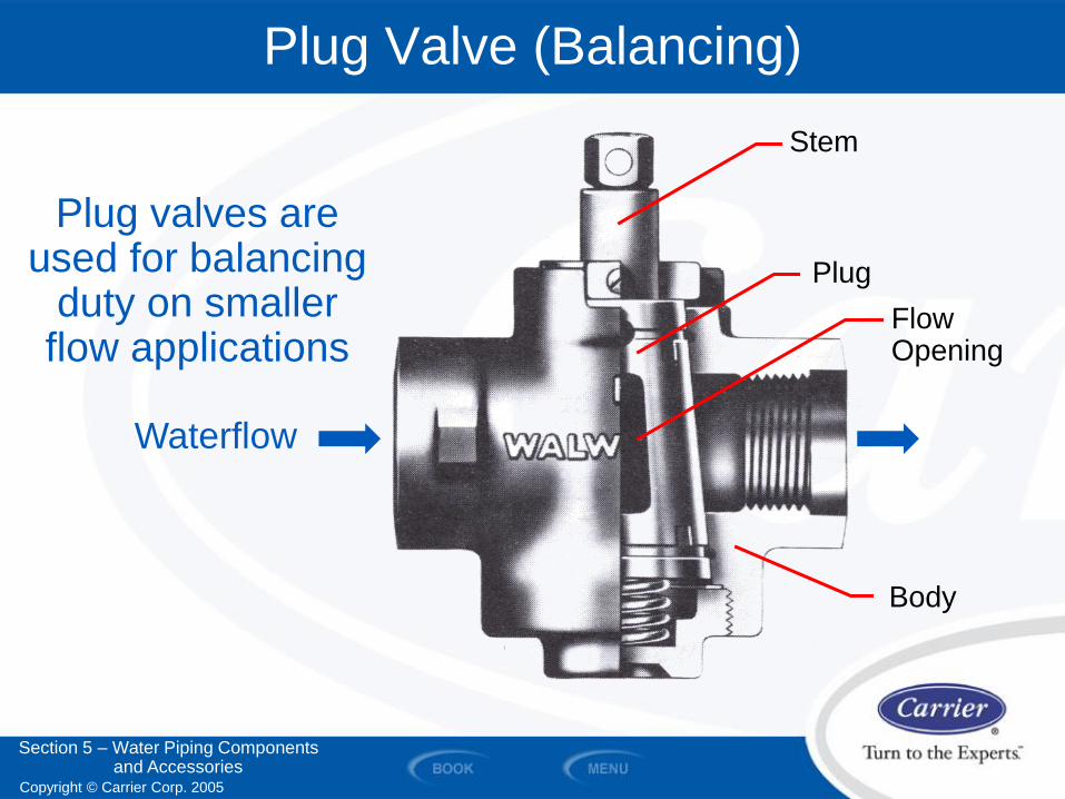
Plug valves are used for balancing
duty on smaller flow applications
Plug Valve (Balancing)
Waterflow
Section 5 – Water Piping Components and Accessories
Stem
Plug
Flow Opening
Body
Copyright © Carrier Corp. 2005
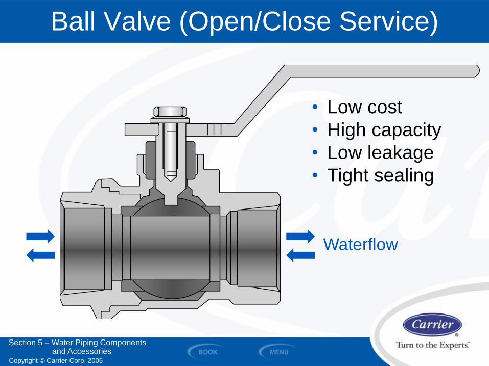
Ball Valve (Open/Close Service)
Waterflow
• Low cost
• High capacity
• Low leakage
• Tight sealing
Section 5 – Water Piping Components and Accessories
Copyright © Carrier Corp. 2005
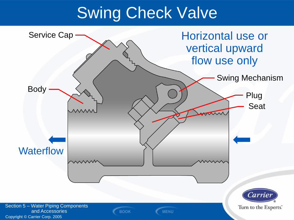
Waterflow
Swing Check Valve
Horizontal use or vertical upward flow use only
Swing Mechanism
Section 5 – Water Piping Components and Accessories
Service Cap
Plug
Seat
Body
Copyright © Carrier Corp. 2005
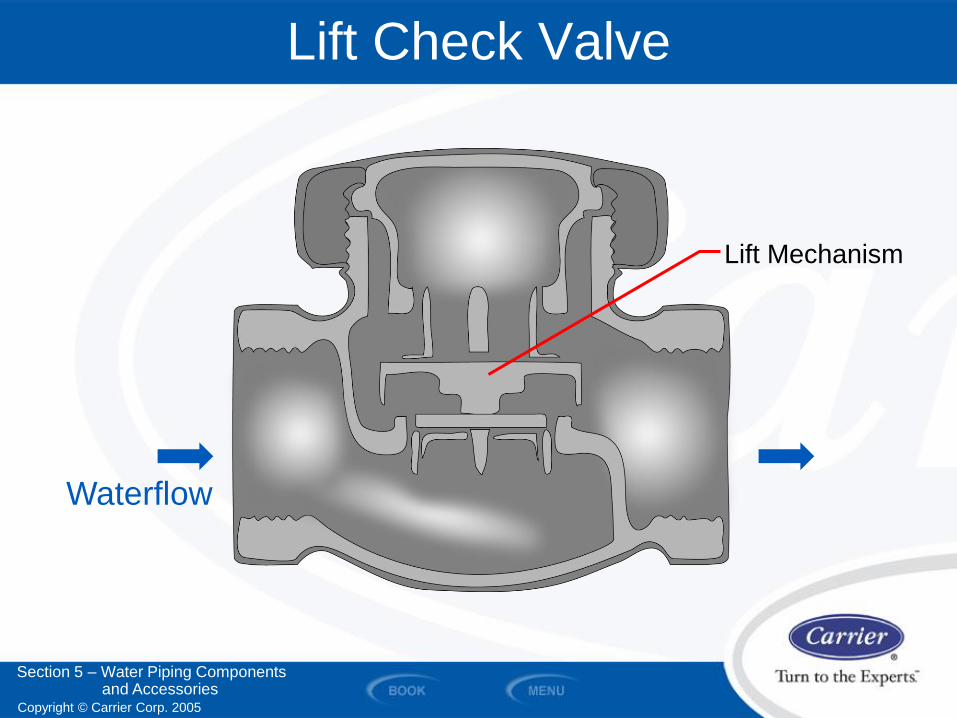
Waterflow
Lift Check Valve
Lift Mechanism
Section 5 – Water Piping Components and Accessories
Copyright © Carrier Corp. 2005
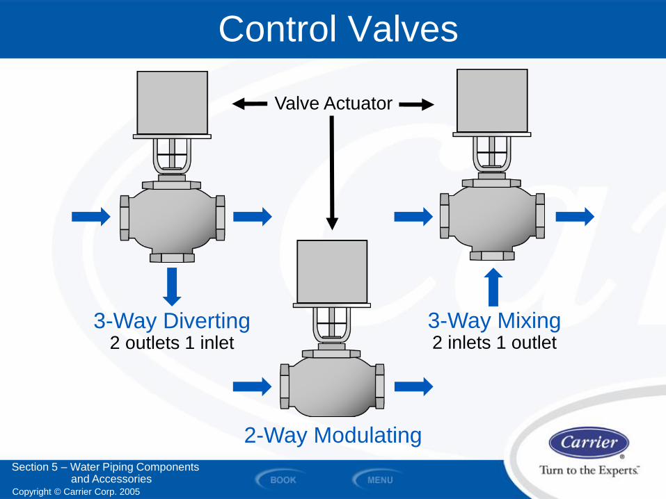
Control Valves
Valve Actuator
2-Way Modulating
3-Way Diverting 2 outlets 1 inlet
3-Way Mixing 2 inlets 1 outlet
Section 5 – Water Piping Components and Accessories
Copyright © Carrier Corp. 2005
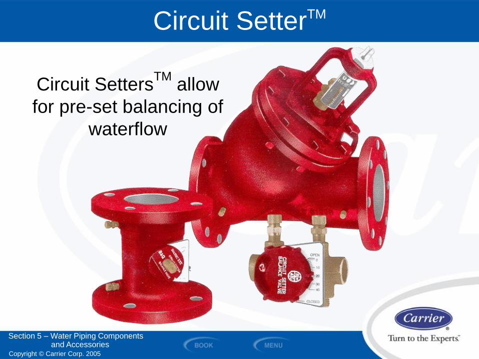
Circuit SetterTM
Circuit SettersTM
allow
for pre-set balancing of
waterflow
Section 5 – Water Piping Components and Accessories
Copyright © Carrier Corp. 2005
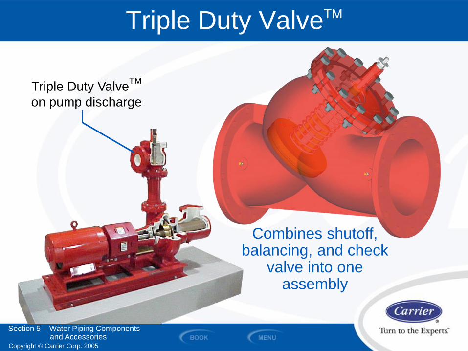
Triple Duty ValveTM
Triple Duty ValveTM
on pump discharge
Combines shutoff, balancing, and check
valve into one assembly
Section 5 – Water Piping Components and Accessories
Copyright © Carrier Corp. 2005
Relative Valve Comparison Chart
Section 5 – Water Piping Components and Accessories
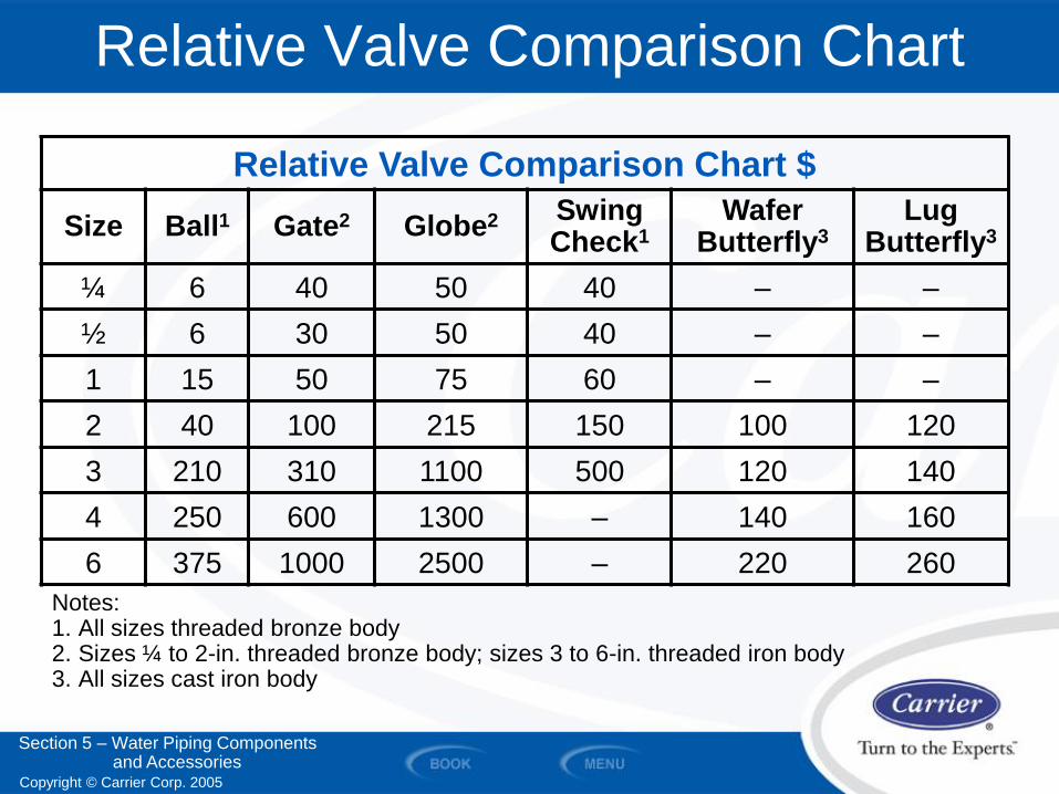
Relative Valve Comparison Chart $
Size Ball1 Gate2 Globe2 Swing Check1
Wafer Butterfly3
Lug Butterfly3
¼ 6 40 50 40 – –
½ 6 30 50 40 – –
1 15 50 75 60 – –
2 40 100 215 150 100 120
3 210 310 1100 500 120 140
4 250 600 1300 – 140 160
6 375 1000 2500 – 220 260
Notes: 1. All sizes threaded bronze body 2. Sizes ¼ to 2-in. threaded bronze body; sizes 3 to 6-in. threaded iron body 3. All sizes cast iron body
Copyright © Carrier Corp. 2005
Hydronic System Components
Section 5 – Water Piping Components and Accessories
• Strainers
• Expansion Tanks
• Air Separators
• Air Vents
• Thermometers, Gauges, Pete’s Plugs
• Pipe Supports
• Volume Tanks
Copyright © Carrier Corp. 2005
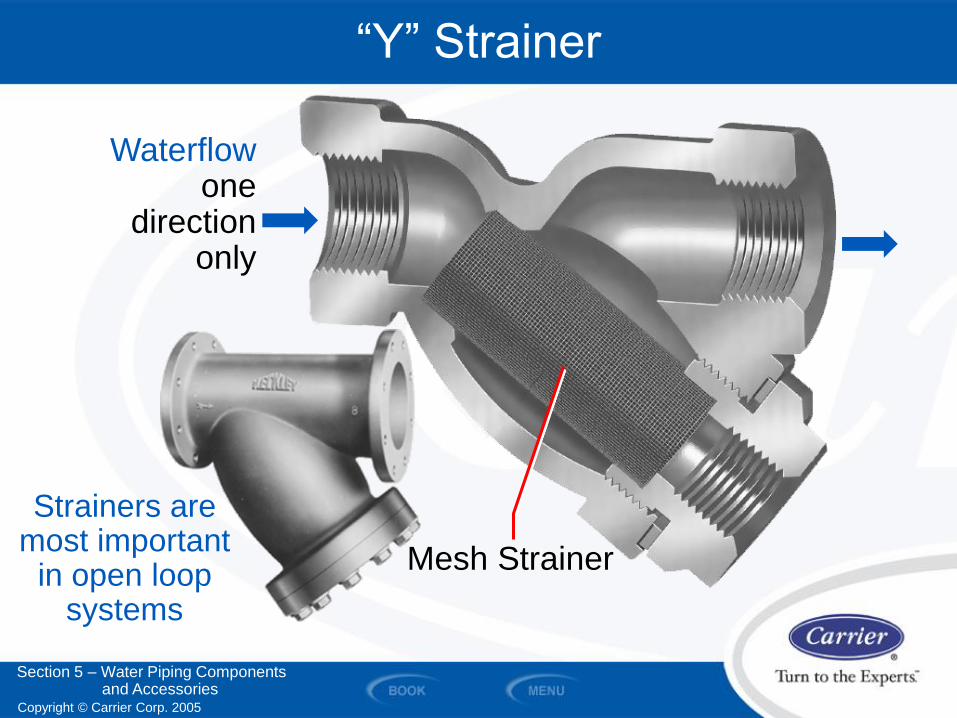
Waterflow one
direction only
“Y” Strainer
Mesh Strainer
Strainers are most important
in open loop systems
Section 5 – Water Piping Components and Accessories
Copyright © Carrier Corp. 2005
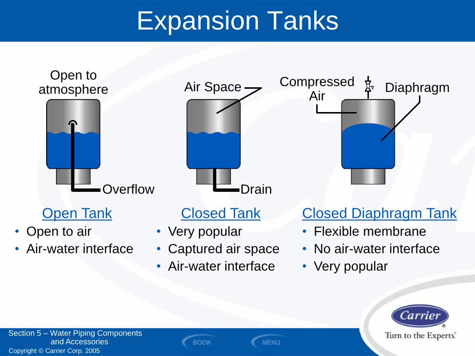
Expansion Tanks
Open Tank
• Open to air
• Air-water interface
Closed Tank
• Very popular
• Captured air space
• Air-water interface
Closed Diaphragm Tank
• Flexible membrane
• No air-water interface
• Very popular
Drain
Air Space
Overflow
Compressed Air
Diaphragm Open to
atmosphere
Section 5 – Water Piping Components and Accessories
Copyright © Carrier Corp. 2005
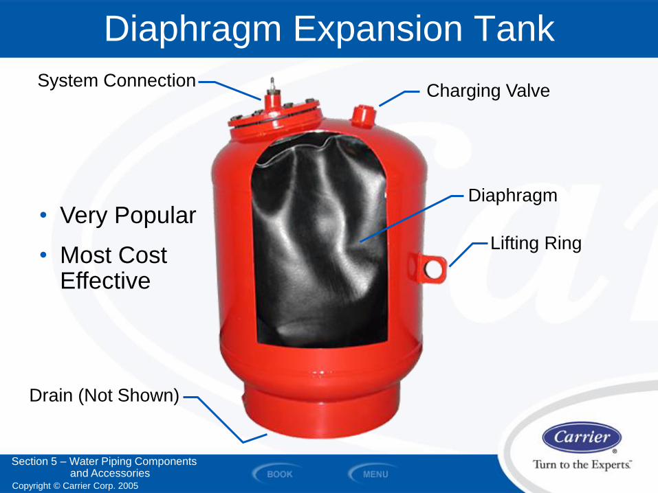
Diaphragm Expansion Tank
Drain (Not Shown)
System Connection Charging Valve
Diaphragm
Lifting Ring
• Very Popular
• Most Cost Effective
Section 5 – Water Piping Components and Accessories
Copyright © Carrier Corp. 2005
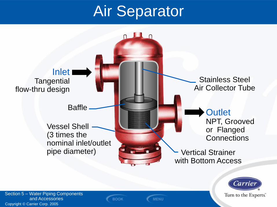
Air Separator
Vertical Strainer with Bottom Access
Baffle
Stainless Steel Air Collector Tube
Vessel Shell (3 times the nominal inlet/outlet pipe diameter)
Inlet Tangential
flow-thru design
Outlet NPT, Grooved or Flanged Connections
Section 5 – Water Piping Components and Accessories
Copyright © Carrier Corp. 2005
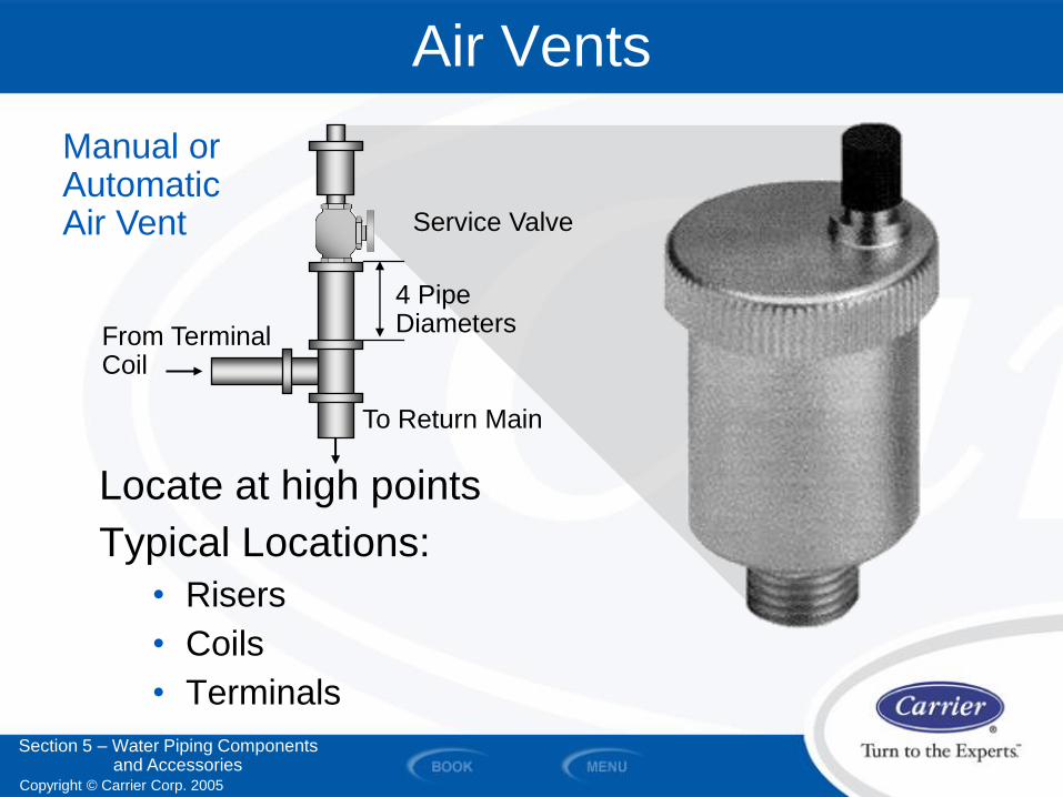
Air Vents
Locate at high points
Typical Locations:
• Risers
• Coils
• Terminals
4 Pipe Diameters
Service Valve
Manual or Automatic Air Vent
To Return Main
From Terminal Coil
Section 5 – Water Piping Components and Accessories
Copyright © Carrier Corp. 2005
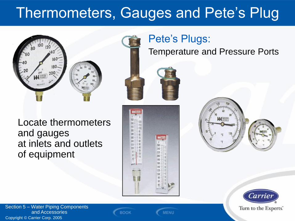
Thermometers, Gauges and Pete’s Plug
Locate thermometers and gauges at inlets and outlets of equipment
Pete’s Plugs: Temperature and Pressure Ports
Section 5 – Water Piping Components and Accessories
Copyright © Carrier Corp. 2005
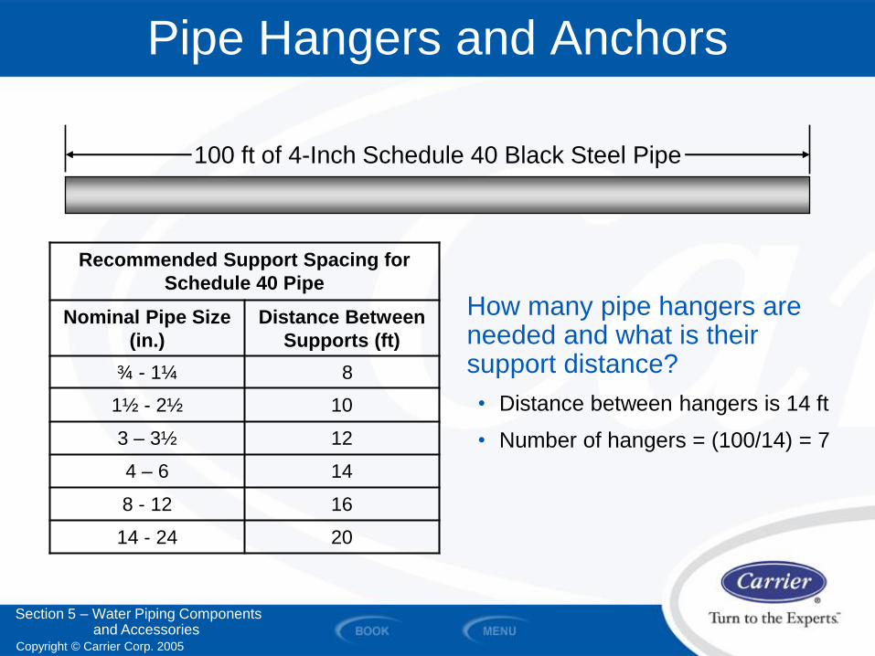
Pipe Hangers and Anchors
How many pipe hangers are needed and what is their support distance?
• Distance between hangers is 14 ft
• Number of hangers = (100/14) = 7
100 ft of 4-Inch Schedule 40 Black Steel Pipe
Recommended Support Spacing for
Schedule 40 Pipe
Nominal Pipe Size
(in.)
Distance Between
Supports (ft)
¾ - 1¼ 8
1½ - 2½ 10
3 – 3½ 12
4 – 6 14
8 - 12 16
14 - 24 20
Section 5 – Water Piping Components and Accessories
Copyright © Carrier Corp. 2005
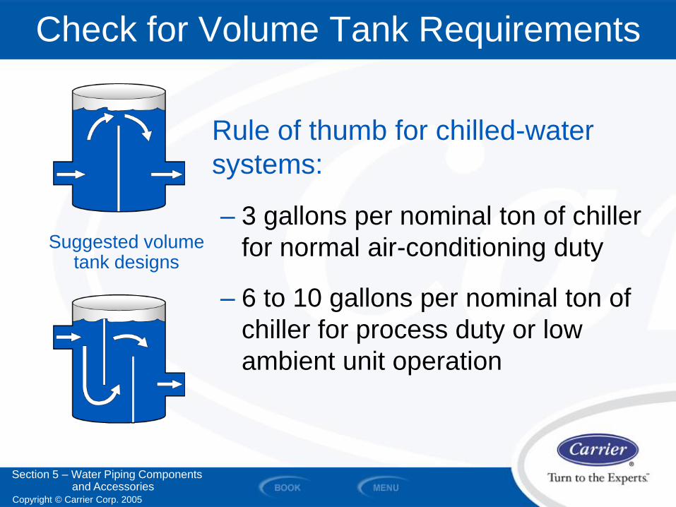
Check for Volume Tank Requirements
Rule of thumb for chilled-water
systems:
– 3 gallons per nominal ton of chiller
for normal air-conditioning duty
– 6 to 10 gallons per nominal ton of
chiller for process duty or low
ambient unit operation
Suggested volume tank designs
Section 5 – Water Piping Components and Accessories

Copyright © Carrier Corp. 2005
SECTION 6
Typical Piping Details at Equipment
WATER PIPING AND PUMPS
Copyright © Carrier Corp. 2005
Typical Piping Details at Equipment
Piping details may vary based on the equipment used and the application. This TDP shows the details of commonly used methods. However, the methods shown do not reflect all specific project requirements. Follow manufacturer’s installation literature.
Section 6 – Typical Piping Details at Equipment
Copyright © Carrier Corp. 2005
Typical Piping Details
At Equipment:
– Water-Cooled Chiller
– Air-Cooled Chiller
– Coil Piping
– Pump Piping
– Expansion Tank and Air Separator
– Parallel and Series Chillers
– Single Chiller System
– Multiple Chiller Systems
– Primary-Secondary System
– Primary-Only Variable Flow System
Section 6 – Typical Piping Details at Equipment
Copyright © Carrier Corp. 2005
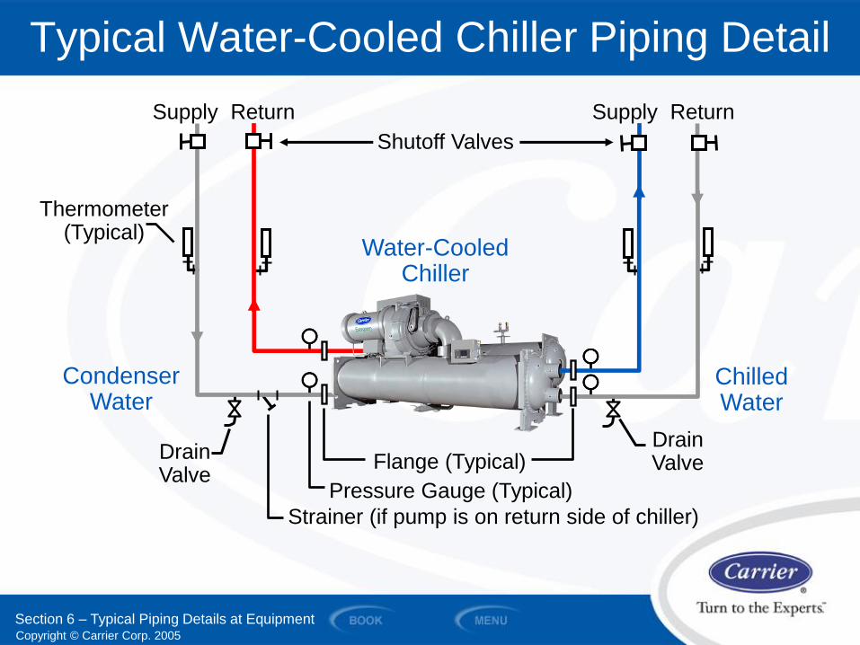
Typical Water-Cooled Chiller Piping Detail
Water-Cooled Chiller
Drain Valve Flange (Typical)
Pressure Gauge (Typical)
Strainer (if pump is on return side of chiller)
Drain Valve
Supply Return
Thermometer (Typical)
Condenser Water
Chilled Water
Shutoff Valves
Section 6 – Typical Piping Details at Equipment
Supply Return
Copyright © Carrier Corp. 2005
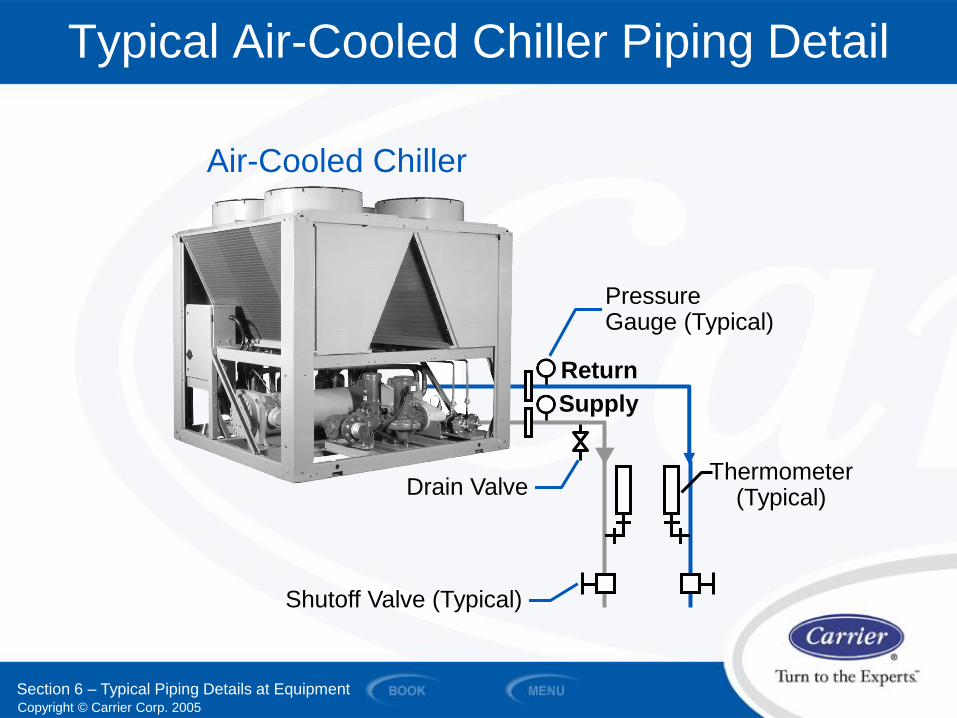
Typical Air-Cooled Chiller Piping Detail
Thermometer (Typical)
Section 6 – Typical Piping Details at Equipment
Drain Valve
Shutoff Valve (Typical)
Pressure Gauge (Typical)
Supply
Return
Air-Cooled Chiller
Copyright © Carrier Corp. 2005
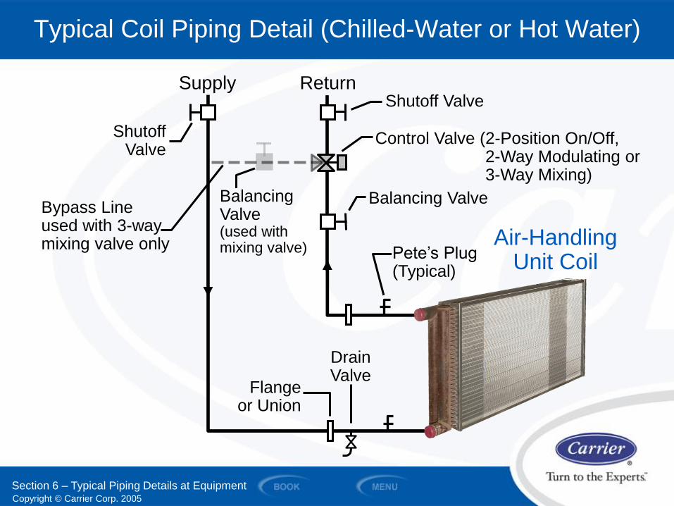
Typical Coil Piping Detail (Chilled-Water or Hot Water)
Section 6 – Typical Piping Details at Equipment
Drain Valve
Supply Return Shutoff Valve
Pete’s Plug (Typical)
Control Valve (2-Position On/Off, 2-Way Modulating or 3-Way Mixing)
Balancing Valve
Shutoff Valve
Balancing Valve (used with mixing valve)
Air-Handling Unit Coil
Flange or Union
Bypass Line used with 3-way mixing valve only
Copyright © Carrier Corp. 2005
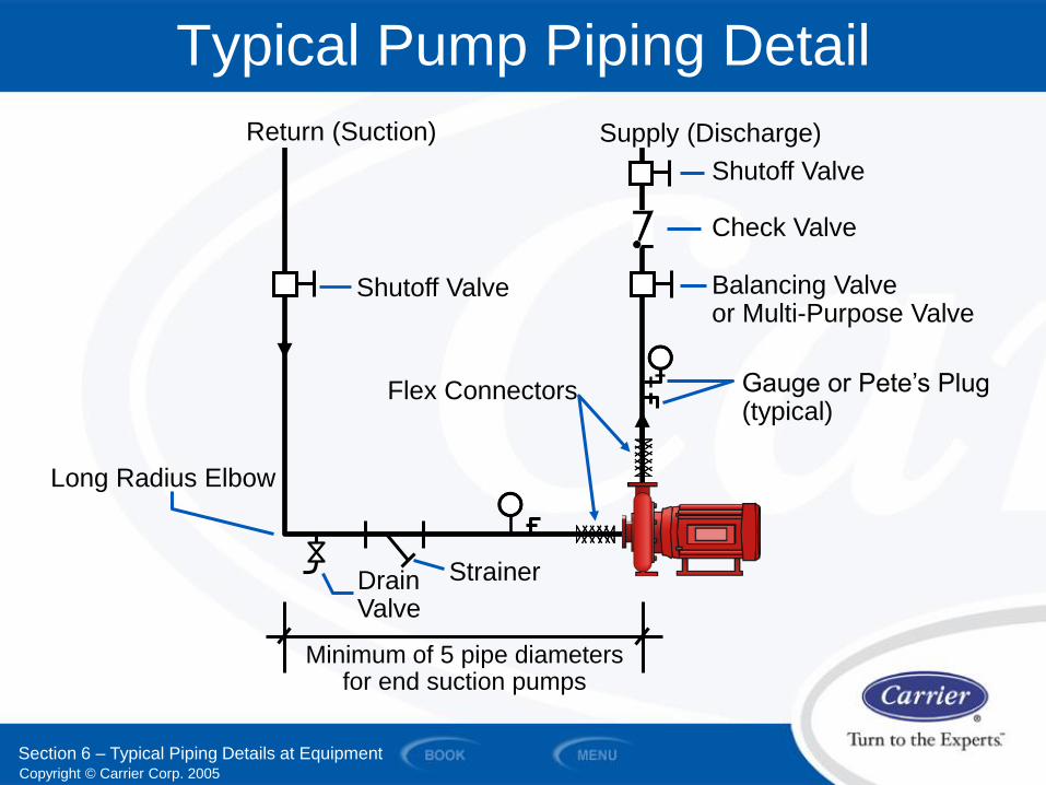
Typical Pump Piping Detail
Drain Valve
Strainer
Shutoff Valve
Return (Suction) Supply (Discharge)
Check Valve
Balancing Valve or Multi-Purpose Valve
Gauge or Pete’s Plug (typical)
Minimum of 5 pipe diameters for end suction pumps
Shutoff Valve
Long Radius Elbow
Flex Connectors
Section 6 – Typical Piping Details at Equipment
Copyright © Carrier Corp. 2005
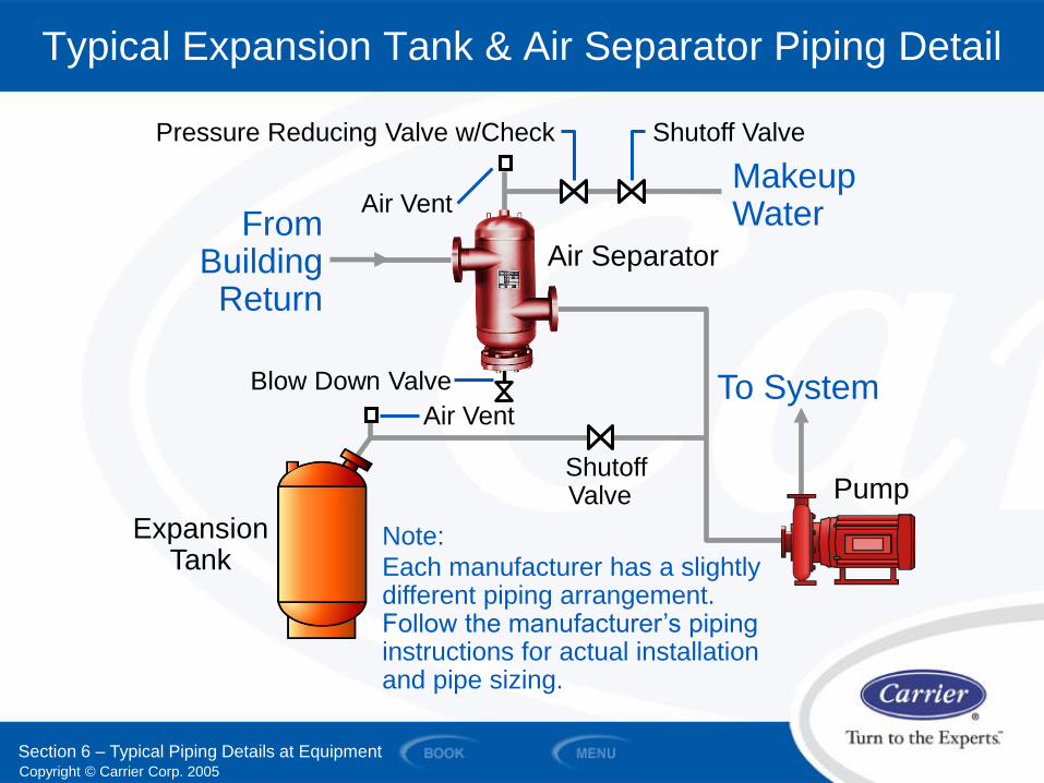
Typical Expansion Tank & Air Separator Piping Detail
Shutoff Valve
Expansion Tank
From Building Return
Air Separator
Makeup Water Air Vent
Blow Down Valve
Air Vent
Pressure Reducing Valve w/Check Shutoff Valve
Note:
Each manufacturer has a slightly different piping arrangement. Follow the manufacturer’s piping instructions for actual installation and pipe sizing.
To System
Pump
Section 6 – Typical Piping Details at Equipment

Copyright © Carrier Corp. 2005
SECTION 7
System Piping Arrangements
WATER PIPING AND PUMPS
Copyright © Carrier Corp. 2005
System Piping Arrangements
Section 7 – System Piping Arrangements
System piping arrangements may vary based on the equipment used and the application. The piping arrangements shown are schematics of commonly used methods. However, the methods shown do not reflect all specific project requirements. Follow manufacturer’s installation literature.
Copyright © Carrier Corp. 2005
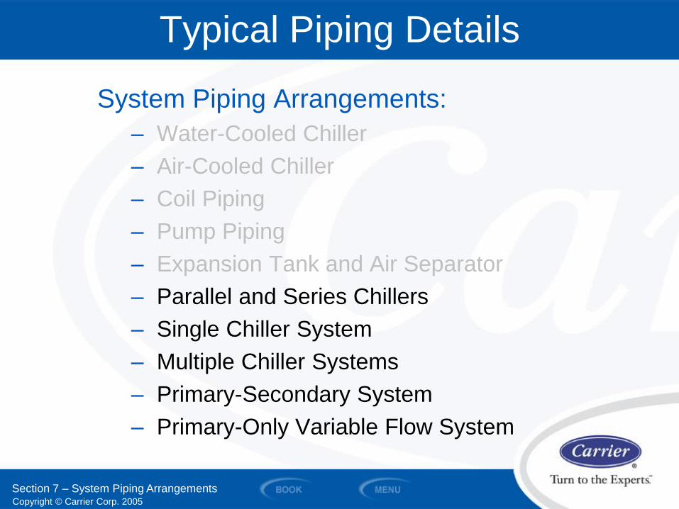
Typical Piping Details
System Piping Arrangements:
– Water-Cooled Chiller
– Air-Cooled Chiller
– Coil Piping
– Pump Piping
– Expansion Tank and Air Separator
– Parallel and Series Chillers
– Single Chiller System
– Multiple Chiller Systems
– Primary-Secondary System
– Primary-Only Variable Flow System
Section 7 – System Piping Arrangements
Copyright © Carrier Corp. 2005
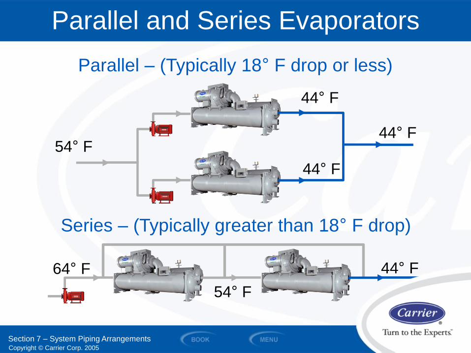
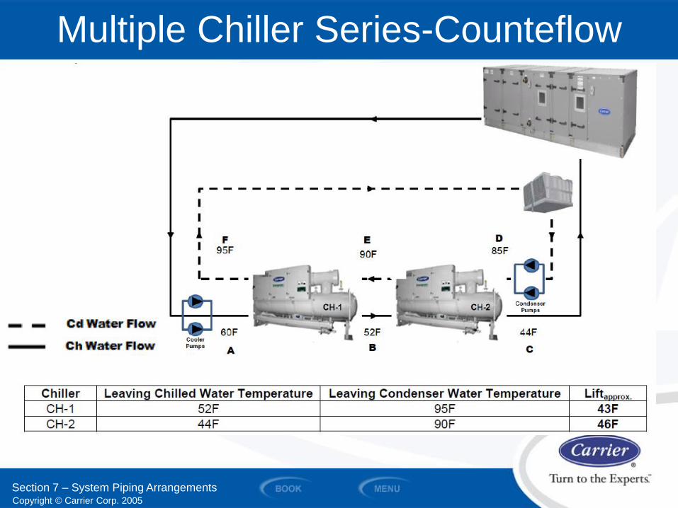
64° F
54° F
44° F
Series – (Typically greater than 18° F drop)
54° F
44° F
44° F
44° F
Parallel – (Typically 18° F drop or less)
Section 7 – System Piping Arrangements
Parallel and Series Evaporators
Copyright © Carrier Corp. 2005
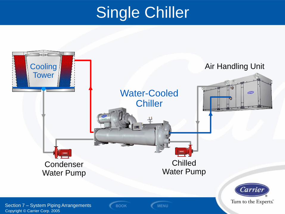
Single Chiller
Air Handling Unit
Chilled Water Pump
Water-Cooled
Chiller
Condenser Water Pump
Cooling Tower
Section 7 – System Piping Arrangements
Cooling Tower
Copyright © Carrier Corp. 2005
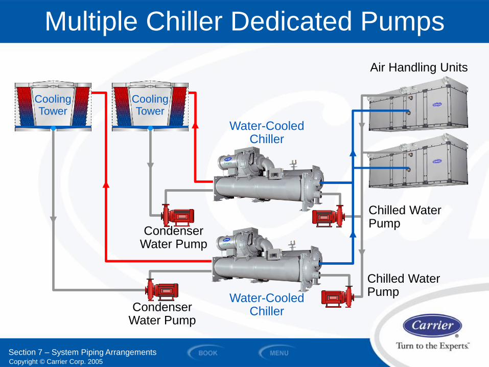
Condenser Water Pump
Condenser Water Pump
Multiple Chiller Dedicated Pumps
Air Handling Units
Cooling Tower
Cooling Tower
Water-Cooled Chiller
Water-Cooled Chiller
Chilled Water Pump
Chilled Water Pump
Section 7 – System Piping Arrangements
Copyright © Carrier Corp. 2005
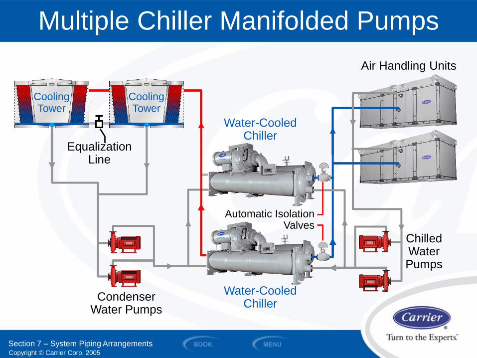
Condenser Water Pumps
Cooling Tower
Water-Cooled Chiller
Chilled Water Pumps
Cooling Tower
Equalization Line
Multiple Chiller Manifolded Pumps
Automatic Isolation Valves
Water-Cooled Chiller
Section 7 – System Piping Arrangements
Air Handling Units
Copyright © Carrier Corp. 2005
Multiple Chiller Series-Counteflow
Section 7 – System Piping Arrangements
Copyright © Carrier Corp. 2005
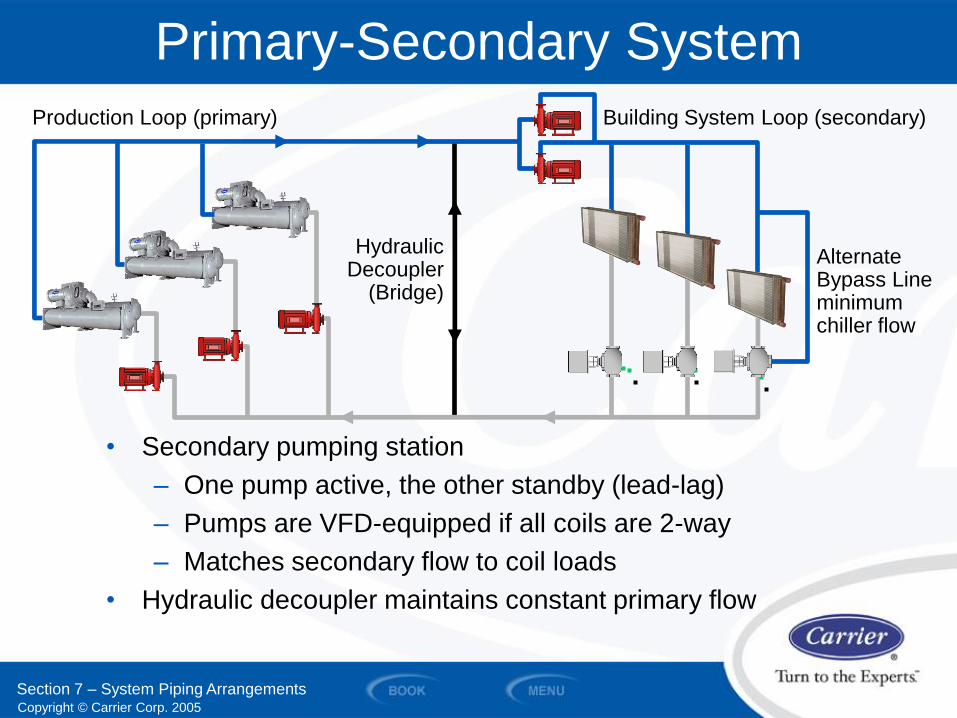
Primary-Secondary System
• Secondary pumping station
– One pump active, the other standby (lead-lag)
– Pumps are VFD-equipped if all coils are 2-way
– Matches secondary flow to coil loads
• Hydraulic decoupler maintains constant primary flow
Hydraulic Decoupler
(Bridge)
Production Loop (primary) Building System Loop (secondary)
Section 7 – System Piping Arrangements
Alternate Bypass Line minimum chiller flow
Copyright © Carrier Corp. 2005
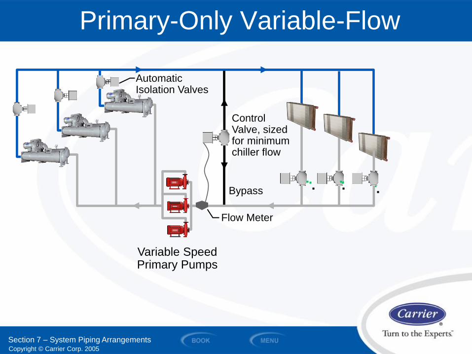
Primary-Only Variable-Flow
Flow Meter
Control Valve, sized for minimum chiller flow
Automatic Isolation Valves
Variable Speed Primary Pumps
Bypass
Section 7 – System Piping Arrangements
Copyright © Carrier Corp. 2005
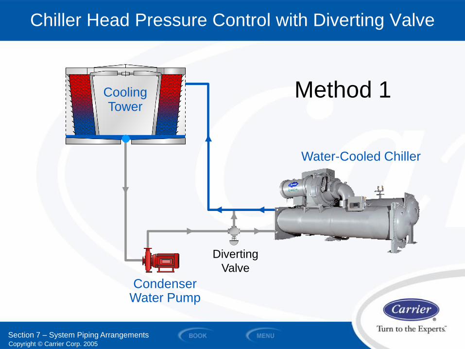
Water-Cooled Chiller
Condenser Water Pump
Cooling Tower
Chiller Head Pressure Control with Diverting Valve
Section 7 – System Piping Arrangements
Method 1
Diverting
Valve
Copyright © Carrier Corp. 2005
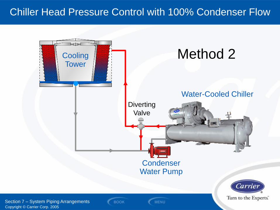
Water-Cooled Chiller
Cooling Tower
Chiller Head Pressure Control with 100% Condenser Flow
Condenser Water Pump
Section 7 – System Piping Arrangements
Diverting
Valve
Method 2
Copyright © Carrier Corp. 2005
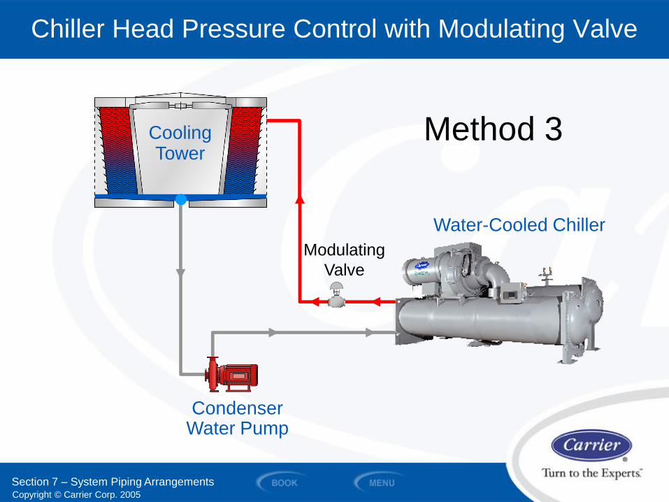
Water-Cooled Chiller
Condenser Water Pump
Cooling Tower
Chiller Head Pressure Control with Modulating Valve
Section 7 – System Piping Arrangements
Method 3
Modulating
Valve

Copyright © Carrier Corp. 2005
SECTION 8
Pump Basics and Types of Pumps
WATER PIPING AND PUMPS
Copyright © Carrier Corp. 2005
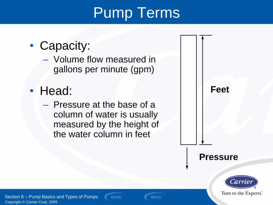
• Capacity: – Volume flow measured in
gallons per minute (gpm)
• Head: – Pressure at the base of a
column of water is usually measured by the height of the water column in feet
Pump Terms
Feet
Pressure
Section 8 – Pump Basics and Types of Pumps
Copyright © Carrier Corp. 2005
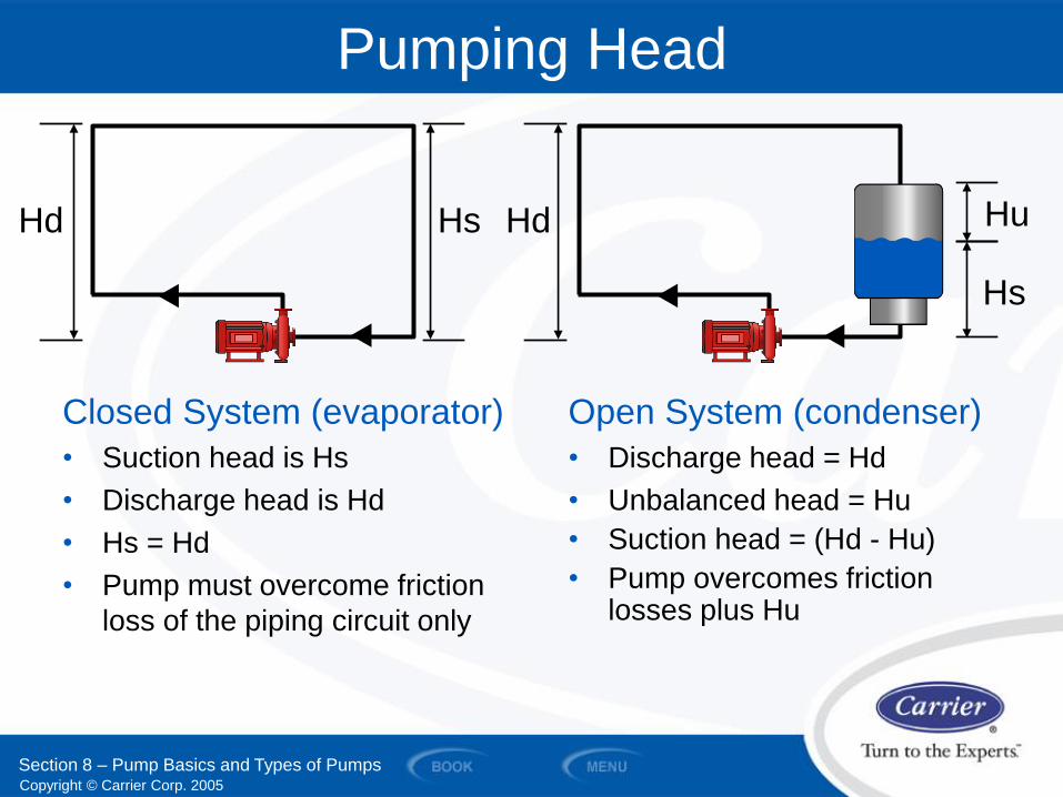
Closed System (evaporator)
• Suction head is Hs
• Discharge head is Hd
• Hs = Hd
• Pump must overcome friction
loss of the piping circuit only
Pumping Head
Open System (condenser)
• Discharge head = Hd
• Unbalanced head = Hu
• Suction head = (Hd - Hu)
• Pump overcomes friction losses plus Hu
Hd Hs Hd Hu
Section 8 – Pump Basics and Types of Pumps
Hs
Copyright © Carrier Corp. 2005
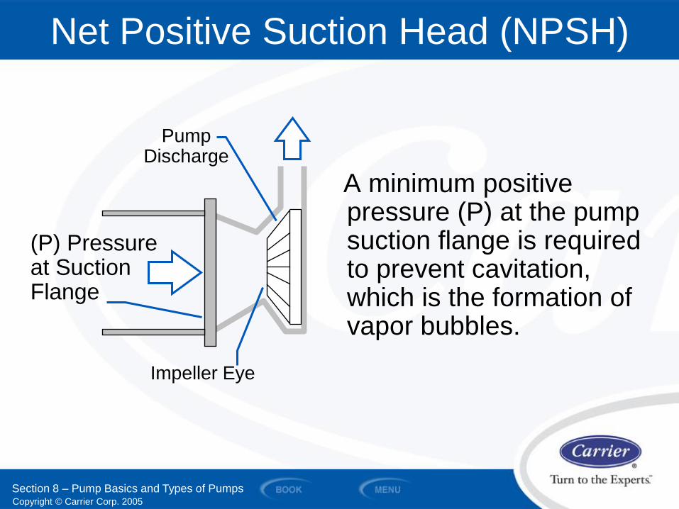
A minimum positive pressure (P) at the pump suction flange is required to prevent cavitation, which is the formation of vapor bubbles.
Net Positive Suction Head (NPSH)
(P) Pressure at Suction Flange
Impeller Eye
Pump Discharge
Section 8 – Pump Basics and Types of Pumps
Copyright © Carrier Corp. 2005
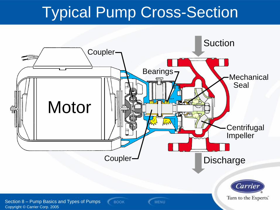
Typical Pump Cross-Section
Section 8 – Pump Basics and Types of Pumps
Motor
Coupler
Bearings Mechanical Seal
Coupler
Centrifugal Impeller
Discharge
Suction
Copyright © Carrier Corp. 2005
Flow - gpm
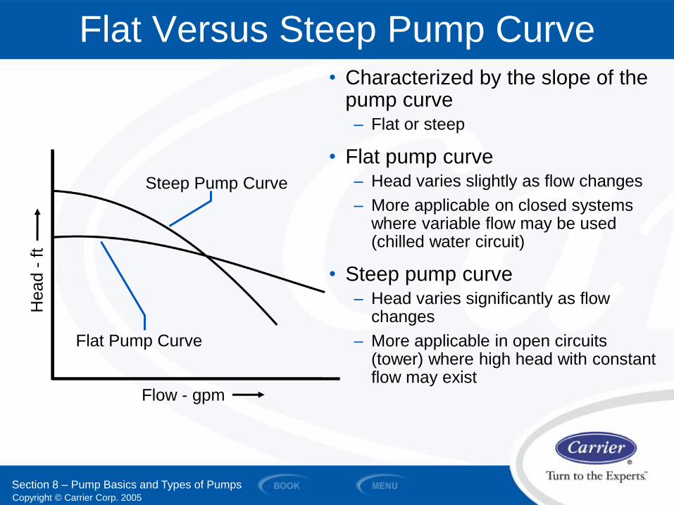
Flat Versus Steep Pump Curve
Steep Pump Curve
Flat Pump Curve
• Characterized by the slope of the pump curve – Flat or steep
• Flat pump curve – Head varies slightly as flow changes
– More applicable on closed systems where variable flow may be used (chilled water circuit)
• Steep pump curve – Head varies significantly as flow
changes
– More applicable in open circuits (tower) where high head with constant flow may exist
Section 8 – Pump Basics and Types of Pumps
Head -
ft
Copyright © Carrier Corp. 2005
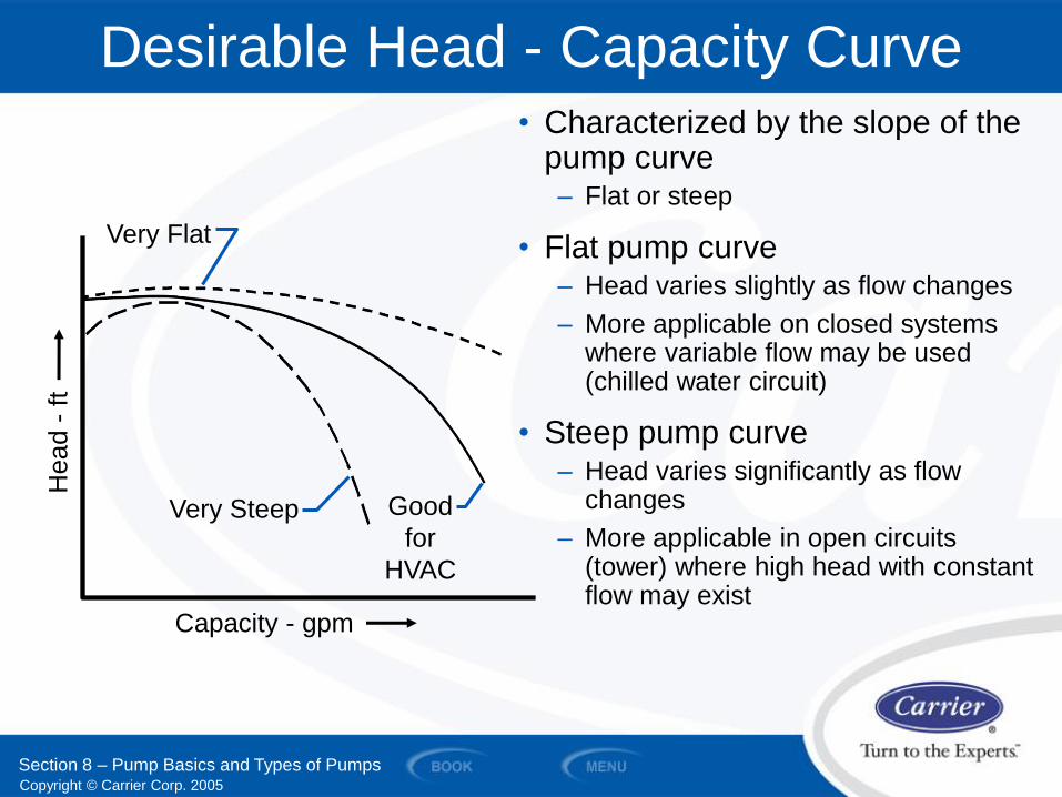
Desirable Head - Capacity Curve
Capacity - gpm
Head -
ft
Very Steep
Very Flat
Good
for
HVAC
• Characterized by the slope of the pump curve – Flat or steep
• Flat pump curve – Head varies slightly as flow changes
– More applicable on closed systems where variable flow may be used (chilled water circuit)
• Steep pump curve – Head varies significantly as flow
changes
– More applicable in open circuits (tower) where high head with constant flow may exist
Section 8 – Pump Basics and Types of Pumps
Copyright © Carrier Corp. 2005
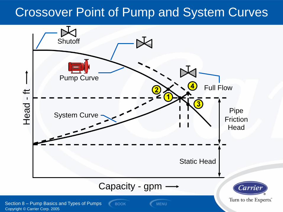
Crossover Point of Pump and System Curves
System Curve
Pump Curve
Full Flow
Static Head
Capacity - gpm
Shutoff
Head -
ft
Pipe
Friction Head
Section 8 – Pump Basics and Types of Pumps
Copyright © Carrier Corp. 2005
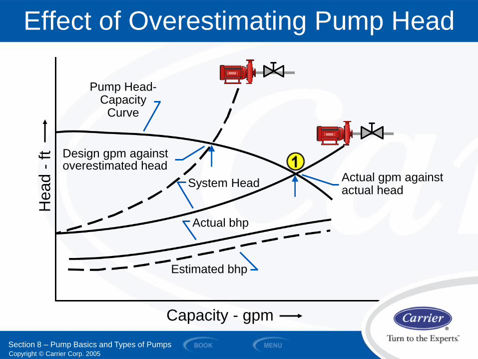
Effect of Overestimating Pump Head
System Head
Pump Head- Capacity
Curve
Actual gpm against actual head
Actual bhp
Estimated bhp
Design gpm against overestimated head
Capacity - gpm
Head -
ft
Section 8 – Pump Basics and Types of Pumps
Copyright © Carrier Corp. 2005
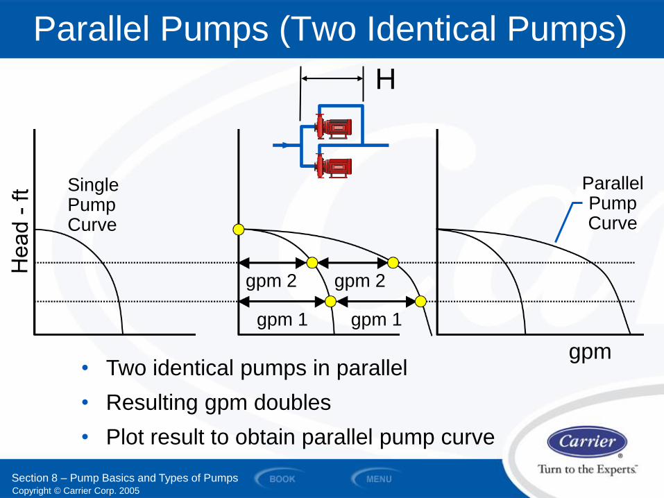
Parallel Pumps (Two Identical Pumps)
H
• Two identical pumps in parallel
• Resulting gpm doubles
• Plot result to obtain parallel pump curve
gpm 2
gpm 1 gpm 1
gpm 2
Parallel Pump Curve
Single Pump Curve
gpm
Section 8 – Pump Basics and Types of Pumps

Copyright © Carrier Corp. 2005
Series Pumps (Two Identical Pumps)
H2 H1
gpm
Single Pump Curve
Head 1
Head 1
Head 2
Head 2
Series Pump Curve
Section 8 – Pump Basics and Types of Pumps
• Two identical pumps in series
• Resulting head doubles
• Plot result to obtain series pump curve
Copyright © Carrier Corp. 2005
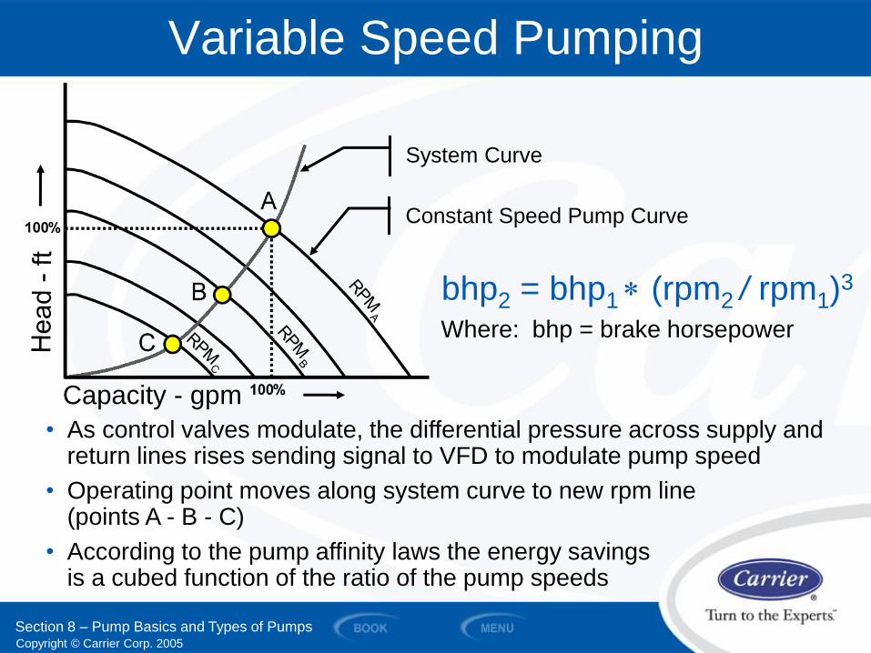
Variable Speed Pumping
Capacity - gpm
• As control valves modulate, the differential pressure across supply and return lines rises sending signal to VFD to modulate pump speed
• Operating point moves along system curve to new rpm line (points A - B - C)
• According to the pump affinity laws the energy savings is a cubed function of the ratio of the pump speeds
Constant Speed Pump Curve
System Curve
bhp2 = bhp1 (rpm2 / rpm1)3
Where: bhp = brake horsepower
Section 8 – Pump Basics and Types of Pumps
Copyright © Carrier Corp. 2005
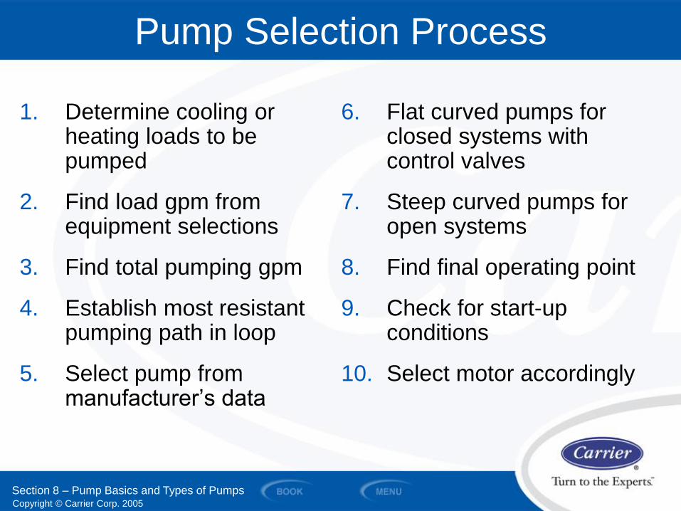
1. Determine cooling or heating loads to be pumped
2. Find load gpm from equipment selections
3. Find total pumping gpm
4. Establish most resistant pumping path in loop
5. Select pump from manufacturer’s data
Pump Selection Process
6. Flat curved pumps for closed systems with control valves
7. Steep curved pumps for open systems
8. Find final operating point
9. Check for start-up conditions
10. Select motor accordingly
Section 8 – Pump Basics and Types of Pumps
Copyright © Carrier Corp. 2005
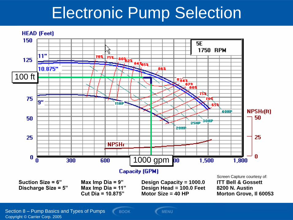
Electronic Pump Selection
Suction Size = 6” Max Imp Dia = 9” Design Capacity = 1000.0 ITT Bell & Gossett Discharge Size = 5” Max Imp Dia = 11” Design Head = 100.0 Feet 8200 N. Austin Cut Dia = 10.875” Motor Size = 40 HP Morton Grove, Il 60053
Section 8 – Pump Basics and Types of Pumps
100 ft
1000 gpm
Screen Capture courtesy of:
Copyright © Carrier Corp. 2005
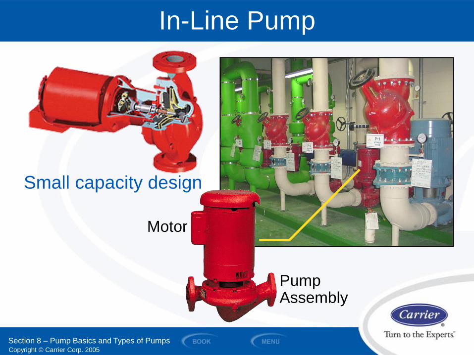
In-Line Pump
Motor
Pump Assembly
Small capacity design
Section 8 – Pump Basics and Types of Pumps
Copyright © Carrier Corp. 2005
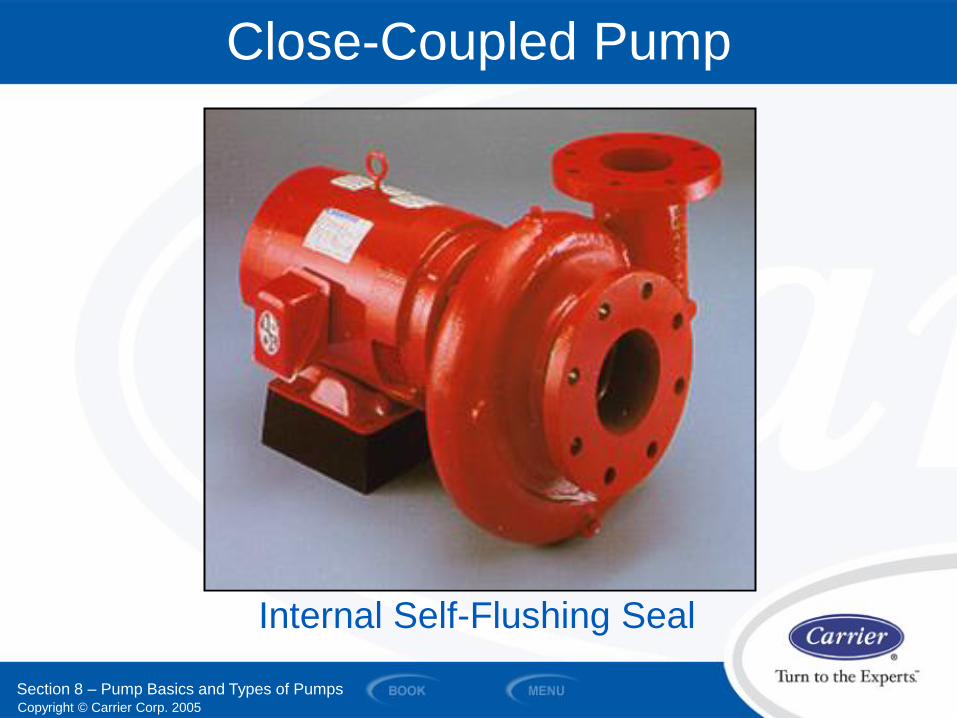
Close-Coupled Pump
Internal Self-Flushing Seal
Section 8 – Pump Basics and Types of Pumps
Copyright © Carrier Corp. 2005
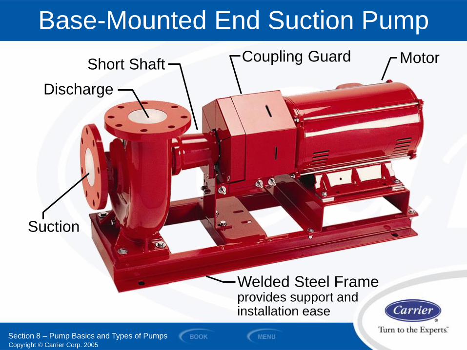
Base-Mounted End Suction Pump
Discharge
Short Shaft Coupling Guard Motor
Suction
Welded Steel Frame provides support and installation ease
Section 8 – Pump Basics and Types of Pumps
Copyright © Carrier Corp. 2005
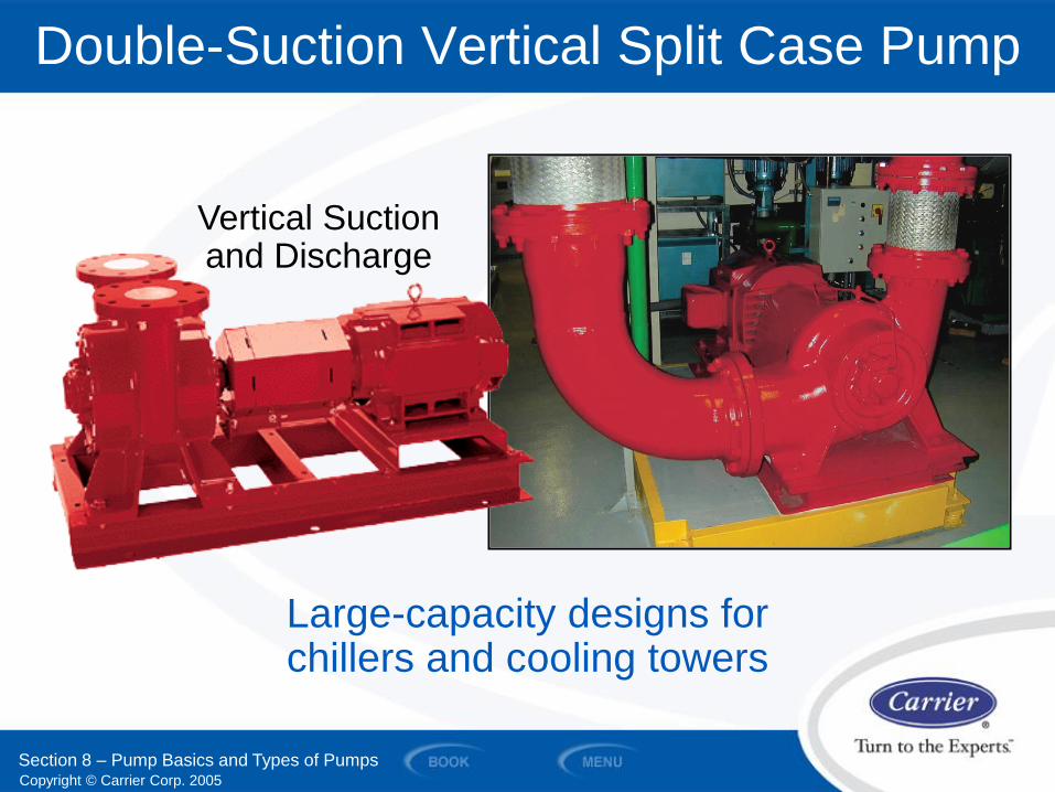
Double-Suction Vertical Split Case Pump
Vertical Suction and Discharge
Large-capacity designs for chillers and cooling towers
Section 8 – Pump Basics and Types of Pumps
Copyright © Carrier Corp. 2005
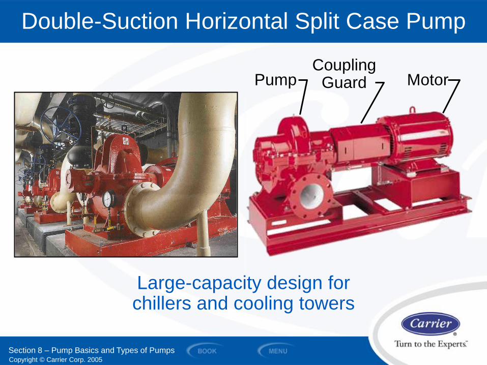
Double-Suction Horizontal Split Case Pump
Pump Coupling
Guard Motor
Large-capacity design for chillers and cooling towers
Section 8 – Pump Basics and Types of Pumps
Copyright © Carrier Corp. 2005
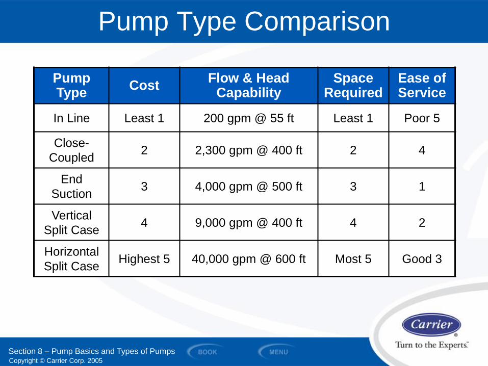
Pump Type Comparison
Pump Type
Cost Flow & Head
Capability Space
Required Ease of Service
In Line Least 1 200 gpm @ 55 ft Least 1 Poor 5
Close-
Coupled 2 2,300 gpm @ 400 ft 2 4
End
Suction 3 4,000 gpm @ 500 ft 3 1
Vertical
Split Case 4 9,000 gpm @ 400 ft 4 2
Horizontal
Split Case Highest 5 40,000 gpm @ 600 ft Most 5 Good 3
Section 8 – Pump Basics and Types of Pumps

Copyright © Carrier Corp. 2005
SECTION 9
Pump Sizing and Pump Selection Example
WATER PIPING AND PUMPS
Copyright © Carrier Corp. 2005
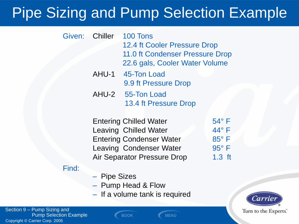
Pipe Sizing and Pump Selection Example
Given: Chiller 100 Tons
12.4 ft Cooler Pressure Drop
11.0 ft Condenser Pressure Drop
22.6 gals, Cooler Water Volume
AHU-1 45-Ton Load
9.9 ft Pressure Drop
AHU-2 55-Ton Load
13.4 ft Pressure Drop
Entering Chilled Water 54° F
Leaving Chilled Water 44° F
Entering Condenser Water 85° F
Leaving Condenser Water 95° F
Air Separator Pressure Drop 1.3 ft
Find: – Pipe Sizes
– Pump Head & Flow
– If a volume tank is required
Section 9 – Pump Sizing and Pump Selection Example
Copyright © Carrier Corp. 2005
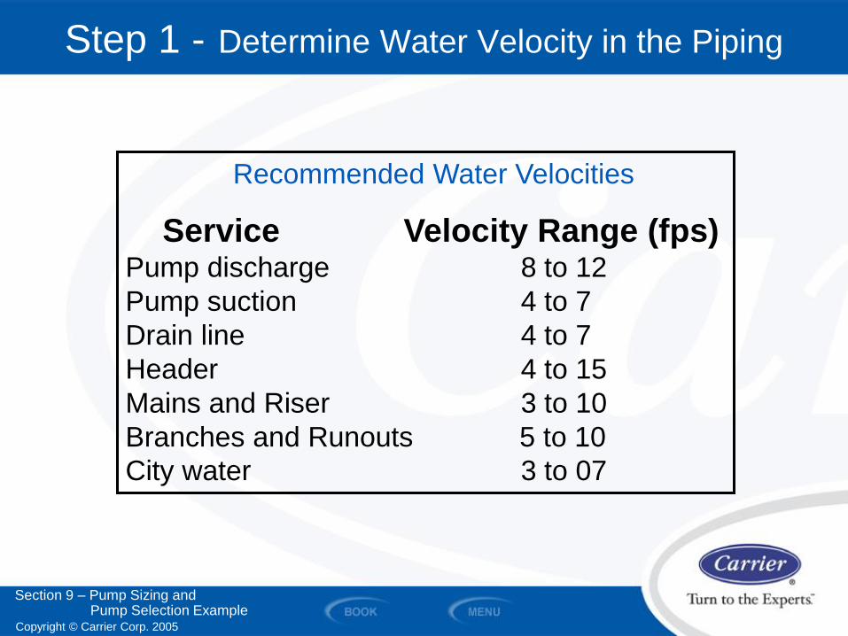
Recommended Water Velocities
Service Velocity Range (fps)
Pump discharge 8 to 12
Pump suction 4 to 7
Drain line 4 to 7
Header 4 to 15
Mains and Riser 3 to 10
Branches and Runouts 5 to 10
City water 3 to 07
Step 1 - Determine Water Velocity in the Piping
Section 9 – Pump Sizing and Pump Selection Example
Copyright © Carrier Corp. 2005
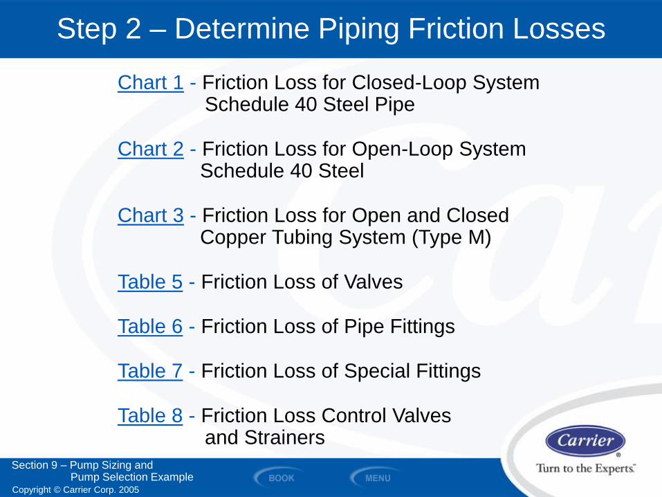
Step 2 – Determine Piping Friction Losses
Section 9 – Pump Sizing and Pump Selection Example
Chart 1 - Friction Loss for Closed-Loop System Schedule 40 Steel Pipe
Chart 2 - Friction Loss for Open-Loop System Schedule 40 Steel
Chart 3 - Friction Loss for Open and Closed Copper Tubing System (Type M)
Table 5 - Friction Loss of Valves
Table 6 - Friction Loss of Pipe Fittings
Table 7 - Friction Loss of Special Fittings
Table 8 - Friction Loss Control Valves and Strainers
Copyright © Carrier Corp. 2005
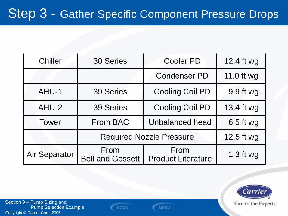
Step 3 - Gather Specific Component Pressure Drops
Chiller 30 Series Cooler PD 12.4 ft wg
Condenser PD 11.0 ft wg
AHU-1 39 Series Cooling Coil PD 9.9 ft wg
AHU-2 39 Series Cooling Coil PD 13.4 ft wg
Tower From BAC Unbalanced head 6.5 ft wg
Required Nozzle Pressure 12.5 ft wg
Air Separator From
Bell and Gossett From
Product Literature 1.3 ft wg
Section 9 – Pump Sizing and Pump Selection Example
Copyright © Carrier Corp. 2005
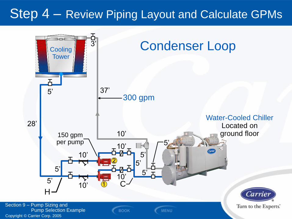
Step 4 – Review Piping Layout and Calculate GPMs
Cooling Tower
37’
28’
5’
3’
5’
5’
5’ 10’
10’
10’
10’ 5’
5’
C
5’
H
Condenser Loop
300 gpm
Water-Cooled Chiller Located on ground floor
Section 9 – Pump Sizing and Pump Selection Example
150 gpm per pump
10’
Copyright © Carrier Corp. 2005
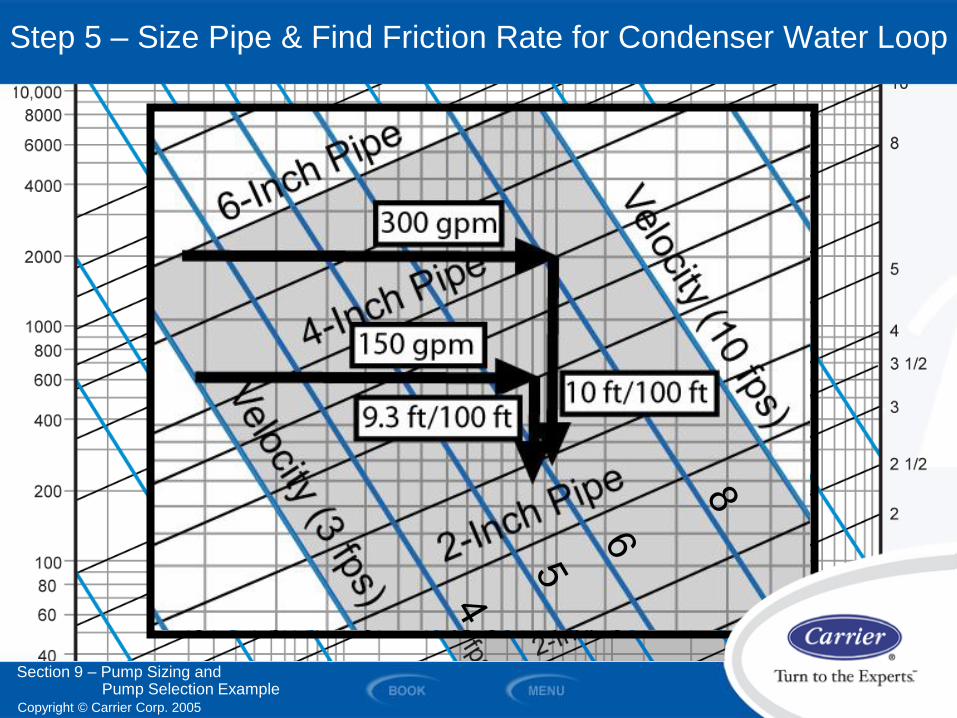
Using Chart 2, size the pipe and find
the friction rate per 100 ft
Step 5 – Size Pipe & Find Friction Rate for Condenser Water Loop
Section 9 – Pump Sizing and Pump Selection Example
Copyright © Carrier Corp. 2005
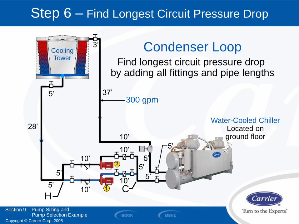
Step 6 – Find Longest Circuit Pressure Drop
37’
28’
5’
3’
5’
5’
5’ 10’
10’
10’
10’ 5’
5’
5’
H
Condenser Loop Find longest circuit pressure drop
by adding all fittings and pipe lengths
300 gpm
Water-Cooled Chiller Located on ground floor
Section 9 – Pump Sizing and Pump Selection Example
Cooling Tower
10’
C
Copyright © Carrier Corp. 2005
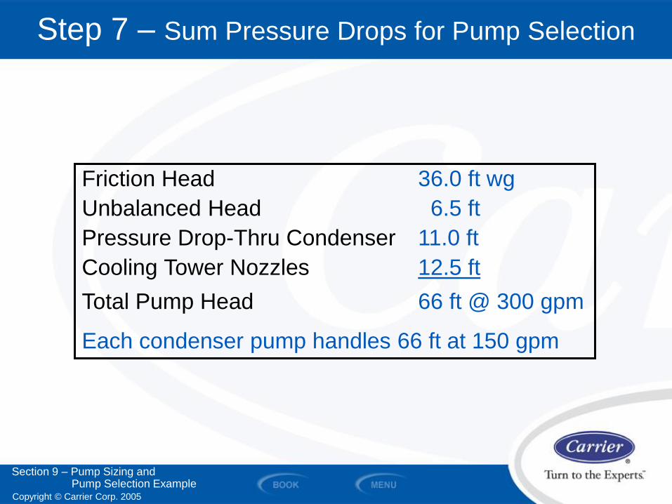
Step 7 – Sum Pressure Drops for Pump Selection
Friction Head 36.0 ft wg
Unbalanced Head 6.5 ft
Pressure Drop-Thru Condenser 11.0 ft
Cooling Tower Nozzles 12.5 ft
Total Pump Head 66 ft @ 300 gpm
Each condenser pump handles 66 ft at 150 gpm
Section 9 – Pump Sizing and Pump Selection Example
Copyright © Carrier Corp. 2005
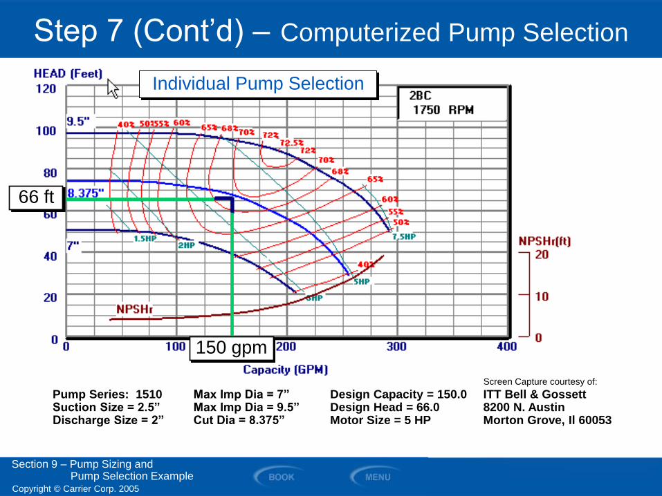
Step 7 (Cont’d) – Computerized Pump Selection
Pump Series: 1510 Max Imp Dia = 7” Design Capacity = 150.0 ITT Bell & Gossett Suction Size = 2.5” Max Imp Dia = 9.5” Design Head = 66.0 8200 N. Austin Discharge Size = 2” Cut Dia = 8.375” Motor Size = 5 HP Morton Grove, Il 60053
Section 9 – Pump Sizing and Pump Selection Example
Individual Pump Selection
66 ft
150 gpm
Screen Capture courtesy of:
Copyright © Carrier Corp. 2005
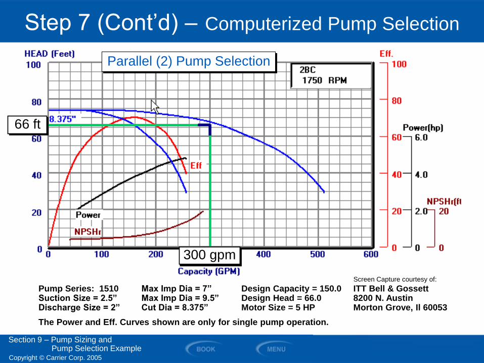
Step 7 (Cont’d) – Computerized Pump Selection
Pump Series: 1510 Max Imp Dia = 7” Design Capacity = 150.0 ITT Bell & Gossett Suction Size = 2.5” Max Imp Dia = 9.5” Design Head = 66.0 8200 N. Austin Discharge Size = 2” Cut Dia = 8.375” Motor Size = 5 HP Morton Grove, Il 60053
The Power and Eff. Curves shown are only for single pump operation. Section 9 – Pump Sizing and Pump Selection Example
Parallel (2) Pump Selection
66 ft
300 gpm
Screen Capture courtesy of:
Copyright © Carrier Corp. 2005
Section 9 – Pump Sizing and Pump Selection Example
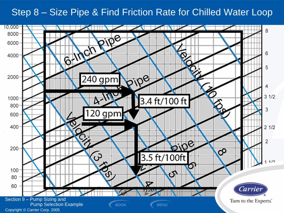
Step 8 – Size Pipe & Find Friction Rate for Chilled Water Loop
Copyright © Carrier Corp. 2005
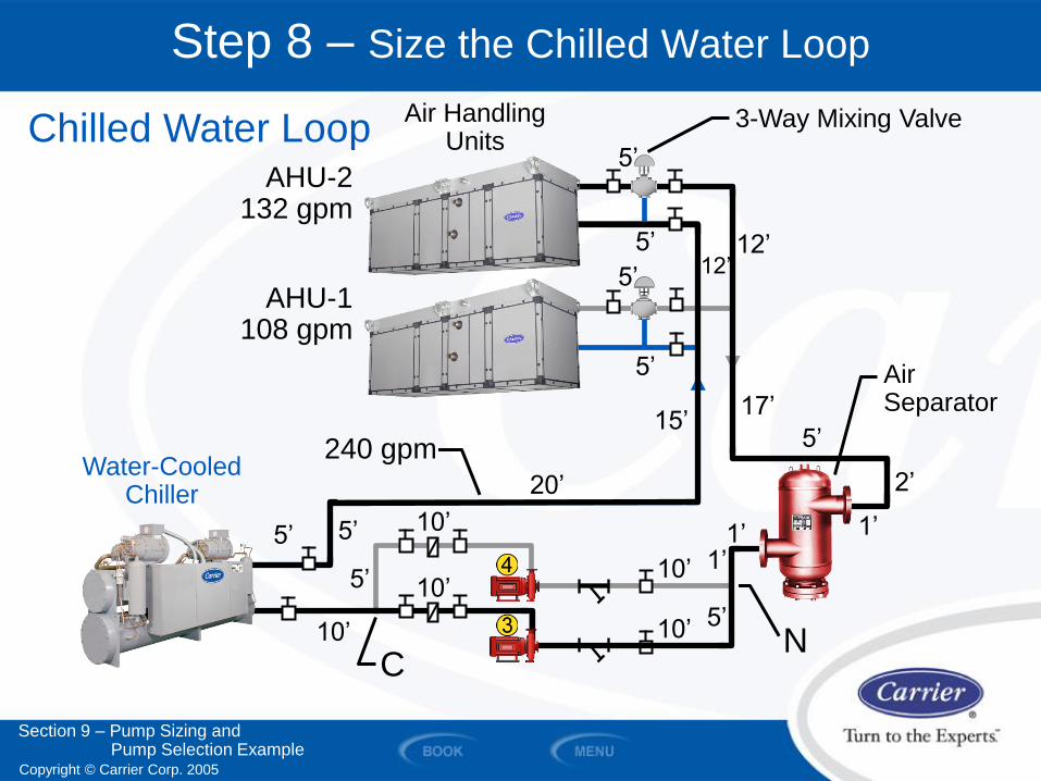
Step 8 – Size the Chilled Water Loop
Air Handling Units
3-Way Mixing Valve
10’
10’
10’
5’ 5’
5’
C
10’
10’ 5’
1’ 1’
20’
15’ 17’
5’
2’
1’
5’
5’
5’
5’ 12’
12’
Air Separator
Water-Cooled Chiller
Chilled Water Loop
N
AHU-2 132 gpm
AHU-1 108 gpm
240 gpm
Section 9 – Pump Sizing and Pump Selection Example
Copyright © Carrier Corp. 2005
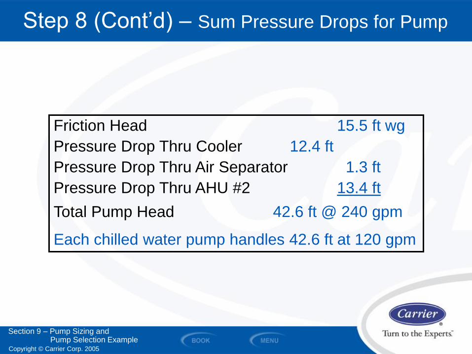
Step 8 (Cont’d) – Sum Pressure Drops for Pump
Friction Head 15.5 ft wg
Pressure Drop Thru Cooler 12.4 ft
Pressure Drop Thru Air Separator 1.3 ft
Pressure Drop Thru AHU #2 13.4 ft
Total Pump Head 42.6 ft @ 240 gpm
Each chilled water pump handles 42.6 ft at 120 gpm
Section 9 – Pump Sizing and Pump Selection Example
Copyright © Carrier Corp. 2005
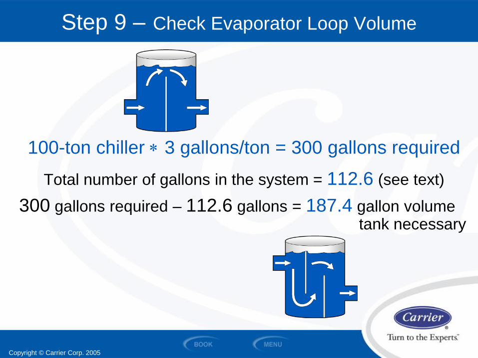
Step 9 – Check Evaporator Loop Volume
100-ton chiller 3 gallons/ton = 300 gallons required
Total number of gallons in the system = 112.6 (see text)
300 gallons required – 112.6 gallons = 187.4 gallon volume tank necessary
Copyright © Carrier Corp. 2005
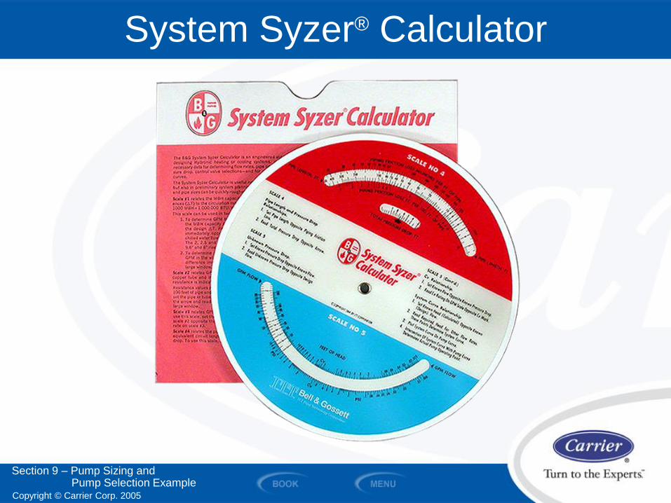
System Syzer® Calculator
Section 9 – Pump Sizing and Pump Selection Example
Copyright © Carrier Corp. 2005
SECTION 10
Summary
WATER PIPING AND PUMPS
Copyright © Carrier Corp. 2005
Summary
• Compared the 3 types of piping systems
• Identified the 4 types of water distribution systems
• Differentiated between direct return and reverse return systems
• Identified the various valves and hydronic accessories available for use in piping systems
• Diagrammed typical piping hookups for chillers, pumps, and cooling towers
• Sized the piping for a closed and an open-loop system
• Identified the types of water pumps, their features, and the selection process
Section 10 – Summary
Copyright © Carrier Corp. 2005
Work Session
Work Session
WATER PIPING AND PUMPS
Work Session
1. A chilled water system is a _________________ loop system.
2. A condenser water system with a cooling tower is a ___________________ loop system.
3. What are the 4 types of valves that can be used for balancing/throttling?
1. ___________________________________________
2. ___________________________________________
3. ________________________ ____
Copyright © Carrier Corp. 2005
Technical Development Program
Thank You This completes the presentation.
TDP 502 Water Piping and Pumps
Artwork from Symbol Library used by permission of
Software Toolbox www.softwaretoolbox.com/symbols