Embed Size (px)
DESCRIPTION
Handbook
Citation preview

7/18/2019 Pumping Handbook
http://slidepdf.com/reader/full/pumping-handbook 1/80
PSS Handbook

7/18/2019 Pumping Handbook
http://slidepdf.com/reader/full/pumping-handbook 2/80

7/18/2019 Pumping Handbook
http://slidepdf.com/reader/full/pumping-handbook 3/80
PSS Handbook

7/18/2019 Pumping Handbook
http://slidepdf.com/reader/full/pumping-handbook 4/80
IV
PSS Handbook This PSS handbok is published by ITT Water & Wastewater AB,
the producers of Flygt pumps.
ITT is a global provider of water handling and treatment solutions for
municipal and industrial customers in more than 140 countries. Thecompany designs and delivers energy-efficient solutions and related
services for water and wastewater transport, biological
treatment, filtration, and disinfection through five global brands –Flygt, Godwin Pumps, Leopold, Sanitaire and Wedeco.
Copyright © 2010 ITT Water & Wastewater AB. All rights reserved.
Printed in Sweden
Published by ITT Water & Wastewater AB,
Gesällvägen 33, SE-174 87 Sundbyberg, Sweden
Executive Editor
Tore Strandberg
Co-Editors
Per HedmarkHenrik Held
Anders Ström

7/18/2019 Pumping Handbook
http://slidepdf.com/reader/full/pumping-handbook 5/80
V

7/18/2019 Pumping Handbook
http://slidepdf.com/reader/full/pumping-handbook 6/80
VI Contents
Chapter 1Introduction 4-51.1 Why PSS? 4
Chapter 2Pressure sewage systems 6-7 2.1 Residential housing, commercial and municipal applications 6
Chapter 3Other wastewater transport system descriptions 8-113.1 Septic tanks 83.2 Septic Tank Effluent Pump Pressure Sewers (STEP) 83.3 Small wastewater treatment plants 93.4 Gravity sewer 103.5 Vacuum sewer system 11
Chapter 4 System sizing 12-394.1 Pump selection 124.1.2 Hydraulic characteristics for both progressive cavity grinder pumps and centrifugal grinder pumps when utilized in PSS applications 154.1.3 Progressive cavity grinder pumps in PSS systems 164.1.4 Centrifugal grinder pumps in PSS systems 194.1.5 What are the hydraulic design system requirements that must be fulfilled? 224.1.6 Designing pressure sewage systems with multiple grinder pumps running simultaneously 23
4.1.7 Statistical method 244.1.8 Rational Method for establishing design flows in PSS 264.1.9 Peak Flow method 274.1.10 Probability theory 274.2 Distribution network installation tips 294.2.1 Profile recommendations 294.2.2 Pipe installation tips 304.2.3 Pipe dimensions and pressure class definition 314.3 Control and Supervision strategies 324.3.1 PSS Monitoring & Control solutions 324.4 Basin design 364.5 Air-release valves, Siphon breakers 39
Chapter 5Design tools 40-43
Chapter 6Description of hydraulic end types 44-47 6.1 Centrifugal grinder pumps 446.1.2 Comparison of multi-vane and recessed / vortex impellers 466.2 Progressive cavity grinder pumps 46
Chapter 7Hydrogen sulfide in PSS 48-53
Contents

7/18/2019 Pumping Handbook
http://slidepdf.com/reader/full/pumping-handbook 7/80
VIIContents
Chapter 8 Appendixes 54-718.1 Electrical pump parameters 558.1.1 Background 558.1.2 Power ratings at different duty conditions 588.1.3 The essential parameters 588.1.4 Conclusions 588.2 Flygt PSS assortment 598.3 Pump and pipe design guideline 608.4 Checklist for a PSS design 628.5 Abbreviation descriptions and List of Symbols 648.6 References 70

7/18/2019 Pumping Handbook
http://slidepdf.com/reader/full/pumping-handbook 8/80

7/18/2019 Pumping Handbook
http://slidepdf.com/reader/full/pumping-handbook 9/80
1
Disclaimer
All information in this handbook has been published in good faith and all reasonable care has been taken to ensurethe accuracy of its content. Nevertheless, this handbook is presented with the understanding that the authors and
publishers are not responsible for errors or omissions and make no warranty, express or implied, with respect to the
currency, completeness or accuracy of its contents. The authors and publishers do not assume liability, including direct,
indirect, incidental or consequential losses or damages, resulting from the use or application of any of the data or
information contained herein. This work is published with the understanding that the author and publishers aresupplying information but are not attempting to render engineering or other professional services. If such services are
required, the assistance of an appropriate professional should be sought.
Acknowledgements
This handbook would not have been accomplished without the global team spirit in ourcompany. We would especially like to thank the following people for valuable input andcontribution: John Bauer, Ad Damme, Klas Dans, Doug Darville, Alain Derville, Per Hedmark,Björn Lundqvist, Dana Mullen, Therese Myske, Erik Quijano, Johan Seijmer, Anders Ström,Roland Svensson and Peter Söderlund.

7/18/2019 Pumping Handbook
http://slidepdf.com/reader/full/pumping-handbook 10/80
2

7/18/2019 Pumping Handbook
http://slidepdf.com/reader/full/pumping-handbook 11/80
3
Foreword
Flygt pumps have been installed in wastewater applications for more than 50 years.
Following the worldwide boom in demand for reliable pressure sewage systems with long life,we realized the need for guidelines to design such systems.
This handbook is intended to give practical recommendations to wastewater consultants in theirPSS system design work. It also aims to provide a basic understanding of the PSS application forusers and operators as well as tips to contractors who work on such installations.
A PSS system consists of a branched network including liquid pressure generating equipment(pumps).
The target scope is mainly directed to the Australian, European and American markets. That iswhy some parts of the handbook might be outside the most common praxis in some markets.But that uncommon praxis might also provide you with some new ideas.
Complementary documentation can be installation and operation manuals, pump handbookcovering more advanced duty point estimation, guidelines for electrical machine installation andpipe foundation recommendation handbooks.
The first chapters are devoted to introducing readers to PSS. The latter ones explain our designguidelines and look at deeper issues, such as the formation of hydrogen sulphide. This handbook was produced with assistance from people within our organization from aroundthe world with many years of PSS experience.
The Flygt product organization is present worldwide to provide our customers with personalsupport. Don’t hesitate to contact us if you need any additional information.

7/18/2019 Pumping Handbook
http://slidepdf.com/reader/full/pumping-handbook 12/80
4 Chapter 1 – Introduction
1.1 Why PSS?
Initially developed in the United States in the 1960s, pressurized sewage systems (PSS) becamepopular in the early 1970s in rural areas where high water tables and rocky ground made theuse of conventional sewer systems difficult and costly. The worldwide breakthrough for pressuresystems occurred around 1980 with the development of sub-mersible centrifugal pumps withgrinders. These pumps were inexpensive, reliable and easy to use. They could also pump rawsewage at high pressures through systems using small-diameter pipes. Due to the high costs ofgravity sewage systems, pressure sewers have become one of the most popular and practicalforms of alternative collection systems today, especially in less densely populated areas.
There are several options for handling wastewater, including transportation by gravitysewers, local wastewater treatment plants, septic tanks and PSS systems. PSS hasadvantages over other systems, including:• Cost-efficient installation, particularly in hilly and rocky areas and when dealing
with high water tables, very flat land and stream crossings• Reliability with no need for time-consuming and/or costly operation or
maintenance.
Flygt has supplied pumps for pressure sewage markets around the world since the1980s. Those sales include:• 150,000 grinder pumps installed in Holland• 40,000 grinder pumps installed in Germany• 27,000 pumps in prefabricated Compit stations• 10,000 PSS-systems in operation• PC grinder pumps in Australia, the U.S. and Scandinavia
Flygt participated in and drove development of European PSS standard EN 1671 (standards used
in the U.S. are UL, CSA and/or NSF).
Chapter 1
The purpose of this handbook is to provide consultants, designers, contractors, city planners and
system PSS operators with information and guidelines for sizing and designing pressure sewage
systems PSS. Advice is also offered for the selection of proper PSS packages, including pumps,
basins, monitoring and control equipment and accessories such as valves and siphon breakers.
Pipe and pump selection are also covered in the brochure, and descriptions of Flygt software tools
are also provided. We are present in the PSS markets in Australia, Europe and North America, so
this book may therefore include discussions that are not applicable to every market; however, the
contents include useful design tips.
Introduction

7/18/2019 Pumping Handbook
http://slidepdf.com/reader/full/pumping-handbook 13/80
5Chapter 1 – Introduction
In addition to the most reliable high-quality PSS pumps, we also offer:• System design services that use the most modern and sophisticated software tools• An extensive range of pumps and monitoring and control equipment• Local installation and after-sale service• A worldwide network of staff and production facilities.
The Flygt line includes progressive cavity designs and centrifugal grinder pumps that reach headsup to 220 ft (67 m) and 95 USGPM (6 l/s) .
New legislation that raises treatment standards and requirements to protect local recipients hasincreased the need for new installations of wastewater equipment.
Pressure sewage systems are frequently used in less densely populated areas such as suburbsand rural areas. This handbook presents the Flygt perspective on designing such systems. Itexplains system requirements, shows how to determine the required performance of components
such as pump duty points and covers the differences between using centrifugal grinders andprogressive cavity pumps. As pressure sewage systems typically use long pipes, preventinghydrogen sulfide odor and corrosion is important (see chapter 7). Hydraulics such as minimumwater velocity, retention time, and valve locations are also discussed.
For recommendations on operation, installation and maintenance, see the Installation, Operation
and Maintenance Manual for pumps.
The purpose of wastewater treatment is to separate sludge from water and make it possible forwater to be returned to the recipient for reuse. For households this can be done using either amicro-wastewater treatment plant (household size) on the property or by transporting waste-water to a treatment plant; these functions are described in the next chapter. Local wastewatertreatment plants can be efficient solutions in remote and less densely populated areas.
Wastewater can be transported to a larger wastewater treatment plant with a gravity pipe system
or a pressurized sewage system. The gravity system, most commonly used in cities and suburbs,relies on a minimum inclination of the sewer pipe to the pump station. Septic tank systems arefrequently used in more rural, remote locations. Their functionalities are described in chapter 3.2.

7/18/2019 Pumping Handbook
http://slidepdf.com/reader/full/pumping-handbook 14/80
6 Chapter 2 – Pressure sewage systems
Pressure sewage systems
A pressure sewage system consists of a branched, small-diameter pipe system. The systemis based on small pump stations located near homes from which wastewater is received. A smallsystem may involve only a few households, while a large system can include as many as severalhundred pump stations. Sometimes several households connect to a single pump station.
The usual pump basin volume is 100-130 US Gallon or 400-500 litres which often equals areceiving capacity of 24 hours. Pumps are usually grinder types that reduce solids in the waste-water to small particles that help prevent clogging of the pump and pipe system. A typicalpump size is in the range of 1.3 kW, 1.3-4 HP and maximum flow 16-48 USGPM, 1-3 l/s.
Wastewater from a PSS system is released into the main sewer or into a larger receiving pumpstation for subsequent transportation to a wastewater treatment plant. A typical householdproduces between 100-200 GPD per day of wastewater or 400-800 litres.
Wastewater transport can be divided into residential, commercial and municipal applications.
Chapter 2
Figure 2.1
Landscape showing PSS basins and pressure piping.

7/18/2019 Pumping Handbook
http://slidepdf.com/reader/full/pumping-handbook 15/80
7Chapter 2 – Pressure sewage systems
2.1 Residential housing, commercial and municipal applications Though the purpose and method of wastewater handling is the same, there are differencesin the application of residential, commercial and municipal PSS systems. For the purpose ofclarification, those differences are listed below. Please note that this handbook only focuseson systems with residential applications. If needed, Flygt can also provide guidelines and
recommendations for commercial wastewater transport applications.
Residential applications often have:• Small pumps that typically weigh less than 50 kg, 100 lbs, 5 kW, 7 HP (please see
appendix 8.1 for more information on power rating) and 2 l/s, 30 USGPM• Higher focus on maintenance-free equipment• Less focus on energy efficiency• Limited power supply
Commercial applications usually have:• The pump station located inside the building or on the lot of the facility• Higher flows•
Larger pumps• Longer running hours• Higher demands on redundancy as consequences of a system failure are more
serious• Wastewater with sometimes higher solids content, paper towels, grease, etc.• Sometimes high fluctuations in flow• Professional maintenance by “generalist” operators who monitor, control and
operate using industrial equipment (i.e. remote supervision).
Municipal applications:• Have lift stations on the wastewater distribution net•
Can have large pumps• Can be telemetric monitored (from the wastewater treatment plant down-stream)• Are operated by professional operators trained for wastewater pump applications
Figure 2.2
Elevation view of a PSS tank and typical included com-
ponents. Either centrifugal grinder pumps or progressive
cavity grinder pumps are used. Different pump station
configurations are used for different markets. Two levelswitches are used in Scandinavia, for example, while
three are used in the U.S. To close the shut-off valve a
pro-longed handle is usually used.

7/18/2019 Pumping Handbook
http://slidepdf.com/reader/full/pumping-handbook 16/80
8 Chapter 3 – Other wastewater transport system descriptions
Other wastewater transportsystem descriptionsIn wastewater transport, water is used to transport human waste for treatment. The purposeof wastewater treatment is to separate water and sludge so that clean water can be released toa recipient. Several methods can be used such as treating wastewater locally and occasionallytransporting sludge away by truck. Another method is to pump wastewater into a large-scalewastewater treatment plant. The following is a general description of those systems, includingseptic tanks, small wastewater treatment plants, wastewater gravity systems and vacuum sewersystems.
3.1 Septic tanks
A septic tank is a sealed underground tank into which sewage from a household enters. Theheavier solids in wastewater settle in the septic tank. Self-forming bacteria in the tank help thesystem to ‘digest’ these solids or sludge. At certain intervals the remaining solids are emptiedand transported away by a septic tank pump hauler.
Instead of pumping the separated liquid away from the property, an infiltration system can alsobe used to follow the septic tank. This requires a well functioning system to avoid local dischargeof untreated wastewater. Baffles built into the tank hold back the floating scum and prevent itfrom moving past the outlet of the tank.
3.2 Septic Tank Effluent Pump Pressure Sewers (STEP)
A STEP system pumps effluent in a branched system the same way that pressure sewage systemswith grinder pumps do. The main difference is that in the STEP system an interceptor tankfor removing solids and grease is included, reducing the amount of solids in the effluent thatneed to be pumped to the wastewater treatment plant. The STEP also features a pumping
chamber with a pump that is equipped with a recessed or ½” solid handling throughlet (a Flygtpump impeller type M, D, N or C), check valves, shut-off valves, and a monitoring and controlsystem. The sewage separated in the interceptor tank must be emptied on a regular basis andtransported to the treatment plant.
Chapter 3

7/18/2019 Pumping Handbook
http://slidepdf.com/reader/full/pumping-handbook 17/80
9Chapter 3 – Other wastewater transport system descriptions
Figur 3.1
Typical STEP system on lot facilities. The separated liquid enters a pump sump by an overflow weir from where it ispumped to the nearby wastewater pipe system. The solids settle in the septic tank and the liquid is pumped away
for treatment. Several households can use the same pump.
Figure 3.2
Wastewater treatment plant for typically 1-5 PE.
3.3 Small wastewater treatment plants
The treatment process in small wastewater plants is basically the same as in large ones (but with-out pre-treatment, grit chamber etc.), in that it has both a biological step in which nitrogen isremoved and a chemical step in which solids assemble and settle, allowing for the separationof settled sludge and water. The treated water is then released for infiltration to the ground orto a local recipient such as a lake. The treatment can also include disinfection before the wateris discharged. The sludge is then emptied and stored in local compost facilities or emptied andtransported away by truck once or twice a year. The number of households connected to thesystem is usually between one and five. Power consumption needed for treatment is also low.
Other costs for treatment of the wastewater include chemicals and sludge transportation.
Treatment is measured by the reduction of biological oxygen demand (BOD) and chemical oxygen
demand (COD). The degree of treatment obtained can typically be: BOD5-reduction >90%,COD-reduction >90%, P total reduction >90%.

7/18/2019 Pumping Handbook
http://slidepdf.com/reader/full/pumping-handbook 18/80
10 Chapter 3 – Other wastewater transport system descriptions
Gravity sewers are sloping pipes that convey wastewater from individual households or
multiple household buildings to pumping stations and waste-water treatment plants. Sewerbranches connect to the main branch. Since the pipe must have a slope to make the water flow with
sufficient speed to avoid sedimentation of the solids in the pipe, lift pump stations have tobe used when the pipe reaches a certain depth. A self-cleansing velocity of the sewage in thepipe generally requires a minimum flow rate of 0.7 m/s, 2 ft/s. Sewers are laid beneath roads atcertain depths to avoid damage from overhead traffic loads. Typical slopes are approximately 1%.
Gravity sewers can carry both sewage and rainwater (combined sewers) or have separate pipesfor sewage and stormwater.
Gravity sewers are economically beneficial in densely populated areas where large flows mustbe transported. Because they require less mechanization, gravity sewer wastewater systems alsoresult in maintenance savings.
This technology also provides a high level of hygiene and comfort for households and requiresno maintenance by homeowners (since the municipality maintains the equipment).
Figure 3.3
The sewage from the households is discharged to the sewer main which has a slope making the liquid flowing to the
receiving pump station
3.4 Gravity sewer

7/18/2019 Pumping Handbook
http://slidepdf.com/reader/full/pumping-handbook 19/80
11Chapter 3 – Other wastewater transport system descriptions
3.5 Vacuum sewer system
In a vacuum sewer system, vacuum is created using a pump that sucks sewage from a buffertank in a household, households or lot into a larger central tank where the pump is located.To have a cost efficient system only a few meters under pressure (vaccum) is possible and the sizeof such systems are limited, especially in hilly areas.
The vacuum system consists of• Buffer tank with level control and a motor-controlled valve• Vacuum sewer• Pump station with vacuum pump and sewage pump.
The wastewater from the household enters the buffer tank through a gravity pipe. When theliquid reaches a certain level the valve opens and sewage is sucked into the sewer. Before the valve
opens, it ensures that no other unit is in its emptying phase. The sewer has a declining angle ofapproximately 0.3%. After a certain distance the sewer has a steep in-clination of a few meters,a transport pocket, then declines again until it reaches the pump station (i.e., the sewer is laidin a saw-tooth profile with 50 – 70 meters between the lifts). The liquid accumulates in thepockets and is lifted in intervals when the vacuum valve opens. The liquid then flows to the nextlow-level point of the pipe and lifts when the vacuum valve opens the next time.
The reliability of the system is very dependant on the maintenance efforts.
Figure 3.4
As soon as the buffer tank is filled a valve opens and the buffer tank is emptied by the low pressure.

7/18/2019 Pumping Handbook
http://slidepdf.com/reader/full/pumping-handbook 20/80
12 Chapter 4 – System sizing
System sizing
In the design process of a pressure sewage system, pumps and pipes are selected to ensurethat the system will work without failures or unwanted stops. The following chapter is dividedaccording to the components included in a PSS package: the pump, tank/basin/sump includingvalves and piping, and monitoring and control equipment. As pipe selection is closely connectedto pump size selection, the latter is discussed here as well.
The primary customer requirement is a PSS system that operates without the need for manual work
(such as for sedimentation in the pipes, blocked pumps, etc.). The energy consumption is usuallyof less importance. (Energy-efficient pumping can be defined by using specific energy; pleasesee the appendix for definitions).
4.1 Pump selection
This chapter describes different pumping duties in a PSS with grinder centrifugal pumps orprogressive cavity grinder pumps. The system curve defines, together with the Q-h curve, the duty point for the pump. Because ofthe long pipes in PSS, the system curve is often steep; i.e., the major portion of the total headloss is from pipe friction.
Chapter 4
Figure 4.1.1
System curve with a small static
head and high dynamic head from
the friction losses in a long pipe,
htot = hgeo + hdynamic.
Pump curve
Duty point
Head
Q
Flow H
Statichead
System curve
7/18/2019 Pumping Handbook
http://slidepdf.com/reader/full/pumping-handbook 21/80
13Chapter 4 – System sizing
Static head
The static head is usually defined as the elevation difference between the water surface abovethe pump and the liquid surface at the outlet, or the elevation of the outlet if it is above the
surface. For a pipe design as pictured, the second part of the pipe will empty itself after the pumphas stopped. Air will entrain from the outlet and the right water column and be separated fromthe left water column at the pipes’ peaks.
Figure 4.1.2
The outlet of the liquid is above
the surface. As a result, the rightpart of the pipe will be emptied
after the pump stops.
When the static head and duty point for the pump are estimated, the peaks of the pipe mustbe considered.
Friction head loss
The dynamic head loss is estimated according to:
Where hdynamic is the head loss in m or ft, ƒ friction factor, l pipe length, d pipe diameter, v water
velocity in the corresponding pipe section with diameter .
To define the pumps’ duty points {GPM, l/s}, liquid velocities{FPS, m/s} and junction node results{PSI, ft/m}, We use hydraulic modeling software such as RioGl and KYPipe to size pipes and runvarious hydraulic simulations for both residential and commercial applications.
When designing a system, the following parameters are needed as inputin the design process:• Vacation homes or permanent residences• Number of households {equivalent dwelling units (EDUs)}• Number of pumps running in simultaneous operation based on
Rational method or Probability method design criteria• Volume of wastewater as defined as design flow• Future extension/expansion of the PSS system• Topology {static elevation}• Area development sequence and build-out schedule• Need for extra-high reliability (duplex pump stations)•
Monitoring, control and maintenance strategies• Pipe type• Power available

7/18/2019 Pumping Handbook
http://slidepdf.com/reader/full/pumping-handbook 22/80
14 Chapter 4 – System sizing
The result from the estimation will be the pumps’ running conditions (i.e., duty points at different
numbers of pumps running simultaneously, water velocities and head pressure in the differentpipes’ retention time).
The designer fine-tunes and checks different combinations of pipe dimensions, number of
different pumps running, etc., until the optimal system is found.
The differences in system hydraulics for the centrifugal and PC grinder are discussed below.
Figure 4.1.3
Screenshot from a design software
showing a PSS map for a system of
households in which the white dots
represent each PSS tank/basin/sump.The straight lines are the piping. The
outlet of the system is shown at left.
Figure 4.1.4
PSS design example with KY
Pipe 2000

7/18/2019 Pumping Handbook
http://slidepdf.com/reader/full/pumping-handbook 23/80
15Chapter 4 – System sizing
Figure 4.1.5
Output result from software RioGl. The table includes estimations of the different pumps’ duty points(i.e., the intersection between the pump curve and the system curve).
4.1.2 Hydraulic characteristics for both progressive cavity grinderpumps and centrifugal grinder pumps when utilized inPSS applications
The progressive cavity grinder pump produces a relatively constant flow at various dischargepressures and produces limited flow between 9–15 GPM/0.7–1.1 l/s. The centrifugal grinder
pump will produce various flows based on the system head conditions of between 20–25GPM/1.5–1.9 l/s.
Both hydraulic design characteristics are currently used in pressure sewer systems. Topography,design flow and pipe type and size will help to determine the best hydraulic choice.
Progress cavity grinder pump• The pump has a steep performance curve, hence a low power uptake
at high heads (but with a low flow).• It is most beneficial in hilly country (high peaks and static heads).
Figure 4.1.6
Pipe data and estimated water velocities in the different pipes.
Pump-name
Pump type Capa- city[l/s]
Head losses [m] RunningTime[min/day]
Liquid level pump operati.
Total[m]
Friction[m]
Static[m]
DynNod[m]
Start[m]
Stop[m]
P0016/p1 MP 3068-210-2.4 kW-3 Ph 2.7 25.3 24.7 0.1 0.5 4 -0.10 -0.20
P0023/p1 MP 3068-210-2.4 kW-3 Ph 1.7 29.5 28.6 0.1 0.7 6 -0.10 -0.20
P0014/p1 MP 3068-210-2.4 kW-3 Ph 1.6 29.9 29.0 0.1 0.8 7 -0.10 -0.20
P0004/p1 MP 3068-210-2.4 kW-3 Ph 2.3 27.2 26.4 0.1 0.6 5 -0.10 -0.20
P0007/p1 MP 3068-210-2.4 kW-3 Ph 2.1 28.0 27.0 0.1 0.8 5 -0.10 -0.20
P0008/p1 MP 3068-210-2.4 kW-3 Ph 2.1 28.1 27.1 0.1 0.9 5 -0.10 -0.20
Results for each pump
Start End Length
[m]
Diam.Internal[mm]
M aterial Friction-Coeffi- cient
Frict ion head losses[m]
M ax.Velocity[m/s]
M ax.Flow[l/s]Pipes Nodes
T0001 L0001 18.10 44.3 PE SDR 17 0.15 4.53 0.00 2.77 4.27
T0017 P0016 34.10 35.5 PE SDR 17 0.15 11.32 0.16 2.76 2.73
T0025 P0023 33.71 35.5 PE SDR 17 0.15 4.60 0.06 1.75 1.73
T0004 0001 25.48 35.5 PE SDR 17 0.15 6.10 0.11 2.33 2.31
0003 P0014 14.49 35.5 PE SDR 17 0.15 1.71 0.04 1.62 1.60
0001 0002 20.52 35.5 PE SDR 17 0.15 4.91 0.08 2.33 2.31
T0006 P0004 12.36 35.5 PE SDR 17 0.15 2.89 0.11 2.31 2.28
T0009 P0007 11.92 35.5 PE SDR 17 0.15 2.36 0.09 2.12 2.09
T0009 T0010 5.11 35.5 PE SDR 17 0.15 0.98 0.09 2.09 2.06
T0010 P0008 11.11 35.5 PE SDR 17 0.15 2.14 0.09 2.09 2.06
T0013 P0011 12.62 35.5 PE SDR 17 0.15 1.95 0.07 1.87 1.84
T0013 T0014 7.37 35.5 PE SDR 17 0.15 1.10 0.07 1.83 1.81
T0014 P0012 12.59 35.5 PE SDR 17 0.15 1.88 0.07 1.83 1.81
T0014 T0015 42.88 35.5 PE SDR 17 0.15 5.34 0.06 1.67 1.65
T0028 P0026 32.18 35.5 PE SDR 17 0.15 3.85 0.05 1.63 1.61
T0024 0006 16.45 35.5 PE SDR 17 0.15 2.41 0.07 1.81 1.79
Results for each pipe
7/18/2019 Pumping Handbook
http://slidepdf.com/reader/full/pumping-handbook 24/80
16 Chapter 4 – System sizing
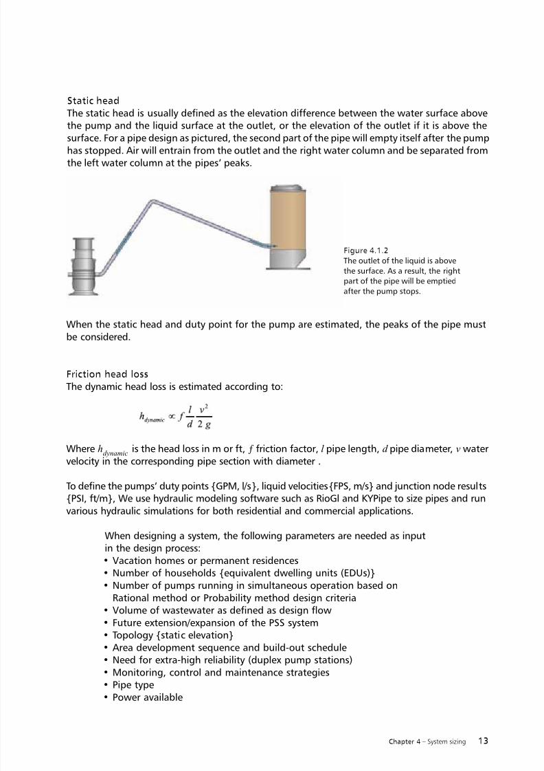
Figure 4.1.7
A positive displacement pump causes a fluid to move by
trapping a fixed amount and then forcing (displacing)that trapped volume into the discharge pipe.
• Progressive cavity pumps are widely used for pumping difficult materials,
such as sewage sludge.• A pump consists of a helical-shaped rotor that fits inside a rubber sleeve called
the stator. As the rotor rotates, fluid is gradually forced up the rubber sleeve.• Its performance curve is almost vertical.• The typical rated power is 1.7 HP, 1.3 Kw.
The usable pump curve for a PC (grinder) pump is almost vertical (i.e., the flow is almostconstant at all duty points). Typical maximum pump head is 200 ft or 60 m. However, whensizing a pressure sewer system, normal duty points should not exceed 160 total head ft/50 m.
Centrifugal grinder pump• The pump is wear-resistant.• The high-pumped flow scours the pipes and empties the tank fast (i.e., due to
the short running time, less numbers of pumps will run simultaneously in largesystems, and the risk of pipe clogs is reduced).
• Larger pumps – and larger motors – are needed at very high static heads.
A PSS system can contain a large number of pumps, so it can be advantageous to have aminimum number of different pumps for maintenance purposes (of large PSS systems).
4.1.3 Progressive cavity grinder pumps in PSS systems
7/18/2019 Pumping Handbook
http://slidepdf.com/reader/full/pumping-handbook 25/80
17Chapter 4 – System sizing
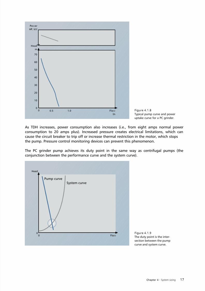
Figure 4.1.9
The duty point is the inter-section between the pump
curve and system curve.
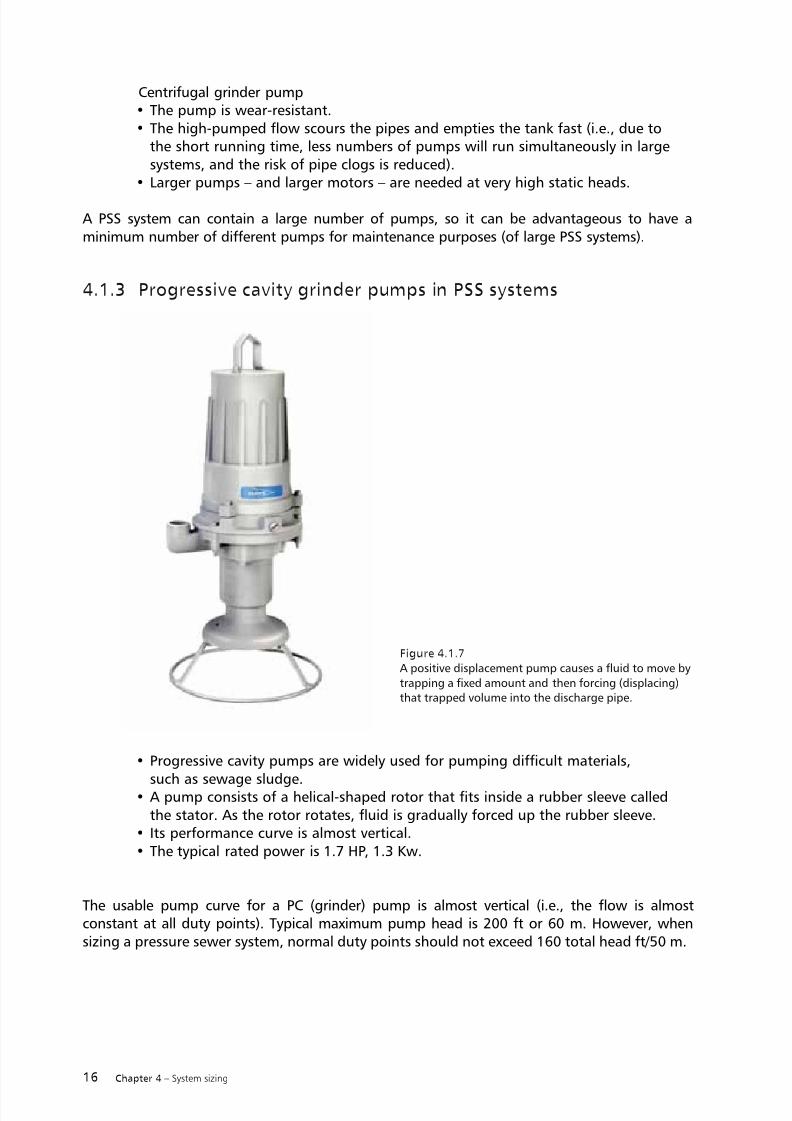
As TDH increases, power consumption also increases (i.e., from eight amps normal powerconsumption to 20 amps plus). Increased pressure creates electrical limitations, which cancause the circuit breaker to trip off or increase thermal restriction in the motor, which stopsthe pump. Pressure control monitoring devices can prevent this phenomenon.
The PC grinder pump achieves its duty point in the same way as centrifugal pumps (the
conjunction between the performance curve and the system curve).
Figure 4.1.8
Typical pump curve and poweruptake curve for a PC grinder.
Pump curveSystem curve
0
10
50
40
30
20
70
60
0 0.5 1.0
Power
HP, kW
Flow
l/s
Head
Flow0
0
Head
m

7/18/2019 Pumping Handbook
http://slidepdf.com/reader/full/pumping-handbook 26/80
18 Chapter 4 – System sizing
In a large system several pumps run simultaneously. Multiple pumps have different duty pointscompared with a single pump running in the system.
Figure 4.1.10
Top view of a PSS system from RioGl. For example, two
pumps in a large system can be running simultaneously,depending on the water consumption in the household
and the number of pumps.
Figure 4.1.11
When an additional grinder pump
in the system starts to empty itstank/basin/sump, the pressure in
the common force main increases,resulting in a slightly higher duty
point for the pump.
Performance
Pump curve
System curve
Head
feet, m
FlowGPM, l/s
Static
head
Duty point for two
pumps running
Duty point for one
pump running
7/18/2019 Pumping Handbook
http://slidepdf.com/reader/full/pumping-handbook 27/80
19Chapter 4 – System sizing
A detailed calculation is required to ensure, for example, that sufficient scouring velocities inthe pipe are obtained (see chart above). It is also important that the maximum pressure in thesystem is estimated to ensure that equipment does not break.
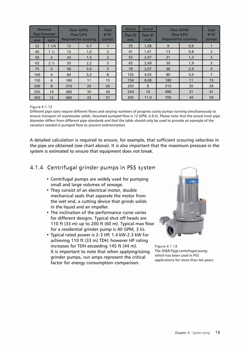
4.1.4 Centrifugal grinder pumps in PSS systems
• Centrifugal pumps are widely used for pumpingsmall and large volumes of sewage.
• They consist of an electrical motor, doublemechanical seals that separate the motor fromthe wet end, a cutting device that grinds solidsin the liquid and an impeller.
• The inclination of the performance curve variesfor different designs. Typical shut off heads are110 ft (33 m) up to 200 ft (60 m). Typical max flowfor a residential grinder pump is 40 GPM, 3 l/s.
• Typical rated power is 2-3 HP, 1.4 kW-2.3 kW for
achieving 110 ft (33 m) TDH; however HP ratingincreases for TDH exceeding 145 ft (44 m).It is important to note that when applying/sizinggrinder pumps, run amps represent the criticalfactor for energy consumption comparison.
Figure 4.1.12
Different pipe sizes require different flows and varying numbers of progress cavity pumps running simultaneously to
ensure transport of wastewater solids. Assumed pumped flow is 12 GPM, 0.8 l/s. Please note that the actual inner pipe
diameter differs from different pipe standards and that the table should only be used to provide an example of thevariation needed in pumped flow to prevent sedimentation.
Figure 4.1.13
The 3068 Flygt centrifugal pump,
which has been used in PSS
applications for more than ten years.
Nominal
Pipe DiameterFlow (GPM)
Flow (LPS)
Required for scouring
Total
# PC
pumpsmm inch
32 1 1/4 12 0,7 1
40 1 ½ 15 1,0 2
50 2 24 1,5 2
63 2 ½ 35 2,2 3
75 3 58 3,6 5
100 4 84 5,3 8
150 6 180 11 15
200 8 310 20 26
250 10 480 30 40
300 12 680 43 57
Actual Actual Flow (GPM)
Flow (LPS)Required for scouring
Total
# PCpumps
Pipe ID
mm
Pipe ID
inch
35 1,38 9 0,6 1
41 1,61 13 0,8 2
53 2,07 21 1,3 2
63 2,49 30 1,9 3
78 3,07 46 2,9 4
102 4,03 80 5,0 7
154 6,08 180 11 15
203 8 310 20 26
254 10 490 31 41
302 11,9 700 44 59

7/18/2019 Pumping Handbook
http://slidepdf.com/reader/full/pumping-handbook 28/80
20 Chapter 4 – System sizing
As TDH increases, power consumption decreases (i.e., the pump can run at shut-off head foran extended period of time, such as following a power break in the area when all pumps startto empty basins simultaneously).
Figure 4.1.15
Performance and system curves andthe duty point change following a
second pump starting. The shut off
head has a maximum pressure.
u n i x A U T H O R : G P W E B 1
S A C U ( r e v
: 7 . 4 9 )
Performance CurveDate Project
1/1-Load 3/4-Load 1/2-Load
Power Factor
Efficiency
Motor Data
Comments Inlet/Outlet
Imp. Throughlet
RatedPower ...
StartingCurrent ...
RatedCurrent ...
RatedSpeed ...
Tot. Mom. ofInertia ...
No. ofBlades
Product Type
Curve No Issue
Motor # Stator Rev
F re q. P ha se s V ol ta ge P ol es
Geartype Ratio
Performance with clear water and ambient temp 40 °C
MF3068.170 HT
2011-02-07 53 -21 0- 00 -312 0 10Impeller Diameter
160 mm
13-10-2BB 01Y 10
50 Hz 3 400 V 2
--- ---
0.87
75.5 %
---
0.81
79.0 %
---
0.70
80.5 %
---
-/ 38 mm
6 mm
2.4 kW
24 A
5.3 A
2705 rpm
0.0045 kgm2
10
Flow
[l/s]
H e a d
[m]
P o w e r
[kW]
Eff.[%]
0.0 0.5 1.0 1.5 2.0 2.5 3.0 3.5 4.0 4.5
0
5
10
15
20
25
30
35
0
10
20
30
40
2.0
2.4
2.8
G
G
G
D uty- Po in t F lo w [ l/s] H ea d [m] Pow er [kW] Eff . [%] (NPSHR)[m]
3 .57 2 3. 6 2 .5 3 (1 .9 8) 3 2. 8 (4 1. 9) I SO 99 06 /a nn ex A .2
Guarantee
B.E.P.
B e s t E f f . P o i n t
O * O v e r a l l E f f .
P u m p E f f .
O * I n p u t P o w e r
S h a f t
P o w e r
ISO 9906/annex A.2Guarantee between limits (G) acc. to
Figure 4.1.14
Power uptake and pump cuves for a centrifugal grinder 60 and 50 Hz.
F L Y P S 3 . 1 . 6 . 6 ( 2 0 0 9 0 3 1 3 )
PERFORMANCE CURVEDATE PROJECT
1/1-LOAD 3/4-LOAD 1/2-LOAD
POWER FACTOR
EFFICIENCY
MOTOR DATA
COMMENTS INLET/OUTLET
IMP. THROUGHLET
RATEDPOWER .....
STARTINGCURRENT ...
RATEDCURRENT ...
RATEDSPEED .....
TOT.MOM.OFINERTIA ...
NO. OFBLADES
PRODUCT TYPE
CURVE NO ISSUE
MOTOR # STATOR REV
FREQ. PHASES VOLTAGE POLES
GE ART YP E R AT IO
Performance with clear water and ambient temp 40 °C
MP3090.170 HT
2011-04-11 6 1- 254 -00- 225 0 1IMPELLER DIAMETER
146 mm
15-12-2BB 12- 12
60 Hz 1 230 V 2
--- ---
1.0080.5 %
---
0.9982.5 %
---
0.9682.0 %
---
- / 1.5 inch
---
5.5 hp
96 A
22 A
3475 rpm
0.0060 kgm2
6
FLOW
[USgpm]
H E A D
[ft]
P O W E R
[hp]
EFF.[%]
0 5 10 15 20 25 300
20
40
60
80
100
120
140
0
10
20
30
40
2.0
2.5
3.0
3.5
4.0
DUTY-POINT FLOW[USgpm] HEAD[ft] POWER [hp] EFF. [%] NPSHre[ft]
2 7. 69 1 21 .8 4 .2 3 ( 3. 51 ) 2 0. 2 ( 24 .3 )B.E.P.
B E S T E F F . P O I N T
O * O V E R A L L E F F .
P U M P E F F .
O * I N P U T
P O W E R
S H A F T P O W E R
HI B Curve
Pump curve
System curve
Head
feet, m
Flow
GPM, l/s
Static
head
Duty point for two
pumps running
Duty point for one
pump running

7/18/2019 Pumping Handbook
http://slidepdf.com/reader/full/pumping-handbook 29/80
21Chapter 4 – System sizing
For large pipe diameters a detailed calculation is required to ensure, among other things, thatsufficient scouring velocities in the pipe are obtained (see chart above). The maximum pressureis not a concern when centrifugal grinders are used.
In unusual situations, such as an overall power outage, all pumps in the system can start simul-taneously when the power is turned on again. Together, the pumps add pressure in the pipeuntil each pump reaches the pumps’ shut-off head pressure. The pump closest to the end ofthe system (i.e., the pump with the lowest total head to overcome) will not run at shut-offhead and will first start to empty its tank and then stop pumping when the pump has reachedthe stop liquid level in the tank. The next pump close to the end of the system will then havea lower head to overcome and slowly start to empty its tank. Then the third pump starts, etc.Hence, centrifugal pump systems adjust themselves after power failures.
We can offer design assistance for large systems to determine the duty points at differentrunning conditions, such as when a number of pumps are running simultaneously.
Figure 4.1.16
Different pipe sizes will require different flows as will a number of centrifugal pumps running simultaneously to
ensure transport of wastewater solids. Assumed pumped flow is 20 GPM, 1.3 l/s. Please note that the actual inner
pipe diameter differs from different pipe standards and the table should only be used as an example of the variationin needed pumped flow to prevent sedimentation.
Nominal
Pipe DiameterFlow (GPM)
Flow (LPS)
Required for scouring
Total #
Centrifugal
pumpsmm inch
32 1 1/4 12 0,7 1
40 1 ½ 15 1,0 1
50 2 24 1,5 2
63 2 ½ 35 2,2 2
75 3 58 3,6 3
100 4 84 5,3 4-5
150 6 180 11 8-10
200 8 310 20 16
250 10 480 30 24
300 12 680 43 34
Actual Actual Flow (GPM)
Flow (LPS)Required for scouring
Total #
Centrifugalpumps
Pipe ID
mm
Pipe ID
inch
35 1,38 9 0,6 1
41 1,61 13 0,8 1
53 2,07 21 1,3 2
63 2,49 30 1,9 2
78 3,07 46 2,9 3
102 4,03 80 5,0 4-5
154 6,08 180 11 8-10
203 8 310 20 16
254 10 490 31 24
302 11,9 700 44 34

7/18/2019 Pumping Handbook
http://slidepdf.com/reader/full/pumping-handbook 30/80
22 Chapter 4 – System sizing
4.1.5 What are the hydraulic design system requirements thatmust be fulfilled?
The following hydraulic requirements should be met to ensure a pressure sewagesystem operates reliably:• sufficient liquid velocity (in the pipe) to ensure pipe scouring to prevent
sedimentation and build-up of bio-film on the inside of the pipe• retention time to prevent an excessive amount of hydrogen sulfide (H2S) gas• sufficient liquid velocity to ensure removal of air pockets in the pipes.
Ensuring that these criterias are fulfilled is one of the main aspects of the design process. In addi-tion to the hydraulic requirements, local product demands must also be met.
Liquid velocity
A minimum water velocity of 2 ft/s (0.6 m/s) is frequently used in the United States. (U = Q p
/ A
where U is the average water velocity, Q p
is the pumped flow and A is the inner cross-sectionof the pipe).
PSS standards, such as European standards 1671, state that a minimum velocity of 2.3 ft/s (0.7m/s) should occur at least once every 24 hours. Please note that grinder pumps, progressive cavity
or centrifugal, are most often used in PSS. When other types of hydraulic ends are used, slightlyhigher velocities may be required.
Minimum velocity can be achieved (in the main pipe) with one or several pumps runningsimultaneously.
Retention time
Both long wastewater retention time and low scouring velocity will result in the formation ofhydrogen sulfide gas (H2S). The formation of this gas in the pipes begins soon after anoxicconditions become present. The first symptoms can be detected at the outlet of the system(i.e., at the connection to the main sewer or pump station). In small quantities the colorless H2Sgas smells bad – but in large quantities, it is deadly. The formation of H 2S is described morein detail in chapter 7.
The average liquid retention time (t) is
in which V is the pipe volumes and Qi is the inflow to these pipes.
The European standard EN1671 (and in the U.S. the UL, CSI and or NSF standards) states thatmeasurements to prevent problems from H2S gas should be considered at retention times ofmore than eight hours.
Air or gas pocket transportation (removal)
Air can enter the pipe system when, for example, a siphon breaker opens (when under pressure
from a siphon from a lower-level outlet). As liquid in a PSS system does not move when waterconsumption is low (i.e., during overnight hours) air will accumulate in displacements in thepipe peaks. These air displacements increase the system head loss to be overcome by the pumps.
i

7/18/2019 Pumping Handbook
http://slidepdf.com/reader/full/pumping-handbook 31/80
23Chapter 4 – System sizing
A limited air pocket will normally have limited influence.
There are different theories available to estimate the needed minimum velocity for the trans-portation of gas in a downward-inclined pipe. The original Kent equation states that
An update of the equation is
According to Bown, the minimum velocity for• 10˚ slope (inclination 1:6) is 0.7 m/s in a ϕ
pipe 60 mm
• 5˚slope (inclination 1:12) is 0.9 m/s in a ϕ pipe
100 mm.
The pumps in a PSS usually have short running times (e.g., 10 minutes a day). Even if the mini-mum velocity required to transport the gas further down the pipe is met, it is important that therunning time be long enough to transport the air pocket beyond the lowest point of the pipe.Otherwise, the air pocket will move back to its starting point (at the peak of the pipe) after thepump has stopped. If this cannot be obtained, an air-release valve is required.
4.1.6 Designing pressure sewage systems with multiple grinderpumps running simultaneously
The following chapter explains the background to the design criteria for several pumps runningsimultaneously – a situation that occurs in larger pressure sewage systems.
Centrifugal grinders are the most common hydraulic end types in PSS, though centrifugalchannel impellers are also sometimes used.
As centrifugal grinders empty tanks in a short amount of time thanks to their high flow capacity,the most common hydraulic situations involve one pump running by itself (i.e., liquid velocitiesin the pipes need to be sufficient with one pump running).
Four methods are used: the Statistical method for the European and Australia markets, the PeakFlow method for Germany and both the Rational and Probability methods in the United Statesand Canada.
Design flows are maximum flow rates expected to occur once or twice per day. They are used todetermine the size of pressure sewer mains. Flow rates in excess of design flows can occur under
certain situations, so design flows should not be considered the maximum flow rate that couldoccur. Design flows, however, are established for a baseline analysis for sizing pipe.
Two design approaches have been used successfully in the U.S. for the past 40 years: the Rationalmethod and the Probability method. Both methods can be used with centrifugal and PC pumpsdesign. The Probability method, however, is not described in this handbook.

7/18/2019 Pumping Handbook
http://slidepdf.com/reader/full/pumping-handbook 32/80
24 Chapter 4 – System sizing
4.1.7 Statistical method
The Statistical method is referred to as European standard EN 1671-1 and its reference “Designand performance of PRESSURE SEWERAGE SYSTEMS.”
A pressure sewage system consists of several pumps in a branched system.
Depending on the water consumption from each household, pumps will run with more or lessfrequency in order to transport wastewater away from the tank. For pressure sewage systemswith a large number of pumps, there will be times when several pumps in different householdsrun simultaneously throughout the day (e.g., two pumps running, three pumps running, fourpumps, etc.). The frequency with which those running conditions can occur can be describedusing a Gauss curve.
Figure 4.1.17
Overview of a small PSS. Squares represent pump
stations and the lines represent the piping.
Poisson distribution expresses the probability of a number of events occurringindependently, such as the odds and analysis of randomly occurring events:•
the number of telephone calls entering a switchboard• the chance of getting a 6 when rolling a dice is 1-in-6, while getting an
even number is 3-in-6.
Figure 4.1.18
Example of how often different combinations of pumps run simultaneously
0
10
50
40
30
20
60Frequency
times / day
Number of pumps running simultanously
1 2 3 4 5 6 7 8 9
7/18/2019 Pumping Handbook
http://slidepdf.com/reader/full/pumping-handbook 33/80
25Chapter 4 – System sizing
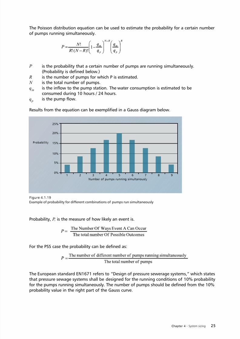
The Poisson distribution equation can be used to estimate the probability for a certain numberof pumps running simultaneously.
P is the probability that a certain number of pumps are running simultaneously.(Probability is defined below.)
R is the number of pumps for which P is estimated. N is the total number of pumps.q
in is the inflow to the pump station. The water consumption is estimated to be
consumed during 10 hours / 24 hours.q p is the pump flow.
Results from the equation can be exemplified in a Gauss diagram below.
Probability, P, is the measure of how likely an event is.
For the PSS case the probability can be defined as:
The European standard EN1671 refers to “Design of pressure sewerage systems,” which statesthat pressure sewage systems shall be designed for the running conditions of 10% probabilityfor the pumps running simultaneously. The number of pumps should be defined from the 10%probability value in the right part of the Gauss curve.
Figure 4.1.19
Example of probability for different combinations of pumps run simultaneously
0%
5%
10%
Probability
Number of pumps running simultanously
1 2 3 4 5 6 7 8 9
15%
20%
25%

7/18/2019 Pumping Handbook
http://slidepdf.com/reader/full/pumping-handbook 34/80
26 Chapter 4 – System sizing
The standard also states that for small systems the running probability case of zero pumpsrunning should be excluded from the estimation. If the probability of one pump running is higher
than 80%, the design case is one pump (otherwise it is the design case corresponding to approx-imately 10% probability).
The system should be designed for a worst-case scenario, which is usually the design number ofpumps located in the most remote points of the same branch running at high pressures all theway from the remote points to the outlet. Please note that it is conservative design criteria; theprobability of these specific pumps running simultaneously is lower than 10%.
Software used by Flygt engineers – called RioGl – estimates how frequently pumps run simul-taneously. Duty situations with one pump, two pumps, three or more that occur daily must bedesigned for; design situations occurring only once a week can be overlooked.
References:Design and performance of PRESSURE SEWERAGE SYSTEMS, Peter Söderlund, Lennart Jönsson,Peter Nilsson. Department of Water Resources Engineering Lund Institute of Technology, LundUniversity Sweden, Report No 7180
4.1.8 Rational Method for establishing design flows in PSS
The Rational method is described in detail in the US handbook EPA Manual 625/1-91/024. TheRational method can be logically applied when either centrifugal pumps or progressive cavitypumps are used. For the Rational method the simplified equation below is easy to use and easyto modify to suit project needs.
Q = AN + B
Q = Design flow (gpm) A = A coefficient selected by the engineer, typically 0.5 which includes
the probability for number of pumps running simultaneously N = Number of EDUs
B = A factor selected by the engineer, typically 20 PC {9-15} Centrifugal {12-25}
Figure 4.1.20
Example of a large PSS where the probability of approximately 10% indicates that the design
should include seven pumps running simultaneously.
0%
5%
10%
Probability
Number of pumps running simultanously
1 2 3 4 5 6 7 8 9
15%
20%
25%

7/18/2019 Pumping Handbook
http://slidepdf.com/reader/full/pumping-handbook 35/80
27Chapter 4 – System sizing
The equation is normally expressed as Q=0.5N+20. However that may vary to account for anincrease in water consumption and correspondingly high wastewater flows.
4.1.9 Peak Flow method
The Peak Flow method is described in “Design and performance of Pressure Sewerage Systems”by Peter Söderlund, Lennart Jönsson, Peter Nilsson.
The Peak Flow method of calculating the design flow in the pipes has been used in Germanyfor many years. It uses the peak flow per inhabitant, multiplied by the number of inhabitantsconnected to the system.
Equation used: q = VW / 10 / 3600 * 1.5 * NI [l/s] (4)
Where q is the average produced peak waste flow.
VW is the produced wastewater per inhabitant per day (usually about 100-250 l).The number 10 is used to distribute this flow within 10 hours, which usually is the averagenumber of wastewater producing hours (this value can vary from about eight to about 12 hours).
The 3600 figure represents one per second (instead of one per hour).NI is the number of connected inhabitants.
The design flow (qd) for each pipe uses the above calculated flow, adjusted to the closest number
of pump design flows.
4.1.10 Probability theory
Probability method is the branch of mathematics concerned with analysis of random phenomena.
The central objects of probability theory are random variables, stochastic processes and events:mathematical abstractions of non-deterministic events or measured quantities that may eitherbe single occurrences or evolve over time in an apparently random fashion. Although an
individual coin toss or the roll of a die is a random event, if repeated many times the sequenceof random events will exhibit certain statistical patterns, which can be studied and predicted.Two representative mathematical results describing such patterns are the law of large numbers
and the central limit theorem.

7/18/2019 Pumping Handbook
http://slidepdf.com/reader/full/pumping-handbook 36/80
28 Chapter 4 – System sizing
Figure 4.1.21
Example of water consumption in different countries
Determining water consumption
The water consumption to be used when designing PSS comes mostly from local standards.Below is an example:
Average water use per person per day
US
0 600
l/day
300
Australia
Italy
Spain
Norway
France
Austria
Denmark
Germany
Brazil
Phillippines
UK
India
China
KenyaHaiti

7/18/2019 Pumping Handbook
http://slidepdf.com/reader/full/pumping-handbook 37/80
29Chapter 4 – System sizing
4.2 Distribution network installation tips
This chapter includes advice on the installation of pressure sewage system piping. Detailedinformation on pipe installation requirements can be supplied by pipe suppliers. Air pockettransportation in descending pipe inclination is explained in Chapter 4.1.5.
To ensure a long and reliable system life, pipe suppliers meet certain conditions, such as a require-ment to pack sand around pipes for in-ground pipe installation. This chapter also includes tipson related hydraulic issues.
4.2.1 Profile recommendations
Inlet pipe to the tank
The liquid is transported from the house to the tank by a gravity pipe. Local regulationstypically define the pipe diameter as 4 inches (or 100 mm). To ensure transportation of solids,this pipe should descend at least 1:100 (1 cm slope for every m of pipe) and avoid sharp bendswhere solids can become stuck.
Elevation requirements
For installations in cold climates, pipes must be installed deep enough to prevent the liquidfrom freezing. Alternatively, an electrical heating cable can be installed along the pipe andbe controlled according to the outside temperature. An insulation box should also be usedto minimize heating demands and energy consumption.
As in all pumping systems with peaks, vacuums can occur under certain conditions. If the peak ishigher than 10 m above the outlet, special consideration should be given in the network design.
Figure 4.2.1
Vaccum bubbles can occur in pipe
systems with high peaks.
For pipe systems in which the outlet is below the pump station, a siphon breaker in the pumpstation is needed. This is described in chapter 4.5.
Entrained air or gas should be pumped out of the pipe system. As pumps in PSS applicationsonly operate for short periods, it is necessary to check that the liquid is transported long enoughto pass the next elevation low point in the pipe. Otherwise, it will return to the peak when theliquid stops its movement. If checking is not possible, installation of an air release valve in thepeak should be considered.
<33 feet, 10 m

7/18/2019 Pumping Handbook
http://slidepdf.com/reader/full/pumping-handbook 38/80
30 Chapter 4 – System sizing
4.2.2 Pipe installation tips
A carefully performed pipe installation will prolong the life of a pipe system. Pipe supplierscan provide recommendations or advice on required local standards, such as trench evennessand trench width, minimum pipe bending radius, packing and filling methods, rock crack sealing,
installation depth (to avoid freezing at low temperatures), and sand or gravel quality for
packing around the pipe.
Figure 4.2.2
Liquid flow direction from left to
right. The marked area shows the
minimum distance the wastewatershould be transported for one pumpcycle to avoid a gas bubble return-
ing to the peak of the pipe after the
pump has stopped.
When bending the pipe, stresses will be built into the material. To ensure that pipe life isnot reduced, it should have a minimum radius defined by the pipe manufacturer. Below is an
example of those recommendations.
Figure 4.2.3
Example of sewage pipe installation.
Figure 4.2.4
Example of minimum pipe bending
radius
Reference: Uponor teknisk Handbok,Tryckrörsystem, 2008
Temperature
-20˚C to + 10 25 x ϕ pipe
above 11˚C 22 x ϕ pipe

7/18/2019 Pumping Handbook
http://slidepdf.com/reader/full/pumping-handbook 39/80
31Chapter 4 – System sizing
Figure 4.2.5
Pipe connection from the household
to the main pipe. Make sure the
connections are rightly connect-ed according to the direction of the
flow, it can be difficult to see the
pump direction of the water.
4.2.3 Pipe dimensions and pressure class definition
The following are pipe standard explanations:Standard dimension ratio (SDR) defines the ratio nominal diameter (outer pipe diameter) andpipe wall thickness.
The pressure class, PN, defines the maximum pressure (bar) at 20 ˚C average temperature. TheFlygt PC grinder M3068.175 has its maximum pressure head at 60 m (200 ft), but it can pumpfor short periods of time at higher head – a fact that should be taken into consideration whenselecting the pipe pressure class.
Below is an example of the dimensions of a PSS discharge pipe:
Nominal diameter(mm, inch)
Wall thickness (mm)
32, 1.3 3
40, 1.6 3.7
50, 2 4.6
63, 2.5 5.8
75, 3 6.8
90, 3,5 8.2
110, 4.3 10
Figure 4.2.6
Uponor pressure pipe PE80,
PN 10, SDR 11.
Ensure smooth flow deflections, for example in pipe connections.

7/18/2019 Pumping Handbook
http://slidepdf.com/reader/full/pumping-handbook 40/80
32 Chapter 4 – System sizing
4.3 Control and Supervision strategies
The following chapter exemplifies different monitoring and control solutions for different userneeds. Typical features and benefits needed for the design of a reliable PSS system are listed andgrouped in solutions to meet different customer needs.
On average, a pump in a pressure sewage system is started and stopped a few times each dayfor a total running time of approximately 10-20 minutes.
A pump must be controlled in order for it to fulfil its required duty. This is usually achieved inwastewater pumping (with low flows) through the use of on-off water level regulation. In a PSSapplication the wastewater enters a pump sump and the pump is started and stopped from thecontrols at different liquid levels. The controls measure the pressure at the different liquid levelseither constantly, analogically, or by starting or stopping the pump after a signal from a startor stop-level switch when the liquid reaches certain levels. The control strategy can be moresophisticated, increasing the intelligence, access and control of the pump system to coveri.e. power failure, increased pipe pressure...
The pump is also monitored to protect it from damage or to protect the pump station fromflooding, a situation that can prove detrimental to the environment. There may also be a needto document the pumping history (i.e. running hours, number of starts, etc.) since the pumpstation may be located in environmentally sensitive areas. Whether for summer residences orpermanent households, there are different technical solutions available to fulfil the requirements
cost efficiently.
Functionalities and features for a reliable monitoring and control solutioncan be summarized as follows:• Controller, alarming and monitoring function integrated in one unit• Easy access and overview of station alarms, status, logging and type• All parameters can easily be changed (without need for extra display or external
resources) allowing for individual settings for optimal pump operation• Secure reliability and long lifetime• Maintenance run after long periods of system rest• Power-on Delay after power failure• Maximum Run Time for a Pump for unnecessary pumping• Early warning system, to prevent emergency call–outs
• Different ways of communication• GSM, GPRS, PSTN, Radio, LON, SCADA system•
Built in monitoring• Remote Service management
4.3.1 PSS Monitoring & Control solutions
The following are three (3) examples of solutions to fulfil different functional requirementssuch as different type of alarms, telemetric surveillance and pressure monitoring.
Solution 1, Simple and robust
The pump is started and stopped by a level regulator. If unwanted solids enter the tank and
both block and stop the pump, the liquid level will rise until the high level alarm is activated(light and sound). This is a typical simple installation for a seasonal house or a permanent house-hold without any need for remote surveillance or pumping data logging.

7/18/2019 Pumping Handbook
http://slidepdf.com/reader/full/pumping-handbook 41/80
33Chapter 4 – System sizing
Open Bell
ATU 001
Figure 4.3.1
This package consists of a 1.1 kW, 1.5 HP, centrifugal grinderpump with an on-off level regulator included, a manual starter
(Flygt FGC 010) a high liquid level switch and an alarm buzzer
box (Flygt ATU 001). The high level switch together with ATU
001 provides a flooding warning by alarming the household.
Figure 4.3.2
The control unit (Flygt FGC 200) monitors
and controls pump and high liquid level.
The FGC 200 and ATU001 unit sounds foralarms such as power failure, high liquid
level, or overly long pump running cycles.
Solution 2, Smart and dedicated
The pump is controlled and monitored by the control unit (such as a Flygt FGC 200). The liquidlevel is measured constantly and determines when the pump starts and stops. Start and stoplevels can be adjusted in the pump controller. Running information such as liquid level, alarmlog, pump current, running hours and number of starts is also stored. When an alarm sounds, alight and sound signal is activated in the control unit and ATU 001.
FGC010
High level switch
FGC 200 Range
High level switch
ATU 001
Option

7/18/2019 Pumping Handbook
http://slidepdf.com/reader/full/pumping-handbook 42/80
34 Chapter 4 – System sizing
Open Bell
High level switch
Figure 4.3.3
The control unit (Flygt FGC300) monitors, controls and
also remotely communicates with a SCADA system.The
intelligent and flexible controller has built-in contactors
and can be equipped with main breakers and a modemto send an alarm to a mobile phone.
Depending on the level of complexity and user needs, functionalities and features for the threemonitoring and control packaged solutions are explained more thoroughly below:
Solution 1: Simple & Robust
Feature Functionality
Stationary hand-operated3-phase starter for D-O-Lstart of pumps
Manual starter for 1 pump up to 7,0 kW(i.e. Flygt FGC 010).
Simple alarm distributionAudible alarm unit is a compact battery operatedunit that will give summary alarm i.e. Flygt ATU 001.It can be equipped with DC supply to save batteries.
Solution 3. Intelligent with Communication
This solution has the same functionalities as in solution 2 but with different types of commu-nication possibilities such as GSM. It is also designed for a maximum of two pumps, such asin demanding applications with several houses connected to one pump station. This solutioncan be used in instances where high reliability, control, logging and communication is required.
FGC 300 Rangewith communication
ATU 001
Option
7/18/2019 Pumping Handbook
http://slidepdf.com/reader/full/pumping-handbook 43/80
35Chapter 4 – System sizing
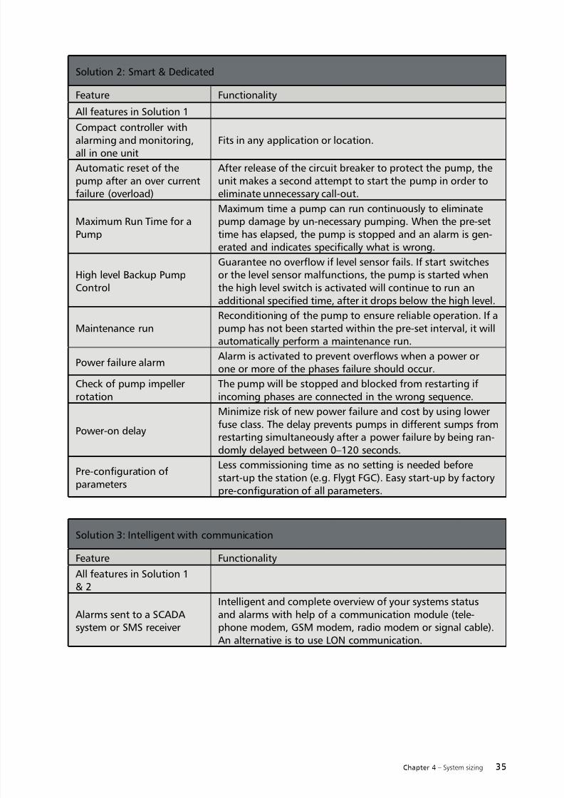
Solution 2: Smart & Dedicated
Feature Functionality
All features in Solution 1
Compact controller with
alarming and monitoring,all in one unit
Fits in any application or location.
Automatic reset of thepump after an over currentfailure (overload)
After release of the circuit breaker to protect the pump, theunit makes a second attempt to start the pump in order toeliminate unnecessary call-out.
Maximum Run Time for aPump
Maximum time a pump can run continuously to eliminatepump damage by un-necessary pumping. When the pre-settime has elapsed, the pump is stopped and an alarm is gen-erated and indicates specifically what is wrong.
High level Backup PumpControl
Guarantee no overflow if level sensor fails. If start switches
or the level sensor malfunctions, the pump is started whenthe high level switch is activated will continue to run anadditional specified time, after it drops below the high level.
Maintenance runReconditioning of the pump to ensure reliable operation. If apump has not been started within the pre-set interval, it willautomatically perform a maintenance run.
Power failure alarmAlarm is activated to prevent overflows when a power orone or more of the phases failure should occur.
Check of pump impellerrotation
The pump will be stopped and blocked from restarting ifincoming phases are connected in the wrong sequence.
Power-on delay
Minimize risk of new power failure and cost by using lowerfuse class. The delay prevents pumps in different sumps fromrestarting simultaneously after a power failure by being ran-domly delayed between 0–120 seconds.
Pre-configuration ofparameters
Less commissioning time as no setting is needed beforestart-up the station (e.g. Flygt FGC). Easy start-up by factorypre-configuration of all parameters.
Solution 3: Intelligent with communication
Feature FunctionalityAll features in Solution 1& 2
Alarms sent to a SCADAsystem or SMS receiver
Intelligent and complete overview of your systems statusand alarms with help of a communication module (tele-phone modem, GSM modem, radio modem or signal cable).An alternative is to use LON communication.

7/18/2019 Pumping Handbook
http://slidepdf.com/reader/full/pumping-handbook 44/80
36 Chapter 4 – System sizing
4.4 Tank design
The following chapter describes the functionality of the tank and the tank components’
functionalities.
The tank collects a household’s sewage from a gravity pipe. Typical water consumption levelsare listed in chapter 4.1.10. When the liquid reaches a certain level, the pump starts and lowersthe level until the liquid reaches a set stop level. This is a very reliable way of controlling waste-water transport (from the household to the pressure sewage system).
To ensure reliable pumping, the tank equipment should meet thefollowing requirements:• According to the European standards, the tank should have an emergency storage
volume of at least 25% of the daily water consumption in the household (to becontinued above the normal start level). This is to prevent flooding, for example,during power supply outages.
• The design must prevent freezing in the piping.• The tank must remain fixed in the ground even in the presence of high water
tables. Ground water will put pressure on the tank, which can rise if not properly
anchored in the ground.• The tank equipment must be easy to install, inspect and service.• It must have a long-lasting design and be built with corrosion-resistant materials.• It must have a smooth, rounded interior shape to prevent the collection of
sediment and debris.• It must be lightweight and have a flexible design for easy installation at
different depths.• The design must respect local regulations or preferences that may require the
tank to have a ventilation pipe.
When several households (typically more than five) are connected to the same tank, dual pumps
are often used for extra safety.
Figure 4.4.1
Elevation view of a PSS package
installed outside a household

7/18/2019 Pumping Handbook
http://slidepdf.com/reader/full/pumping-handbook 45/80
37Chapter 4 – System sizing
The pump is started and stopped by a signal from either on/off level regulators or from a pressure
transducer. A high-level alarm regulator can also be used to avoid the risk of flooding in instances
in which the pump could fail due to the introduction of unexpected objects into the system.
The pump can be installed hanging inside the pressure pipe, either double-bar guided or stand-ing on the bottom with a hose connection to the pressure pipe. The installation preference varies
between countries.
Figure 4.4.2
Flygt PC grinder M3068 installed on a double-guide
bar system, from Flygt-USA and denominated asP-installation, (discharge connection).
Figure 4.4.3
Flygt PC grinder M3068 installed standing on
the tank bottom and connected to the pressure
pipe with a pressure house from Flygt-Australia,denominated as F-installation (free standing).

7/18/2019 Pumping Handbook
http://slidepdf.com/reader/full/pumping-handbook 46/80
38 Chapter 4 – System sizing
Accessories in the tank include a check valve, a shut-off valve and, in some cases, a siphon breaker
and a high-pressure water flush connection.
The check valve prevents backflow from the pressure sewage system into the tank. Reliable checkvalves are of outmost importance to ensure the system works properly. Double-check valvescan also be used: one in the tank and one at the boundary of the building plot.
When water consumption is low, wastewater can remain in the pipe system for long periodsof time. Occasional fresh water flushing of the pressure pipes may be necessary to prevent thewastewater from becoming septic.
The shut-off valve in the tank is used when maintenance of the equipment in the tank takesplace (to isolate the tank from the pressure sewage system). A shut-off valve installed at theboundary of the building plot is also used when installing the tank.
The use of siphon breakers differs according to markets. When the outlet is below any pressuresewage system pump station, however, a siphon breaker should always be used in that pumpstation. Siphon breakers are discussed in the chapter 4.5, together with the air release valve.
Figure 4.4.4
Flygt centrifugal grinder M3068
installed hanging inside the tank,denominated as H-installation
(hook-up).

7/18/2019 Pumping Handbook
http://slidepdf.com/reader/full/pumping-handbook 47/80
39Chapter 4 – System sizing
4.5 Air-release valves, Siphon breakers
Air-release valves
Air can enter into the pipe system and/or gas can develop inside the pipe from biologicalactivity. For pipes in topographies with significant peaks, entrained or developed gas bubblescan accumulate in the peaks if the liquid velocity in the descending pipes is insufficient
for transportation to the outlet. The accumulated gas can increase the pump system head loss,thus causing problems in the pressure sewage system (PSS). To release the gas, air release valvescan be installed at the peaks of the pipes. These automatically open when gas is present andclose as soon as the gas is expelled.
To ensure reliable and trouble-free operation of the PSS, air release valves that are specificallydesigned for wastewater should be used. Please see suppliers’ recommendations.
Sufficient velocity to transport air in descending pipes is recommended in pressure sewagesystems. This is described in more detail in Chapter 4.1.5.
Siphon breaker
When the system outlet is located at a lower elevation than the liquid level in some pumpstations, those stations and their corresponding pipes can be emptied by siphon action – undersub pressure – until air entrains, breaking the siphon. The entrained air could cause air-lock inthe pump, creating a need for manual priming before the pump can be restarted. A siphonbreaker is an air inlet valve that opens under pressure in the pipe and stops the liquid flow.As air is released into the pipe, the water velocity must be high enough when the pump isrunning to transport the air pockets to the outlet at the declining pipe slopes.
The siphon breaker can be placed either upstream or downstream of the check valve.
Figure 4.5.1
Siphone breaker located upstreamof the check valve. Image from PSS
package, Flygt- USA.
Figure 4.5.2
Air release valve located downstream
of the check valve. Image from PSSpackage, Flygt- Australia.

7/18/2019 Pumping Handbook
http://slidepdf.com/reader/full/pumping-handbook 48/80
40 Chapter 5 – Design tools
Several engineering tools are available from us. Below are short descriptions of PSS softwarepossibilities; more information can be found on our website.
RioGl software can be used to select optimal pump and pipe sizes. SECAD, which includesdimensional drawings of the Flygt 3000 pump assortment, can be used to design large
pump stations and includes other Flygt products that are not used in PSS applications. SelectITT includes data and information about pumps, pumping stations and monitoring and
control equipment.
A map or aerial photo is imported in jpg format. After the placement of pump stations andelevations are entered, RioGl proposes solutions with regard to pump types and pipe
diameters. Those solutions are contained in a report that also includes wastewater retentiontimes, liquid velocities and pump duty points.
Other design tools with similar functionality are also available, including KY Pipe 2010, which isused by Flygt- USA.
Design tools
Chapter 5
Figure 5.1
Pressure sewage system design inputin RioGl. The software reports liquid
velocities in each pipe when one or
several pumps are running simulta-
neously.

7/18/2019 Pumping Handbook
http://slidepdf.com/reader/full/pumping-handbook 49/80
41Chapter 5 – Design tools
Figure 5.2
Secad input interface. The tank typeand pump type is defined.
Figure 5.3
Secad produces a dimensional drawing.

7/18/2019 Pumping Handbook
http://slidepdf.com/reader/full/pumping-handbook 50/80
42 Chapter 5 – Design tools
Figure 5.5
KY PIPE 2010 used to estimate pipe
flow velocity
Figure 5.4
The web-based software Select ITT
includes product data for pumps,
tanks, monitoring and controlequipment used in PSS installa-
tions. Shown here is a consultant
specification template.

7/18/2019 Pumping Handbook
http://slidepdf.com/reader/full/pumping-handbook 51/80
43Chapter 5 – Design tools

7/18/2019 Pumping Handbook
http://slidepdf.com/reader/full/pumping-handbook 52/80
44 Chapter 6 – Description of hydraulic end types
Described below are the different impeller types used in PSS applications. Impeller type pref-erences vary, however, between countries. Flygt N-impellers are the preferred choice in liftpump stations for receiving wastewater from the PSS system. N-impellers are not described inthis handbook. This handbook is limited to the PSS application where a grinding of the liquidusually is required.
Included in this chapter is a comparison between the use of vortex / recessed and Flygt M-grinderhydraulic ends. In particular, the hydraulic ends are evaluated from the perspective of theprimary customer who requires a system that operates without manual labor.
Grinder pumps have a mechanical cutting device outside the pump inlet which is independentlydesigned from the hydraulic end type. The cutting device is normally made of an abrasiveresistant material.
In the context that follows, the hydraulic end will be referred to as impeller, excluding thecutting device.
6.1 Centrifugal grinder pumps
The hydraulic ends used in centrifugal grinder pumps are multi-vane impellers (Flygt type M)or, in the US, recessed impellers.
Multi-vane impeller
The impeller unit of the grinder pump, with Flygt denomination M, is specifically designed tohandle the rigors of pressurized sewage systems. The pump inlet is equipped with a cutting device
that grinds particles into a low viscous liquid that can be pumped through the system’s narrow
pipes, which measure 32–50 mm or 1.25–2 inch in diameter.
For normal PSS operation, Flygt grinder pumps can be operated at all duty points along theirperformance curves, including the vertical portions. Centrifugal grinder pump perfor-mancecurves often have horizontal and vertical portions.
The power uptake data adheres to the dictum, “What you see is what you get”. The performancecurve shows the power uptake at different duties. Since the maximum power is lower than therated power for all duties on the performance curve, there is no need to consider overloads when
selecting the pump. Please also see chapter 8.1.
Description of hydraulic end types
Chapter 6

7/18/2019 Pumping Handbook
http://slidepdf.com/reader/full/pumping-handbook 53/80
45Chapter 6 – Description of hydraulic end types
Recessed / Vortex impeller
With a vortex pump, flow through the unit is produced not by the actual impeller but by therapidly rotating vortex that is created by the impeller.
Figure 6.2
The D-impeller is a vortex-type
impeller and single volute pumpcasing with large throughlets for
sludge containing solids and fibers.
A cutting device is not included inthe picture.
Figure 6.1
The first choice for houses which employ slender plastic
pipes. The grinder impeller is supplied with a cutting device
that grinds the solids in the wastewater. As the solids are
ground, no wear occurs on the impeller.

7/18/2019 Pumping Handbook
http://slidepdf.com/reader/full/pumping-handbook 54/80
46 Chapter 6 – Description of hydraulic end types
6.1.1 Comparison of multi-vane and recessed/vortex impellers
Pumping operation times in PSS applications are short (i.e. 10 minutes a day), thus energycosts are negligible making motor size less important. However, the restricting factor for a PSSis maximum amperage consumption because the electrical installation must be sized for therated (maximum) amperage. Costs, relative to pump, can increase substantially due to electrical
installation if the amperage exceeds a certain amount. The dependency between efficiency andamperage is described below (power consumption is proportional to amperage consumption).The required shaft power for a certain duty point is:
In which P2 is shaft power, H is head, Q is pumped flow, ρ is liquid density, g is constantof gravity, and η
Hydraulic is hydraulic efficiency.
As a result, lower hydraulic efficiency requires a larger motor and higher amperage con-
sumption to achieve a certain performance curve.
The hydraulic efficiency (excluding the grinder mechanism) for multi-vane impellers is slightlyhigher than for vortex impellers. The hydraulic efficiency of the Flygt grinder pump seriesM3000 includes the power consumption for the grinder device.
Conclusion
A vortex pump is a good choice for sewage pumping where low energy consumption demandcan be neglected. However, the multi-vane grinder pump, due to its slightly higher efficiency,has lower amperage consumption than the vortex. To reduce the installation cost minimizing theamperage consumption is especially important with single-phase power supply.
The multi-vane impeller has proven highly reliable and long-lasting, with more than 300,000 Flygt
M type grinder pumps running in more than 10,000 PSS-systems worldwide.
6.2 Progressive cavity grinder pumps
Progressive cavity pumps belong to the positive displacement-pump type category. They can be
described as follows:
Positive displacement pumps cause fluids to move by trapping and forcing or displacing theminto the discharge pipe. Positive displacement pumps can be further classified according to themechanisms used to move fluids.
Progressive cavity grinder pumps are widely used for pumping materials that are difficult
to move, such as sewage sludge containing large particles. They consist of helical-shaped rotorsthat fit inside rubber sleeves called stators. As the rotor rotates, fluid is gradually forced upthe rubber sleeve to produce a low and stable flow at both low and high heads. The pumpingaction is produced by a corkscrew-shaped rotor that turns in a rubber stator. As the rotor
turns, water trapped in cavities between the rotor and stator progresses through the pump.

7/18/2019 Pumping Handbook
http://slidepdf.com/reader/full/pumping-handbook 55/80
47Chapter 6 – Description of hydraulic end types
The pump cannot run at snoring (air suction at low liquid level) and is more sensitive to wearthan a centrifugal pump.
Figure 6.3
Hydraulic end of the Flygt progressive cavity grinder pump M3068.175.
7/18/2019 Pumping Handbook
http://slidepdf.com/reader/full/pumping-handbook 56/80
48 Chapter 7 – Hydrogen sulfide in PSS
This chapter describes the problems caused by hydrogen sulfide (H2S), its properties, origins andpossible corrective measures.
The formation of hydrogen sulfide (H2S) in sewage systems has long been known as a source ofodor and corrosion problems.
The main problems associated with H2
S are:• At low concentrations it has an unpleasant odor, not unlike that of
rotten eggs, from both the pipes and pump stations. At higher concentrationsthe gas is poisonous.
• It causes corrosion of metal parts in the sewage system, including pipes,installation equipment, sensors, etc.
• It also causes corrosion of concrete in the sewage system, including pipes,pump stations, sump, etc.
• There is a risk of explosion if the concentration of gas is above 4 percent.
H2S is formed by anaerobic processes (absence of oxygen) during the degradation of organicmaterial in the sewage system. It occurs mainly in sewage pipes when the retention time is overlylong. The formation of H2S starts when the amount of oxygen in the wastewater is low (approx-imately below 1 mg/l) and nitrates in the wastewater are consumed.
The main parameters that affect the formation of H2S are: pH, temperature, available oxygen(free or chemically bonded) and retention time in the system (bio-film).
Corrective actions to minimize these problems involve optimization of the system design and/orthe addition of oxygen/air or chemicals into the process.
Different types of systems may have different optimal solutions to eliminate H2S problems.
Minimizing the problem requires careful consideration.
Properties of H2S:
H2S is a colorless gas that is heavier than air and soluble in water. The gas gives a bad odor atlow concentrations, and it is poisonous at higher concentrations, capable of causing severehealth problems and even death.
Hydrogen sulfide in PSS
Chapter 7

7/18/2019 Pumping Handbook
http://slidepdf.com/reader/full/pumping-handbook 57/80
49Chapter 7 – Hydrogen sulfide in PSS
When organic compounds degrade, organic sulfuric compounds are converted into H2S, sulfide(S2-) and hydrogen sulfide ions (HS-).
The volatility of the H2S enables the gas to easily evaporate from liquid to air. The amount ofgas that evaporates into the air depends on the temperature, the concentration of sulfide andthe turbulence of the water.
Corrosion
H2S can cause corrosion on concrete and metal parts in the sewage system according to the fol-lowing reactions:
When water comes in contact with the surface of the pipes, the gas can either diffuse into air-
filled pores in the pipes or dissolve into the water around solid particles and also diffuse into thepipes. If oxygen is present, the H2S is oxidized by bacteria into sulfuric acid which in turn attacksthe material according to the reactions below:
Corrosion of concrete:
H2S + 2 O2 → H2SO4
(Hydrogen sulfide + oxygen → sulfuric acid)
The sulfuric acid reacts with the alkaline cement in the concrete according to:
H2SO4 + CaCO3 → H2O + CO2 + CaSO4(sulfuric acid + cement →water + carbon dioxide + calcium sulfate (gypsum))
Content of H2
S (ppm) in air Human reactions
0.002-0.2 Smell threshold
1 Faint but noticeable smell
3-5 Distinct smell
10 Acceptable sanitary level for 1-day exposure
10-50 Irritation to eye
30 Unpleasant odor
50-100 Eye and respiratory difficulties after 1-hour exposure
100-200
Coughing and eye irritation (The odor disappears after 1–15
minutes. Dizziness occurs after 10–20 minutes.)
150-300 Paralysis of the sense of smell
500-1000 Paralysis of the breathing system and unconsciousness
>1000 Death
Table 7.1
H2S level over 100 ppm (harsh conditions) can occur in pump stations.
Health hazards of H2S

7/18/2019 Pumping Handbook
http://slidepdf.com/reader/full/pumping-handbook 58/80
50 Chapter 7 – Hydrogen sulfide in PSS
The action of sulfuric acid on concrete converts it to a pastry mass consisting largely of calciumsulfate and the residual sand and gravel used to make the pipe.
These reactions occur mainly above the water surface, where there is oxygen available to enablethese chemical reactions.
Corrosion of metals:
H2S reacts with metals according to the reaction:
H2S + metal →metal sulfide + H2
This reaction will/can affect the pipes and the installation equipment in the pump station as wellas electronic components (sensors, etc.) in the stations.
Problematic H2S formation occurs mainly in stationary water systems with low flow where thewater contains organic compounds with sulfate and the water is relatively warm, such as in long,pressurized sewage systems or poorly ventilated gravity sewers.
Origins of sulfides
The formation of H2S in sewage systems is a result of the reduction of sulfates and the
degradation of organic compounds by sulfate-reducing bacteria in anaerobic (oxygen-free)environments. The degradation occurs mainly in the anaerobic zone in the “slime layers” (biofilm) in the sewage pipes. (See figure below.)
Figure 7.2
Illustration of the “slime-layer”zones inside a sewage pipe
Aerobic zone
Anaerobic sulfide producing zone
Inert anaerobic zone
Pipe wall
Sewage stream
Oxygen Nutrients (sulfate
and organic matter)
Sulfide
Slime layer, typically
0.1-1 mm

7/18/2019 Pumping Handbook
http://slidepdf.com/reader/full/pumping-handbook 59/80
51Chapter 7 – Hydrogen sulfide in PSS
The bacteria that promote the formation of H2S are mainly located in the slime layer on theinside of pipes used for wastewater. The thickness of slime layers range from 0.1-1 mm. It is inthat anaerobic (oxygen-free) zone that H2S is formed.
1. As long as there is free oxygen in the sewage, the bacteria in theoxygenated aerobic zone of the slime layer dominate the degradation
of organic material, limiting the H2S formation to minor amounts.
2. When all dissolved oxygen is consumed, the bacteria will dominateand use nitrates as an oxygen source in the degradation process.
3. When all the oxygen in the nitrates is consumed, bacteria in theanaerobic zone will take over the degradation process, resultingin the formation of H2S.
Sulfide exists in wastewater in the state of insoluble sulfides such as ferric sulfide (FeS) and zincsulfide (ZnS) and as dissolved sulfide ions (S2-), hydrogen sulfide ions (HS-) and in the form ofhydrogen sulfide (HS-).
Factors that favor the formation of H2S:• Low concentration of dissolved oxygen. If the content of oxygen is higher than
approx 1.0 mg/l, H2S will not form.•
Low water velocity. The recommended minimum water velocity in pipes is recom-mended to be higher than 0.7 m/s at least once every 24 hours to minimize oravoid the formation of H2S (according to EN 1671, “Pressure Sewerage Systems,outside buildings”).
• Long retention time in the system.• High content of organic sulfur compounds in the sewage.• High water temperature. As a rule of thumb, the rate of sulfide production
increases with approximately 7 percent per degree Celsius up to 30oC, and it isnegligible if the temperature is below 7oC.
• Low pH-value promotes the formation of H2S instead of the ions HS- and S2-,as shown in the figure below. At a pH below 5, the fraction of H2S is about
100 percent and at pH above 9 the fraction of H2S in the water is approximately0 percent. Adding chemicals such as sodium hydroxide will increase pH andthereby minimize the amount of H2S.
Figure 7.3
Schematic illustration of sulfuric
components in water and air inside
a sewage pipe
Sewage
water
Air
H2S + 2 O2 → H2SO4
↑H2S
↑H+
+
S2- + H+ ↔ HS-

7/18/2019 Pumping Handbook
http://slidepdf.com/reader/full/pumping-handbook 60/80
52 Chapter 7 – Hydrogen sulfide in PSS
Guidelines to avoid or minimize the formation of H2S in sewage systems:• Keep the retention time in pressurized sewers as low as possible.• Place the exits of the pressurized sewage for gravity sewers in places where
complaints of odors will be least expected.• Avoid biochemical reduction of sulfur by making air available in both the sewer
and the pump sump.• Select corrosion-resistant materials in the pump station and in sewers.• Add chemicals (see below) or active bacteria.• Inject air/oxygen into the effluent on the delivery side of the pump during
operation.• Ventilate the pump station.• Design for an “anti-splash” barrier at inlets to avoid or minimize the formation
of aerosols which can emit H2S.• Prepare the sewage system for cleaning/removal of the slime layer on the inside
of the pipe walls.• Reduce the consequences (corrosion) of H2S by encouraging its release at the
outlet of the network in a sealed “pre-manhole” made of polyethylene orpolyester/glass fiber separated from the sewage sump. On the walls of the“pre-manhole,” the released H2S oxidizes to form H2SO4 by condensation,and then dissolves and dilutes in the effluent. A good precaution is to protectthe gravity feed pipe from the “pre-manhole” to the pump sump over a distance
of at least 20 meters with PVC-sleeving or other materials to eliminate corrosion.
Addition of chemicals• Nitrates (source of oxygen). Calcium nitrate (i.e., Nutriox®).• Chlorine (sodium chlorite or sodium hypochlorite).• Hydrogen peroxide (produces dissolved oxygen).• Sodium hydroxide (raises pH to 12 for approximately 30 minutes, must be
repeated at intervals).• Iron salts (react with H2S to form ferric sulfide)
Figure 7.4
The pH-dependence of the fractions of H2S and HS- in sewage
Fraction of H2SFraction of HS-
Fraction (%)
0
0.2
0.4
0.6
0.8
1
3 4 5 6 7 8 9 10
pH-value

7/18/2019 Pumping Handbook
http://slidepdf.com/reader/full/pumping-handbook 61/80
53Chapter 7 – Hydrogen sulfide in PSS

7/18/2019 Pumping Handbook
http://slidepdf.com/reader/full/pumping-handbook 62/80

7/18/2019 Pumping Handbook
http://slidepdf.com/reader/full/pumping-handbook 63/80
55Chapter 8 – Abbreviations
8.1 Electrical parameters
M3090 is a 2-hp class grinder pump that is used primarily for pressure sewage systems
(PSS) applications. It complements the centrifugal grinder M3068.170 with higher pressures ofbetween 130 m to a maximum of 230 m. It is the same size as other PSS 2-hp pumps, though itsrated shaft power is 4 kw. The Flygt PSS assortment also includes the progressive cavity pumpM3068.175.
M3090 has the same size, weight, input power uptake and current as other 2-hp centrifugalgrinder brands. Its rated power, 4 or 6 kw, follows the usual rating praxis used for all Flygt pumpsto categorize the size of the pump.
Parameters are needed to specify the required performance – and expected results – for allmechanical equipment. That is also true with regard to pumps. The most common parameterin pumping is the amount of time it takes to transport certain volumes away from the pumpto an outlet of the pipe system – or the ‘required pump flow.’ In commercial applications,flows are often quite large, and energy consumption needs to be minimized in order to get acost-effective solution. In residential applications, such as in pressure sewage systems, the watervolumes to be transported are much smaller and require less energy. However the maximumamperage is important because it defines the size and cost of the electrical installation.
The electrical parameters used in pump system design are described below.
8.1.1 Background
Electrical parameters are used to select the best pump and the proper size of electrical installation
equipment. This chapter also includes background information on shaft power usage for
defining the size of the pump.
Power consumption or input power or power uptake is proportional to supplied voltage andconsumed amperage.
P 1∝ U I [kW or hp]
U [V] is the voltage supplied by the electric net. I [A] is the consumed amperage.
(The power the pump consumes multiplied by the number of running hours determines the totalcost of the electricity bill.)
I and P 1 vary with duty point (head and flow). For centrifugal pumps, including grinder pumps,
amperage and power consumption increase with increasing flow.
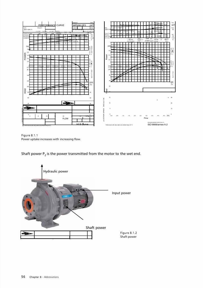
7/18/2019 Pumping Handbook
http://slidepdf.com/reader/full/pumping-handbook 64/80
56 Chapter 8 – Abbreviations
Figure 8.1.1
Power uptake increases with increasing flow.
Figure 8.1.2
Shaft power
u n i x A U T H O R : G P W E B 1
S A C U ( r e v :
7 . 4 9 )
Performance CurveDate Project
1/1-Load 3/4-Load 1/2-Load
Power Factor
Efficiency
Motor Data
Comments Inlet/Outlet
Imp. Throughlet
RatedPower ...
StartingCurrent ...
RatedCurrent ...
RatedSpeed ...
Tot. Mom. ofInertia ...
No. ofBlades
Product Type
Curve No Issue
Motor # Stator Rev
F re q. P ha se s V ol ta ge P ol es
Geart ype Ratio
Performance with clear water and ambient temp 40 °C
MF3068.170 HT
2011-02-07 53- 210 -00- 312 0 10Impeller Diameter
160 mm
13-10-2BB 01Y 10
50 Hz 3 400 V 2
--- ---
0.87
75.5 %
---
0.81
79.0 %
---
0.70
80.5 %
---
-/ 38 mm
6 mm
2.4 kW
24 A
5.3 A
2705 rpm
0.0045 kgm2
10
Flow
[l/s]
H e a d
[m]
P o w e r
[kW]
Eff.[%]
0.0 0.5 1.0 1.5 2.0 2.5 3.0 3.5 4.0 4.5
0
5
10
15
20
25
30
35
0
10
20
30
40
2.0
2.4
2.8
G
G
G
D uty- Po in t F lo w [ l /s ] H ea d [m] Pow er [kW] Eff . [%] (NPSHR)[m]
3. 57 23 .6 2. 53 ( 1. 98 ) 32 .8 ( 41 .9 ) I SO 9 90 6/ an ne x A .2
Guarantee
B.E.P.
B e s t E f f . P o i n t
O * O v e r a l l E f f .
P u m p E f f .
O * I n p u t P
o w e r
S h a f t P o w e r
ISO 9906/annex A.2Guarantee between limits (G) acc. to
F L Y P S 3 . 1 . 6 . 6 ( 2 0 0 9 0 3 1 3 )
PERFORMANCE CURVEDATE PROJECT
1/1-LOAD 3/4-LOAD 1/2-LOAD
POWER FACTOR
EFFICIENCY
MOTOR DATA
COMMENTS INLET/OUTLET
IMP. THROUGHLET
RATEDPOWER .....
STARTINGCURRENT ...
RATEDCURRENT ...
RATEDSPEED .....
TOT.MOM.OFINERTIA ...
NO. OFBLADES
PRODUCT TYPE
CURVE NO ISSUE
MOTOR # STATOR REV
FREQ. PHASES VOLTAGE POLES
G EA RTY PE RA TI O
Performance with clear water and ambient temp 40 °C
MP3090.170 HT
2011-04-11 61 -25 4- 00- 225 0 1IMPELLER DIAMETER
146 mm
15-12-2BB 12- 12
60 Hz 1 230 V 2
--- ---
1.0080.5 %
---
0.9982.5 %
---
0.9682.0 %
---
- / 1.5 inch
---
5.5 hp
96 A
22 A
3475 rpm
0.0060 kgm2
6
FLOW
[USgpm]
H E A D
[ft]
P O W E R
[hp]
EFF.[%]
0 5 10 15 20 25 300
20
40
60
80
100
120
140
0
10
20
30
40
2.0
2.5
3.0
3.5
4.0
DUTY-POINT FLOW[USgpm] HEAD[ft] POWER [hp] EFF. [%] NPSHre[ft]
2 7. 69 1 21 .8 4 .2 3 ( 3. 51 ) 2 0. 2 ( 24 .3 )B.E.P.
B E S T E F F . P O I N T
O * O V E R A L L E F F .
P U M P E F F .
O * I N P U T
P O W E R
S H A F T
P O W E R
HI B Curve
Shaft power
Shaft power P2 is the power transmitted from the motor to the wet end.
Input power
Hydraulic power

7/18/2019 Pumping Handbook
http://slidepdf.com/reader/full/pumping-handbook 65/80
57Chapter 8 – Abbreviations
Figure 8.1.3Centrifugal grinder M3090, typically 1l/s @ 43 m
and 13 Amp / 16 USPGM @ 140 feet, 22 Amp
Historically most pumps and motors have been separated. The required pump flow and headdefined the hydraulic power and, in combination with the hydraulic efficiency, the needed shaftpower. The shaft power (P2) is the power to be transmitted from the motor to the wet end,the interface between the wet end (from one supplier) and the motor (from another supplier),sometimes via a clutch between the wet end (pump) and the motor.
Shaft power [hp,kW]
ηmotor
defines the efficiency of the motor. It varies with the loading of the motor. The motorefficiencyis the difference between the total efficiency and the hydraulic efficiency (see thecurve above).
Hydraulic power is proportional to pumped flow [USGPM, l/s] and produced pressure, head[m, feet]
P hyraulic
∝ QH [hp,kW]
The efficiency of the wet end is defined as:
The maximum hydraulic efficiency a particular pump can achieve is denoted as best efficiencypoint (BEP). (See performance curve above.)The total efficiency for the pump is defined as:
or
Detailed data for a specific pump can be supplied by Flygt.
For submersible pumps, in which the wet end and the motor are integrated, the nameplatehorsepower indicates the maximum shaft power that the motor can handle in continuousoperation. However, the input power should also be considered for pump selection. When defining
the shaft power to be included in the product data, the shaft power has to be calculated ormeasured with the pump taken apart.

7/18/2019 Pumping Handbook
http://slidepdf.com/reader/full/pumping-handbook 66/80
58 Chapter 8 – Abbreviations
P2 at maximum input power allowed determines the rated power. The rated amperage
corresponds to the maximum power input and defines the needed circuit breaker size andwiring sizes
An electric motor has a limit on how much electric power it can transfer to shaft power with-out being damaged by high temperature. In intermittent duty electric motors can handle higher
loads; thus, intermittent-duty equipment can be rated higher.
8.1.2 Power ratings at different duty conditions
Different ratings are used to define possible overload during shorter periods. In the U.S. theservice factor (SF) is used to define how much additional power a motor can be loaded with.For example, a SF of 1.25 at a 2-hp motor can be overloaded up to 2.5 hp during shorter peri-ods. An alternative definition is the International IEC duty cycle. S1 applies to continuous duty(i.e.) the motor works at a constant load for enough time to reach temperature equilibrium).S3 is the rated power for intermittent periodic duty. Temperature equilibrium is never reached;starting current has little effect on temperature rise. S3 can be used for normal PSS installations.
8.1.3 The essential parameters
The requirements on a pump for pressure sewage systems are:1. Sufficient flow to ensure enough scour in the pipe2. Sufficient head to overcome the geodetic head and the dynamic
head generated in 1;3. Low amperage consumption to ensure smaller components in
the control panel, minimizing installation cost. M3090 is availablewith a 15-amperage rating as well as 22 amperage in singlephase (60 Hz).
8.1.4 Conclusions
The name plating of the unit follows the typical Flygt convention Competitor units may showa lower 2 hp – thus higher input power and amperage. The Flygt MP3090 has comparablepower consumption and requires equivalent components for the electrical panel as other
centrifugal grinder pumps.

7/18/2019 Pumping Handbook
http://slidepdf.com/reader/full/pumping-handbook 67/80
59Chapter 8 – Abbreviations
8.2 Flygt PSS assortment
For more information regarding PSS packages. Please contact our local Flygt representative orvisit our website www.flygt.com

7/18/2019 Pumping Handbook
http://slidepdf.com/reader/full/pumping-handbook 68/80
60 Chapter 8 – Abbreviations
8.3 Pump and pipe design guideline
Many decisions must be made when designing a PSS system. Some are centrifugal grinderpump and/or PC grinder pump, telemetric monitoring or not. Other decisions are for examplesophistication level for the alarm for possible emergency conditions. Also future extension/expansion of the PSS system needs to be considered, which can affect pipe sizes, etc.
This chapter includes both PSS pump size and pipe size selection method to be used as aguideline when designing a system (i.e. the selection of pump and pipe sizes). Each step inthe guideline refers to additional information in corresponding chapters. Prior to estimatinghydraulic conditions, (pressure heads and flows) the type of pump should be decided, i.e.Centrifugal or a PC grinder pumps. Their respective pros and cons are described in chapter 4.1.2.
The checklist in chapter 8.4 complements the following methodology for supporting the designwork. The methodology defines the needed pump capacity and pipe dimensions according tothe hydraulic conditions that will occur.
Guidelines to choose the optimal monitoring and control solution based on user preferences canbe found in chapter 4.3. Requirements to be considered when defining the tank such as buffervolume for emergency conditions are described in chapter 4.4.
There can also be additional local requirements such as a need for heating cables, emergencydischarge, pump snoring, etc.

7/18/2019 Pumping Handbook
http://slidepdf.com/reader/full/pumping-handbook 69/80
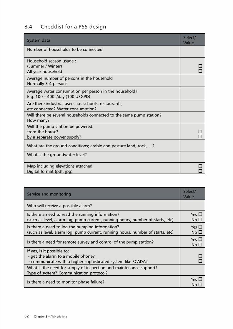
7/18/2019 Pumping Handbook
http://slidepdf.com/reader/full/pumping-handbook 70/80
62 Chapter 8 – Abbreviations
8.4 Checklist for a PSS design
System dataSelect/ Value
Number of households to be connected
Household season usage :(Summer / Winter)All year household
o
o
Average number of persons in the householdNormally 3-4 persons
Average water consumption per person in the household?E.g. 100 – 400 l/day (100 USGPD)
Are there industrial users, i.e. schools, restaurants,etc connected? Water consumption?
Will there be several households connected to the same pump station?How many?
Will the pump station be powered:from the house?by a separate power supply?
o
o
What are the ground conditions; arable and pasture land, rock, …?
What is the groundwater level?
Map including elevations attached
Digital format (pdf, jpg)
o
o
Service and monitoringSelect/ Value
Who will receive a possible alarm?
Is there a need to read the running information?(such as level, alarm log, pump current, running hours, number of starts, etc)
YesoNoo
Is there a need to log the pumping information?
(such as level, alarm log, pump current, running hours, number of starts, etc)
Yeso
Noo
Is there a need for remote survey and control of the pump station? YesoNoo
If yes, is it possible to: - get the alarm to a mobile phone? - communicate with a higher sophisticated system like SCADA?
o
o
What is the need for supply of inspection and maintenance support?Type of system? Communication protocol?
Is there a need to monitor phase failure? YesoNoo

7/18/2019 Pumping Handbook
http://slidepdf.com/reader/full/pumping-handbook 71/80
63Chapter 8 – Abbreviations
Scope of deliverySelect/ Value
Comments
What is the required scope of delivery?Equipment only:
Complete contract:
Other, please specifiy:
o
oo
Who executes the excavation?
Who executes the electrical,pipe and pump station installation?
Who executes the start up?
Scope of delivery from consultant
Function Select/ Value
Comments
Please verify that there are shut off valves at the reticula-tion pipe?
YesoNoo
Will drinking water piping be installed? YesoNoo
Diameter?
Will heating cable be installed? YesoNoo
Temperature control of the heating cable?Earth fault breaker included?
o o
Are frost isolation boxes used? YesoNoo
The dimension of thebox depends on the pipediameter
Sewer and water pipe information (for complete contract)Household piping
FunctionSelect/ Value
Comments
Is there an existing reticulation pipe? YesoNoo
Reticulation pipe dimension?Material?
Pressure class?
Existing heating cable? YesoNoo
Temperature control of the heating cable?Earth fault breaker included?
o o
Are frost isolation boxes used? YesoNoo
The dimension of thebox depends on the pipediameter
Reticulation piping data

7/18/2019 Pumping Handbook
http://slidepdf.com/reader/full/pumping-handbook 72/80
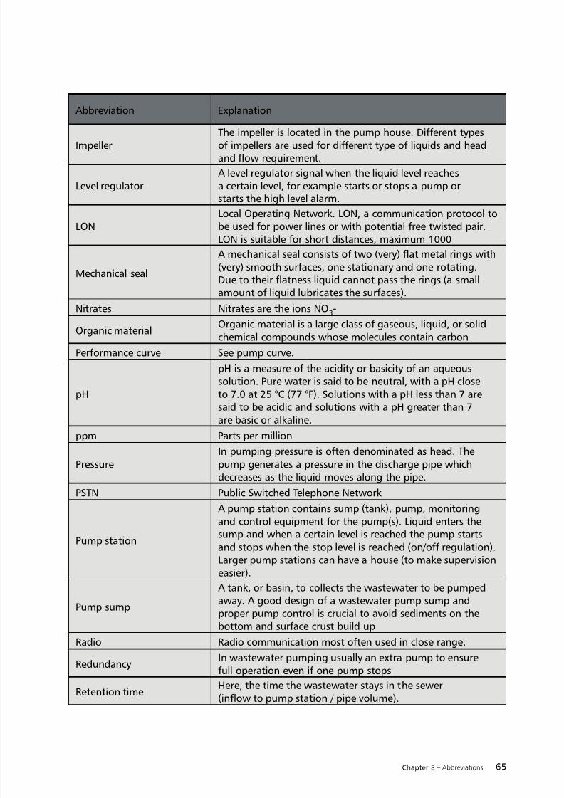
7/18/2019 Pumping Handbook
http://slidepdf.com/reader/full/pumping-handbook 73/80
65Chapter 8 – Abbreviations
ImpellerThe impeller is located in the pump house. Different typesof impellers are used for different type of liquids and headand flow requirement.
Level regulatorA level regulator signal when the liquid level reachesa certain level, for example starts or stops a pump orstarts the high level alarm.
LONLocal Operating Network. LON, a communication protocol tobe used for power lines or with potential free twisted pair.LON is suitable for short distances, maximum 1000
Mechanical seal
A mechanical seal consists of two (very) flat metal rings with(very) smooth surfaces, one stationary and one rotating.
Due to their flatness liquid cannot pass the rings (a smallamount of liquid lubricates the surfaces).
Nitrates Nitrates are the ions NO3-
Organic materialOrganic material is a large class of gaseous, liquid, or solidchemical compounds whose molecules contain carbon
Performance curve See pump curve.
pH
pH is a measure of the acidity or basicity of an aqueoussolution. Pure water is said to be neutral, with a pH closeto 7.0 at 25 °C (77 °F). Solutions with a pH less than 7 aresaid to be acidic and solutions with a pH greater than 7
are basic or alkaline.ppm Parts per million
PressureIn pumping pressure is often denominated as head. Thepump generates a pressure in the discharge pipe whichdecreases as the liquid moves along the pipe.
PSTN Public Switched Telephone Network
Pump station
A pump station contains sump (tank), pump, monitoringand control equipment for the pump(s). Liquid enters thesump and when a certain level is reached the pump startsand stops when the stop level is reached (on/off regulation).
Larger pump stations can have a house (to make supervisioneasier).
Pump sump
A tank, or basin, to collects the wastewater to be pumpedaway. A good design of a wastewater pump sump andproper pump control is crucial to avoid sediments on thebottom and surface crust build up
Radio Radio communication most often used in close range.
RedundancyIn wastewater pumping usually an extra pump to ensurefull operation even if one pump stops
Retention timeHere, the time the wastewater stays in the sewer
(inflow to pump station / pipe volume).
Abbreviation Explanation

7/18/2019 Pumping Handbook
http://slidepdf.com/reader/full/pumping-handbook 74/80
66 Chapter 8 – Abbreviations
SCADA system
Supervisory Control And Data Acquisition. By connectingRTUs (Remote Terminal Units) you can precisely andeffectively monitor and control the flow in and out of your
system. AquaView generates alarms in the case of failures,logs data for reports, trends and events, and continuouslymonitors the state of linked pumps, mixers and valves.
Scour (pipe)Settled solids is re-suspended (which occur when liquidmovement stops) when the liquid is moving (i.e. pumping).
SedimentationSedimentation of wastewater solids occurs when the liquidvelocity is too low. Sedimentation can cause pipe blockageand following wastewater transport system failure.
Sewage pumpPump with hydraulic end designed to pump liquidcontaining human waste. Often a submersible pump.
Sewage sludgeSludge is thickened wastewater (the waters separated). Inthe wastewater treatment plant the wastewater is thickenedto sludge in different process steps.
Sewer Piping for wastewater and / or storm water
Shut off head The maximum pressure a (centrifugal) pump can produce.
Shut-off valveUsed to isolate the tank from the sewers when maintenanceof the equipment in the tank takes place.
SiphonWhen the pipe outlet is lower than the inlet to the pipewith a peak will the flow.
Siphon breaker See chapter 4.5
SnoringWhen the water level is close to the pump inlet a vortexmight form an air is sucked in to the pump, i.e. the pumpsnores.
Soduim hydroxideSodium hydroxide (NaOH), also known as lye and causticsoda. A water solution of sodium hydroxide has a high pH(alkaline solution)
Abbreviation Explanation

7/18/2019 Pumping Handbook
http://slidepdf.com/reader/full/pumping-handbook 75/80
67Chapter 8 – Abbreviations
Specific energy
With specific energy, Es, it is possible to compare differentpump selection alternatives to find the least energyconsuming solution. The definition is as follows:
IWherek is a constant, k=g*ρ
E is the consumed energyV is the pumped volume
A pump system consists of two head loss components;
the static part and the dyna-mic head loss part. For pumpsystems with most static head loss the total efficiency ofthe pump determines the system efficiency. For systems withrelatively small static head loss the pump efficiency can havemuch less importance than the dynamic losses which isrelated to the liquid velocity on the energy consumption.The specific energy will vary significantly in such systemsdepending on the liquid pipe velocity and can be used asa measure to optimize the pump selection and systemsolution.
Stormwater Sewage from heavy rain.
Sulfuric acidSulfuric acid is a strong mineral acid with the molecularformula H2SO4. Sulfuric acid is soluble in water at allconcentrations.
Viscosity Liquid thickness
VolatilityVolatility is a measure of the tendency of a substance tovaporize
Q*H* ρ*g
Es= = =k* E
V Q*t
η *t H η
Abbreviation Explanation
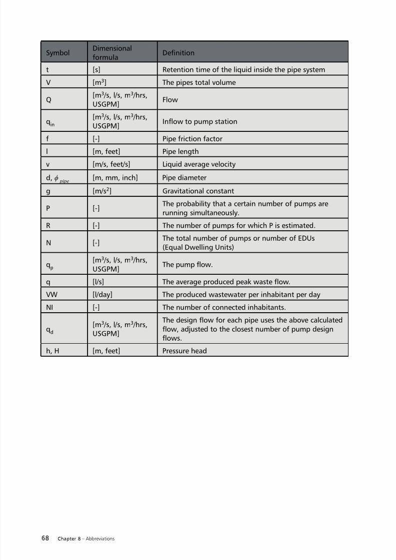
7/18/2019 Pumping Handbook
http://slidepdf.com/reader/full/pumping-handbook 76/80
68 Chapter 8 – Abbreviations
SymbolDimensionalformula
Definition
t [s] Retention time of the liquid inside the pipe system
V [m3] The pipes total volume
Q [m3
/s, l/s, m3
/hrs,USGPM] Flow
qin
[m3 /s, l/s, m3 /hrs,USGPM]
Inflow to pump station
f [-] Pipe friction factor
l [m, feet] Pipe length
v [m/s, feet/s] Liquid average velocity
d, ϕ pipe
[m, mm, inch] Pipe diameter
g [m/s2] Gravitational constant
P [-]The probability that a certain number of pumps arerunning simultaneously.
R [-] The number of pumps for which P is estimated.
N [-]The total number of pumps or number of EDUs(Equal Dwelling Units)
qp
[m3 /s, l/s, m3 /hrs,USGPM]
The pump flow.
q [l/s] The average produced peak waste flow.
VW [l/day] The produced wastewater per inhabitant per day
NI [-] The number of connected inhabitants.
qd
[m3 /s, l/s, m3 /hrs,USGPM]
The design flow for each pipe uses the above calculatedflow, adjusted to the closest number of pump designflows.
h, H [m, feet] Pressure head

7/18/2019 Pumping Handbook
http://slidepdf.com/reader/full/pumping-handbook 77/80
69Chapter 8 – Abbreviations

7/18/2019 Pumping Handbook
http://slidepdf.com/reader/full/pumping-handbook 78/80

7/18/2019 Pumping Handbook
http://slidepdf.com/reader/full/pumping-handbook 79/80

7/18/2019 Pumping Handbook
http://slidepdf.com/reader/full/pumping-handbook 80/80
ITT is a global provider of water handling and treatment solutions for municipal and industrial
customers in more than 140 countries. The company designs and delivers energy-efficient
solutions and related services for water and wastewater transport, biological treatment, filtra-
tion, and disinfection through five global brands – Flygt, Godwin Pumps, Leopold, Sanitaire
and Wedeco.
The company maintains the industry’s most extensive sales and service organization, operating
both locally and globally to meet the needs of customers. And by combining its world-classproducts and engineering expertise, ITT can offer integrated and multi-discipline solutions
including full process design, equipment selection and supply, installation, commissioning
and operator training.
To learn more, please visit the company’s website: http://www.ittwww.com/.
1 2 7 1 .
P S S H a n d
b o o k .
1 .
M a s t e r .
1 .
2 0 1 1 0 6 3 0