Embed Size (px)
Citation preview
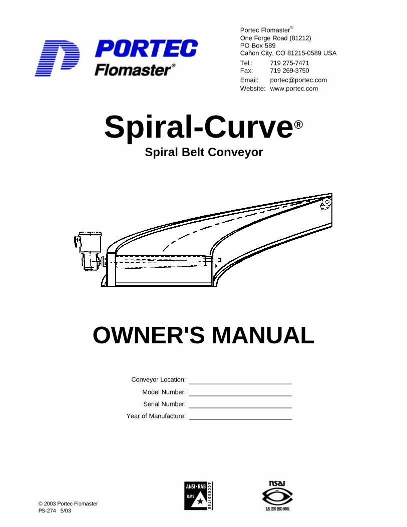
Spiral-Curve® Spiral Belt Conveyor
OWNER'S MANUAL
Conveyor Location:
Model Number:
Serial Number:
Year of Manufacture:
© 2003 Portec Flomaster PS-274 5/03
Portec Flomaster® One Forge Road (81212) PO Box 589 Cañon City, CO 81215-0589 USA
Tel.: 719 275-7471 Fax: 719 269-3750 Email: [email protected] Website: www.portec.com

TABLE OF CONTENTS
Page
Section I. Tool Requirements for Spiral-Curve Installation, Maintenance, & Belt Replacement ........................................................................................3
Section II. Preventive Maintenance ................................................................................4 A. Inspection & Service Schedule ...............................................................5 B. Inside Radius Belt Tension Adjustment Procedure .............................6 C. Belt Chain Tension Adjustment Procedure...........................................6 D. Belt Chain Sprocket Alignment Procedure ...........................................7 E. End Roll Alignment Procedure................................................................8 F. Lubrication ..................................................................................................9 G. Taper-Lock Bushings in End Rolls and Sprockets ............................ 10
Section III. Belt Replacement Procedure ..................................................................... 11
Section IV. Belt Attachment and Guides Replacement .............................................. 14 A. Belt Attachment-Link Replacement ..................................................... 14 B. Belt Chain Guide Replacement ........................................................... 16
Section V. Troubleshooting Guide................................................................................ 20
Section VI. Recommended Spare Parts List (RSPL) Spiral Curve .................................................................................................. 21
Section VII. Parts List – Spiral Curve ............................................................................. 22
Section VIII. Illustrated Parts Diagram – Spiral Curve .................................................. 24
Section IX. Warranty ....................................................................................................... 25
2

Section I Tool Maintenance for Spiral-Curve Installation,
Maintenance, and Belt Replacement
Tool Used For
10 mm & 15 mm Wrench Bearing Tensioners
15 mm Wrench or Socket Bearing Housing to Frame
1-3/16” (30 mm) dia shaft & smaller
18 mm Wrench or Socket Bearing Housing to Frame
1-7/16” (35 mm) dia shaft & larger
13 mm Wrench or Socket Chain Cover – Sideguards – End
Caps 13 mm Wrench or Socket Return Guide Extrusion to Frame
Socket Wrench Set with 3/8” drive and imperial and/or metric sockets Standard Drive Arrangements
Small Electric or Air Drill with 1/8” (3.2 mm) and 7/64" (2.8 mm) Drill Bits &
Hand Rivet Gun with 1/8” Steel Rivets Chain Guide Strips
5/32” Allen Wrench End Rolls 3/16” Allen Wrench Sprocket Set Screws
5/32” Allen Wrench Bearing to Shaft
1-7/16” (35 mm) dia. shaft & larger
1/8” Allen Wrench Bearing to Shaft
1-3/16” (30 mm) dia. shaft & smaller 3/32” Allen Wrench Return Wheels
Electricians Nut Driver Set Or Adjustable Wrench Electrical Motor Connections
Flat Blade (standard) Screw Driver Guide Material Pliers and Side Cutters Mechanical Lace Belt Splice
Grease gun Belt chain and End Roll Bearings Rubber Mallet or Small Pry Bar Belt Tension Adjustment
NOTE: Only trained personnel should perform all required work on the conveyor to prevent any danger to operators or other persons, and to prevent damage to the conveyor.
WARNING: Disconnect and lock-out power before performing any installation or maintenance procedures. All guards must be in place before startup of curve.
3

Section II Preventive Maintenance
Perform a complete conveyor inspection after the first 40 hours of operation.
• Check belt drive chain alignments to the sprockets and guides, and check the chain tension.
• Check drive components for alignment and check that all fasteners are secure.
A Portec Spiral-Curve may be provided with regreaseable bearings (4) at the drive and idler end rolls. Lubricate these bearings at the same time as other system conveyors, which are typically on a quarterly service interval.
Belt chain lubrication depending upon operating conditions.
Maintain the lubrication of the gearbox and drive chain (if equipped) according to the manufacturer’s recommendations.
Keep the area between the Spiral-Curve belt and bedplate relatively free from debris. Excessive debris may cause premature belt wear.
WARNING: Always disconnect the power and perform the appropriate lock-out/tag-out procedures before beginning service or maintenance on the conveyor.
4

A. Inspection & Service Schedule
Component(s) Service Internal
Task(s) Comments
Check belt chain alignment to sprockets and guides. Adjust position if required.
Check belt chain tension on unloaded side of sprocket.
To tighten chain, use jack bolt at outside radius.
Check belt condition. Observe overall condition for fraying, cuts, gouges, seams, etc.
Check drive components alignment/performance. Adjust if required.
Check that all fasteners and hardware are secure.
Tighten if required. Do not operate unless secure.
Curve Monthly
Check that all guards are securely in place and properly adjusted.
Readjust for clearances and secure.
Belt & Components
Quarterly Check for belt and seam damage. Check belt to chain attachments.
Repair or replace as needed.
Check end roll bearings for noise and lubrication.
Lubricate or replace as needed.
Check end roll alignment in relation to sprocket and chain guide. Adjust if required.
Check end roll assembly set screws to ensure they are tight.
Adjust/tighten if required.
Check that both end caps are non-damaged and properly adjusted.
Readjust for clearances and secure.
Check shafts for condition with no visible damage.
If shaft is damaged from spinning in loose bearing collar or sprocket, replace as needed.
End Roll Assemblies Quarterly
Check sprockets for tooth wear. Adjust or replace as needed.
Check drive sprockets/chain or belt for wear.
Replace as needed.
Check motor/reducer or gear motor for noise.
Adjust if required or replace as needed.
Check chain or belt tension. Adjust if required.
Drive Arrangement Quarterly
Check gear box lubrication level. Refer to manufacturer’s specifications.
Quarterly Grease upper chain guides. Interval depends upon conditions Chain Guides Semi-
Annually Check upper and lower chain guide strips for wear. Replace as needed.
Check return wheels for noise. Replace as needed.
Check to ensure that return wheels are in contact with belt.
Adjust if required. Return Wheels Semi- Annually
Check that return wheels turn freely when in contact with belt.
Replace as needed.
5
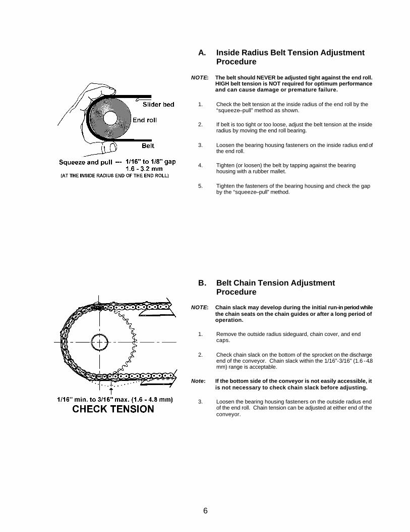
A. Inside Radius Belt Tension Adjustment Procedure
NOTE: The belt should NEVER be adjusted tight against the end roll. HIGH belt tension is NOT required for optimum performance and can cause damage or premature failure.
1. Check the belt tension at the inside radius of the end roll by the “squeeze–pull” method as shown.
2. If belt is too tight or too loose, adjust the belt tension at the inside radius by moving the end roll bearing.
3. Loosen the bearing housing fasteners on the inside radius end of the end roll.
4. Tighten (or loosen) the belt by tapping against the bearing housing with a rubber mallet.
5. Tighten the fasteners of the bearing housing and check the gap by the “squeeze–pull” method.
B. Belt Chain Tension Adjustment Procedure
NOTE: Chain slack may develop during the initial run-in period while the chain seats on the chain guides or after a long period of operation.
1. Remove the outside radius sideguard, chain cover, and end caps.
2. Check chain slack on the bottom of the sprocket on the discharge end of the conveyor. Chain slack within the 1/16”-3/16" (1.6 - 4.8 mm) range is acceptable.
Note: If the bottom side of the conveyor is not easily accessible, it is not necessary to check chain slack before adjusting.
3. Loosen the bearing housing fasteners on the outside radius end of the end roll. Chain tension can be adjusted at either end of the conveyor.
6

4. Use the jack bolt next to the bearing housing to move the end roll assembly. Move the outside radius end of the end roll assembly until the chain may be depressed 1/8" (3 mm) between the sprocket and the chain guide.
5. Tighten the backing nut used on the jack bolt and the bearing housing fasteners.
6. Check the alignment of the chain sprocket and the chain guides. If adjustment is necessary, see the Chain Sprocket Adjustment Procedures.
7. Replace the chain cover, end caps, and sideguard. Move the end caps close to the end roll without touching the conveyor belt.
D. Belt Chain Sprocket Alignment Procedure
NOTE: Chain “rattle” or “popping” as the chain engages or disengages the end roll sprocket may indicate that the sprockets need to be aligned.
1. Remove the outside radius sideguard, chain cover and end caps.
2. Check the condition of the sprocket teeth. Excessive uneven wear on the teeth indicate misalignment of the sprocket.
3. Check the alignment of the chain, sprocket, and chain guides. The sprocket should be centered in the chain path.
4. Loosen the set screws in the sprocket hub to loosen the sprocket on the shaft.
5. Move the sprocket to the correct position. As the conveyor is operating, you should be able to see light between the sprocket side and the chain on each side of the bottom of the sprocket.
6. Tighten set screws.
7. Test run the conveyor and listen for the rattle or popping noise.
8. Install chain cover, end caps, and sideguard. Move the end caps close to the end roll without touching the conveyor belt.
7

E. End Roll Alignment Procedure
NOTE: The Portec engineered tapered end roll permits the belt to travel radially accommodating the differences in belt speed from the inside radius to the outside radius without scuffing (wearing) the bottom side of the belt as is common with cylindrical end roll variations of other systems. End roll lagging IS NOT required because the belt is powered by the positive mechanical belt/chain drive and NOT by a friction drive dependent on high belt tension against the end pulley common to other systems.
1. Remove the outside radius sideguard, chain cover, and end caps.
2. Move the belt assembly until the laced belt seam with the chain connecting link is on top of the conveyor bed and near the end roll that requires adjustment.
3. Remove the chain connecting-link and clip, and the belt seam-lacing pin. Lay the belt back to expose the end roll.
4. Check the position of the end roll in relation to the upper chain guide.
5. Loosen the end roll set screws.
6. Slide the end roll on the shaft to the correct position and tighten the setscrews.
7. Loosen the bearing housing fasteners and raise (or lower) the end roll until the top of the end roll is at the same height as the slider bed. Tighten the bearing housing fasteners.
8. Install the chain-connecting link to reconnect the chain
8

NOTE: Install the connecting link clip on the outer side of the chain with the open end of the clip opposite the direction of belt travel.
9. Reinstall the lacing pin. Bend the lacing pin over on the outside radius and insert the end of the lacing pin into the lacing hooks. Ensure that at least 1/2" (13 mm) of lacing pin is inserted into the lacing hooks. Pull the lacing pin taut on the inside radius, bend the lacing pin back and insert the end of the lacing pin into the lacing hooks. The lacing pin may have to be cut to length so that about 1/2" (13 mm) of lacing pin is inserted into the lacing hooks. Crimp two or three lace hooks down on the end of the lacing pin at inside radius to hold the pin in place.
10. Replace the chain cover, end caps, and sideguard. Move the end caps close to the end roll without touching the conveyor belt.
F. Lubrication
The upper chain guides should be periodically lubricated. A mixture of dried grease and dust can greatly reduce the life of the chain and chain guides. This is especially true if the conveyor operates in dusty conditions. The conveyor is equipped with grease fittings located in the chain cover along the length of the chain. We recommend using Lubriplate Molith #2 grease. The frequency of lubrication and amount required will depend upon the load, speed, and environmental conditions. Some general guidelines are as follows:
Clean conditions @ 8 hours per day Lube every 3-4 months Clean conditions @ 18 hours per day Lube every 6-8 weeks
Dusty conditions @ 8 hours per day Lube every 4-6 weeks - Clean chain every 4-6 months
High humidity Lube enough to stop rust and every 4-5 weeks
WARNING: Running a conveyor that does not have adequate lubrication will damage the conveyor and substantially shorten the life of the chain. Periodic chain cleaning in solvent is highly recommended when operating in dusty conditions. After cleaning, apply new grease to the entire length of the chain and work it well into the moving parts.
All Spiral Curves have grease fittings in the chain cover. The number of grease fittings on your particular Spiral-Curve will depend upon size and arc.
Note: If the conveyor is operating in a food application, refer to the
appropriate government regulation for the correct type of food-grade grease.
9

G. Taper-Lock Bushings in End Rolls and Sprockets (if equipped)
1. Loosening taper lock bushings: Remove the set screws and insert one into the hole, which is threaded in the bushing only, using it as a jack screw. This will disengage the bushing for removal.
2. Tightening taper lock hubs: Insert both set screws in opposing half thread holes with the bushing hole pattern matching the hub pattern. Alternately tighten both set screws. Lightly tap the bushing to ensure proper seating and re-tighten both set screws.
Recommended Installation Wrench Torque
Bushing No. Lb. In. Nm 1610 175 19.9 2012 280 31.8
2517 430 48.8
10

Section III Belt Replacement Procedure
1. Disengage or remove the drive unit so the conveyor belt can move around the conveyor. A shaft-mount gear reducer will require complete removal. V-belt or chain/sprocket drive can be disengaged by removal of v-belt or chain.
2. Remove the outside radius sideguard, chain cover, and end caps. Move the conveyor belt until the chain-connecting link is on top of the conveyor bed.
3. Loosen the bearing housing fasteners on the end rolls. Loosen the jack bolts on the outside radius frame. Push the end roll assemblies to loosen the belt tension.
4. Remove the connecting-link and clip from the belt chain. Remove the seam-lacing pin from the conveyor belt.
5. Lay one end of the belt back from the opened seam to expose the conveyor bed. Put an 1/8" (3 mm) bead of Lubriplate Molith #2 grease in the groove of the upper chain guide. No other grease will be required for the life of the belt assembly.
Note: Conveyor applications with food products may require a food-grade grease.
11
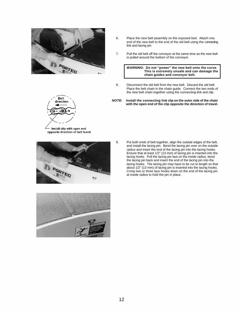
6. Place the new belt assembly on the exposed bed. Attach one end of the new belt to the end of the old belt using the connecting link and lacing pin
7. Pull the old belt off the conveyor at the same time as the new belt is pulled around the bottom of the conveyor.
WARNING: Do not “power” the new belt onto the curve. This is extremely unsafe and can damage the chain guides and conveyor belt.
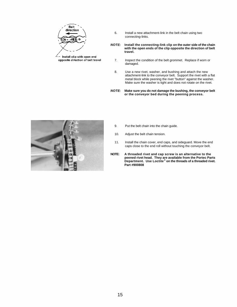
8. Disconnect the old belt from the new belt. Discard the old belt. Place the belt chain in the chain guide. Connect the two ends of the new belt chain together using the connecting-link and clip.
NOTE: Install the connecting link clip on the outer side of the chain with the open end of the clip opposite the direction of travel.
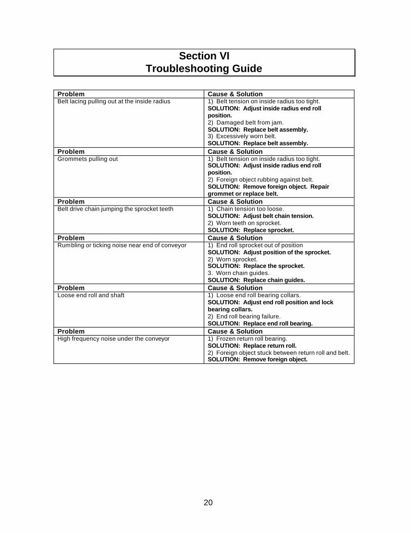
9. Put both ends of belt together, align the outside edges of the belt, and install the lacing pin. Bend the lacing pin over on the outside radius and insert the end of the lacing pin into the lacing hooks. Ensure that at least 1/2" (13 mm) of lacing pin is inserted into the lacing hooks. Pull the lacing pin taut on the inside radius, bend the lacing pin back and insert the end of the lacing pin into the lacing hooks. The lacing pin may have to be cut to length so that about 1/2" (13 mm) of lacing pin is inserted into the lacing hooks. Crimp two or three lace hooks down on the end of the lacing pin at inside radius to hold the pin in place.
12

10. Adjust the chain tension so that the chain can be depressed 1/8"
(3 mm) max. between the end roll sprocket and the chain guide. Use the jack bolt next to the bearing housing to move the end roll assembly. As you move the end roll assembly inward, the chain tension will be reduced. The end rolls at the inside radius should remain loose.
11. Tighten the backing nuts on the jack bolts and the bearing housing fasteners.
12. Check the alignment of the chain, sprockets, and chain guides.
13. Adjust the belt tension on the inside radius by moving the bearing housing of the end roll. Use a rubber mallet to move the bearing housing.
14. Tighten the bearing housing fasteners and recheck the gap between the end roll and belt by the “squeeze–pull” method.
15. Replace the chain cover, end-caps, and sideguard. Move the end caps close to the end roll without touching the conveyor belt.
16. Reengage or reinstall the drive unit. Install all safety guards and test run.
13

Section IV Belt Attachment Link and Chain Guide Replacement
• The belt attachment link is used to attach the belt chain to the belt along the outside radius. This provides a positive belt-driven system not attainable by other systems that use extreme belt tension of a friction drive.
A. Belt Attachment-Link Replacement
1. Remove the outside radius sideguard, chain cover and end caps.
2. Rotate the conveyor belt until the damaged attachment-link is on top of the conveyor bed.
3. Loosen the bearing housing fasteners on the outside radius at the non-drive end. Loosen the jack bolt and move the bearing assembly in to relieve the belt chain tension.
4. Lift the chain from the chain guide near the damaged attachment-link. Break the belt chain on each side of the damaged attachment-link.
5. Bend the edge of the conveyor belt over to expose the bottom. Grind off the rivet head that attaches the attachment-link to the conveyor belt. Remove the damaged attachment-link.
WARNING: Observe all appropriate safety precautions while using grinding tools to avoid personal injury.
NOTE: Do not contaminate the chain guides with metal particles or damage the conveyor belt while grinding.
14
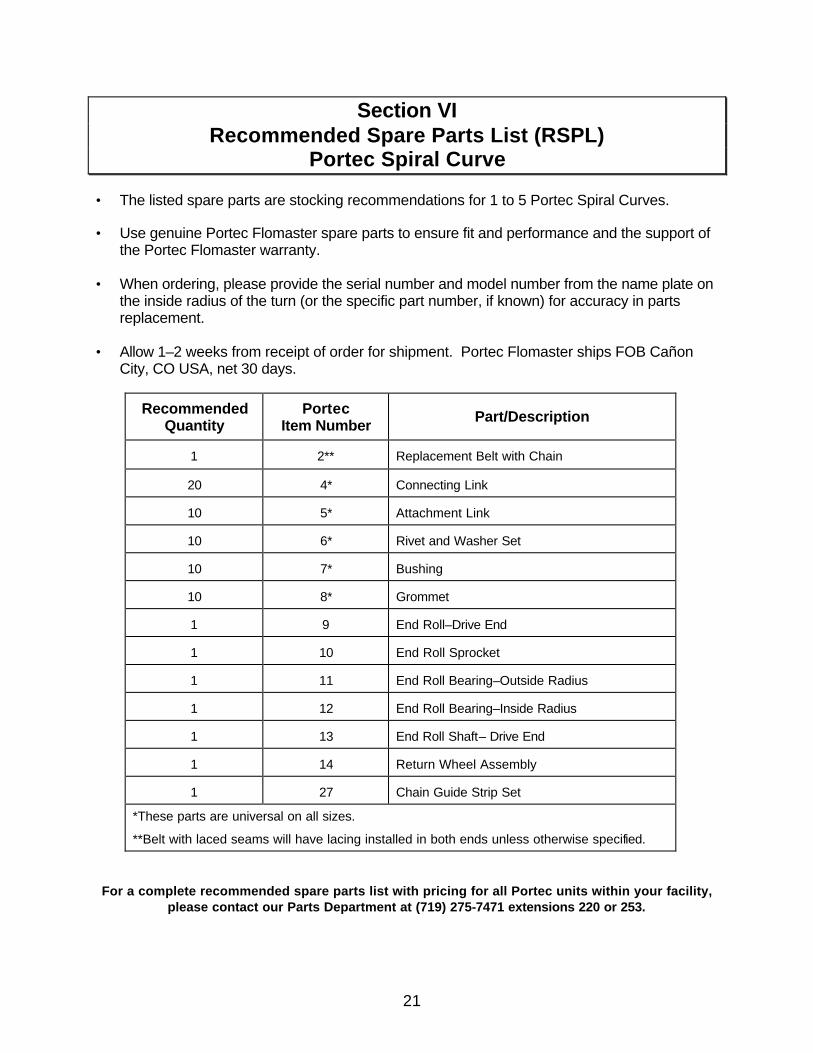
6. Install a new attachment-link in the belt chain using two
connecting-links.
NOTE: Install the connecting-link clip on the outer side of the chain with the open ends of the clip opposite the direction of belt travel.
7. Inspect the condition of the belt grommet. Replace if worn or damaged.
8. Use a new rivet, washer, and bushing and attach the new attachment-link to the conveyor belt. Support the rivet with a flat metal block while peening the rivet "button" against the washer. Make sure the washer is tight and does not rotate on the rivet.
NOTE: Make sure you do not damage the bushing, the conveyor belt or the conveyor bed during the peening process.
9. Put the belt chain into the chain guide.
10. Adjust the belt chain tension.
11. Install the chain cover, end caps, and sideguard. Move the end caps close to the end roll without touching the conveyor belt.
NOTE: A threaded rivet and cap screw is an alternative to the peened rivet head. They are available from the Portec Parts Department. Use Loctite ® on the threads of a threaded rivet. Part #900808
15

B. Belt Chain Guide Replacement
B1. Upper Chain Guide(s) Replacement:
1. Remove the outside radius sideguard, chain guard and end caps.
2. Move the connecting-link to the top of the conveyor bed. Remove the connecting-link and the belt lacing pin. Fold the conveyor belt back to expose the entire upper guide assembly.
3. Remove the end roll assembly on one end.
4. Follow the Chain Guide Installation steps on the following pages. There are two styles of return chain guide assemblies used in a Spiral Curve. The "G3" style uses an aluminum bracket to hold the chain guides. The "G2" style has welded steel brackets.
5. Reinstall the end roll assembly. 6. Reinstall the belt and chain assembly. 7. Lubricate the chain and reset the chain tension. 8. Check the position of the sprockets to ensure that they are in the
center of the chain path. 9. Replace the chain cover.
16

Chain Guide Installation for Spiral Curves with Aluminum Return
Chain Guide Brackets ("G3 Style")
17

15 18
Chain Guide Installation for Spiral Curves with Welded Steel
Return Chain Guide Brackets ("G2 Style")

B2. Return Guide(s) replacement:
1. Remove upper rows of fasteners along the lower side of the outside radius frame to disconnect the top return guide brackets. Slide the top return guide bracket out one end of the conveyor. The top return guide bracket with chain guide must be replaced as a unit.
2. Remove the 6–32 x 1/2” flat-head screws at both ends of the bottom return guides.
3. Slide the worn or damaged guide out of the guide bracket. 4. Slide the new guide(s) into the guide bracket(s) to the correct
position and install one 6–32 x 1/2” screw at each end.
5. Slightly bend the ends of the bottom guide and bracket down to ease the entry or exit of the chain.
6. Slide the top guide bracket into position under the conveyor. Install the fasteners and tighten. Put the belt chain in this assembly.
7. Reinstall the end roll assembly. 8. Reassemble the belt chain using the connecting-link and the belt
lacing pin.
9. Check the alignment of the belt chain and sprockets to the new chain guides. Adjust the sprocket position if necessary.
10. Replace chain cover and sideguard. Move the end caps close to the end roll without touching the conveyor belt.
19
Section VI Troubleshooting Guide
Problem Cause & Solution Belt lacing pulling out at the inside radius 1) Belt tension on inside radius too tight.
SOLUTION: Adjust inside radius end roll position. 2) Damaged belt from jam. SOLUTION: Replace belt assembly. 3) Excessively worn belt. SOLUTION: Replace belt assembly.
Problem Cause & Solution Grommets pulling out 1) Belt tension on inside radius too tight.
SOLUTION: Adjust inside radius end roll position. 2) Foreign object rubbing against belt. SOLUTION: Remove foreign object. Repair grommet or replace belt.
Problem Cause & Solution Belt drive chain jumping the sprocket teeth 1) Chain tension too loose.
SOLUTION: Adjust belt chain tension. 2) Worn teeth on sprocket. SOLUTION: Replace sprocket.
Problem Cause & Solution Rumbling or ticking noise near end of conveyor 1) End roll sprocket out of position
SOLUTION: Adjust position of the sprocket. 2) Worn sprocket. SOLUTION: Replace the sprocket. 3. Worn chain guides. SOLUTION: Replace chain guides.
Problem Cause & Solution Loose end roll and shaft 1) Loose end roll bearing collars.
SOLUTION: Adjust end roll position and lock bearing collars. 2) End roll bearing failure. SOLUTION: Replace end roll bearing.
Problem Cause & Solution High frequency noise under the conveyor 1) Frozen return roll bearing.
SOLUTION: Replace return roll. 2) Foreign object stuck between return roll and belt. SOLUTION: Remove foreign object.
20
Section VI Recommended Spare Parts List (RSPL)
Portec Spiral Curve • The listed spare parts are stocking recommendations for 1 to 5 Portec Spiral Curves.
• Use genuine Portec Flomaster spare parts to ensure fit and performance and the support of the Portec Flomaster warranty.
• When ordering, please provide the serial number and model number from the name plate on the inside radius of the turn (or the specific part number, if known) for accuracy in parts replacement.
• Allow 1–2 weeks from receipt of order for shipment. Portec Flomaster ships FOB Cañon City, CO USA, net 30 days.
Recommended Quantity
Portec Item Number Part/Description
1 2** Replacement Belt with Chain
20 4* Connecting Link
10 5* Attachment Link
10 6* Rivet and Washer Set
10 7* Bushing
10 8* Grommet
1 9 End Roll–Drive End
1 10 End Roll Sprocket
1 11 End Roll Bearing–Outside Radius
1 12 End Roll Bearing–Inside Radius
1 13 End Roll Shaft– Drive End
1 14 Return Wheel Assembly
1 27 Chain Guide Strip Set
*These parts are universal on all sizes.
**Belt with laced seams will have lacing installed in both ends unless otherwise specified.
For a complete recommended spare parts list with pricing for all Portec units within your facility, please contact our Parts Department at (719) 275-7471 extensions 220 or 253.
21

Section VII Parts List — Portec Spiral Curve
• Please supply the following information when ordering or corresponding with us regarding
replacement parts for your Spiral Curve: SERIAL NUMBER and MODEL NUMBER from the name plate on the curve, and PORTEC ITEM NUMBER corresponding to your requirement from the illustrated Parts Diagram. The Serial Number (or the specific part number, if known) will ensure an equivalent replacement. To obtain any part not listed or shown, please consult our Parts Department at (719) 275-7471 extensions 220 or 253.
Portec Item # Portec Part No. Part/Description
2** Curve Belt Assembly with Drive Chain – Complete assembly, ready for replacement
3CT 190129 Chain Breaker Tool – For breaking belt chain to replace attachment link
4* Std. – 020238 Nickel Plated –
020235
Connecting Link (#50) – For assembly of turn belt drive chain
5* Std. – 020229 Nickel Plated –
020230
Attachment Link (#50) – For attaching chain and belt. Two connecting links required with each attachment link.
6* Std. – 600347 S/S – 600854
Rivet and Washer Set – Assembly at link to belt attachment
7* 080020 Nylon Bushing – Use with item 6 rivet and washer assembly
8* Std. – 190100 Nickel Plated –
190101 Grommet – Install in belt to house items 6 & 7 assembly
8CT 190121 Installation Punch and Die Tool – for grommet replacement
9 End Roll – Tapered roll on each end of curve. No bearings or shafts included.
10 End Roll Sprocket – Beveled tooth
11 End Roll Bearing – Outside Radius
12 End Roll Bearing – Inside Radius
13 End Roll Shaft – Drive end with drive extension, keyway(s) and key(s)
14 Return Wheel Assembly – Includes shaft and wheel(s)
14a Return Wheel Shaft
14b Straight Return Roll - 7/16" hex bore
14c 010315 Return Wheel – Rubber tire bearing; 5/8" bore
17++ Bed Roll – Single with bearings
22

Portec Item # Portec Part No. Part/Description
19++ Bed Roll Shaft
24 End Roll Shaft – Non-Drive with keyway(s) and key(s)
25++ Sideguard – Outside Radius
26++ Sideguard – Inside Radius
27 Chain Guide Set – Complete set of upper and lower chain
guide strips with installation hardware and instructions
27a Upper Chain Guide Set – Chain guide strips with installation hardware and instructions
27b Top Return Chain Guide Assembly - Aluminum holder with chain guide strips installed; with installation hardware and instructions (G3 style only)
27c Bottom Return Chain Guide Assembly - Aluminum holder with chain guide strips installed; with installation hardware and instructions (G3 style only)
28 Belt Seam Lace Assembly – Belt lace hooks with pin
28BT 110007 Belt Lacing Tool – For field installation of belt seam lace;
for #1 hook
29 Chain Cover – Outside Radius
*These parts are universal on all sizes.
**Replacement belts with laced seams will have lacing installed in both ends unless otherwise specified.
++(Optional)
23

Section VIII Illustrated Parts Diagram — Portec Spiral Curve
24

Section IX Warranty
PORTEC FLOMASTER warrants the material and workmanship of its manufactured products, with exceptions noted below, for a period of 12 months beginning one month from the date of shipment from PORTEC FLOMASTER’S factory, according to recorded serial numbers.
Within the period noted above, any material or workmanship showing defects will be repaired or replaced, provided PORTEC FLOMASTER is given written notice within 30 days after failure, and a willingness is expressed to submit the product to PORTEC FLOMASTER, and if PORTEC FLOMASTER authorizes the return of the product, the product is returned. Warranty parts are supplied F.O.B. PORTEC FLOMASTER’S factory and unless express agreement is made by PORTEC FLOMASTER the purchaser shall bear expense of installation. PORTEC FLOMASTER reserves the right at any time to supervise or install any part of replacement, or supervise adjustment incident to satisfactory operation of equipment.
Unauthorized returns, modifications, additions or variations, from procedures and information contained in PORTEC FLOMASTER'S Owner’s Manuals, and Product Data Bulletins, or any misuse, negligence, accident, product jam, or loading beyond rated capacity invalidates this warranty.
Exceptions:
1. Because of varying operating conditions, all belting supplied will necessarily be subject to manufacturer’s warranty, rather than that of PORTEC FLOMASTER. *
2. In case of motor or reducer failure, please contact the nearest Authorized Representative of the manufacturer. This warranty is void if motor or reducer is tampered with or disassembled by someone other than the Authorized Representative. *
3. PORTEC FLOMASTER further reserves the right to void its warranty where final destination and specific application are withheld; product is improperly installed or maintained by others; product is improperly protected against hazards and adverse environmental conditions during storage prior to or during installation; and/or product is used for applications/conditions other than indicated upon placement of order.
* PORTEC FLOMASTER will assist in the handling of warranty claims with such manufacturers to the end that satisfactory performance may be obtained.
THE FOREGOING WARRANTY IS EXCLUSIVE AND IN LIEU OF ALL OTHER WARRANTIES WHETHER WRITTEN, ORAL, OR IMPLIED (INCLUDING ANY WARRANTY OF MERCHANTABILITY OR FITNESS FOR ANY PURPOSE). UNDER NO CIRCUMSTANCES SHALL PORTEC FLOMASTER BE LIABLE FOR INCIDENTAL OR CONSEQUENTIAL DAMAGES.
The foregoing warranty cannot be changed except by written authorization signed by an authorized PORTEC FLOMASTER representative, and no attempt to repair or promise to repair or improve PORTEC FLOMASTER PRODUCTS by any other representative of PORTEC FLOMASTER shall change or extend said warranty in any manner whatsoever.
25