Embed Size (px)
Citation preview

Preparing for Your New Metal BeltConveyor Alignment
Proper alignment is essential forconsistent belt tracking and longservice life.
The end rolls, snub rolls, and allsupport rolls must be level and parallel or else the belt becomes diffi cult to track and tends to stretch along one edge.
Tools Needed1. A surveyor’s transit2. Carpenter’s level3. Piano wire4. Chalk and chalk line5. 12 foot steel tape
Procedure
Use the carpenter’s level to level all rolls to an accuracy of + or –1/32”.
Position the rolls parallel to eachother and perpendicular to the con-veyor center line. All other rolls must then be adjusted parallel to these rolls.
For Long or Enclosed Conveyors
An outside center line must beestablished. This can be a fi nely drawn chalk line on the fl oor or a very taut length of piano wire. It should be far enough from the conveyor to allow focusing of the transit.
The outside center line is located by measuring dim. A from the centers of both end rolls. (If the end rolls have lathe turned edges, measure A from the edges of the roll rather than from the center.) To prevent an error from a skewed roll, A should be measured from both sides of each end roll. (Onturned edge rolls, compensate for width differences of the end rolls.)
Set up the transit in pos. 1. Accurately sight the transit on position 2 and rotate the transit 90 degrees to sight across the end roll.
Use this sighting and a plumb bobunder the transit to stretch a piano wire at the height of the roll center line. Use the carpenter’s level to level this wire. It is now perpendicular to the outside center line and parallel to the desired end roll position.
Position the end roll parallel to the cross wire by measuring and adjusting dim. C and D.
Next, stet up the transit in pos. 2 and sight on pos. 1. Swing the transit 90 degrees and set up a second cross wire. Follow the above procedure for E and F.
Now, both end rolls are aligned. These rolls should be securely bolted in place, pinned with dowel pins and punch marked to insure they are not moved.
To align the snub rolls to the end rolls, measure from the end rolls to the snub rolls. To avoid errors, measure directly from the end roll to the roll being aligned. Do not pin these rolls in place. In some cases, they are used to track the belt.
On new conveyors and/or when a new belt is being installed, all support rolls should be aligned parallel with the end drums before the belt is installed.
Rolls
All rolls should be checked for round-ness, free turn bearings, and run-outaccuracy as they rotate.
End rolls should not be crowned. If the drive roll is lagged, check it for wear. A modifi ed end-tapered roll may be used to assist in tracking.
The counter-tension roll should be resisted to uniform parallel motion. The take up system should operate as a single mechanism. Canting will stretch the belt edge and make tracking almost impossible.
Supports
All rails, skids, hearth plates andherringbone supports must be smooth, fl at and parallel with the end rolls. Sharp edges and abrupt corners should be removed since scraping will shorten the belt’s life.
Edge Guides
It is recommended that nothing touch the belt edge that might drag on the belt. But on applications where edge sensing is required, limit the force to one pound.
The conveyor is now ready for belt installation
Belt Installation
Do not attempt to install the belt without assuring that the conveyor alignment is correct.
Important: Remove the old belt and thread the pull-in cable through at the same time. This cable will be used for installation of the new belt later. Now, thoroughly clean the entire conveyor and be sure the belt path is clear. Correct any problems that caused damage to the previous belt.
Uncrate carefully. Avoid damaging the belt.
Direction of Travel Tag: and belt portions are tagged with a preferred direction of travel tag.Install the belt according to this preferred direction of travel. This indicates the direction in which the belt was tested.
Before Installation and againbefore applying tension to the belt, make sure that none of the spirals are turned up. They should be free to hinge about their proper axis.
During Installation use the pull-in cable attached to a yoke or lead in device to pull in the belt. This insures uniform tension across the full belt width. Be certain to pull the belt along the center of the conveyor evenly and avoid snagging the edges.
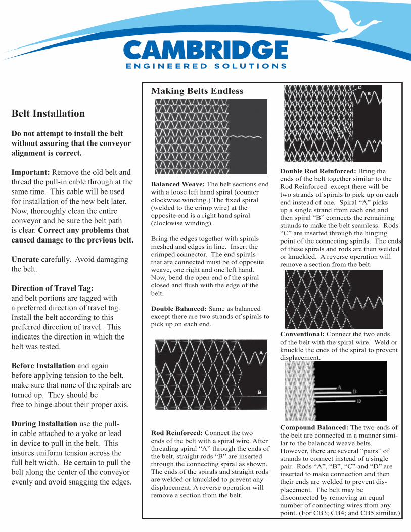
Making Belts Endless
Balanced Weave: The belt sections end with a loose left hand spiral (counter clockwise winding.) The fi xed spiral (welded to the crimp wire) at the opposite end is a right hand spiral (clockwise winding).
Bring the edges together with spirals meshed and edges in line. Insert the crimped connector. The end spirals that are connected must be of opposite weave, one right and one left hand.Now, bend the open end of the spiral closed and fl ush with the edge of the belt.
Double Balanced: Same as balanced except there are two strands of spirals to pick up on each end.
Rod Reinforced: Connect the two ends of the belt with a spiral wire. After threading spiral “A” through the ends of the belt, straight rods “B” are inserted through the connecting spiral as shown.The ends of the spirals and straight rods are welded or knuckled to prevent any displacement. A reverse operation will remove a section from the belt.
Double Rod Reinforced: Bring the ends of the belt together similar to the Rod Reinforced except there will be two strands of spirals to pick up on each end instead of one. Spiral “A” picks up a single strand from each end and then spiral “B” connects the remaining strands to make the belt seamless. Rods “C” are inserted through the hinging point of the connecting spirals. The ends of these spirals and rods are then welded or knuckled. A reverse operation will remove a section from the belt.
Conventional: Connect the two ends of the belt with the spiral wire. Weld or knuckle the ends of the spiral to prevent displacement.
Compound Balanced: The two ends of the belt are connected in a manner simi-lar to the balanced weave belts.However, there are several “pairs” of strands to connect instead of a single pair. Rods “A”, “B”, “C” and “D” are inserted to make connection and then their ends are welded to prevent dis-placement. The belt may be disconnected by removing an equal number of connecting wires from any point. (For CB3; CB4; and CB5 similar.)
TrackingA new belt will not normally track the same as the old belt did. Therefore, do not assume that tracking adjustments are not needed.
Each belt is tracked before it leaves the plant. It is then tagged to show its preferred direction of travel. Some belts can travel in either direction but the arrow shows the direction in which the belt was tested.
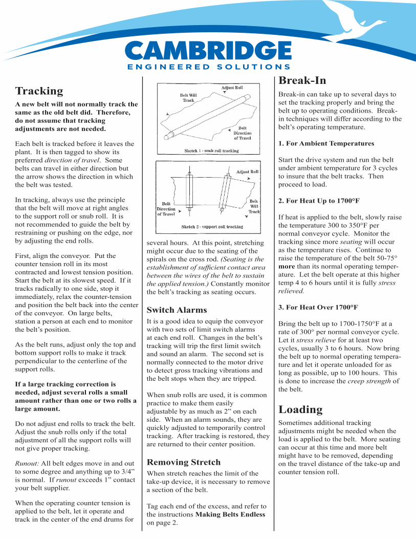
In tracking, always use the principle that the belt will move at right angles to the support roll or snub roll. It is not recommended to guide the belt by restraining or pushing on the edge, nor by adjusting the end rolls.
First, align the conveyor. Put the counter tension roll in its most contracted and lowest tension position.Start the belt at its slowest speed. If it tracks radically to one side, stop it immediately, relax the counter-tension and position the belt back into the center of the conveyor. On large belts, station a person at each end to monitor the belt’s position.
As the belt runs, adjust only the top and bottom support rolls to make it track perpendicular to the centerline of the support rolls.
If a large tracking correction is needed, adjust several rolls a small amount rather than one or two rolls a large amount.
Do not adjust end rolls to track the belt. Adjust the snub rolls only if the total adjustment of all the support rolls will not give proper tracking.
Runout: All belt edges move in and out to some degree and anything up to 3/4” is normal. If runout exceeds 1” contact your belt supplier.
When the operating counter tension is applied to the belt, let it operate and track in the center of the end drums for
several hours. At this point, stretching might occur due to the seating of the spirals on the cross rod. (Seating is the establishment of suffi cient contact area between the wires of the belt to sustain the applied tension.) Constantly monitor the belt’s tracking as seating occurs.
Switch AlarmsIt is a good idea to equip the conveyor with two sets of limit switch alarms at each end roll. Changes in the belt’s tracking will trip the fi rst limit switch and sound an alarm. The second set is normally connected to the motor drive to detect gross tracking vibrations and the belt stops when they are tripped.
When snub rolls are used, it is common practice to make them easilyadjustable by as much as 2” on each side. When an alarm sounds, they are quickly adjusted to temporarily control tracking. After tracking is restored, they are returned to their center position.
Removing StretchWhen stretch reaches the limit of the take-up device, it is necessary to remove a section of the belt.
Tag each end of the excess, and refer to the instructions Making Belts Endlesson page 2.
Break-InBreak-in can take up to several days to set the tracking properly and bring the belt up to operating conditions. Break-in techniques will differ according to the belt’s operating temperature.
1. For Ambient Temperatures
Start the drive system and run the belt under ambient temperature for 3 cycles to insure that the belt tracks. Then proceed to load.
2. For Heat Up to 1700°F
If heat is applied to the belt, slowly raise the temperature 300 to 350°F per normal conveyor cycle. Monitor the tracking since more seating will occur as the temperature rises. Continue to raise the temperature of the belt 50-75° more than its normal operating temper-ature. Let the belt operate at this higher temp 4 to 6 hours until it is fully stress relieved.
3. For Heat Over 1700°F
Bring the belt up to 1700-1750°F at a rate of 300° per normal conveyor cycle. Let it stress relieve for at least two cycles, usually 3 to 6 hours. Now bring the belt up to normal operating tempera-ture and let it operate unloaded for as long as possible, up to 100 hours. This is done to increase the creep strength of the belt.
LoadingSometimes additional tracking adjustments might be needed when the load is applied to the belt. More seating can occur at this time and more belt might have to be removed, depending on the travel distance of the take-up and counter tension roll.

Belt Warning SignalsConsider the belt as the barometer of the conveyor’s health. If there are anyconveyor problems, the belt is usually the fi rst to send out warning signals.
Most problems are easily solved. However, if the solutions below do not correct your problems, or if your problems are something other than listed, call your belt supplier.
Belt Jerking
1. Belt is not tracking well and is hanging somewhere along its edge.Correct by adjusting support rolls and snub rolls. Do not cant end rolls. They should be level and parallel at all times.
2. When there is a press roll drive and the belt is intermittently driving and slipping: Not enough press roll pressure. Be sure the press roll center line is parallel to the drive center line.
3. Take-up roll is stuck. The rollbearings are worn out and the roll is causing the belt to stop and go. Replace bearings.
4. Take-up roll is at the end of its travel.Check that the take-up roll is operating correctly or remove a section of the belt.
Belt Vibrations
1. Belt spirals pass over rough or un-even supports and vibration is induced.Support bed must be smooth and level or else excessive belt wear can occur.
2. Belt is dragging over some obstruc-tion, anglem channel, etc. Look over recent repair areas and check the conveyor frame for distortion, sagging and warpage.
3. Belt spirals bump as the belt goes around the end drums. Oval spirals are prone to this. Consider larger rolls and a longer pitch spiral weave. If severe, consider a belt with spirals of different lengths. Or, use a fl at spiral belt such as our OBFS or Flat Seat® belts.
4. Belt is pulsing in between bottomsupport rolls, causing vibration through-out the belt. Increase or decrease the take-up tension. This sometimes cures the vibration. Check the bearings. Add additional rolls, consider using a smooth surface belt such as OBFS or Flat Seat®.
Stretching
1. Overloading or overheating. Check with the belt manufacturer for recommended loads and temperatures plus the best belt alloy for the job.
2. Excessive take-up tension. Use only .daol eht gnivird erusni ot noisnet hguone
This is a common cause of belt stretch.
3. Oval spirals fl atten with time and cause progressive stretching. A 30 count belt which stretches .002” per spiral over 200 feet gives 12 inches of stretch. In some cases oval spirals fl atten and elongate 5 to 10 times this amount.Use our trademarked Flat Seat belts.They have fl at, thin spirals with longer pitch. Longer pitch belts reduce stretch-ing and are less expensive. The deep crimped cross rods of the Flat Seat® belts reduce cross rod elongation stretch.
4. On press roll driven conveyors, the press roll is set too tight and forcibly fl attens the spirals. If the spirals appear concave, suspect this condition. Use only enough press roll pressure to insure driving. Excess pressure is very damaging to a wire belt. Because of their high rounded shape, oval spirals are more easily deformed than the fl at, thin spirals of Flat Seat® belting.
Tracking
1. Runout. All belts have it. It’s when the belt edge runs back and forth slightly on the end drums. It’s related to slight variations within the wire itself and in most cases will not exceed 3/4”. Allow for it by using rolls and supports at least 2” to 4” wider than the belt.
2. The belt continuously drifts to one side of the unit. Correct this by adjusting the support rolls and snub rolls adjacent to the end drums. Do not cant end rolls.
3. Normally, each belt tracks differentlyand adjustments are needed when a new belt is put on. Install limit switches to signal rapid changes in tracking caused by roll shifting, product jamming, or other problems.
Distortion
1. Camber is distortion across the belt’s width. Its causes are many and complex. It is very damaging to a belt and every effort should be made to minimize it. For help, send a full width sample section along with a complete process and unit description to your belt supplier.
2. Camber can be caused by mechani-cal action and can be very severe. A belt constantly dragging along one edge will distort and break up. Rough support areas that cause extra friction can cause severe camber, wearing down of spirals, and uneven press roll driving.Longitudinal belt support beams can cause streaks, wear and camber.
3. Uneven heating and cooling across the belt. Maintain a temperature gradient of less than 25°F across the belt. Heat must be uniformly applied and radiant pot-type burners are discouraged. If the center of the belt is pulling ahead, look for drafts of cool air along the sides of the unit. Localized, highly oxidized strip areas down the length of the belt indicate and over-heated area.
Marking
The oval spirals of ordinary belts cause high indentation pressure. Our trademarked Flat Seat belt has a fl at spiral that gives a full base support to the product with less pounds per square inch of indentation pressure.
Cambridge Engineered Solutions
Cambridge, MD 21613Tel: 410-901-2660Toll Free: 877-815-3717Fax: 410-901-2680Toll Free Fax: 800-884-2723Web: www.cambridge-es.comEmail: [email protected] 3/09
105 Goodwill Rd.