Embed Size (px)
Citation preview

MICHIGAN STATE UNIVERSITY COLLEGE OF ENGINEERING ECE 480 – DESIGN TEAM 6
Programming the HEF4794B Shift Register Using Arduino
Application Note
Kristen Kirchhoff
4/5/2013
This application note is a guide on how to program a HEF4794B shift register using the Arduino Leonardo board and Arduino language.
Keywords: Shift register, HEF4794B, Arduino Leonardo, LEDs

1 | P a g e
Table of Contents 1. Introduction ................................................................................................................. 2
2. Components ................................................................................................................. 3
2.1 Hardware ................................................................................................................... 3
2.2 Software .................................................................................................................... 3
3. Procedure ..................................................................................................................... 3
3.1 The Circuit ................................................................................................................ 3
3.2 The Code ................................................................................................................... 5
3.3 Circuit and Code Implementation ........................................................................... 10
4.0 Project Applications .................................................................................................... 10
5.0 Conclusion .................................................................................................................. 11
6.0 References ................................................................................................................... 11
2 | P a g e
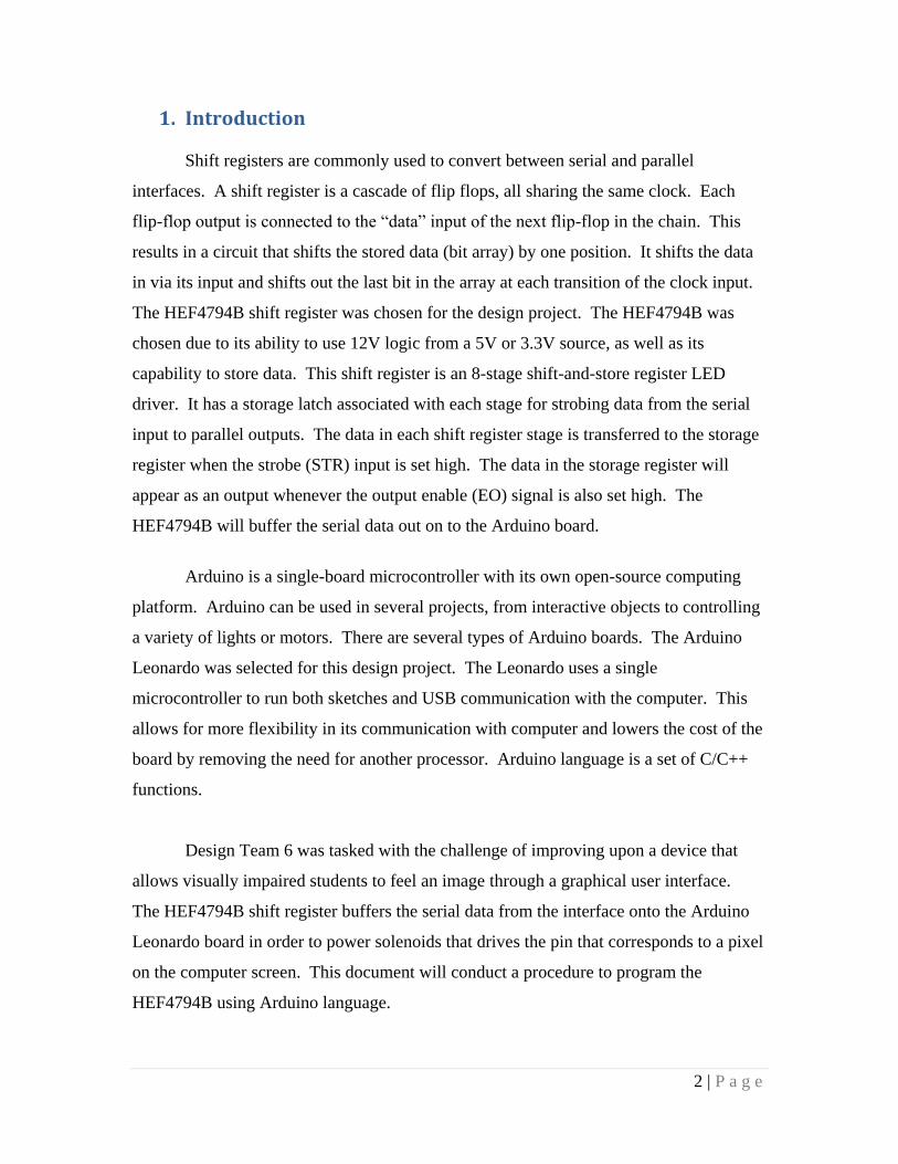
1. Introduction
Shift registers are commonly used to convert between serial and parallel
interfaces. A shift register is a cascade of flip flops, all sharing the same clock. Each
flip-flop output is connected to the “data” input of the next flip-flop in the chain. This
results in a circuit that shifts the stored data (bit array) by one position. It shifts the data
in via its input and shifts out the last bit in the array at each transition of the clock input.
The HEF4794B shift register was chosen for the design project. The HEF4794B was
chosen due to its ability to use 12V logic from a 5V or 3.3V source, as well as its
capability to store data. This shift register is an 8-stage shift-and-store register LED
driver. It has a storage latch associated with each stage for strobing data from the serial
input to parallel outputs. The data in each shift register stage is transferred to the storage
register when the strobe (STR) input is set high. The data in the storage register will
appear as an output whenever the output enable (EO) signal is also set high. The
HEF4794B will buffer the serial data out on to the Arduino board.
Arduino is a single-board microcontroller with its own open-source computing
platform. Arduino can be used in several projects, from interactive objects to controlling
a variety of lights or motors. There are several types of Arduino boards. The Arduino
Leonardo was selected for this design project. The Leonardo uses a single
microcontroller to run both sketches and USB communication with the computer. This
allows for more flexibility in its communication with computer and lowers the cost of the
board by removing the need for another processor. Arduino language is a set of C/C++
functions.
Design Team 6 was tasked with the challenge of improving upon a device that
allows visually impaired students to feel an image through a graphical user interface.
The HEF4794B shift register buffers the serial data from the interface onto the Arduino
Leonardo board in order to power solenoids that drives the pin that corresponds to a pixel
on the computer screen. This document will conduct a procedure to program the
HEF4794B using Arduino language.

3 | P a g e
2. Components
2.1 Hardware Personal Computer
Arduino Leonardo
Serial interconnect (USB)
HEF4794B
8 LEDs
8 resistors (270Ω)
2.2 Software Arduino IDE
Arduino Leonardo Drivers
3. Procedure
3.1 The Circuit
To begin wiring the HEF4794B chip, pin eight (GND) should be wired to
ground and pin 16 (Vcc) should be wired to supply voltage. This will deliver
power to the chip. The supply voltage is from the Arduino and will be 5V.
Figure 3.1-1 demonstrates these wired connections.
Figure 3.1-1: Schematic with supply voltage and ground connections made
4 | P a g e
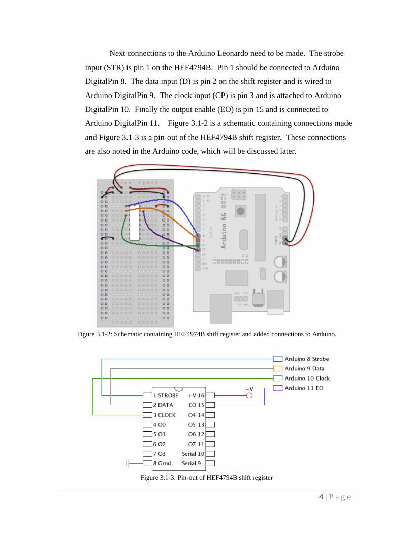
Next connections to the Arduino Leonardo need to be made. The strobe
input (STR) is pin 1 on the HEF4794B. Pin 1 should be connected to Arduino
DigitalPin 8. The data input (D) is pin 2 on the shift register and is wired to
Arduino DigitalPin 9. The clock input (CP) is pin 3 and is attached to Arduino
DigitalPin 10. Finally the output enable (EO) is pin 15 and is connected to
Arduino DigitalPin 11. Figure 3.1-2 is a schematic containing connections made
and Figure 3.1-3 is a pin-out of the HEF4794B shift register. These connections
are also noted in the Arduino code, which will be discussed later.
Figure 3.1-2: Schematic containing HEF4974B shift register and added connections to Arduino.
Figure 3.1-3: Pin-out of HEF4794B shift register
5 | P a g e
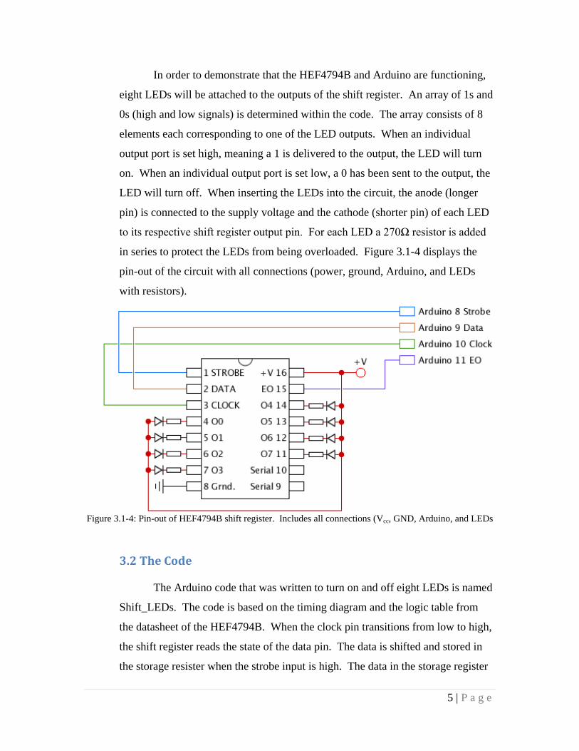
In order to demonstrate that the HEF4794B and Arduino are functioning,
eight LEDs will be attached to the outputs of the shift register. An array of 1s and
0s (high and low signals) is determined within the code. The array consists of 8
elements each corresponding to one of the LED outputs. When an individual
output port is set high, meaning a 1 is delivered to the output, the LED will turn
on. When an individual output port is set low, a 0 has been sent to the output, the
LED will turn off. When inserting the LEDs into the circuit, the anode (longer
pin) is connected to the supply voltage and the cathode (shorter pin) of each LED
to its respective shift register output pin. For each LED a 270Ω resistor is added
in series to protect the LEDs from being overloaded. Figure 3.1-4 displays the
pin-out of the circuit with all connections (power, ground, Arduino, and LEDs
with resistors).
Figure 3.1-4: Pin-out of HEF4794B shift register. Includes all connections (Vcc, GND, Arduino, and LEDs
3.2 The Code
The Arduino code that was written to turn on and off eight LEDs is named
Shift_LEDs. The code is based on the timing diagram and the logic table from
the datasheet of the HEF4794B. When the clock pin transitions from low to high,
the shift register reads the state of the data pin. The data is shifted and stored in
the storage resister when the strobe input is high. The data in the storage register

6 | P a g e
appears at the outputs whenever the output enable (EO) signal is high. To fully
understand when the shift register reads the state of the data pin, Figure 3.2-1
illustrates the timing diagram of the HEF4794B shift register. Table 3.2-1 is the
logic table, where functions are stated when any input pin is set high or low.
Figure 3.2-1: Timing diagram
INPUTS PARALLEL
OUTPUTS
SERIAL
OUTPUTS
CP EO STR D O0 On OS OS’
↑ L X X Z Z O6’ nc
↓ L X X Z Z nc O7
↑ H L X nc nc O6’ nc
↑ H H L L On - 1 O6’ nc
↑ H H H H On - 1 O6’ nc
↓ H H H nc nc nc O7
Table 3.2-1: Logic table
Key:
H = HIGH state ↑ = positive-going transition nc = no change
L = LOW state ↓ = negative-going transition O6’ = the information in the seventh shift register stage
X = don’t care Z = high-impedance OFF state
**at the positive clock edge the information in the 7th register stage is transferred to the 8th register stage and
the OS output
7 | P a g e
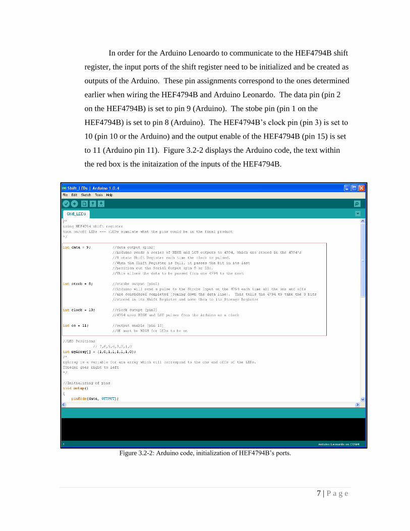
In order for the Arduino Lenoardo to communicate to the HEF4794B shift
register, the input ports of the shift register need to be initialized and be created as
outputs of the Arduino. These pin assignments correspond to the ones determined
earlier when wiring the HEF4794B and Arduino Leonardo. The data pin (pin 2
on the HEF4794B) is set to pin 9 (Arduino). The stobe pin (pin 1 on the
HEF4794B) is set to pin 8 (Arduino). The HEF4794B’s clock pin (pin 3) is set to
10 (pin 10 or the Arduino) and the output enable of the HEF4794B (pin 15) is set
to 11 (Arduino pin 11). Figure 3.2-2 displays the Arduino code, the text within
the red box is the initaization of the inputs of the HEF4794B.
Figure 3.2-2: Arduino code, initialization of HEF4794B’s ports.

8 | P a g e
In order to turn the LEDs on and off, an array of 1s and 0s was
established. The length of the array is eight, since there are eight LED outputs.
Each term in the array represents a LED position. For instance there are eight
output ports on the HEF4794B shift register. Therefore, the array assigns each
output port (O7 through O0) with a bit. If the bit passed to the port is a 1, then the
LED will turn on. If it is a zero, then the LED will turn off. Next, the pins must
be initialized. This authorizes the data pin, strobe pin, clock pin, and output
enable pin to be outputs. A function to pulse the clock must also be written. The
function will send a low, then high, then low pulse to the HEF4794B. This will
tell is to take a single bit (either a 1 or 0) from the array above. The HEF4794B
looks for the front of the pulse when it goes from low to high. It then accepts the
low or high input from the data pin into the shift register. The code within the red
box in Figure 3.2-3 exhibits these actions.
Figure 3.2-3: Arduino code, initialize LED positions, pins, and create clock function.
9 | P a g e
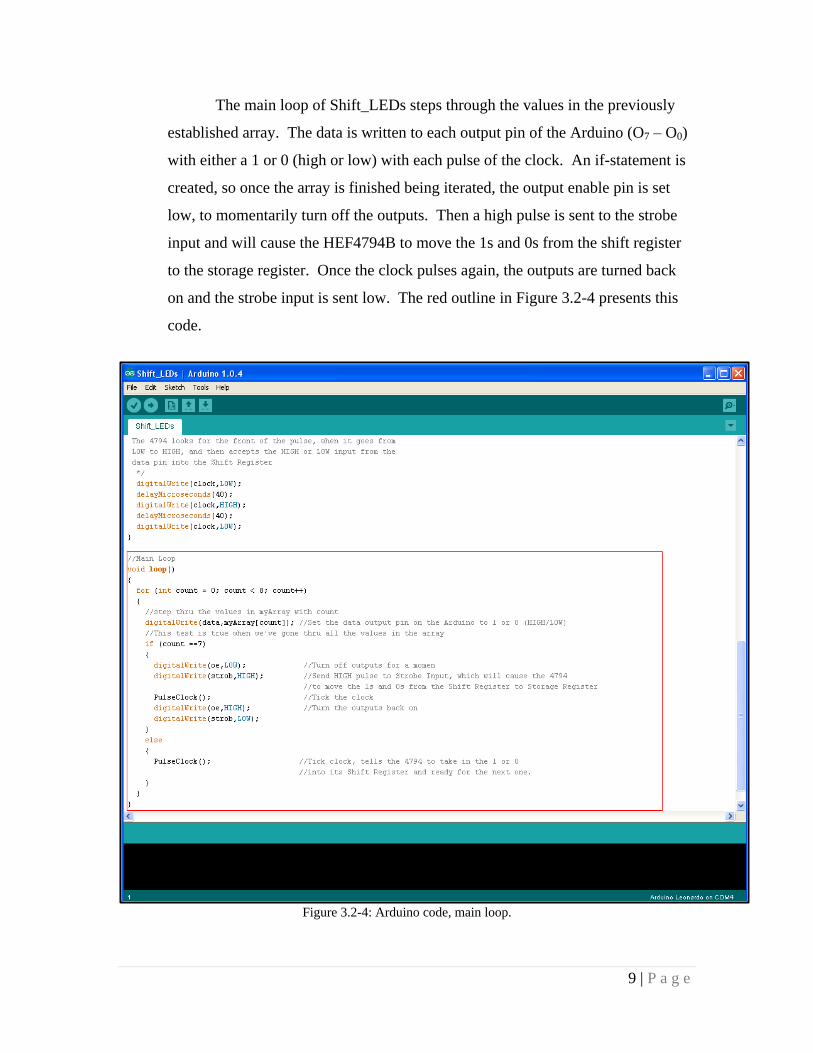
The main loop of Shift_LEDs steps through the values in the previously
established array. The data is written to each output pin of the Arduino (O7 – O0)
with either a 1 or 0 (high or low) with each pulse of the clock. An if-statement is
created, so once the array is finished being iterated, the output enable pin is set
low, to momentarily turn off the outputs. Then a high pulse is sent to the strobe
input and will cause the HEF4794B to move the 1s and 0s from the shift register
to the storage register. Once the clock pulses again, the outputs are turned back
on and the strobe input is sent low. The red outline in Figure 3.2-4 presents this
code.
Figure 3.2-4: Arduino code, main loop.
10 | P a g e
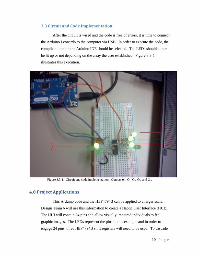
3.3 Circuit and Code Implementation
After the circuit is wired and the code is free of errors, it is time to connect
the Arduino Leonardo to the computer via USB. In order to execute the code, the
compile button on the Arduino IDE should be selected. The LEDs should either
be lit up or not depending on the array the user established. Figure 3.3-1
illustrates this execution.
Figure 3.3-1: Circuit and code implementation. Outputs on: O7, O6, O4, and O2.
4.0 Project Applications
This Arduino code and the HEF4794B can be applied to a larger scale.
Design Team 6 will use this information to create a Haptic User Interface (HUI).
The HUI will contain 24 pins and allow visually impaired individuals to feel
graphic images. The LEDs represent the pins in this example and in order to
engage 24 pins, three HEF4794B shift registers will need to be used. To cascade

11 | P a g e
the shift registers, the serial output pin (either pin 10 or 9 on the HEF4794B) will
need to be wired to the next register’s data pin (pin 2).
5.0 Conclusion
This application note introduced and gave a concise background of shift registers,
more specifically the HEF4794B, and the Arduino Leonardo board. A step-by-step
approach on how to program the HEF4794B using Arduino language was outlined. Shift
registers and the Arduino have several functional uses and can be used for almost any
project. This application note can assist in the implementation of other applications as
well as the creation of the HUI for this semester’s design project.
6.0 References
http://www.khazar.com/academics/portal/ucsc/2010winter/art22/class27.php
http://arduino.cc/en/Tutorial/ShiftOut
http://www.arduino.cc/en/Guide/Introduction
http://html.alldatasheet.net/html-pdf/17782/PHILIPS/HEF4794B/247/1/HEF4794B.html