Embed Size (px)
Citation preview

Product Catalog
March 2011
AquaStream 3G™
Air-Cooled Liquid Reversible Heat Pumps
Model CXAM
CG-PRC023-E4

© 2011 Trane All rights reserved CG-PRC023-E4
Introduction
Design and manufacturing excellence makes Trane a leader in the air-cooled chiller marketplace.
This tradition of using excellence to meet market demands is illustrated with the new Trane
AquaStream 3G the 55-450 kW air-cooled cooling unit. The introduction of this next-generation
chiller is an exciting step forward in energy-efficiency, sound, reliability, ease of serviceability,
control precision, application versatility, and operational cost-effectiveness. The new chiller is
designed to deliver proven AquaStream 3G performance based on the redesign of a European
model that has been a market leader, plus all the benefits of new heat transfer and fan designs, as
well as, low-speed, direct-drive scroll compressors.
Important Design Advances and New Features
• Higher full-load and part-load energy efficiency that reduce operating costs.
• Significantly lower noise levels than other scroll compressor chillers.
• HFC-410A optimized design.
• Factory-installed evaporator pump and buffer tank available to make installation easier.
• Flow switch and water strainer are factory installed in the optimum locations for seamless
operation and reduced chiller installation and maintenance time.
• Trane CH530™ with Adaptive Controls™ have improved fan algorithms for more reliable
operation at extreme conditions.
• Single chiller time of day scheduling communication for easier control of small jobs.
• Easily integrated with existing BAS via BACnet™, Modbus™, or LonTalk™ communication
interface.
• All major service components are close to the unit edge for safe and easy maintenance.
• The chiller is designed for easy serviceability with input from our extended experience in
design, testing and field operation.

Table of Contents
CG-PRC023-E4 3
Features and Benefits . . . . . . . . . . . . . . . . . . . . . . . . . . . . . . . . . . . . . . . . . . . . . . . . . . . 4
Application Considerations . . . . . . . . . . . . . . . . . . . . . . . . . . . . . . . . . . . . . . . . . . . . . . 7
Model Number Descriptions . . . . . . . . . . . . . . . . . . . . . . . . . . . . . . . . . . . . . . . . . . . . 16
General Data . . . . . . . . . . . . . . . . . . . . . . . . . . . . . . . . . . . . . . . . . . . . . . . . . . . . . . . . . . 18
Controls . . . . . . . . . . . . . . . . . . . . . . . . . . . . . . . . . . . . . . . . . . . . . . . . . . . . . . . . . . . . . . 54
Dimensions . . . . . . . . . . . . . . . . . . . . . . . . . . . . . . . . . . . . . . . . . . . . . . . . . . . . . . . . . . . 60
Mechanical Specifications . . . . . . . . . . . . . . . . . . . . . . . . . . . . . . . . . . . . . . . . . . . . . . 67
Options . . . . . . . . . . . . . . . . . . . . . . . . . . . . . . . . . . . . . . . . . . . . . . . . . . . . . . . . . . . . . . . 70
Hydraulic Data . . . . . . . . . . . . . . . . . . . . . . . . . . . . . . . . . . . . . . . . . . . . . . . . . . . . . . . . 75
Operating Map . . . . . . . . . . . . . . . . . . . . . . . . . . . . . . . . . . . . . . . . . . . . . . . . . . . . . . . . 79
Unit Schematics . . . . . . . . . . . . . . . . . . . . . . . . . . . . . . . . . . . . . . . . . . . . . . . . . . . . . . . 81

4 CG-PRC023-E4
Features and Benefits
Reliability
• Years of laboratory testing including running the chiller at extreme operating conditions have
resulted in optimized compressor and chiller systems reliability by confirming a robust design
and verifying quality each step of the way.
• Direct-drive, low-speed scroll compressors with fewer moving parts provide maximum
efficiency, high reliability, and low maintenance requirements. Suction gas-cooled motor stays
at a uniformly low temperature for long motor life.
• The third generation microprocessor control system provides improved control capabilities
with Adaptive Control™ to keep the unit operating even in adverse conditions. Advanced
microelectronics protect both the compressor and the motor from typical electrical fault
conditions like thermal overload and phase rotation.
• Flow switch is factory-installed at the optimum location in the piping for reduced chiller
installation cost and superior flow sensing, reducing the potential for nuisance trips.
• Exceptionally rigid condenser coil structure is designed with finished element analysis.
• Innovative condenser pressure integrated fan control algorithms provide more reliable
operation at extreme temperature conditions.
• Systematic factory run test prior to shipment.
Efficient, econonomical and environmentally friendly operation
• Industry leading full- and part-load efficiency in both cooling and heating mode, providing
economical operation and reduced CO2 emissions.
• Electronic expansion valve and high speed suction temperature sensor enables tight chilled
water temperature control and low superheat, resulting in more efficient full-load and part-load
operation than previously available.
• Optional water pumps inverter to adjust pump speed/waterflow rate and achieve all year round
savings.
• 410a refrigerant: a chlorine-free refrigerant with no negative impact on the ozone layer.
• Refrigerant leakage reduced thanks to high rigidity frame, brazed refrigerant connections,
extensive pressure and leakage testing all along the production process

CG-PRC023-E4 5
Features and Benefits
Application Versatility
• All year round operation: cooling capability from -18°C ambient up to 52°C with leaving water
down to -12°C. Heating capability down to -10°C ambient and leaving water temperature up to
55°C.
• Industrial/low temperature process cooling - Excellent operating temperature range and
precise control capabilities enable tight control.
• Ice/thermal storage - Utilities and owners benefit from reduced cooling energy cost. The
AquaStream 3G chiller’s dual setpoint control and industry leading ice energy storage
efficiency assures reliable operation and superior system efficiency.
• The factory-installed and tested pump package available with many options to meet a variety
of customer needs.
Simple, Economical Installation
• There is a variety of sound options to help meet many different job site requirements: compact,
super quiet and comprehensive acoustic package.
• System integration available with LonTalk, or ModBus, or BACnet through a single twisted-pair
wire for a less expensive translation to an existing building automation system.
• Powder-coated paint provides superior durability, corrosion protection, and is less likely to be
damaged while rigging/lifting/installing the chiller.
• Factory commissioned unit-mounted starter reduces overall job cost and improves system
reliability by eliminating job site design, installation and labor coordination requirements.
Precision Control
• Microprocessor-based Trane CH530 controls monitor and maintain optimal operation of the
chiller and its associated sensors, actuators, relays, and switches, all of which are factory-
installed, powered up and tested prior to shipping.
• Adaptive Control maintains chiller operation under adverse conditions, when many other
chillers might simply shut down. Operating conditions that are compensated for include high
condensing pressure and low suction pressure.

6 CG-PRC023-E4
Features and Benefits
• AquaStream 3G advanced microprocessor controls enable variable primary flow applications
providing chilled water temperature control accuracy of ±2°F (1.1°C) for flow changes up to 10
percent per minute, plus handling of flow changes up to 30 percent per minute with continuous
operation.
• Easy-to-use operator interface displays all operating and safety messages, with complete
diagnostics information, on a highly readable panel with a scrolling touch-screen display.
Status and diagnostic messages are in plain language - no codes to interpret - and are available
in 20 languages.
Improved Serviceability
• All major serviceable components are close to the edge. Service shutoff valves and water
strainer are conveniently located to enable easy service.
• Water piping connections are factory piped to the edge of the unit to make installation safer and
faster.
• Electronic expansion valve designed so controls can be removed and serviced without
refrigerant handling.
• The optional pump package is designed to be serviced in place. The unit structure includes a
rigging point for pump servicing, making inspection, cleaning and pump seal changes easier.
• High pressure transducer and temperature sensors mountings enable troubleshooting and
replacement without removing refrigerant charge, greatly improving serviceability over the life
of the unit.
• Dead front panel construction provides for enhanced service technician safety.
• Y shaped water strainer to allow easy cleaning with minimum disassembly

CG-PRC023-E4 7
Application Considerations
Certain application constraints should be considered when sizing, selecting and installing Trane
AquaStream 3G chillers and heat pumps. Unit and system reliability is often dependent upon
proper and complete compliance with these considerations. Where the application varies from the
guidelines presented, it should be reviewed with your local Trane sales engineer.
Note: The terms water and solution are used interchangeably in the following paragraphs.
Unit Sizing
Intentionally over-sizing a unit to assure adequate capacity is not recommended. Erratic system
operation and excessive compressor cycling are often a direct result of an oversized chiller. In
addition, an oversized unit is usually more expensive to purchase, install, and operate. If over sizing
is desired consider using two smaller units.
Water Treatment
The use of untreated or improperly treated water in chillers may result in scaling, erosion,
corrosion, and algae or slime buildup. This will adversely affect heat transfer between the water
and system components. Proper water treatment must be determined locally and depends on the
type of system and local water characteristics.
Neither salt nor brackish water is recommend for use in Trane air-cooled AquaStream 3G chillers.
Use of either will lead to a shortened life. Trane encourages the employment of a qualified water
treatment specialist, familiar with local water conditions, to assist in the establishment of a proper
water treatment program.
Foreign matter in the chilled water system can also increase pressure drop and, consequently,
reduce water flow. For this reason it is important to thoroughly flush all water piping to the unit
before making the final piping connections to the unit.
Effect of Altitude on Capacity
At elevations substantially above sea level, the decreased air density will decrease condenser
capacity and, therefore, unit capacity and efficiency.

8 CG-PRC023-E4
Application Considerations
Ambient Limitations
Trane AquaStream 3G chillers are designed for year-round operation over a range of ambient
temperatures. The unit will operate in ambient temperatures of 46°C. Selecting the low ambient
option will allow the unit to operate with ambient temperature as low as -18°C and high ambient
option will increase the operational capability of the unit to operate in ambient temperatures up
to 52°C. The heat pump will operate in cooling mode up to 46°C and down to -10°C. with the low
ambient option. In heating mode the heat pump will operates down to -10°C as standard.
The minimum ambient temperatures are based on still conditions (winds not exceeding 8 km/h).
Greater wind velocities will result in a drop in head pressure, therefore increasing the minimum
starting and operating ambient temperature. The Adaptive Control™ microprocessor will attempt
to keep the chiller on-line when high or low ambient conditions exist, making every effort to avoid
nuisance trip-outs and provide the maximum allowable tonnage.
Water Flow Limits
The minimum water flow rates are given in the General Data section of this catalog. Evaporator
flow rates below the tabulated values will result in laminar flow causing freeze-up problems,
scaling, stratification and poor control. The maximum evaporator water flow rate is also given.
Flow rates exceeding those listed may result in very high pressure drop across the evaporator.
Flow Rates Out of Range
Many process cooling jobs require flow rates that cannot be met with the minimum and maximum
published values within the AquaStream 3G evaporator. A simple piping change can alleviate this
problem. For example: a plastic injection molding process requires 5.0 l/s of 10°C water and returns
that water at 15.6°C. The selected chiller can operate at these temperatures, but has a minimum
flow rate of 6.6 l/s. The system layout in Figure 1 can satisfy the process.
Figure 1. Flow Rate Out of Range Systems Solution
10°C
7 l/s
10°C
5 l/s
15.6°C5 l/s
10°C2 l/s
14°C
7 l/s

CG-PRC023-E4 9
Application Considerations
Flow Proving
Trane provides a factory-installed water flow switch monitored by CH530 which protects the chiller
from operating in loss of flow conditions.
Variable Flow in the Evaporator
An attractive chilled water system option may be a Variable Primary Flow (VPF) system. VPF
systems present building owners with several cost-saving benefits when compared with Primary/
Secondary chilled water systems. The most obvious cost savings results from eliminating the
constant volume chiller pump(s), which in turn eliminates the related expenses of the associated
piping connections (material, labor), and electrical service and switch gear. In addition to the
installed cost advantage building owners often cite pump related energy savings as the reasons
that prompted them to select a VPF system.
The AquaStream 3G has the capability to handle variable evaporator flow without losing leaving
water temperature control. The microprocessor and capacity control algorithms are designed to
take a 10 percent change in water flow rate per minute while maintaining a ±1.1°C leaving water
temperature control accuracy. The chiller tolerates up to 30 percent per minute water flow variation
as long as the flow is equal or above the minimum flow rate requirement.
With the help of a software analysis tool such as System Analyzer™, DOE-2 or TRACE™, you can
determine whether the anticipated energy savings justify the use of variable primary flow in a
particular application. Existing constant flow chilled water systems may be relatively easily
converted to VPF and benefit greatly from the inherent efficiency advantages.
Water Temperature - cooling mode
Leaving Water Temperature Limits
Trane AquaStream 3G chillers have three distinct leaving water categories:
• standard, with a leaving solution range of 5.5 to 18°C
• low temperature process cooling, with leaving solution range of -10 to 18°C
• ice-making, with leaving solution range of -7 to 18°C
Since leaving solution temperature below 5.5°C results in suction temperature at or below the
freezing point of water, a glycol solution is required for all low temperature and ice-making
machines. Ice making control includes dual setpoint controls and safeties for ice making and
standard cooling capabilities. Consult your local Trane sales engineer for applications or selections
involving low temperature or ice making machines.

10 CG-PRC023-E4
Application Considerations
Leaving Water Temperature Out of Range
Similar to the flow rate limitations above, many process cooling jobs require temperature ranges
that are outside the allowable minimum and maximum operating values for the chiller. Figure 2
below shows a simple example of a mixed water piping arrangement change that can permit
reliable chiller operation while meeting such cooling conditions. For example, a laboratory load
requires 5 l/s of water entering the process at 30°C and returning at 35°C. The chiller’s maximum
leaving chilled water temperature of 15.6°C. In the example shown, both the chiller and process
flow rates are equal, however, this is not necessary. For example, if the chiller had a higher flow
rate, there would simply be more water bypassing and mixing with warm water returning to the
chiller.
Supply Water Temperature Drop
Full load chilled water temperature drops from 3.3 to 10°C may be used as long as minimum and
maximum water temperature and minimum and maximum flow rates are not violated.
Temperature drops outside this range at full load conditions are beyond the optimum range for
control and may adversely affect the microcomputer’s ability to maintain an acceptable supply
water temperature range. Furthermore, full load temperature drops of less than 3.3°C may result
in inadequate refrigerant superheat which is critical to long term efficient and reliable operation.
Sufficient superheat is always a primary concern in any refrigerant system and is especially
important in a packaged chiller where the evaporator is closely coupled to the compressor.
Figure 2. Temperature Out of Range System Solution
L
P
P
15°C 30°C15 l/s
35°C
11.2 l/s
35°C15 l/s
35°C
3.8 l/s
15°C
11.2 l/s20°C
15 l/s
3.8 l/s
15 l/s
15°C

CG-PRC023-E4 11
Application Considerations
Parameters which influence the water temperature stability:
• Ambient temperature and water temperature (modify cooling capacity)
• Number of capacity steps
• Minimum time between starts of a compressor
• Control dead band
• Water loop volume
• Load fluctuations
• Fluid type or percentage of glycol
Typical Water Piping
All building water piping must be flushed prior to making final connections to the chiller. To reduce
heat loss and prevent condensation, insulation should be applied. Expansion tanks are also usually
required so that chilled water volume changes can be accommodated.
Avoidance of Short Water Loops
Adequate chilled water system water volume is an important system design parameter because it
provides for stable water temperature control and helps limit unacceptable short cycling of
compressors.
The AquaStream 3G heat pump and chiller’s temperature control sensor is located in the supply
(outlet) water connection or pipe. This location allows the building to act as a buffer to slow the rate
of change of the system water temperature. If there is not a sufficient volume of water in the system
to provide an adequate buffer, temperature control can suffer, resulting in erratic system operation
and excessive compressor cycling.
Typically, a two-minute water loop circulation time is sufficient to prevent short water loop issues.
Therefore, as a guideline, ensure the volume of water in the water loop equals or exceeds two times
the evaporator flow rate. For systems with a rapidly changing load profile the amount of volume
should be increased.
If the installed system volume does not meet the above recommendations, the following items
should be given careful consideration to increase the volume of water in the system and, therefore,
reduce the rate of change of the return water temperature.
• A volume buffer tank located in the return water piping.
• Larger system supply and return header piping (which also reduces system pressure drop and
pump energy use).

12 CG-PRC023-E4
Application Considerations
An optional factory-installed buffer tank is designed to meet the minimum two minute loop time
without additional job site piping. The buffer tank can also be used on jobs that already meet or
exceed the minimum loop time to further reduce the potential for compressor cycling, increasing
the compressor life span, and reducing system temperature fluctuations.
Minimum water volume for a process application
If a chiller is attached to an on/off load such as a process load, it may be difficult for the controller
to respond quickly enough to the very rapid change in return solution temperature if the system
has only the minimum water volume recommended. Such systems may cause chiller low
temperature safety trips or in the extreme case evaporator freezing. In this case, it may be
necessary to add or increase the size of the mixing tank in the return line or consider the optional
factory-installed buffer tank with the chiller.
Multiple Unit Operation
Whenever two or more units are used on one water loop, Trane recommends that their operation
be coordinated with a higher level system controller for best system efficiency and reliability. The
Trane Tracer system has advanced plant control capabilities designed to provide such operation.
Ice Storage Operation
An ice storage system uses the chiller to make ice at night when utilities generate electricity more
efficiently and charge less for electricity with lower demand and energy charges. The stored ice
reduces or even replaces mechanical cooling during the day when utility rates are at their highest.
This reduced need for cooling results in significant utility cost savings and source energy savings.
Another advantage of an ice storage system is its ability to eliminate chiller over sizing. A
“rightsized” chiller plant with ice storage operates more efficiently with smaller support equipment
while lowering the connected load and reducing operating costs. Best of all this system still
provides a capacity safety factor and redundancy by building it into the ice storage capacity for
practically no cost compared to over sized systems.
The Trane air-cooled chiller is uniquely suited to low temperature applications like ice storage
because of the ambient relief experienced at night. Chiller ice making efficiencies are typically
similar to or even better than standard cooling daytime efficiencies as a result of night-time dry-
bulb ambient relief.
Standard smart control strategies for ice storage systems are another advantage of the
AquaStream 3G chiller. The dual mode control functionality are integrated right into the chiller.
Trane Tracer building management systems can measure demand and receive pricing signals from
the utility and decide when to use the stored cooling and when to use the chiller.

CG-PRC023-E4 13
Application Considerations
Unit Placement
Setting The Unit
A base or foundation is not required if the selected unit location is level and strong enough to
support the unit’s operating weight (see “Weights” section of this catalog).
For a detailed discussion of base and foundation construction, refer to the sound engineering
bulletin or the unit IOM. Manuals are available through the local Trane office.
HVAC equipment must be located to minimize sound and vibration transmission to the occupied
spaces of the building structure it serves. If the equipment must be located in close proximity to
a building, it should be placed next to an unoccupied space such as a storage room, mechanical
room, etc. It is not recommended to locate the equipment near occupied, sound sensitive areas of
the building or near windows. Locating the equipment away from structures will also prevent
sound reflection, which can increase sound levels at property lines or other sensitive points.
Isolation and Sound Emission
Structurally transmitted sound can be reduced by elastomeric vibration eliminators. Elastomeric
isolators are generally effective in reducing vibratory noise generated by compressors, and
therefore, are recommended for sound sensitive installations. An acoustical engineer should
always be consulted on critical applications.
Figure 3. Installation Example
Flexible electrical
conduit
Water piping
Isolators
Piping isolation
Concrete base
Isolators
supported.should be

14 CG-PRC023-E4
Application Considerations
For maximum isolation effect, water lines and electrical conduit should also be isolated. Wall
sleeves and rubber isolated piping hangers can be used to reduce the sound transmitted through
water piping. To reduce the sound transmitted through electrical conduit, use flexible electrical
conduit.
Local codes on sound emissions should always be considered. Since the environment in which a
sound source is located affects sound pressure, unit placement must be carefully evaluated. Sound
power levels for chillers are available on request.
Servicing
Adequate clearance for evaporator and compressor servicing should be provided. Recommended
minimum space envelopes for servicing are located in the dimensional data section and can serve
as a guideline for providing adequate clearance. The minimum space envelopes also allow for
control panel door swing and routine maintenance requirements. Local code requirements may
take precedence.
Unit Location
General
Unobstructed flow of condenser air is essential to maintain unit capacity and operating efficiency.
When determining unit placement, careful consideration must be given to assure a sufficient flow
of air across the condenser heat transfer surface. Two detrimental conditions are possible and must
be avoided: warm air recirculation and coil starvation. Air recirculation occurs when discharge air
from the condenser fans is recycled back to the condenser coil inlet. Coil starvation occurs when
free airflow to the condenser is restricted.
Condenser coils and fan discharge must be kept free of snow or other obstructions to permit
adequate airflow for satisfactory unit operation. Debris, trash, supplies, etc., should not be allowed
to accumulate in the vicinity of the air-cooled chiller. Supply air movement may draw debris into
the condenser coil, blocking spaces between coil fins and causing coil starvation.

CG-PRC023-E4 15
Application Considerations
Both warm air recirculation and coil starvation cause reductions in unit efficiency and capacity
because of the higher head pressures associated with them. The air-cooled AquaStream 3G heat
pump offers an advantage over competitive equipment in these situations. Operation is minimally
affected in many restricted air flow situations due to its advanced Adaptive Control™
microprocessor which has the ability to understand the operating environment of the unit and
adapt to it by first optimizing its performance and then staying on line through abnormal
conditions. For example, high ambient temperatures combined with a restricted air flow situation
will generally not cause the unit to shut down. Other chillers would typically shut down on a high
pressure nuisance cut-out in these conditions.
Cross winds, those perpendicular to the condenser, tend to aid efficient operation in warmer
ambient conditions. However, they tend to be detrimental to operation in lower ambients due to
the accompanying loss of adequate head pressure. Special consideration should be given to low
ambient units. As a result, it is advisable to protect air-cooled chillers and heat pumps from
continuous direct winds exceeding 4.5 m/s in low ambient conditions.
The recommended lateral clearances are depicted in the close spacing engineering bulletin
available from your local office.
Provide Sufficient Unit-to-Unit Clearance
Units should be separated from each other by sufficient distance to prevent warm air recirculation
or coil starvation. Doubling the recommended single unit air-cooled unit clearances will generally
prove to be adequate.
Walled Enclosure Installations
When the unit is placed in an enclosure or small depression, the top of the surrounding walls
should be no higher than the top of the fans. The heat pump should be completely open above the
fan deck. There should be no roof or structure covering the top of the chiller. Ducting individual fans
is not recommended.

16 CG-PRC023-E4
Digit 1-4 — Chiller Model
CXAM= Air-Cooled Scroll Packaged Chiller
Digit 5-7 — Unit Nominal Tonnage
020 = 20 Tons
023 = 23 Tons
026 = 26 Tons
030 = 30 Tons
035 = 35 Tons
039 = 39 Tons
040 = 40 Tons
045 = 45 Tons
046 = 46 Tons
050 = 50 Tons
052 = 52 Tons
060 = 60 Tons
070 = 70 Tons
080 = 80 Tons
090 = 90 Tons
100 = 100 Tons
110 = 110 Tons
120 = 120 Tons
140 = 140 Tons
150 = 150 Tons
160 = 160 Tons
170 = 170 Tons
Digit 8 — Unit Voltage
E = 400 Volt 50 Hz 3 Phase
Digit 9 — Manufacturing Plant
1 = Epinal, France
Digit 10-11 — Design Sequence
A-Z = Factory/ABU Assigned
Digit 12 — Unit Type
1 = Standard Efficiency/Performance
2 = High Efficiency/Performance
Digit 13 — Agency Listing
B = CE Certification (EUR)
Digit 14 — Pressure Vessel Code
4 = Europe Standard
Digit 15 — Unit Application
E = Standard Ambient heat pump cooling mode (7-46 °C)
F = Low ambient heat pump cooling mode (-10 to 46 °C)
Digit 16 — Refrigerant Isolation Valves
1 = No Isolation Valves
Digit 17
A
Digit 18 — Freeze Protection (Factory-Installed Only)
X = Without Freeze Protection
2 = With Freeze Protection (CH530 Control)
Digit 19 — Insulation
A = Factory Insulation - All Cold Parts
Digit 20 — Factory Charge
1 = Full Factory Refrigerant Charge (HFC-410A)
Digit 21 — Evaporator Application
A = Standard Cooling (5.5 to 18°C)
B = Low Temperature Processing (lower than 5.5°C)
C = Ice-Making - hardwired interface (-7 to 18°C)
Digit 22 — Water Connection (Evap)
1 = Grooved Pipe Connection
2 = Grooved Pipe with Flange Adapter
Digit 23 — Condenser Fin Material
E = Non-Lanced Aluminum Fins w/ Pre-Coat (Black Epoxy)
F = Non-Lanced Aluminum Fins w/ Pre-Coat (Blue Fin)
Digit 24 — Condenser Heat Recovery
X = No Heat Recovery
2 = Partial Heat Recovery w/o Fan Control
Digit 25
X
Digit 26 — Starter Type
A = Across the Line Starter/Direct on Line
B = Solid State Soft Starter
C = Across the Line Starter/Power Factor Correction
Digit 27 — Incoming Power Line Connection
1 = Single Point Power Connection
Digit 28 — Power Line Connection Type
B = Disconnect Switch
Digit 29 — Enclosure Type
2 = IP54 Protection
Digit 30 — Unit Operator Interface
A = Dyna-View/English
B = Dyna-View/Spanish-Spain
D = Dyna-View/French
E = Dyna-View/German
F = Dyna-View/Dutch
G = Dyna-View/Italian
J = Dyna-View/Portuguese-Portugal
R = Dyna-View/Russian
T = Dyna-View/Polish
U = Dyna-View/Czech
V = Dyna-View/Hungarian
W = Dyna-View/Greek
Y = Dyna-View/Romanian
Z = Dyna-View/Swedish
Model Number Descriptions

CG-PRC023-E4 17
Model Number Descriptions
Digit 31 — Remote Interface (digital comm)
X = No Remote Digital Communication
1 = LonTalk LCI-C Interface with Modbus Interface
2 = LonTalk/Tracer Summit Interface
3 = Time of Day Scheduling
4 = BACNet Interface
Digit 32 — Ext. Chilled/Hot Water and Curr. Demand Limit Setpoint
X = No Ext. Chilled Water Setpoint
A = Ext Chilled Water and Demand Limit Setpoint - 4-20mA
B = Ext Chilled Water and Demand Limit Setpoint - 2-10Vdc
C = Auxiliary setpoint
Digit 33 —% Capacity
X = Without % Capacity
1 = With % Capacity
Digit 34 — Programmable Relays
X = No Programmable Relays
A = Programmable Relays
Digit 35 — Pump Type
X = No Pumps and no Contactors
1 = No Pumps w/ Single Contactors
2 = No Pumps w/ Dual Contactors
3 = No Pumps w/ Single Contactors Single High Head Pump
4 = No Pumps w/ Dual Contactors Dual High Head Pump
5 = Single Standard Head Pump
6 = Single High Head Pump
7 = Dual Standard Head Pump
8 = Dual High Head Pump
Digit 36 — Pump Flow Control
X = No Pump Flow Control
A = Pump Flow Controlled by Triple Duty Valve
B = Pump Flow Controlled by Variable Speed Drive
Digit 37 — Buffer Tank
X = No Tank
1 = With Tank
Digit 38 — Short Circuit Rating
A = Default A Short Circuit Rating
Digit 39 — Installation Accessories
1 = Elastomeric Isolators
4 = Neoprene Pads
Digit 40 — Water Strainer
X = No Strainer
A = With Water Strainer Factory- Installed
Digit 41 — Sound Attenuator Package
1 = Compact
3 = Super Quiet
4 = Super Quiet with Night Noise Setback
5 = Comprehensive Acoustic Package
Digit 42 — Appearance Options
X = No Appearance Options
A = Architectural Louvered Panels
B = Half Louvers
C = Access Guards
D = Access Guards and Half Louvers
Digit 43
X
Digit 44 — Label and Literature Language
A = Bulgarian
B = Spanish and English
C = German
D = English
E = French
H = Dutch SI (Hollandais)
J = Italian
L = Danish
M = Swedish
N - Norwegian
P = Polish
R = Russian
T = Czech
U = Greek
V = Portuguese
Y = Romanian
Z = Serbian
1 = Slovak
2 = Croatian
3 = Hungarian
Digit 45 — Phase order + over/under voltage
X = Not installed
1 = Installed
Digit 46 — Shipping Package
X = No Skid (Standard)
A = Unit Containerization Package
Digit 47
X
Digit 48 — Flow switch setpoint
C = Setpoint 15
F = Setpoint 35
H = Setpoint 45
L = Setpoint 60
Digit 49
X
Digit 50 — Specials
X = None
S = Special
Notes:
1. If a digit is not defined it may be held for future use.

18 CG-PRC023-E4
General Data
Table 1. General Data CXAM - Standard Efficiency & Compact - Simplex units
Size 20 23 26 30 35 39 45 50
Eurovent Performances (1)
Net Cooling Capacity (kW) 55.5 61.3 69.2 77.5 94.7 109.9 121.0 130.7
Total Power Input in Cooling (kW) 19.5 22.1 24.1 28.2 32.8 38.3 43.9 49.8
EER 2.8 2.8 2.9 2.7 3.0 2.9 2.8 2.6
Net Heating Capacity (kW) 61.9 69.1 77.9 87.5 100.8 112.4 124.5 133.6
Total Power Input in Heating (kW) 21.2 23.7 26.2 29.6 35.5 39.3 43.6 48.1
Heating COP 2.9 2.9 3.0 3.0 2,8 2.9 2.9 2.8
Main Power Supply 400/3/50 400/3/50 400/3/50 400/3/50 400/3/50 400/3/50 400/3/50 400/3/50
Sound Power Level (dBA) 88 88 88 89 92 93 92 91
System Data
Refrigerant Circuit # 1 1 1 1 1 1 1 1
Capacity Steps % 50-100 43-100 50-100 50-100 43-100 50-100 44-100 50-100
Units Amps
Nominal Amps (2) (A) 55 59 63 65 83 93 103 113
Start-up Amps (2)
Standard Unit (A) 176 192 196 199 261 272 317 327
With Soft Starter Option (A) 119 129 133 135 175 186 213 223
Short Circuit Unit Capacity (kA) 15 15 15 15 15 15 15 15
Max Supply Cable Size (mm2) 95 95 95 95 150 150 150 150
Compressor
Compressor Number per Circuit # 2 2 2 2 2 2 2 2
Type Scroll Scroll Scroll Scroll Scroll Scroll Scroll Scroll
ModelCSHD125 & CSHD125
CSHD125 & CSHD161
CSHD161 & CSHD161
CSHN184 & CSHN184
CSHN184 & CSHN250
CSHN250 & CSHN250
CSHN250 & CSHN315
CSHN315 & CSHN315
Rated Amps per Circuit (A) 20.7 & 20.7 20.7 & 25 25 & 25 26 & 26 26 & 36.4 36.4 & 36.4 36.4 & 46.4 46.4 & 46.4
Locked Rotor Amps per Circuit (A) 142 & 142 142 & 158 158 & 158 160 & 160 160 & 215 215 & 215 215 & 260 260 & 260
Motor RPM (rpm) 2900 2900 2900 2900 2900 2900 2900 2900
Sump heater per circuit kW 90&90 90&90 90&90 160&160 160&160 160&160 160&160 160&160
Power Factor # 0.85 0.85 0.85 0.85 0.85 0.85 0.85 0.85
Evaporator
Quantity # 1 1 1 1 1 1 1 1
Type BPHE BPHE BPHE BPHE BPHE BPHE BPHE BPHE
Water Volume/Storage (Total) (L) 4.0 4.0 4.0 5.3 8.2 10.6 13.3 13.3
Heater Power (W) 200 200 200 200 200 300 300 300
Min. Flow (L/Sec) 1.3 1.4 1.6 1.8 2.2 2.6 2.8 3.0
Max. Flow (L/Sec) 3.9 4.3 4.8 5.4 6.6 7.7 8.5 9.1
Pump Package (Option Standard Head)
Evaporator Head Pressure Available Single Pump
(kPa) 92.2 64.0 49.7 77.8 68.7 101.9 97.5 84.1
Evaporator Head Pressure Available Dual Pump
(kPa) 92.2 64.0 49.7 77.8 68.7 101.9 97.5 84.1
Power (3) (kW) 1.5 1.5 1.5 1.5 1.5 3 3 3
Rated Amps (3) (A) 3.25 3.25 3.25 3.25 3.25 6.1 6.1 6.1
Pump Package (Option High Head )
Evaporator Head Pressure Available Single Pump
(kPa) 269.0 240.1 219.0 249.5 234.7 225.9 218.5 200.0
Evaporator Head Pressure Available Dual Pump
(kPa) 269.0 240.1 219.0 249.5 234.7 225.9 218.5 200.0
Power (2) (kW) 4 4 4 4 5.5 5.5 5.5 5.5
Rated Amps (2) (A) 7.59 7.59 7.59 7.59 10.6 10.6 10.6 10.6
Hydraulic Module components
Expansion Tank Volume (L) 25 25 25 25 25 25 25 0
User Volume Expansion Capacity (L) 50 50 50 50 50 50 50 50
Max. Water-side Operating Pressure without Hydraulic Module
(kPa) 1000 1000 1000 1000 1000 1000 1000 1000
Max. Water-side Operating Pressure with Hydraulic Module
(kPa) 500 500 500 500 500 500 500 500
Antifreeze Heater without pump package and without strainer
(W) 120
Antifreeze Heater without pump package and with strainer
(W) 180
Pump package antifreeze Heater (W) 530
Buffer tank antifreeze Heater (W) 800
VFD Weight (kg) 10 10 10 10 10 10 10 10

CG-PRC023-E4 19
General Data
(1) Eurovent Cooling Mode Conditions (Evap. 12°C/7°C - Air. 35°C); Eurovent Heating Mode Condition (Evap. 40°C/45°C-Air. DB/WB 7°C/6°C)(2) Rated Condition without Pump Package(3) Single Pump Option(4) S: Single Speed, D: Two Speed, VFD: Inverter.(5) Base unit
Water tank Volume (L) 506 506 506 506 506 506 506 0
Condenser
Type Fin and Tube Fin and Tube Fin and Tube Fin and Tube Fin and Tube Fin and Tube Fin and Tube Fin and Tube
Tube diameter (mm) 9.52 9.52 9.52 9.52 9.52 9.52 9.52 9.52
Number of Rows # 3 3 3 3 3 3 3 3
Fins per Foot (fpf) 192 192 192 192 192 192 192 192
Fan
Quantity # 2 2 2 2 3 3 3 3
Diameter (mm) 732 732 732 732 732 732 732 732
Drive Type Direct Direct Direct Direct Direct Direct Direct Direct
Std Amb. Speeds per Circuit (4) 1×D + 1×S 1×D + 1×S 1×D + 1×S 1×D + 1×S 1×D + 2×S 1×D + 2×S 1×D + 2×S 1×D + 2×S
Low Amb. Speeds per Circuit (Option) (4)
1×VFD + 1×S
1×VFD + 1×S
1×VFD + 1×S
1×VFD + 1×S
1×VFD + 2×S
1×VFD + 2×S
1×VFD + 2×S
1×VFD + 2×S
Airflow per Fan (m3/h) 15317 15323 17022 17027 16515 16522 16528 16533
Static Pressure (Pa) 0 0 0 0 0 0 0 0
Power per Motor (kW) 1.7 1.7 1.6 1.6 1.7 1.7 1.7 1.7
Rated Amps per Motor (A) 3.36 3.36 3.36 3.36 3.36 3.36 3.36 3.36
Motor RPM (rpm) 920 920 920 920 920 920 920 920
PHR
Heat-Exchanger Type Brazed Plates Brazed Plates Brazed Plates Brazed Plates Brazed Plates Brazed Plates Brazed Plates Brazed Plates
Victaulic Connection (mm) 38 38 38 38 38 38 38 38
Water Storage Capacity (L) 0.0671 0.0671 0.0671 0.0915 0.0915 0.1098 0.1220 0.1220
Unit Water Connection
Chilled Water (mm) 50 50 50 65 65 65 65 65
Type (Standard) Grooved Grooved Grooved Grooved Grooved Grooved Grooved Grooved
Dimensions
Unit Length with Buffer Tank (mm) 3418 3418 3418 3418 4332 4332 4332 4332
Unit Length with VFD (mm) 2908 2908 2908 2908 3822 3822 3822 3822
Unit Length with Buffer Tank and VFD
(mm) 3418 3418 3418 3418 4332 4332 4332 4332
Unit Length without Buffer Tank or VFD
(mm) 2908 2908 2908 2908 3822 3822 3822 3822
Unit Width (mm) 1301 1301 1301 1301 1301 1301 1301 1301
Unit Height (mm) 2153 2153 2153 2153 2153 2153 2153 2153
Weight (Aluminium Fins without louver or VFD)
Shipping Weight (5) (kg) 910 914 938 1032 1260 1268 1325 1372
Operating Weight (5) (kg) 917 921 946 1042 1272 1283 1342 1389
Additional weight (dual pump high head)
(kg) 199 199 200 200 255 256 255 255
Additional weight (dual pump standard head)
(kg) 183 183 183 184 225 232 231 250
Additional weight (single pump high head)
(kg) 162 162 163 163 208 209 208 208
Additional weight (single pump standard head)
(kg) 153 153 154 154 195 199 198 207
Additional weight (Buffer tank) (kg) 188 188 188 188 189 188 188 188
Louver Weight (kg) 19 19 19 19 25 25 25 25
Min. Starting/Oper. Ambient
Std Unit (°C) 7 7 7 7 7 7 7 7
Low Ambient (Option) (°C) -18 -18 -18 -18 -18 -18 -18 -18
Refrigerant and Oil charge per circuit
Refrigerant charge (Kg) 19.1 19.1 22.7 22.7 32.7 32.7 32.7 33.6
Oil Charge (L) 6.6 6.6 6.6 13.4 13.4 13.4 13.4 6.6
Table 1. General Data CXAM - Standard Efficiency & Compact - Simplex units
Size 20 23 26 30 35 39 45 50

20 CG-PRC023-E4
General Data
Table 2. General Data - CXAM Standard Efficiency & Compact - Duplex V units
Size 40 46 52 60 70 80 90
Eurovent Performances (1)
Net Cooling Capacity (kW) 111.9 126.2 143.8 161.1 191.4 223.6 247.7
Total Power Input in Cooling (kW) 39.0 44.6 48.9 56.8 67.7 76.8 88.1
EER 2.9 2.8 2.9 2.8 2.8 2.9 2.8
Net Heating Capacity (kW) 125.7 141.4 159.8 177.2 203.1 227.5 251.4
Total Power Input in Heating (kW) 42.6 46.6 51.5 58.7 71.0 79.1 87.7
Heating COP 3.0 3.0 3.1 3.0 2.9 2.9 2.9
Main Power Supply 400/3/50 400/3/50 400/3/50 400/3/50 400/3/50 400/3/50 400/3/50
Sound Power Level (dBA) 91 91 91 92 95 96 95
System Data
Refrigerant Circuit # 2 2 2 2 2 2 2
Capacity Steps %25-50-75-
10021-43-71-
10025-50-75-
10025-50-75-
10021-43-71-
10025-50-75-
10022-44-72-
100
Units Amps
Nominal Amps (2) (A) 96 105 113 117 145 166 186
Start-up Amps (2)
Standard Unit (A) 218 238 246 251 324 344 399
With Soft Starter Option (A) 161 175 183 187 238 258 295
Short Circuit Unit Capacity (kA) 15 15 15 15 15 15 15
Max Supply Cable Size (mm2) 150 150 150 240 240 240 240
Compressor
Compressor Number per Circuit # 2 2 2 2 2 2 2
Type Scroll Scroll Scroll Scroll Scroll Scroll Scroll
ModelCSHD125 & CSHD125
CSHD125 & CSHD161
CSHD161 & CSHD161
CSHN184 & CSHN184
CSHN184 & CSHN250
CSHN250 & CSHN250
CSHN250 & CSHN315
Rated Amps per Circuit (A) 20.7 & 20.7 20.7 & 25 25 & 25 26 & 26 26 & 36.4 36.4 & 36.4 36.4 & 46.4
Locked Rotor Amps per Circuit (A) 142 & 142 142 & 158 158 & 158 160 & 160 160 & 215 215 & 215 215 & 260
Motor RPM (rpm) 2900 2900 2900 2900 2900 2900 2900
Sump heater per circuit kW 160&160 160&160 160&160 160&160 160&160 160&160 160&160
Power Factor # 0.85 0.85 0.85 0.85 0.85 0.85 0.85
Evaporator
Quantity # 1 1 1 1 1 1 1
Type BPHE BPHE BPHE BPHE BPHE BPHE BPHE
Water Volume/Storage (Total) (L) 9.1 14.3 14.3 15.6 21.5 24.0 28.2
Heater Power (W) 200 300 300 300 400 400 400
Min. Flow (L/Sec) 2.6 2.9 3.3 3.7 4.4 5.2 5.7
Max. Flow (L/Sec) 7.7 8.6 9.9 11.1 13.3 15.5 17.1
Pump Package (Option Standard Head)
Evaporator Head Pressure Available Single Pump (kPa) 68.1 99.9 74.6 100.7 126.4 105.5 124.3
Evaporator Head Pressure Available Dual Pump (kPa) 68.1 99.9 74.6 100.7 126.4 105.5 124.3
Power (3) (kW) 3 4 4 4 5.5 5.5 5.5
Rated Amps (3) (A) 6.1 7.59 7.59 7.59 10.6 10.6 10.6
Pump Package (Option High Head )
Evaporator Head Pressure Available Single Pump (kPa) 221.9 219.3 185.3 212.2 203.2 182.2 202.6
Evaporator Head Pressure Available Dual Pump (kPa) 221.9 219.3 185.3 212.2 203.2 182.2 202.6
Power (2) (kW) 5.5 5.5 5.5 7.5 7.5 7.5 7.5
Rated Amps (2) (A) 10.6 10.6 10.6 13.8 13.8 13.8 13.8
Hydraulic Module components
Expansion Tank Volume (L) 25 25 25 25 25 25 25
User Volume Expansion Capacity (L) 50 50 50 50 50 50 50
Max. Water-side Operating Pressure without Hydraulic Module
(kPa) 1000 1000 1000 1000 1000 1000 1000
Max. Water-side Operating Pressure with Hydraulic Module
(kPa) 500 500 500 500 500 500 500
Antifreeze Heater without pump package and without strainer
(W) 120
Antifreeze Heater without pump package and with strainer
(W) 120
Pump package antifreeze Heater (W) 860
Buffer tank antifreeze Heater (W) 800
VFD Weight (kg) 15 15 15 15 15 15 15
Water tank Volume (L) 500 500 500 500 500 500 500

CG-PRC023-E4 21
General Data
(1) Eurovent Cooling Mode Conditions (Evap. 12°C/7°C - Air. 35°C); Eurovent Heating Mode Condition (Evap. 40°C/45°C-Air. DB/WB 7°C/6°C)(2) Rated Condition without Pump Package(3) Single Pump Option(4) S: Single Speed, D: Two Speed, VFD: Inverter.(5) Base unit
Condenser
TypeFin and Tube
Fin and Tube
Fin and Tube
Fin and Tube
Fin and Tube
Fin and Tube
Fin and Tube
Tube diameter (mm) 9.52 9.52 9.52 9.52 9.52 9.52 9.52
Number of Rows # 3 3 3 3 3 3 3
Fins per Foot (fpf) 192 192 192 192 192 192 192
Fan
Quantity # 4 4 4 4 6 6 6
Diameter (mm) 732 732 732 732 732 732 732
Drive Type Direct Direct Direct Direct Direct Direct Direct
Std Amb. Speeds per Circuit (4) 1×D + 1×S 1×D + 1×S 1×D + 1×S 1×D + 1×S 1×D + 2×S 1×D + 2×S 1×D + 2×S
Low Amb. Speeds per Circuit (Option) (4)1×VFD +
1×S1×VFD + 1×S
1×VFD + 1×S
1×VFD + 1×S
1×VFD + 2×S
1×VFD + 2×S
1×VFD + 2×S
Airflow per Fan (m3/h) 15317 15324 17023 17028 15284 16523 16529
Static Pressure (Pa) 0 0 0 0 0 0 0
Power per Motor (kW) 1.7 1.7 1.6 1.6 1.7 1.7 1.7
Rated Amps per Motor (A) 3.36 3.36 3.36 3.36 3.36 3.36 3.36
Motor RPM (rpm) 920 920 920 920 920 920 920
PHR
Heat-Exchanger TypeBrazed Plates
Brazed Plates
Brazed Plates
Brazed Plates
Brazed Plates
Brazed Plates
Brazed Plates
Victaulic Connection (mm) 38 38 38 38 38 38 38
Water Storage Capacity (L) 0.0671*2 0.0671*2 0.0671*2 0.0915*2 0.0915*2 0.1098*2 0.122*2
Unit Water Connection
Chilled Water (mm) 65 65 65 80 80 80 80
Type (Standard) Grooved Grooved Grooved Grooved Grooved Grooved Grooved
Dimensions
Unit Length with Buffer Tank (mm) 3416 3416 3416 3416 4330 4330 4330
Unit Length with VFD (mm) 3193 3193 3193 3193 4107 4107 4107
Unit Length with Buffer Tank and VFD (mm) 3704 3704 3704 3704 4618 4618 4618
Unit Length without Buffer Tank or VFD (mm) 2905 2905 2905 2905 3819 3819 3819
Unit Width (mm) 2266 2266 2266 2266 2266 2266 2266
Unit Height (mm) 2150 2150 2150 2150 2150 2150 2150
Weight (Aluminium Fins without louver or VFD)
Shipping Weight (5) (kg) 1652 1679 1728 1910 2171 2220 2327
Operating Weight (5) (kg) 1665 1697 1746 1928 2196 2247 2358
Additional weight (dual pump high head) (kg) 226 225 226 316 319 319 319
Additional weight (dual pump standard head) (kg) 209 221 221 221 237 237 237
Additional weight (single pump high head) (kg) 179 178 179 220 222 222 222
Additional weight (single pump standard head) (kg) 171 177 177 177 186 186 186
Additional weight (Buffer tank) (kg) 189 188 188 188 189 189 189
Louver Weight (kg) 32 32 32 32 37 37 37
Min. Starting/Oper. Ambient
Std Unit (°C) 7 7 7 7 7 7 7
Low Ambient (Option) (°C) -18 -18 -18 -18 -18 -18 -18
Refrigerant and Oil charge per circuit
Refrigerant charge (Kg) 19.1 19.1 22.7 22.7 29 31.8 33.6
Oil Charge (L) 13.4 6.6 6.6 13.4 13.4 13.4 13.4
Table 2. General Data - CXAM Standard Efficiency & Compact - Duplex V units
Size 40 46 52 60 70 80 90

22 CG-PRC023-E4
General Data
Table 3. General Data - CXAM Standard Efficiency & Compact - Duplex W units
Size 100 110 120 140 150 160 170
Eurovent Performances (1)
Net Cooling Capacity (kW) 276.3 295.0 317.4 376.5 399.7 432.6 450.6
Total Power Input in Cooling (kW) 95.2 104.2 114.6 138.1 150.2 155.8 165.3
EER 2.9 2.8 2.8 2.7 2.7 2.8 2.7
Net Heating Capacity (kW) 271.1 287.0 301.7 360.7 375.0 427.7 442.7
Total Power Input in Heating (kW) 95.5 102.8 109.4 136.6 144.7 157.4 165.1
Heating COP 2.8 2.8 2.8 2.6 2.6 2.7 2.7
Main Power Supply 400/3/50 400/3/50 400/3/50 400/3/50 400/3/50 400/3/50 400/3/50
Sound Power Level (dBA) 92 93 93 95 94 95 95
System Data
Refrigerant Circuit # 2 2 2 2 2 2 2
Capacity Steps %25-50-75-
10023-45-73-
10025-50-75-
10014-29-46-64-
82-10017-33-50-67-
83-10016-31-47-63-
81-10015-29-47-65-
82-100
Units Amps
Nominal Amps (2) (A) 206 226 246 292 312 339 359
Start-up Amps (2)
Standard Unit (A) 419 489 509 506 526 602 622
With Soft Starter Option (A) 315 361 381 402 422 474 494
Short Circuit Unit Capacity (kA) 15 15 15 15 15 15 15
Max Supply Cable Size (mm2) 240 240 240 2 x 300 2 x 300 2 x 300 2 x 300
Compressor
Compressor Number per Circuit # 2 2 2 3 3 3 3
Type Scroll Scroll Scroll Scroll Scroll Scroll Scroll
ModelCSHN315 & CSHN315
CSHN315 & CSHN374
CSHN374 & CSHN374
CSHN250 & CSHN315 & CSHN315
CSHN315 & CSHN315 & CSHN315
CSHN315 & CSHN315 & CSHN374
CSHN315 & CSHN374 & CSHN374
Rated Amps per Circuit (A) 46.4 & 46.4 46.4 & 56.4 56.4 & 56.436.4 & 46.4 &
46.446.4 & 46.4 &
46.446.4 & 46.4 &
56.446.4 & 56.4 &
56.4
Locked Rotor Amps per Circuit (A) 260 & 260 260 & 320 320 & 320215 & 260 &
260260 & 260 &
260320 & 320 &
320260 & 320 &
320
Motor RPM (rpm) 2900 2900 2900 2900 2900 2900 2900
Sump heater per circuit kW 160&160 160&160 160&160 160&160 160&160 160&160 160&160
Power Factor # 0.85 0.85 0.85 0.85 0.85 0.85 0.85
Evaporator
Quantity # 1 1 1 1 1 1 1
Type BPHE BPHE BPHE BPHE BPHE BPHE BPHE
Water Volume/Storage (Total) (L) 32.4 32.4 39.2 40.8 46.7 46.7 46.7
Heater Power (W) 400 400 500 500 500 500 500
Min. Flow (L/Sec) 6.4 6.8 7.3 8.7 9.2 10.0 10.4
Max. Flow (L/Sec) 19.1 20.4 22.0 26.1 27.7 30.0 31.3
Pump Package (Option Standard Head)
Evaporator Head Pressure Available Single Pump
(kPa) 119.8 122.3 124.5 146.2 132.9 113.5 102.2
Evaporator Head Pressure Available Dual Pump
(kPa) 119.8 122.3 124.5 146.2 132.9 113.5 102.2
Power (3) (kW) 5.5 7.5 7.5 11 11 11 11
Rated Amps (3) (A) 10.6 13.8 13.8 19.6 19.6 19.6 19.6
Pump Package (Option High Head )
Evaporator Head Pressure Available Single Pump
(kPa) 203.2 190.4 232.2 204.1 190.4 226.5 215.1
Evaporator Head Pressure Available Dual Pump
(kPa) 203.2 190.4 232.2 204.1 190.4 226.5 215.1
Power (2) (kW) 7.5 7.5 11 11 11 15 15
Rated Amps (2) (A) 13.8 13.8 19.6 19.6 19.6 26.5 26.5
Hydraulic Module components
Expansion Tank Volume (L) 60 60 60 60 60 60 60
User Volume Expansion Capacity (L) 900 900 900 900 900 900 900
Max. Water-side Operating Pressure without Hydraulic Module
(kPa) 1000 1000 1000 1000 1000 1000 1000
Max. Water-side Operating Pressure with Hydraulic Module
(kPa) 500 500 500 500 500 500 500
Antifreeze Heater without pump package and without strainer
(W) 120 120 120 240 240 240 240
Antifreeze Heater without pump package and with strainer
(W) 240 240 240 300 300 300 300
Pump package antifreeze Heater (W) 980 980 980 1100 1100 1100 1100
Buffer tank antifreeze Heater (W) 1200 1200 1200 1200 1200 1200 1200

CG-PRC023-E4 23
General Data
(1) Eurovent Cooling Mode Conditions (Evap. 12°C/7°C - Air. 35°C); Eurovent Heating Mode Condition (Evap. 40°C/45°C-Air. DB/WB 7°C/6°C)(2) Rated Condition without Pump Package(3) Single Pump Option(4) S: Single Speed, D: Two Speed, VFD: Inverter.(5) Base unit
VFD Weight (kg) 21 21 21 21 21 21 21
Water tank Volume (L) 725 725 725 725 725 725 725
Condenser
Type Fin and Tube Fin and Tube Fin and Tube Fin and Tube Fin and Tube Fin and Tube Fin and Tube
Tube diameter (mm) 9.52 9.52 9.52 9.52 9.52 9.52 9.52
Number of Rows # 3 3 3 3 3 3 3
Fins per Foot (fpf) 192 192 192 192 192 192 192
Fan
Quantity # 6 6 6 10 10 12 12
Diameter (mm) 732 732 732 732 732 732 732
Drive Type Direct Direct Direct Direct Direct Direct Direct
Std Amb. Speeds per Circuit (4) 1×D + 2×S 1×D + 2×S 1×D + 2×S 5×S 5×S 6×S 6×S
Low Amb. Speeds per Circuit (Option) (4)
1×VFD + 2×S 1×VFD + 2×S 1×VFD + 2×S 1×VFD + 4×S 1×VFD + 4×S 1×VFD + 5×S 1×VFD + 5×S
Airflow per Fan (m3/h) 18498 18950 18951 17594 17596 17593 17594
Static Pressure (Pa) 0 0 0 0 0 0 0
Power per Motor (kW) 1.6 1.5 1.5 1.6 1.6 1.6 1.6
Rated Amps per Motor (A) 3.36 3.36 3.36 3.36 3.36 3.36 3.36
Motor RPM (rpm) 920 920 920 920 920 920 920
PHR
Heat-Exchanger Type Brazed Plates Brazed Plates Brazed Plates Brazed Plates Brazed Plates Brazed Plates Brazed Plates
Victaulic Connection (mm) 64 64 64 64 64 64 64
Water Storage Capacity (L) 0.122*2 0.1647*2 0.1647*2 0.2135*2 0.2135*2 0.2135*2 0.2135*2
Unit Water Connection
Chilled Water (mm) 100 100 100 100 100 100 100
Type (Standard) Grooved Grooved Grooved Grooved Grooved Grooved Grooved
Dimensions
Unit Length with Buffer Tank (mm) 4230 4230 4230 5145 5145 6062 6062
Unit Length with VFD (mm) 4558 4558 4558 5473 5473 6388 6388
Unit Length with Buffer Tank and VFD (mm) 4558 4558 4558 5473 5473 6388 6388
Unit Length without Buffer Tank or VFD
(mm) 4230 4230 4230 5145 5145 6062 6062
Unit Width (mm) 2273 2273 2273 2273 2273 2273 2273
Unit Height (mm) 2344 2344 2344 2344 2344 2344 2344
Weight (Aluminium Fins without louver or VFD)
Shipping Weight (5) (kg) 2773 2773 2794 3457 3570 3956 3956
Operating Weight (5) (kg) 2808 2808 2835 3500 3618 4005 4005
Additional weight (dual pump high head)
(kg) 406 406 488 511 510 583 583
Additional weight (dual pump standard head)
(kg) 325 405 405 510 510 556 556
Additional weight (single pump high head)
(kg) 310 310 355 377 377 436 436
Additional weight (single pump standard head)
(kg) 274 314 314 377 376 423 423
Additional weight (Buffer tank) (kg) 188 188 188 188 188 188 188
Louver Weight (kg) 47 47 47 51 51 56 56
Min. Starting/Oper. Ambient
Std Unit (°C) 7 7 7 7 7 7 7
Low Ambient (Option) (°C) -18 -18 -18 -18 -18 -18 -18
Refrigerant and Oil charge per circuit
Refrigerant charge (Kg) 46.3 48.1 46.3 57.2 57.2 68.9 67.1
Oil Charge (L) 13.4 13.9 14.4 22.5 23 23.5 24
Table 3. General Data - CXAM Standard Efficiency & Compact - Duplex W units
Size 100 110 120 140 150 160 170

24 CG-PRC023-E4
General Data
Table 4. General Data - CXAM Standard Efficiency & Super Quiet - Simplex units
Size 20 23 26 30 35 39 45 50
Eurovent Performances (1)
Net Cooling Capacity (kW) 54.5 60.0 68.3 76.1 93.4 107.8 118.5 127.3
Total Power Input in Cooling (kW) 18.9 21.9 23.9 28.2 32.2 38.0 44.1 50.3
EER 2.9 2.7 2.9 2.7 2.9 2.8 2.7 2.5
Net Heating Capacity (kW) 60.8 67.8 76.9 86.1 99.4 110.7 122.2 131.2
Total Power Input in Heating (kW) 19.6 22.2 25.0 28.2 33.5 37.3 41.5 46.1
Heating COP 3.1 3.1 3.1 3.1 3.0 3.0 2.9 2.8
Main Power Supply 400/3/50 400/3/50 400/3/50 400/3/50 400/3/50 400/3/50 400/3/50 400/3/50
Sound Power Level (dBA) 83 83 83 83 86 87 86 85
System Data
Refrigerant Circuit # 1 1 1 1 1 1 1 1
Capacity Steps % 50-100 43-100 50-100 50-100 43-100 50-100 44-100 50-100
Units Amps
Nominal Amps (2) (A) 54 58 62 64 81 92 102 112
Start-up Amps (2)
Standard Unit (A) 175 191 195 198 260 270 315 325
With Soft Starter Option (A) 118 128 132 134 174 184 211 221
Short Circuit Unit Capacity (kA) 15 15 15 15 15 15 15 15
Max Supply Cable Size (mm2) 95 95 95 95 150 150 150 150
Compressor
Compressor Number per Circuit # 2 2 2 2 2 2 2 2
Type Scroll Scroll Scroll Scroll Scroll Scroll Scroll Scroll
ModelCSHD125 & CSHD125
CSHD125 & CSHD161
CSHD161 & CSHD161
CSHN184 & CSHN184
CSHN184 & CSHN250
CSHN250 & CSHN250
CSHN250 & CSHN315
CSHN315 & CSHN315
Number of Speeds # 1 1 1 1 1 1 1 1
Motor Number per Circuit # 2 2 2 2 2 2 2 2
Rated Amps per Circuit (A) 20.7 & 20.7 20.7 & 25 25 & 25 26 & 26 26 & 36.4 36.4 & 36.4 36.4 & 46.4 46.4 & 46.4
Locked Rotor Amps per Circuit (A) 142 & 142 142 & 158 158 & 158 160 & 160 160 & 215 215 & 215 215 & 260 260 & 260
Motor RPM (rpm) 2900 2900 2900 2900 2900 2900 2900 2900
Sump heater per circuit kW 90&90 90&90 90&90 160&160 160&160 160&160 160&160 160&160
Power Factor # 0.85 0.85 0.85 0.85 0.85 0.85 0.85 0.85
Evaporator
Quantity # 1 1 1 1 1 1 1 1
Type BPHE BPHE BPHE BPHE BPHE BPHE BPHE BPHE
Model P80 P80 P80 P80 P120T P120T P120T P120T
Water Volume/Storage (Total) (L) 4.0 4.0 4.0 5.3 8.2 10.6 13.3 13.3
Heater Power (W) 200 200 200 200 200 300 300 300
Min. Flow (L/Sec) 1.3 1.4 1.6 1.8 2.2 2.5 2.8 3.0
Max. Flow (L/Sec) 3.8 4.2 4.8 5.3 6.5 7.5 8.3 8.9
Pump Package (Option Standard Head)
Evaporator Head Pressure Available Single Pump
(kPa) 93.8 66.9 47.1 79.8 70.6 104.6 101.0 88.9
Evaporator Head Pressure Available Dual Pump
(kPa) 93.8 66.9 47.1 79.8 70.6 104.6 101.0 88.9
Pump Type (Single) Vertical Pump Vertical Pump Vertical Pump Vertical Pump Vertical Pump Vertical Pump Vertical Pump Vertical Pump
Model (Single)IPL50/120-1.5/2-N66-TRANE
IPL50/120-1.5/2-N66-TRANE
IPL50/120-1.5/2-N66-TRANE
IPL50/120-1.5/2-N66-TRANE
IPL50/120-1.5/2-N66-TRANE
IPL50/130-3/2-N31-N66-TRANE
IPL50/130-3/2-N31-N66-TRANE
IPL50/130-3/2-N31-N66-TRANE
Pump Type (Dual) Vertical Pump Vertical Pump Vertical Pump Vertical Pump Vertical Pump Vertical Pump Vertical Pump Vertical Pump
Model (Dual)DPL50/120-1.5/2-N66-TRANE
DPL50/120-1.5/2-N66-TRANE
DPL50/120-1.5/2-N66-TRANE
DPL50/120-1.5/2-N66-TRANE
DPL50/120-1.5/2-N66-TRANE
DPL50/130-3/2-N31-N66-
TRANE
DPL50/130-3/2-N31-N66-
TRANE
DPL50/130-3/2-N31-N66-
TRANE
Pump Set Number # 1 1 1 1 1 1 1 1
Power (3) (kW) 1.5 1.5 1.5 1.5 1.5 3 3 3
Rated Amps (3) (A) 3.25 3.25 3.25 3.25 3.25 6.1 6.1 6.1
Start-up Amps (3) (A) 19.1 19.1 19.1 19.1 19.1 38.0 38.0 38.0
Motor RPM (rpm) 2860 2860 2860 2860 2860 2890 2890 2890
Pump Package (Option High Head )
Evaporator Head Pressure Available Single Pump
(kPa) 270.6 243.4 221.6 251.9 237.0 229.1 223.2 206.3
Evaporator Head Pressure Available Dual Pump
(kPa) 270.6 243.4 221.6 251.9 237.0 229.1 223.2 206.3
Pump Type (Single) Vertical Pump Vertical Pump Vertical Pump Vertical Pump Vertical Pump Vertical Pump Vertical Pump Vertical Pump
Model (Single)IPL40/160-4/
2-N66-TRANE
IPL40/160-4/2-N66-TRANE
IPL40/160-4/2-N66-TRANE
IPL40/160-4/2-N66-TRANE
IPL40/160-5.5/2-N31-N66-
TRANE
IPL40/160-5.5/2-N31-N66-
TRANE
IPL40/160-5.5/2-N31-N66-
TRANE
IPL40/160-5.5/2-N31-N66-
TRANE
Pump Type (Dual) Vertical Pump Vertical Pump Vertical Pump Vertical Pump Vertical Pump Vertical Pump Vertical Pump Vertical Pump
Model (Dual)DPL40/160-4/2-N66-TRANE
DPL40/160-4/2-N66-TRANE
DPL40/160-4/2-N66-TRANE
DPL40/160-4/2-N66-TRANE
DPL40/160-5.5/2-N31-N66-TRANE
DPL40/160-5.5/2-N31-N66-TRANE
DPL40/160-5.5/2-N31-N66-TRANE
DPL40/160-5.5/2-N31-N66-TRANE
Pump Set Number # 1 1 1 1 1 1 1 1
Power (3) (kW) 4 4 4 4 5.5 5.5 5.5 5.5
Rated Amps (3) (A) 7.59 7.59 7.59 7.59 10.6 10.6 10.6 10.6
Start-up Amps (3) (A) 49.7 49.7 49.7 49.7 85 85 85 85
Motor RPM (rpm) 2890 2890 2890 2890 2890 2890 2890 2890
Hydraulic Module components
Water strainer Ø (mm) 50 50 50 65 65 65 65 65
Expansion Tank Volume (L) 25 25 25 25 25 25 25 25
User Volume Expansion Capacity (L) 50 50 50 50 50 50 50 50
Max. Water-side Operating Pressure without Hydraulic Module
(kPa) 1000 1000 1000 1000 1000 1000 1000 1000
Max. Water-side Operating Pressure with Hydraulic Module
(kPa) 500 500 500 500 500 500 500 500
Antifreeze Heater without pump package and without strainer
(W) 120

CG-PRC023-E4 25
General Data
(1) Eurovent Cooling Mode Conditions (Evap. 12°C/7°C - Air. 35°C); Eurovent Heating Mode Condition (Evap. 40°C/45°C-Air. DB/WB 7°C/6°C)(2) Rated Condition without Pump Package(3) Single Pump Option(4) S: Single Speed, D: Two Speed, VFD: Inverter.(5) Base unit
Antifreeze Heater without pump package and with strainer
(W) 180
Pump package antifreeze Heater (W) 530
Buffer tank antifreeze Heater (W) 800
VFD Weight (kg) 10 10 10 10 10 10 10 10
Water tank Volume (L) 506 506 506 506 506 506 506 506
Condenser
Type Fin and Tube Fin and Tube Fin and Tube Fin and Tube Fin and Tube Fin and Tube Fin and Tube Fin and Tube
Tube Type IF IF IF IF IF IF IF IF
Tube diameter (mm) 9.52 9.52 9.52 9.52 9.52 9.52 9.52 9.52
Qty of Coils # 1 1 1 1 1 1 1 1
Coil Length (mm) 1854 1854 2311 2311 3226 3226 3226 3226
Coil Height per Circuit (mm) 1727 1727 1727 1727 1727 1727 1727 1727
Number of Rows # 3 3 3 3 3 3 3 3
Fins per Foot (fpf) 192 192 192 192 192 192 192 192
Fan
Type Propeller Propeller Propeller Propeller Propeller Propeller Propeller Propeller
Quantity # 2 2 2 2 3 3 3 3
Diameter (mm) 762 762 762 762 762 762 762 762
Drive Type Direct Direct Direct Direct Direct Direct Direct Direct
Std Amb. Speeds per Circuit (4) 1×D + 1×S 1×D + 1×S 1×D + 1×S 1×D + 1×S 1×D + 2×S 1×D + 2×S 1×D + 2×S 1×D + 2×S
Low Amb. Speeds per Circuit (Option) (4)1×VFD + 1×S
1×VFD + 1×S 1×VFD + 1×S 1×VFD + 1×S 1×VFD + 2×S 1×VFD + 2×S 1×VFD + 2×S 1×VFD + 2×S
Airflow per Fan (m3/h) 12074 12084 14443 14452 13753 13766 13776 13786
Static Pressure (Pa) 0 0 0 0 0 0 0 0
Motor Number # 2 2 2 2 3 3 3 3
Power per Motor (kW) 1.1 1.1 1.2 1.2 1.2 1.2 1.2 1.1
Rated Amps per Motor (A) 3.12 3.12 3.12 3.12 3.12 3.12 3.12 3.12
Motor RPM (rpm) 700 700 700 700 700 700 700 700
Tip Speed (m/s) 28 28 28 28 28 28 28 28
PHR
Heat-Exchanger Type Brazed Plates Brazed Plates Brazed Plates Brazed Plates Brazed Plates Brazed Plates Brazed Plates Brazed Plates
Victaulic Connection (mm) 38 38 38 38 38 38 38 38
Water Storage Capacity (L) 0.0671 0.0671 0.0671 0.0915 0.0915 0.1098 0.1220 0.1220
Unit Water Connection
Chilled Water (mm) 50 50 50 65 65 65 65 65
Type (Standard) Grooved Grooved Grooved Grooved Grooved Grooved Grooved Grooved
Type (Option) Flange Flange Flange Flange Flange Flange Flange Flange
Dimensions
Unit Length with Buffer Tank (mm) 3418 3418 3418 3418 4332 4332 4332 4332
Unit Length with VFD (mm) 2908 2908 2908 2908 3822 3822 3822 3822
Unit Length with Buffer Tank and VFD (mm) 3418 3418 3418 3418 4332 4332 4332 4332
Unit Length without Buffer Tank or VFD (mm) 2908 2908 2908 2908 3822 3822 3822 3822
Unit Width (mm) 1301 1301 1301 1301 1301 1301 1301 1301
Unit Height (mm) 2153 2153 2153 2153 2153 2153 2153 2153
Weight (Aluminium Fins without louver or VFD)
Shipping Weight (5) (kg) 910 914 938 1032 1260 1268 1325 1372
Operating Weight (5) (kg) 917 921 946 1042 1272 1283 1342 1389
Additional weight (dual pump high head) (kg) 199 199 200 200 255 256 255 255
Additional weight (dual pump standard head)
(kg) 183 183 183 184 225 232 231 250
Additional weight (single pump high head) (kg) 162 162 163 163 208 209 208 208
Additional weight (single pump standard head)
(kg) 153 153 154 154 195 199 198 207
Additional weight (Buffer tank) (kg) 188 188 188 188 189 188 188 188
Louver Weight (kg) 19 19 19 19 25 25 25 25
Min. Starting/Oper. Ambient
Std Unit (°C) 7 7 7 7 7 7 7 7
Low Ambient (Option) (°C) -18 -18 -18 -18 -18 -18 -18 -18
Extreme Low Ambient (Option) (°C) -29 -29 -29 -29 -29 -29 -29 -29
Refrigerant and Oil charge per circuit
Refrigerant charge (Kg) 19.1 19.1 22.7 22.7 32.7 32.7 33.6 33.6
Oil Charge (L) 6.6 6.6 6.6 13.4 13.4 13.4 13.4 6.6
Table 4. General Data - CXAM Standard Efficiency & Super Quiet - Simplex units
Size 20 23 26 30 35 39 45 50

26 CG-PRC023-E4
General Data
Table 5. General Data - CXAM Standard Efficiency & Super Quiet - Duplex V units
Size 40 46 52 60 70 80 90
Eurovent Performances (1)
Net Cooling Capacity (kW) 109.8 123.4 141.7 158.2 187.1 219.5 242.0
Total Power Input in Cooling (kW) 37.9 44.0 48.3 56.8 67.0 76.5 88.5
EER 2.9 2.8 2.9 2.8 2.8 2.9 2.7
Net Heating Capacity (kW) 123.3 138.5 157.5 174.7 198.9 223.9 246.8
Total Power Input in Heating (kW) 39.5 43.6 49.0 56.2 66.4 74.9 83.6
Heating COP 3.1 3.2 3.2 3.1 3.0 3.0 3.0
Main Power Supply 400/3/50 400/3/50 400/3/50 400/3/50 400/3/50 400/3/50 400/3/50
Sound Power Level (dBA) 85 85 86 86 89 90 89
System Data
Refrigerant Circuit # 2 2 2 2 2 2 2
Capacity Steps %25-50-75-
10021-43-71-
10025-50-75-
10025-50-75-
10021-43-71-
10025-50-75-
10022-44-72-
100
Units Amps
Nominal Amps (2) (A) 95 104 112 116 144 164 184
Start-up Amps (2)
Standard Unit (A) 217 237 245 250 322 343 398
With Soft Starter Option (A) 160 174 182 186 236 257 294
Short Circuit Unit Capacity (kA) 15 15 15 15 15 15 15
Max Supply Cable Size (mm2) 150 150 150 240 240 240 240
Compressor
Compressor Number per Circuit # 2 2 2 2 2 2 2
Type Scroll Scroll Scroll Scroll Scroll Scroll Scroll
ModelCSHD125 & CSHD125
CSHD125 & CSHD161
CSHD161 & CSHD161
CSHN184 & CSHN184
CSHN184 & CSHN250
CSHN250 & CSHN250
CSHN250 & CSHN315
Rated Amps per Circuit (A) 20.7 & 20.7 20.7 & 25 25 & 25 26 & 26 26 & 36.4 36.4 & 36.4 36.4 & 46.4
Locked Rotor Amps per Circuit (A) 142 & 142 142 & 158 158 & 158 160 & 160 160 & 215 215 & 215 215 & 260
Motor RPM (rpm) 2900 2900 2900 2900 2900 2900 2900
Sump heater per circuit kW 160&160 160&160 160&160 160&160 160&160 160&160 160&160
Power Factor # 0.85 0.85 0.85 0.85 0.85 0.85 0.85
Evaporator
Quantity # 1 1 1 1 1 1 1
Type BPHE BPHE BPHE BPHE BPHE BPHE BPHE
Water Volume/Storage (Total) (L) 9.1 14.3 14.3 15.6 21.5 24.0 28.2
Heater Power (W) 200 300 300 300 400 400 400
Min. Flow (L/Sec) 2.5 2.8 3.3 3.6 4.3 5.1 5.6
Max. Flow (L/Sec) 7.5 8.5 9.8 10.9 12.9 15.2 16.8
Pump Package (Option Standard Head)
Evaporator Head Pressure Available Single Pump (kPa) 71.0 103.5 77.6 103.6 130.1 109.1 129.6
Evaporator Head Pressure Available Dual Pump (kPa) 71.0 103.5 77.6 103.6 130.1 109.1 129.6
Power (3) (kW) 3 4 4 4 5.5 5.5 5.5
Rated Amps (3) (A) 6.1 7.59 7.59 7.59 10.6 10.6 10.6
Pump Package (Option High Head )
Evaporator Head Pressure Available Single Pump (kPa) 225.2 224.1 189.3 214.2 206.7 186.0 206.4
Evaporator Head Pressure Available Dual Pump (kPa) 225.2 224.1 189.3 214.2 206.7 186.0 206.4
Power (3) (kW) 5.5 5.5 5.5 7.5 7.5 7.5 7.5
Rated Amps (3) (A) 10.6 10.6 10.6 13.8 13.8 13.8 13.8
Hydraulic Module components
Expansion Tank Volume (L) 25 25 25 25 25 25 25
User Volume Expansion Capacity (L) 50 50 50 50 50 50 50
Max. Water-side Operating Pressure without Hydraulic Module
(kPa) 1000 1000 1000 1000 1000 1000 1000
Max. Water-side Operating Pressure with Hydraulic Module
(kPa) 500 500 500 500 500 500 500
Antifreeze Heater without pump package and without strainer
(W) 120
Antifreeze Heater without pump package and with strainer
(W) 120
Pump package antifreeze Heater (W) 860
Buffer tank antifreeze Heater (W) 800
VFD Weight (kg) 15 15 15 15 15 15 15
Water tank Volume (L) 500 500 500 500 500 500 500

CG-PRC023-E4 27
General Data
(1) Eurovent Cooling Mode Conditions (Evap. 12°C/7°C - Air. 35°C); Eurovent Heating Mode Condition (Evap. 40°C/45°C-Air. DB/WB 7°C/6°C)(2) Rated Condition without Pump Package(3) Single Pump Option(4) S: Single Speed, D: Two Speed, VFD: Inverter.(5) Base unit
Condenser
Type Fin and Tube Fin and Tube Fin and Tube Fin and Tube Fin and Tube Fin and Tube Fin and Tube
Tube diameter (mm) 9.52 9.52 9.52 9.52 9.52 9.52 9.52
Number of Rows # 3 3 3 3 3 3 3
Fins per Foot (fpf) 192 192 192 192 192 192 192
Fan
Quantity # 4 4 4 4 6 6 6
Diameter (mm) 762 762 762 762 762 762 762
Drive Type Direct Direct Direct Direct Direct Direct Direct
Std Amb. Speeds per Circuit (4) 1×D + 1×S 1×D + 1×S 1×D + 1×S 1×D + 1×S 1×D + 2×S 1×D + 2×S 1×D + 2×S
Low Amb. Speeds per Circuit (Option) (4) 1×VFD + 1×S 1×VFD + 1×S 1×VFD + 1×S 1×VFD + 1×S 1×VFD + 2×S 1×VFD + 2×S 1×VFD + 2×S
Airflow per Fan (m3/h) 12073 12085 14444 14453 12032 13766 13777
Static Pressure (Pa) 0 0 0 0 0 0 0
Power per Motor (kW) 1.1 1.1 1.2 1.2 1.1 1.2 1.2
Rated Amps per Motor (A) 3.12 3.12 3.12 3.12 3.12 3.12 3.12
Motor RPM (rpm) 700 700 700 700 700 700 700
PHR
Heat-Exchanger Type Brazed Plates Brazed Plates Brazed Plates Brazed Plates Brazed Plates Brazed Plates Brazed Plates
Victaulic Connection (mm) 38 38 38 38 38 38 38
Water Storage Capacity (L) 0.0671*2 0.0671*2 0.0671*2 0.0915*2 0.0915*2 0.1098*2 0.122*2
Unit Water Connection
Chilled Water (mm) 65 65 65 80 80 80 80
Type (Standard) Grooved Grooved Grooved Grooved Grooved Grooved Grooved
Dimensions
Unit Length with Buffer Tank (mm) 3416 3416 3416 3416 4330 4330 4330
Unit Length with VFD (mm) 3193 3193 3193 3193 4107 4107 4107
Unit Length with Buffer Tank and VFD (mm) 3704 3704 3704 3704 4618 4618 4618
Unit Length without Buffer Tank or VFD (mm) 2905 2905 2905 2905 3819 3819 3819
Unit Width (mm) 2266 2266 2266 2266 2266 2266 2266
Unit Height (mm) 2150 2150 2150 2150 2150 2150 2150
Weight (Aluminium Fins without louver or VFD)
Shipping Weight (5) (kg) 1652 1679 1728 1910 2171 2220 2327
Operating Weight (5) (kg) 1665 1697 1746 1928 2196 2247 2358
Additional weight (dual pump high head) (kg) 226 225 226 316 319 319 319
Additional weight (dual pump standard head) (kg) 209 221 221 221 237 237 237
Additional weight (single pump high head) (kg) 179 178 179 220 222 222 222
Additional weight (single pump standard head) (kg) 171 177 177 177 186 186 186
Additional weight (Buffer tank) (kg) 189 188 188 188 189 189 189
Louver Weight (kg) 32 32 32 32 37 37 37
Min. Starting/Oper. Ambient
Std Unit (°C) 7 7 7 7 7 7 7
Low Ambient (Option) (°C) -18 -18 -18 -18 -18 -18 -18
Refrigerant and Oil charge per circuit
Refrigerant charge (Kg) 19.1 19.1 22.7 22.7 29.9 33.6 33.6
Oil Charge (L) 13.4 6.6 6.6 13.4 13.4 13.4 13.4
Table 5. General Data - CXAM Standard Efficiency & Super Quiet - Duplex V units
Size 40 46 52 60 70 80 90

28 CG-PRC023-E4
General Data
Table 6. General Data - CXAM Standard Efficiency & Super Quiet - Duplex W units
Size 100 110 120 140 150 160 170
Eurovent Performances (1)
Net Cooling Capacity (kW) 272.2 289.5 317.0 370.6 391.7 426.2 443.0
Total Power Input in Cooling (kW) 95.3 105.3 114.6 139.5 152.5 156.5 166.7
EER 2.9 2.7 2.8 2.7 2.6 2.7 2.7
Net Heating Capacity (kW) 267.8 282.9 300.5 351.2 366.1 416.0 431.2
Total Power Input in Heating (kW) 92.3 99.8 109.1 130.6 138.7 150.0 157.7
Heating COP 2.9 2.8 2.8 2.7 2.6 2.8 2.7
Main Power Supply 400/3/50 400/3/50 400/3/50 400/3/50 400/3/50 400/3/50 400/3/50
Sound Power Level (dBA) 87 87 89 89 89 90 90
System Data
Refrigerant Circuit # 2 2 2 2 2 2 2
Capacity Steps %25-50-75-
10023-45-73-
10025-50-75-
10014-29-46-64-
82-10017-33-50-67-
83-10016-31-47-63-
81-10015-29-47-65-
82-100
Units Amps
Nominal Amps (2) (A) 204 224 251 290 310 336 356
Start-up Amps (2)
Standard Unit (A) 418 488 514 503 523 599 619
With Soft Starter Option (A) 314 360 386 399 419 471 491
Short Circuit Unit Capacity (kA) 15 15 15 15 15 15 15
Max Supply Cable Size (mm2) 240 240 240 2 x 300 2 x 300 2 x 300 2 x 300
Compressor
Compressor Number per Circuit # 2 2 2 3 3 3 3
Type Scroll Scroll Scroll Scroll Scroll Scroll Scroll
ModelCSHN315 & CSHN315
CSHN315 & CSHN374
CSHN374 & CSHN374
CSHN250 & CSHN315 & CSHN315
CSHN315 & CSHN315 & CSHN315
CSHN315 & CSHN315 & CSHN374
CSHN315 & CSHN374 & CSHN374
Rated Amps per Circuit (A) 46.4 & 46.4 46.4 & 56.4 56.4 & 56.436.4 & 46.4 &
46.446.4 & 46.4 &
46.446.4 & 46.4 &
56.446.4 & 56.4 &
56.4
Locked Rotor Amps per Circuit (A) 260 & 260 260 & 320 320 & 320215 & 260 &
260260 & 260 &
260320 & 320 &
320260 & 320 &
320
Motor RPM (rpm) 2900 2900 2900 2900 2900 2900 2900
Sump heater per circuit kW 160&160 160&160 160&160 160&160 160&160 160&160 160&160
Power Factor # 0.85 0.85 0.85 0.85 0.85 0.85 0.85
Evaporator
Quantity # 1 1 1 1 1 1 1
Type BPHE BPHE BPHE BPHE BPHE BPHE BPHE
Water Volume/Storage (Total) (L) 32.4 32.4 39.2 40.8 46.7 46.7 46.7
Heater Power (W) 400 400 500 500 500 500 500
Min. Flow (L/Sec) 6.3 6.7 7.3 8.6 9.1 9.9 10.3
Max. Flow (L/Sec) 18.9 20.0 22.0 25.7 27.2 29.6 30.8
Pump Package (Option Standard Head)
Evaporator Head Pressure Available Single Pump
(kPa) 123.2 124.8 124.4 149.5 137.2 117.3 106.9
Evaporator Head Pressure Available Dual Pump
(kPa) 123.2 124.8 124.4 149.5 137.2 117.3 106.9
Power (3) (kW) 5.5 7.5 7.5 11 11 11 11
Rated Amps (3) (A) 10.6 13.8 13.8 19.6 19.6 19.6 19.6
Pump Package (Option High Head )
Evaporator Head Pressure Available Single Pump
(kPa) 205.9 194.4 232.1 207.5 194.8 230.4 219.8
Evaporator Head Pressure Available Dual Pump
(kPa) 205.9 194.4 232.1 207.5 194.8 230.4 219.8
Power (3) (kW) 7.5 7.5 11 11 11 15 15
Rated Amps (3) (A) 13.8 13.8 19.6 19.6 19.6 26.5 26.5
Hydraulic Module components
Expansion Tank Volume (L) 60 60 60 60 60 60 60
User Volume Expansion Capacity (L) 900 900 900 900 900 900 900
Max. Water-side Operating Pressure without Hydraulic Module
(kPa) 1000 1000 1000 1000 1000 1000 1000
Max. Water-side Operating Pressure with Hydraulic Module
(kPa) 500 500 500 500 500 500 500
Antifreeze Heater without pump package and without strainer
(W) 120 120 120 240 240 240 240
Antifreeze Heater without pump package and with strainer
(W) 240 240 240 300 300 300 300
Pump package antifreeze Heater (W) 980 980 980 1100 1100 1100 1100
Buffer tank antifreeze Heater (W) 1200 1200 1200 1200 1200 1200 1200

CG-PRC023-E4 29
General Data
(1) Eurovent Cooling Mode Conditions (Evap. 12°C/7°C - Air. 35°C); Eurovent Heating Mode Condition (Evap. 40°C/45°C-Air. DB/WB 7°C/6°C)(2) Rated Condition without Pump Package(3) Single Pump Option(4) S: Single Speed, D: Two Speed, VFD: Inverter.(5) Base unit
VFD Weight (kg) 21 21 21 21 21 21 21
Water tank Volume (L) 725 725 725 725 725 725 725
Condenser
Type Fin and Tube Fin and Tube Fin and Tube Fin and Tube Fin and Tube Fin and Tube Fin and Tube
Tube diameter (mm) 9.52 9.52 9.52 9.52 9.52 9.52 9.52
Number of Rows # 3 3 3 3 3 3 3
Fins per Foot (fpf) 192 192 192 192 192 192 192
Fan
Quantity # 6 6 8 10 10 12 12
Diameter (mm) 762 762 762 762 762 762 762
Drive Type Direct Direct Direct Direct Direct Direct Direct
Std Amb. Speeds per Circuit (4) 1×D + 2×S 1×D + 2×S 4×S 5×S 5×S 6×S 6×S
Low Amb. Speeds per Circuit (Option) (4) 1×VFD + 2×S 1×VFD + 2×S 1×VFD + 3×S 1×VFD + 4×S 1×VFD + 4×S 1×VFD + 5×S 1×VFD + 5×S
Airflow per Fan (m3/h) 16237 16241 14249 14244 14250 14240 14244
Static Pressure (Pa) 0 0 0 0 0 0 0
Power per Motor (kW) 1.1 1.1 1.2 1.2 1.2 1.2 1.2
Rated Amps per Motor (A) 3.12 3.12 3.12 3.12 3.12 3.12 3.12
Motor RPM (rpm) 700 700 700 700 700 700 700
PHR
Heat-Exchanger Type Brazed Plates Brazed Plates Brazed Plates Brazed Plates Brazed Plates Brazed Plates Brazed Plates
Victaulic Connection (mm) 64 64 64 64 64 64 64
Water Storage Capacity (L) 0.122*2 0.1647*2 0.1647*2 0.2135*2 0.2135*2 0.2135*2 0.2135*2
Unit Water Connection
Chilled Water (mm) 100 100 100 100 100 100 100
Type (Standard) Grooved Grooved Grooved Grooved Grooved Grooved Grooved
Dimensions
Unit Length with Buffer Tank (mm) 4230 4230 4230 5145 5145 6062 6062
Unit Length with VFD (mm) 4558 4558 4558 5473 5473 6388 6388
Unit Length with Buffer Tank and VFD (mm) 4558 4558 4558 5473 5473 6388 6388
Unit Length without Buffer Tank or VFD (mm) 4230 4230 4230 5145 5145 6062 6062
Unit Width (mm) 2273 2273 2273 2273 2273 2273 2273
Unit Height (mm) 2344 2344 2344 2344 2344 2344 2344
Weight (Aluminium Fins without louver or VFD)
Shipping Weight (5) (kg) 2773 2773 2884 3457 3570 3956 3956
Operating Weight (5) (kg) 2808 2808 2925 3500 3618 4005 4005
Additional weight (dual pump high head) (kg) 406 406 488 511 510 583 583
Additional weight (dual pump standard head) (kg) 325 405 405 510 510 556 556
Additional weight (single pump high head) (kg) 310 310 355 377 377 436 436
Additional weight (single pump standard head)
(kg) 274 314 314 377 376 423 423
Additional weight (Buffer tank) (kg) 188 188 188 188 188 188 188
Louver Weight (kg) 47 47 47 51 51 56 56
Min. Starting/Oper. Ambient
Std Unit (°C) 7 7 7 7 7 7 7
Low Ambient (Option) (°C) -18 -18 -18 -18 -18 -18 -18
Refrigerant and Oil charge per circuit
Refrigerant charge (Kg) 46.3 46.3 47.2 57.2 57.2 66.2 67.1
Oil Charge (L) 13.4 13.9 14.4 22.5 23 23.5 24
Table 6. General Data - CXAM Standard Efficiency & Super Quiet - Duplex W units
Size 100 110 120 140 150 160 170

30 CG-PRC023-E4
General Data
Table 7. General Data - CXAM Standard Efficiency & Comprehensive Acoustic Package - Simplex units
Size 20 23 26 30 35 39
Eurovent Performances (1)
Net Cooling Capacity (kW) 53.0 59.3 68.6 76.1 89.7 102.4
Total Power Input in Cooling (kW) 18.5 21.1 25.1 28.1 32.5 39.5
EER 2.9 2.8 2.7 2.7 2.8 2.6
Heating net Capacity (kW) 60.0 67.7 75.3 84.9 97.2 108.1
Total Power Input in Heating (kW) 18.0 20.5 22.5 27.0 30.9 34.7
Heating COP 3.3 3.3 3.3 3.1 3.1 3.1
Main Power Supply 400/3/50 400/3/50 400/3/50 400/3/50 400/3/50 400/3/50
Sound Power Level (dBA) 77 77 77 79 82 84
System Data
Refrigerant Circuit # 1 1 1 1 1 1
Capacity Steps % 50-100 43-100 50-100 50-100 43-100 50-100
Units Amps
Nominal Amps (2) (A) 47 51 55 60 71 81
Start-up Amps (2)
Standard Unit (A) 168 184 188 194 249 260
With Soft Starter Option (A) 111 121 125 130 163 174
Short Circuit Unit Capacity (kA) 15 15 15 15 15 15
Max Supply Cable Size (mm2) 95 95 95 95 150 150
Compressor
Compressor Number per Circuit # 2 2 2 2 2 2
Type Scroll Scroll Scroll Scroll Scroll Scroll
ModelCSHD125 & CSHD125
CSHD125 & CSHD161
CSHD161 & CSHD161
CSHN184 & CSHN184
CSHN184 & CSHN250
CSHN250 & CSHN250
Rated Amps per Circuit (A) 20.7 & 20.7 20.7 & 25 25 & 25 26 & 26 26 & 36.4 36.4 & 36.4
Locked Rotor Amps per Circuit (A) 142 & 142 142 & 158 158 & 158 160 & 160 160 & 215 215 & 215
Motor RPM (rpm) 2900 2900 2900 2900 2900 2900
Sump heater per circuit kW 90&90 90&90 90&90 160&160 160&160 160&160
Power Factor # 0.85 0.85 0.85 0.85 0.85 0.85
Evaporator
Quantity # 1 1 1 1 1 1
Type BPHE BPHE BPHE BPHE BPHE BPHE
Water Volume/Storage (Total) (L) 4.0 4.0 6.7 6.3 8.2 10.6
Heater Power (W) 200 200 200 200 300 300
Min. Flow (L/Sec) 1.2 1.4 1.6 1.8 2.1 2.4
Max. Flow (L/Sec) 3.7 4.1 4.8 5.3 6.3 7.1
Pump Package (Option Standard Head)
Evaporator Head Pressure Available Single Pump (kPa) 96.2 68.8 80.2 77.5 75.9 111.9
Evaporator Head Pressure Available Dual Pump (kPa) 96.2 68.8 80.2 77.5 75.9 111.9
Power (3) (kW) 1.5 1.5 1.5 1.5 1.5 3
Rated Amps (3) (A) 3.25 3.25 3.25 3.25 3.25 6.1
Pump Package (Option High Head )
Evaporator Head Pressure Available Single Pump (kPa) 273.1 245.3 254.7 249.7 243.3 237.7
Evaporator Head Pressure Available Dual Pump (kPa) 273.1 245.3 254.7 249.7 243.3 237.7
Power (3) (kW) 4 4 4 4 5.5 5.5
Rated Amps (3) (A) 7.59 7.59 7.59 7.59 10.6 10.6
Hydraulic Module components
Water strainer Ø (mm) 50 50 50 65 65 65
Expansion Tank Volume (L) 25 25 25 25 25 25
User Volume Expansion Capacity (L) 50 50 50 50 50 50
Max. Water-side Operating Pressure without Hydraulic Module
(kPa) 1000 1000 1000 1000 1000 1000
Max. Water-side Operating Pressure with Hydraulic Module (kPa) 500 500 500 500 500 500
Antifreeze Heater without pump package and without strainer
(W) 120
Antifreeze Heater without pump package and with strainer 180
Pump package antifreeze Heater (W) 530
Buffer tank antifreeze Heater (W) 800
VFD Weight (kg) 10 10 10 10 10 10
Water tank Volume (L) 506 506 506 506 506 506
Condenser
Type Fin and Tube Fin and Tube Fin and Tube Fin and Tube Fin and Tube Fin and Tube

CG-PRC023-E4 31
General Data
(1) Eurovent Cooling Mode Conditions (Evap. 12°C/7°C - Air. 35°C); Eurovent Heating Mode Condition (Evap. 40°C/45°C-Air. DB/WB 7°C/6°C)(2) Rated Condition without Pump Package(3) Single Pump Option(4) S: Single Speed, D: Two Speed, VFD: Inverter.(5) Base unit
Tube diameter (mm) 9.52 9.52 9.52 9.52 9.52 9.52
Number of Rows # 3 3 3 3 3 3
Fins per Foot (fpf) 192 192 192 192 192 192
Fan
Quantity # 2 2 2 3 3 3
Diameter (mm) 757 757 757 757 757 757
Drive Type Direct Direct Direct Direct Direct Direct
Std Amb. Speeds per Circuit (4) 1×D + 1×S 1×D + 1×S 1×D + 1×S 1×D + 2×S 1×D + 2×S 1×D + 2×S
Low Amb. Speeds per Circuit (Option) (4) 1×VFD + 1×S 1×VFD + 1×S 1×VFD + 1×S 1×VFD + 2×S 1×VFD + 2×S 1×VFD + 2×S
Airflow per Fan (m3/h) 9222 9847 9851 8568 9661 9665
Static Pressure (Pa) 0 0 0 0 0 0
Power per Motor (kW) 0.4 0.4 0.4 0.4 0.4 0.4
Rated Amps per Motor (A) 1.35 1.35 1.35 1.35 1.35 1.35
Motor RPM (rpm) 700 700 700 700 700 700
PHR
Heat-Exchanger Type Brazed Plates Brazed Plates Brazed Plates Brazed Plates Brazed Plates Brazed Plates
Victaulic Connection (mm) 38 38 38 38 38 38
Water Storage Capacity (L) 0.0671 0.0671 0.0671 0.0915 0.0915 0.1098
Unit Water Connection
Chilled Water (mm) 50 50 50 65 65 65
Type (Standard) Grooved Grooved Grooved Grooved Grooved Grooved
Dimensions
Unit Length with Buffer Tank (mm) 3418 3418 3418 4332 4332 4332
Unit Length with VFD (mm) 2908 2908 2908 3822 3822 3822
Unit Length with Buffer Tank and VFD (mm) 3418 3418 3418 4332 4332 4332
Unit Length without Buffer Tank or VFD (mm) 2908 2908 2908 3822 3822 3822
Unit Width (mm) 1301 1301 1301 1301 1301 1301
Unit Height (mm) 2153 2153 2153 2153 2153 2153
Weight (Aluminium Fins without louver or VFD)
Shipping Weight (5) (kg) 944 968 981 1257 1305 1313
Operating Weight (5) (kg) 951 976 992 1267 1317 1328
Additional weight (dual pump high head) (kg) 199 200 200 241 255 256
Additional weight (dual pump standard head) (kg) 183 183 183 225 225 232
Additional weight (single pump high head) (kg) 162 163 163 204 208 209
Additional weight (single pump standard head) (kg) 153 154 154 195 195 199
Additional weight (Buffer tank) (kg) 188 188 188 189 189 188
Louver Weight (kg) 19 19 19 25 25 25
Min. Starting/Oper. Ambient
Std Unit (°C) 7 7 7 7 7 7
Low Ambient (Option) (°C) -18 -18 -18 -18 -18 -18
Refrigerant and Oil charge per circuit
Refrigerant charge (Kg) 20 22.7 22.7 26.3 34.5 34.5
Oil Charge (L) 6.6 6.6 6.6 13.4 13.4 13.4
Table 7. General Data - CXAM Standard Efficiency & Comprehensive Acoustic Package - Simplex units
Size 20 23 26 30 35 39

32 CG-PRC023-E4
General Data
Table 8. General Data - CXAM Standard Efficiency & Comprehensive Acoustic Package - Duplex V units
Size 40 46 52 60 70 80
Eurovent Performances (1)
Net Cooling Capacity (kW) 106.6 119.0 134.5 154.4 180.3 207.8
Total Power Input in Cooling (kW) 37.0 44.0 49.8 56.3 67.2 79.3
EER 2.9 2.7 2.7 2.7 2.7 2.6
Heating net Capacity (kW) 121.7 136.3 153.1 171.6 195.8 218.4
Total Power Input in Heating (kW) 36.4 40.4 45.4 54.1 61.8 69.8
Heating COP 3.3 3.4 3.4 3.2 3.2 3.1
Main Power Supply 400/3/50 400/3/50 400/3/50 400/3/50 400/3/50 400/3/50
Sound Power Level (dBA) 80 80 80 82 85 87
System Data
Refrigerant Circuit # 2 2 2 2 2 2
Capacity Steps %25-50-75-
10021-43-71-
10025-50-75-
10025-50-75-
10021-43-71-
10025-50-75-
100
Units Amps
Nominal Amps (2) (A) 88 97 105 112 133 154
Start-up Amps (2)
Standard Unit (A) 210 230 238 246 312 332
With Soft Starter Option (A) 153 167 175 182 226 246
Short Circuit Unit Capacity (kA) 15 15 15 15 15 15
Max Supply Cable Size (mm2) 150 150 150 240 240 240
Compressor
Compressor Number per Circuit # 2 2 2 2 2 2
Type Scroll Scroll Scroll Scroll Scroll Scroll
ModelCSHD125 & CSHD125
CSHD125 & CSHD161
CSHD161 & CSHD161
CSHN184 & CSHN184
CSHN184 & CSHN250
CSHN250 & CSHN250
Rated Amps per Circuit (A) 20.7 & 20.7 20.7 & 25 25 & 25 26 & 26 26 & 36.4 36.4 & 36.4
Locked Rotor Amps per Circuit (A) 142 & 142 142 & 158 158 & 158 160 & 160 160 & 215 215 & 215
Motor RPM (rpm) 2900 2900 2900 2900 2900 2900
Sump heater per circuit kW 160&160 160&160 160&160 160&160 160&160 160&160
Power Factor # 0.85 0.85 0.85 0.85 0.85 0.85
Evaporator
Quantity # 1 1 1 1 1 1
Type BPHE BPHE BPHE BPHE BPHE BPHE
Water Volume/Storage (Total) (L) 9.1 14.3 14.3 15.6 21.5 24.0
Heater Power (W) 200 300 300 300 400 400
Min. Flow (L/Sec) 2.4 2.7 3.1 3.6 4.2 4.8
Max. Flow (L/Sec) 7.3 8.1 9.3 10.7 12.5 14.4
Pump Package (Option Standard Head)
Evaporator Head Pressure Available Single Pump (kPa) 75.5 108.9 88.0 105.9 135.8 119.1
Evaporator Head Pressure Available Dual Pump (kPa) 75.5 108.9 88.0 105.9 135.8 119.1
Power (3) (kW) 3 4 4 4 5.5 5.5
Rated Amps (3) (A) 6.1 7.59 7.59 7.59 10.6 10.6
Pump Package (Option High Head )
Evaporator Head Pressure Available Single Pump (kPa) 230.3 231.1 203.1 216.0 211.9 196.3
Evaporator Head Pressure Available Dual Pump (kPa) 230.3 231.1 203.1 216.0 211.9 196.3
Power (3) (kW) 5.5 5.5 5.5 7.5 7.5 7.5
Rated Amps (3) (A) 10.6 10.6 10.6 13.8 13.8 13.8
Hydraulic Module components
Water strainer Ø (mm) 65 65 65 80 80 80
Expansion Tank Volume (L) 25 25 25 25 25 25
User Volume Expansion Capacity (L) 50 50 50 50 50 50
Max. Water-side Operating Pressure without Hydraulic Module (kPa) 1000 1000 1000 1000 1000 1000
Max. Water-side Operating Pressure with Hydraulic Module (kPa) 500 500 500 500 500 500
Antifreeze Heater without pump package and without strainer (W) 120
Antifreeze Heater without pump package and with strainer (W) 120
Pump package antifreeze Heater (W) 860
Buffer tank antifreeze Heater (W) 800
VFD Weight (kg) 15 15 15 15 15 15
Water tank Volume (L) 500 500 500 500 500 500
Condenser
Type Fin and Tube Fin and Tube Fin and Tube Fin and Tube Fin and Tube Fin and Tube

CG-PRC023-E4 33
General Data
(1) Eurovent Cooling Mode Conditions (Evap. 12°C/7°C - Air. 35°C); Eurovent Heating Mode Condition (Evap. 40°C/45°C-Air. DB/WB 7°C/6°C)(2) Rated Condition without Pump Package(3) Single Pump Option(4) S: Single Speed, D: Two Speed, VFD: Inverter.(5) Base unit
Tube diameter (mm) 9.52 9.52 9.52 9.52 9.52 9.52
Number of Rows # 3 3 3 3 3 3
Fins per Foot (fpf) 192 192 192 192 192 192
Fan
Quantity # 4 4 4 6 6 6
Diameter (mm) 757 757 757 757 757 757
Drive Type Direct Direct Direct Direct Direct Direct
Std Amb. Speeds per Circuit (4) 1×D + 1×S 1×D + 1×S 1×D + 1×S 1×D + 2×S 1×D + 2×S 1×D + 2×S
Low Amb. Speeds per Circuit (Option) (4) 1×VFD + 1×S 1×VFD + 1×S 1×VFD + 1×S 1×VFD + 2×S 1×VFD + 2×S 1×VFD + 2×S
Airflow per Fan (m3/h) 9222 9225 9850 8568 9211 9666
Static Pressure (Pa) 0 0 0 0 0 0
Power per Motor (kW) 0.4 0.4 0.4 0.4 0.4 0.4
Rated Amps per Motor (A) 1.35 1.35 1.35 1.35 1.35 1.35
Motor RPM (rpm) 700 700 700 700 700 700
PHR
Heat-Exchanger Type Brazed Plates Brazed Plates Brazed Plates Brazed Plates Brazed Plates Brazed Plates
Victaulic Connection (mm) 38 38 38 38 38 38
Water Storage Capacity (L) 0.0671*2 0.0671*2 0.0671*2 0.0915*2 0.0915*2 0.1098*2
Unit Water Connection
Chilled Water (mm) 65 65 65 80 80 80
Type (Standard) Grooved Grooved Grooved Grooved Grooved Grooved
Dimensions
Unit Length with Buffer Tank (mm) 3416 3416 3416 4330 4330 4330
Unit Length with VFD (mm) 3193 3193 3193 4107 4107 4107
Unit Length with Buffer Tank and VFD (mm) 3704 3704 3704 4618 4618 4618
Unit Length without Buffer Tank or VFD (mm) 2905 2905 2905 3819 3819 3819
Unit Width (mm) 2266 2266 2266 2266 2266 2266
Unit Height (mm) 2150 2150 2150 2150 2150 2150
Weight (Aluminium Fins without louver or VFD)
Shipping Weight (5) (kg) 1720 1747 1796 2202 2261 2310
Operating Weight (5) (kg) 1733 1765 1814 2221 2286 2337
Additional weight (dual pump high head) (kg) 226 225 226 319 319 319
Additional weight (dual pump standard head) (kg) 209 221 221 223 237 237
Additional weight (single pump high head) (kg) 179 178 179 222 222 222
Additional weight (single pump standard head) (kg) 171 177 177 179 186 186
Additional weight (Buffer tank) (kg) 189 188 188 188 189 189
Louver Weight (kg) 32 32 32 37 37 37
Min. Starting/Oper. Ambient
Std Unit (°C) 7 7 7 7 7 7
Low Ambient (Option) (°C) -18 -18 -18 -18 -18 -18
Refrigerant and Oil charge per circuit
Refrigerant charge (Kg) 20 22.7 22.7 26.3 29 31.8
Oil Charge (L) 6.6 6.6 6.6 13.4 13.4 13.4
Table 8. General Data - CXAM Standard Efficiency & Comprehensive Acoustic Package - Duplex V units
Size 40 46 52 60 70 80

34 CG-PRC023-E4
General Data
Table 9. General Data - CXAM Standard Efficiency & Comprehensive Acoustic Package - Duplex W units
Size 90 100 110 120 140 150 160
Eurovent Performances (1)
Net Cooling Capacity (kW) 239.3 263.6 283.9 308.5 363.2 392.3 407.0
Total Power Input in Cooling (kW) 83.3 96.5 105.4 112.0 136.9 151.0 163.0
EER 2.9 2.7 2.7 2.8 2.7 2.6 2.5
Heating net Capacity (kW) 244.1 262.7 278.9 296.3 352.3 388.0 402.3
Total Power Input in Heating (kW) 79.8 87.9 95.1 104.0 123.0 131.7 139.4
Heating COP 3.1 3.0 2.9 2.8 2.9 2.9 2.9
Main Power Supply 400/3/50 400/3/50 400/3/50 400/3/50 400/3/50 400/3/50 400/3/50
Sound Power Level (dBA) 85 83 83 85 86 84 85
System Data
Refrigerant Circuit # 2 2 2 2 2 2 2
Capacity Steps %22-44-72-
10025-50-75-
10023-45-73-
10025-50-75-
10014-29-46-64-
82-10017-33-50-67-
83-10016-31-47-63-
81-100
Units Amps
Nominal Amps (2) (A) 176 196 216 239 275 295 315
Start-up Amps (2)
Standard Unit (A) 390 410 480 503 488 508 578
With Soft Starter Option (A) 286 306 352 375 384 404 450
Short Circuit Unit Capacity (kA) 15 15 15 15 15 15 15
Max Supply Cable Size (mm2) 240 240 240 240 2 x 300 2 x 300 2 x 300
Compressor
Compressor Number per Circuit # 2 2 2 2 3 3 3
Type Scroll Scroll Scroll Scroll Scroll Scroll Scroll
ModelCSHN250 & CSHN315
CSHN315 & CSHN315
CSHN315 & CSHN374
CSHN374 & CSHN374
CSHN250 & CSHN315 & CSHN315
CSHN315 & CSHN315 & CSHN315
CSHN315 & CSHN315 & CSHN374
Rated Amps per Circuit (A) 36.4 & 46.4 46.4 & 46.4 46.4 & 56.4 56.4 & 56.436.4 & 46.4 &
46.446.4 & 46.4 &
46.446.4 & 46.4 &
56.4
Locked Rotor Amps per Circuit (A) 215 & 260 260 & 260 260 & 320 320 & 320215 & 260 &
260260 & 260 &
260320 & 320 &
320
Motor RPM (rpm) 2900 2900 2900 2900 2900 2900 2900
Sump heater per circuit kW 160&160 160&160 160&160 160&160 160&160 160&160 160&160
Power Factor # 0.85 0.85 0.85 0.85 0.85 0.85 0.85
Evaporator
Quantity # 1 1 1 1 1 1 1
Type BPHE BPHE BPHE BPHE BPHE BPHE BPHE
Water Volume/Storage (Total) (L) 24.0 32.4 32.4 32.4 39.2 46.7 46.7
Heater Power (W) 400 400 400 400 500 500 500
Min. Flow (L/Sec) 5.5 6.1 6.6 7.1 8.4 9.1 9.4
Max. Flow (L/Sec) 16.6 18.2 19.7 21.4 25.2 27.2 28.2
Pump Package (Option Standard Head)
Evaporator Head Pressure Available Single Pump
(kPa) 133.1 130.5 127.0 115.7 150.8 137.0 128.6
Evaporator Head Pressure Available Dual Pump
(kPa) 133.1 130.5 127.0 115.7 150.8 137.0 128.6
Power (3) (kW) 5.5 5.5 7.5 7.5 11 11 11
Rated Amps (3) (A) 10.6 10.6 13.8 13.8 19.6 19.6 19.6
Pump Package (Option High Head )
Evaporator Head Pressure Available Single Pump
(kPa) 209.3 211.6 197.8 223.8 208.9 194.7 241.9
Evaporator Head Pressure Available Dual Pump
(kPa) 209.3 211.6 197.8 223.8 208.9 194.7 241.9
Power (3) (kW) 7.5 7.5 7.5 11 11 11 15
Rated Amps (3) (A) 13.8 13.8 13.8 19.6 19.6 19.6 26.5
Hydraulic Module components
Water strainer Ø (mm) 100 100 100 100 100 100 100
Expansion Tank Volume (L) 60 60 60 60 60 60 60
User Volume Expansion Capacity (L) 900 900 900 900 900 900 900
Max. Water-side Operating Pressure without Hydraulic Module
(kPa) 1000 1000 1000 1000 1000 1000 1000
Max. Water-side Operating Pressure with Hydraulic Module
(kPa) 500 500 500 500 500 500 500
Antifreeze Heater without pump package and without strainer
(W) 120 120 120 240 240 240 240
Antifreeze Heater without pump package and with strainer
(W) 240 240 240 300 300 300 300
Pump package antifreeze Heater (W) 980 980 980 1100 1100 1100 1100

CG-PRC023-E4 35
General Data
(1) Eurovent Cooling Mode Conditions (Evap. 12°C/7°C - Air. 35°C); Eurovent Heating Mode Condition (Evap. 40°C/45°C-Air. DB/WB 7°C/6°C)(2) Rated Condition without Pump Package(3) Single Pump Option(4) S: Single Speed, D: Two Speed, VFD: Inverter.(5) Base unit
Buffer tank antifreeze Heater (W) 1200 1200 1200 1200 1200 1200 1200
VFD Weight (kg) 21 21 21 21 21 21 21
Water tank Volume (L) 725 725 725 725 725 725 725
Condenser
Type Fin and Tube Fin and Tube Fin and Tube Fin and Tube Fin and Tube Fin and Tube Fin and Tube
Tube diameter (mm) 9.52 9.52 9.52 9.52 9.52 9.52 9.52
Number of Rows # 3 3 3 3 3 3 3
Fins per Foot (fpf) 192 192 192 192 192 192 192
Fan
Quantity # 8 8 8 10 12 12 12
Diameter (mm) 757 757 757 757 757 757 757
Drive Type Direct Direct Direct Direct Direct Direct Direct
Std Amb. Speeds per Circuit (4) 4×S 4×S 4×S 5×S 6×S 6×S 6×S
Low Amb. Speeds per Circuit (Option) (4) 1×VFD + 3×S 1×VFD + 3×S 1×VFD + 3×S 1×VFD + 4×S 1×VFD + 5×S 1×VFD + 5×S 1×VFD + 5×S
Airflow per Fan (m3/h) 9809 9811 10304 9810 9809 9811 9813
Static Pressure (Pa) 0 0 0 0 0 0 0
Power per Motor (kW) 0.4 0.4 0.3 0.4 0.4 0.4 0.4
Rated Amps per Motor (A) 1.35 1.35 1.35 1.35 1.35 1.35 1.35
Motor RPM (rpm) 700 700 700 700 700 700 700
PHR
Heat-Exchanger Type Brazed Plates Brazed Plates Brazed Plates Brazed Plates Brazed Plates Brazed Plates Brazed Plates
Victaulic Connection (mm) 64 64 64 64 64 64 64
Water Storage Capacity (L) 0.122*2 0.122*2 0.1647*2 0.1647*2 0.2135*2 0.2135*2 0.2135*2
Unit Water Connection
Chilled Water (mm) 100 100 100 100 100 100 100
Type (Standard) Grooved Grooved Grooved Grooved Grooved Grooved Grooved
Dimensions
Unit Length with Buffer Tank (mm) 4230 4230 5145 5145 6062 6062 6062
Unit Length with VFD (mm) 4558 4558 5473 5473 6388 6388 6388
Unit Length with Buffer Tank and VFD (mm) 4558 4558 5473 5473 6388 6388 6388
Unit Length without Buffer Tank or VFD (mm) 4230 4230 5145 5145 6062 6062 6062
Unit Width (mm) 2273 2273 2273 2273 2273 2273 2273
Unit Height (mm) 2344 2344 2344 2344 2344 2344 2344
Weight (Aluminium Fins without louver or VFD)
Shipping Weight (5) (kg) 2857 2977 3231 3321 3993 4110 4110
Operating Weight (5) (kg) 2884 3012 3266 3356 4034 4159 4159
Additional weight (dual pump high head) (kg) 406 406 428 510 556 557 583
Additional weight (dual pump standard head) (kg) 325 325 427 427 556 556 556
Additional weight (single pump high head) (kg) 310 310 332 377 423 423 436
Additional weight (single pump standard head)
(kg) 274 274 336 336 422 423 423
Additional weight (Buffer tank) (kg) 188 188 188 188 189 188 188
Louver Weight (kg) 47 47 51 51 56 56 56
Min. Starting/Oper. Ambient
Std Unit (°C) 7 7 7 7 7 7 7
Low Ambient (Option) (°C) -18 -18 -18 -18 -18 -18 -18
Refrigerant and Oil charge per circuit
Refrigerant charge (Kg) 46.3 46.3 57.2 57.2 68.9 68.9 68
Oil Charge (L) 13.4 13.4 13.9 14.4 22.5 23 23.5
Table 9. General Data - CXAM Standard Efficiency & Comprehensive Acoustic Package - Duplex W units
Size 90 100 110 120 140 150 160

36 CG-PRC023-E4
General Data
Table 10. General Data - CXAM High Efficiency & Compact - Simplex units
Size 20 23 26 30 35
Eurovent Performances (1)
Net Cooling Capacity (kW) 57.9 64.3 75.3 80.4 94.2
Total Power Input in Cooling (kW) 18.2 20.8 23.6 26.6 31.7
EER 3.2 3.1 3.2 3.0 3.0
Net Heating Capacity (kW) 62.4 69.6 77.8 87.9 99.6
Total Power Input in Heating (kW) 18.6 21.0 24.5 28.4 32.0
Heating COP 3.4 3.3 3.2 3.1 3.1
Main Power Supply 400/3/50 400/3/50 400/3/50 400/3/50 400/3/50
Sound Power Level (dBA) 85 85 87 88 90
System Data
Refrigerant Circuit # 1 1 1 1 1
Capacity Steps % 50-100 43-100 50-100 50-100 43-100
Units Amps
Maximum Amps (2) (A) 49 54 62 64 74
Start-up Amps (2)
Standard Unit (A) 171 187 195 198 253
With Soft Starter Option (A) 114 124 132 134 167
Short Circuit Unit Capacity (kA) 15 15 15 15 15
Max Supply Cable Size (mm2) 95 95 95 95 150
Compressor
Compressor Number per Circuit # 2 2 2 2 2
Type Scroll Scroll Scroll Scroll Scroll
ModelCSHD125&CS
HD125CSHD125&CS
HD161CSHD161&CS
HD161CSHN184&CS
HN184CSHN184&CS
HN250
Rated Amps per Circuit (A) 20.7 & 20.7 20.7 & 25 25 & 25 26 & 26 26 & 36.4
Locked Rotor Amps per Circuit (A) 142 & 142 142 & 158 158 & 158 160 & 160 160 & 215
Motor RPM (rpm) 2900 2900 2900 2900 2900
Sump heater per circuit kW 90&90 90&90 90&90 160&160 160&160
Power Factor # 0.85 0.85 0.85 0.85 0.85
Evaporator
Quantity # 1 1 1 1 1
Type BPHE BPHE BPHE BPHE BPHE
Water Volume/Storage (Total) (L) 6.7 6.7 8.2 6.3 10.6
Antifreeze Heater (W) 200 200 200 200 300
Min. Flow (L/Sec) 1.3 1.5 1.7 1.9 2.2
Max. Flow (L/Sec) 4.0 4.5 5.2 5.6 6.6
Pump Package (Option Standard Head)
Evaporator Head Pressure Available Single Pump (kPa) 112.9 86.7 76.2 68.2 83.2
Evaporator Head Pressure Available Dual Pump (kPa) 112.9 86.7 76.2 68.2 83.2
Power (3) (kW) 1.5 1.5 1.5 1.5 1.5
Rated Amps (3) (A) 3.25 3.25 3.25 3.25 3.25
Pump Package (Option High Head )
Evaporator Head Pressure Available Single Pump (kPa) 289.5 262.2 248.8 238.5 249.3
Evaporator Head Pressure Available Dual Pump (kPa) 289.5 262.2 248.8 238.5 249.3
Power (3) (kW) 4 4 4 4 5.5
Rated Amps (3) (A) 7.59 7.59 7.59 7.59 10.6
Hydraulic Module Components
Expansion Tank Volume (L) 25 25 25 25 25
User Volume Expansion Capacity (L) 50 50 50 50 50
Max. Water-side Operating Pressure without Hydraulic Module (kPa) 1000 1000 1000 1000 1000
Max. Water-side Operating Pressure with Hydraulic Module (kPa) 500 500 500 500 500
Antifreeze Heater without pump package and without strainer (W) 120
Antifreeze Heater without pump package and with strainer (W) 180
Pump package antifreeze Heater (W) 530
Buffer tank antifreeze Heater (W) 800
VFD Weight (kg) 10 10 10 10 10
Water tank Volume (L) 506 506 506 506 506

CG-PRC023-E4 37
General Data
(1) Eurovent Cooling Mode Conditions (Evap. 12°C/7°C - Air. 35°C); Eurovent Heating Mode Condition (Evap. 40°C/45°C-Air. DB/WB 7°C/6°C)(2) Rated Condition without Pump Package(3) Single Pump Option(4) S: Single Speed, D: Two Speed, VFD: Inverter.(5) Base unit
Condenser
Type Fin and Tube Fin and Tube Fin and Tube Fin and Tube Fin and Tube
Tube diameter (mm) 9.52 9.52 9.52 9.52 9.52
Number of Rows # 3 3 3 3 3
Fins per Foot (fpf) 192 192 192 192 192
Fan
Quantity # 2 2 3 3 3
Diameter (mm) 757 757 757 757 757
Drive Type Direct Direct Direct Direct Direct
Std Amb. Speeds per Circuit (4) 1×D + 1×S 1×D + 1×S 1×D + 2×S 1×D + 2×S 1×D + 2×S
Low Amb. Speeds per Circuit (Option) (4) 1×VFD + 1×S 1×VFD + 1×S 1×VFD + 2×S 1×VFD + 2×S 1×VFD + 2×S
Airflow per Fan (m3/h) 13060 13062 12250 12823 12827
Static Pressure (Pa) 0 0 0 0 0
Power per Motor (kW) 0.8 0.8 0.9 0.8 0.8
Rated Amps per Motor (A) 1.95 1.95 1.95 1.95 1.95
Motor RPM (rpm) 920 920 920 920 920
PHR
Heat-Exchanger Type Brazed Plates Brazed Plates Brazed Plates Brazed Plates Brazed Plates
Victaulic Connection (mm) 38 38 38 38 38
Water Storage Capacity (L) 0.0671 0.0671 0.0671 0.0915 0.0915
Unit Water Connection
Chilled Water (mm) 50 50 65 65 65
Type (Standard) Grooved Grooved Grooved Grooved Grooved
Dimensions
Unit Length with Buffer Tank (mm) 3418 3418 4332 4332 4332
Unit Length with VFD (mm) 2908 2908 3822 3822 3822
Unit Length with Buffer Tank and VFD (mm) 3418 3418 4332 4332 4332
Unit Length without Buffer Tank or VFD (mm) 2908 2908 3822 3822 3822
Unit Width (mm) 1301 1301 1301 1301 1301
Unit Height (mm) 2153 2153 2153 2153 2153
Weight (Aluminium Fins without louver or VFD)
Shipping Weight (5) (kg) 939 943 1149 1253 1268
Operating Weight (5) (kg) 950 954 1161 1263 1283
Additional weight (dual pump high head) (kg) 200 200 242 241 256
Additional weight (dual pump standard head) (kg) 183 183 226 225 226
Additional weight (single pump high head) (kg) 163 163 205 204 209
Additional weight (single pump standard head) (kg) 154 154 196 195 196
Louver Weight (kg) 19 19 25 25 25
Min. Starting/Oper. Ambient
Std Unit (°C) 7 7 7 7 7
Low Ambient (Option) (°C) -18 -18 -18 -18 -18
Refrigerant and Oil charge per circuit
Refrigerant charge (Kg) 22.7 22.7 29 33.6 33.6
Oil Charge (L) 6.6 6.6 6.6 13.4 13.4
Table 10. General Data - CXAM High Efficiency & Compact - Simplex units

38 CG-PRC023-E4
General Data
Table 11. General Data - CXAM High Efficiency & Compact - Duplex V units
Size 40 46 52 60 70
Eurovent Performances (1)
Net Cooling Capacity (kW) 112.5 125.9 149.2 163.5 193.3
Total Power Input in Cooling (kW) 36.1 41.4 47.3 53.4 63.8
EER 3.1 3.0 3.2 3.1 3.0
Net Heating Capacity (kW) 126.7 141.8 157.3 177.5 192.5
Total Power Input in Heating (kW) 37.5 42.4 49.9 56.9 61.5
Heating COP 3.3 3.3 3.2 3.2 3.1
Main Power Supply 400/3/50 400/3/50 400/3/50 400/3/50 400/3/50
Sound Power Level (dBA) 88 88 90 91 93
System Data
Refrigerant Circuit # 2 2 2 2 2
Capacity Steps %25-50-75-
10021-43-71-
10025-50-75-
10025-50-75-
10021-43-71-
100
Units Amps
Maximum Amps (2) (A) 91 99 112 116 137
Start-up Amps (2)
Standard Unit (A) 212 232 245 250 315
With Soft Starter Option (A) 155 169 182 186 229
Short Circuit Unit Capacity (kA) 15 15 15 15 15
Max Supply Cable Size (mm2) 150 150 150 240 240
Compressor
Compressor Number per Circuit # 2 2 2 2 2
Type Scroll Scroll Scroll Scroll Scroll
ModelCSHD125&CS
HD125CSHD125&CS
HD161CSHD161&CS
HD161CSHN184&CS
HN184CSHN184&CS
HN250
Rated Amps per Circuit (A) 20.7 & 20.7 20.7 & 25 25 & 25 26 & 26 26 & 36.4
Locked Rotor Amps per Circuit (A) 142 & 142 142 & 158 158 & 158 160 & 160 160 & 215
Motor RPM (rpm) 2900 2900 2900 2900 2900
Sump heater per circuit kW 160&160 160&160 160&160 160&160 160&160
Power Factor # 0.85 0.85 0.85 0.85 0.85
Evaporator
Quantity # 1 1 1 1 1
Type BPHE BPHE BPHE BPHE BPHE
Water Volume/Storage (Total) (L) 14.3 14.3 15.6 15.6 28.2
Antifreeze Heater (W) 300 300 300 300 400
Min. Flow (L/Sec) 2.6 2.9 3.4 3.8 4.5
Max. Flow (L/Sec) 7.7 8.6 10.3 11.3 13.4
Pump Package (Option Standard Head)
Evaporator Head Pressure Available Single Pump (kPa) 81.4 95.0 76.2 94.3 138.5
Evaporator Head Pressure Available Dual Pump (kPa) 81.4 95.0 76.2 94.3 138.5
Power (3) (kW) 3 4 4 4 5.5
Rated Amps (3) (A) 6.1 7.59 7.59 7.59 10.6
Pump Package (Option High Head )
Evaporator Head Pressure Available Single Pump (kPa) 234.4 212.6 183.3 207.4 215.5
Evaporator Head Pressure Available Dual Pump (kPa) 234.4 212.6 183.3 207.4 215.5
Power (3) (kW) 5.5 5.5 5.5 7.5 7.5
Rated Amps (3) (A) 10.6 10.6 10.6 13.8 13.8
Hydraulic Module Components
Expansion Tank Volume (L) 25 25 25 25 25
User Volume Expansion Capacity (L) 50 50 50 50 50
Max. Water-side Operating Pressure without Hydraulic Module (kPa) 1000 1000 1000 1000 1000
Max. Water-side Operating Pressure with Hydraulic Module (kPa) 500 500 500 500 500
Antifreeze Heater without pump package and without strainer (W) 120
Antifreeze Heater without pump package and with strainer (W) 120
Pump package antifreeze Heater (W) 860
Buffer tank antifreeze Heater (W) 800
VFD Weight (kg) 15 15 15 15 15

CG-PRC023-E4 39
General Data
(1) Eurovent Cooling Mode Conditions (Evap. 12°C/7°C - Air. 35°C); Eurovent Heating Mode Condition (Evap. 40°C/45°C-Air. DB/WB 7°C/6°C)(2) Rated Condition without Pump Package(3) Single Pump Option(4) S: Single Speed, D: Two Speed, VFD: Inverter.(5) Base unit
Water tank Volume (L) 500 500 500 500 500
Condenser
Type Fin and Tube Fin and Tube Fin and Tube Fin and Tube Fin and Tube
Tube diameter (mm) 9.52 9.52 9.52 9.52 9.52
Number of Rows # 3 3 3 3 3
Fins per Foot (fpf) 192 192 192 192 192
Fan
Quantity # 4 4 6 6 6
Diameter (mm) 757 757 757 757 757
Drive Type Direct Direct Direct Direct Direct
Std Amb. Speeds per Circuit (4) 1×D + 1×S 1×D + 1×S 1×D + 2×S 1×D + 2×S 1×D + 2×S
Low Amb. Speeds per Circuit (Option) (4) 1×VFD + 1×S 1×VFD + 1×S 1×VFD + 2×S 1×VFD + 2×S 1×VFD + 2×S
Airflow per Fan (m3/h) 13059 13061 12250 12823 12827
Static Pressure (Pa) 0 0 0 0 0
Power per Motor (kW) 0.8 0.8 0.9 0.8 0.8
Rated Amps per Motor (A) 1.95 1.95 1.95 1.95 1.95
Motor RPM (rpm) 920 920 920 920 920
PHR
Heat-Exchanger Type Brazed Plates Brazed Plates Brazed Plates Brazed Plates Brazed Plates
Victaulic Connection (mm) 38 38 38 38 38
Water Storage Capacity (L) 0.0671*2 0.0671*2 0.0671*2 0.0915*2 0.0915*2
Unit Water Connection
Chilled Water (mm) 65 65 80 80 80
Type (Standard) Grooved Grooved Grooved Grooved Grooved
Dimensions
Unit Length with Buffer Tank (mm) 3416 3416 4330 4330 4330
Unit Length with VFD (mm) 3193 3193 4107 4107 4107
Unit Length with Buffer Tank and VFD (mm) 3704 3704 4618 4618 4618
Unit Length without Buffer Tank or VFD (mm) 2905 2905 3819 3819 3819
Unit Width (mm) 2266 2266 2266 2266 2266
Unit Height (mm) 2150 2150 2150 2150 2150
Weight (Aluminium Fins without louver or VFD)
Shipping Weight (5) (kg) 1712 1720 1974 2194 2233
Operating Weight (5) (kg) 1730 1738 1992 2213 2264
Additional weight (dual pump high head) (kg) 226 226 227 319 319
Additional weight (dual pump standard head) (kg) 209 221 222 223 237
Additional weight (single pump high head) (kg) 179 179 180 222 222
Additional weight (single pump standard head) (kg) 171 177 179 179 186
Louver Weight (kg) 32 32 37 37 37
Min. Starting/Oper. Ambient
Std Unit (°C) 7 7 7 7 7
Low Ambient (Option) (°C) -18 -18 -18 -18 -18
Refrigerant and Oil charge per circuit
Refrigerant charge (Kg) 22.7 22.7 29 32.7 32.7
Oil Charge (L) 6.6 6.6 6.6 13.4 13.4
Table 11. General Data - CXAM High Efficiency & Compact - Duplex V units
Size 40 46 52 60 70

40 CG-PRC023-E4
General Data
Table 12. General Data - CXAM High Efficiency & Compact - Duplex W units
Size 80 90 100 110 120 140 150
Eurovent Performances (1)
Net Cooling Capacity (kW) 231.0 257.0 293.7 311.1 332.5 378.9 402.5
Total Power Input in Cooling (kW) 70.7 82.1 93.7 103.1 113.3 132.8 144.5
EER 3.3 3.1 3.1 3.0 2.9 2.9 2.8
Net Heating Capacity (kW) 229.7 250.5 283.8 300.5 316.9 362.2 398.9
Total Power Input in Heating (kW) 73.4 81.9 92.8 100.7 107.9 127.9 138.3
Heating COP 3.1 3.1 3.1 3.0 2.9 2.8 2.9
Main Power Supply 400/3/50 400/3/50 400/3/50 400/3/50 400/3/50 400/3/50 400/3/50
Sound Power Level (dBA) 94 93 92 92 93 94 93
System Data
Refrigerant Circuit # 2 2 2 2 2 2 2
Capacity Steps %25-50-75-
10022-44-72-
10025-50-75-
10023-45-73-
10025-50-75-
10014-29-46-64-
82-10017-33-50-67-
83-100
Units Amps
Maximum Amps (2) (A) 161 181 205 225 245 282 302
Start-up Amps (2)
Standard Unit (A) 340 395 419 489 509 495 515
With Soft Starter Option (A) 254 291 315 361 381 391 411
Short Circuit Unit Capacity (kA) 15 15 15 15 15 15 15
Max Supply Cable Size (mm2) 240 240 240 240 240 2 x 300 2 x 300
Compressor
Compressor Number per Circuit # 2 2 2 2 2 3 3
Type Scroll Scroll Scroll Scroll Scroll Scroll Scroll
ModelCSHN250 & CSHN250
CSHN250 & CSHN315
CSHN315 & CSHN315
CSHN315 & CSHN374
CSHN374 & CSHN374
CSHN250 & CSHN315 & CSHN315
CSHN315 & CSHN315 & CSHN315
Rated Amps per Circuit (A) 36.4 & 36.4 36.4 & 46.4 46.4 & 46.4 46.4 & 56.4 56.4 & 56.436.4 & 46.4 &
46.446.4 & 46.4 &
46.4
Locked Rotor Amps per Circuit (A) 215 & 215 215 & 260 260 & 260 260 & 320 320 & 320215 & 260 &
260260 & 260 &
260
Motor RPM (rpm) 2900 2900 2900 2900 2900 2900 2900
Sump heater per circuit kW 160&160 160&160 160&160 160&160 160&160 160&160 160&160
Power Factor # 0.85 0.85 0.85 0.85 0.85 0.85 0.85
Evaporator
Quantity # 1 1 1 1 1 1 1
Type BPHE BPHE BPHE BPHE BPHE BPHE BPHE
Water Volume/Storage (Total) (L) 32.4 40.8 46.7 40.8 43.4 46.7 46.7
Antifreeze Heater (W) 400 500 500 400 500 500 500
Min. Flow (L/Sec) 5.3 5.9 6.8 7.2 7.7 8.8 9.3
Max. Flow (L/Sec) 16.0 17.8 20.3 21.6 23.0 26.3 27.9
Pump Package (Option Standard Head)
Evaporator Head Pressure Available Single Pump
(kPa) 152.5 145.7 117.2 128.9 121.9 143.9 131.1
Evaporator Head Pressure Available Dual Pump
(kPa) 152.5 145.7 117.2 128.9 121.9 143.9 131.1
Power (3) (kW) 5.5 5.5 5.5 7.5 7.5 11 11
Rated Amps (3) (A) 10.6 10.6 10.6 13.8 13.8 19.6 19.6
Pump Package (Option High Head )
Evaporator Head Pressure Available Single Pump
(kPa) 229.0 225.6 203.6 193.2 228.8 201.8 188.6
Evaporator Head Pressure Available Dual Pump
(kPa) 229.0 225.6 203.6 193.2 228.8 201.8 188.6
Power (3) (kW) 7.5 7.5 7.5 7.5 11 11 11
Rated Amps (3) (A) 13.8 13.8 13.8 13.8 19.6 19.6 19.6
Hydraulic Module Components
Expansion Tank Volume (L) 60 60 60 60 60 60 60
User Volume Expansion Capacity (L) 900 900 900 900 900 900 900
Max. Water-side Operating Pressure without Hydraulic Module
(kPa) 1000 1000 1000 1000 1000 1000 1000
Max. Water-side Operating Pressure with Hydraulic Module
(kPa) 500 500 500 500 500 500 500
Antifreeze Heater without pump package and without strainer
(W) 120 120 240 240 240 240 240
Antifreeze Heater without pump package and with strainer
(W) 240 240 300 300 300 300 300
Pump package antifreeze Heater (W) 980 980 1100 1100 1100 1100 1100
Buffer tank antifreeze Heater (W) 1200 1200 1200 1200 1200 1200 1200

CG-PRC023-E4 41
General Data
(1) Eurovent Cooling Mode Conditions (Evap. 12°C/7°C - Air. 35°C); Eurovent Heating Mode Condition (Evap. 40°C/45°C-Air. DB/WB 7°C/6°C)(2) Single Pump Option(3) Rated Condition without Pump Package(4) S: Single Speed, D: Two Speed, VFD: Inverter.(5) With pump and antifreeze protection
VFD Weight (kg) 21 21 21 21 21 21 21
Water tank Volume (L) 725 725 725 725 725 725 725
Condenser
Type Fin and Tube Fin and Tube Fin and Tube Fin and Tube Fin and Tube Fin and Tube Fin and Tube
Tube diameter (mm) 9.52 9.52 9.52 9.52 9.52 9.52 9.52
Number of Rows # 3 3 3 3 3 3 3
Fins per Foot (fpf) 192 192 192 192 192 192 192
Fan
Quantity # 8 8 10 10 10 12 12
Diameter (mm) 757 757 757 757 757 757 757
Drive Type Direct Direct Direct Direct Direct Direct Direct
Std Amb. Speeds per Circuit (4) 4×S 4×S 5×S 5×S 5×S 6×S 6×S
Low Amb. Speeds per Circuit (Option) (4) 1×VFD + 3×S 1×VFD + 3×S 1×VFD + 4×S 1×VFD + 4×S 1×VFD + 4×S 1×VFD + 5×S 1×VFD + 5×S
Airflow per Fan (m3/h) 13012 13015 13013 13014 13016 13015 13017
Static Pressure (Pa) 0 0 0 0 0 0 0
Power per Motor (kW) 0.8 0.8 0.8 0.8 0.8 0.8 0.8
Rated Amps per Motor (A) 1.95 1.95 1.95 1.95 1.95 1.95 1.95
Motor RPM (rpm) 920 920 920 920 920 920 920
PHR
Heat-Exchanger Type Brazed Plates Brazed Plates Brazed Plates Brazed Plates Brazed Plates Brazed Plates Brazed Plates
Victaulic Connection (mm) 64 64 64 64 64 64 64
Water Storage Capacity (L) 0.122*2 0.122*2 0.122*2 0.1647*2 0.1647*2 0.2135*2 0.2135*2
Unit Water Connection
Chilled Water (mm) 100 100 100 100 100 100 100
Type (Standard) Grooved Grooved Grooved Grooved Grooved Grooved Grooved
Dimensions
Unit Length with Buffer Tank (mm) 4230 4230 5145 5145 5145 6062 6062
Unit Length with VFD (mm) 4558 4558 5473 5473 5473 6388 6388
Unit Length with Buffer Tank and VFD (mm) 4558 4558 5473 5473 5473 6388 6388
Unit Length without Buffer Tank or VFD (mm) 4230 4230 5145 5145 5145 6062 6062
Unit Width (mm) 2273 2273 2273 2273 2273 2273 2273
Unit Height (mm) 2344 2344 2344 2344 2344 2344 2344
Weight (Aluminium Fins without louver or VFD)
Shipping Weight (5) (kg) 2675 2795 3251 3233 3241 3862 3956
Operating Weight (5) (kg) 2710 2838 3300 3276 3286 3911 4005
Additional weight (dual pump high head) (kg) 406 406 429 428 510 557 557
Additional weight (dual pump standard head) (kg) 325 325 347 427 427 556 556
Additional weight (single pump high head) (kg) 310 310 332 332 377 423 423
Additional weight (single pump standard head)
(kg) 274 274 296 336 336 423 423
Louver Weight (kg) 47 47 51 51 51 56 56
Min. Starting/Oper. Ambient
Std Unit (°C) 7 7 7 7 7 7 7
Low Ambient (Option) (°C) -18 -18 -18 -18 -18 -18 -18
Refrigerant and Oil charge per circuit
Refrigerant charge (Kg) 45.4 49 59.2 57.2 59 68.9 72
Oil Charge (L) 13.4 13.4 13.4 13.9 14.4 22.5 23
Table 12. General Data - CXAM High Efficiency & Compact - Duplex W units
Size 80 90 100 110 120 140 150

42 CG-PRC023-E4
General Data
Table 13. General Data - CXAM High Efficiency & Super Quiet - Simplex units
Size 20 23 26 30 35
Eurovent Performances (1)
Net Cooling Capacity (kW) 57.8 64.2 74.9 80.2 93.9
Total Power Input in Cooling (kW) 18.3 20.9 23.8 26.8 31.9
EER 3.1 3.1 3.1 3.0 2.9
Net Heating Capacity (kW) 62.2 69.3 77.1 87.5 99.1
Total Power Input in Heating (kW) 18.5 21.0 24.3 28.3 31.9
Heating COP 3.4 3.3 3.2 3.1 3.1
Main Power Supply 400/3/50 400/3/50 400/3/50 400/3/50 400/3/50
Sound Power Level (dBA) 79 80 81 82 84
System Data
Refrigerant Circuit # 1 1 1 1 1
Capacity Steps % 50-100 43-100 50-100 50-100 43-100
Units Amps
Maximum Amps (2) (A) 49 53 61 63 73
Start-up Amps (2)
Standard Unit (A) 170 186 194 197 252
With Soft Starter Option (A) 113 123 131 133 166
Short Circuit Unit Capacity (kA) 15 15 15 15 15
Max Supply Cable Size (mm2) 95 95 95 95 150
Compressor
Compressor Number per Circuit # 2 2 2 2 2
Type Scroll Scroll Scroll Scroll Scroll
ModelCSHD125 & CSHD125
CSHD125 & CSHD161
CSHD161 & CSHD161
CSHN184 & CSHN184
CSHN184 & CSHN250
Rated Amps per Circuit (A) 20.7 & 20.7 20.7 & 25 25 & 25 26 & 26 26 & 36.4
Locked Rotor Amps per Circuit (A) 142 & 142 142 & 158 158 & 158 160 & 160 160 & 215
Motor RPM (rpm) 2900 2900 2900 2900 2900
Sump heater per circuit kW 90&90 90&90 90&90 160&160 160&160
Power Factor # 0.85 0.85 0.85 0.85 0.85
Evaporator
Quantity # 1 1 1 1 1
Type BPHE BPHE BPHE BPHE BPHE
Water Volume/Storage (Total) (L) 6.7 6.7 8.2 6.3 10.6
Antifreeze Heater (W) 200 200 200 200 300
Min. Flow (L/Sec) 1.3 1.5 1.7 1.9 2.2
Max. Flow (L/Sec) 4.0 4.5 5.2 5.6 6.6
Pump Package (Option Standard Head)
Evaporator Head Pressure Available Single Pump (kPa) 113.3 86.9 77.8 69.2 83.6
Evaporator Head Pressure Available Dual Pump (kPa) 113.3 86.9 77.8 69.2 83.6
Power (3) (kW) 1.5 1.5 1.5 1.5 1.5
Rated Amps (3) (A) 3.25 3.25 3.25 3.25 3.25
Pump Package (Option High Head )
Evaporator Head Pressure Available Single Pump (kPa) 290.0 262.5 250.7 239.6 249.8
Evaporator Head Pressure Available Dual Pump (kPa) 290.0 262.5 250.7 239.6 249.8
Power (3) (kW) 4 4 4 4 5.5
Rated Amps (3) (A) 7.59 7.59 7.59 7.59 10.6
Hydraulic Module components
Expansion Tank Volume (L) 25 25 25 25 25
User Volume Expansion Capacity (L) 50 50 50 50 50
Max. Water-side Operating Pressure without Hydraulic Module (kPa) 1000 1000 1000 1000 1000
Max. Water-side Operating Pressure with Hydraulic Module (kPa) 500 500 500 500 500
Antifreeze Heater without pump package and without strainer (W) 120
Antifreeze Heater without pump package and with strainer (W) 180
Pump package antifreeze Heater (W) 530
Buffer tank antifreeze Heater (W) 800

CG-PRC023-E4 43
General Data
(1) Eurovent Cooling Mode Conditions (Evap. 12°C/7°C - Air. 35°C); Eurovent Heating Mode Condition (Evap. 40°C/45°C-Air. DB/WB 7°C/6°C)(2) Rated Condition without Pump Package(3) Single Pump Option(4) S: Single Speed, D: Two Speed, VFD: Inverter.(5) Base unit
VFD Weight (kg) 10 10 10 10 10
Water tank Volume (L) 506 506 506 506 506
Condenser
Type Fin and Tube Fin and Tube Fin and Tube Fin and Tube Fin and Tube
Tube diameter (mm) 9.52 9.52 9.52 9.52 9.52
Number of Rows # 3 3 3 3 3
Fins per Foot (fpf) 192 192 192 192 192
Fan
Quantity # 2 2 3 3 3
Diameter (mm) 732 732 732 732 732
Drive Type Direct Direct Direct Direct Direct
Std Amb. Speeds per Circuit (4) 1×D + 1×S 1×D + 1×S 1×D + 2×S 1×D + 2×S 1×D + 2×S
Low Amb. Speeds per Circuit (Option) (4) 1×VFD + 1×S 1×VFD + 1×S 1×VFD + 2×S 1×VFD + 2×S 1×VFD + 2×S
Airflow per Fan (m3/h) 12747 12751 11360 12343 12350
Static Pressure (Pa) 0 0 0 0 0
Power per Motor (kW) 0.8 0.8 0.8 0.8 0.8
Rated Amps per Motor (A) 1.80 1.80 1.80 1.80 1.80
Motor RPM (rpm) 700 700 700 700 700
PHR
Heat-Exchanger Type Brazed Plates Brazed Plates Brazed Plates Brazed Plates Brazed Plates
Victaulic Connection (mm) 38 38 38 38 38
Water Storage Capacity (L) 0.0671 0.0671 0.0671 0.0915 0.0915
Unit Water Connection
Chilled Water (mm) 50 50 65 65 65
Type (Standard) Grooved Grooved Grooved Grooved Grooved
Dimensions
Unit Length with Buffer Tank (mm) 3418 3418 4332 4332 4332
Unit Length with VFD (mm) 2908 2908 3822 3822 3822
Unit Length with Buffer Tank and VFD (mm) 3418 3418 4332 4332 4332
Unit Length without Buffer Tank or VFD (mm) 2908 2908 3822 3822 3822
Unit Width (mm) 1301 1301 1301 1301 1301
Unit Height (mm) 2153 2153 2153 2153 2153
Weight (Aluminium Fins without louver or VFD)
Shipping Weight (5) (kg) 939 943 1149 1253 1268
Operating Weight (5) (kg) 950 954 1161 1263 1283
Additional weight (dual pump high head) (kg) 200 200 242 241 256
Additional weight (dual pump standard head) (kg) 183 183 226 225 226
Additional weight (single pump high head) (kg) 163 163 205 204 209
Additional weight (single pump standard head) (kg) 154 154 196 195 196
Additional weight (Buffer tank) (kg) 188 188 188 189 188
Louver Weight (kg) 19 19 25 25 25
Min. Starting/Oper. Ambient
Std Unit (°C) 7 7 7 7 7
Low Ambient (Option) (°C) -18 -18 -18 -18 -18
Refrigerant and Oil charge per circuit
Refrigerant charge (Kg) 22.7 22.7 29 33.6 33.6
Oil Charge (L) 6.6 6.6 6.6 13.4 13.4
Table 13. General Data - CXAM High Efficiency & Super Quiet - Simplex units
Size 20 23 26 30 35

44 CG-PRC023-E4
General Data
Table 14. General Data - CXAM High Efficiency & Super Quiet - Duplex V
Size 40 46 52 60 70
Eurovent Performances (1)
Net Cooling Capacity (kW) 112.4 125.7 148.1 162.9 192.5
Total Power Input in Cooling (kW) 36.2 41.6 47.6 53.7 64.2
EER 3.1 3.0 3.1 3.0 3.0
Net Heating Capacity (kW) 126.4 141.2 156.2 176.8 200.5
Total Power Input in Heating (kW) 37.3 42.3 49.4 56.6 63.6
Heating COP 3.4 3.3 3.2 3.1 3.2
Main Power Supply 400/3/50 400/3/50 400/3/50 400/3/50 400/3/50
Sound Power Level (dBA) 82 83 84 85 87
System Data
Refrigerant Circuit # 2 2 2 2 2
Capacity Steps %25-50-75-
10021-43-71-
10025-50-75-
10025-50-75-
10021-43-71-
100
Units Amps
Maximum Amps (2) (A) 90 99 111 115 136
Start-up Amps (2)
Standard Unit (A) 211 232 244 249 314
With Soft Starter Option (A) 154 169 181 185 228
Short Circuit Unit Capacity (kA) 15 15 15 15 15
Max Supply Cable Size (mm2) 150 150 150 240 240
Compressor
Compressor Number per Circuit # 2 2 2 2 2
Type Scroll Scroll Scroll Scroll Scroll
ModelCSHD125 & CSHD125
CSHD125 & CSHD161
CSHD161 & CSHD161
CSHN184 & CSHN184
CSHN184 & CSHN250
Rated Amps per Circuit (A) 20.7 & 20.7 20.7 & 25 25 & 25 26 & 26 26 & 36.4
Locked Rotor Amps per Circuit (A) 142 & 142 142 & 158 158 & 158 160 & 160 160 & 215
Motor RPM (rpm) 2900 2900 2900 2900 2900
Sump heater per circuit kW 160&160 160&160 160&160 160&160 160&160
Power Factor # 0.85 0.85 0.85 0.85 0.85
Evaporator
Quantity # 1 1 1 1 1
Type BPHE BPHE BPHE BPHE BPHE
Water Volume/Storage (Total) (L) 14.3 14.3 15.6 15.6 28.2
Antifreeze Heater (W) 300 300 300 300 400
Min. Flow (L/Sec) 2.6 2.9 3.4 3.8 4.4
Max. Flow (L/Sec) 7.7 8.6 10.3 11.3 13.3
Pump Package (Option Standard Head)
Evaporator Head Pressure Available Single Pump (kPa) 82.5 95.4 78.8 95.5 139.1
Evaporator Head Pressure Available Dual Pump (kPa) 82.5 95.4 78.8 95.5 139.1
Power (3) (kW) 3 4 4 4 5.5
Rated Amps (3) (A) 6.1 7.59 7.59 7.59 10.6
Pump Package (Option High Head )
Evaporator Head Pressure Available Single Pump (kPa) 235.6 213.2 186.9 208.3 216.0
Evaporator Head Pressure Available Dual Pump (kPa) 235.6 213.2 186.9 208.3 216.0
Power (3) (kW) 5.5 5.5 5.5 7.5 7.5
Rated Amps (3) (A) 10.6 10.6 10.6 13.8 13.8
Hydraulic Module components
Expansion Tank Volume (L) 25 25 25 25 25
User Volume Expansion Capacity (L) 50 50 50 50 50
Max. Water-side Operating Pressure without Hydraulic Module (kPa) 1000 1000 1000 1000 1000
Max. Water-side Operating Pressure with Hydraulic Module (kPa) 500 500 500 500 500
Antifreeze Heater without pump package and without strainer (W) 120
Antifreeze Heater without pump package and with strainer (W) 120
Pump package antifreeze Heater (W) 860
Buffer tank antifreeze Heater (W) 800
VFD Weight (kg) 15 15 15 15 15

CG-PRC023-E4 45
General Data
(1) Eurovent Cooling Mode Conditions (Evap. 12°C/7°C - Air. 35°C); Eurovent Heating Mode Condition (Evap. 40°C/45°C-Air. DB/WB 7°C/6°C)(2) Single Pump Option(3) Rated Condition without Pump Package(4) S: Single Speed, D: Two Speed, VFD: Inverter.(5) With pump and antifreeze protection
Water tank Volume (L) 500 500 500 500 500
Condenser
Type Fin and Tube Fin and Tube Fin and Tube Fin and Tube Fin and Tube
Tube diameter (mm) 9.52 9.52 9.52 9.52 9.52
Number of Rows # 3 3 3 3 3
Fins per Foot (fpf) 192 192 192 192 192
Fan
Quantity # 4 4 6 6 6
Diameter (mm) 732 732 732 732 732
Drive Type Direct Direct Direct Direct Direct
Std Amb. Speeds per Circuit (4) 1×D + 1×S 1×D + 1×S 1×D + 2×S 1×D + 2×S 1×D + 2×S
Low Amb. Speeds per Circuit (Option) (4) 1×VFD + 1×S 1×VFD + 1×S 1×VFD + 2×S 1×VFD + 2×S 1×VFD + 2×S
Airflow per Fan (m3/h) 12746 12750 11359 12344 12350
Static Pressure (Pa) 0 0 0 0 0
Power per Motor (kW) 0.8 0.8 0.8 0.8 0.8
Rated Amps per Motor (A) 1.80 1.80 1.80 1.80 1.80
Motor RPM (rpm) 700 700 700 700 700
PHR
Heat-Exchanger Type Brazed Plates Brazed Plates Brazed Plates Brazed Plates Brazed Plates
Victaulic Connection (mm) 38 38 38 38 38
Water Storage Capacity (L) 0.0671*2 0.0671*2 0.0671*2 0.0915*2 0.0915*2
Unit Water Connection
Chilled Water (mm) 65 65 80 80 80
Type (Standard) Grooved Grooved Grooved Grooved Grooved
Dimensions
Unit Length with Buffer Tank (mm) 3416 3416 4330 4330 4330
Unit Length with VFD (mm) 3193 3193 4107 4107 4107
Unit Length with Buffer Tank and VFD (mm) 3704 3704 4618 4618 4618
Unit Length without Buffer Tank or VFD (mm) 2905 2905 3819 3819 3819
Unit Width (mm) 2266 2266 2266 2266 2266
Unit Height (mm) 2150 2150 2150 2150 2150
Weight (Aluminium Fins without louver or VFD)
Shipping Weight (5) (kg) 1712 1720 1974 2194 2233
Operating Weight (5) (kg) 1730 1738 1992 2213 2264
Additional weight (dual pump high head) (kg) 226 226 227 319 319
Additional weight (dual pump standard head) (kg) 209 221 222 223 237
Additional weight (single pump high head) (kg) 179 179 180 222 222
Additional weight (single pump standard head) (kg) 171 177 179 179 186
Additional weight (Buffer tank) (kg) 188 188 188 189 189
Shipping Weight (7) (kg) 1938 1946 2201 2513 2552
Louver Weight (kg) 32 32 37 37 37
Min. Starting/Oper. Ambient
Std Unit (°C) 7 7 7 7 7
Low Ambient (Option) (°C) -18 -18 -18 -18 -18
Refrigerant and Oil charge per circuit
Refrigerant charge (Kg) 22.7 22.7 29 33.6 34
Oil Charge (L) 6.6 6.6 6.6 13.4 13.4
Table 14. General Data - CXAM High Efficiency & Super Quiet - Duplex V
Size 40 46 52 60 70

46 CG-PRC023-E4
General Data
Table 15. General Data - CXAM High Efficiency & Super Quiet - Duplex W
Size 80 90 100 110 120 140 150
Eurovent Performances (1)
Net Cooling Capacity (kW) 231.0 257.2 293.9 311.4 332.9 379.2 403.2
Total Power Input in Cooling (kW) 70.3 81.7 93.2 102.6 112.8 132.2 143.9
EER 3.3 3.1 3.2 3.0 3.0 2.9 2.8
Net Heating Capacity (kW) 229.5 250.4 282.9 300.1 317.2 362.2 397.2
Total Power Input in Heating (kW) 73.1 81.5 92.3 100.2 107.4 127.7 137.2
Heating COP 3.1 3.1 3.1 3.0 3.0 2.8 2.9
Main Power Supply 400/3/50 400/3/50 400/3/50 400/3/50 400/3/50 400/3/50 400/3/50
Sound Power Level (dBA) 88 87 86 87 88 88 87
System Data
Refrigerant Circuit # 2 2 2 2 2 2 2
Capacity Steps %25-50-75-
10022-44-72-
10025-50-75-
10023-45-73-
10025-50-75-
10014-29-46-64-
82-10017-33-50-67-
83-100
Units Amps
Maximum Amps (2) (A) 160 180 204 224 244 280 300
Start-up Amps (2)
Standard Unit (A) 339 394 417 487 507 494 514
With Soft Starter Option (A) 253 290 313 359 379 390 410
Short Circuit Unit Capacity (kA) 15 15 15 15 15 15 15
Max Supply Cable Size (mm2) 240 240 240 240 240 2 x 300 2 x 300
Compressor
Compressor Number per Circuit # 2 2 2 2 2 3 3
Type Scroll Scroll Scroll Scroll Scroll Scroll Scroll
ModelCSHN250 & CSHN250
CSHN250 & CSHN315
CSHN315 & CSHN315
CSHN315 & CSHN374
CSHN374 & CSHN374
CSHN250 & CSHN315 & CSHN315
CSHN315 & CSHN315 & CSHN315
Rated Amps per Circuit (A) 36.4 & 36.4 36.4 & 46.4 46.4 & 46.4 46.4 & 56.4 56.4 & 56.436.4 & 46.4 &
46.446.4 & 46.4 &
46.4
Locked Rotor Amps per Circuit (A) 215 & 215 215 & 260 260 & 260 260 & 320 320 & 320215 & 260 &
260260 & 260 &
260
Motor RPM (rpm) 2900 2900 2900 2900 2900 2900 2900
Sump heater per circuit kW 160&160 160&160 160&160 160&160 160&160 160&160 160&160
Power Factor # 0.85 0.85 0.85 0.85 0.85 0.85 0.85
Evaporator
Quantity # 1 1 1 1 1 1 1
Type BPHE BPHE BPHE BPHE BPHE BPHE BPHE
Water Volume/Storage (Total) (L) 32.4 40.8 46.7 40.8 43.4 46.7 46.7
Antifreeze Heater (W) 400 500 500 400 500 500 500
Min. Flow (L/Sec) 5.3 5.9 6.8 7.2 7.7 8.8 9.3
Max. Flow (L/Sec) 16.0 17.8 20.4 21.6 23.1 26.3 27.9
Pump Package (Option Standard Head)
Evaporator Head Pressure Available Single Pump
(kPa) 152.4 145.5 117.0 128.8 121.8 143.7 130.9
Evaporator Head Pressure Available Dual Pump
(kPa) 152.4 145.5 117.0 128.8 121.8 143.7 130.9
Power (3) (kW) 5.5 5.5 5.5 7.5 7.5 11 11
Rated Amps (3) (A) 10.6 10.6 10.6 13.8 13.8 19.6 19.6
Pump Package (Option High Head )
Evaporator Head Pressure Available Single Pump
(kPa) 228.9 225.5 203.4 193.1 228.6 201.6 188.3
Evaporator Head Pressure Available Dual Pump
(kPa) 228.9 225.5 203.4 193.1 228.6 201.6 188.3
Power (3) (kW) 7.5 7.5 7.5 7.5 11 11 11
Rated Amps (3) (A) 13.8 13.8 13.8 13.8 19.6 19.6 19.6
Hydraulic Module components
Expansion Tank Volume (L) 60 60 60 60 60 60 60
User Volume Expansion Capacity (L) 900 900 900 900 900 900 900
Max. Water-side Operating Pressure without Hydraulic Module
(kPa) 1000 1000 1000 1000 1000 1000 1000
Max. Water-side Operating Pressure with Hydraulic Module
(kPa) 500 500 500 500 500 500 500
Antifreeze Heater without pump package and without strainer
(W) 120 120 240 240 240 240 240
Antifreeze Heater without pump package and with strainer
(W) 240 240 300 300 300 300 300

CG-PRC023-E4 47
General Data
(1) Eurovent Cooling Mode Conditions (Evap. 12°C/7°C - Air. 35°C); Eurovent Heating Mode Condition (Evap. 40°C/45°C-Air. DB/WB 7°C/6°C)(2) Rated Condition without Pump Package(3) Single Pump Option(4) S: Single Speed, D: Two Speed, VFD: Inverter.(5) Base unit
Pump package antifreeze Heater (W) 980 980 1100 1100 1100 1100 1100
Buffer tank antifreeze Heater (W) 1200 1200 1200 1200 1200 1200 1200
VFD Weight (kg) 21 21 21 21 21 21 21
Water tank Volume (L) 725 725 725 725 725 725 725
Condenser
Type Fin and Tube Fin and Tube Fin and Tube Fin and Tube Fin and Tube Fin and Tube Fin and Tube
Tube diameter (mm) 9.52 9.52 9.52 9.52 9.52 9.52 9.52
Number of Rows # 3 3 3 3 3 3 3
Fins per Foot (fpf) 192 192 192 192 192 192 192
Fan
Quantity # 8 8 10 10 10 12 12
Diameter (mm) 732 732 732 732 732 732 732
Drive Type Direct Direct Direct Direct Direct Direct Direct
Std Amb. Speeds per Circuit (4) 4×S 4×S 5×S 5×S 5×S 6×S 6×S
Low Amb. Speeds per Circuit (Option) (4) 1×VFD + 3×S 1×VFD + 3×S 1×VFD + 4×S 1×VFD + 4×S 1×VFD + 4×S 1×VFD + 5×S 1×VFD + 5×S
Airflow per Fan (m3/h) 13162 13165 13163 13164 13166 13165 13167
Static Pressure (Pa) 0 0 0 0 0 0 0
Power per Motor (kW) 0.8 0.8 0.8 0.8 0.8 0.8 0.8
Rated Amps per Motor (A) 1.80 1.80 1.80 1.80 1.80 1.80 1.80
Motor RPM (rpm) 700 700 700 700 700 700 700
PHR
Heat-Exchanger Type Brazed Plates Brazed Plates Brazed Plates Brazed Plates Brazed Plates Brazed Plates Brazed Plates
Victaulic Connection (mm) 64 64 64 64 64 64 64
Water Storage Capacity (L) 0.122*2 0.122*2 0.122*2 0.1647*2 0.1647*2 0.2135*2 0.2135*2
Unit Water Connection
Chilled Water (mm) 100 100 100 100 100 100 100
Type (Standard) Grooved Grooved Grooved Grooved Grooved Grooved Grooved
Dimensions
Unit Length with Buffer Tank (mm) 4230 4230 5145 5145 5145 6062 6062
Unit Length with VFD (mm) 4558 4558 5473 5473 5473 6388 6388
Unit Length with Buffer Tank and VFD (mm) 4558 4558 5473 5473 5473 6388 6388
Unit Length without Buffer Tank or VFD (mm) 4230 4230 5145 5145 5145 6062 6062
Unit Width (mm) 2273 2273 2273 2273 2273 2273 2273
Unit Height (mm) 2344 2344 2344 2344 2344 2344 2344
Weight (Aluminium Fins without louver or VFD)
Shipping Weight (5) (kg) 2675 2795 3251 3233 3241 3862 3956
Operating Weight (5) (kg) 2710 2838 3300 3276 3286 3911 4005
Additional weight (dual pump high head) (kg) 406 406 429 428 510 557 557
Additional weight (dual pump standard head) (kg) 325 325 347 427 427 556 556
Additional weight (single pump high head) (kg) 310 310 332 332 377 423 423
Additional weight (single pump standard head)
(kg) 274 274 296 336 336 423 423
Additional weight (Buffer tank) (kg) 188 188 188 188 188 188 188
Louver Weight (kg) 47 47 51 51 51 56 56
Min. Starting/Oper. Ambient
Std Unit (°C) 7 7 7 7 7 7 7
Low Ambient (Option) (°C) -18 -18 -18 -18 -18 -18 -18
Refrigerant and Oil charge per circuit
Refrigerant charge (Kg) 45.4 46.3 57.2 57.2 56.2 67.1 66.2
Oil Charge (L) 13.4 13.4 13.4 13.9 14.4 22.5 23
Table 15. General Data - CXAM High Efficiency & Super Quiet - Duplex W
Size 80 90 100 110 120 140 150

48 CG-PRC023-E4
General Data
Table 16. General Data - CXAM High Efficiency & Comprehensive Acoustic Package - Simplex units
Size 20 23 26 30
Eurovent Performances (1)
Net Cooling Capacity (kW) 56.4 64.5 72.8 80.4
Total Power Input in Cooling (kW) 18.2 20.3 22.9 26.7
EER 3.1 3.2 3.2 3.0
Net Heating Capacity (kW) 61.2 68.9 76.5 86.5
Total Power Input in Heating (kW) 17.5 20.7 23.1 26.4
Heating COP 3.1 3.3 3.3 3.3
Main Power Supply 400/3/50 400/3/50 400/3/50 400/3/50
Sound Power Level (dBA) 77 78 78 79
System Data
Refrigerant Circuit # 1 1 1 1
Capacity Steps % 50-100 43-100 50-100 50-100
Units Amps
Nominal Amps (2) (A) 47 54 58 60
Start-up Amps (2)
Standard Unit (A) 168 187 191 194
With Soft Starter Option (A) 111 124 128 130
Short Circuit Unit Capacity (kA) 15 15 15 15
Max Supply Cable Size (mm2) 95 95 95 95
Compressor
Compressor Number per Circuit # 2 2 2 2
Type Scroll Scroll Scroll Scroll
ModelCSHD125 & CSHD125
CSHD125 & CSHD161
CSHD161 & CSHD161
CSHN184 & CSHN184
Rated Amps per Circuit (A) 20.7 & 20.7 20.7 & 25 25 & 25 26 & 26
Locked Rotor Amps per Circuit (A) 142 & 142 142 & 158 158 & 158 160 & 160
Motor RPM (rpm) 2900 2900 2900 2900
Sump heater per circuit kW 90&90 90&90 90&90 160&160
Power Factor # 0.85 0.85 0.85 0.85
Evaporator
Quantity # 1 1 1 1
Type BPHE BPHE BPHE BPHE
Water Volume/Storage (Total) (L) 6.7 6.3 6.3 8.2
Heater Power (W) 200 200 200 200
Min. Flow (L/Sec) 1.3 1.5 1.7 1.9
Max. Flow (L/Sec) 3.9 4.5 5.1 5.6
Pump Package (Option Standard Head)
Evaporator Head Pressure Available Single Pump (kPa) 114.3 82.8 64.5 88.1
Evaporator Head Pressure Available Dual Pump (kPa) 114.3 82.8 64.5 88.1
Power (3) (kW) 1.5 1.5 1.5 1.5
Rated Amps (3) (A) 3.25 3.25 3.25 3.25
Pump Package (Option High Head )
Evaporator Head Pressure Available Single Pump (kPa) 291.0 258.4 237.7 258.9
Evaporator Head Pressure Available Dual Pump (kPa) 291.0 258.4 237.7 258.9
Power (3) (kW) 4 4 4 4
Rated Amps (3) (A) 7.59 7.59 7.59 7.59
Hydraulic Module components
Expansion Tank Volume (L) 25 25 25 25
User Volume Expansion Capacity (L) 50 50 50 50
Max. Water-side Operating Pressure without Hydraulic Module (kPa) 1000 1000 1000 1000
Max. Water-side Operating Pressure with Hydraulic Module (kPa) 500 500 500 500
Antifreeze Heater without pump package and without strainer (W) 120
Antifreeze Heater without pump package and with strainer (W) 180
Pump package antifreeze Heater (W) 530
Buffer tank antifreeze Heater (W) 800
VFD Weight (kg) 10 10 10 10
Water tank Volume (L) 506 506 506 506
Condenser

CG-PRC023-E4 49
General Data
(1) Eurovent Cooling Mode Conditions (Evap. 12°C/7°C - Air. 35°C); Eurovent Heating Mode Condition (Evap. 40°C/45°C-Air. DB/WB 7°C/6°C)(2) Rated Condition without Pump Package(3) Single Pump Option(4) S: Single Speed, D: Two Speed, VFD: Inverter.(5) Base unit
Type Fin and Tube Fin and Tube Fin and Tube Fin and Tube
Tube diameter (mm) 9.52 9.52 9.52 9.52
Number of Rows # 3 3 3 3
Fins per Foot (fpf) 192 192 192 192
Fan
Quantity # 2 3 3 3
Diameter (mm) 757 757 757 757
Drive Type Direct Direct Direct Direct
Std Amb. Speeds per Circuit (4) 1×D + 1×S 1×D + 2×S 1×D + 2×S 1×D + 2×S
Low Amb. Speeds per Circuit (Option) (4) 1×VFD + 1×S 1×VFD + 2×S 1×VFD + 2×S 1×VFD + 2×S
Airflow per Fan (m3/h) 9846 9201 9656 9658
Static Pressure (Pa) 0 0 0 0
Power per Motor (kW) 0.4 0.4 0.4 0.4
Rated Amps per Motor (A) 1.35 1.35 1.35 1.35
Motor RPM (rpm) 700 700 700 700
PHR
Heat-Exchanger Type Brazed Plates Brazed Plates Brazed Plates Brazed Plates
Victaulic Connection (mm) 38 38 38 38
Water Storage Capacity (L) 0.0671 0.0671 0.0671 0.0915
Unit Water Connection
Chilled Water (mm) 50 65 65 65
Type (Standard) Grooved Grooved Grooved Grooved
Dimensions
Unit Length with Buffer Tank (mm) 3418 4332 4332 4332
Unit Length with VFD (mm) 2908 3822 3822 3822
Unit Length with Buffer Tank and VFD (mm) 3418 4332 4332 4332
Unit Length without Buffer Tank or VFD (mm) 2908 3822 3822 3822
Unit Width (mm) 1301 1301 1301 1301
Unit Height (mm) 2153 2153 2153 2153
Weight (Aluminium Fins without louver or VFD)
Shipping Weight (5) (kg) 973 1173 1197 1305
Operating Weight (5) (kg) 984 1183 1207 1317
Additional weight (dual pump high head) (kg) 200 241 242 241
Additional weight (dual pump standard head) (kg) 183 225 225 225
Additional weight (single pump high head) (kg) 163 204 205 204
Additional weight (single pump standard head) (kg) 154 195 196 195
Additional weight (Buffer tank) (kg) 188 188 188 189
Louver Weight (kg) 19 25 25 25
Min. Starting/Oper. Ambient
Std Unit (°C) 7 7 7 7
Low Ambient (Option) (°C) -18 -18 -18 -18
Refrigerant and Oil charge per circuit
Refrigerant charge (Kg) 22.7 29.9 33.6 33.6
Oil Charge (L) 6.6 6.6 6.6 13.4
Table 16. General Data - CXAM High Efficiency & Comprehensive Acoustic Package - Simplex units
Size 20 23 26 30

50 CG-PRC023-E4
General Data
Table 17. General Data - CXAM High Efficiency & Comprehensive Acoustic Package - Duplex V units
Size 40 46 52 60 70
Eurovent Performances (1)
Net Cooling Capacity (kW) 109.9 130.0 147.1 159.6 186.3
Total Power Input in Cooling (kW) 36.0 40.8 46.1 53.3 65.8
EER 3.1 3.2 3.2 3.0 2.8
Net Heating Capacity (kW) 124.3 139.6 155.2 174.2 197.0
Total Power Input in Heating (kW) 35.3 41.5 46.5 53.9 60.7
Heating COP 3.5 3.4 3.3 3.2 3.2
Main Power Supply 400/3/50 400/3/50 400/3/50 400/3/50 400/3/50
Sound Power Level (dBA) 80 81 82 82 85
System Data
Refrigerant Circuit # 2 2 2 2 2
Capacity Steps % 25-50-75-100 21-43-71-100 25-50-75-100 25-50-75-100 21-43-71-100
Units Amps
Nominal Amps (2) (A) 88 100 108 112 133
Start-up Amps (2)
Standard Unit (A) 210 233 241 246 312
With Soft Starter Option (A) 153 170 178 182 226
Short Circuit Unit Capacity (kA) 15 15 15 15 15
Max Supply Cable Size (mm2) 150 150 150 240 240
Compressor
Compressor Number per Circuit # 2 2 2 2 2
Type Scroll Scroll Scroll Scroll Scroll
ModelCSHD125 & CSHD125
CSHD125 & CSHD161
CSHD161 & CSHD161
CSHN184 & CSHN184
CSHN184 & CSHN250
Rated Amps per Circuit (A) 20.7 & 20.7 20.7 & 25 25 & 25 26 & 26 26 & 36.4
Locked Rotor Amps per Circuit (A) 142 & 142 142 & 158 158 & 158 160 & 160 160 & 215
Motor RPM (rpm) 2900 2900 2900 2900 2900
Sump heater per circuit kW 160&160 160&160 160&160 160&160 160&160
Power Factor # 0.85 0.85 0.85 0.85 0.85
Evaporator
Quantity # 1 1 1 1 1
Type BPHE BPHE BPHE BPHE BPHE
Water Volume/Storage (Total) (L) 14.3 15.6 15.6 15.6 28.2
Heater Power (W) 300 300 300 300 400
Min. Flow (L/Sec) 2.5 3.0 3.4 3.7 4.3
Max. Flow (L/Sec) 7.5 9.0 10.2 11.0 12.9
Pump Package (Option Standard Head)
Evaporator Head Pressure Available Single Pump (kPa) 83.3 102.8 78.8 99.5 143.6
Evaporator Head Pressure Available Dual Pump (kPa) 83.3 102.8 78.8 99.5 143.6
Power (3) (kW) 3 4 4 4 5.5
Rated Amps (3) (A) 6.1 7.59 7.59 7.59 10.6
Pump Package (Option High Head )
Evaporator Head Pressure Available Single Pump (kPa) 236.5 219.7 186.8 211.3 220.1
Evaporator Head Pressure Available Dual Pump (kPa) 236.5 219.7 186.8 211.3 220.1
Power (3) (kW) 5.5 5.5 5.5 7.5 7.5
Rated Amps (3) (A) 10.6 10.6 10.6 13.8 13.8
Hydraulic Module components
Expansion Tank Volume (L) 25 25 25 25 25
User Volume Expansion Capacity (L) 50 50 50 50 50
Max. Water-side Operating Pressure without Hydraulic Module (kPa) 1000 1000 1000 1000 1000
Max. Water-side Operating Pressure with Hydraulic Module (kPa) 500 500 500 500 500
Antifreeze Heater without pump package and without strainer (W) 120
Antifreeze Heater without pump package and with strainer (W) 120
Pump package antifreeze Heater (W) 860
Buffer tank antifreeze Heater (W) 800
VFD Weight (kg) 15 15 15 15 15

CG-PRC023-E4 51
General Data
(1) Eurovent Cooling Mode Conditions (Evap. 12°C/7°C - Air. 35°C); Eurovent Heating Mode Condition (Evap. 40°C/45°C-Air. DB/WB 7°C/6°C)(2) Rated Condition without Pump Package(3) Single Pump Option(4) S: Single Speed, D: Two Speed, VFD: Inverter.(5) Base unit
Water tank Volume (L) 500 500 500 500 500
Condenser
Type Fin and Tube Fin and Tube Fin and Tube Fin and Tube Fin and Tube
Tube diameter (mm) 9.52 9.52 9.52 9.52 9.52
Number of Rows # 3 3 3 3 3
Fins per Foot (fpf) 192 192 192 192 192
Fan
Quantity # 4 6 6 6 6
Diameter (mm) 757 757 757 757 757
Drive Type Direct Direct Direct Direct Direct
Std Amb. Speeds per Circuit (4) 1×D + 1×S 1×D + 2×S 1×D + 2×S 1×D + 2×S 1×D + 2×S
Low Amb. Speeds per Circuit (Option) (4) 1×VFD + 1×S 1×VFD + 2×S 1×VFD + 2×S 1×VFD + 2×S 1×VFD + 2×S
Airflow per Fan (m3/h) 9845 9201 9656 9658 9662
Static Pressure (Pa) 0 0 0 0 0
Power per Motor (kW) 0.4 0.4 0.4 0.4 0.4
Rated Amps per Motor (A) 1.35 1.35 1.35 1.35 1.35
Motor RPM (rpm) 700 700 700 700 700
PHR
Heat-Exchanger Type Brazed Plates Brazed Plates Brazed Plates Brazed Plates Brazed Plates
Victaulic Connection (mm) 38 38 38 38 38
Water Storage Capacity (L) 0.0671*2 0.0671*2 0.0671*2 0.0915*2 0.0915*2
Unit Water Connection
Chilled Water (mm) 65 80 80 80 80
Type (Standard) Grooved Grooved Grooved Grooved Grooved
Dimensions
Unit Length with Buffer Tank (mm) 3416 4330 4330 4330 4330
Unit Length with VFD (mm) 3193 4107 4107 4107 4107
Unit Length with Buffer Tank and VFD (mm) 3704 4618 4618 4618 4618
Unit Length without Buffer Tank or VFD (mm) 2905 3819 3819 3819 3819
Unit Width (mm) 2266 2266 2266 2266 2266
Unit Height (mm) 2150 2150 2150 2150 2150
Weight (Aluminium Fins without louver or VFD)
Shipping Weight (5) (kg) 1780 2034 2083 2284 2323
Operating Weight (5) (kg) 1798 2052 2102 2303 2354
Additional weight (dual pump high head) (kg) 226 227 227 319 319
Additional weight (dual pump standard head) (kg) 209 222 223 223 237
Additional weight (single pump high head) (kg) 179 180 180 222 222
Additional weight (single pump standard head) (kg) 171 179 179 179 186
Additional weight (Buffer tank) (kg) 188 188 188 189 189
Louver Weight (kg) 32 37 37 37 37
Min. Starting/Oper. Ambient
Std Unit (°C) 7 7 7 7 7
Low Ambient (Option) (°C) -18 -18 -18 -18 -18
Refrigerant and Oil charge per circuit
Refrigerant charge (Kg) 22.7 29.9 33.6 34.5 34.5
Oil Charge (L) 6.6 6.6 6.6 13.4 13.4
Table 17. General Data - CXAM High Efficiency & Comprehensive Acoustic Package - Duplex V units
Size 40 46 52 60 70
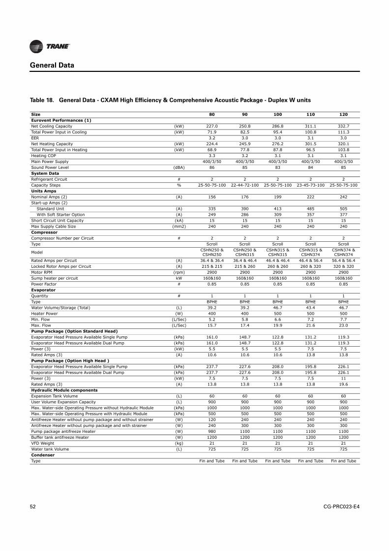
52 CG-PRC023-E4
General Data
Table 18. General Data - CXAM High Efficiency & Comprehensive Acoustic Package - Duplex W units
Size 80 90 100 110 120
Eurovent Performances (1)
Net Cooling Capacity (kW) 227.0 250.8 286.8 311.1 332.7
Total Power Input in Cooling (kW) 71.9 82.5 95.4 100.8 111.3
EER 3.2 3.0 3.0 3.1 3.0
Net Heating Capacity (kW) 224.4 245.9 276.2 301.5 320.1
Total Power Input in Heating (kW) 68.9 77.8 87.8 96.5 103.8
Heating COP 3.3 3.2 3.1 3.1 3.1
Main Power Supply 400/3/50 400/3/50 400/3/50 400/3/50 400/3/50
Sound Power Level (dBA) 86 85 83 84 85
System Data
Refrigerant Circuit # 2 2 2 2 2
Capacity Steps % 25-50-75-100 22-44-72-100 25-50-75-100 23-45-73-100 25-50-75-100
Units Amps
Nominal Amps (2) (A) 156 176 199 222 242
Start-up Amps (2)
Standard Unit (A) 335 390 413 485 505
With Soft Starter Option (A) 249 286 309 357 377
Short Circuit Unit Capacity (kA) 15 15 15 15 15
Max Supply Cable Size (mm2) 240 240 240 240 240
Compressor
Compressor Number per Circuit # 2 2 2 2 2
Type Scroll Scroll Scroll Scroll Scroll
ModelCSHN250 & CSHN250
CSHN250 & CSHN315
CSHN315 & CSHN315
CSHN315 & CSHN374
CSHN374 & CSHN374
Rated Amps per Circuit (A) 36.4 & 36.4 36.4 & 46.4 46.4 & 46.4 46.4 & 56.4 56.4 & 56.4
Locked Rotor Amps per Circuit (A) 215 & 215 215 & 260 260 & 260 260 & 320 320 & 320
Motor RPM (rpm) 2900 2900 2900 2900 2900
Sump heater per circuit kW 160&160 160&160 160&160 160&160 160&160
Power Factor # 0.85 0.85 0.85 0.85 0.85
Evaporator
Quantity # 1 1 1 1 1
Type BPHE BPHE BPHE BPHE BPHE
Water Volume/Storage (Total) (L) 39.2 39.2 46.7 43.4 46.7
Heater Power (W) 400 400 500 500 500
Min. Flow (L/Sec) 5.2 5.8 6.6 7.2 7.7
Max. Flow (L/Sec) 15.7 17.4 19.9 21.6 23.0
Pump Package (Option Standard Head)
Evaporator Head Pressure Available Single Pump (kPa) 161.0 148.7 122.8 131.2 119.3
Evaporator Head Pressure Available Dual Pump (kPa) 161.0 148.7 122.8 131.2 119.3
Power (3) (kW) 5.5 5.5 5.5 7.5 7.5
Rated Amps (3) (A) 10.6 10.6 10.6 13.8 13.8
Pump Package (Option High Head )
Evaporator Head Pressure Available Single Pump (kPa) 237.7 227.6 208.0 195.8 226.1
Evaporator Head Pressure Available Dual Pump (kPa) 237.7 227.6 208.0 195.8 226.1
Power (3) (kW) 7.5 7.5 7.5 7.5 11
Rated Amps (3) (A) 13.8 13.8 13.8 13.8 19.6
Hydraulic Module components
Expansion Tank Volume (L) 60 60 60 60 60
User Volume Expansion Capacity (L) 900 900 900 900 900
Max. Water-side Operating Pressure without Hydraulic Module (kPa) 1000 1000 1000 1000 1000
Max. Water-side Operating Pressure with Hydraulic Module (kPa) 500 500 500 500 500
Antifreeze Heater without pump package and without strainer (W) 120 240 240 240 240
Antifreeze Heater without pump package and with strainer (W) 240 300 300 300 300
Pump package antifreeze Heater (W) 980 1100 1100 1100 1100
Buffer tank antifreeze Heater (W) 1200 1200 1200 1200 1200
VFD Weight (kg) 21 21 21 21 21
Water tank Volume (L) 725 725 725 725 725
Condenser
Type Fin and Tube Fin and Tube Fin and Tube Fin and Tube Fin and Tube

CG-PRC023-E4 53
General Data
(1) Eurovent Cooling Mode Conditions (Evap. 12°C/7°C - Air. 35°C); Eurovent Heating Mode Condition (Evap. 40°C/45°C-Air. DB/WB 7°C/6°C)(2) Rated Condition without Pump Package(3) Single Pump Option(4) S: Single Speed, D: Two Speed, VFD: Inverter.(5) Base unit
Tube diameter (mm) 9.52 9.52 9.52 9.52 9.52
Number of Rows # 3 3 3 3 3
Fins per Foot (fpf) 192 192 192 192 192
Fan
Quantity # 8 8 10 12 12
Diameter (mm) 757 757 757 757 757
Drive Type Direct Direct Direct Direct Direct
Std Amb. Speeds per Circuit (4) 4×S 4×S 5×S 6×S 6×S
Low Amb. Speeds per Circuit (Option) (4) 1×VFD + 3×S 1×VFD + 3×S 1×VFD + 4×S 1×VFD + 5×S 1×VFD + 5×S
Airflow per Fan (m3/h) 9807 10301 9807 9805 9807
Static Pressure (Pa) 0 0 0 0 0
Power per Motor (kW) 0.4 0.3 0.4 0.4 0.4
Rated Amps per Motor (A) 1.35 1.35 1.35 1.35 1.35
Motor RPM (rpm) 700 700 700 700 700
PHR
Heat-Exchanger Type Brazed Plates Brazed Plates Brazed Plates Brazed Plates Brazed Plates
Victaulic Connection (mm) 64 64 64 64 64
Water Storage Capacity (L) 0.122*2 0.122*2 0.122*2 0.1647*2 0.1647*2
Unit Water Connection
Chilled Water (mm) 100 100 100 100 100
Type (Standard) Grooved Grooved Grooved Grooved Grooved
Dimensions
Unit Length with Buffer Tank (mm) 4230 5145 5145 6062 6062
Unit Length with VFD (mm) 4558 5473 5473 6388 6388
Unit Length with Buffer Tank and VFD (mm) 4558 5473 5473 6388 6388
Unit Length without Buffer Tank or VFD (mm) 4230 5145 5145 6062 6062
Unit Width (mm) 2273 2273 2273 2273 2273
Unit Height (mm) 2344 2344 2344 2344 2344
Weight (Aluminium Fins without louver or VFD)
Shipping Weight (5) (kg) 2810 3158 3365 3741 3752
Operating Weight (5) (kg) 2851 3199 3414 3787 3800
Additional weight (dual pump high head) (kg) 406 428 429 475 556
Additional weight (dual pump standard head) (kg) 324 347 347 473 473
Additional weight (single pump high head) (kg) 310 332 332 378 423
Additional weight (single pump standard head) (kg) 274 296 296 382 382
Additional weight (Buffer tank) (kg) 188 188 188 189 188
Louver Weight (kg) 47 51 51 56 56
Min. Starting/Oper. Ambient
Std Unit (°C) 7 7 7 7 7
Low Ambient (Option) (°C) -18 -18 -18 -18 -18
Refrigerant and Oil charge per circuit
Refrigerant charge (Kg) 45.4 54.4 56.2 66.2 66.2
Oil Charge (L) 13.4 13.4 13.4 13.9 14.4
Table 18. General Data - CXAM High Efficiency & Comprehensive Acoustic Package - Duplex W units
Size 80 90 100 110 120

54 CG-PRC023-E4
Controls
LCD Touch-Screen Display with Multi-Language Support
The standard DynaView display provided with the Trane CH530 control panel features an LCD
touch-screen that is navigated by file tabs. This is an advanced interface that allows the user to
access any important information concerning setpoints, active temperatures, modes, electrical
data, pressure, and diagnostics. It uses full text display available in 18 languages.
Display Features Include:
• LCD touch-screen with LED backlighting, for scrolling access to input and output operating
information
• Single-screen, folder/tab-style display of all available information on individual components
(evaporator, condenser, compressor, etc.)
• Password entry/lockout system to enable or disable display
• Automatic and immediate stop capabilities for standard or immediate manual shutdown
• Fast, easy access to available chiller data in tabbed format, including:
• Modes of operation, including normal cooling and heating as well as ice making
• Water temperatures and setpoints
• Loading and limiting status and setpoints
• Outdoor air temperature
• Start/stop differential timers
• Pump status and override
• Chilled and hot water reset settings
• Optional external setpoints, including:
• Chilled and hot water
• Demand limit
• Ice building

CG-PRC023-E4 55
Controls
Reports, listed on a single tabbed screen for easy access, including:
• ASHRAE, containing all guideline 3 report information
• Evaporator
• Condenser
• Compressor
Evaporator, condenser, and compressor reports containing all operational information on
individual components, including:
• Water temperatures
• Refrigerant pressures, temperatures, and approach
• Flow switch status
• EXV position
• Compressor starts and run-time
Alarm and diagnostic information, including:
• Flashing alarms with touch-screen button for immediate address of alarm condition
• Scrollable list of last ten active diagnostics
• Specific information on applicable diagnostic from list of over one-hundred
• Automatic or manual resetting diagnostic types
Adaptive Controls
Adaptive Controls directly sense the control variables that govern the operation of the unit:
evaporator pressure and condenser pressure. When any one of these variables approaches a limit
condition when damage may occur to the unit or shutdown on a safety, Adaptive Controls takes
corrective action to avoid shutdown and keep the unit operating. This happens through combined
actions of compressor and/or fan staging. Whenever possible, the unit is allowed to continue
making chilled or hot water. This keeps cooling capacity available unit the problem can be solved.
Overall, the safety controls help keep the building or process running and out of trouble.

56 CG-PRC023-E4
Controls
Stand-Alone Controls
Single heat pumps installed in applications without a building management system is simple to
install and control: only a remote auto/stop for scheduling is required for unit operation. Signals
from the hot/chilled-water pump contactor auxiliary, or a flow switch, are wired to the hot/chilled-
water flow interlock. Signals from a time clock or some other remote device are wired to the
external auto/stop input.
Standard Features
• Auto/Stop - A job-site provided contact closure turns the unit on and off.
• External Interlock - A job-site provided contact opening wired to this input turns the unit off and
require a manual reset of the unit microcomputer. This closure is typically triggered by a job-
site provided system such as a fire alarm.
Hardwire Points
Microcomputer controls allow simple interface with other control systems, such as time clocks,
building automation systems, and ice storage systems via hardwire points. This means you have
the flexibility to meet job requirements while not having to learn a complicated control system.
Remote devices are wired from the control panel to provide auxiliary control to a building
automation system. Inputs and outputs can be communicated via a typical 4–20 mA electrical
signal, an equivalent 2–10 Vdc signal, or by utilizing contact closures.
This setup has the same stand features as a stand-alone water chiller, with the possibility of having
additional optional features:
• Ice making control
• External chilled or hot water setpoint
• External demand limit setpoint
• Chilled water temperature reset
• Programmable relays - available outputs are: alarm-latching, alarm-auto reset, general
alarm, warning, chiller limit mode, compressor running, and Tracer control

CG-PRC023-E4 57
Controls
LonTalk LCI-C Interface with Modbus Interface
LonTalk (LCI-C) with ModBus communications capabilities are available, with communication link
via single twisted-pair wiring to factory-installed, tested communication board.
Required features:
• LonTalk LC I-C Interface w/ Modbus Interface
• Protocol Interface Controller
Modbus is a messaging structure developed by the Modicon to transfer and register data between
control devices. Modbus is a membership-based trade association that seeks to drive the adoption
of the Modbus communication protocol as the messaging structure that devices support. Modbus
is a system level communications protocol.
BACnet Interface
BACnet interface capabilities are available, with communication link via single twisted-pair wiring
to a factory-installed and tested communication board.
Required features:
• BACnet Interface (selectable option with chiller)
BACnet is a data communication protocol for building automation and control networks developed
by American Society of Heating, Refrigerating and Air-Conditioning Engineers (ASHRAE).
LonTalk LCI-C Interface
LonTalk (LCI-C) communications capabilities are available, with communication link via single
twisted-pair wiring to factory-installed, tested communication board.
Required features:
• LonTalk/Tracer Summit Interface (selectable option with chiller)
LonTalk is a communications protocol developed by the Echelon Corporation. The LonMark
association develops control profiles using the LonTalk communication protocol. LonTalk is a unit
level communications protocol.
LonTalk Communications Interface for Chillers (LCI-C) provides a generic automation system with
the LonMark chiller profile inputs/outputs. In addition to the standard points, Trane provides other
commonly used network output variables for greater interoperability with any automation system.
The complete reference list of Trane LonTalk points is available on the LonMark web site.
Trane controls or another vendor’s system can use the predefined list of points with ease to give
the operator a complete picture of how the system is running

58 CG-PRC023-E4
Controls
Tracer Summit
The chiller plant control capabilities of the Trane Tracer Summit building automation system are
unequaled in the industry. Trane’s depth of experience in chillers and controls makes us a well-
qualified choice for automation of chiller plants using air-cooled AquaStream3G chillers and heat
pumps. Our chiller plant automation software is fully pre-engineered and tested.
Required features:
• LonTalk/Tracer Summit Interface (selectable option with CGAM/CXAM)
• Building Control Unit (external device required)
Energy Efficiency
• Sequences starting of units to optimize the overall chiller plant energy efficiency
– Individual units operate as base, peak, or swing based on capacity and efficiency
– Automatically rotates individual unit operation to equalize runtime and wear between
chillers.
– Evaluates and selects the lowest energy consumption alternative from an overall
system perspective.
Easy Operation and Maintenance
• Remote monitoring and control
• Displays both current operation conditions and scheduled automated control actions
• Concise reports assist in planning for preventative maintenance and verifying performance
• Alarm notification and diagnostic messages aid in quick and accurate troubleshooting
When integrated with a Tracer Summit building management system the total building operation
can be optimized. With this system option, the full breadth of Trane’s HVAC and controls experience
are applied to offer solutions to many facility issues. If your project calls for an interface to other
systems, Tracer Summit can share data via BACnet an open systems protocol.

CG-PRC023-E4 59
Controls
Time of Day Scheduling
Time of day scheduling allows the customer to perform simple unit scheduling without the need
for a building automation system.
This feature allows the user to set ten events in a seven day time period. For each event the user
can specify an activation time and the days of the week the event is active. Any available setpoints
can be specified for each event, such as the leaving chilled water temperature (standard) and the
demand limit setpoint (optional if ordered).
Required features:
• Time of day scheduling (selectable option with chiller)
Additional options that if ordered may be incorporated into the scheduling:
• External chilled or hot water setpoint
• External demand limit setpoint
• Ice-making initiation
Tracer Sumit
or
LON
BACnet
Chiller Level
Controls
Building Level
Controls
BMS
BMS
BMS
BMS
NO - Normaly open contacts
NC - Normaly closed contacts
BMS - Generic building managment system
LCI - Lon Talk/Tracer Summit Interface
1A15 - Analog input/output
J2-1, 2
BCNT - Unit level BACnet interface
1A15 - Analog input/output
J2-1, 2
PRLY - Programmable relay outputs
1A18 - Binary output
1A18 - J2-1, 3/J2-2, 3 NO/NC
J2-4, 6/J2-5, 6 NO/NC
J2-7, 9/J2-8, 9 NO/NC
J2-10, 12/J2-11,12 NO/NC
SETA 4-20mA
SETB 2-10VDC
1A14 Analog input/output
J2-2, 3 Chilled water set point
J2-5, 6 Demand limit set point
ICE - Ice making status
1A16 - Binary input
J2-1, 2 NO
PCAP 2-10VDC output
1A25 Analog output
J2-4, 6
LCI-C
BACnet
Programmable Relay
External Chilled Water Setpoint
Demand Limit Setpoint
Ice Making with hard wire interface
Capacity Output
Chiller Level
Controls
Building Level
Controls
Tracer Sumit or
LON
BACnet
BSM
BSM
BSM
BSM
NO - Normaly open contactsNC - Normaly closed contactsBSM - Generic building managment system
LCI-CLCI - LonTalk/Tracer Summit Interface 1A15 - Analog input/output J2-1, 2
BACnetBCNT - Unit level BACnet interface 1A15 - Analog input/output J2-1, 2
Programmable RelayPRLY - Programmable relay outputs1A18 - Binary output 1A18 - J2-1, 3/J2-2, 3 NO/NCJ2-4, 6/J2-5, 6 NO/NCJ2-7, 9/J2-8, 9 NO/NCJ2-10, 12/J2-11, 12 NO/NC
External Chilled Water Setpoint Demand Limit Setpoint
SETA 4-20mASETB 2-10VDC1A14 Analog input/outputJ2-2, 3 Chilled Water set point J2-5, 6 Demand limit set point
Ice Making with hard wire interfaceICE - Ice making status 1A16 - Binary input J2-1, 2 NO
Capacity OutputPCAP 2-10VDC output 1A25 - Analog output J2-4, 6

60 CG-PRC023-E4
Dimensions
Table 19. Dimensions
Figure 4. Standard unit - SIMPLEX configuration
High Efficiency Standard Efficiency
CXAM CXAM
# o
f C
ircu
its
Comp.
Manifold Siz
e
Compact Super QuietComprehensive
acoustic packageCompact Super Quiet
Comprehensive
acoustic package
1 10 10 020 Simplex Frame 1 Simplex Frame 1
1 10 13 023
1 13 13 026 Simplex Frame 2 Simplex Frame 1
1 15 15 030
1 15 20 035 Simplex Frame 2 Simplex Frame 2
1 20 20 039
1 20 25 045 Simplex Frame 2
1 25 25 050
2 10 10 040 V Frame 1 V Frame 1
2 10 13 046 V Frame 2
2 13 13 052 V Frame 1
2 15 15 060 V Frame 2 V Frame 2
2 15 20 070
2 20 20 080 W Frame 2 V Frame 2
2 20 25 090 W Frame 2W Frame 3
W Frame 2
2 25 25 100 W Frame 3 W Frame 2
2 25 30 110W Frame 4 W Frame 3
2 30 30 120 W Frame 3 W Frame 2
2 20 20 25 130
2 20 25 25 140 W Frame 4 W Frame 3
2 25 25 25 150 W Frame 4
2 25 25 30 160 W Frame 4
2 25 30 30 170
Controlpanel
WireConnection
Height
Width
(height of fans)
Controlpanel
WireConnection
Height
Width
(height of fans)
Sound boxin option
Length
Compressors
Evaporator inlet

CG-PRC023-E4 61
Dimensions
Figure 5. Unit with Pump Package - SIMPLEX configuration
Figure 6. Pump package Water Connections - SIMPLEX configuration
Controlpanel
WireConnection
Height
Width
(height of fans)
Pump packageOutlet
Pump packageInlet
PHR Outlet
PHR Inlet
Controlpanel
WireConnection
Height
Width
(height of fans)
Sound boxin option
Evaporatoroutlet
Evaporatorinlet
Compressors
Length with buffer tank
VFDauxiliary
panelin option
Buffer tank

62 CG-PRC023-E4
Dimensions
Figure 7. SIMPLEX configuration
Figure 8. Standard unit + DUPLEX V configuration
Figure 9. Units with Pump Package - DUPLEX V configuration
Service clearance Mounting locations
without buffer tank
with buffer tank
Controlpanel
WireConnection
Height
Width
(height of fans)
Length
Compressors
Length
Evaporator inlet
Evaporator outlet
Controlpanel
WireConnection
WireConnection
Height
Width
(height of fans)
CompressorsCompressors
Fans Buffer tank
Pump package
Length with buffer tank
Length without buffer tank
VFDoption
Sound boxin option for
compressors
Pump packageVFD in option

CG-PRC023-E4 63
Dimensions
Figure 10. Pump Package Water Connections - DUPLEX V configuration
Figure 11. DUPLEX V configuration
PHR/THR Outlet
PHR/THR Intlet
Mounting locationsService clearance
Figure 12. Standard Unit - DUPLEX W configuration
Controlpanel
WireConnection
Height
Width
(height of fans)
Controlpanel
WireConnection
Height
Width
(height of fans)
Sound boxin option
Compressors
Length
Evaporator inlet
Evaporator outlet

64 CG-PRC023-E4
Dimensions
Figure 13. Units with Pump Package - DUPLEX W configuration
Figure 14. Pump Package Water Connections - DUPLEX W configuration
Figure 15. DUPLEX W configuration
Controlpanel
WireConnection
Height
Width
(height of fans)
Sound boxin option
Compressors
Length
Pump package
VFD auxiliary panelin option
Fans
Pump packageOutlet
Pump packageIntlet
without buffer tank
with buffer tank
without buffer tank
with buffer tank
only for

CG-PRC023-E4 65
Dimensions
Table 20. Dimensions SIMPLEX
Table 21. Dimensions Duplex V
FRAME 1 FRAME 2
α → Without buffer tankb → With buffer tank
α → Without buffer tankb → With buffer tank
Unit mm mm
Lengthα → 2908b → 3388
α → 3822b → 4302
Width 1301 1301
Height 2145 2145
Lifting holesA 534 556
B 1867 2720
EVP water connections(base unit)
C 246 246
D 516 516
E 488 488
EVP water connections (unit with buffer tank)
F 572 572
G 325 325
H 249 249
I 244 244
EVP water connections(unit with pump package,
without buffer tank)
J 323 323
K 1016 1016
L 246 246
M 287 287
Partial Heat Recovery water connections
N 1176 2091
O 182 182
P 385 385
Isolators positionQ 534 558
R 2571 3358
FRAME 1 FRAME 2
α → Without buffer tankb → With buffer tank
α → Without buffer tankb → With buffer tank
Unit mm mm
Lengthα → 2905b → 3416
α → 3819b → 4330
Width 2266 2266
Height 2150 2150
Lifting holesA 615 615
B 1650 2564
EVP water connections (base unit)
C 198 198
D 655 790
E 371 371
EVP water connections (unit with pump package,
without buffer tank)
F 211 211
G 1646 1646
H 480 480
I 500 500
EVP water connections(unit with buffer tank)
J1 303 303
J2 695 695
K 1796 1796
Partial Heat Recovery water connections
L 1125 1125
M 1158 1158
N 1392 1392
Isolators position
O 494 494
P 2027
Q 2388 3299

66 CG-PRC023-E4
Dimensions
Table 22. Dimensions DUPLEX W
FRAME1 FRAME2 FRAME3 FRAME4
Unit mm mm mm mm
Length 3647 4230 5145 6062
Width 2273 2273 2273 2273
Height 2344 2344 2344 2344
Lifting holesA 767 767 767 767
B 1647 2155 3023 3810
EVP water connections (base unit)
C 198 198 198 198
D 790 790 790 790
E 292 292 292 292
EVP water connections (unit with pump package,
without buffer tank)
F 292 292 292 292
G 198 198 198 198
H 574 574 574 574
I 734 734 734 734
Isolators position
J 767 767 767 767
K 2126 2267 1767 1767
L 3317 4139
M 3148 3731 4139 5566

CG-PRC023-E4 67
Mechanical Specifications
General
• Operates with HFC-based refrigerant R410A.
• Furnished with scroll compressors, brazed plate evaporator, with microprocessor-based
control
• Complies with EC requirements for Machinery, Electromagnetic and Pressure Equipment
Directives (98/37/CE directive), as amended, and with national implementing legislation
• Manufactured and tested in accordance with the quality assurance ISO 9001/BS EN ISO9001
• Manufactured and tested in ISO 14001 certified factories for a better respect of the environment
• Certified and rated in accordance with Eurovent standards
• Units are constructed of galvanized steel frame with galvanized steel panels
• Component surfaces are finished with a powder-coated paint
• Each unit ships with full operating charges of refrigerant and oil
Compressor and Motor
The unit is equipped with two or more hermetic, direct-drive, 3000 rpm 50 Hz suction gas-cooled
scroll compressors. The simple design has only three major moving parts and a completely
enclosed compression chamber which leads to increased efficiency. Overload protection is internal
to the compressors. The compressor includes: centrifugal oil pump, oil level sight glass and oil
charging valve. Each compressor will have compressor heaters installed and properly sized to
minimize the amount of liquid refrigerant present in the oil sump during off cycles.
Unit-Mounted Starter
The control panel is designed per IP-54. The starter is available in a solid-state soft starter or across-
the-line configuration, factory-mounted and fully pre-wired to the compressor motor and control
panel. Power line connection type is standard with a fused disconnect switch.
Disconnect Switch
A non-fused molded case disconnect switch, factory pre-wired with terminal power and equipped
with a lockable external operator handle, is available to disconnect the chiller from main power.
Evaporator (Condenser for CXAM in heating mode)
Braze plate heat exchanger is made of stainless steel with copper as the braze material. It is
designed to withstand a refrigerant side working pressure of 45 bars and a waterside working
pressure of 10.0 bars. Evaporator is tested at 1.1 times maximum allowable refrigerant side working
pressure and 1.5 times maximum allowable water side working pressure. It has one water pass.
Blanket heater secures the evaporator from freezing to an ambient of -18°C.
The evaporator is covered with factory-installed 0.75 inch (19.05 mm) Armaflex II or equal (k=0.28)
insulation. Foam insulation is used on the suction line. Water pipe extensions with insulation go
from the evaporator to the edge of the unit.
All evaporators are tested and stamped in accordance with PED.

68 CG-PRC023-E4
Mechanical Specifications
Condenser (Evaporator for CXAM in cooling mode)
Air-cooled coils have aluminium fins mechanically bonded to internally-finned copper tubing. The
condenser coil has an integral subcooling circuit. The maximum allowable working pressure of the
condenser is 45.0 bars. Condensers are factory proof and leak tested at 50.0 bars.
Direct-drive vertical discharge condenser fans are balanced. Three-phase condenser fan motors
with permanently lubricated ball bearings and external thermal overload protection are provided.
Cooling only units (CGAM) are able to operate from -18°C to 52°C ambient.
Reversible units (CXAM) in cooling mode are able to operate from -10°C to 46°C ambient.
Reversible units (CXAM) in heating mode are able to operate from -10°C to 20°C ambient.
Refrigerant Circuit and Capacity Modulation
Each refrigerant circuit has scroll compressors piped in parallel with a passive oil management
system. A passive oil management system maintains proper oil levels within compressors and has
no moving parts. Each refrigerant circuit includes
• Filter drier : 1 on each liquid line (1 for Cooling only units / 2 for Reversible units)
• Electronic expansion valve.
Capacity modulation is achieved by turning compressors on and off. Units with single circuit have
two capacity stages. Units with dual circuit have four capacity stages.
Unit Controls (Trane CH530)
The microprocessor-based control panel is factory-installed and factory-tested. The control system
is powered by a pre-wired control power transformer, and will turn on and off compressors to meet
the load. Microprocessor-based chilled water reset based on return water is standard.
The Trane CH530 microprocessor automatically acts to prevent unit shutdown due to abnormal
operating conditions associated with low evaporator refrigerant temperature and high condensing
temperature. If an abnormal operating condition continues and the protective limit is reached, the
machine will shut down.
The panel includes machine protection for the following conditions:
• Low evaporator refrigerant temperature and pressure
• High condenser refrigerant pressure
• Critical sensor or detection circuit faults
• High compressor discharge temperature (with low temp evaporator)
• Lost communication between modules
• Electrical distribution fault: phase reversal
• External and local emergency stop
• Loss of evaporator water flow

CG-PRC023-E4 69
Mechanical Specifications
When a fault is detected, the control system conducts more than 100 diagnostic checks and displays
results. The display will identify the fault, indicate date, time, and operating mode at time of
occurrence, and provide type of reset required and a help message.
Clear Language Display Panel
Factory-mounted to the control panel door, the operator interface has an LCD touch-screen display
for operator input and information output. This interface provides access to the following
information: evaporator report, condenser report, compressor report, operator settings, service
settings, service tests, and diagnostics. All diagnostics and messages are displayed in “clear
language.”
Data contained in available reports includes:
• Water and air temperatures
• Refrigerant pressures and temperatures
• Flow switch status
• EXV position
• Compressor starts and run-time
All necessary settings and setpoints are programmed into the microprocessor-based controller via
the operator interface. The controller is capable of receiving signals simultaneously from a variety
of control sources, in any combination, and priority order of control sources can be programmed.
The control source with priority determines active setpoints via the signal it sends to the control
panel. Control sources may be:
• Local operator interface (standard)
• Hard-wired 4-20 mA or 2-10 Vdc signal from an external source (interface optional; control
source not supplied)
• Time of day scheduling (optional capability available from local operator interface)
• LonTalk LCI-C (interface optional; control source not supplied)
• BACNet (interface optional; control source not supplied)
• ModBus (interface optional; control source not supplied)
• Trane Tracer Summit system (interface optional; control source not supplied)
Quality Assurance
The quality management system applied by Trane has been subject to independent third-party
assessment and approval to ISO 9001. The products described in this catalog are designed,
manufactured and tested in accordance with the approved system requirements described in the
Trane Quality Manual.

70 CG-PRC023-E4
Options
Options
Application Options
Ice-Making with Hardwired Interface
Unit controls are factory set to handle ice-making for thermal storage application. This option
allows for full load operation of the chiller with leaving evaporator water temperature between -
7°Cand 18°C.
Low-Temperature Processing
An additional temperature sensor, at the compressor discharge, enables leaving evaporator
water temperature below 5.5°C.
Sound Options
Compact
This option includes 920 rpm fans.
Super Quiet Unit
This option includes low speed 700 rpm fans and compressor sound jackets.
Super Quiet with Night Noise Setback
This option will provide two speed fan motors. At night, on a contact closure all the fans run at low
speed bringing the overall sound level further down.
Comprehensive Acoustic Package
This option includes low speed 700 rpm fans and acoustical treatment for compressors and
refrigerant lines.

CG-PRC023-E4 71
Options
Pump Options
Single Standard and High Head Pump Package
Pump package includes: a standard or high head pump, air separator with vent, expansion vessel,
drainage valves, and service valves to isolate pump for repair/replacement.
The pump option is single point power integrated into the chiller unit power. The control of the
pump is integrated into the chiller controller. The CH530 displays evaporator pump starts and run-
times. Freeze protection down to an ambient of -18°C is included as standard. The cold part of the
pump package will also be insulated.
Standard head pump is offered for applications that have short water loops or are de-coupled. High
head pump is offered for applications where the integrated chiller pump serves the entire loop
volume.
Dual Standard and High Head Pump Package
Pump package includes: two standard or high head pumps, air separators with vents, expansion
vessels, drainage valves, and service valves to isolate each pump for repair/replacement.
The pump package is single point power integrated into the chiller unit power. The control of the
pump is integrated into the chiller controller. The CH530 displays evaporator pump starts and run-
times. Freeze protection down to an ambient of -18°C is included as standard. The cold parts of the
pump package will also be insulated.
Designed with one redundant pump, it is controlled to operate both pumps through a lead/lag and
failure/recovery functionality.
Standard head pump is offered for applications that have short water loops or are de-coupled. High
head pump is offered for applications where the integrated chiller pump serves the entire loop
volume.
Dual Contactors for Pump (field installed pumps)
Dual pump contacts to control two remote pumps are included in the control panel.
Single Contactor for Pump (field installed pumps)
Single pump contact to control a remote pump is included in the control panel.
Pump Flow Controlled by Mechanical Balancing Valve
A mechanical balancing valve is installed. This option replaced the outlet shut off valve.
Pump Flow Controlled by Variable Speed Drive
A variable speed drive is installed in an additional panel to control the pump. The inverter is
adjusted upon start up to balance the system flow and head requirements. The purpose is to save
on wasted pump energy caused by a traditional balancing valve.

72 CG-PRC023-E4
Options
Buffer Tank (only available with pump package)
The water tank is factory-installed for easy installation at the building site. The tank is engineered
for continuous flow and is fully insulated as standard and is designed with freeze protection down
to -18°C. The purpose of the tank is to increase the chilled water circuit inertia, which is necessary
with short water loops. A high circuit inertia reduces the compressor’s cycling to increase the
compressor life span and allow for more precise water temperature accuracy. It also saves energy
as compared to hot gas bypass.
Electrical Options:
Across-the-Line Starter/Direct on Line
Across-the-line starter is unit mounted with a IP-54 gasketed enclosure.
Across-the-Line Starter/Power Factor Correction
Across-the-line starter is unit mounted with a IP-54 gasketed enclosure. Power factor correction
capacitors are factory-installed to correct power factor to 0.95 at all loads.
Solid-State Soft Starter
This option unit mounted starter has a IP-54 gasketed enclosure. To extend starter life contactors
bypass current from the silicon control rectifies (SCRs) after startup.
Solid-State Soft Starter/Power Factor Correction
This option unit mounted starter has a IP-54 gasketed enclosure. To extend starter life contactors
bypass current from the silicon control rectifies (SCRs) after startup. Power factor correction
capacitors are factory-installed to correct power factor to 0.95 at all loads.

CG-PRC023-E4 73
Options
Control Options:
LonTalk/Tracer Summit Interface
LonTalk (LCI-C) or Tracer Summit communications capabilities are available with communication
link via single twisted-pair wiring to factory-installed and tested communication board. This option
will support the functionality required to obtain Lon Mark certification.
LonTalk LCI-C Interface with Modbus Interface
Allows user to easily interface with Modbus through LonTalk via a single twisted-pair wiring to
factory-installed and tested communication board.
Time of Day Scheduling
Time of day scheduling capabilities are available for scheduling single chiller applications through
Trane CH530 panel (without the need for building automation system - BAS). This feature allows
the user to set up to ten events in a seven day time period.
External Chilled Water and Demand Limit Setpoint
Controls, sensors, and safeties allow reset of chilled water temperature, based on temperature
signal, during periods of low outdoor air temperature (chilled water reset based on return chilled
water temperature is standard). The demand limit setpoint is communicated to a factory-installed
and tested communication board through a 2-10 Vdc or 4-20 mA signal.
Percent Capacity
Output the number of compressors that are operating as an analog 2-10 Vdc or 4-20 mA signal.
Programmable Relays
Predefined, factory-installed, programmable relays allow the operation to select four relay outputs.
Available outputs are: Alarm-Latching, Alarm-Auto Reset, General Alarm, Warning, Chiller Limit
Mode, Compressor Running, and Tracer Control.

74 CG-PRC023-E4
Options
Other Options
Access Guards
A coated wire mesh that covers the coil along the side of the unit.
Access Guards and Half Louvers
A coated wire mesh covers the access area under the condenser coils and half louvers cover the
condenser coil.
Architectural Louvered Panels
Louvered panels cover the complete condensing coil and service area beneath the condenser.
Half Louvers
Louvered panels cover the condenser coil only. Available on the W coil units only.
Non-Lanced Aluminum Fins
Aluminum fins without slits help to prevent sand clogging the slit portion of a standard fin.
Non-Lanced Aluminum Fins with Pre-Coat Black Epoxy
This option uses pre-coated black epoxy non-slit aluminum fin stock for corrosion protection.
Non-Lanced Aluminum Fins with Pre-Coat Blue Fin
This option uses pre-coated non-slit aluminum fin stock to limit coil freezing and then defrost cycle.
Neoprene Pads
Neoprene isolator pads specially dimensioned to reduce vibration transmission to the
supporting structure when the unit is installed. Pads ship in the control panel.
Isolators
Molded elastomeric isolators sized to reduce vibration transmission to the supporting structure
when the unit is installed. Isolators ship with the chiller.
Flange Adapter
Kit to convert both water connections from grooved pipe to flanged connections. This includes:
grooved couplings and grooved to flange adapters.

CG-PRC023-E4 75
Hydraulic Data
Figure 16. Pressure drops (through the evaporator - S configuration)
Figure 17. Pressure drops (through the evaporator - V and W configurations)
1 20 SE - 23SE - 26 SE SQ - 26 SE CP2 30 SE SQ - 30 SE CP3 20 HE - 23 HE SQ - 23 HE CP4 23 HE CAP - 26 HE CAP - 30 HE SQ
- 30 HE CP - 30 SE CAP5 26 HE SQ - 26 HE CP - 30 HE CAP
- 35 SE6 35 HE - 39 SE7 45 SE - 50 SE
8 40 SE9 40 HE - 46 HE SQ - 46 HE CP
- 46 SE - 52 SE10 52 HE - 46 HE CAP - 60 HE - 60 SE11 70 SE12 80 SE - 90 SE CAP13 70 HE - 90 SE SQ - 90 SE CP14 80 HE SQ - 80 HE CP - 100 SE
- 110 SE - 120 SE CAP15 80 HE CAP - 90 HE - 110 HE SQ
- 110 HE CP - 120 SE SQ - 120 SE CP - 140 SE
16 100 HE - 110 HE CAP - 120 HE - 140 HE - 150 HE - 150 SE - 160 HE - 160 SE - 170 SE

76 CG-PRC023-E4
Hydraulic Data
Figure 18. Pressure drops through the strainer
Figure 19. Available pressure - S coil configuration - Standard head
A 20 HE - 23 HE SQ - 23 HE CP - 26 SE CAP
B 20 SE - 23 SE - 26 SE SQ - 26 SE CPC 23 HE CAP -26 HE CAPD 26 HE SQ - 26 HE CP - 30 HE SQ
- 30 HE CP - 30 SE CAPE 30 SE SQ - 30 SE CPF 30 HE CAP - 35 SEG 45 SE - 50 SEH 35 HEI 39 SE

CG-PRC023-E4 77
Hydraulic Data
Figure 20. Available pressure - S coil configuration - High head
Figure 21. Available pressure - V and W coil configurations - Standard head
A 20 HE - 20 SE - 23 SE - 23 HE SQ - 23 HE CP - 26 SE
B 26 HE SQ - 26 HE CP - 30 HE SQ - 30 HE CP - 30 SE
C 23 HE CAP - 26 HE CAP - 46 HE CAP - 52 HE
D 30 HE CAP - 35 SEE 35 HE - 39 SEF 45 SE - 50 SE
J 40 HE - 46 HE SQ - 46 HE CP - 46 SE - 52 SE
K 40 SEL 46 HE CAP - 52 HEM 60 HE - 60 SEO 70 HE - 90 SE SQ - 90 SE CPP 70 SEQ 80 HE SQ - 80 HE CP - 100 SER 80 SES 80 HE CAP - 90 HE - 100 HET 90 SE CAPU 110 HE - 120 HE - 120 SE SQ
- 120 SE CPV 110 SE - 120 SE CAPW 140 HE - 140 SE - 150 HE - 150 SE
- 160 HE - 160 SE - 170 SE

78 CG-PRC023-E4
Hydraulic Data
Figure 22. Available pressure - V and W coil configurations - High head
E 40 SEF 40 HE - 46 HE SQ - 46 HE CP
- 46 SE - 52 SEG 60 SE - 60 HEH 70 SEI 70 HE - 90 SE SQ - 90 SE CPJ 80 HE SQ - 80 HE CP - 100 SE
- 110 SEK 80 SEL 80 HE CAP - 90 HE - 100 HE - 110 HEM 120 HE - 140 HE - 150 HE - 150 SE
- 120 SE SQ - 120 SE CP N 120 SE CAPO 160 HE - 160 SE - 170 SE

79 CG-PRC023-E4
Operating Map
A = Entering air temperature (°C)B = Leaving water temperature (°C)1 = Standard operating map2 = Low ambient operating map (requires inverter)3 = Part load operating map
Figure 23. Operating map - cooling mode

80 CG-PRC023-E4
Operating Map
Figure 24. Operating map - heating mode
A = Entering air temperature (°C)B = Leaving water temperature (°C)1 = Standard operating map

CG-PRC023-E4 81
Unit Schematics
Unit Schematics
Figure 25. Hydraulic module water chart
1 Single or Dual Pump 8 Exchanger
2 Water Strainer 9 Automatic Air Bleed
3 Shut Off Valve 10 Manual Air Bleed
4 Shut off or Balancing Valve 11 Drain Valve
5 Valve for Pressure Point 12 Antifreeze Protection
6 Expansion Tank 13 Buffer Tank
7 Relief valve
Pi Gauge A Optional Buffer Tank
FT Water Flow Switch B Pump box
T1 Evap Water Inlet Temp Sensor C Optional balancing valve
T2 Evap Water Outlet Temp Sensor
Water Line Insulated Water Line

82 CG-PRC023-E4
Unit Schematics
Figure 26. CXAM Refrigerant Circuit - W coil configuration without dedicated subcooler
C1 = circuit 1C2 = circuit 2CP = Control panelDL = Discharge lineSL = Suction lineLL = Liquid line1 = Scroll compressor2 = Evaporator3 = Condenser4 = Partial heat recovery exchanger5 = Filter drier (cooling mode)6 = Electronic expansion valve
(cooling mode)7 = Service valve8 = Schraeder valve9 = Sight glass10 = Receiver11 = 4 way reversing valve12 = Filter drier (heating mode)13 = Electronic expansion valve
(heating mode)14 = Receiver fill valve15 = Receiver check valvePT = Pressure transducerPZH = High pressure switchTT = Temperature sensorTCE = Electronic expansion valveFSL = Evaporator water flow switch
REFRIGERANT LINE
CHILLED / HEATED WATER LINE
INSULATION
ONLY FOR CXAM «W» 140-150-160-170
PARTIAL HEAT RECOVERY OPTION

CG-PRC023-E4 83
Unit Schematics
Figure 27. CXAM Refrigerant Circuit - W coil configuration with dedicated subcooler
C1 = circuit 1C2 = circuit 2CP = Control panelDL = Discharge lineSL = Suction lineLL = Liquid line1 = Scroll compressor2 = Evaporator3 = Condenser4 = Partial heat recovery exchanger5 = Filter drier (cooling mode)6 = Electronic expansion valve
(cooling mode)7 = Service valve8 = Schraeder valve9 = Sight glass10 = Receiver11 = 4 way reversing valve12 = Filter drier (heating mode)13 = Electronic expansion valve
(heating mode)14 = Receiver fill valve15 = Receiver check valvePT = Pressure transducerPZH = High pressure switchTT = Temperature sensorTCE = Electronic expansion valveFSL = Evaporator water flow switch
REFRIGERANT LINE
CHILLED / HEATED WATER LINE
INSULATION
ONLY FOR CXAM «W» 140-150-160-170
PARTIAL HEAT RECOVERY OPTION

84 CG-PRC023-E4
Unit Schematics
Figure 28. CXAM Refrigerant
Circuit - S and V
coil configurations
C1 = circuit 1C2 = circuit 2CP = Control panelDL = Discharge lineSL = Suction lineLL = Liquid line1 = Scroll compressor2 = Evaporator3 = Condenser4 = Partial heat recovery exchanger5 = Filter drier (cooling mode)6 = Electronic expansion valve
(cooling mode)7 = Service valve8 = Schraeder valve9 = Sight glass10 = Receiver11 = 4 way reversing valve12 = Filter drier (heating mode)13 = Electronic expansion valve
(heating mode)14 = Receiver fill valve15 = Receiver check valvePT = Pressure transducerPZH = High pressure switchTT = Temperature sensorTCE = Electronic expansion valveFSL = Evaporator water flow switch
REFRIGERANT LINE
CHILLED / HEATED WATER LINE
INSULATION
ONLY FOR CXAM V, CXAM S has one
refrigerant circuit
PARTIAL HEAT RECOVERY OPTION


Trane optimizes the performance of homes and buildings around the world. A business of Ingersoll Rand, the leader
in creating and sustaining safe, comfortable and energy efficient environments, Trane offers a broad portfolio of ad-
vanced controls and HVAC systems, comprehensive building services, and parts.
For more information, visit www.Trane.com.
Trane has a policy of continuous product and product data improvement and reserves the right to change design and specifications without notice.
© 2011 Trane All rights reserved
CG-PRC023-E4 March 01, 2011
Digitally printed on environmentally friendly paper;produced using fewer trees and chemicals and lessenergy.