Embed Size (px)
Citation preview

PRO COMP SUSPENSION
Suspension Systems that Work!
2360 Boswell Road Chula Vista, CA 91914 Phone 619.216.1444 Fax 619.216.1474 E-Mail [email protected]
This document contains very important information that includes warranty information and instructions for resolving problems you may encounter. Please keep it in the vehicle as a permanent record.
Part # 52098 97’-03’ Ford F/S 4WD IFS F150-F250 5.4L w/ E4OD Transmission 4” Suspension System

INSTALLATION INSTRUCTIONS
ITEM#
Revised: 5.5.06
Ph:(619) 216-1444 Fax:(619) 216-1474 E-Mail: [email protected] Website: www.explorerprocomp.com
2
PARTS LIST: DESCRIPTION QTY. ILLUST.
Box 1 of 3
90-1402 90-1460 90-1461 90-1462 90-1463 90-2181 90-6164
70-0625501800
Front Crossmember Rear Crossmember Crossmember Support Bracket (Driver) Crossmember Support Bracket (Passenger) Differential Drop Bracket Bumpstop Bracket Hardware Pack
5/8” x 5-1/2” USS GR8 Hex Bolt
1 19,22,24 1 1 1 2 2
4
19,20,23 23 23
17,18,22 27
Inst. 5 1 4 1 8 2
24 Inst. 5
24 Inst. 5
24
70-0506001800 72-06200100816 72-05000100512 73-06200034 73-05000030
1/2” x 6” USS GR8 Hex Bolt 5/8” USS Stover Nut 1/2” USS Nylock Nut 5/8” SAE Hardened Flat Washer 1/2” SAE Flat Washer
90-6165 90-1216
Hardware Pack Load Washer - 1.50” O.D. x .532” I.D. 3 24,28
2 2 1
30 26 24
90-1539 90-2089 90-2215
Brake Line Extension - F150 Sway Bar Spacer Tube Spacer - 1.0” x .219” Wall x 3.75”
THIS INSTRUCTION PACKET CONTAINS WARRANTY INFORMATION AND SHOULD BE KEPT IN THE VEHICLE AS A PERMANENT RECORD.
NOTE: 99-03 F150 4WD MODELS EQUIPPED WITH A 4R70W TRANSMISSION REQUIRE P/N 52097 OR KIT REFRENCE # K4050. 97-01 MODELS WITH A E40D REQUIRE P/N 52098 OR KIT REFRENCE # K4051. THE 4R70W TRANSMISSION CAN BE IDENTIFIED BY A 13”x 13” PAN AND THE E40D TRANSMISSION HAS A 13”X 26” PAN.
Pro Comp Suspension, Inc. Chula Vista, CA USA

90-6166 Hardware Pack
3
70-03711002800 3/8” x 11” SAE GR8 Hex Bolt 2 26 70-0431251800 72-03700100817 72-04300100816 73-03700030 73-04300034
7/16” x 1-1/4” USS GR8 Hex Bolt 3/8” SAE GR8 Stover Nut 7/16” USS GR8 Stover Nut 3/8” SAE Flat Washer 7/16” SAE Hardened Flat Washer
4 23 2 26 4 23 8 26 8 23
90-6167 Hardware Pack 70-0503751800 1/2” x 3-3/4” USS GR8 Hex Bolt 1 17 71-121001501090 72-05000100816 73-12150816 73-05000034
12MM x 1.50 x 100MM GR10.9 Bolt 1/2” USS Stover Nut 12MM x 1.50 GR10.9 Stover Nut 1/2” SAE Hardened Flat Washer
1 18 1 17 1 18 4 17,18
90-6183 Hardware Pack 70-0310751500 5/16” x 3/4” USS GR5 Hex Bolt 2 30 70-0501251800 72-03100100512 72-05000100512 73-03100030
1/2” x 1-14” USS GR8 Hex Bolt 5/16” USS Nylock Nut 1/2” USS Nylock Nut 5/16” SAE Flat Washer
2 27 2 30 2 27 4 30
73-05000031 1/2” SAE Flat Washer 4 27
Box 2 of 3
90-4025 Front Spindle (Driver) 1 25 90-4024 Front Spindle (Passenger) 1 25
Box 3 of 3
90-1104 Compression Strut Mount 2 29 90-1512 Trans Crossmember 1 29 90-1540 Trans Crossmember Mount (Driver) 1 29
1 1
21 21
90-2216 90-2217
Vent Tube Extension Hose Nipple - 5/16” Brass
90-6189 Hardware Pack
QTY. ILLUST. ITEM# DESCRIPTION
90-1541 Trans Crossmember Mount (Passenger) 1 29

4
90-6123 Compression Strut Pack 15-11148 Differential Mount Bushing 8 29 90-2109 90-2110
GM Compression Strut Sleeve GM Compression Strut Sleeve
4 29 2 28
90-6184 Hardware Pack 70-0504001800 1/2” x 4” USS GR8 Hex Bolt 4 29 73-05000030 72-05000100512
1/2” SAE Flat Washer 1/2” USS Nylock Nut
8 29 4 29
90-6185 Hardware Pack Torsion Drop 70-0503501800 1/2” x 4” USS GR8 Hex Bolt 4 28 70-0505001800 73-05000030
1/2” x 5” USS GR8 Hex Bolt 1/2” SAE Flat Washer
2 28 12 28
72-058000100816 1/2” USS Stover Nut 6 28
* * The following parts are used in conjunction with this kit. They must be ordered separately. * *
ITEM# DESCRIPTION QTY. 320510 329510 13132 22259
ES 3000 Shocks (Front) ES 3000 Shocks (Rear) Add-A-Leaf Kit U-Bolt Rear Kit
2 2 2 1
QTY. ILLUST. ITEM# DESCRIPTION
90-2218 Compression Strut 2 29 90-4032 Torsion Crossmember, Spacer 2 28
90-6188 Hardware Pack 70-0371001800 3/8” x 1” USS GR8 Hex Bolt 2 29 70-0501001500 73-03700030
1/2” x 1-1/4” USS GR8 Hex Bolt 3/8” SAE Flat Washer
12 29 2 29
73-03700036 3/8” Split Lock Washer 2 29 73-05000030 1/2” SAE Flat Washer 24 29 72-05000100816 1/2” USS Stover Nut 12 29
BEFORE YOU BEGIN:
• Installation requires a professional mechanic.
MX6007 MX6006 MX-6 Shocks (Front)
MX-6 Shocks (Rear) 2 2

5
PLEASE NOTE: Due to differences in manufacturing, dimensions and inflated measurements, tire and wheel combinations should be test fit prior to installation. Tire and wheel choice is crucial in assuring proper fit, performance, and the safety of your Pro Comp equipped vehicle. For this application, we recommend a wheel not to exceed 8” in width with a minimum back-spacing of 4” must be used, additionally, a quality tire of radial design, not exceeding 35” tall X 12.5” wide is also rec-ommended. Please note that the use of a 35” X 12.5” tire may require fender modification. Violation of these recom-mendations will not be endorsed as acceptable by Pro Comp Suspension and will void any and all warranties either writ-ten or implied.
♦ This installation requires a professional mechanic! ♦ We recommend that you have access to a GM service manual for your vehicle to
assist in the disassembly and reassembly of your vehicle. It contains a wealth of de-tailed information.
♦ Prior to installation, carefully inspect the vehicle’s steering and driveline systems paying close attention to the tie rod ends, ball joints, wheel bearing preload, pitman and idler arm. Additionally, check steering-to-frame and suspension-to-frame at-taching points for stress cracks. The overall vehicle must be in excellent working condition. Repair or replace all worn or damaged parts!
♦ Read the instructions carefully and study the illustrations before attempting installa-tion! You may save yourself a lot of extra work.
♦ Check the parts and hardware against the parts list to assure that your kit is com-plete. Separating parts according to the areas where they will be used and placing the hardware with the brackets before you begin will save installation time.
♦ Check the special equipment list and ensure the availability of these tools. ♦ Secure and properly block vehicle prior to beginning installation. ♦ ALWAYS wear safety glasses when using power tools or working under the vehicle! ♦ Use caution when cutting is required under the vehicle. The factory undercoating is
flammable. Take appropriate precautions. Have a fire extinguisher close at hand. ♦ Foot pound torque readings are listed on the Torque Specifications chart at the end
of the instructions. These are to be used unless specifically directed otherwise. Ap-ply thread lock retaining compound where specified.
♦ Please note that while every effort is made to ensure that the installation of your Pro Comp lift kit is a positive experience, variations in construction and assembly in the vehicle manufacturing process will virtually ensure that some parts may seem difficult to install. Additionally, the current trend in manufac-turing of vehicles results in a frame that is highly flexible and may shift slightly on disassembly prior to installation. The use of pry bars and tapered punches for alignment is considered normal and usually does not indicate a faulty product. However, if you are uncertain about some aspect of the instal-lation process, please feel free to call our tech support department at the number listed on the cover page. We do not recommend that you modify the Pro Comp parts in any way as this will void any warranty expressed or im-plied by the Pro Comp Suspension company.

6
* * The following special tools will be required for the proper removal and or installation of this kit * *
• Pro Comp offers skid plates, traction bars, steering stabilizers and a full line of All Terrain and Mud Terrain Tires. Contact dealer for details.
FRONT DISASSEMBLY
1) Put vehicle in neutral. Place floor jack under lower control arm’s front crossmember and raise vehicle. Place jack stands under frame rails, behind front wheel wells and lower frame onto stands. Put vehicle in gear, set emergency brake and block rear wheels, in front and behind tires. Remove front wheels.
• Front end realignment is necessary.
• Speedometer recalibration is necessary if bigger tires (10% larger than stock diameter) are installed.
• This system utilizes the stock torsion bar which normally affords the best ride quality. If, after kit is installed, ride/handling seems too “soft”, heavier Gross Vehicle Weight Rating (GVWR) bars can be installed. Contact your local Ford dealer for more details.

7
2) Install Torsion Bar tool (T95T-5310-A) with Adapter Plates (T96T-5310-A) (Illustration 1). Tighten torsion bar tool until it touches torsion bar adjuster. Measure the depth of the adjuster bolt for replacement of torsion bar adjusters. Remove torsion bar adjuster bolt and nut. Remove torsion bar adjuster and repeat on opposite side.
NOTE: If your vehicle is equipped with a 4-wheel anti-lock brake system, at this time disconnect the anti-lock sensor wire from brake line and reposition so not to damage ends.
3) Remove six bolts that attach torsion bar crossmember to the frame (Illustration 2). Before removing torsion bars mark each side so as to install as removed. Move crossmember back one side at a time while removing torsion bar. Remove this assembly and set it aside.
4) Locate the (two) caliper bolts on front brake calipers (Illustration 3). Remove bolts and lift disc brake caliper off disc brake rotor. Position the brake calipers aside.

8
5) Remove cotter pin, retainer and hub nut from front hub (Illustration 4). Remove rotor and set aside. You will not be re-using the cotter pin. A new cotter pin will be needed for assembly. Remove front bearing assembly (Illustration 4A) by removing the three bolts located on back side of wheel hub.
NOTE: If your vehicle is equipped with the 4-wheel anti-lock brake system remove the disc brake rotor shield at this time (Illustration 5). Disconnect anti-lock sensor wire from spindle and bearing assembly. Set aside so not to damage.
6) Locate tie-rod end castellated nut (Illustration 6). Remove the cotter pin and nut. You will not be re-using the cotter pin. A new cotter pin will be needed for assembly. Using pitman arm puller (T63P-3590-F) (Illustration 7), separate tie-rod end from front spindle.

7) Locate upper ball joint castellated nut (Illustration 8). Remove cotter pin and nut. You will not be re-using cotter pin. A new cotter pin will be needed for assembly. Attach pitman arm puller (T64P-3590-F) (Illustration 9). Separate the front spindle from upper A-arm.
8) Remove the sway bar link nut from lower A-arms (Illustration 10).
9) Locate and remove front shock absorber lower mounting bolt and nut from lower A-arm.
10) Suspend front wheel half shaft using a strap or wire, so not to bind.
11) Locate and remove lower ball joint cotter pin (Illustration 11). Using pitman arm puller (T64P-3590-F) separate the front spindle from the lower A-arm. Remove the front spindle (Illustration 12) both sides.
9
10
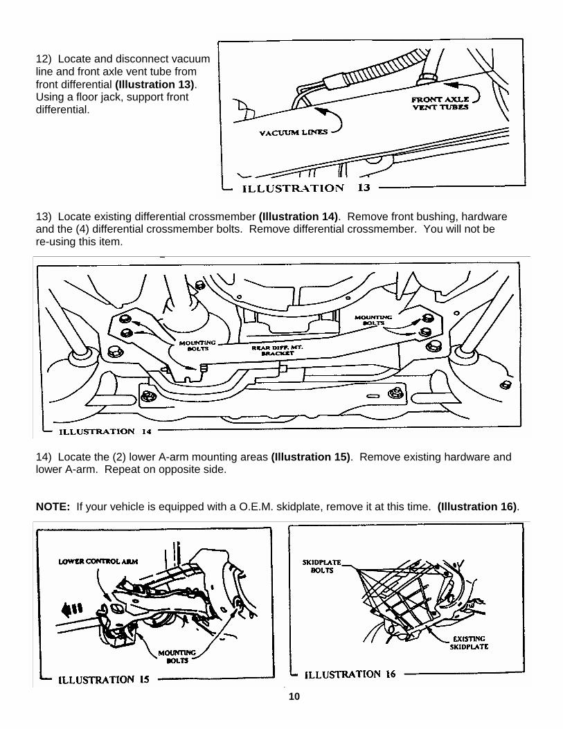
12) Locate and disconnect vacuum line and front axle vent tube from front differential (Illustration 13). Using a floor jack, support front differential.
13) Locate existing differential crossmember (Illustration 14). Remove front bushing, hardware and the (4) differential crossmember bolts. Remove differential crossmember. You will not be re-using this item.
14) Locate the (2) lower A-arm mounting areas (Illustration 15). Remove existing hardware and lower A-arm. Repeat on opposite side.
NOTE: If your vehicle is equipped with a O.E.M. skidplate, remove it at this time. (Illustration 16).

11
FRONT INSTALLATION
1) Making sure that front differential is well supported, remove existing hardware from both passenger and driver side differential mounting areas. Carefully lower differential enough to install differential drop bracket (90-1463) on passenger side (Illustration 17) using the 1/2” hardware provided. Install but do not tighten.
2) Install front driver side differential drop bracket (90-1463) (Illustration 18) using 12mm hardware provided. Make sure that the head of the bolt is located to the driver outboard side of the vehicle. Do not tighten.

12
3) Install rear crossmember (90-1460) into original A-arm rear mounting locations (Illustration 19). Make sure differential mount sets into mounting tabs on rear crossmember (Illustration 20). Fasten using existing hardware previously removed. Make sure that the bolt heads are facing towards rear of vehicle. Do not tighten.
4) Install front crossmember (90-1402) (Illustration 19) into original front A-arm mounting locations. Unfasten and slide driver side lower differential mounting hardware back enough to align differential mount bracket with support tab on crossmember (Illustration 22). Fasten front crossmember, using existing hardware previously removed. Make sure that heads of the bolts are facing to the rear of vehicle. Do not tighten.
13
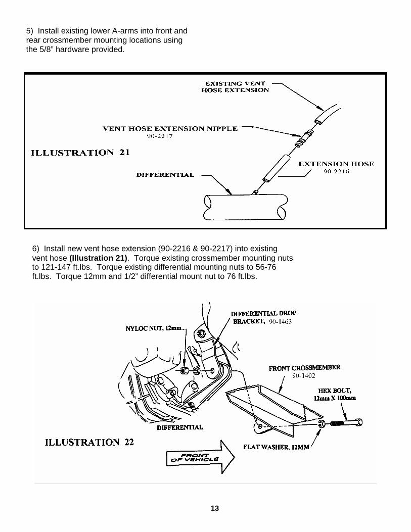
5) Install existing lower A-arms into front and rear crossmember mounting locations using the 5/8” hardware provided.
6) Install new vent hose extension (90-2216 & 90-2217) into existing vent hose (Illustration 21). Torque existing crossmember mounting nuts to 121-147 ft.lbs. Torque existing differential mounting nuts to 56-76 ft.lbs. Torque 12mm and 1/2” differential mount nut to 76 ft.lbs.

14
7) Referring to Illustration 23 install crossmember support brackets (90-1461 driver) and (90-1462 passenger). Temporary fasten the upper mounts of brackets to existing rear crossmember mounting locations, using hardware previously removed. And lower mounts to rear crossmember using 7/16” hardware provided. Do not tighten at this time.
8) Install front crossmember spacer (90-2215) using 1/2” hardware and load washer (Illustration 24). Make sure bolt head is on the bottom. Torque nut to 76 ft.lbs.

15
9) Remove seals from old spindles and install in new spindles. Support lower A-arms. Position new front spindles (90-4025 driver) and (90-4024 passenger) (Illustration 25). Attach spindle to upper ball joint. Torque nut to 57-77 ft.lbs. Attach ball joint on lower A-arm to front spindle. Torque to 83-112 ft.lbs. Apply new cotter pins at these locations. Install axle bearing assembly, apply loctite and torque the three bolts to 110-148 ft.lbs. Do not tighten hub nut at this time.

16
10) Attach Tie-Rods to Front Spindle, making sure tapers are seated. Torque existing nuts to 57-77 ft.lbs. Apply new cotter pins at these locations. Install front disc brake rotor shield, (referring back to Illustration 5) using existing hardware. Do not over tighten.
11) Re-install Sway Bar using Sway Bar Link (90-2089) and hardware provided (Illustration 26). Torque nuts to 16-21 ft.lbs.
17
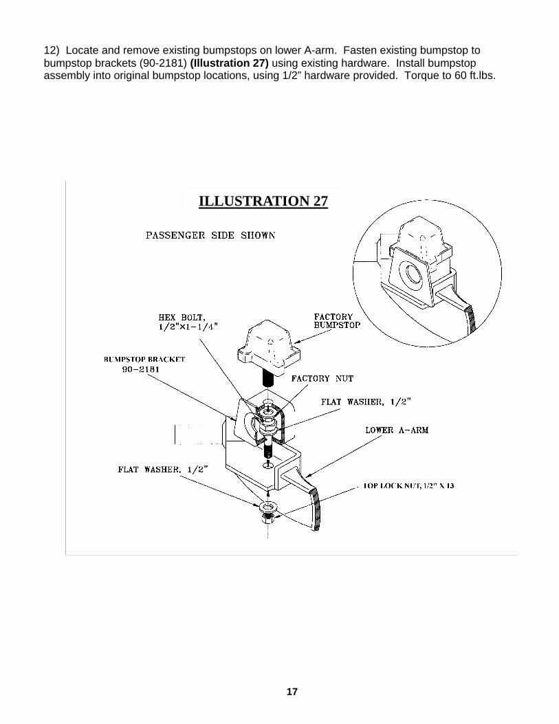
12) Locate and remove existing bumpstops on lower A-arm. Fasten existing bumpstop to bumpstop brackets (90-2181) (Illustration 27) using existing hardware. Install bumpstop assembly into original bumpstop locations, using 1/2” hardware provided. Torque to 60 ft.lbs.
ILLUSTRATION 27

18
13) Locate existing torsion bar crossmember mount bracket. Remove nut clip and rubber mounting bushing, drill out center mounting hole on bracket to 1/2” diameter. Be sure to turn the mounting bracket over before installing. Slide the bracket onto torsion bar crossmember, then insert Torsion Bar Spacer (90-2110) (Illustration 28). Loosely fasten using Torsion Bar Drop Bracket (90-4032) provided as shown in Illustration 28. Insert existing Torsion Bars, then torque hardware to specification chart on back page. Set the torsion bar adjuster screw to depth previously set in Instruction 1.
15) Install front disc brake rotors (referring back to Illustration 4), but do not tighten hub nut at this time.
14) Install new longer front shock absorbers (Pro-Comp 320510). Torque according to specification chart on last page.
ILLUSTRATION 28
HEX BOLT 1/2” X 5” LG.
HEX BOLT 1/2” X 4” LG.

19
ILLUSTRATION 29 90-1540
1/2” x 4”
90-1512
90-1541
90-1104
1/2” x 1-1/4”
15-11148
90-2109
90-2218
90-2218
90-1104
FRONT OF VEHICLE
16) Support Transmission using floor jack. Locate and remove existing rear transmission crossmember (you will not be re-using this item). Loosely install Trans Crossmember (90-1512) as shown in Illustration 29, using existing hardware previously removed. Next loosely assemble the Trans Crossmember Mount (90-1540) Driver (90-1541) Passenger to Trans Crossmember and existing vehicle frame as shown. Install all 1/2” x 1-1/4” bolts with washer and nuts but do not tighten. Use the existing transmission crossmember bolt to secure the new crossmember to the frame on both sides. Torque all 1/2” hardware to 70 ft.lbs., except the two bolts that secure the 90-1104 Compression Strut Mounts (See detail in Illustration 29). Install the 90-1104 Compression Strut Mounts.
3/8” x 1”
3/8” x 1”
17) Assemble Compression Struts (90-2218) using Bushings (15-11148) and Sleeves (90-2109). Remove driver side Crossmember Support Bracket (90-1461). Position compression struts as shown in Illustration 29, install using the 1/2” hardware provided. Reinstall the crossmember support bracket to crossmember and existing mount. Torque existing trans crossmember nuts to 64-81 ft.lbs. Torque 1/2” nuts to 70 ft.lbs. Secure the exhaust shield to the new crossmember with the 3/8” x 1” bolts, washers and split lockwashers. Torque to 18 ft.lbs.
20
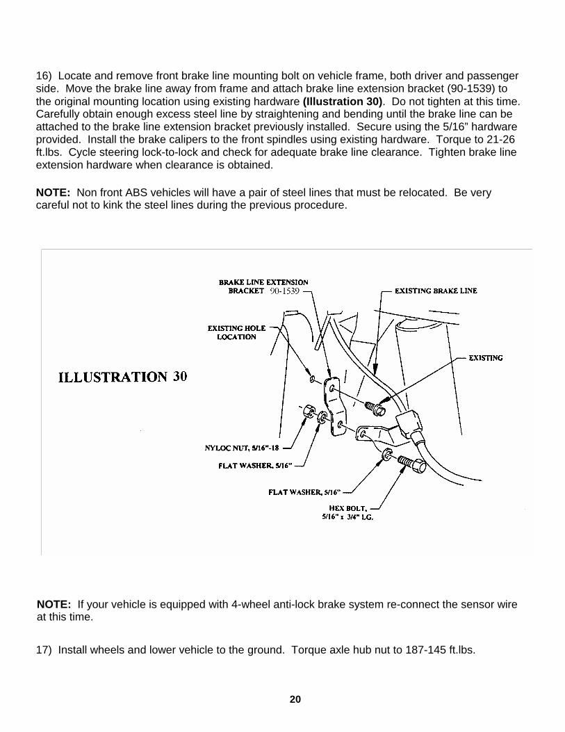
16) Locate and remove front brake line mounting bolt on vehicle frame, both driver and passenger side. Move the brake line away from frame and attach brake line extension bracket (90-1539) to the original mounting location using existing hardware (Illustration 30). Do not tighten at this time. Carefully obtain enough excess steel line by straightening and bending until the brake line can be attached to the brake line extension bracket previously installed. Secure using the 5/16” hardware provided. Install the brake calipers to the front spindles using existing hardware. Torque to 21-26 ft.lbs. Cycle steering lock-to-lock and check for adequate brake line clearance. Tighten brake line extension hardware when clearance is obtained.
NOTE: Non front ABS vehicles will have a pair of steel lines that must be relocated. Be very careful not to kink the steel lines during the previous procedure.
17) Install wheels and lower vehicle to the ground. Torque axle hub nut to 187-145 ft.lbs.
NOTE: If your vehicle is equipped with 4-wheel anti-lock brake system re-connect the sensor wire at this time.

REAR INSTALLATION
21
• To install your Add-A-Leaf (13132-1) properly you must use (2) large c-clamps or a large vise to contain the elastic potential energy stored in a leaf spring when the center bolt is removed.
• Your new Add-A-Leaf will be placed in the spring assembly in a progressive pyramid shape.
• EXAMPLE: If our leaf #1 is 32” long and your leaf #2 is 25” long and the new Add-A-Leaf is 28” long, place the Add-A-Leaf between leaves #1 and #2.
• Some springs will have a factory helper spring consisting of flat or nearly flat leaves installed at the bottom of the leaf pack (Illustration 31). Do not install your Add-A-Leaf spring in or below the helper spring assembly.
1) Raise the rear of the vehicle, support the frame with jackstands and remove the rear wheels.
2) With a floor jack, raise the rear axle enough to relieve the tension on the shock absorbers and remove them. Disconnect the axle vent hose from the axle housing.
3) Making sure the axle is well supported, remove the axle U-bolts and hardware. Now remove the spring eye bolts and/or shackles and remove the springs from the vehicle.
4) Using c-clamps or a large bench vise, hold the spring assembly securely together.
5) If applicable, remove any spring leaf alignment clamps. Using vise-grips to hold the head of the center bolt, loosen and remove it. If the bolt has rusted, a hammer and a drift punch may be used to drive it out.
22
6) Carefully remove c-clamps or open vise and lay unassembled spring aside.
7) With a small amount of grease applied to both ends of the Add-A-Leaf (13132-1), re-assemble leaf springs with Add-A-Leaf in place.
8) Loosely assemble the completed spring assemblies into their respective chassis mounts. Install provided U-bolts and hardware. Torque all hardware according to the factory specifications.
9) Re-connect axle vent hose and install the longer rear shock absorbers (329510) and torque according to the specification chart on the last page.
10) Install wheels and lower to ground.
SOME FINAL NOTES:
• After installation is complete, double check that all nuts and bolts are tight. Refer to the chart on the last page for torque specifications. (Do not retighten nuts and bolts where loctite compound was applied.)
• If new tires are installed that are more than 10% taller than original tires, the speedometer must be recalibrated for the anti-lock brake system (if applicable) to function properly. Contact an authorized Ford dealer for details on recalibration.
• Bleed brake system according to O.E. specifications (only if hoses were changed). Use Ford approved brake fluid only.
• With vehicle on floor, cycle steering lock-to-lock and inspect steering, suspension and driveline systems for proper operation, tightness and adequate clearance. Recheck brake/hose fitting for leaks. Be sure all hoses are long enough.
• Have headlights readjusted to proper setting.
• Realign front end to factory specifications. Be sure vehicle is at desired ride height prior to realignment.

23
Notice to Owner operator, Dealer and Installer: Vehicles that have been enhanced for off-road performance often have unique handling characteristics due to
the higher center of gravity and larger tires. This vehicle may handle, react and stop differently than many passen-ger cars or unmodified vehicles, both on and off–road. You must drive your vehicle safely! Extreme care should always be taken to prevent vehicle rollover or loss of control, which can result in serious injury or even death. Al-ways avoid sudden sharp turns or abrupt maneuvers and allow more time and distance for braking! Pro Comp re-minds you to fasten your seat belts at all times and reduce speed! We will gladly answer any questions concerning the design, function, maintenance and correct use of our products.
Please make sure your Dealer/Installer explains and delivers all warning notices, warranty
forms and instruction sheets included with Pro Comp product. Application listings in this catalog have been carefully fit checked for each model and year denoted. How-
ever, Pro Comp reserves the right to update as necessary, without notice, and will not be held responsible for mis-prints, changes or variations made by vehicle manufacturers. Please call when in question regarding new model year, vehicles not listed by specific body or chassis styles or vehicles not originally distributed in the USA.
Please note that certain mechanical aspects of any suspension lift product may accelerate or-
dinary wear of original equipment components. Further, installation of certain Pro Comp products may void the vehicle’s factory warranty as it pertains to certain covered parts; it is the consumer’s responsibility to check with their local dealer for warranty coverage before installation of the lift.
Warranty and Return policy: Pro Comp warranties its full line of products to be free from defects in workmanship and materials. Pro
Comp’s obligation under this warranty is limited to repair or replacement, at Pro Comp’s option, of the defective product. Any and all costs of removal, installation, freight or incidental or consequential damages are expressly excluded from this warranty. Pro Comp is not responsible for damages and / or warranty of other vehicle parts re-lated or non-related to the installation of Pro Comp product. A consumer who makes the decision to modify his vehicle with aftermarket components of any kind will assume all risk and responsibility for potential damages in-curred as a result of their chosen modifications. Warranty coverage does not include consumer opinions regarding ride comfort, fitment and design. Warranty claims can be made directly with Pro Comp or at any factory author-ized Pro Comp dealer.
IMPORTANT! To validate the warranty on this purchase please be sure to mail in the warranty card. Claims not covered under warranty- • Parts subject to normal wear, this includes bushings, bump stops, ball joints, tie rod ends and heim joints • Discontinued products at Pro Comp’s discretion • Bent or dented product • Finish after 90 days • Leaf or coil springs used without proper bump stops • Light bulbs • Products with evident damage caused by abrasion or contact with other items • Damage caused as a result of not following recommendations or requirements called out in the installation manuals • Products used in applications other than listed in Pro Comp’s catalog • Components or accessories used in conjunction with other manufacturer’s systems • Tire & Wheel Warranty as per Pro Competition Tire Company policy • Warranty claims without “Proof of Purchase” • Pro Comp Pro Runner coil over shocks are considered a serviceable shock with a one-year warranty against leakage only. Rebuild service and replacement parts will be available and sold separately by Pro Comp. Contact Pro Comp for specific service charges. • Pro Comp accepts no responsibility for any altered product, improper installation, lack of or improper maintenance, or improper use of our products.
E-Mail: [email protected] Website: www.explorerprocomp.com Fax: (619) 216-1474 Ph: (619) 216-1444
HERE: __________________
WARRANTY REGISTRATION NUMBER
PLACE