Embed Size (px)
Citation preview

1
51802 Revised
5.31.2014
PRO COMP SUSPENSION
This document contains very important information that includes warranty information and instructions for resolving problems you may encounter. Please keep it in the vehicle as a permanent record.
IMPORTANT!: This kit cannot be used in conjunction with Factory wheels.
51802B/51802BP K1085B/K1085BP 2011-2015 Silverado 2500 HD 2wd/4wd 6” Lift Kit
51802B/51802BP K1087B/K1087BP 2011-2015 Silverado 3500 HD 2wd/4wd 6” Lift Kit w/ 50350B Rear U-Bolt Kit
Latest Revision: 5.31.2014
400 W. Artesia Blvd. Compton, CA 90220 Fax: (310) 747-3912 Ph: 1-800-776-0767 E-Mail: [email protected] Website: www.procompusa.com
51802B/51802BP K1088B/K1088BP 2011-2015 Silverado 3500 HD and DRW 2wd/4wd 6” Lift Kit w/ 50351B Rear U-Bolt Kit

2
51802 Revised
5.31.2014
Part # Description Qty. Illus. Page Box 1 of 4-PN 51802B-1
91-7132 REAR CROSSMEMBER 1 4,6 9,10 90-6783 HARDWARE PACK: Crossmember 1 - - .180C1200HCS1Z 18mm-2.5 X 120mm HEX BOLT GR 10.9 2 10 13 .180C1400HCS1Z 18mm-2.5 X 140mm HEX BOLTGR 10.9 2 10 13 .180CNUCZ 18mm-2.5 STOVER NUT GR. C 4 10 13 .180NWUSZ 18mm USS FLAT WASHER 8 10 13 91-7131 DIFFERENTIAL SKID PLATE: 4WD 1 6 10 90-6790 HARDWARE PACK: Skid Plate 1 - - 94850A170 3/8" NO-SLIP CLIP ON NUTS 2 6 10 37C100HCS8Y 3/8” X 1" HEX CAP SCREW GR. 8 6 6 10 37NWHDY/SAE 3/8” HARDENED FLAT WASHER 6 6 10 90-4331 CV AXLE SHAFT SPACER 2 7 10 90-6786 HARDWARE PACK: Axle Shaft Spacers 1 - - .100C450HCS1Y 10mm-1.5 X 45mm HEX BOLT GRADE 10.9 16 7 10 .100NWHDY 10mm HARDENED FLAT WASHER 16 7 10 91-7094 DIFF DROP: Drvr 1 3 8 91-7098 DIFF DROP: Pass 1 3 8 90-6784 HARDWARE PACK: Diff Drop 1 - - 120C300HCS1Y 12mm-1.75 X 30mm HEX BOLT GR. 10.9 3 3 8 .120NWHDY 12mm HARDENED FLAT WASHER 3 3 8 50C150HCS8Y 1/2” X 1 1/2” HEX BOLT GR. 8 2 3 8 50C350HCS8Y 1/2” X 3 1/2” HEX BOLT GR. 8 3 3 8 50CNUCZ 1/2” STOVER NUT GR. C 5 3 8 50NWHDY/SAE 1/2” HARDENED FLAT WASHER 10 3 8 91-7088 REAR BRAKE LINE DROP 1 12 16 90-6789 HARDWARE PACK: Rear Brake Line Drop/Rad Bracket 2 - - 31C75HCS8Y 5/16” X 3/4” HEX BOLT GR 8 1 12 16 31CNUCZ 5/16” STOVER NUT GR. C 1 12 16 31NWHDY/SAE 5/16” HARDENED FLAT WASHER 2 12 16 90-6787 HARDWARE PACK: Rear Bump Stop Pad Spacer 1 - - .80C200HCS1Y 8mm-1.25 X 20mm HEX BOLT GR 10.9 2 11,12 15,16 91-7090 REAR BUMPSTOP PAD SPACER 2 11,12 15,16 95-308 3" REAR LIFT BLOCK 2 11,12 15,16 13-90348 U-BOLT: 2500 ONLY!: 3/4"-16 X 3.145" X 15.250" 4 12 16 20-65750 HARDWARE PACK: Hi– Nut 1 - - 3/4”-16 HIGH NUT 8 12 16 3/4” HARDENED FLAT WASHER 8 12 16 90-7146 EMERGENCY BRAKE CABLE SUPPORT 1 12 16

3
51802 Revised
5.31.2014
Part # Description Qty. Illus. Page 90-6791 HARDWARE BAG: ABS Relocation Bracket 1 - - 90-7147 ABS RELOCATION BRACKET 2 12 16 90-6299 HARDWARE PACK: ABS Relocation Bracket 1 - - 70-0311001500 5/16” X 1” GR.5 HEX BOLT 2 12 16 72-03100100512 5/16” NYLOCK NUT 2 12 16
73-03100030 5/16” SAE FLAT WASHER 4 12 16
91-7130 RADIATOR HOSE BRACKET 1 - - 90-7113 FRONT BUMP STOP LOCKING TAB 2 8 11 91-8133 FRONT BUMP STOP SPACER: Drvr 1 8 11 91-8135 FRONT BUMP STOP SPACER: Pass 1 8 11 91-7120 FRONT BUMP STOP SUPPORT PLATE 2 8 11 91-7145 DIFFERENTIAL SKID PLATE MOUNT: 2WD 1 - - 90-6502 HARDWARE PACK: Front Bump Stop 1 - - 50C125HCS8Y 1/2” X 1 1/4” HEX BOLT GR. 8 2 8 11 50NWHDY/SAE 1/2” HARDENED FLAT WASHER 2 8 11 90-6513 HARDWARE PACK: Front Bump Stop 1 - - 31C100HCS8Y 5/16” X 1” HEX BOLT GR 8 4 8 11 31CNUCY 5/16” STOVER NUT GR. C 4 8 11 31NWHDY/SAE 5/16” HARDENED FLAT WASHER 8 8 11
90-4328 KNUCKLE: Drvr 1 - - 90-4329 KNUCKLE: Pass 1 - - 90-6782 HARDWARE PACK: Spare Tire Spacer 1 - - 90-7089 WHEEL SPACER 1 - -
Box 2 of 4-PN 51802B-2
Box 3 of 4-PN 51802B-3
91-7123 FRONT CROSSMEMBER 1 5,6 9,10 91-7101 TORSION BAR DROP: Drvr 1 9 12 91-7105 TORSION BAR DROP: Pass 1 9 12 90-6785 HARDWARE PACK: Torsion Bar Drop 1 - - 56C375HCS8Y 9/16” X 3 3/4 HEX BOLT GR 8 2 9 12 56CNUCZ 9/16” STOVER NUT GR. C 2 9 12 56NWHDY/SAE 9/16” HARDENED FLAT WASHER 4 9 12 90096A542 1/4"-20 X 1" SELF TAPPING HEX BOLT 2 9 12 1/4" SAE FLAT WASHERS 4 9 12 1/4" SLIT LOCK WASHERS 2 9 12 1/4" HEX NUT PLATED (non locking) 2 9 12 90-7141 DUAL NUT PLATE: Rear Crossmember 1 3 8

4
51802 Revised
5.31.2014
Part # Description Qty. Illus. Page
924375 9000 SERIES FRONT SHOCKS 2 - - 930001 9000 SERIES REAR SHOCKS 2 - -
Box 4 of 4-PN 51802B-4
90-6339 HARDWARE PACK: Dual Nut Plate: Rear Xmember 1 - - 43C100HCS8Y 7/16” X 1” HEX BOLT GR. 8 2 3 8 43NWSAZ 7/16” SAE FLAT WASHER 2 3 8 43CNUCZ 7/16” STOVER NUT GR. C 2 3 8 43NWHDY/USS 7/16” HARDENED USS FLAT WASHER 2 3 8 90-6788 HARDWARE PACK: Sway Bar End Link 1 - - 90-7122 WASHER 6 10 13 90-8136 OUTER TUBE 2 10 13 13-90420 STUD 3/8”-24 x 14.50" 2 10 13 72-03700200512 3/8" SAE NYLOCK NUT- FINE THREAD 4 10 13 90-6793 HARDWARE PACK: FRONT BRAKE LINE 1 - - 90-5578 BRAKE LINE BRACKET 2 10 13 90-6299 HARDWARE PACK: ABS Relocation Bracket 1 - - 70-0311001500 5/16” X 1” GR.5 HEX BOLT 2 10 13 72-03100100512 5/16” NYLOCK NUT 2 10 13 73-03100030 5/16” SAE FLAT WASHER 4 10 13 90-6870 HARDWARE PACK: Diff Mount 1 - - 90-7875 DIFFERENTIAL MOUNT SHIMS 6 - - 90-6871 HARDWARE PACK: ABS Bracket 1 - - 56C450HCS8Y 9/16” X 4 1/2” HEX BOLT Gr. 8 2 - - 56NWHDY/SAE 9/16” SAE HARDENED FLAT WASHER 4 - - 56CNUCZ 9/16” STOVER NUT 2 - -
13-90350 U-BOLT: 3500: 3/4"-16 X 3.080" X 16.250 4 12 16 20-65750 HARDWARE PACK: Hi Nuts 1 - - HI NUTS: 3/4” 8 12 16
FLAT WASHERS 8 12 16
50350B: 3500 U-Bolt Kit * Kit Dependant
13-90351 U-BOLT: 3500 w/ dual wheel : 3/4"-16 X 3.080" X 17.50 4 12 16 20-65750 HARDWARE PACK: Hi Nuts 1 - - HI NUTS: 3/4” 8 12 16
FLAT WASHERS 8 12 16
50351B: 3500 DRW U-Bolt Kit * Kit Dependant
ZX2030 PRO RUNNER MONOTUBE FRONT SHOCKS 2 - - ZX2031 PRO RUNNER MONOTUBE REAR SHOCKS 2 - -
Box 4 of 4-PN 51802BP-4

5
51802 Revised
5.31.2014
71201B: TRACTION BAR MOUNTING KIT 72500B: TUBE TRACTION BAR KIT (must be used with kit 71201) 72502B: PLATE TRACTION BAR KIT (must be used with kit 71201)
50350B: 3500 Rear U-Bolt Kit 50351B: 3500 DRW Rear U-Bolt Kit
Lights: Call for Application
Also, Check out our outstanding selection of tires to compliment your new installation!
Equipment Available from your Pro Comp Distributor!
Wheel and Tire Information:
IMPORTANT!: This kit cannot be used in conjunction with Factory wheels or the factory spare on the front suspension
Due to differences in manufacturing, dimensions and inflated measurements, tire and wheel combinations should be test fit prior to installation. Tire and wheel choice is crucial in assuring proper fit, performance, and the safety of your Pro Comp equipped vehicle. For this application, we recommend a 17” wheel not to exceed 9” in width with a maximum backspacing of 5 1/2” can be used. An 18” wheel not to exceed 9” in width with a maximum backspacing of 5 3/4” can be used. Also a 20” wheel not to exceed 9” in width with a maximum backspacing of 6 1/8” can be used. A quality tire of radial design, not exceeding 35” tall X 12.5” wide is also recommended. Please note that the use of a 35” X 12.5” tire may re-quire trimming of the front valence. Violation of these recommendations will not be endorsed as acceptable by Pro Comp Suspension and will void any and all warranties either written or implied.
Warning! Be extremely careful when unloading or loading the torsion bars on your vehicle.
There is a tremendous amount of stored energy! Keep your hands and body clear of the adjuster arm assembly and puller tool in case anything slips or breaks!
A special removal tool is required for safe removal and installation of the torsion adjuster arms. This special puller can be purchased from Pro Comp (PN 67965). Call for details.
Front end and head light realignment is necessary!
Speedometer and ABS recalibration will be necessary if larger tires (10% more than stock diame-ter) are installed
Special Equipment

6
51802 Revised
5.31.2014
This installation requires a professional mechanic!
We recommend that you have access to a GM service manual for your vehicle to assist in the disassembly and reassembly of your vehicle. It contains a wealth of detailed information.
Prior to installation, carefully inspect the vehicle’s steering and driveline systems paying close attention to the tie rod ends, ball joints, wheel bearing preload, pitman and idler arm. Additionally, check steering-to-frame and suspension-to-frame attaching points for stress cracks. The overall vehicle must be in excellent working condition. Repair or replace all worn or damaged parts!
Read the instructions carefully and study the illustrations before attempting installation! You may save your-self a lot of extra work.
Check the parts and hardware against the parts list to assure that your kit is complete. Separating parts ac-cording to the areas where they will be used and placing the hardware with the brackets before you begin will save installation time.
Check the special equipment list and ensure the availability of these tools.
Secure and properly block vehicle prior to beginning installation.
ALWAYS wear safety glasses when using power tools or working under the vehicle!
Use caution when cutting is required under the vehicle. The factory undercoating is flammable. Take appro-priate precautions. Have a fire extinguisher close at hand.
Foot pound torque readings are listed on the Torque Specifications chart at the end of the instructions. These are to be used unless specifically directed otherwise. Apply Loctite® retaining compound where specified.
Please note that while every effort is made to ensure that the installation of your Pro Comp lift kit is a positive experience, variations in construction and assembly in the vehicle manufacturing process will virtually ensure that some parts may seem difficult to install. The use of pry bars and tapered punches for alignment is considered normal and usually does not indicate a faulty product. However, if you are uncertain about some aspect of the installation process, please feel free to call our tech support department at the number listed on the cover page. We do not recommend that you modify the Pro Comp parts in any way as this will void any warranty expressed or implied by the Pro Comp Suspension company.
No special driveshaft is required with this kit. Vehicles with a one piece rear driveshaft may ex-perience driveline vibration.
This kit does not work on vehicles with rear steering.
This kit will not work on vehicles equipped with factory electronic or air ride suspension systems.
This system is designed to fit both 2wd and 4wd vehicles. On any 2wd installations disregard any steps involving the front differential and the C.V. shafts.
Verify the differential fluid is at the manufacturers recommended level prior to the installation of the kit. The installation of this kit will reposition the differential and the fill plug hole may be in a different position. (For example, if the manufacturer recommends 3 quarts of fluid, make sure the differential has 3 quarts of fluid). Check your specific manual for the correct amount of fluid.
Introduction:

7
51802 Revised
5.31.2014
Front Installation 1. Ensure that your work space is of adequate
size and the work surface is level. Measure and record the distance from the center of each wheel to the top of its fender opening.
2. Place the vehicle in neutral. Place your floor jack under the front cross member and raise vehicle. Place jack stands under the frame rails behind the front wheel wells and lower the frame onto the stands. Remove the jack and place the vehicle back in gear, set the emergency brake, and place blocks both in front and behind the rear wheels.
3. Remove any skid plates or debris shields from the vehicle. Save the hardware for reinstalla-tion.
4. Unbolt the sway bar end links from the sway bar and lower control arms. Save the hardware for reinstallation.
5. Carefully remove the (4) OE rubber bump stops. Save for reinstallation.
6. Remove the front shock absorbers from the vehicle. Save hardware for reinstallation.
7. Measure the torsion bar adjusting screw depth and record this dimension for later use on reas-sembly. See ILLUSTRATION 1.
8. Remove the torsion bar adjusting screw. Ap-ply a small amount of lubrication grease to the puller threads and the puller shaft-to-adjuster arm contact point. Load the puller and torsion adjuster arm until the adjuster nut can be re-moved from the cross member. Release the puller to unload the torsion bar. With the bar unloaded, slide it forward into the lower con-trol arm until the adjuster arm falls free. NOTE: If the bar seems stuck, use a ham-mer and punch through the hole in the rear
of the cross member to dislodge it.
9. Repeat this procedure on the other side of the vehicle.
10. Remove the ABS wires and heat shield from the torsion bar crossmember. Save for rein-stallation.
11. Remove the torsion bar crossmember by un-bolting it from the frame.
12. Remove the torsion bars from the lower A-arms.
13. Disconnect the ABS sensor from the frame.
14. Unbolt the brake line bracket from the frame. Save the hardware for reuse.
15. Remove the brake line bracket from the top of the OE knuckle. Unplug the ABS brake con-nection from the frame and control arm.
CAUTION!: Do not suspend the calipers by the brake lines! Damage will result!
16. Remove the brake caliper from the rotor and secure them clear of the work area. Secure the caliper up with wire so they do not hang.
17. Remove the front rotor from the front hub.
18. Remove the CV axle retaining nut.
LR: RR:
RF: LF:
LEFT: RIGHT:
See Special Equipment Notice on Page 3.
Measure & Save Dimensions
Before Disassembly!
Illustration 1 Torsion Bar Unloading
Front

8
51802 Revised
5.31.2014
19. Unbolt the (4) bolts holding the hub flange to the knuckle. Remove the hub and O-ring and save for reinstallation.
20. Remove the nut from the OE tie rod end. Us-ing an appropriate removal tool, remove the tie rod end from the knuckle.
21. Support the knuckle and loosen the upper ball joint nut from the knuckle. Separate using the appropriate tool.
22. Support the knuckle and loosen the lower ball joint nut from the knuckle. Separate using the appropriate tool.
23. Remove the (8) retaining bolts from each CV joint. Carefully remove the CV axle from the side of the vehicle you are currently working on. NOTE: Be extra cautious with the CV boots. DO NOT damage them!
24. Support the lower A-arm with your floor jack and remove the upper and lower ball joint nuts. Remove the knuckle from the vehicle.
25. Support the lower A-arm with your floor jack and remove the lower A-arm pivot bolts. Carefully remove the lower A-arms from the vehicle.
26. Disconnect the front drive shaft from the front differential and secure it clear of the work area. Tape the U-joint caps in place.
27. Disconnect the differential vent line and any electrical control wire harnesses that may be present. Secure these clear of the work area.
28. Remove the OE differential rear crossmember and discard. Save the hardware or reinstalla-tion.
Illustration 2 Driver side Frame Cut
Driver side OE rear A-arm Pocket
Front
OE Diff Studs
OE Diff nuts
1/2” X 1 1/2” Bolts
12mm X 30mm Bolts
(2) 1/2” X 3 1/2” Bolts
1/2” Nut
1/2” X 3 1/2” Bolts
90-7141 Dual Nut Plate
Access Hole for Nut Plate in Frame
OE Diff Mount Bracket
Front
Front
Illustration 3 Differential Installation

9
51802 Revised
5.31.2014
29. Support the differential with your floor jack. Unbolt and lower the differential to the ground and move it clear of the work area.
30. On the Driver Side ONLY!, using a suitable cutting tool, (abrasive cutoff wheel, Sawz-all, etc.) cut the rear A-arm mounting pocket as shown in ILLUSTRATION 2. Measure in to-ward the center of the vehicle .625” from the center of the OE a-arm bolt hole and make a vertical cut. Follow the dimensions shown closely!
31. After cutting the frame pocket, clean the area thoroughly and paint the exposed metal with a good quality paint.
32. Install the driver side differential bracket (91-7094) to the bottom of the OE frame mount. Secure the front (2) bolt holes using the sup-plied 12mm X 30mm bolts. Secure the rear bolt hole by inserting the (1) 1/2” X 3 1/2” bolt and hardware from the top of the OE diff
bracket. See ILLUSTRATION 3.
33. Install the passenger side differential bracket (91-7098) to the bottom of the OE frame mounting studs using the previously removed OE nuts. See ILLUSTRATION 3.
34. Carefully raise the differential into position and secure it to the driver side drop bracket using the supplied 1/2” X 3 1/2” bolts and hardware in the front (2) holes and the 12mm X 30mm bolt and hardware in the rear hole. See ILLUSTRATION 3.
35. Secure the differential to the passenger side drop bracket using the (2) supplied 1/2” X 1 1/2” bolts and hardware. See ILLUSTRA-TION 3.
36. Install the rear crossmember (91-7132) into the factory lower control arm pockets using the (4)previously removed OE bolts and hardware. Install the bolts with the heads to the rear of the vehicle. Leave loose at this time. See IL-LUSTRATION 4.
37. Install the front crossmember (91-7123) into the factory lower control arm pockets using the previously removed OE bolts and hardware. Install the bolts with the heads to the front of the vehicle. Leave loose at this time. See IL-LUSTRATION 5.
91-7123 Front Crossmember
OE Bolts
Illustration 5 Front Crossmember
Front
OE Bolts
7/16” X 1 1/4” Bolt
OE Bump Stop OE Bump Stop
91-7132 Rear Crossmember
OE Bolt
Illustration 4 Rear Crossmember

10
51802 Revised
5.31.2014
38. On the Driver Side ONLY!, install the rear crossmember dual nut plate (90-7141) through the hole in the frame revealed from the previ-ous frame cutting. See ILLUSTRATION 3 & 4.
39. Secure the rear crossmember to the rear cross-member nut plate using the (2) supplied 7/16” X 1” bolts and hardware from pack (90-6339). See ILLUSTRATION 4.
40. Reinstall the vent tube and the electronic wir-ing to the differential. You may have to re-route these for proper fit.
41. Install the lower control arm into the new crossmember mounting pockets. Secure using the 18mm X 120mm (front) and 18mm X
140mm (rear) bolts and 18mm hardware. Do not torque the bolts until the vehicle is on the ground. See ILLUSTRATION 10.
42. 4WD MODELS ONLY!: Install the (2) no-slip clip on nuts (94850A170) onto the front differ-ential skid plate (91-7131). Secure the differ-ential skid plate (91-7131) to the front and rear crossmember mounting holes using the sup-plied 3/8” X 1” bolts and hardware. See IL-LUSTRATION 6.
43. 2WD MODELS ONLY!: Install the (2) no-slip clip on nuts (94850A170) onto the front differ-ential skid plate mount (91-7145). Secure the differential skid plate mount (91-7145) to the front crossmember mounting holes using the supplied 3/8” X 1” bolts and hardware. See ILLUSTRATION 6.
44. Torque the following differential and cross-member bolts: The driver side 1/2” differential bolts to 70 ft./lbs and the 12mm bolts to 65 ft./lbs. The passenger side 1/2” differential bolts to 70 ft./bolt and the OE nuts to manufacturers specifications. The OE crossmember bolts to OE specifications. The front differential skid plate/mount 3/8” bolts to 25 ft./lbs. Recheck all bolts on the front end for proper torque be-fore proceeding to next step.
45. Assemble the new steering knuckles (90-4328 drvr and 90-4329 pass) using the previously removed OE hub bearing assemblies and O-rings. Apply thread lock compound to the OE hardware. Torque the flange bolts to 130 ft./lbs. NOTE: Be sure the O-ring is placed in it’s proper position while installing the hub.
46. Install the assembled knuckle to the upper and lower ball joints using the OE nuts. Torque the upper ball joint to 35 ft./lbs. and the lower ball joint to 70 ft./lbs.
47. Turn the tie rod ends 180 degrees. Reattach the tie rod end to the new knuckle using the previously removed OE nuts. Torque the fac-tory nut to 30 ft./lbs.
48. Insert the CV shaft into the steering knuckle
Illustration 7 CV Axle Spacer
10mm X 45mm Bolts
90-4331 CV Spacer
Differential Flange
CV Axle Shaft
3/8” X 1 1/4” Bolts
Illustration 6 Diff Skid Plate Install
Front
91-7131 Differential Skid Plate
OE Skid Plate
No Slip Clip On Nuts

11
51802 Revised
5.31.2014
and reinstall the axle shaft washer and retain-ing nut. Be sure to use thread locker on the retaining nuts. Torque the axle nuts to 150 ft./lbs.
49. Place one of the CV spacers (90-4331) be-tween the front differential drive flange and the CV. Use the 10mm X 45mm bolts and washer provided in hardware pack (90-6786) through the CV and spacer and into the dif-
ferential drive flange. Be sure to use thread lock compound on the bolts. See ILLUS-TRATION 7. Torque the CV spacer bolts to 55 ft./lbs. in a criss-cross pattern.
50. Reinstall the brake rotor and brake caliper. Torque the caliper to the knuckles to 70 ft./lbs. using the previously removed OE hard-ware. Be sure to use thread locker on these bolts.
51. Attach the new brake line drop bracket (90-5578) to the existing hole in the frame using the previously removed OE bolt. Attach the OE brake line bracket to the new bracket (90-5578) using the 5/16 X 1” bolt and hardware provided. See ILLUSTRATION 10.
52. Slide the brake line clamp down and attach it to the top hole in the back of the steering knuckle using the previously removed OE bolt. Torque the bracket hardware to 10 ft./lbs.
53. Attach the ABS cables to the knuckles and upper control arm with zip ties. Check to make sure that the brake line and ABS line is routed as to allow full turning radius to the steering without tire or suspension component contact.
54. Reattach the driveshaft to the differential yoke using the previously removed OE hard-ware. Torque U-joint straps to 19 ft./lbs. IMPORTANT!: Be sure to use thread locker on these bolts.
55. Install the locking tab (90-7113) into the OE bump stop pocket. Secure using a 1/4 turn clockwise. See ILLUSTRATION 8.
56. Install the bump stop spacer (91-8133 drvr and 91-8135 pass) to the locking tab using the provided 1/2” X 1 1/4” bolts and hard-ware. Leave hardware loose at this time. See ILLUSTRATION 8. NOTE: Be sure to align the spine on the bump stop tube so the spine is facing inward toward the center of the vehicle.
57. Install the bump stop support plate (91-7120) to the holes in the frame. The “J” hooks will
90-7113 Locking Tab
Bump Stop Spacer (91-8133 drvr and 91-8135 pass
1/2” X 1 1/4” Bolt
OE Bump Stop
91-7120 Spine Support Plate
5/16” X 1” Bolts
OE Bump Stop Mount
Toward inside of vehicle
Illustration 8 Bump Stop Spacer
Front
12
51802 Revised
5.31.2014
lock into place. The support plate will be ori-ented toward the front of the car. See ILLUS-TRATION 8.
58. Using an awl, align the bump stop spine and the support plate (91-7120). Secure it using the supplied 5/16” X 1” bolts and hardware. See ILLUSTRATION 8. NOTE: The holes will not align up per-fectly. As you tighten the bolts it will put pressure on the “J” hooks.
59. Torque all bump stop hardware according to the torque chart on page 17.
60. Install the previously removed OE bump stops into the in the (4) new bump stop locations. See ILLUSTRATION 8.
61. Repeat the steps 10 through 60 on the remain-ing side of the vehicle.
62. Install the torsion bars into the front A-arms. Again, be very careful to install them with the same orientation that they were removed (i.e. left front to left front, right front to right front!).
63. Install the torsion bars into the OE torsion bar crossmember.
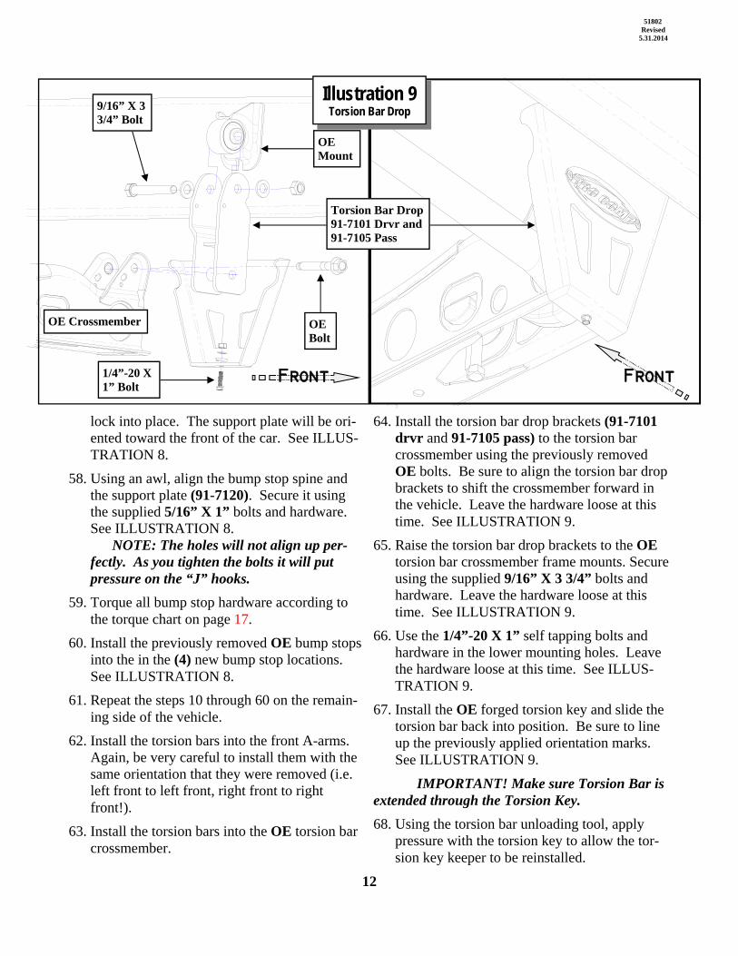
64. Install the torsion bar drop brackets (91-7101 drvr and 91-7105 pass) to the torsion bar crossmember using the previously removed OE bolts. Be sure to align the torsion bar drop brackets to shift the crossmember forward in the vehicle. Leave the hardware loose at this time. See ILLUSTRATION 9.
65. Raise the torsion bar drop brackets to the OE torsion bar crossmember frame mounts. Secure using the supplied 9/16” X 3 3/4” bolts and hardware. Leave the hardware loose at this time. See ILLUSTRATION 9.
66. Use the 1/4”-20 X 1” self tapping bolts and hardware in the lower mounting holes. Leave the hardware loose at this time. See ILLUS-TRATION 9.
67. Install the OE forged torsion key and slide the torsion bar back into position. Be sure to line up the previously applied orientation marks. See ILLUSTRATION 9.
IMPORTANT! Make sure Torsion Bar is extended through the Torsion Key.
68. Using the torsion bar unloading tool, apply pressure with the torsion key to allow the tor-sion key keeper to be reinstalled.
OE Bolt
9/16” X 3 3/4” Bolt
OE Mount
1/4”-20 X 1” Bolt
OE Crossmember
Torsion Bar Drop 91-7101 Drvr and 91-7105 Pass
Illustration 9 Torsion Bar Drop
Front Front

13
51802 Revised
5.31.2014
69. Reinstall the OE adjusting bolt to the torsion keeper and reset the torsion bar preload bolts using the measurements previously taken dur-ing disassembly. See ILLUSTRATION 9.
70. Torque the torsion bar drop hardware accord-ing to manufacturers specifications or to the torque chart on page 17.
71. Reinstall the previously removed ABS wire clips and the heat shields to the torsion bar crossmember.
72. Assemble the sway bar end link using the pro-vided sway bar end link stud (13-90420), outer tube (90-8136), washers (90-7122) and OE bushings. See ILLUSTRATION 10.
73. Secure the sway bar end link assembly to the A-Arm and the sway bar using the supplied 3/8” fine thread nylock nut. Tighten the nut 3 threads past the end of the 13-90420 bar. See ILLUSTRATION 10.
74. Repeat the steps 71 through 73 on the remain-ing side of the vehicle.
75. Install the new Pro Comp shock absorbers (924375 or ZX2030) to the vehicle using the previously removed OE hardware. Torque the upper stud hardware to 25 ft./lbs. and the lower bolt to 65 ft./lbs.
76. Reinstall the OE skid plate to the original mounting holes on the frame crossbar using the
13-90420 3/8” X 14 1/2” Stud
90-8136 Outer Tube
90-7122 Washer
90-7122 Washer
3/8” Fine Nylock Nut
OE Bracket 90-7122 Washer
3/8” Fine Nylock Nut
90-7122 Washer
OE Bushing
18mm X 140mm Bolt
Front
OE Bushing 5/16” X 1” Bolt
90-5578 Brake Line Bracket
OE Bolt
OE Bushing
Illustration 10 Sway Bar End Link
18mm X 120mm Bolt

14
51802 Revised
5.31.2014
OE bolts. Secure the rear to the clips on the differential skid plate (4WD) (91-7131) or the differential skid plate mount (2WD) (91-7145) using the supplied 3/8” X 1” bolts and hard-ware. See ILLUSTRATION 6.
77. Install the radiator hose extension bracket (91-7130) to the plastic clip on the OE skid plate using the supplied 5/16” X 3/4” bolt and hard-ware. Secure the lower radiator hose plastic clip to the radiator hose extension bracket.
78. Lower the vehicle to the ground. Torque the lug nuts according to the wheel manufacturers recommendations. If the wheel contacts the front or rear of the wheel well some trimming will be necessary. NOTE: Remove OE rotor/drum retaining clips from wheel studs before installing the wheels.
79. With the vehicle on the ground torque the 18mm lower A-arm bolts to 125 ft. lbs.
80. With the front wheels installed cycle the steer-ing from lock to lock to check to make sure the front wheels have enough clearance in the wheel well. On both sides of the vehicle, check the routing of the brake lines and the ABS wire harnesses. There must be no pinching, rubbing, or stretching of either component. Use zip ties to secure these items to the steering components. At full droop, cycle the steering from lock to lock while observing the reaction of these components. Reposition them if needed.
81. On electronic stability control equipped vehi-cles, center the steering wheel and lock it in place. Set the toe by adjusting the tie rod ends properly. Lock the outer tie rod ends by tight-ening the jam nuts.
IMPORTANT!: On electronic stability control equipped vehicles, if the steering wheel and front wheels are not centered properly it will trigger the anti-lock brake and traction control warning lights.
82. Recheck all hardware for proper installation and torque at this time. Reinstall the negative
battery cable to the battery.
IMPORTANT! BE SURE TO BRING THE VEHICLE IMMEDIATELY TO A REPU-TABLE ALIGNMENT SHOP TO BE ALIGNED!
NOTES:
On completion of the installation, have the suspension and headlights re-aligned.
After 100 miles recheck for proper torque on all newly installed hardware.
Recheck all hardware for tightness after off road use.

15
51802 Revised
5.31.2014
1. Raise the rear of the truck enough for the tires to clear the ground and use jack stands on the frame to support the truck. Remove the rear wheels from the vehicle.
2. Unbolt and remove the emergency brake cable support bracket closest to the spring hangar.
3. Unclip the ABS lines from the rear axle.
4. Remove the OE emergency brake line bracket from rear frame rail. Attach the supplied emergency brake support bracket (90-7146) to the OE bracket hole location using the previously removed OE hardware. Install the OE emergency brake cables in to the new support bracket (90-7146). See ILLUSTRATION 12.
5. Carefully remove the OE shock absorbers. It may be necessary to raise the differential housing slightly to facilitate their removal.
6. Remove the factory brake line bracket. Attach the new brake line drop bracket (90-7088) to the existing hole in the frame using the previously removed OE bolt. Attach the OE brake line bracket to the new bracket using the 5/16 X 3/4” bolt and hardware provided. See ILLUSTRATION 12.
7. Remove the (2) OE bolts from the bump stop pad. Save the hardware for reinstallation.
8. Install the rear bump stop pad spacers (91-7090) to the bump stop pads on the rear axle using the (2) previously removed OE bolts and the (2) supplied 8mm X 20mm bolts. Install the supplied ABS relocation brackets (90-7147) to the rear axle bump stop pad spacers using the 8mm X 20mm bolts. Secure the OE ABS clip brackets to the new relocation brackets (90-7147) using the 5/16” X 1” bolts and hardware. Re-secure the OE ABS clips to the OE brackets. On the passenger side, re-attach the OE emergency brake line bracket to the axle using the 8mm bolt. See ILLUSTRATION 11 & 12. NOTE: Use the previously removed OE bolt in the non-threaded holes and the supplied 8mm bolts in the threaded holes.
9. One side at a time, support the differential housing on the side being modified. Remove the “U” bolts from that axle end and discard.
Carefully lower the differential away from the OE springs. Take careful note of the position of the factory spring packs.
10. Install the lift block (95-308), short end to the front, to the mount pad on the axle housing and raise the axle housing until the lift block hole fits around the new leaf spring center bolt. See ILLUSTRATION 12.
11. Install the new “U” bolts (13-90348 for 2500 models or 13-90350 for 3500 models or 13-90351 for 3500 with dual wheels models ) over the leaf spring assembly and using the new washers and hi-nuts supplied along with the existing spring plates, torque the U-bolt nuts to 120-130 ft./lbs. See ILLUSTRATION 12.
12. Repeat these steps on the other side of the
Rear Installation Illustration 11 Rear Bump Stop Pad
Spacer Pass Side
91-7090 Rear Bump Stop Pad Spacer
OE Bump Stop
Rear Axle Bump Stop Pad
OE Emergency Brake Line Bracket
OE Bolt
8mm Bolt
Front

16
51802 Revised
5.31.2014
Illustration 12 Rear Spring Assembly
Driver Side
90-7146 Emergency Brake Cable Support
OE Bolt
90-7088 Brake Line Drop Bracket
OE Bolt
5/16” X 3/4” bolt
2500 Models: 13-90348 U-Bolts OR 3500 Models or Dual Rear Wheel: 13-90351 U-Bolts
95-308 3” Rear Lift Block
91-7090 Rear Bump Stop Pad Spacer
OE ABS Bracket
90-7147 ABS Relocation Bracket
5/16” X 1” bolt
8 mm Bolt
20-65750 3/4” Hi-Nuts
Rear Axle
Rear Axle Bump Stop Pad
Front

17
51802 Revised
5.31.2014
vehicle.
13. Install your new Pro Comp shock absorbers (930001 or ZX2031) using the previously removed OE hardware. Torque the OE hardware and torque bolts to 65 ft./lbs. NOTE: Carefully bend the brake line to avoid contact with the new 2.375” body shocks (930001). Be absolutely sure there is no rubbing of the brake line against the shock!
14. Install your wheels and tires and lower the vehicle to the ground. Torque the lug nuts according to the wheel manufacturers recommendations.
15. After installation is complete, double check that all nuts and bolts are tight. Refer to the chart at the end of this document for torque specifications. (Do not retighten nuts and bolts where Loctite® may have been used).
16. On both sides of the vehicle, check the routing of the brake lines and the ABS wire harnesses. There must be no pinching, rubbing, or stretching of either component. Use zip ties to secure these items to the steering components. At full droop, cycle the steering from lock to lock while observing the reaction of these components. Reposition them if needed.
NOTES:
On completion of the installation, have the suspension and headlights re-aligned.
After 100 miles recheck for proper torque on all newly installed hardware.
Recheck all hardware for tightness after off road use.

18
51802 Revised
5.31.2014
Bolt Torque and IDDecimal System Metric System
All Torques in Ft. Lbs.
Bolt Size Grade 5 Grade8 Bolt Size Class 9.8 Class 10.9 Class 12.95/16 15 20 M6 5 9 123/8 30 45 M8 18 23 27
7/16 45 60 M10 32 45 501/2 65 90 M12 55 75 90
9/16 95 130 M14 85 120 1455/8 135 175 M16 130 165 2103/4 185 280 M18 170 240 290
1/2-13x1.75 HHCS Grade 5 Grade 8 M12-1.25x50 HHCS(No. of Marks + 2)
G = Grade (Bolt Strength) P = Property Class (Bolt Strength)
D = Nominal Diameter (Inches) D = Nominal Diameter (Millimeters)
T = Thread Count (Threads per Inch) T = Thread Pitch (Thread Width, mm)
L = Length (Inches) L = Length (Millimeters)
X = Description (Hex Head Cap Screw) X = Description (Hex Head Cap Screw)
D D
L L
T T
D T L X D T L X
G P
19
51802 Revised
5.31.2014
5.19.11: Added K number information to the front cover. Added the 3500 model rear U-bolt kit (50350B) to the BOM, option box, rear installation text and illustration 12. 6.15.11: Added traction bar mounting kit (72101), tube traction bar kit (72500) and plate traction bar
kit (72502) to the options box. 11.29.11: Updated kit fitment to include 2012. 8.24.12: Updated kit fitment to include 2013. 12.4.12: Added hardware pack 90-6870 to BOM box-3. 3.16.14: Updated kit fitment to include 2015. 5.31.14: Added K1088B information to the manual.
Revision Page:

The PRO COMP PROMISE WARRANTY At Pro Comp, we know you have many choices when selecting products to personalize your vehicle. You should demand nothing but the highest quality available and have total confidence that the products you selected are the best in the industry. It is for these reasons that Pro Comp Suspension products are backed by the best warranty in the industry...the Pro Comp Promise! Pro Comp promises that its products will last a lifetime or we will replace it free of charge. It’s that simple! Because of our commitment to quality and manufacturing excellence, we are able to stand behind our products. FOREVER. It is Pro Comp’s Promise that if one of our suspension products breaks not due to misuse, neglect or vandalism, we will re-place it. Whether you are the original purchaser or not, you can be assured that we will make it right. The Pro Comp Promise covers all suspension products including shocks and steering stabilizers. Buy Pro Comp Suspension today and enjoy it for the rest of your life! That’s our Pro Comp Promise! Notice to Owner, Operator, Dealer and Installer: Vehicles that have been enhanced for off-road performance often have unique handling characteristics due to the higher center of gravity and larger tires. This vehicle may handle, react and stop differently than many passenger cars or unmodi-fied vehicles, both on and off–road. You must drive your vehicle safely! Extreme care should always be taken to prevent ve-hicle rollover or loss of control, which can result in serious injury or even death. Always avoid sudden sharp turns or abrupt maneuvers and allow more time and distance for braking! Pro Comp reminds you to fasten your seat belts at all times and reduce speed! We will gladly answer any questions concerning the design, function, maintenance and correct use of our products. Please make sure that the Dealer / Installer explains and delivers all warning notices, warranty forms and instruction sheets included with Pro Comp product. Warranty and Return Policy: Pro Comp warranties its full line of products to be free from defects in workmanship and materials for the life of the product. Pro Comp’s obligation under this warranty is limited to repair or replacement, at Pro Comp’s option, of the defective product. Any and all costs of removal, installation, freight or incidental or consequential damages are expressly excluded from this warranty. Pro Comp is not responsible for damages and / or warranty of other vehicle parts related or non-related to the in-stallation of Pro Comp product. A consumer who makes the decision to modify his vehicle with aftermarket components of any kind will assume all risk and responsibility for potential damages incurred as a result of their chosen modifications. War-ranty coverage does not include consumer opinions regarding ride comfort, fitment and design. Warranty claims can be made directly with Pro Comp or at any factory authorized Pro Comp dealer. IMPORTANT! To validate the warranty on this purchase please be sure to mail in the warranty card. Claims not covered under warranty * Parts subject to normal wear; this includes bushings, bump stops, ball joints, tie rod ends and heim joints. * Finish after 90 days. * Damage caused as a result of not following recommendations or requirements called out in the installation manuals. Pro Comp MX Series coil-over shocks are considered a serviceable shock with a one-year warranty against leakage only. Rebuild service and replacement parts will be available and sold separately by Pro Comp. Contact Pro Comp for specific service charges. Pro Comp accepts no responsibility for any altered product, improper installation, lack of or improper main-tenance or improper use of our products.
E-Mail: [email protected] Website: www.procompusa.com Fax: (310) 747-3912 Ph: 1-800-776-0767
HERE: __________________
WARRANTY REGISTRATION NUMBER
PLACE