Embed Size (px)
Citation preview
PRO COMP SUSPENSION
This document contains very important information that includes warranty information and instructions for resolving problems you may encounter. Please keep it in the vehicle as a permanent record.
K4137B/K4137BMX/K4137BP/K4137BPS/K4137BPX 52204B / 52204BMX/ 52204BP/ 52204BPS/ 52204BPX 2004-2008 FORD F150 4WD Kit Also Fits 2006 Lincoln Mark LT 4WD
2
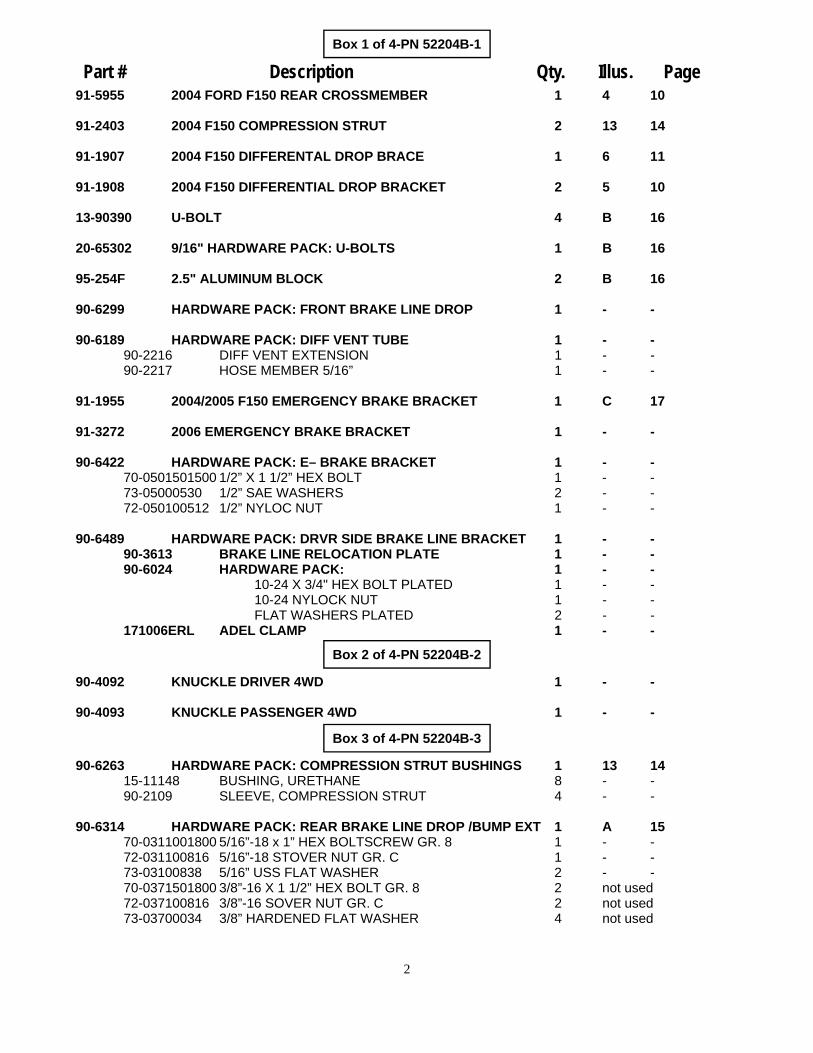
Part # Description Qty. Illus. Page
Box 1 of 4-PN 52204B-1
91-5955 2004 FORD F150 REAR CROSSMEMBER 1 4 10
91-2403 2004 F150 COMPRESSION STRUT 2 13 14
91-1907 2004 F150 DIFFERENTAL DROP BRACE 1 6 11
91-1908 2004 F150 DIFFERENTIAL DROP BRACKET 2 5 10
13-90390 U-BOLT 4 B 16
20-65302 9/16" HARDWARE PACK: U-BOLTS 1 B 16
95-254F 2.5" ALUMINUM BLOCK 2 B 16
90-6299 HARDWARE PACK: FRONT BRAKE LINE DROP 1 - -
90-6189 HARDWARE PACK: DIFF VENT TUBE 1 - - 90-2216 DIFF VENT EXTENSION 1 - - 90-2217 HOSE MEMBER 5/16” 1 - -
91-1955 2004/2005 F150 EMERGENCY BRAKE BRACKET 1 C 17
91-3272 2006 EMERGENCY BRAKE BRACKET 1 - -
90-6422 HARDWARE PACK: E– BRAKE BRACKET 1 - - 70-0501501500 1/2” X 1 1/2” HEX BOLT 1 - - 73-05000530 1/2” SAE WASHERS 2 - -
72-050100512 1/2” NYLOC NUT 1 - -
90-6489 HARDWARE PACK: DRVR SIDE BRAKE LINE BRACKET 1 - - 90-3613 BRAKE LINE RELOCATION PLATE 1 - - 90-6024 HARDWARE PACK: 1 - -
10-24 X 3/4" HEX BOLT PLATED 1 - - 10-24 NYLOCK NUT 1 - - FLAT WASHERS PLATED 2 - -
171006ERL ADEL CLAMP 1 - -
90-4092 KNUCKLE DRIVER 4WD 1 - -
90-4093 KNUCKLE PASSENGER 4WD 1 - -
90-6263 HARDWARE PACK: COMPRESSION STRUT BUSHINGS 1 13 14 15-11148 BUSHING, URETHANE 8 - - 90-2109 SLEEVE, COMPRESSION STRUT 4 - -
90-6314 HARDWARE PACK: REAR BRAKE LINE DROP /BUMP EXT 1 A 15 70-0311001800 5/16”-18 x 1” HEX BOLTSCREW GR. 8 1 - - 72-031100816 5/16”-18 STOVER NUT GR. C 1 - - 73-03100838 5/16” USS FLAT WASHER 2 - - 70-0371501800 3/8”-16 X 1 1/2” HEX BOLT GR. 8 2 not used 72-037100816 3/8”-16 SOVER NUT GR. C 2 not used
73-03700034 3/8” HARDENED FLAT WASHER 4 not used
Box 2 of 4-PN 52204B-2
Box 3 of 4-PN 52204B-3

3
Part # Description Qty. Illus. Page 90-6322 HARDWARE PACK: 1 - -
90-1915 2004 F150 COMPRESSION STRUT NUT PLATE 2 13 14 90-1966 DRILL TEMPLATE 1 4 10
90-6315 HARDWARE PACK: SWAY BAR DROP 1 - - 70-0431751800 7/16”-14 x 1 3/4" HEX BOLT GR. 8 4 12 13 72-043100816 7/16”-14 STOVER NUT GR. C 4 12 13 73-04300830 7/16” SAE FLAT WASHER 8 12 13
90-6316 HARDWARE PACK: DIFF DROP 1 - - 71-1210017510 12MM- 1.75 x 100MM HEX BOLT 10.9 3 5 10 M12D985 12MM- 1.75 STOVER NUT 10.9 3 5 10 73-01200830 12MM SAE FLAT WASHER 6 5 10
90-6751 HARDWARE PACK: 1 - - 90-5532 ECCENTRIC CAM BOLT 4 9 12 90-5533 ECCENTRIC CAM BOLT 4 9 12
90-6313 HARDWARE PACK: 2004 F150 CROSSMEMBER 1 9 12 .180CNUCZ 18MM STOVER 4 - - .180NWHDZ 18MM WASHERS 4 - -
90-6234 HARDWARE PACK: COMPRESSION STRUTS 1 - - 70-0501251800 1/2"-13 X 1 1/4" GR 8 HEX BOLT 2 13 14 70-0504001800 1/2"-13 X 4" GR 8 HEX BOLT 4 13 14
72-050100816 1/2"-13 GR 8 STOVER NUT 4 13 14 73-05000034 1/2" SAE HARDENED FLAT WASHER 10 13 14
90-6317 HARDWARE PACK: SPACER MOUNT 1 - - 72-043200810 7/16-20 GR. 8 PLATED HEX NUT 6 10a,11 13 73-04300830 7/16 SAE FLAT WASHER ZINC 6 10a,11 13
73-04300836 7/16 SPLIT LOCK WASHER 6 10a,11 13
90-6319 HARDWARE PACK: ZIP TIES 1 - - 10999 ZIP TIE, 11", BLACK 12 - -
91-1912 2004 F150 SWAY BAR DROP 2 12 13
90-6255 HARDWARE PACK: STEERING RACK DROP 1 - - 70-0625501800 5/8” X 5 1/2” GR 8 HEX BOLT 2 2a,2b,2c 8,9 72-062100816 5/8” USS GR 8 STOVER NUT 4 2a,2b,2c 8,9 73-06200034 5/8” SAE GR 8 FLAT WASHER 8 2a,2b,2c 8,9
90-6323 HARDWARE PACK: 1 - - 73-07500834 3/4" HARDENED FLAT WASHER 1 C 17
90-1083 REAR BRAKE LINE DROP 1 A 15
90-55089-3 FRONT BRAKE LINE EXTENSION (PASS) 1 - -
90-55089-4 FRONT BRAKE LINE EXTENSION (DRIVER) 1 - -
90-1964 STEERING RACK RELOCATION BRACKET 2 2a,2b,2c 8,9
91-1104 COMPRESSION STRUT MOUNT 2 13 14
91-5953 2004 F150 FRONT CROSSMEMBER 1 8 12

4
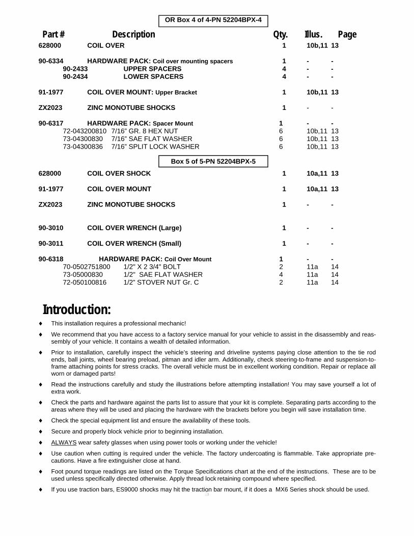
OR Box 4 of 4-PN 52204BMX-4
628000 COIL OVER SHOCK 1 10a,11 13
90-6334 HARDWARE PACK: Coil over mounting spacers 1 - - 90-2433 UPPER SPACERS 4 - - 90-2434 LOWER SPACERS 4 - -
91-1977 COIL OVER MOUNT 1 10a,11 13
MX6009 MX6 SERIES SHOCK (REAR) 1 - -
90-6317 HARDWARE PACK: Spacer Mount 1 - -72-043200810 7/16” GR. 8 HEX NUT 6 10b,11 13 73-04300830 7/16” SAE FLAT WASHER 6 10b,11 13 73-04300836 7/16” SPLIT LOCK WASHER 6 10b,11 13
90-6393 HARDWARE PACK: BRAKE LINE DROP (2005 MODEL) 1 - - 90-3202 BRAKE LINE DROP - - -
90-6715 HARDWARE PACK: SPACER MOUNT 1 - - 90-2726 1/2” Steering Rack Spacer 4 2a,2b,2c 8,9 90-8009 1/4” Steering Rack Spacer 4 2a,2b,2c 8,9
929504 9000 SERIES SHOCK (REAR) 2 - - 60859 SLEEVES 4 - - 91-2416 COIL SPACER 2 10a,11 13
Box 4 of 4-PN 52204B-4
OR Box 4 of 4-PN 52204BPS-4
ZX2023 PRO RUNNER MONOTUBE REAR SHOCKS 2 - -
91-2416 COIL SPACER 2 10b 13
OR Box 4 of 4-PN 52204BP-4
Part # Description Qty. Illus. Page
628000 COIL OVER SHOCK 1 10a,11 13
91-1977 COIL OVER MOUNT 1 10a,11 13
MX6009 MX6 SERIES SHOCK (REAR) 1 - -
90-3010 COIL OVER WRENCH (Large) 1 - -
90-3011 COIL OVER WRENCH (Small) 1 - -
90-6318 HARDWARE PACK: Coil Over Mount 1 - - 70-0502751800 1/2" X 2 3/4" BOLT 2 11a 14 73-05000830 1/2" SAE FLAT WASHER 4 11a 14 72-050100816 1/2” STOVER NUT Gr. C 2 11a 14
Box 5 of 5-PN 52204BMX-5
52204BP-4 PRO RUNNER MONOTUBE SHOCK KIT BOX 1 - -
ZX2007 PRO RUNNER MONOTUBE FRONT SHOCKS 2 - -
5
This installation requires a professional mechanic!
We recommend that you have access to a factory service manual for your vehicle to assist in the disassembly and reas-sembly of your vehicle. It contains a wealth of detailed information.
Prior to installation, carefully inspect the vehicle’s steering and driveline systems paying close attention to the tie rod ends, ball joints, wheel bearing preload, pitman and idler arm. Additionally, check steering-to-frame and suspension-to-frame attaching points for stress cracks. The overall vehicle must be in excellent working condition. Repair or replace all worn or damaged parts!
Read the instructions carefully and study the illustrations before attempting installation! You may save yourself a lot of extra work.
Check the parts and hardware against the parts list to assure that your kit is complete. Separating parts according to the areas where they will be used and placing the hardware with the brackets before you begin will save installation time.
Check the special equipment list and ensure the availability of these tools.
Secure and properly block vehicle prior to beginning installation.
ALWAYS wear safety glasses when using power tools or working under the vehicle!
Use caution when cutting is required under the vehicle. The factory undercoating is flammable. Take appropriate pre-cautions. Have a fire extinguisher close at hand.
Foot pound torque readings are listed on the Torque Specifications chart at the end of the instructions. These are to be used unless specifically directed otherwise. Apply thread lock retaining compound where specified.
If you use traction bars, ES9000 shocks may hit the traction bar mount, if it does a MX6 Series shock should be used.
628000 COIL OVER 1 10b,11 13
90-6334 HARDWARE PACK: Coil over mounting spacers 1 - -90-2433 UPPER SPACERS 4 - -
90-2434 LOWER SPACERS 4 - -
91-1977 COIL OVER MOUNT: Upper Bracket 1 10b,11 13
ZX2023 ZINC MONOTUBE SHOCKS 1 - -
90-6317 HARDWARE PACK: Spacer Mount 1 - -72-043200810 7/16” GR. 8 HEX NUT 6 10b,11 13 73-04300830 7/16” SAE FLAT WASHER 6 10b,11 13 73-04300836 7/16” SPLIT LOCK WASHER 6 10b,11 13
OR Box 4 of 4-PN 52204BPX-4
Part # Description Qty. Illus. Page
Introduction:
628000 COIL OVER SHOCK 1 10a,11 13
91-1977 COIL OVER MOUNT 1 10a,11 13
ZX2023 ZINC MONOTUBE SHOCKS 1 - -
90-3010 COIL OVER WRENCH (Large) 1 - -
90-3011 COIL OVER WRENCH (Small) 1 - -
90-6318 HARDWARE PACK: Coil Over Mount 1 - - 70-0502751800 1/2" X 2 3/4" BOLT 2 11a 14 73-05000830 1/2" SAE FLAT WASHER 4 11a 14 72-050100816 1/2” STOVER NUT Gr. C 2 11a 14
Box 5 of 5-PN 52204BPX-5
6
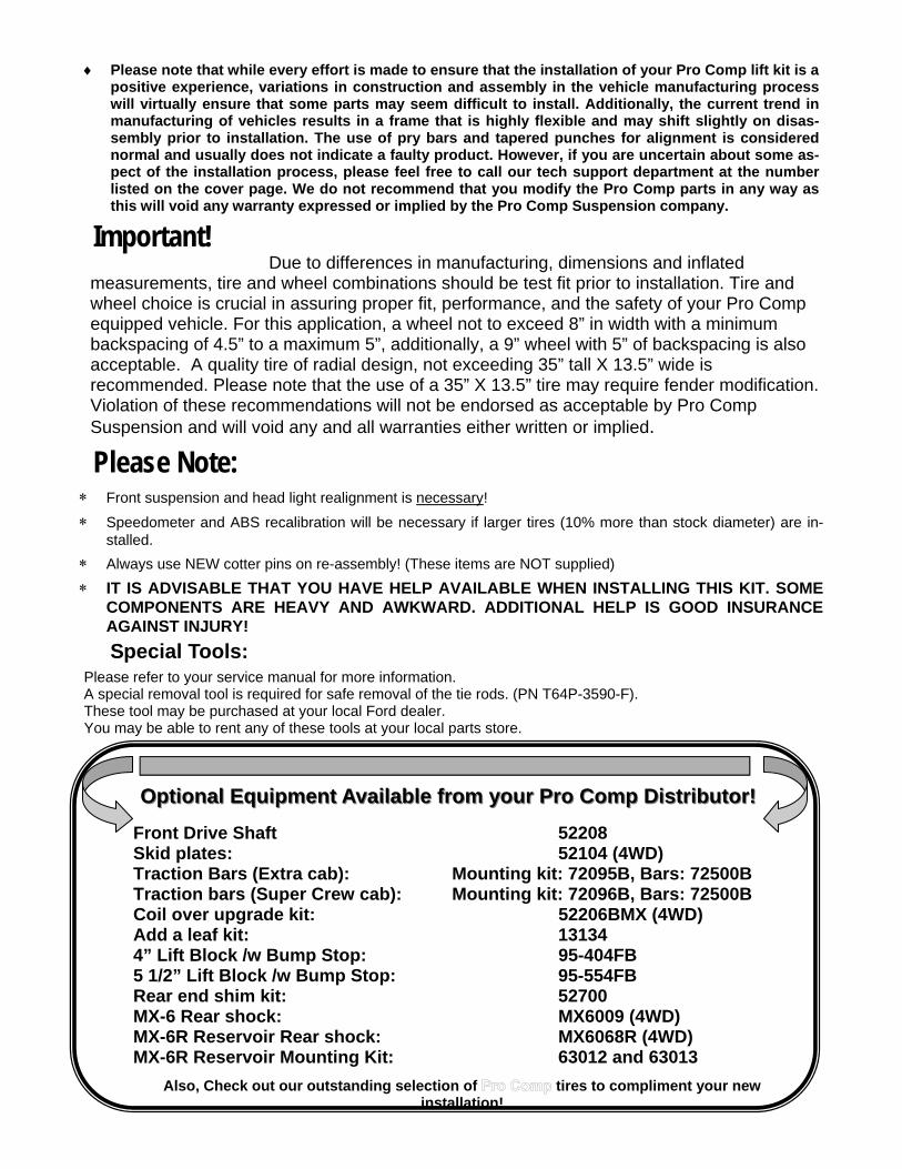
Please Note: Front suspension and head light realignment is necessary!
Speedometer and ABS recalibration will be necessary if larger tires (10% more than stock diameter) are in-stalled.
Always use NEW cotter pins on re-assembly! (These items are NOT supplied)
IT IS ADVISABLE THAT YOU HAVE HELP AVAILABLE WHEN INSTALLING THIS KIT. SOME COMPONENTS ARE HEAVY AND AWKWARD. ADDITIONAL HELP IS GOOD INSURANCE AGAINST INJURY!
Due to differences in manufacturing, dimensions and inflated measurements, tire and wheel combinations should be test fit prior to installation. Tire and wheel choice is crucial in assuring proper fit, performance, and the safety of your Pro Comp equipped vehicle. For this application, a wheel not to exceed 8” in width with a minimum backspacing of 4.5” to a maximum 5”, additionally, a 9” wheel with 5” of backspacing is also acceptable. A quality tire of radial design, not exceeding 35” tall X 13.5” wide is recommended. Please note that the use of a 35” X 13.5” tire may require fender modification. Violation of these recommendations will not be endorsed as acceptable by Pro Comp Suspension and will void any and all warranties either written or implied.
Special Tools:
Important!
Please refer to your service manual for more information. A special removal tool is required for safe removal of the tie rods. (PN T64P-3590-F). These tool may be purchased at your local Ford dealer. You may be able to rent any of these tools at your local parts store.
Front Drive Shaft 52208 Skid plates: 52104 (4WD) Traction Bars (Extra cab): Mounting kit: 72095B, Bars: 72500B Traction bars (Super Crew cab): Mounting kit: 72096B, Bars: 72500B Coil over upgrade kit: 52206BMX (4WD) Add a leaf kit: 13134 4” Lift Block /w Bump Stop: 95-404FB 5 1/2” Lift Block /w Bump Stop: 95-554FB Rear end shim kit: 52700 MX-6 Rear shock: MX6009 (4WD) MX-6R Reservoir Rear shock: MX6068R (4WD) MX-6R Reservoir Mounting Kit: 63012 and 63013
Also, Check out our outstanding selection of tires to compliment your new installation!
Optional Equipment Available from your Pro Comp Distributor!Optional Equipment Available from your Pro Comp Distributor!
Please note that while every effort is made to ensure that the installation of your Pro Comp lift kit is a positive experience, variations in construction and assembly in the vehicle manufacturing process will virtually ensure that some parts may seem difficult to install. Additionally, the current trend in manufacturing of vehicles results in a frame that is highly flexible and may shift slightly on disas-sembly prior to installation. The use of pry bars and tapered punches for alignment is considered normal and usually does not indicate a faulty product. However, if you are uncertain about some as-pect of the installation process, please feel free to call our tech support department at the number listed on the cover page. We do not recommend that you modify the Pro Comp parts in any way as this will void any warranty expressed or implied by the Pro Comp Suspension company.
7
1. Prior to installing this kit, with the vehi-cle on the ground. Measure the heightof your vehicle . This measurementcan be recorded from the center of thewheel, straight up to the top of the in-ner fender lip. Record the measure-ments below.
2. Ensure that your work space is ofadequate size and the work surface islevel. Place the vehicle in park and setparking brake. Place blocks both infront of and behind the rear wheels.Place your floor jack under the frontcross member and raise vehicle.Place jack stands under the framerails behind the front wheel wells andlower the frame onto the stands. Re-move the jack and remove the frontwheels.
3. Remove any skid plates if necessary.4. Work on one side of
the vehicle at a time.5. Remove the front
calipers from thefront disks by remov-ing the (2) retainingbolts. NOTE: Make sure you do not let the calipers hang on the brake lines or damage will occur.
6. Remove the front ro-tors from the fronthub.
7. Remove the dustcap and the nut fromthe end of the CV inthe hub and remove
the bolts from the inner CV flange. 8. Remove the anti-lock wiring and sen-
sor from the hub if applicable.9. Remove the vacuum line from the rear
of the hub.10.Remove the tie rod end nut and sepa-
rate from the knuckle . 11.Remove the upper ball joint nut from
the knuckle and separate using the appropriate tool.
12. Remove the lower ball joint nut, sepa-rate using the appropriate tool. Re-move the knuckle from the vehicle while pulling it away from the CV and set the knuckle aside.
13.Remove the nuts from the sway bar links on the lower a arm.
14.Mark the orientation and Remove the CV axles from the differential.
15. Remove the three nuts from the topof the coil over assembly and the one large nut and bolt on the bottom. Re-move the coil from the vehicle.
16. Remove the two bolts that retain the
Front Installation:
Illustration 1 View from rear
Rear cross member brace VIEW FROM REAR VIEW FROM FRONT
.75”
1.75”
LR: RR:
RF: LF:
8
lower a-arms and remove them from the truck.
17. Repeat on the other side of the vehi-cle.
18.Remove the sway bar and brackets. 19. Mark the drive shafts orientation.20.Disconnect the front drive shaft from
the differential and secure up and out of the way.
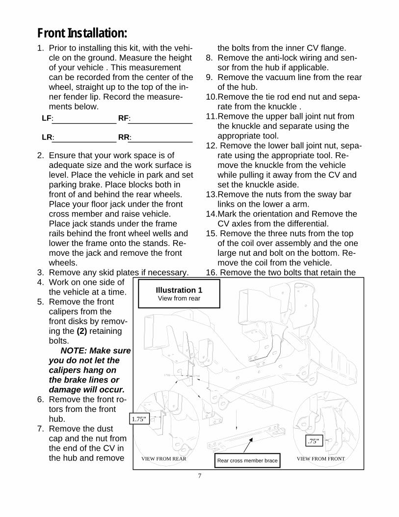
21. Remove the rear cross memberbrace; retain (2) of the bolts and nuts for reuse. See illustration 1.
22. Make sure that the front differential iswell supported, remove existing hard-ware from both passenger and driver side differential mounting areas. Carefully lower differential out of vehi-cle and set aside. Note the vent rout-ing for reinstall. Be careful the differ-ential is heavy.
23. Inspect the left (drivers), rear a-armpocket. On the rear hole measure 1.75” from the inside edge of the hole to the inside of the truck and mark a line. See illustration 1.
24.On the front hole measure .75” from the inside edge of the hole to the in-side of the truck and mark a line. Cut the left (drivers) rear a-arm pocket across these lines. See illustration 1.
25.Remove the steering rack mounting hardware and brackets. This hard-ware will be reused.
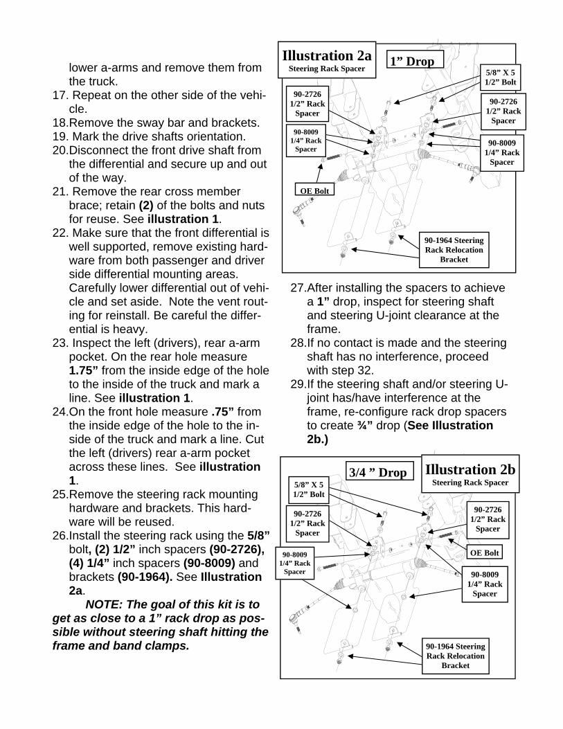
26.Install the steering rack using the 5/8” bolt, (2) 1/2” inch spacers (90-2726), (4) 1/4” inch spacers (90-8009) and brackets (90-1964). See Illustration 2a.
NOTE: The goal of this kit is to get as close to a 1” rack drop as pos-sible without steering shaft hitting the frame and band clamps.
27.After installing the spacers to achieve a 1” drop, inspect for steering shaft and steering U-joint clearance at the frame.
28.If no contact is made and the steering shaft has no interference, proceed with step 32.
29.If the steering shaft and/or steering U-joint has/have interference at the frame, re-configure rack drop spacers to create ¾” drop (See Illustration 2b.)
Illustration 2a Steering Rack Spacer
OE Bolt
90-1964 Steering Rack Relocation
Bracket
90-2726 1/2” Rack
Spacer
90-8009 1/4” Rack
Spacer
90-2726 1/2” Rack
Spacer
90-8009 1/4” Rack
Spacer
5/8” X 5 1/2” Bolt
1” Drop
Illustration 2b Steering Rack Spacer
90-1964 Steering Rack Relocation
Bracket
90-2726 1/2” Rack
Spacer
90-8009 1/4” Rack
Spacer
OE Bolt
3/4 ” Drop
90-2726 1/2” Rack
Spacer
90-8009 1/4” Rack
Spacer
5/8” X 5 1/2” Bolt

9
30.Inspect again for steering shaft and steering U-joint clearance at the frame. If no contact is made and the steering shaft has no interference, proceed with step 32.
31.If the steering shaft and/or steering U-joint still has/have interference at the frame, re-configure rack drop spacers to create ½” drop (See Illustration 2c.)
32.Check for steering shaft clearance to frame and band clamps, the dust boots and the clamps may have to be repositioned or removed. Torque the
5/8” steering rack hardware to 150 ft./lbs. and the OE bolts to manufactur-ers specifications.
33. Install the differential drop brackets91-1908 with the factory hardware into the frame, the jog will go towards the front of the truck. Leave loose. See illustration 3 & 4.
34. Install the rear cross member 91-5955 into the frame with the factory bolts. The heads will face the front of the truck. See illustration 5.
35. Place the drill template 90-1966 pro-vided over the left rear cross member bolt and into the slotted hole in the new cross member. Using the tem-plate drill the new 1/2” hole through the factory frame. See illustration 5.
36. Remove the drivers side rear crossmember bolt and swing the cross member away to the passenger side.
37. Hang the differential in the dropbrackets with the supplied hardware from pack 90-6316. The bolt heads should face towards the front of the vehicle. Leave the bolts loose. See illustration 3.
38. Using the differential drop extensionpack 90-6189 fit the new hose to the differential. Place the supplied plug in the end of the tube and connect the factory tube to it. Route the vent hose as previously noted. Use the supplied
Illustration 2c Steering Rack Spacer
90-1964 Steering Rack Relocation
Bracket
90-2726 1/2” Rack
Spacer
OE Bolt
90-8009 1/4” Rack
Spacer
5/8” X 5 1/2” Bolt
OE Bolt
1/2” Drop
12MM X 100MM
91-1908
OE BOLT
Illustration 3 View from rear
10
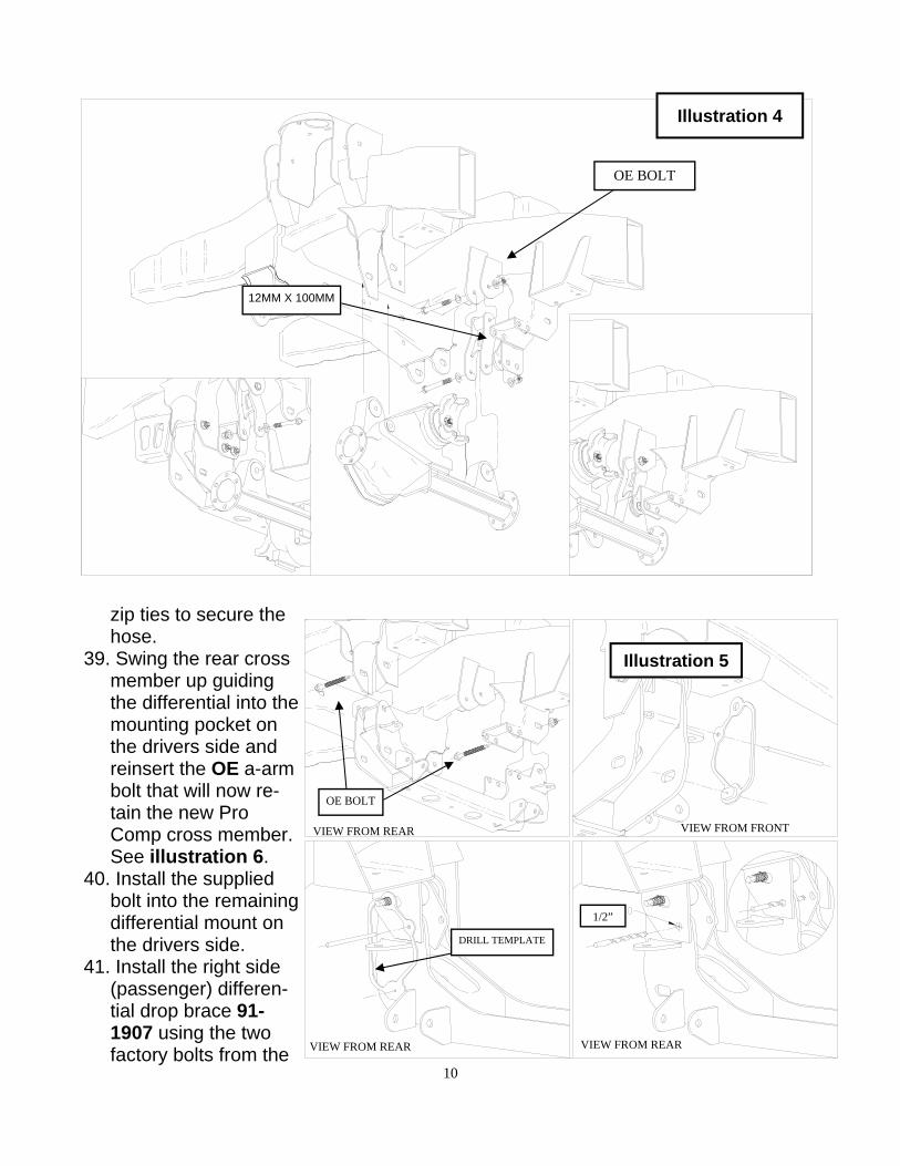
zip ties to secure the hose.
39. Swing the rear crossmember up guiding the differential into the mounting pocket on the drivers side and reinsert the OE a-arm bolt that will now re-tain the new Pro Comp cross member. See illustration 6.
40. Install the suppliedbolt into the remaining differential mount on the drivers side.
41. Install the right side(passenger) differen-tial drop brace 91-1907 using the two factory bolts from the
Illustration 4
12MM X 100MM
OE BOLT
Illustration 5
VIEW FROM FRONT VIEW FROM REAR
VIEW FROM REAR VIEW FROM REAR
1/2”
DRILL TEMPLATE
OE BOLT

11
rear cross member re-moved earlier and the one differential mount bolt. See illustration 7.
42. Install the front crossmember 91-5953 into origi-nal front A-arm mounting locations, using the factory bolts with the heads to the front, leave loose. Make sure the cam guides face the inside. See illustration 8.
43. Install the lower a-armsinto the new cross mem-bers with the supplied cam bolts 90-5533, cam eccen-trics 90-5532, 18mm washers and nuts. The cams should fit between the cam guides on the cross mem-bers. Center the cams in the guides. You will torque the bolts at the end of the install when the vehicle is on the ground. See illustration 9.
44. Torque the front and rear cross mem-ber mounting bolts to 135 ft./lbs.
45.Tighten all of the remaining hardware to factory specifications.
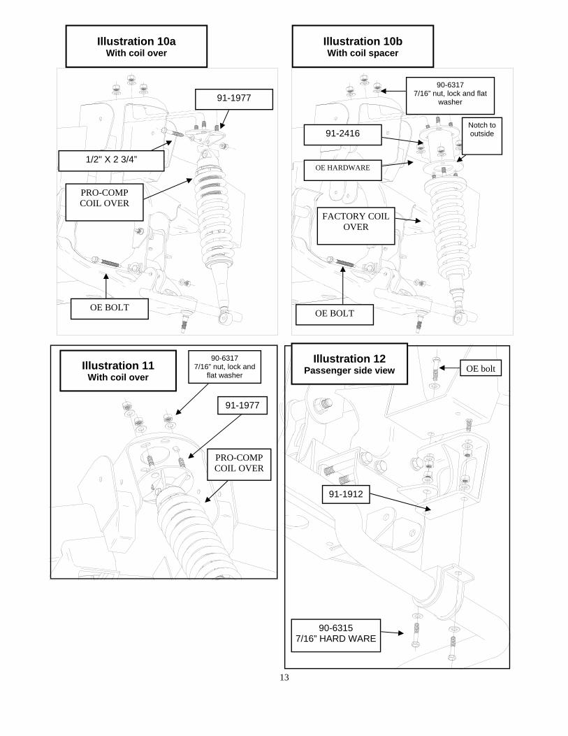
46. Install the front sway bar drop brack-ets 91-1912 to the frame using the factory sway bar mounting hardware. Leave loose. See illustration 12.
47. Insert the 7/16” bolts with the wash-ers from pack 90-6315 into the sway bar drops 91-1912. One bolt will pass through the tab from the rear cross member on bolt sides. See illustra-tion 12.
48.Attach factory sway bar and mounts to the new drop brackets.
49.Swing the sway bar ends up into posi-tion and loosely connect to the a-
Illustration 6 View from rear
91-5955
OE BOLT
Illustration 7 View from Drivers side
OE BOLT
91-5955
OE BOLT
12MM X 100MM
91-1907

12
arms, do not tighten until the truck is on the ground.
50. Torque the sway bar mount hardwareto 60 ft./lbs.
51. Transfer all the parts from the factoryknuckles to the supplied Pro-Comp knuckles. NOTE: Tighten all the factory hardware carefully. Be sure to fol-low the factory assembly proce-dures and torque specifications. The small aluminum vacuum cover bolts are Torqued to 11 ft/lbs.
52. WITH THE COIL OVERS. Insertmono ball spacers (90-2433) in the top of the coil over and mono ball spacers (90-2434) in the bottom of the coil over. NOTE: The spacers are a tight fit. A press might be needed to fit the spacers into the mono balls.
53.Install the new Pro-Comp coil over shock to the upper bracket 91-1977 with the supplied 1/2” X 2 3/4” hard-ware from pack 90-6318. Fasten up-per bracket to truck using the supplied 7/16” hardware on the top. See illus-
tration 10a and 11. 54.WITH THE COIL SPACERS. Attach
the spacer to the top of the shock us-ing the factory hardware. With the notch in the bottom ring facing the outside of the truck. Fit the shock and spacer into the stock mounting loca-tions. Fasten using the supplied hard-ware on the top. See illustration 10b.
55. Install the OE bolt through the lowershock mount and a-arm. Torque to factory specifications.
56. ON THE DRIVER’S SIDE ONLY, lo-cate and remove the inner most nut that secures the strut spacer to the frame and install the brake line reloca-tion plate 90-3613 from pack 90-6489. See enclosed instructions for details.
57.Support lower A-arms. Position new front knuckles. Attach knuckle to lower ball joint. Torque to 111 ft/lbs.
58. Attach the CV axles to the differentialand use thread locking compound and torque to factory specifications.
59.Then slide the CV through the knuckle. Attach the nut to the end of the CV shaft. Torque to 20 ft/lbs. and attach dust cap.
60. Attach the knuckle to the upper balljoint. Torque to 85 ft/lbs.
61. Turn tie rod 180 degrees and fasten
Illustration 8 Drivers side view
OE BOLT 91-5953
Illustration 9 Drivers side view
CAM ECCENTRIC 90-5532
CAM BOLT 90-5533
18MM HARDWARE
13
Illustration 12 Passenger side view
90-6315 7/16” HARD WARE
91-1912
OE bolt
Illustration 10a With coil over
90-6317 7/16” nut, lock and flat
washer
OE HARDWARE
FACTORY COIL OVER
OE BOLT
PRO-COMP COIL OVER
OE BOLT
91-1977
91-2416 Notch to outside
Illustration 10b With coil spacer
1/2" X 2 3/4”
Illustration 11 With coil over
91-1977
90-6317 7/16” nut, lock and
flat washer
PRO-COMP COIL OVER
14
tie rod end to the knuckle. Torque to 111 ft/lbs.
62.Connect the anti-lock wiring harness and sensor to the hub if applicable.
63. Attach the vacuum lines to the rear ofthe hub.
64. Repeat the installation on the otherside of the vehicle.
65.Install the front rotors on to the front hub.
66. Install the front calipers on to the frontrotors by reinstalling the retaining bolts. Torque to factory specifications.
67. Remove stock brake line bracketfrom frame. Carefully remount the bracket with the supplied brake line drops 90-55089-3 (PASS) and 90-55089-4(DVR) in between bracket and frame. Use factory hardware to fasten the shorter end of the bracket to the frame. Position the drops, best for your application. Use the supplied hardware from pack 90-6299 to fasten
OE bracket to the new brake line drop.
NOTE: 2005 models produced after 11/04 may require the use of longer brake line drops 90-3202 from hardware pack 90-6393. Care-fully unbolt and bend the factory metal brake lines to allow them to be bolted to the bottom of the brake line drops 90-3202.
WARNING: Make sure the brake lines that you just modified are still in the Ford factory plastic retainers attached to the inside of the frame and that they are not resting against any moving parts.
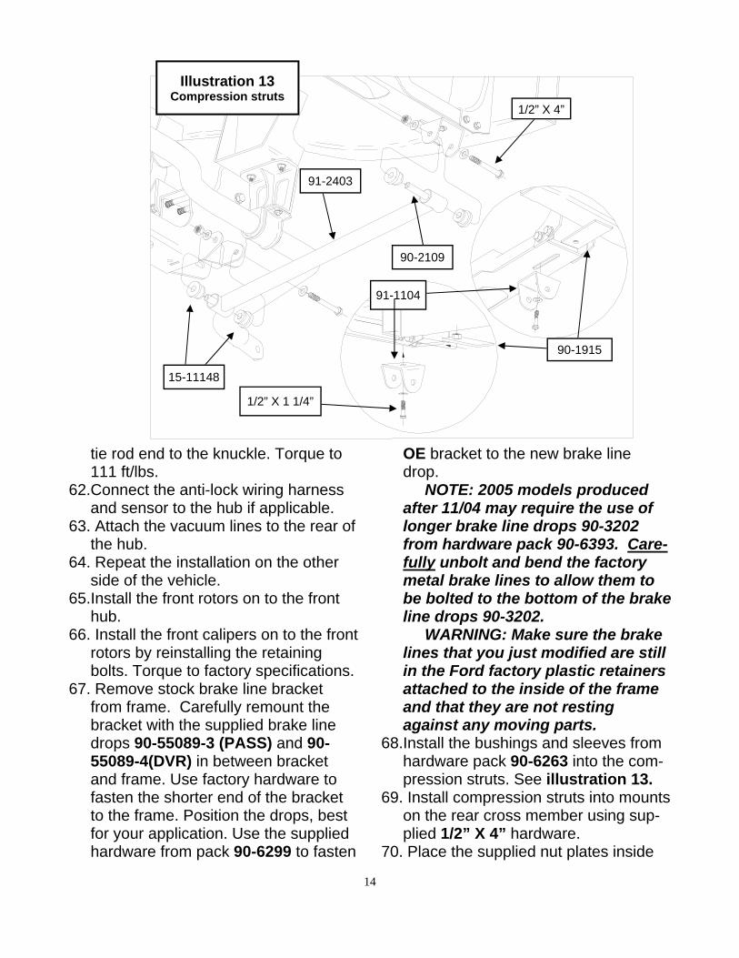
68.Install the bushings and sleeves from hardware pack 90-6263 into the com-pression struts. See illustration 13.
69. Install compression struts into mountson the rear cross member using sup-plied 1/2” X 4” hardware.
70. Place the supplied nut plates inside
Illustration 13 Compression struts
1/2” X 1 1/4”
1/2” X 4”
91-2403
90-2109
91-1104
90-1915
15-11148
15
1. Block the front tires and raise therear of the vehicle. Support the frame with jack stands forward of the rear springs.
2. Remove the rear wheels.
3. Remove the shocks on both sides ofthe vehicle. It may be necessary that you slightly raise the axle to unload the shocks for removal.
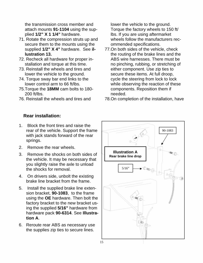
4. On drivers side, unbolt the existingbrake line bracket from the frame.
5. Install the supplied brake line exten-sion bracket, 90-1083, to the frame using the OE hardware. Then bolt the factory bracket to the new bracket us-ing the supplied 5/16” hardware from hardware pack 90-6314. See Illustra-tion A.
6. Reroute rear ABS as necessary usethe supplies zip ties to secure lines.
Rear installation:
Illustration A Rear brake line drop
90-1083
5/16”
the transmission cross member and attach mounts 91-1104 using the sup-plied 1/2” X 1 1/4” hardware.
71. Rotate the compression struts up andsecure them to the mounts using the supplied 1/2” X 4” hardware. See il-lustration 13.
72. Recheck all hardware for proper in-stallation and torque at this time.
73. Reinstall the wheels and tires andlower the vehicle to the ground.
74. Torque sway bar end links to thelower control arm to 66 ft/lbs.
75.Torque the 18MM cam bolts to 180-200 ft/lbs.
76. Reinstall the wheels and tires and
lower the vehicle to the ground. Torque the factory wheels to 150 ft/lbs. If you are using aftermarket wheels follow the manufacturers rec-ommended specifications.
77.On both sides of the vehicle, check the routing of the brake lines and the ABS wire harnesses. There must be no pinching, rubbing, or stretching of either component. Use zip ties to secure these items. At full droop, cycle the steering from lock to lock while observing the reaction of these components. Reposition them if needed.
78.On completion of the installation, have
16
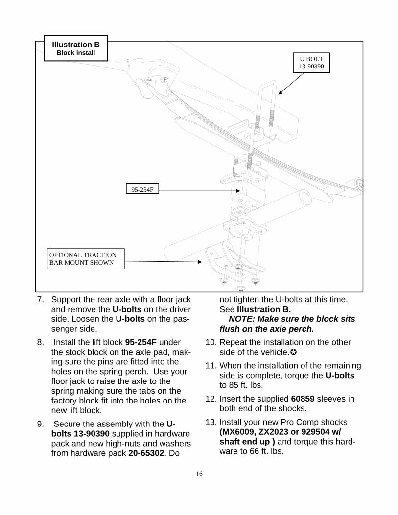
7. Support the rear axle with a floor jackand remove the U-bolts on the driverside. Loosen the U-bolts on the pas-senger side.
8. Install the lift block 95-254F underthe stock block on the axle pad, mak-ing sure the pins are fitted into the holes on the spring perch. Use your floor jack to raise the axle to the spring making sure the tabs on the factory block fit into the holes on the new lift block.
9. Secure the assembly with the U-bolts 13-90390 supplied in hardware pack and new high-nuts and washers from hardware pack 20-65302. Do
not tighten the U-bolts at this time. See Illustration B. NOTE: Make sure the block sits flush on the axle perch.
10. Repeat the installation on the otherside of the vehicle.
11. When the installation of the remainingside is complete, torque the U-boltsto 85 ft. lbs.
12. Insert the supplied 60859 sleeves inboth end of the shocks.
13. Install your new Pro Comp shocks(MX6009, ZX2023 or 929504 w/shaft end up ) and torque this hard-ware to 66 ft. lbs.
OPTIONAL TRACTION BAR MOUNT SHOWN
Illustration B Block install
95-254F
U BOLT 13-90390
17
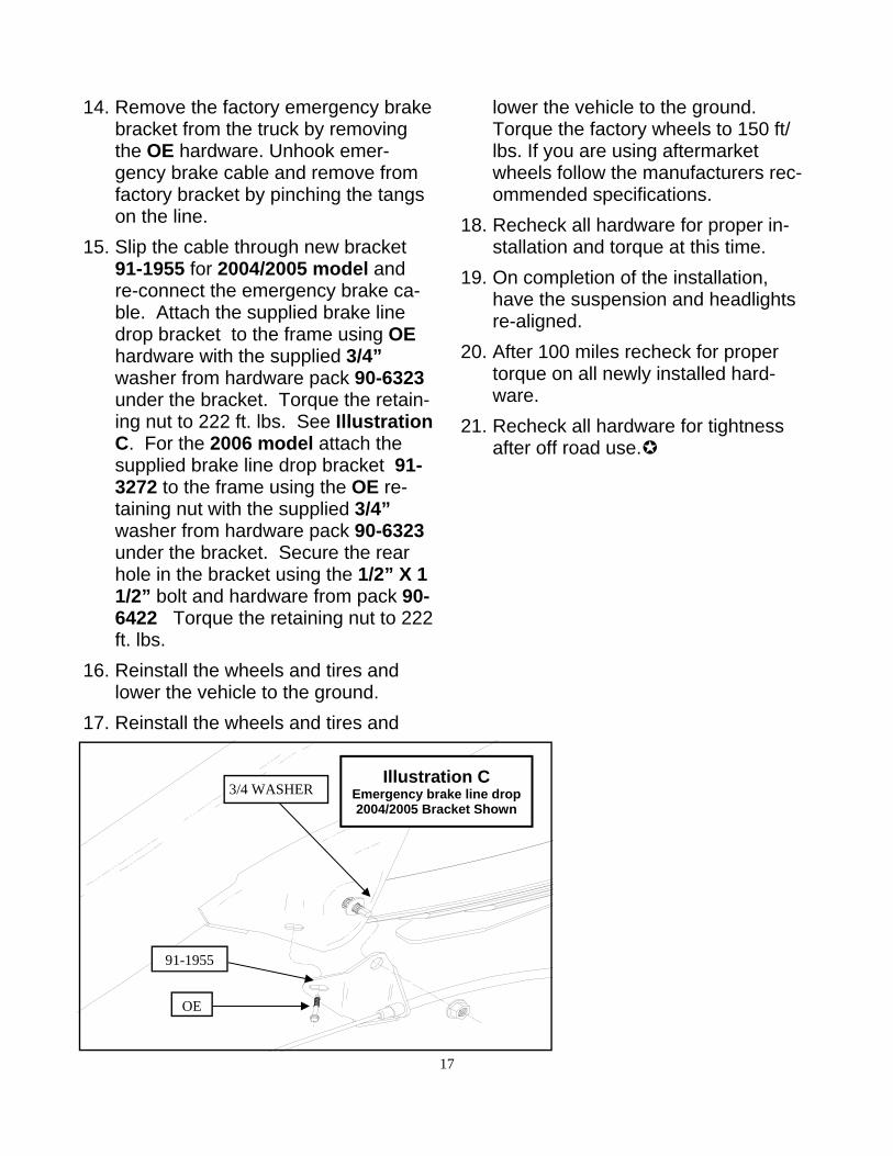
14. Remove the factory emergency brakebracket from the truck by removingthe OE hardware. Unhook emer-gency brake cable and remove fromfactory bracket by pinching the tangson the line.
15. Slip the cable through new bracket91-1955 for 2004/2005 model andre-connect the emergency brake ca-ble. Attach the supplied brake linedrop bracket to the frame using OEhardware with the supplied 3/4”washer from hardware pack 90-6323under the bracket. Torque the retain-ing nut to 222 ft. lbs. See IllustrationC. For the 2006 model attach thesupplied brake line drop bracket 91-3272 to the frame using the OE re-taining nut with the supplied 3/4”washer from hardware pack 90-6323under the bracket. Secure the rearhole in the bracket using the 1/2” X 11/2” bolt and hardware from pack 90-6422 Torque the retaining nut to 222ft. lbs.
16. Reinstall the wheels and tires andlower the vehicle to the ground.
17. Reinstall the wheels and tires and
lower the vehicle to the ground. Torque the factory wheels to 150 ft/lbs. If you are using aftermarket wheels follow the manufacturers rec-ommended specifications.
18. Recheck all hardware for proper in-stallation and torque at this time.
19. On completion of the installation,have the suspension and headlightsre-aligned.
20. After 100 miles recheck for propertorque on all newly installed hard-ware.
21. Recheck all hardware for tightnessafter off road use.
Illustration C Emergency brake line drop 2004/2005 Bracket Shown
OE
3/4 WASHER
91-1955

18
7.27.13: Updated quantity in Hardware pack 90-6489 in BOM. 11.13.14: Updated 90 PN’s to 91’s. Added BP,BPS, and BPX information to the BOM and text. Updated style and format of BOM. Added step 52 mono ball installation into coil over.
Revision Page:

The PRO COMP PROMISE WARRANTY At Pro Comp, we know you have many choices when selecting products to personalize your vehicle. You should demand nothing but the highest quality available and have total confidence that the products you selected are the best in the industry. It is for these reasons that Pro Comp Suspension products are backed by the best warranty in the industry...the Pro Comp Promise! Pro Comp promises that its products will last a lifetime or we will replace it free of charge. It’s that simple! Because of our commitment to quality and manufacturing excellence, we are able to stand behind our products. FOREVER. It is Pro Comp’s Promise that if one of our suspension products breaks not due to misuse, neglect or vandalism, we will re-place it. Whether you are the original purchaser or not, you can be assured that we will make it right. The Pro Comp Promise covers all suspension products including shocks and steering stabilizers. Buy Pro Comp Suspension today and enjoy it for the rest of your life! That’s our Pro Comp Promise! Notice to Owner, Operator, Dealer and Installer: Vehicles that have been enhanced for off-road performance often have unique handling characteristics due to the higher center of gravity and larger tires. This vehicle may handle, react and stop differently than many passenger cars or unmodi-fied vehicles, both on and off–road. You must drive your vehicle safely! Extreme care should always be taken to prevent ve-hicle rollover or loss of control, which can result in serious injury or even death. Always avoid sudden sharp turns or abrupt maneuvers and allow more time and distance for braking! Pro Comp reminds you to fasten your seat belts at all times and reduce speed! We will gladly answer any questions concerning the design, function, maintenance and correct use of our products. Please make sure that the Dealer / Installer explains and delivers all warning notices, warranty forms and instruction sheets included with Pro Comp product. Warranty and Return Policy: Pro Comp warranties its full line of products to be free from defects in workmanship and materials for the life of the product. Pro Comp’s obligation under this warranty is limited to repair or replacement, at Pro Comp’s option, of the defective product. Any and all costs of removal, installation, freight or incidental or consequential damages are expressly excluded from this warranty. Pro Comp is not responsible for damages and / or warranty of other vehicle parts related or non-related to the in-stallation of Pro Comp product. A consumer who makes the decision to modify his vehicle with aftermarket components of any kind will assume all risk and responsibility for potential damages incurred as a result of their chosen modifications. War-ranty coverage does not include consumer opinions regarding ride comfort, fitment and design. Warranty claims can be made directly with Pro Comp or at any factory authorized Pro Comp dealer. IMPORTANT! To validate the warranty on this purchase please be sure to mail in the warranty card. Claims not covered under warranty * Parts subject to normal wear; this includes bushings, bump stops, ball joints, tie rod ends and heim joints.* Finish after 90 days.* Damage caused as a result of not following recommendations or requirements called out in the installation manuals.Pro Comp MX Series coil-over shocks are considered a serviceable shock with a one-year warranty against leakage only. Rebuild service and replacement parts will be available and sold separately by Pro Comp. Contact Pro Comp for specific service charges. Pro Comp accepts no responsibility for any altered product, improper installation, lack of or improper main-tenance or improper use of our products.