Embed Size (px)
Citation preview
I J C T A, 7(2) December 2014, pp. 191-199© International Science Press
* Assistant Professor Department of EEE, Jansons Institute of Technology, Coimbatore, Tamilnadu, India** PG Scholars Department of EEE, VSB Engineering College, Karur, Tamilnadu, India
Power Management Scheme forPhotovoltaic/Battery Hybrid System inMicrogrid*Sathish Kumar Shanmugam, **Dhivya Bharathi Sundaramurthy,**Ayswarya Swami Nathan and **Sathya Priya Natrayan
ABSTRACT
In this paper a novel strategy of power management for hybrid systems in microgrids is proposed. To improve theeffectiveness of the system control strategies such as adaptive droop control technique and voltage source controlhas been employed in the PV/battery unit to operate as voltage source. Internal power flow management andadaptive droop control is done to maintain the grid voltage and frequency that are considered to be the main featureof power management that is employed in this paper. This scheme is proposed to share the load with other sourceswhile charging the battery. This in turn increases the efficiency of the overall system that is used to satisfy the needsof the microgrids. The employed PV/battery unit can not only track the maximum power like MPPT (MaximumPower Point Tracking) but also supply the maximum PV power to the microgrids as long as there is sufficient loadthat is to be supplied with the power generated by the hybrid system. The control strategy employed is also designedto modify the operating point of PV to autonomously whenever the available PV power is higher than the load andthe battery is completely charged. Moreover, the battery can operates as separate storage unit that can regulatevoltage and frequency and supply deficit power to the micro grid. The various strategies employed are the PI andMPPT (Maximum Power Point Tracking) along with Phase Locked Loop (PLL) is employed in the management ofpower in a hybrid system. The applied adaptive droop control does not depend on the communications and anystate machines. The system performance is studied by using MATLAB software and the output is analysed.
Index Terms: Micro grid, droop control, PV, battery storage, Power management strategy.
I. INTRODUCTION
A large number of interconnected solar panels are used in PV array. These panels may be installed asstationary or with sun tracking mechanism. It is an important factor that the solar PV output and the loadmatching is done in an increased manner, hence Maximum Power Point Tracker (MPPT) is employed. ThePV arrays which is given a most attractive option among the renewable energy resources.
It is employed in vast applications due to its high efficiency, increased reliability and low maintenance.Due to its advantages it is being widely employed in various applications through roof top supply source.The main advantage is that it can be located at the place of use and no distribution network is needed.Various applications of solar PV system are,
• Grid Interactive PV Power Generation
• Water Pumping
• Lighting
• Medical Refrigeration

192 Sathish Kumar Shanmugam, Dhivya Bharathi Sundaramurthy and et al.
• Village Power
• Telecommunication And Signaling
• Solar Furnaces
One of the main drawbacks of the PV system is the reduction of energy generation which is due to themismatching conditions and partial shading. To overcome the above drawback management techniqueshave been introduced to reduce the above problems. The grid connected PV system can be more efficientand reliable with an additional energy storage battery system.
In a grid connected system the battery storage is crucial in the operation of microgrids, which is usedfor the regulation of frequency and voltage when there is no alternate generation. It is also necessary toensure that the load is supplied with sufficient power even in the absence of intermediate power. In such acase an energy storage unit is employed that is connected to microgrids through voltage source controller.
To avoid this problem power management strategy has been employed between PV and battery units.Normally the battery and the other sources connected to the grid is controlled by certain droop controlstrategies when there is an occurrence of insufficient from the PV to the micro grid. This droop controlstrategy is used to prevent the battery from depletion. The depletion of battery may cause damage in theloads connected to microgrids. The main purpose of battery is not only for the storage purpose but also usedto supply or absorb power during fault conditions.In this scheme PV and battery units along with EMS(Energy Management System) which is used to measure the SOC (State Of Charge) of the battery is employed.To overcome this problem a hybrid system along with the PV and battery is employed which is called theDG hybrid unit. This hybrid unit cannot be connected directly to the grid, it requires certain droopcontrol schemes. This control scheme is used to coordinate the features of the grid connected system withthe micro grid system. This paper principally involves two basic power management strategies as shownbelow
• Internal Power Flow Management
• Voltage Control Scheme
Internal Power Flow Management manages the flow of power among the battery, PV array, DC link sothat power balance is maintained among the hybrid system.
Voltage Control Scheme is responsible for the flow of power between the battery and the PV arraywhich maintains the balance of power in the hybrid system.
II. SYSTEM DESCRIPTION
The proposed scheme is the system that combines the following features,
• The load is effectively shared between the hybrid unit and other available sources.
• The hybrid unit is capable of supplying the maximum power to the microgrids as long as there issufficient load.
• The proposed condition has the efficiency to follow the load demand whenever the PV available isgreater and the battery is charged completely.
• Efficient frequency regulation and voltage regulation is provided such that the deficient power inmicrogrids is supplied.
The method employs an adaptive multi-segment droop control method and a multi-loop control strategywithout relying on the basic methods such as communications and machines to switch among the variousoperating modes that prevail in the system during operating condition.
Power Management Scheme for Photovoltaic/Battery Hybrid System in Microgrid 193
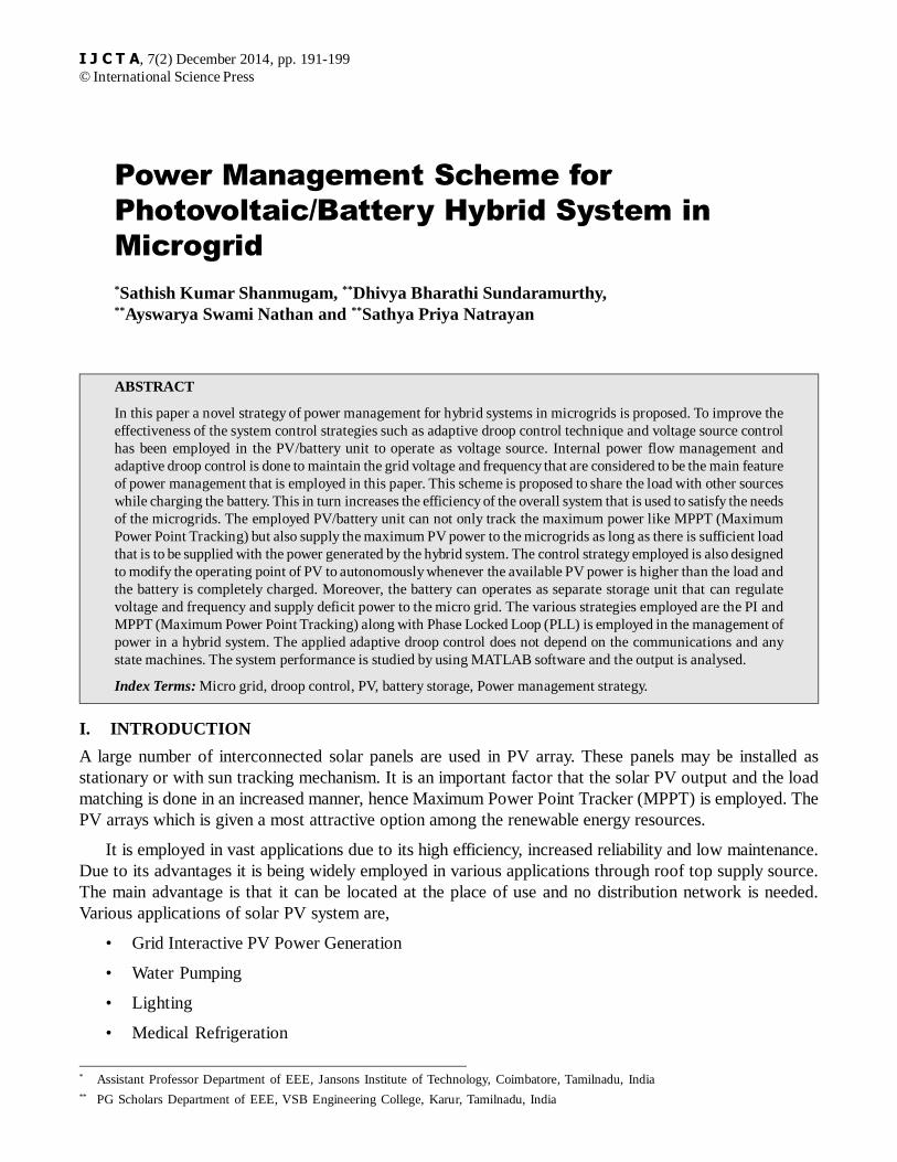
II. INTERNAL POWER FLOW MANAGEMENT
The internal power flow management is managed by using two main components such as MPPT (MaximumPower Point Tracking) and PID controller.
MPPT is an electronic DC-DC converter. It is a device where the grid connected inverters, battery andother devices so that it gets the maximum power from the photovoltaic devices. The MPPT samples theoutput of the cells and gives proper resistance during the solar irradiation and temperature in the solar cellsfor any given environmental conditions. MPPT are usually integrated with electric power converters sothat it provides current conversion, voltage conversion, filtering purposes etc,
(a) Solar inverters convert AC-DC and incorporate MPPT and apply proper resistance so that the systemobtains maximum power.
(b) MPP (Maximum Power Point)is the product of VMPP
(MPP voltage) and IMPP
(MPP current).MPPT isclassified into various types based on its applications such as
• Perturb and Observe
• Incremental Conductance
• Current Sweep Method
• Constant Voltage
In a grid connected PV system the MPPT will always try to operate the PV panel at its maximum power.The MPPT controllers follow one of the above mentioned algorithm and switches between the operatingconditions in the system.
Proportional– integral- derivative controller (PID Controller) is a loop control feedback mechanism,which is used to calculate the error values between the measured and desired values. There are three terms
Figure 1: Schematic Diagram of PV/battery Hybrid System.
194 Sathish Kumar Shanmugam, Dhivya Bharathi Sundaramurthy and et al.
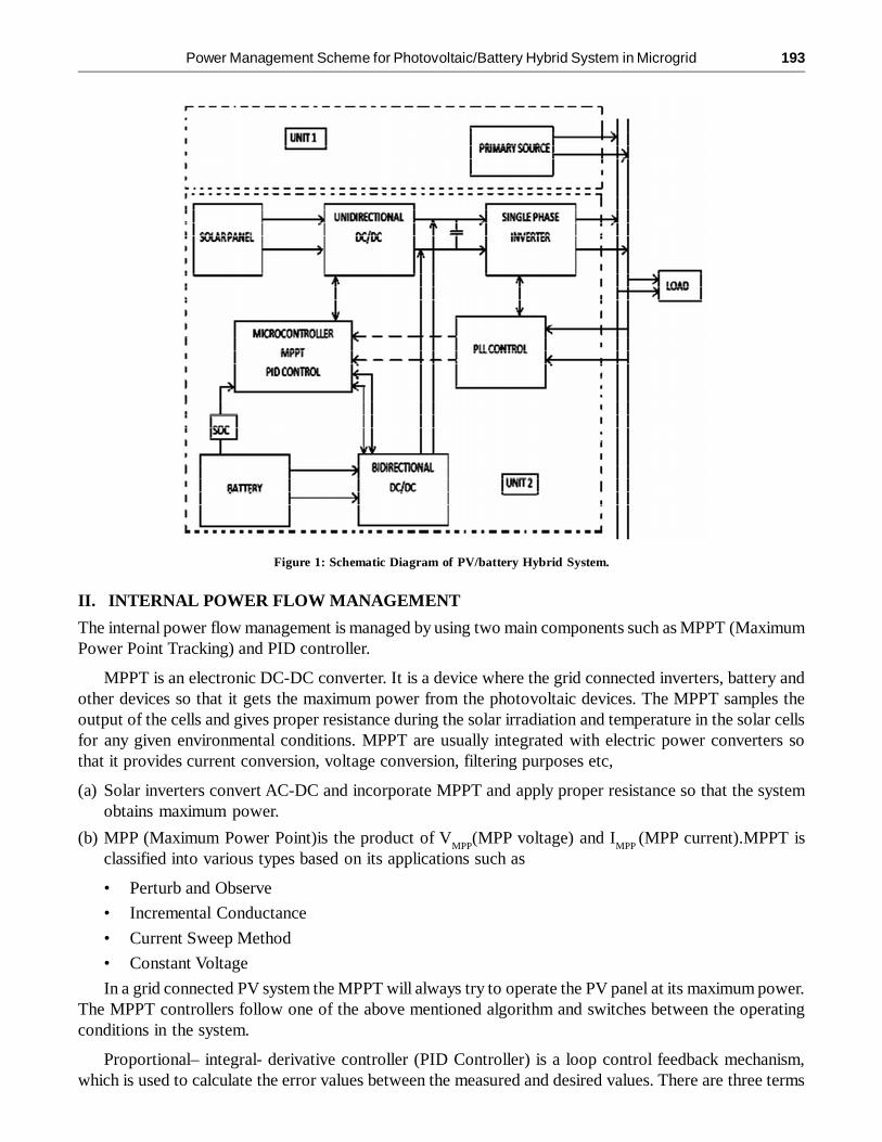
present in PID controller they are proportional term, integral term and a derivative term. The output fromthe above they are summed together. The block diagram of PID controller is shown below,
Figure 2: Schematic Diagram of PID Controller
The PID controller transfer function is given by,
PID(s) = Kp + K
i/s+ sK
d (1)
Thus by using a PID controller the overall performance is improved when compared with using asimple proportional or integral controller alone. PID controller operates on the error in the feedback system.
The power flow in the internal power flow management is categorized into two parts the MPPT andSOC (State of Charge). During the MPPT part the V
PV-REF is generated by the MPPT algorithm, this assumes
that the charge of the battery present in the system is always less than that of the maximum charge of thebattery. When the SOC of the battery increases beyond the maximum value the PID control loop controlsthe PV power so that it is away from the maximum power point (MPP), thereby reducing the power extractedfrom the PV array, until the battery current drops to zero. At this point the SOC of the battery is maximum,in such a case the PID output disables the MPPT algorithm and forces it to stay at current V
MPPT, else it
keeps searching for the maximum power from the PV. This is called the SOC strategy.
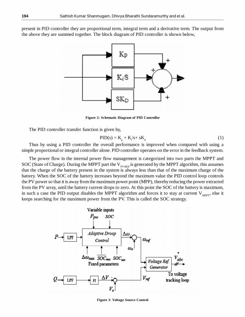
Figure 3: Voltage Source Control

Power Management Scheme for Photovoltaic/Battery Hybrid System in Microgrid 195
III. VOLTAGE SOURCE CONTROL
In VSC the system is controlled as voltage source. Here the frequency and the reference voltage trackingare done. The reference frequency is generated with the help of the real power in the system by the adaptivedroop control system. The LPF (Low Pass Filter) block present in the below diagram is a first order lowpass filter. The main purpose of this LPF is to remove the harmonics in the output. The control strategydepends on the SOC of the battery.
When the SOC of the battery is below the minimum limit then the control strategy the first priority isgiven to the charge of the battery and next to the power sharing. On the other hand, when the SOC of thebattery is between the minimum and maximum of the charge of the battery.
Else the micro grid is shared with the hybrid unit and the excess PV power is stored in the battery. If theSOC exceeds the maximum value the hybrid system will supply the power to the microgrid as long as thereis sufficient load otherwise it will store the excess in the battery. There are certain cases where conditionsfrom different criteria as mentioned above takes place. In such a case the internal power management loopcontrol is performed which reduces the ability of PV to extract Maximum Power Point Tracking (MPPT).By reducing the power output of the PV the system can effectively follow the load change that occurs in thesystem.
Figure 4: SOC Operating Scenario
Various operating scenario based on the SOC (State Of Charge) of the battery is described in Fig.(3).Spacevector pulse width modulation technique is employed in the closed loop control scheme as one of theeffective PWM(Pulse Width Modulation) technique.
Space Vector Pulse Width Modulation (SV-PWM) is actually just a modulation algorithm which translatesphase voltage (phase to neutral) references, coming from the controller, into modulation times/duty-cyclesto be applied to the PWM peripheral. It is a general technique for any three-phase load, although it has beendeveloped for motor control. SV-PWM maximizes DC bus voltage exploitation and uses the “nearest”

196 Sathish Kumar Shanmugam, Dhivya Bharathi Sundaramurthy and et al.
vectors, which translates into a minimization of the harmonic content. The classical application of SV-PWM is vector motor control, which is based on the control of currents’ projection on two orthogonalcoordinates (direct and quadrature, dq), called Field Oriented Control (FOC). The basic concept is thatwith a known motor and known voltage output pulses you can accurately determine rotor slip by monitoringcurrent and phase shift. The controller can then modify the PWM “sine” wave shape, frequency or amplitudeto achieve the desired result.
IV. POWER MANAGING SCENARIO
The major advantage of the power management scenario is that it overcomes the problem of black-outs.The shedding of load during the lack of power secures the equipments, by switching of the renewablesources. It reduces the electricity cost during the peak hours. During the low load periods the systemautomatically sheds away the low priority sources in the hybrid system. The power management shares theavailable active and reactive power that is available in the system. This power sharing scenario reduces thecable necessity to connect various sources to the load.
V. SIMULATION AND RESULT
The wind energy renewable source is employed along with the PV/Battery hybrid system in the proposedpaper. The management of power is effectively carried out among the wind, solar power and the battery asshown in fig.5. The output Measurement block gives the signal to the flow control block that consists ofideal switches that operates as per as the signal from the output measurement. Based on the switchingperformance the sources act to follow the change in load conditions.
Figure 5: Simulation Diagram
Based on the load value the sources are given priorities according to the switching signals from theflow control block. During the off load period the battery that has been charged continues to deliver thepower to the load. During the peak hours the renewable sources continues to deliver the power to the load.
The closed loop control with the help of the feedback obtained from the load settings converts the abcframe of the output to the dq reference frame such that the difference of the reference and the measuredvalue can be calculated. This block performs the abc to dq0 transformation on a set of three-phase signals.

Power Management Scheme for Photovoltaic/Battery Hybrid System in Microgrid 197
In the closed loop control the abc to dq0 transformation is done on a set of three phase signals as givenbelow :
Vd = 2/3*[Va*sin(wt) + Vb*sin(wt-2pi/3)+ Vc*sin(wt+2pi/3)] (2)
Vq = 2/3*[Va*cos(wt) + Vb*cos(wt-2pi/3)+ Vc*cos(wt+2pi/3)] (3)
V0 = 1/3*[Va + Vb + Vc ] (4)
It computes the direct axis Vd, quadratic axis Vq, and zero sequence V0 quantities in a two axis rotatingreference frame. This transformation is commonly used in three-phase electric machine models where it isknown as the Park transformation.
For the dq0 to abc transformation the block transforms three quantities (direct axis, quadature axis andzero-sequence components) expressed in a two axis reference frame back to phase quantities. The followingtransformation is used,
Va = [Vd*sin(wt) + Vq*cos(wt) + Vo] (5)
Vb = [Vd*sin(wt-2pi/3) + Vq*cos(wt-2pi/3) + Vo) (6)
Vc = [Vd*sin(wt+2pi/3) + Vq*cos(wt+2pi/3) + Vo) (7)
where w = rotation speed (rad/s) of the rotating.Input1contains the vectorized signal of [Vd Vq V0]components. Input 2 must contain a [sin (wt) cos (wt)] two dimensional signal containing the three [Va VbVc] phase sinusoidal quantities.
Ualpha = 2/3*(Ua-0.5*Ub-0.5*Uc); (8)Ubeta=2/3*(sqrt(3)/2*Ub-sqrt(3)/2*Uc); (9)
li=(3/2); (10)
The unit delay block samples and hold with one sample period delay. The clark transformation is donewith the following clark function.The output measurement block consists of Phase Locked Loop (PLL).thissystem can be used to synchronize on a set of variable frequency, three-phase sinusoidal signals. If theAutomatic Gain Control is enabled, the input (phase error) of the PLL regulator is scaled according to theinput signals magnitude. The RMS block employed computes the true RMS value of input signal. TheRMS value is calculated over a running window of one cycle of the specified frequency. The numericalinputs that are given can be viewed from the display block. The simulated result during peak hour isgenerated and given in fig. 6.
Figure 6: Closed Loop Control Block

198 Sathish Kumar Shanmugam, Dhivya Bharathi Sundaramurthy and et al.
The simulated result shows the priority of the renewable sources according to the load requirements.When the load current reaches the peak value the graph shows that the hybrid system effectively functionsto follow the load change.
The major scope of the project is to employ effective power management in areas such as,
• Home appliances
• Portable power
• Power train
• Large industrial power generation
The major advantage of the power management scenario is that it overcomes the problem of black-outs. The shedding of load during the lack of power secures the equipments, by switching of the renewablesources. It reduces the electricity cost during the peak hours. During the low load periods the systemautomatically sheds away the low priority sources in the hybrid system. The power management shares theavailable active and reactive power that is available in the system. This power sharing scenario reduces thecable necessity to connect various sources to the load.
VI. CONCLUSION
In this paper a novel strategy for hybrid PV/battery in a utility grid has been proposed effectively. In thisproposed scheme the PV unit is operated as voltage source which employs two control strategies such as
Figure 6: Simulation Result

Power Management Scheme for Photovoltaic/Battery Hybrid System in Microgrid 199
internal power flow control and the voltage source control is employed. The control strategy employed isalso designed to modify the operating point of PV to autonomously whenever the available PV power ishigher than the load and the battery is completely charged. Moreover, the battery can operates as separatestorage unit that can regulate voltage and frequency and supply deficit power to the micro grid.
REFERENCES[1] N. Asano and T. Saga, “PV Technology trends and industry’s role,” in In Conf. Rec. IEEE International Electron Devices
Meeting, 2008, pp.1–6.
[2] F. Ongaro, S. Saggini, and P. Mattavelli, “Li-ion battery supercapacitor hybrid storage system for a longlifetome,photovoltaic-based wireless sensor network,” IEEE Trans. Power Electron., Vol. 27, No. 9, pp. 3944–3952, Sep.2012.
[3] H. Mahmood, D. Michaelson, and J. Jiang, “Control strategy for a standalone PV/battery hybrid system,” in Conf. Proc.IEEE Industrial Electronics Conference, 2012, pp. 3412–3418.
[4] S. J. Chiang, H.-J. Shieh, and M.-C. Chen, “Modeling and control of a PV charger system with SEPIC converter,” IEEETrans. Ind. Electron., Vol. 56, No. 11, pp. 4344–4353, Nov. 2009.
[5] H. Fakham, D. Lu, and B. Francois, “Power control design of a battery charger in a hybrid active PV generator for load-following applications,” IEEE Trans. Ind. Electron., Vol. 58, No. 1, pp. 85–94, Jan. 2011.
[6] B. I. Rani, G. S. Ilango, and C. Nagamani, “Control strategy for power flow management in a PV system supplying DCloads,” IEEE Trans. Ind. Electron., Vol. 60, No. 8, pp. 3185–3194, Aug. 2013.
[7] C. Wang and M. H. Nehrir, “Power management of a stand-alone wind/photovoltaic/fuel cell energy system,” IEEE Trans.Energy Con- vers., Vol. 23, No. 3, pp. 957–967, Sep. 2008.
[8] K. T. Tan, P. L. So, Y. C. Chu, and M. Z. Q. Chen, “Coordinated control and energy management of distributed generationinverters in a microgrid,” IEEE Trans. Power Del., Vol. 28, No. 2, pp. 704–713, Apr. 2013.
[9] K. Brabandere, B. Bolsens, J. V. Keybus, A. Woyte, J. Driesen, and R. Belmans, “A voltage and frequency droop controlmethod for parallel inverters,” IEEE Trans. Power Electron., Vol. 22, No. 4, pp. 1107–1115, Jul. 2007.
[10] R. H. Lasseter and P. Piagi, “Providing premium power through dis- tributed resources,” in In Conf. Rec. IEEE 33rdHICSS, 2000, pp. 1–9.
[11] S. Bae and A. Kwasinski, “Dynamic modeling and operation strategy for a microgrid with wind and photovoltaic resources,”IEEE Trans. Smart Grid, Vol. 3, No. 4, pp. 1867–1876, Dec. 2014.


![Forecasting Earth Quake Using Back Propagation Algorithm ...serialsjournals.com/serialjournalmanager/pdf/1483683448.pdf · successful implementation of predicting earthquakes. [1]](https://img.dokumen.tips/doc/110x75/5aaa47487f8b9a95188de25c/forecasting-earth-quake-using-back-propagation-algorithm-implementation-of-predicting.jpg)