Embed Size (px)
Citation preview
Voltage Disturbances Identification and Mitigation using SRF Controlled DVR in Distribution SystemS. Vijaya Laxmi* and P.V. Ramana Rao**
Abstract: Now-a-days the most noticeable topic for electrical engineer is power quality problems in power system. Those power quality problems occur due to voltage disturbances in system. The electrical system faults, switching of large loads or energization of transformers will lead to voltage disturbance. Such voltage disturbances cause short term rapid change in amplitude of voltage. This voltage changes such as temporary voltage rise (Swell) or voltage reduction (Sag) and are more frequent and have severe impact on power system. This paper investigates the identification and mitigation of voltage sag, swell and sag swell problems. The problems are mitigated by SRF (Synchronous Reference Frame Theory) based DVR (Dynamic Voltage Restorer). The performance of DVR based Synchronous reference frame theory (SRF) for the mitigation of voltage sag, swell, sag swell in different phase voltages is tested and Simulation results are carried out by MATLAB\SIMULINK to analyze the proposed method.
Keywords: Power quality, Voltage disturbances, Dynamic Voltage Restorer (DVR), Synchronous Reference Frame Theory (SRF), Balanced and Un Balanced Voltage.
INTRODUCTION1. Delivering power with good quality to the end consumers is very important as loads are sensitive to power quality disturbances. Load demand is unpredictable in nature and one of the key aspects to monitor in power system. As load varies, the line voltage varies and causes system voltage to be disturbed. Voltage disturbance is a type of power quality issue and needs to be addressed. A small change in voltage can disturb the load profile and affects the end user. High voltage above nominal value can immediately damage the devices at load centers and low voltage below nominal value can decrease the performance of device at load centers decreasing the efficiency and life time of the devices. Voltage raise above nominal value is termed as voltage swell and voltage dip below nominal value is termed as voltage sag. Voltage sag might be due to sudden switching of heavy loads and electrical machinery or due to short faults in power system. Voltage swell might be due to sudden release in loads in power system and switching of capacitive loads.
Maintaining good voltage profile is a challenging issue for power engineers due to varying conditions in load and types of loads. Identification of changes in voltage in power system is a continuous process and needs to be taken care of. Continuous monitor of voltage profile helps in identification and mitigation of voltage problems. Identification of type of voltage quality problem [1] is initiation for mitigation. Voltage sag and voltage swell are the commonly observed voltage problems in power system. Identification of voltage sag or swell is important for voltage quality mitigation. Identification in voltage problems can be through any algorithm or power quality monitors based on micro-controllers.
Mitigation of voltage quality problems is important to ensure good voltage profile at load point [2]. Out of many available techniques for voltage quality mitigation, dynamic voltage restorer (DVR) [3-5] is prominent compensator. DVR is a custom power device for maintaining voltage profile. DVR is a type of series compensator and placed in series to the power system line. DVR is coupled to power system line
* Research Scholar, University College of Engg & Tech, Acharya Nagarjuna University, Andhra Pradesh, India.** Professor & H.O.D/E.E.E, University College of Engg & Tech, Acharya Nagarjuna University, Andhra Pradesh, India.
I J C T A, 10(5) 2017, pp. 641-650© International Science Press
642 S. Vijaya Laxmi and P.V. Ramana Rao
through a coupling transformer [6-8]. Some configurations are even developed to couple DVR without coupling transformer to power system line. DVR consists of voltage source converter with a DC link capacitor.
This paper discusses the identification of voltage quality problem and mitigation. RMS algorithm is used to identify the voltage quality problem. RMS algorithm is found to be very simple and effective means to identify system voltage disturbances. Identified voltage quality problem is mitigated using a custom power device DVR. DVR is controlled using triggering signals for switches in DVR by SRF theory [9]. Proposed work for voltage quality identification and mitigation was simulated using MATLAB/SIMULINK software. Results were shown for the proposed work showing voltage problem in each phase and also in three phases of power line. Mitigation using DVR results were also shown.
IDENTIFICATION OF VOLTAGE SAG AND SWELL2. The performance of DVR is based on the fastness of fault detection algorithm there are many control algorithms for identifying voltage and swell in power system network, this work proposes simple RMS algorithm for detecting voltage sag and swell problems.
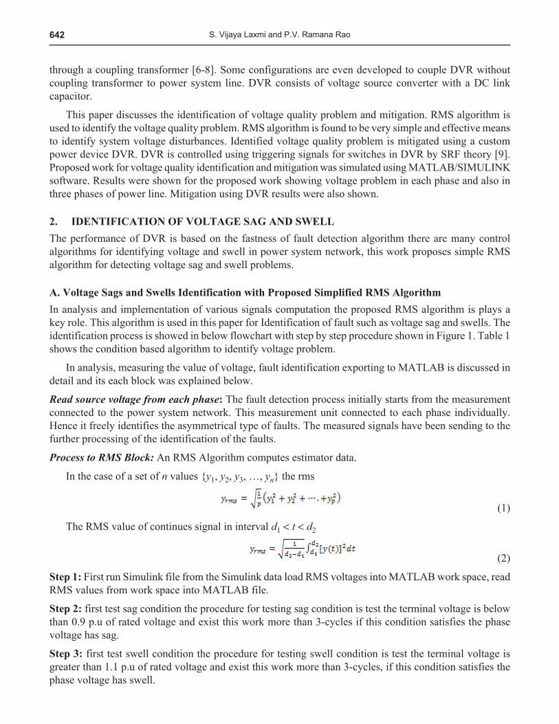
A. Voltage Sags and Swells Identification with Proposed Simplified RMS AlgorithmIn analysis and implementation of various signals computation the proposed RMS algorithm is plays a key role. This algorithm is used in this paper for Identification of fault such as voltage sag and swells. The identification process is showed in below flowchart with step by step procedure shown in Figure 1. Table 1 shows the condition based algorithm to identify voltage problem.
In analysis, measuring the value of voltage, fault identification exporting to MATLAB is discussed in detail and its each block was explained below.
Read source voltage from each phase: The fault detection process initially starts from the measurement connected to the power system network. This measurement unit connected to each phase individually. Hence it freely identifies the asymmetrical type of faults. The measured signals have been sending to the further processing of the identification of the faults.
Process to RMS Block: An RMS Algorithm computes estimator data.
In the case of a set of n values {y1, y2, y3, …, yn} the rms
(1)
The RMS value of continues signal in interval d1 < t < d2
(2)
Step 1: First run Simulink file from the Simulink data load RMS voltages into MATLAB work space, read RMS values from work space into MATLAB file.
Step 2: first test sag condition the procedure for testing sag condition is test the terminal voltage is below than 0.9 p.u of rated voltage and exist this work more than 3-cycles if this condition satisfies the phase voltage has sag.
Step 3: first test swell condition the procedure for testing swell condition is test the terminal voltage is greater than 1.1 p.u of rated voltage and exist this work more than 3-cycles, if this condition satisfies the phase voltage has swell.
643Voltage Disturbances Identification and Mitigation using SRF Controlled DVR in Distribution System
Step 4: test for sag and swell: In this we have to follow procedure in step 2 and step 3.
Step 5: Display the result.
Figure 1: Flow chart for Fault Identification using RMS analysis
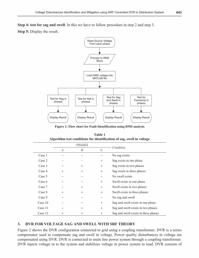
Table 1 Algorithm test conditions for identification of sag, swell in voltage
PHASESCondition
A B CCase 1 - - - No sag existsCase 2 - - + Sag exists in one phaseCase 3 - + + Sag exists in two phasesCase 4 + + + Sag exists in three phasesCase 5 - - - No swell existsCase 6 - - + Swell exists in one phaseCase 7 - + + Swell exists in two phasesCase 8 + + + Swell exists in three phasesCase 9 - - - No sag and swellCase 10 - - + Sag and swell exists in one phaseCase 11 - + + Sag and swell exists in two phasesCase 12 + + + Sag and swell exists in three phases
DVR FOR VOLTAGE SAG AND SWELL WITH SRF THEORY3. Figure 2 shows the DVR configuration connected to grid using a coupling transformer. DVR is a series compensator used to compensate sag and swell in voltage. Power quality disturbances in voltage are compensated using DVR. DVR is connected to main line power system through a coupling transformer. DVR injects voltage in to the system and stabilizes voltage in power system to load. DVR consists of

644 S. Vijaya Laxmi and P.V. Ramana Rao
voltage source converter with a DC link voltage. By proper control of switches in voltage source converter, voltage is induced in to the power system to stabilize voltage at load side.
DVR Controlling Based On Synchronous Reference Frame Theory (SRF)Figure.3 Shows the Control Block Diagram of the DVR with SRF theory [7-8] .The Source Voltage Vs is sensed And give it as an input to the transformation block (abc/dq) And same source voltage (Vs) is given as an input to the PLL block .the PLL block generates sin,cos functions. This is given as an input to the inverse transformation block (abc/dq). The input transformation block results the Vd, Vq, and Vo information is compared with Vdact, Vqact and Voact which are the actual parameters the quadrature and Vo axis is compared with 0 p.u .the error generated is given as an input to the PID controller. The PID controller output is again given as an input to dq/abc block ,and PLL information is also given as an input to dq/abc block. This block gives us the pulse information which is given as an input to pwm generator and from that gate pulses are generated .those gate pulses are for inverter.
Figure 2: DVR Block Diagram
Figure 3: DVR Control Block Diagram based on SRF Theory
MATLAB/SIMULATION RESULTS AND DISCUSSION4. MATLAB software is used for identification problems like sag, swell ext. The DVR modeling is model using Simulink software the proposed simple SRF control generator the required gate pulses for DVR.

645Voltage Disturbances Identification and Mitigation using SRF Controlled DVR in Distribution System
A. Identification of Sag and SwellCase 1: Sag exists in 3 phase of the system.
Figure 4: Result showing sag present in 3 phases
Figure 4 shows the instantaneous 3-phase voltage during 3-phase fault and its corresponding RMS voltage, the depth of the sag due to 3-phase fault is 60% and duration of sag is 0.1 sec.Case 2: Swell exists in 3 phase of the system:
Figure 5: Result showing swell present in three phases
646 S. Vijaya Laxmi and P.V. Ramana Rao
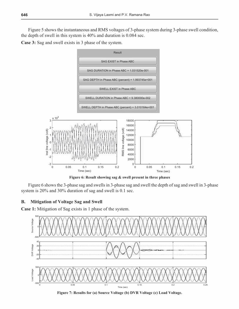
Figure 5 shows the instantaneous and RMS voltages of 3-phase system during 3-phase swell condition, the depth of swell in this system is 40% and duration is 0.084 sec.Case 3: Sag and swell exists in 3 phase of the system.
Figure 6: Result showing sag & swell present in three phases
Figure 6 shows the 3-phase sag and swells in 3-phase sag and swell the depth of sag and swell in 3-phase system is 20% and 30% duration of sag and swell is 0.1 sec.
B. Mitigation of Voltage Sag and SwellCase 1: Mitigation of Sag exists in 1 phase of the system.
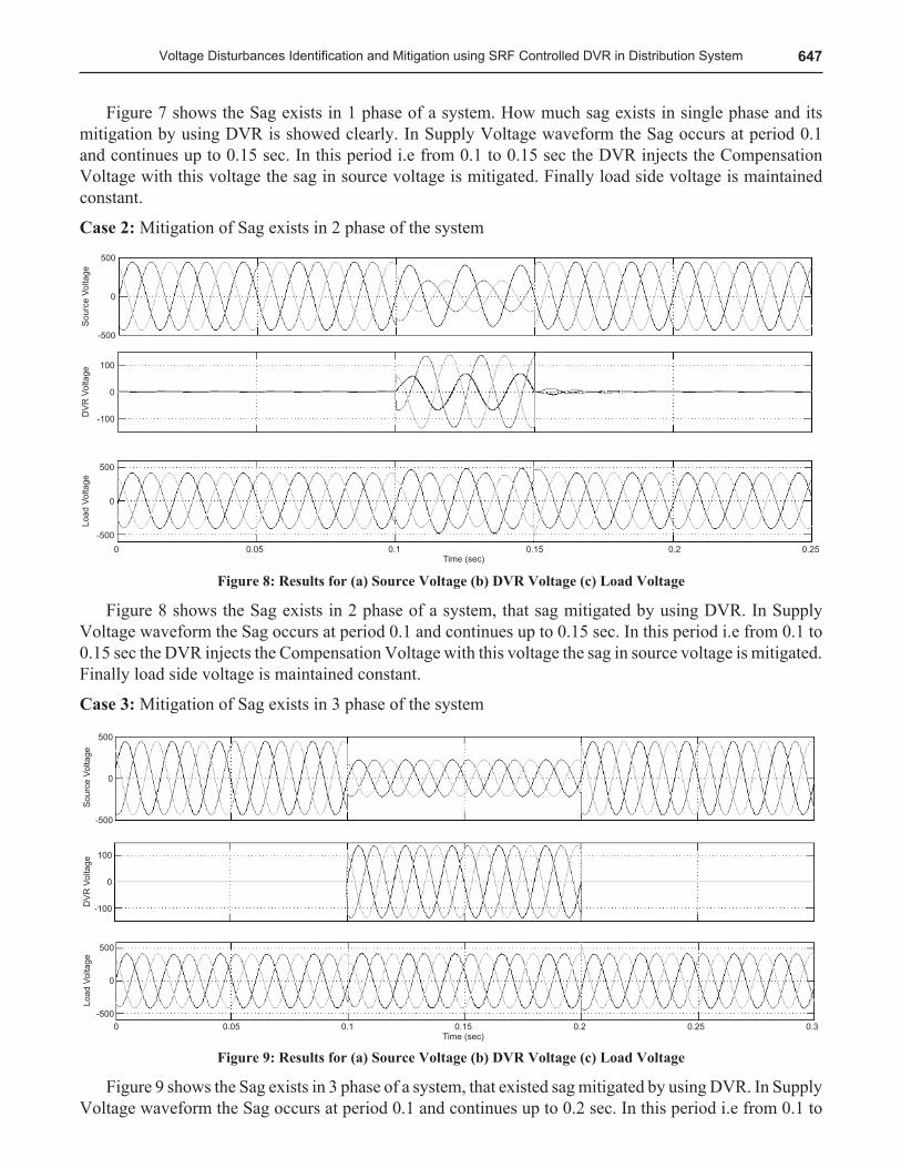
Figure 7: Results for (a) Source Voltage (b) DVR Voltage (c) Load Voltage.
647Voltage Disturbances Identification and Mitigation using SRF Controlled DVR in Distribution System
Figure 7 shows the Sag exists in 1 phase of a system. How much sag exists in single phase and its mitigation by using DVR is showed clearly. In Supply Voltage waveform the Sag occurs at period 0.1 and continues up to 0.15 sec. In this period i.e from 0.1 to 0.15 sec the DVR injects the Compensation Voltage with this voltage the sag in source voltage is mitigated. Finally load side voltage is maintained constant.
Case 2: Mitigation of Sag exists in 2 phase of the system
Figure 8: Results for (a) Source Voltage (b) DVR Voltage (c) Load Voltage
Figure 8 shows the Sag exists in 2 phase of a system, that sag mitigated by using DVR. In Supply Voltage waveform the Sag occurs at period 0.1 and continues up to 0.15 sec. In this period i.e from 0.1 to 0.15 sec the DVR injects the Compensation Voltage with this voltage the sag in source voltage is mitigated. Finally load side voltage is maintained constant.
Case 3: Mitigation of Sag exists in 3 phase of the system
Figure 9: Results for (a) Source Voltage (b) DVR Voltage (c) Load Voltage
Figure 9 shows the Sag exists in 3 phase of a system, that existed sag mitigated by using DVR. In Supply Voltage waveform the Sag occurs at period 0.1 and continues up to 0.2 sec. In this period i.e from 0.1 to
648 S. Vijaya Laxmi and P.V. Ramana Rao
0.2 sec the DVR injects the Compensation Voltage with this voltage the sag in source voltage is mitigated. Finally load side voltage is maintained constant.
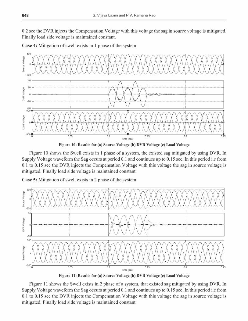
Case 4: Mitigation of swell exists in 1 phase of the system
Figure 10: Results for (a) Source Voltage (b) DVR Voltage (c) Load Voltage
Figure 10 shows the Swell exists in 1 phase of a system, the existed sag mitigated by using DVR. In Supply Voltage waveform the Sag occurs at period 0.1 and continues up to 0.15 sec. In this period i.e from 0.1 to 0.15 sec the DVR injects the Compensation Voltage with this voltage the sag in source voltage is mitigated. Finally load side voltage is maintained constant.
Case 5: Mitigation of swell exists in 2 phase of the system
Figure 11: Results for (a) Source Voltage (b) DVR Voltage (c) Load Voltage
Figure 11 shows the Swell exists in 2 phase of a system, that existed sag mitigated by using DVR. In Supply Voltage waveform the Sag occurs at period 0.1 and continues up to 0.15 sec. In this period i.e from 0.1 to 0.15 sec the DVR injects the Compensation Voltage with this voltage the sag in source voltage is mitigated. Finally load side voltage is maintained constant.
649Voltage Disturbances Identification and Mitigation using SRF Controlled DVR in Distribution System
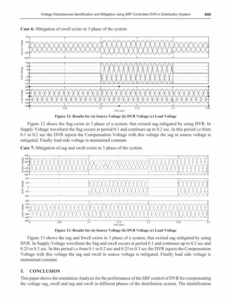
Case 6: Mitigation of swell exists in 3 phase of the system
Figure 12: Results for (a) Source Voltage (b) DVR Voltage (c) Load Voltage
Figure 12 shows the Sag exists in 3 phase of a system, that existed sag mitigated by using DVR. In Supply Voltage waveform the Sag occurs at period 0.1 and continues up to 0.2 sec. In this period i.e from 0.1 to 0.2 sec the DVR injects the Compensation Voltage with this voltage the sag in source voltage is mitigated. Finally load side voltage is maintained constant.
Case 7: Mitigation of sag and swell exists in 3 phase of the system.
Figure 13: Results for (a) Source Voltage (b) DVR Voltage (c) Load Voltage
Figure 13 shows the sag and Swell exists in 3 phase of a system, that existed sag mitigated by using DVR. In Supply Voltage waveform the Sag and swell occurs at period 0.1 and continues up to 0.2 sec and 0.25 to 0.3 sec. In this period i.e from 0.1 to 0.2 sec and 0.25 to 0.3 sec the DVR injects the Compensation Voltage with this voltage the sag and swell in source voltage is mitigated. Finally load side voltage is maintained constant.
CONCLUSION5. This paper shows the simulation Analysis for the performance of the SRF control of DVR for compensating the voltage sag, swell and sag and swell in different phases of the distribution system. The identification
650 S. Vijaya Laxmi and P.V. Ramana Rao
of sag swell and sag swell is done by using RMS algorithm .The proposed SRF control of DVR is have an capable of compensating the various voltage disturbances like single phase, two phase and three phase sag and swell. Identification and Mitigation of sag and swell in various conditions are tested for the performance capability of DVR through extensive simulation and results are presented. Comparative analysis was not presented but only the voltage quality problem is mitigated using DVR with SRF theory.
ReferencesA. Latheef, M. Negnevitsky and V. Faybisovich, “Voltage sag source location identification,” Electricity Distribution - Part 1, 1. 2009. CIRED2009. 20th International Conference and Exhibition on, Prague, Czech Republic, 2009, pp. 1-4.U.T. Patil; A.R. Thorat; “Hysteresis Voltage Control Technique in Dynamic Voltage Restorer for Power Quality 2. Improvement” 978-1-4673-6150-7/13/$31.00 ©2013 IEEE.Lim PK, Dor DS. Understanding and resolving voltage sag related problems for sensitive industrial customers. 3. IEEE Power Eng Soc Winter Meet 20011;4:2886-90.Y.W. Li, D.M. Vilathgamuwa, F. Blaabjerg, and P.C. Loh, “A robust control scheme for medium-voltage-level DVR 4. implementation,” IEEE Trans. Ind. Electron., Vol. 54, No. 4, pp. 2249-2261, Aug. 2007.A.K. Sadigh and K.M. Smedley, “Review of voltage compensation methods in dynamic voltage restorer (DVR),” in 5. Proc. IEEE Power Energy Soc. Gen. Meet., Jul. 2012, pp. 1-8.Dr. T. Ruben; Deva Prakash; G. Justin; Sunil Dhas; “A Novel approach for Voltage Sag Mitigation Using FACTS Device 6. Interline Dynamic Voltage Restorer” 978-1-4244-8679- 3/11/$26.00©2011IEEE”.A. Y. Goharrizi, S.H. Hosseini, M. Sabahi, and G.B. Gharehpetian, “Three-phase HFL-DVR with independently controlled 7. phases,” IEEE Trans. Power Electron., Vol. 27, No. 4, pp. 1706-1718, Apr. 2012.E. Babaei, M. Farhadi Kangarlu, ―Voltage quality improvement by a dynamic voltage restorer based on a direct three-8. phase converter with fictitious DC link, IET Gener. Transm. Distrib., 2011, Vol. 5, Iss. 8, pp. 814-823.P. Kanjiya, B. Singh, A. Chandra, and K. Al-Haddad, “SRF theory revisited to control self-supported dynamic voltage 9. restorer (DVR) for unbalanced and nonlinear loads,” IEEE Trans. Ind. Appl., Vol. 49, No. 5, pp. 2330-2340, Sep./Oct. 2013.Rating and Design Issues of DVR Injection Transformer.