Embed Size (px)
Citation preview
Power Magnetics Design and Measurement of Power MagneticsCharles R S lli an h l lli @d t th dCharles R. Sullivan, [email protected] 2011
Dartmouth Magnetics and PowerElectronics Research Group
1http://power.engineering.dartmouth.edu
High-performance high-frequency po er magnetic designpower magnetic design
Select winding configuration Select winding configuration. Approximate analytical models for winding loss,
core loss, and thermal resistance., Co-optimize magnetics design with circuit design:
Switching frequency Inductance value Magnetic component geometric parameters
Goal: efficiency vs size tradeoff (thermal constraint) Goal: efficiency vs. size tradeoff (thermal constraint) Fine tune design with finite-element analysis.
power.thayer.dartmouth.edu 2
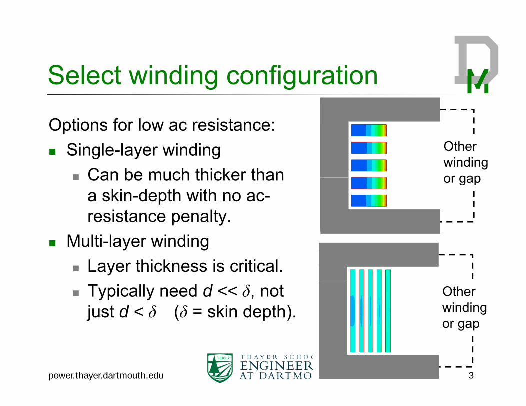
Select winding configurationSelect winding configuration
Options for low ac resistance:Options for low ac resistance: Single-layer winding
Can be much thicker than
Otherwinding or gap Can be much thicker than
a skin-depth with no ac-resistance penalty.
or gap
Multi-layer winding Layer thickness is critical. Typically need d << δ, not
just d < δ (δ = skin depth).Otherwinding or gap
power.thayer.dartmouth.edu 3
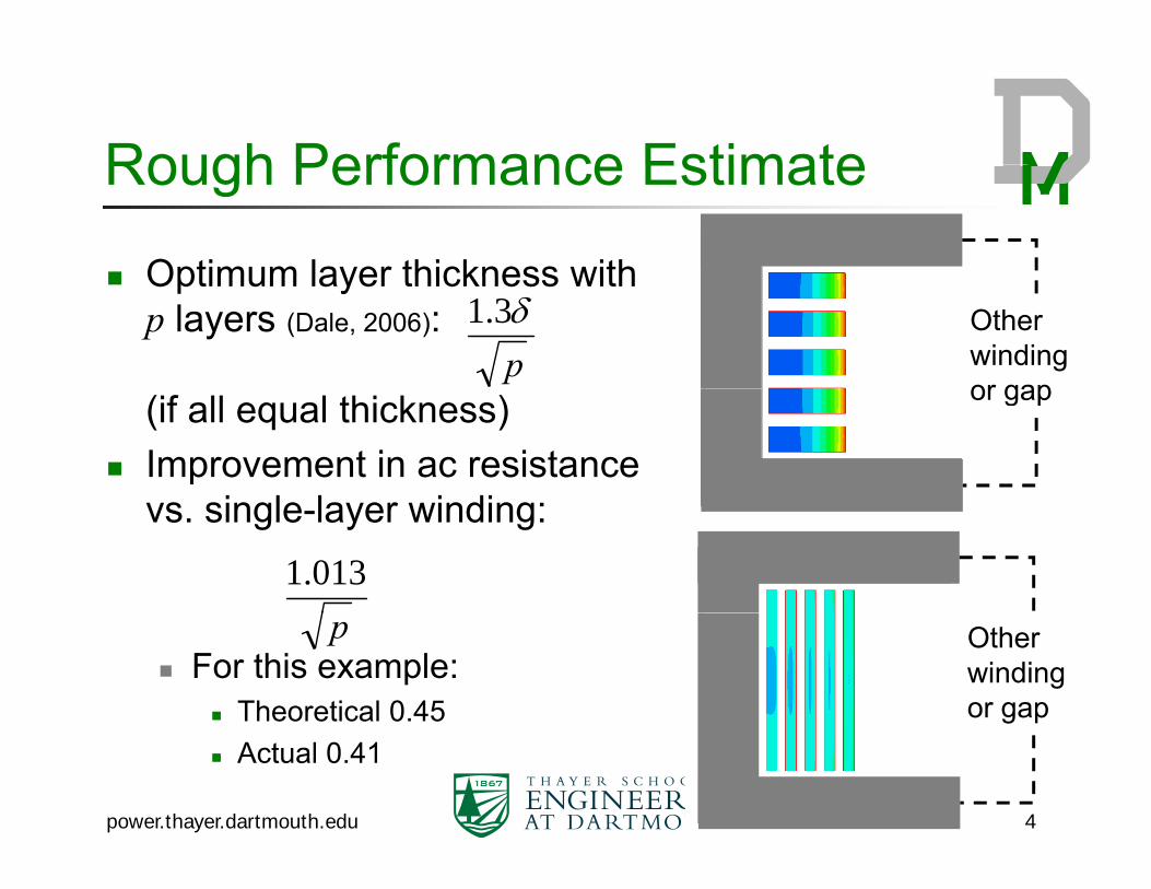
Rough Performance EstimateRough Performance Estimate
Optimum layer thickness with Optimum layer thickness with p layers (Dale, 2006): Other
winding or gap
p3.1
(if all equal thickness) Improvement in ac resistance
i l l i di
or gap
vs. single-layer winding:013.1
For this example: Theoretical 0.45
Otherwinding or gap
p
Actual 0.41
power.thayer.dartmouth.edu 4
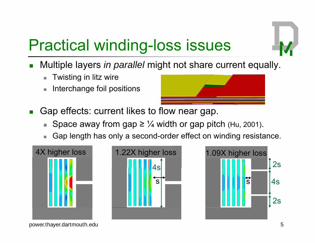
Practical winding loss issuesPractical winding-loss issues Multiple layers in parallel might not share current equally.
T isting in lit ire Twisting in litz wire Interchange foil positions
Gap effects: current likes to flow near gap. Space away from gap ≥ ¼ width or gap pitch (Hu, 2001). Gap length has only a second-order effect on winding resistance Gap length has only a second order effect on winding resistance.
4X higher loss 1.22X higher loss
4s
1.09X higher loss2s4s
s 4ss
2
power.thayer.dartmouth.edu 5
2s
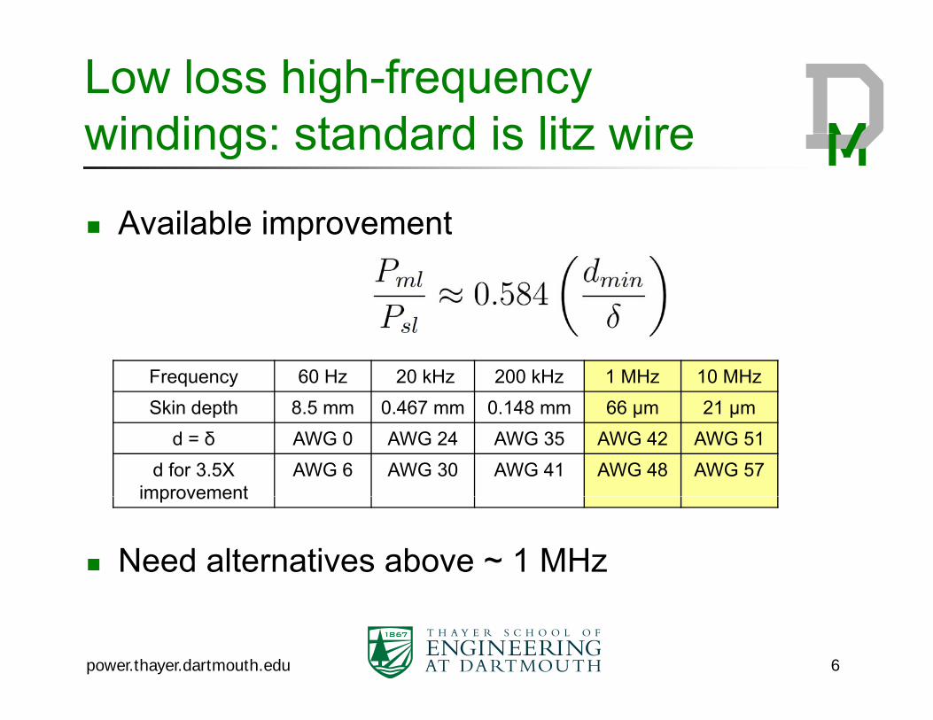
Low loss high-frequency windings: standard is litz wirewindings: standard is litz wire
Available improvement Available improvement
Frequency 60 Hz 20 kHz 200 kHz 1 MHz 10 MHzSkin depth 8 5 mm 0 467 mm 0 148 mm 66 μm 21 μmSkin depth 8.5 mm 0.467 mm 0.148 mm 66 μm 21 μm
d = δ AWG 0 AWG 24 AWG 35 AWG 42 AWG 51d for 3.5X
improvementAWG 6 AWG 30 AWG 41 AWG 48 AWG 57
Need alternatives above ~ 1 MHz
improvement
power.thayer.dartmouth.edu 6
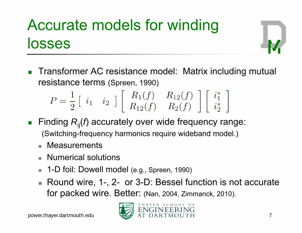
Accurate models for winding losseslosses
Transformer AC resistance model: Matrix including mutual Transformer AC resistance model: Matrix including mutual resistance terms (Spreen, 1990)
Finding Rij(f) accurately over wide frequency range:(S it hi f h i i id b d d l )(Switching-frequency harmonics require wideband model.) Measurements Numerical solutions 1-D foil: Dowell model (e.g., Spreen, 1990)
Round wire, 1-, 2- or 3-D: Bessel function is not accurate f k d i B ttfor packed wire. Better: (Nan, 2004, Zimmanck, 2010).
power.thayer.dartmouth.edu 7

Modeling Core LossModeling Core Loss
Thin film alloys and laminations: Thin-film alloys and laminations: Classical eddy-current
At high frequency with thin At high frequency, with thin dielectric, capacitance may allow additional eddy current (Yao 2009)
Hysteresis loss Anomalous loss: model based on domain-wall
motion (B t tti 1998)motion. (Bertotti, 1998)
Ferrites: Steinmetz curve fit to measured data if excitation is sinusoidaldata….if excitation is sinusoidal.
power.thayer.dartmouth.edu 8
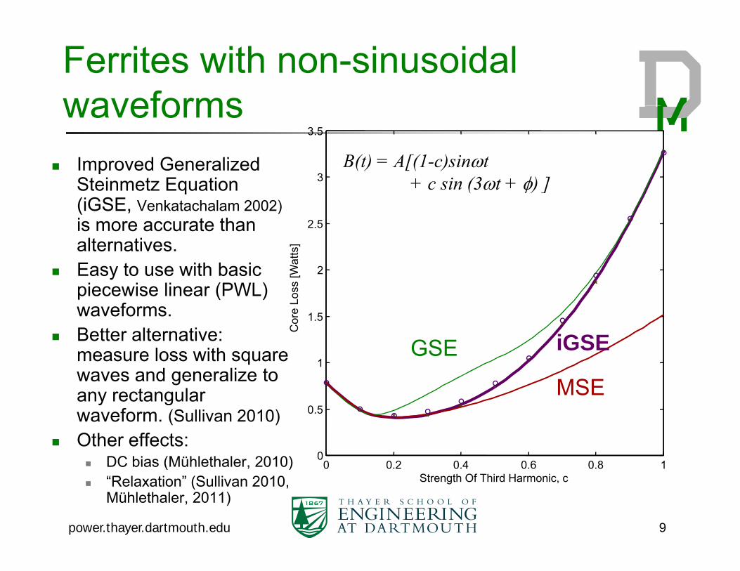
Ferrites with non-sinusoidal waveforms
3
3.5waveforms
Improved Generalized St i t E ti
B(t) = A[(1-c)sinti (3 ) ]
2.5
3
s]
Steinmetz Equation (iGSE, Venkatachalam 2002)is more accurate than alternatives.
+ c sin (3t + ) ]
1.5
2
ore
Loss
[Wat
tsalternatives. Easy to use with basic
piecewise linear (PWL) waveforms.
1
Co
Better alternative: measure loss with square waves and generalize to any rectangular MSE
GSE iGSE
0 0 2 0 4 0 6 0 8 10
0.5any rectangular waveform. (Sullivan 2010)
Other effects: DC bias (Mühlethaler, 2010)
MSE
power.thayer.dartmouth.edu 9
0 0.2 0.4 0.6 0.8 1Strength Of Third Harmonic, c
DC bias (Mühlethaler, 2010) “Relaxation” (Sullivan 2010,
Mühlethaler, 2011)
DesignDesign Easy way to get a mediocre inductor:
Large L for small ripple. Can tolerate large Rac with small ripple—wind for
l d i tlow dc resistance. Saturation is more important than core loss (see
Pollock, 2011 for a model)o oc , 0 o a ode ) Path to a better inductor:
Optimize L and fswitching with inductor design.g
→ Lower L, higher ripple Requires low Rac … and requires circuit tricks for
power.thayer.dartmouth.edu 10
q ac qlight-load efficiency.
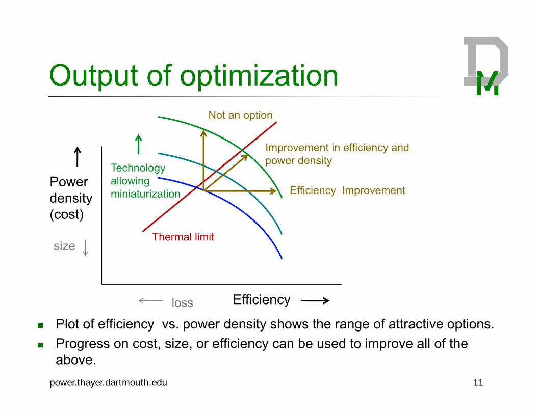
Output of optimizationOutput of optimizationNot an option
PowerTechnologyallowing
Improvement in efficiency and power density
Power density(cost)
allowingminiaturization Efficiency Improvement
Th l li itsize
Thermal limit
Efficiencyloss
Plot of efficiency vs. power density shows the range of attractive options.
power.thayer.dartmouth.edu 11
Progress on cost, size, or efficiency can be used to improve all of the above.
Options to considerOptions to consider
Integrate multiple components (e g inductor Integrate multiple components (e.g. inductor, transformer) on a single core.
Circuit designs that utilize coupled magnetic components.
Hybrid windings for components with ac and dc or high-frequency and low-frequency current (e g litzhigh-frequency and low-frequency current (e.g., litzwire and solid wire) (Valchev, 2005; Schaef 2012).
Aluminum wire: enables lower loss than copper under ppweight or cost constraints (but not under size constraints). (Sullivan, 2008)
power.thayer.dartmouth.edu 12
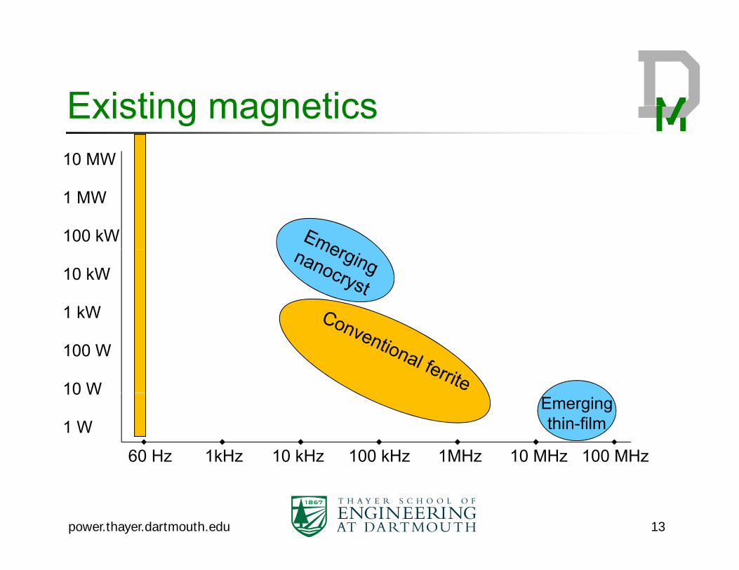
Existing magneticsExisting magnetics10 MW
1 MW
100 kW
10 kW
1 kW
100 W
10 W
60 Hz 1kHz 10 kHz 100 kHz 1MHz 10 MHz 100 MHz
10 W
1 WEmergingthin-film
power.thayer.dartmouth.edu 13
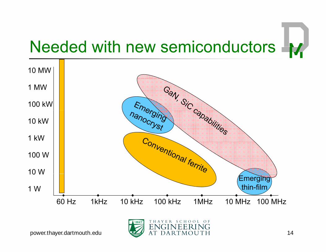
Needed with new semiconductorsNeeded with new semiconductors10 MW
1 MW
100 kW
10 kW
1 kW
100 W
10 W
60 Hz 1kHz 10 kHz 100 kHz 1MHz 10 MHz 100 MHz
10 W
1 WEmergingthin-film
power.thayer.dartmouth.edu 14
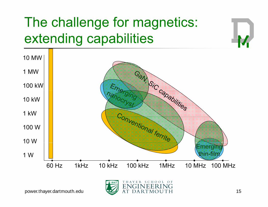
The challenge for magnetics: extending capabilitiesextending capabilities10 MW
1 MW
100 kW
10 kW
1 kW
100 W
10 W
60 Hz 1kHz 10 kHz 100 kHz 1MHz 10 MHz 100 MHz
10 W
1 WEmergingthin-film
power.thayer.dartmouth.edu 15
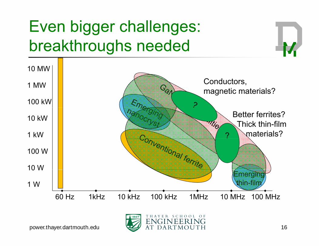
Even bigger challenges:breakthroughs neededbreakthroughs needed10 MW
1 MW
100 kW
Conductors, magnetic materials?
10 kW
1 kW ?
Better ferrites?Thick thin-film
materials?
100 W
10 W
60 Hz 1kHz 10 kHz 100 kHz 1MHz 10 MHz 100 MHz
10 W
1 WEmergingthin-film
power.thayer.dartmouth.edu 16
Measurement ChallengesMeasurement Challenges
Accurate loss measurement of low loss Accurate loss measurement of low-loss components
Nonlinearity of core loss Nonlinearity of core loss Connecting instruments with low residual
impedanceimpedance Separating core and winding losses Magnetic material measurement without Magnetic material measurement without
making components
power.thayer.dartmouth.edu 17
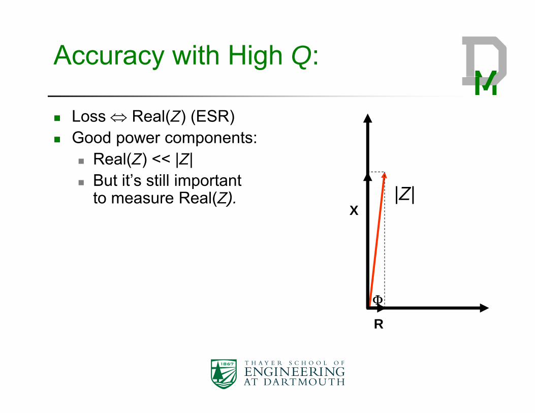
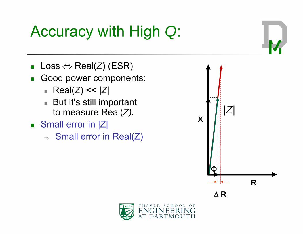
Accuracy with High Q:
Loss Real(Z) (ESR) Good power components:
Real(Z) << |Z| But it’s still important
X|Z|
But it s still important to measure Real(Z).
R
Accuracy with High Q:
Loss Real(Z) (ESR) Good power components:
Real(Z) << |Z| But it’s still important
X|Z|
But it s still important to measure Real(Z).
Small error in |Z| Small error in Real(Z)
R
R
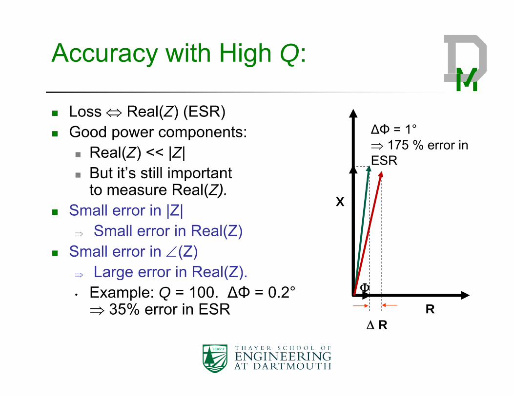
Accuracy with High Q:
Loss Real(Z) (ESR)∆Φ = 1° 175 % error in ESR
Good power components: Real(Z) << |Z| But it’s still important
X
But it s still important to measure Real(Z).
Small error in |Z| Small error in Real(Z)
Small error in (Z) Large error in Real(Z)
R R
Large error in Real(Z).• Example: Q = 100. ∆Φ = 0.2° 35% error in ESR
R
Accurate measurements with high Qhigh-Q
Use an instrument with excellent phase accuracy Use an instrument with excellent phase accuracy. Compensate with a low-loss capacitor to “tune out”
indutance (power factor correction) (Han 2008, Mu 2010)
Polypropylene/porcelain/mica/air May still need to measure and correct for
capacitor ESR but at least it’s linear (exceptcapacitor ESR, but at least it’s linear (except ferroelectrics).
power.thayer.dartmouth.edu 21
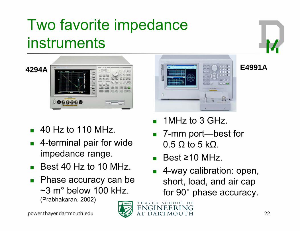
Two favorite impedance instrumentsinstruments4294A E4991A4294A
40 Hz to 110 MHz 1MHz to 3 GHz.
b f 40 Hz to 110 MHz. 4-terminal pair for wide
impedance range.
7-mm port—best for 0.5 Ω to 5 kΩ.
Best ≥10 MHz Best 40 Hz to 10 MHz. Phase accuracy can be
3 ° b l 100 kH
Best ≥10 MHz. 4-way calibration: open,
short, load, and air cap ~3 m° below 100 kHz. (Prabhakaran, 2002)
power.thayer.dartmouth.edu 22
for 90° phase accuracy.
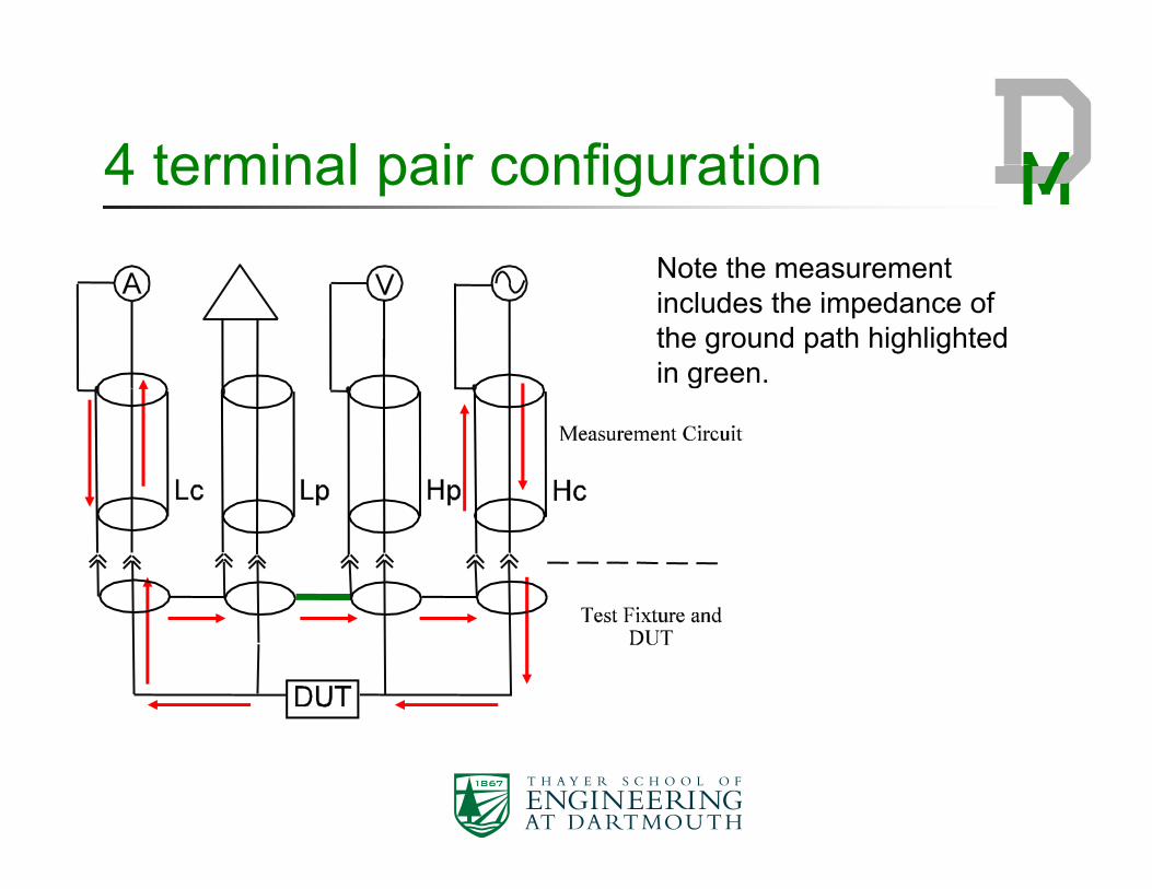
4 terminal pair configuration4 terminal pair configurationNote the measurementNote the measurement includes the impedance of the ground path highlighted in green.
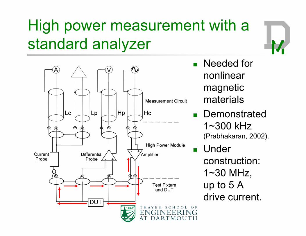
High power measurement with a standard analyzerstandard analyzer
Needed for linonlinear
magnetic materials
Demonstrated 1~300 kHz(Prabhakaran, 2002).
Under construction:construction: 1~30 MHz, up to 5 A drive current.
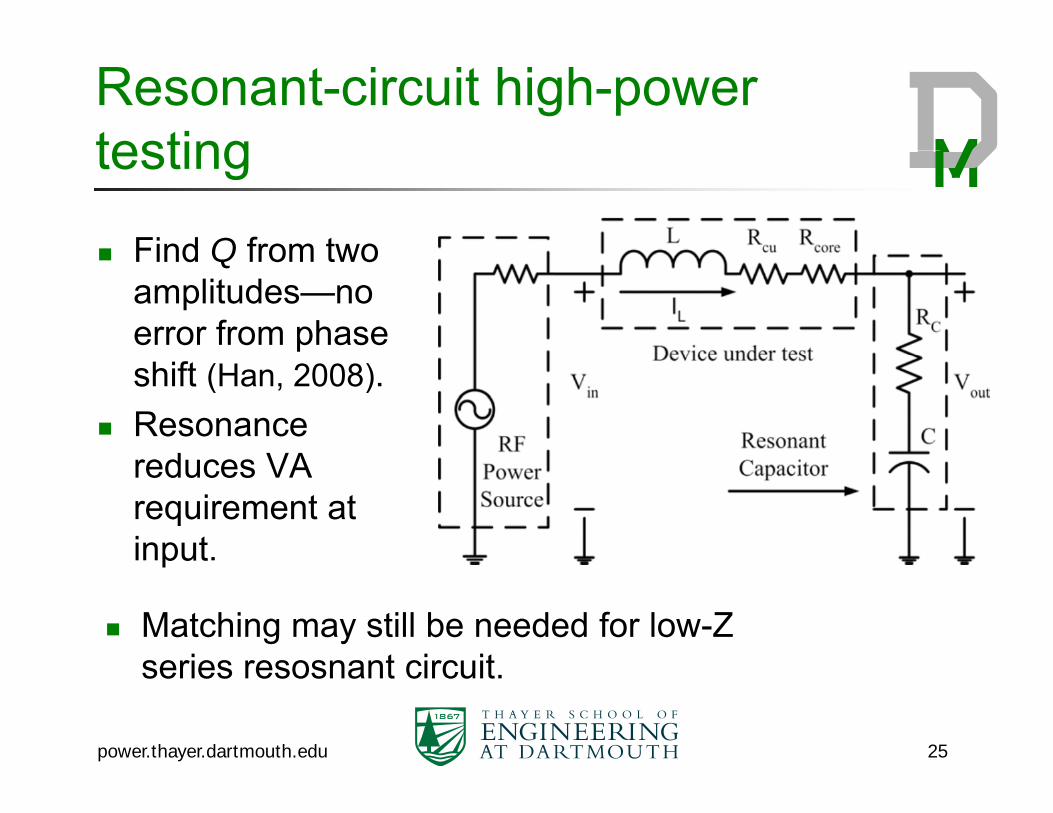
Resonant-circuit high-power testingtesting
Find Q from two Find Q from two amplitudes—no error from phase shift (Han, 2008).
Resonance d VAreduces VA
requirement at input.put
Matching may still be needed for low-Z series resosnant circuit
power.thayer.dartmouth.edu 25
series resosnant circuit.
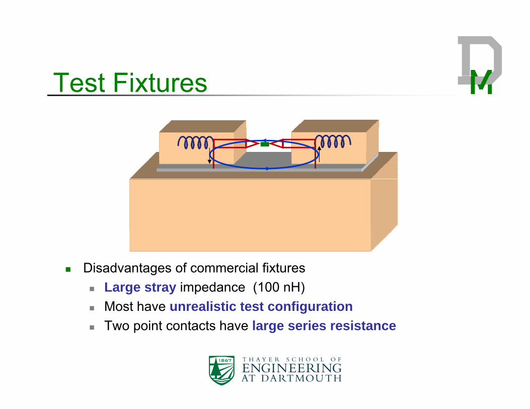
T t Fi tTest Fixtures
Disadvantages of commercial fixtures( ) Large stray impedance (100 nH)
Most have unrealistic test configuration Two point contacts have large series resistance
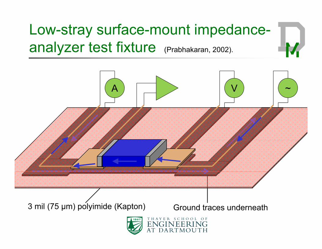
Low-stray surface-mount impedance-analyzer test fixtureanalyzer test fixture (Prabhakaran, 2002).
A V ~
Ground traces underneath3 mil (75 µm) polyimide (Kapton)
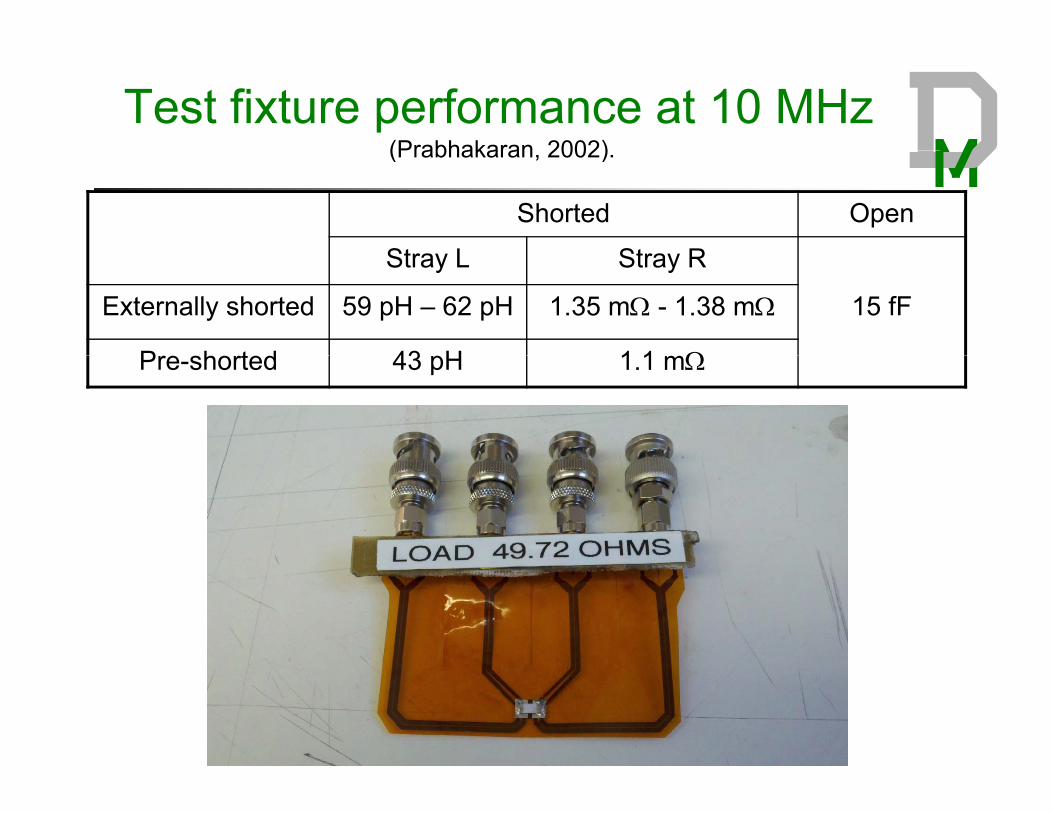
Test fixture performance at 10 MHz(Prabhakaran 2002)(Prabhakaran, 2002).
Shorted Open
St L St RStray L Stray R
Externally shorted 59 pH – 62 pH 1.35 m - 1.38 m 15 fF
P h t d 43 H 1 1 Pre-shorted 43 pH 1.1 m
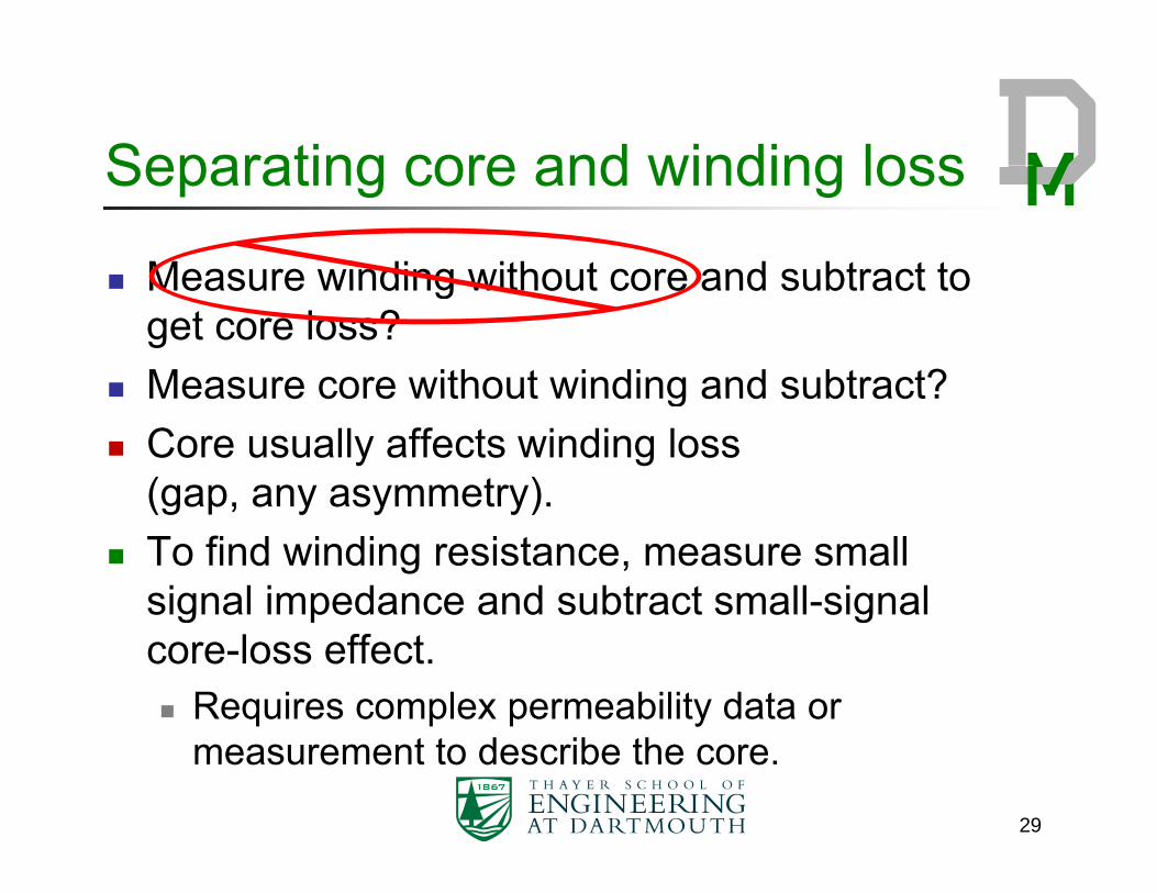
Separating core and winding lossSeparating core and winding loss
Measure winding without core and subtract to Measure winding without core and subtract to get core loss?
Measure core without winding and subtract? Measure core without winding and subtract? Core usually affects winding loss
(gap, any asymmetry).(gap, any asymmetry). To find winding resistance, measure small
signal impedance and subtract small-signal g p gcore-loss effect. Requires complex permeability data or
measurement to describe the core.
29
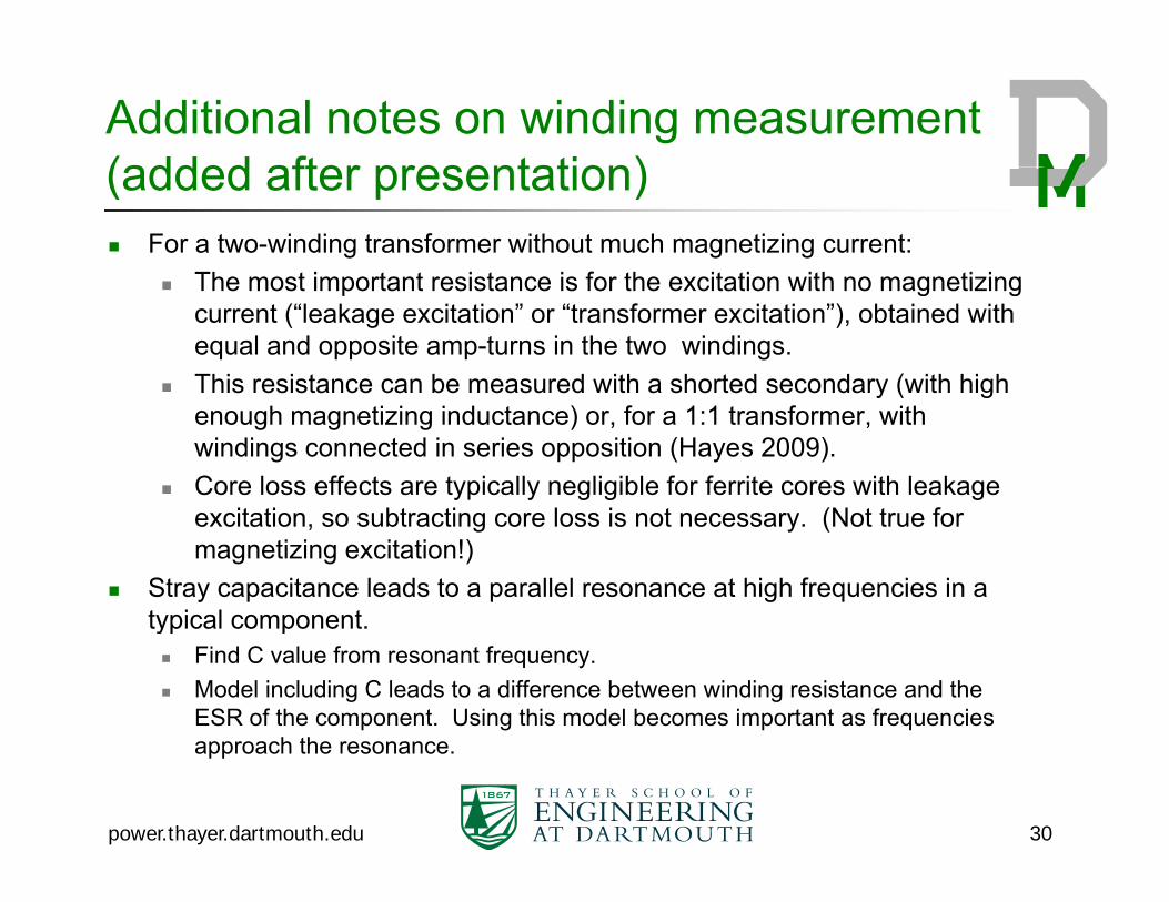
Additional notes on winding measurement (added after presentation)(added after presentation) For a two-winding transformer without much magnetizing current:
The most important resistance is for the excitation with no magnetizing The most important resistance is for the excitation with no magnetizing current (“leakage excitation” or “transformer excitation”), obtained with equal and opposite amp-turns in the two windings.
This resistance can be measured with a shorted secondary (with high y ( genough magnetizing inductance) or, for a 1:1 transformer, with windings connected in series opposition (Hayes 2009).
Core loss effects are typically negligible for ferrite cores with leakage it ti bt ti l i t (N t t fexcitation, so subtracting core loss is not necessary. (Not true for
magnetizing excitation!) Stray capacitance leads to a parallel resonance at high frequencies in a
typical componenttypical component. Find C value from resonant frequency. Model including C leads to a difference between winding resistance and the
ESR of the component. Using this model becomes important as frequencies approach the resonance.
power.thayer.dartmouth.edu 30

Typical procedure to measure ac resistance of i d t i di ( dd d ft t ti )an inductor winding (added after presentation)
Calibrate analyzer with text fixture.Consider using averaging over the same frequency range to be Consider using averaging over the same frequency range to be used in the impedance measurement.
Measure Z(f), typically using series inductance and series resistance as coordinates.
Find resonant frequency (which may be outside the range initially scanned in the impedance measurement) and calculate capacitance.
Measure impedance with closed gap (zero gap) to obtain small-signal core characteristic. If ESR measured in this configuration is much larger than ESR measured with a gap, the loss is mostly due to core loss. If not, see the next slide for alternatives to obtain core loss.The small signal core loss characteristic can be used to calculate the The small-signal core loss characteristic can be used to calculate the component of the ESR attributable to the core loss. One way to do this is to use the fact that the parallel resistance due to core loss is constant independent of gap length. p g p g
Winding resistance is obtained by subtracting core ESR and correcting for C.
power.thayer.dartmouth.edu 31
Core loss measurements: small signal and large signalsmall-signal and large-signal
With a closed core (ideally with no gap):With a closed core (ideally with no gap): Classic two-winding measurement:
Small-signal or large-signal Beware of capacitance to other winding or core, and of
mutual resistance appearing as core loss.Can use capacitor to make high Q measurement more Can use capacitor to make high-Q measurement more accurate (Mu, 2010) (important for low-perm cores)
Subtract winding resistance (Valchev, 2005, Han 2008): Known via modeling. Litz wire in range where it’s independent of frequency.
M d Measured…
power.thayer.dartmouth.edu 32
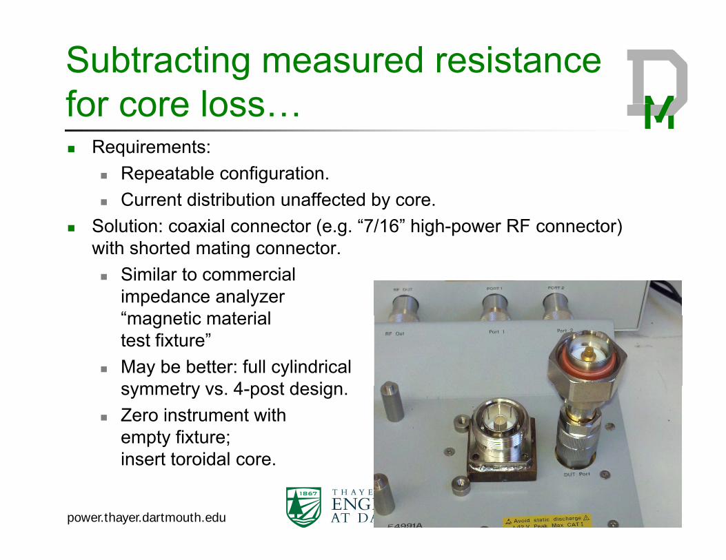
Subtracting measured resistance for core lossfor core loss… Requirements:
Repeatable configuration Repeatable configuration. Current distribution unaffected by core.
Solution: coaxial connector (e.g. “7/16” high-power RF connector) with shorted mating connectorwith shorted mating connector. Similar to commercial
impedance analyzer“magnetic materialmagnetic material test fixture”
May be better: full cylindrical symmetry vs 4 post designsymmetry vs. 4-post design.
Zero instrument with empty fixture; insert toroidal coreinsert toroidal core.
power.thayer.dartmouth.edu 33
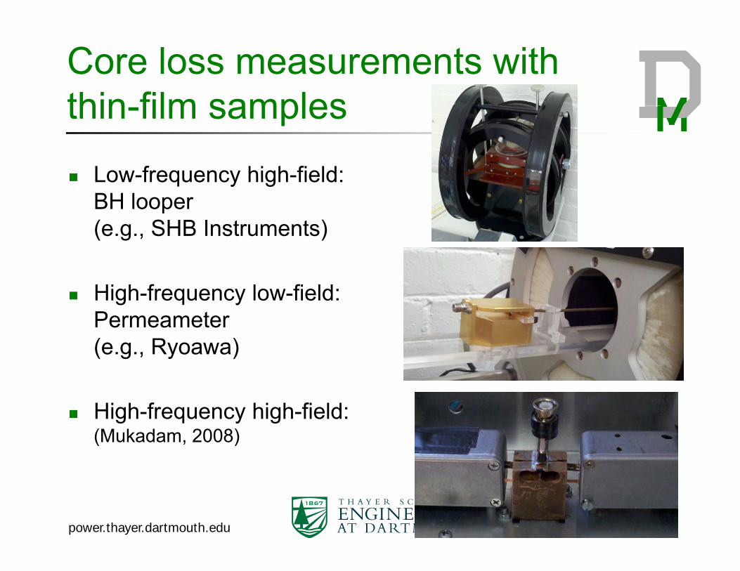
Core loss measurements with thin film samplesthin-film samples
Low-frequency high-field: Low frequency high field: BH looper(e.g., SHB Instruments)
High-frequency low-field:PermeameterPermeameter(e.g., Ryoawa)
High-frequency high-field:(Mukadam, 2008)
power.thayer.dartmouth.edu 34
References Giorgio Bertotti, Hysteresis in magnetism: for physicists, materials scientists, and engineers, Academic Press, ISBN 978-0120932702,
19981998. M.E. Dale and C.R. Sullivan, "Comparison of Single-Layer and Multi-Layer Windings with Physical Constraints or Strong
Harmonics," IEEE International Symposium on Industrial Electronics, 2006. doi: 10.1109/ISIE.2006.295688 Yehui Han, G. Cheung, An Li, C.R. Sullivan, D.J. Perreault, "Evaluation of magnetic materials for very high frequency power
applications," IEEE Power Electronics Specialists Conference (PESC), 2008. doi: 10.1109/PESC.2008.4592628 J. G. Hayes, D. Cashman, M.G. Egan, T. O'Donnell, Ningning Wang, "Comparison of Test Methods for Characterization of High-
L k T Wi di T f " IEEE T ti I d t A li ti l 45 5 1729 1741 2009Leakage Two-Winding Transformers," , IEEE Transactions on Industry Applications , vol.45, no.5, pp.1729-1741, 2009doi: 10.1109/TIA.2009.2027549
Jiankun Hu, C.R. Sullivan. "AC Resistance of Planar Power Inductors and the Quasidistributed Gap Technique." IEEE Transactions on Power Electronics, 16(4), July 2001, pp. 558 -567.
Mingkai Mu, Qiang Li; D. Gilham, D.; F.C. Lee, K.D.T. Ngo, "New core loss measurement method for high frequency magnetic materials," IEEE Energy Conversion Congress and Exposition (ECCE), 2010. doi: 10.1109/ECCE.2010.5618454
J. Muhlethaler, J. Biela, J.W. Kolar, and A. Ecklebe, "Core losses under DC bias condition based on Steinmetz parameters,"International Power Electronics Conference (IPEC), 2010. doi: 10.1109/IPEC.2010.5542385
J. Muhlethaler, J. Biela, J.W. Kolar, and A. Ecklebe,, "Improved core loss calculation for magnetic components employed in power electronic system," IEEE Applied Power Electronics Conference and Exposition (APEC), 2011. doi: 10.1109/APEC.2011.5744829
H. Mukadam, C.R. Sullivan and S. Prabhakaran, “A High-Field High-Frequency Permeance Meter for Thin-Film Materials,” IEEE Power Electronics Specialists’ Conference, 2008.
Xi Nan and C. R. Sullivan, “Simplified High-Accuracy Calculation of Eddy-Current Losses in Round-Wire Windings.” IEEE Power Electronics Specialists Conference, 2004.
S. Prabhakaran and C.R. Sullivan, "Impedance-analyzer measurements of high-frequency power passives: techniques for high power and low impedance," IEEE 37th IAS Annual Meeting, 2002. doi: 10.1109/IAS.2002.1042734
C. Schaef and C.R. Sullivan, “Inductor Design for Low Loss with Complex Waveforms,” IEEE Applied Power Electronics Conference, 2012.
J.H. Spreen, "Electrical terminal representation of conductor loss in transformers," IEEE Transactions on Power Electronics, vol.5, no.4, pp.424-429, Oct 1990. doi: 10.1109/63.60685
C. R. Sullivan, “Aluminum Windings and Other Strategies for High-Frequency Magnetics Design in an Era of High Copper and Energy Costs”,IEEE Transactions on Power Electronics, vol. 23, no. 4, pp. 2044–2051, 2008.
Vencislav Cekov Valchev and Alex Van den Bossche, Inductors and Transformers for Power Electronics, 2005, CRC press, ISBN-13: 978-1574446791
35
13: 978 1574446791 Di Yao and C.R. Sullivan, “Effect of Capacitance on Eddy-Current Loss in Multi-Layer Magnetic Films for MHz Magnetic Components,”
IEEE Energy Conversion Conference and Exposition, 2009. D. R. Zimmanck and C.R. Sullivan, “Efficient Calculation of Winding Loss Resistance Matrices for Magnetic Components,” IEEE
Workshop on Control and Modeling for Power Electronics (COMPEL), 2010.