Embed Size (px)
Citation preview
ACTAUNIVERSITATIS
UPSALIENSISUPPSALA
2013
Digital Comprehensive Summaries of Uppsala Dissertationsfrom the Faculty of Science and Technology 1029
Measurement and modellingof unbalanced magnetic pull
MATTIAS WALLIN
ISSN 1651-6214ISBN 978-91-554-8619-8urn:nbn:se:uu:diva-196490
in hydropower generators

Dissertation presented at Uppsala University to be publicly examined in Polhemssalen,Ångström Laboratory, Lägerhyddsvägen 1, Uppsala, Friday, April 26, 2013 at 13:15 for thedegree of Doctor of Philosophy. The examination will be conducted in English.
AbstractWallin, M. 2013. Measurement and modelling of unbalanced magnetic pull in hydropowergenerators. Acta Universitatis Upsaliensis. Digital Comprehensive Summaries ofUppsala Dissertations from the Faculty of Science and Technology 1029. 51 pp. Uppsala.ISBN 978-91-554-8619-8.
Hydropower research is often perceived to be an old and exhausted field of study but with ageingequipment and the need for more intermittent operation caused by an increased share of otherrenewable energy sources new challenges lie ahead.
The main focus of this dissertation are the electromagnetic forces resulting from nonuniformair gap flux, whether it be caused by rotor eccentricity or a faulty field winding. Resultsare predominantly obtained from measurements on an experimental generator and numericalsimulations.
With the computational capacity available today it is possible to numerically analyse physicalphenomena that previously could only be studied with analytical tools. Numerical models canalso be expanded to encompass more than one aspect of generator operation in coupled field-circuit models without model complexity surpassing computer capability.
Three studies of unbalanced magnetic pull, UMP, in synchronous salient pole generatorsconstitute the main part of this thesis.
The first is a study of how parallel stator circuits affect the unbalanced magnetic pull caused byrotor eccentricity. Depending on the relationship between the geometry of the separate circuitsand the direction of the eccentricity it was found that parallel circuits could reduce the UMPsubstantially.
Secondly, an investigation of the effect of damper winding configuration on UMP wasperformed. The results showed that damper winding resistivity and the distance between thedamper bars in a pole determine the effectiveness of the damper winding in reducing the UMP.Simulations of a production machine indicate that the reduction can be substantial from damperwindings with low resistivity.
The third study analyses the consequences of field winding interturn short circuits. Apartfrom a resulting rotating unbalanced magnetic pull it is found that the unaffected poles with thesame polarity as the affected pole experience an increase in flux density.
In a fourth article a new stand still frequency response, SSFR, test method includingmeasurements of damper winding voltage and current is presented. It is found that the identifiedmodels are capable of predicting the stator to damper transfer function both with and withoutthe damper winding measurements included.
Keywords: Damper winding, eddy currents, field winding short circuit, finite elementmethod, hydropower generator, parallel circuits, rotor eccentricity, salient poles, synchronousgenerators, synchronous machines, UMP, unbalanced magnetic pull.
Mattias Wallin, Uppsala University, Department of Engineering Sciences, Electricity,Box 534, SE-751 21 Uppsala, Sweden.
© Mattias Wallin 2013
ISSN 1651-6214ISBN 978-91-554-8619-8urn:nbn:se:uu:diva-196490 (http://urn.kb.se/resolve?urn=urn:nbn:se:uu:diva-196490)

Till Ann


List of papers
This thesis is based on the following papers, which are referred to in the text
by their roman numerals.
I Wallin, M., Ranlöf M. and Lundin U., ”Design and construction of a
synchronous generator test setup”, XIX International Conference on
Electrical Machines, September 2010.
II Wallin, M., Ranlöf, M. and Lundin, U., ”Reduction of unbalanced
magnetic pull in synchronous machines due to parallel circuits”, IEEE
Transactions on Magnetics, vol. 47, no. 12, pp. 4827-4833, 2011.
III Wallin, M., Bladh, J. and Lundin, U., ”Damper winding influence on
unbalanced magnetic pull in synchronous machines with rotor
eccentricity”, submitted to IEEE Transactions on Magnetics,
November 2012.
IV Wallin, M., and Lundin, U., ”Dynamic unbalanced pull from field
winding turn short circuit”, submitted to Electric Power Components
and Systems, February 2013.
V Bladh, J., Wallin, M., Saarinen, L. and Lundin, U., ”Stand-still
frequency response test including damper winding measurements”,
unpublished manuscript.
Reprints were made with permission from the publishers.


Contents
1 Introduction . . . . . . . . . . . . . . . . . . . . . . . . . . . . . . . . . . . . . . . . . . . . . . . . . . . . . . . . . . . . . . . . . . . . . . . . . . . . . . . . . . . . . . . . . . . . . . . . . . 1
1.1 Hydropower in a new light . . . . . . . . . . . . . . . . . . . . . . . . . . . . . . . . . . . . . . . . . . . . . . . . . . . . . . . . . . . . . . 1
1.2 Project background . . . . . . . . . . . . . . . . . . . . . . . . . . . . . . . . . . . . . . . . . . . . . . . . . . . . . . . . . . . . . . . . . . . . . . . . . . 1
1.3 Content of the thesis . . . . . . . . . . . . . . . . . . . . . . . . . . . . . . . . . . . . . . . . . . . . . . . . . . . . . . . . . . . . . . . . . . . . . . . . . 2
2 Synchronous generators . . . . . . . . . . . . . . . . . . . . . . . . . . . . . . . . . . . . . . . . . . . . . . . . . . . . . . . . . . . . . . . . . . . . . . . . . . . . . . 3
2.1 Rotor . . . . . . . . . . . . . . . . . . . . . . . . . . . . . . . . . . . . . . . . . . . . . . . . . . . . . . . . . . . . . . . . . . . . . . . . . . . . . . . . . . . . . . . . . . . . . . . . . 3
2.2 Stator . . . . . . . . . . . . . . . . . . . . . . . . . . . . . . . . . . . . . . . . . . . . . . . . . . . . . . . . . . . . . . . . . . . . . . . . . . . . . . . . . . . . . . . . . . . . . . . . . 5
2.3 Magnetic circuit equivalent . . . . . . . . . . . . . . . . . . . . . . . . . . . . . . . . . . . . . . . . . . . . . . . . . . . . . . . . . . . . . 5
3 Eccentricity . . . . . . . . . . . . . . . . . . . . . . . . . . . . . . . . . . . . . . . . . . . . . . . . . . . . . . . . . . . . . . . . . . . . . . . . . . . . . . . . . . . . . . . . . . . . . . . . . . 73.1 Permeance . . . . . . . . . . . . . . . . . . . . . . . . . . . . . . . . . . . . . . . . . . . . . . . . . . . . . . . . . . . . . . . . . . . . . . . . . . . . . . . . . . . . . . . . . 8
3.2 Unbalanced magnetic pull . . . . . . . . . . . . . . . . . . . . . . . . . . . . . . . . . . . . . . . . . . . . . . . . . . . . . . . . . . . . . . . 9
4 Finite element analysis . . . . . . . . . . . . . . . . . . . . . . . . . . . . . . . . . . . . . . . . . . . . . . . . . . . . . . . . . . . . . . . . . . . . . . . . . . . . . . 11
4.1 The field-circuit problem . . . . . . . . . . . . . . . . . . . . . . . . . . . . . . . . . . . . . . . . . . . . . . . . . . . . . . . . . . . . . . . 11
4.2 Geometry . . . . . . . . . . . . . . . . . . . . . . . . . . . . . . . . . . . . . . . . . . . . . . . . . . . . . . . . . . . . . . . . . . . . . . . . . . . . . . . . . . . . . . . . 12
4.3 Solutions . . . . . . . . . . . . . . . . . . . . . . . . . . . . . . . . . . . . . . . . . . . . . . . . . . . . . . . . . . . . . . . . . . . . . . . . . . . . . . . . . . . . . . . . . 14
5 Research areas . . . . . . . . . . . . . . . . . . . . . . . . . . . . . . . . . . . . . . . . . . . . . . . . . . . . . . . . . . . . . . . . . . . . . . . . . . . . . . . . . . . . . . . . . . . 15
5.1 Parallel circuits and rotor eccentricity . . . . . . . . . . . . . . . . . . . . . . . . . . . . . . . . . . . . . . . . . . 15
5.2 Damper windings and rotor eccentricity . . . . . . . . . . . . . . . . . . . . . . . . . . . . . . . . . . . . . . 17
5.3 Field winding interturn short circuit . . . . . . . . . . . . . . . . . . . . . . . . . . . . . . . . . . . . . . . . . . . . . 19
5.4 Standstill frequency response test . . . . . . . . . . . . . . . . . . . . . . . . . . . . . . . . . . . . . . . . . . . . . . . . . 20
6 Experimental generator . . . . . . . . . . . . . . . . . . . . . . . . . . . . . . . . . . . . . . . . . . . . . . . . . . . . . . . . . . . . . . . . . . . . . . . . . . . . . 21
6.1 Construction . . . . . . . . . . . . . . . . . . . . . . . . . . . . . . . . . . . . . . . . . . . . . . . . . . . . . . . . . . . . . . . . . . . . . . . . . . . . . . . . . . . 21
6.2 Measurements . . . . . . . . . . . . . . . . . . . . . . . . . . . . . . . . . . . . . . . . . . . . . . . . . . . . . . . . . . . . . . . . . . . . . . . . . . . . . . . . . 27
7 Results . . . . . . . . . . . . . . . . . . . . . . . . . . . . . . . . . . . . . . . . . . . . . . . . . . . . . . . . . . . . . . . . . . . . . . . . . . . . . . . . . . . . . . . . . . . . . . . . . . . . . . . . 31
7.1 Magnetic saturation . . . . . . . . . . . . . . . . . . . . . . . . . . . . . . . . . . . . . . . . . . . . . . . . . . . . . . . . . . . . . . . . . . . . . . . . 31
7.2 Parallel circuits and rotor eccentricity . . . . . . . . . . . . . . . . . . . . . . . . . . . . . . . . . . . . . . . . . . 31
7.3 Damper windings and rotor eccentricity . . . . . . . . . . . . . . . . . . . . . . . . . . . . . . . . . . . . . . 34
7.4 Field winding interturn short circuit . . . . . . . . . . . . . . . . . . . . . . . . . . . . . . . . . . . . . . . . . . . . . 35
7.5 Results not included in the articles . . . . . . . . . . . . . . . . . . . . . . . . . . . . . . . . . . . . . . . . . . . . . . . 37
8 Summary of articles . . . . . . . . . . . . . . . . . . . . . . . . . . . . . . . . . . . . . . . . . . . . . . . . . . . . . . . . . . . . . . . . . . . . . . . . . . . . . . . . . . . 43
9 Svensk sammanfatting . . . . . . . . . . . . . . . . . . . . . . . . . . . . . . . . . . . . . . . . . . . . . . . . . . . . . . . . . . . . . . . . . . . . . . . . . . . . . . . 47
10 Acknowledgements . . . . . . . . . . . . . . . . . . . . . . . . . . . . . . . . . . . . . . . . . . . . . . . . . . . . . . . . . . . . . . . . . . . . . . . . . . . . . . . . . . . 49
Bibliography . . . . . . . . . . . . . . . . . . . . . . . . . . . . . . . . . . . . . . . . . . . . . . . . . . . . . . . . . . . . . . . . . . . . . . . . . . . . . . . . . . . . . . . . . . . . . . . . . . . . . 51


Nomenclature
Acronyms
Acronym Description
C Continuous damper windingD13-C Continuous damper winding with bars 1 and 3
D13-NC Noncontinuous damper winding with bars 1 and 3
D2-C Continuous damper winding with bar 2
FE Finite element
FEM Finite element method
LAN Local area network
MMF Magnetomotive force
NC Noncontinuous damper winding
PC Parallel circuits
SSFR Standstill frequency response
THD Total harmonic distortion
UMP Unbalanced magnetic pull
WD Without damper winding
WLAN Wireless local area network
Greek symbols
Symbol Unit Description
δ m Air gap length
ε - Relative eccentricityμ0 Vs/Am Permeability of empty space
μr - Relative permeability
Ω rad Mechanical frequency
Φ Wb Magnetic flux
σ N/m2 Stress
τs m Stator slot pitch
θ rad Angular air gap position

Latin symbols
Symbol Unit Description
a, b, c - Electrical phases
A Wb/m Magnetic vector potential
Az Wb/m z-component of the magnetic vector potential
Bn T Normal component of the magnetic flux density
Bt T Tangential component of the magnetic flux density
d m Rotor displacement
Fr N Radial force
Ft N Tangential forceI A Current
I f A Field current
Mf At Field winding magnetomotive force
Mi At Pole magnetomotive force
N - Neutral point in a three phase Y winding
Rg A/Wb Air gap reluctance
Rr A/Wb Rotor reluctance
Rr m Rotor radius
Rs A/Wb Stator reluctance
Tm Nm Mechanical torque
S r m Stator radius
V V Voltage

1. Introduction
In 1878 Aristide Bergès called hydroelectric power the white coal, Fr. la
houille blanche, to communicate the abundance and availability of the energy
stored in the ice and snow of the French Alps.
Hydropower on an industrial scale in Sweden started in 1910 with the com-
missioning of the first four generators of the Olidan station in Göta Älv in the
south west of Sweden. The first large hydropower station in northern Sweden,
Porjus, started to deliver electricity in 1915.Until the introduction of nuclear power to the Swedish electricity produc-
tion in the seventies and eighties hydropower accounted for the majority of
the electricity used in Sweden. It was, and still is, vital to the Swedish welfare
and industry. Today hydropower accounts for 45 percent, or 65TWh, of the
electricity used in Sweden.1
1.1 Hydropower in a new light
Even though the technology is mature a greater understanding of hydropowergenerators is needed to avoid failures and undue shortening of the expected
service life of the machines. Malfunctioning hydropower generators can lead
both to uncertainty in the electricity supply and to increased electricity prices,
affecting both households and industries negatively.
Beside the economic impact of nonoperating generators there are environ-
mental gains to make from a high degree of utilisation of our existing hydro-
power stations.
It is also possible to study electrical machines in new ways due to the com-
putational power available today. Simulations of more complex models where
finite element magnetic field simulations are integrated with models of the
generator’s electric circuits, mechanical properties and thermal characteristics
has resulted in more accurate representations of the generators.
1.2 Project background
Unbalanced magnetic pull, UMP, occurs when the rotor is not perfectly centered
in the stator or the magnetic flux density in the air gap of a generator is not
rotationally symmetric due to some other cause.
1A third of the energy used in Sweden is in the form of electricity [1].
1

UMP can shorten service life and cause failure through increased wear on
bearings and other support structures of the rotor and the stator. Asymmet-
ric air gap flux also induces damper winding and intrastator currents which
give rise to increased resistive losses and a higher rate of thermal ageing. This
thesis investigates three aspects of unbalanced magnetic pull in hydropower
generators: how parallel stator circuits can reduce UMP caused by rotor ec-
centricity, the effects of damper windings under rotor eccentricity and field
winding interturn short circuits as a cause of UMP
The work on which the thesis is based has been carried out at the Division ofelectricity at Uppsala University. Results have been obtained from numerical
simulations, analytical models and measurements on the experimental gener-
ator built by the author. The generator was named Svante after the donor of
the motor upon which the experimental generator was built.
The research presented in this thesis is part of an Elektra programme called
Development of electromagnetic load models for simulation of hydropower
rotor-generator systems. Elektra’s sponsors are ABB, the Swedish Transport
Administration (Trafikverket), Swedish National Grid (Svenska Kraftnät) and,
through Swedenergy (Svensk energi), several electricity production and trans-
mission companies. Elektra’s aim is to improve the competitiveness of the
Swedish industry through increased research collaboration between universit-
ies and the industry.
1.3 Content of the thesis
In the first chapter after the introduction some synchronous generator basics
are presented. Chapter 3 explains the geometry of rotor eccentricity. In chapter
4, comes a description of the finite element method, FEM, used in the nu-
merical simulations. After that follows a chapter describing the four research
areas: parallel circuits and rotor eccentricity, damper windings and rotor ec-
centricity, field winding interturn short circuits and a standstill frequency re-
sponse testing. Chapter 6 describes the mechanical construction considera-
tions behind the design of the experimental generator. Information about the
installed sensors and available measurements signals is also presented. Res-
ults are presented in chapter 7. The dissertation ends with a brief summary of
the included articles.
2

2. Synchronous generators
This chapter is an introduction to synchronous generators. It also contains
some terminology used in the remainder of the thesis and the articles.Electricity can be generated in several ways, for instance chemically in bat-
teries and fuel cells, through the photovoltaic effect in solar cells or from elec-
tromagnetic induction in generators. The most common type of generators are
rotating synchronous generators. Focus is placed on salient pole synchronous
generators since these are the most common hydroelectric generators but much
of the material is applicable to round rotor generators as well as synchronous
motors.
At the most basic level hydropower generators convert the potential energy
stored in a body of water to electrical energy through the intermediate step
of rotating mechanical energy. The torque on the turbine shaft caused by the
pressure or kinetic energy of the water drives the rotor shown in figure 2.1. The
rotating magnetic field from the field winding on the rotor induces a voltage
in the stator winding which in turn will drive a current through any load con-
nected to the generator. Below follows a description of the most importantcomponents of a hydropower generator. The names and positions of some
generator components are shown in figure 2.1.
2.1 Rotor
A shaft usually connects the turbine runner directly to the rotor and the whole
assembly is supported by one thrust and two or more radial fluid film bearings.
The mass of the rotating components, excluding the force from the water, can
be in excess of 1000 tonnes on a large generator. This rotating mass contrib-
utes to the inertia and frequency stability of the grid.
Rotor material
To minimise eddy currents from oscillatory transients and stator slot ripple the
entire rotor, apart from the shaft, is made of laminated steel. Electrical sheet
steel with a high relative permeability is used to maximise the flux for a given
field current.
3

Field winding
Electromagnetic induction requires a conducting loop and a time magnetic
field. On wound field, as opposed to permanent magnet, machines it is the field
winding which generates the magnetic flux required to create the generator
voltage. The field windings of the separate poles are often connected in series.
At every other pole the field winding changes direction around the pole body
so the pole fluxes alternate between positive and negative or north and south.
An increase in either the number of field winding turns or the field current
increases the air gap flux density, Bδ, and hence the total flux that generates the
stator voltage. The current density and resistive losses, i.e. heat generation, in
the field winding puts an upper limit on the field current. Magnetic saturation
of the rotor and stator steel in combination with the upper limit of the fieldcurrent governs the stator voltage obtainable.
Stator
Stator slot
Stator coil
Stator tooth
Rotor
Pole body
Pole shoe
Damper bar
Air gap
Field winding
Figure 2.1. A schematic drawing of a wound field synchronous generator with six
poles.
Damper winding
Damper windings are axially oriented metal bars, usually copper, placed close
to the air gap in the pole shoes of synchronous generators used to dampen
oscillatory, electrical or mechanical, transients and to reduce the associated
asynchronous air gap flux. Two forms of damper winding connections are
common. In the first configurations only the damper bars within a pole are
connected and the only path for any interpole damper currents are through the
contact between the damper bars and the iron components of the rotor. The
4

other alternative is a continuous damper winding where the damper bars of
each pole are directly connected to the bars of the adjacent poles.
Voltages are induced in the damper bars not only from transients but also
due to the stator slots during steady state operation. Losses in the damper bars
from stator slot ripple are reduced by keeping the damper slot pitch close to
the stator slot pitch, τs [2].
To minimise stator voltage harmonics and problems they can cause on the
power grid, the damper bars can be tangentially displaced relative to the centre
line of the pole, alternating the directions of displacement [3]. Asymmetric-ally positioned damper bars can be seen in figure 2.1. A shift of the entire
pole, instead of just the damper bars, is another common method. Contrary
to damper losses stator harmonics can also be reduced by keeping the damper
slot pitch close to 0.8τs [2].
The effects of damper windings on UMP and the currents induced in the
damper winding from rotor eccentricity are studied in III .
2.2 Stator
Together with the air gap and the rotor the stator forms the magnetic circuit of
the generator. Electrical sheet steel with a high permeance is used to maximise
the flux in the stator core. The flux in the stator changes direction with the
electrical frequency and the steel is laminated, usually at a thickness of 0.5 or
0.35 millimetres, to minimise eddy currents.
The alternating flux and resistive losses in the stator winding generates heat
and the stator core is equipped with air ducts for cooling. Water cooled gener-
ators also exist.
Stator winding
As the alternating flux from the rotor poles passes the coils of the stator avoltage is induced in the coils. The winding is normally a Y connected three
phase winding. If a load is connected to the generator this voltage will drive a
current through the stator winding and the load.
2.3 Magnetic circuit equivalentDepending on the aim of the analysis there are several ways of modelling elec-
trical machines and one simple representation is through a magnetic circuit. In
article IV this method is used to investigate the effects of an asymmetric field
winding.
In figure 2.2 Mi is the magnetomotive force, MMF, caused by the field
winding of each pole. Mi it is a function of the number of turns of the field
5

Rr
M6
Rg
B6
Rs
Rs
Rr
M10
Rg
B10
Rs
Rr
M11
Rg
B11
Rs
Rr
M12
Rg
B12
Rs
Rr
M5
Rg
B5
Figure 2.2. Magnetic circuit model of the experiment generator. The MMF for pole
eleven,M11, is in article IV given a lower value compared to the other poles.
winding the pole and the field current. Rr, Rg andRs are the reluctances of the
rotor, air gap and stator respectively. Reluctance is the magnetic resistance, orequivalently, the inverse of the permeance. Bi is the flux density in the air gap.
6

3. Eccentricity
Articles II and III investigate different aspects of rotor eccentricity and gen-
erator performance. Rotor eccentricity gives rise to unbalanced magnetic pull
which puts unwanted stress on rotor and stator supports. It can also cause
excessive wear on the rotor bearings. Below follows, as a background to the
discussion about UMP in articles II and III , a description of the geometry of
rotor eccentricity.Ideally in a generator the rotor and the stator are perfectly concentric but
wear and manufacturing tolerances will inevitably lead to some degree of rotor
eccentricity. Other forms of air gap asymmetries, such as non-parallel stator
and rotor axes or a non-circular stator, can also occur but this study is limited
to rotor eccentricity.
An example of rotor eccentricity is shown in figure 3.1, where the variables
used in this chapter also are defined. Rotor eccentricity arises when the stator
and rotor centres, Os and Or in figure 3.1, do not coincide.
If the displacement d and the direction of displacement α are constant, and
not a function of time, the eccentricity is said to be static and the air gap
length is a function of the angular position round the air gap only, δ = f (θ). In
a dynamic eccentricity the centre of the rotor is not fixed and the air gap length
is a function of both position and time δ = f (θ, t). The investigations in articles
II and III and the discussion below are limited to static eccentricity. The airgap length, δ(θ), as defined in figure 3.1 is, at any position θ, for a given fixed
α
δ(θ) = Rs − (L1(θ,α)+L2(θ,α)) (3.1)
where Rs is the stator radius and the other symbols are defined in figure 3.1.
L1 can be written as
L1 = d cos(θ−α). (3.2)
and the distance L2 is equal to
L2 =
√R2
r −L23=
√R2
r − (d sin(θ−α))2. (3.3)
where Rr is the rotor radius. Normally d will be small relative to Rr and L2
will be close to Rr. If Rr is substituted for L2 the air gap can be written as
δ(θ) = Rs− (L1(θ,α)+Rr) (3.4)
which can be rewritten as
δ(θ) = δ0(1− ε cos(θ−α)) (3.5)
7

δ(θ,α)
δ0
Rr
x
y
α θ
dOs
OrL1
L2
L3
RotorStator
Figure 3.1. An example of a non-centred rotor. Os and Or are the axial centres of the
stator and rotor respectively. The dashed circle shows the position of a centered rotor.
δ0 is the nominal air gap. The displacement of the rotor relative to the stator is d and
the direction of the displacement is α.
where δ0 is the nominal air gap length and ε is the relative eccentricity defined
as the displacement divided by the nominal air gap,
ε =d
δ0. (3.6)
3.1 Permeance
The ability of the air gap to conduct magnetic flux, its permeance, is
Λδ(θ−α) =μ0
δ(θ−α). (3.7)
where μ0 is the permeability of empty space and air is assumed to have a
relative permeability, μr, of one. If δ(θ) is substituted with equation (3.5) Λδcan be written as
Λδ(θ−α) =μ0
δ0
1
1− ε cos(θ−α). (3.8)
The reluctance of the rotor and stator will cause the total permeance of the
generator, Λ, to be lower than Λδ. At saturated levels of flux density the rotor
and stator components of Λ will also be a function of θ. The magnitude of the
8

permeance and its variation round the air gap causes the unbalanced magnetic
pull discussed in articles II and III and it is the rate of change in flux density,
which can be modelled by the change in permeance, that drives the damper
winding currents in article III.
3.2 Unbalanced magnetic pull
The air gap flux density, B, is a function of the MMF caused by the field
winding, Mf , and the total permeance of the generator Λ. Mf is a function of
rotor position, i.e. time. However, in a multipole machine it is the length of the
air gap that to a large extent will determine the size and direction of the UMP
caused by a certain displacement and M f will hence be treated as a constant
below.
In a machine with static eccentricity the direction of displacement, α, is
constant and below it has for simplicity been assumed to be zero. The normal,
i.e. radial, and tangential magnetic stresses in the air gap are
σn =B2
n(θ)−B2t (θ)
2μ0and σt =
Bn(θ)Bt(θ)
μ0(3.9)
where n and t indicates normal and tangential components. At no load it is
the normal component which is of interest and with the assumption that Bt is
small relative to Bn equation (3.9a) becomes
σn =B2
n(θ)
2μ0(3.10)
If it is further assumed that the permeability of the steel is infinite and hence
the permeance of the generator is equal to the air gap permeance the expression
for Bn in the equation above can be written
Bn(θ) = Λδ(θ)Mf =μ0
δ0
Mf
1− ε cos(θ). (3.11)
Insertion of this expression for Bn into equation (3.10) results in
σ =Λ2M2
f
2μ0=μ0M2
f
2δ20
1
(1− ε cos(θ))2(3.12)
where the index n has been omitted.
From the stress the force components in the x and y directions can be cal-
culated as
Fx =
2π∫
0
σRLcosθdθ (3.13)
9

and
Fy =
2π∫
0
σRLsinθdθ (3.14)
where R is the average radius of the air gap and L is the length of the generator.
Depending on whether the function for M f and the relative eccentricity is
known or the air gap flux density is known from measurements the total unbal-
anced magnetic pull for a generator can be calculated from these equations.
10

4. Finite element analysis
Articles II , III and IV investigated the unbalanced magnetic pull caused by ro-
tor eccentricity and field winding short circuits. The effect of different machine
configurations on the UMP was also studied. Parallel to the measurements
magnetic field simulations of the experimental generator and generators used
in hydropower production were performed using the finite element method.
Four types of materials are used in the simulations: electrical steel, copper,
insulation and air. The steel has a variable relative permeability to allow for
magnetic saturation. It is also possible to assign different steel qualities to for
example the rotor and the stator.
4.1 The field-circuit problem
In the simulations the coupled problems of the magnetic field and the rotor,
stator and damper winding electrical circuits are solved simultaneously [4, 5].
Finite element problem
The finite element problem for a generator is set up to solve Ampère’s law
for the magnetic vector potential, A, in the domain enclosed by the boundary
conditions, given the applied field winding current. Because the problem can
be represented by a 2D problem A only has one component, Az, perpendicular
to the xy plane.
Between the nodes of the elements in the mesh the solution is found through
interpolation of the base functions. These functions can be linear quadratic or
of higher order. The work presented here mostly employs linear base functions
but quadratic functions have been used for comparisons.
Circuit equations
The magnetic flux from the solution of the finite element problem induces
a voltage in the damper and stator windings of the generator. Through the
circuit equations for the stator and damper windings the resulting currents
in the windings are calculated. These currents affect the flux density and in
the coupled problem the circuit equations are solved together with the finite
element problem in an iterative process. When a solution is found for a time
step the solver proceeds to the next time step.
11

4.2 Geometry
2D finite element analysis was used in the articles mentioned above. Twobenefits of 2D simulations compared to 3D simulations is the reduction in
computational time and the relative ease with which the geometry can be im-
plemented.
In simulations of a machine with a symmetric air gap flux density the geo-
metry can often be reduced to one or two poles, equivalent to a half or a full
electrical cycle. Fractional slot windings might require a larger part of the
machine to be modelled. When a non-uniform air gap or a machine with an
otherwise asymmetric air gap flux density is studied simulation of the full geo-
metry is required.
Mesh and boundary conditions
The principle of the finite element method is to divide the analysed area into a
large number of small elements and to find a solution for the field equation for
each element. All elements taken together form the mesh. Figure 4.1 contains
a section of the generator geometry and the mesh. To avoid remeshing at
every time step during dynamic simulations the rotor and stator are meshed
individually and a sliding mesh interface is used between them. A uniform
mesh element size is used in the air gap to allow for the sliding mesh. In figure
4.1 it can also be seen that the mesh element sizes vary and are smaller where
the geometry contains complex detail.
Figure 4.1. A section of the air gap. One of the poles with its three damper bars can
be seen to the left in the pictures. The stator with its coils make up the right half of the
picture. The elements on each side of the middle of the air gap have equal tangential
length to allow for the sliding mesh.
12

The boundaries of the finite element problem are shown in figure 4.2. The
area studied is limited by the inside of the rotor ring as the inner boundary
and the stator back as the outer boundary. Outside this domain the material,
air, has a low permeability relative to the steel in the generator and the flux
density is assumed to be zero. The effect of this is that no flux can escape the
area enclosed by the boundary conditions or, equivalently, at the boundary the
homogeneous Dirichlet condition Az = 0 states that the field lines has to be
parallel to the boundary.
The interface of the sliding meshes of the rotor and the stator are shown bythe blue line in figure 4.2.
When a section of the generator is simulated it is common to put periodic
boundary conditions on the section boundaries that are parallel to a radius
taken from the machine centre. Periodic boundary conditions are not used in
the simulations of a full machine geometry presented here.
Homogenous Dirichletcondition, Az = 0
Sliding mesh
Figure 4.2. The boundaries of the finite element solution. The red circles represent
homogeneous Dirichlet conditions, Az = 0, while the blue line indicates the sliding
boundary between the rotor and the stator meshes.
Three-dimensional effects
Phenomena which are overlooked in 2D analysis are for example three dimen-
sional effects such as eddy currents in the rotor and stator steel, nonlinearities
13

in the magnetic flux and the flux leakage impedance caused by air ducts [6]
and end effects, e.g. end flux leakage and coil end inductances. End effects
increase in importance when the machine has a large diameter relative to its
length. Hydropower generators commonly have a high diameter to length ra-
tio compared to turbo generators and end effects should not be ignored when
studying the former. Coil end inductances can for example be included in the
coupled circuit described in section 4.1.
Eccentricity
The eccentricity used in articles II and III was implemented with the variable
permeance method described in [7]. Instead of changing the air gap length,
δ, in the calculation of the permeance, Λδ = μ0μr/δ, the relative permeability,
μr, previously assumed to be one, is changed round the air gap to obtain the
equivalent effect on the flux density. With this method it is possible to simulate
dynamic eccentricities at other frequencies than the synchronous as well asirregular air gaps without remeshing the geometry at every time step.
4.3 Solutions
After the solution for Az has converged, either in a static or a dynamic simu-
lation, post-processing is used to extract more information from the solution.
The magnetic pull and the torque are calculated through the Maxwell stress
tensor from the normal and tangential flux densities in the air gap. For the
tangential flux density an average is taken over part of the air gap in a method
similar to the one proposed in [8]. The voltages and currents in the generator
windings are also calculated.
14

5. Research areas
5.1 Parallel circuits and rotor eccentricity
Multipole synchronous generators are often equipped with parallel circuits inthe stator winding to reduce current density and resistive losses. In article II
the effect of parallel stator circuits on the UMP caused by rotor eccentricity is
studied. The experiment required the stator winding to be divided into two sep-
arate circuits. In this study both FE simulations and an analytical model based
on a varying permeance in the air gap were used together with the measure-
ments. A relative eccentricity of 24 percent was used in both measurements
and simulations.
Configurations
Figure 5.1 contains an overview of the two stator winding configurations used
in the experimental generator. The division is placed parallel to the x axis.
Hydropower generators will often have more than two circuits and each circuitcan be distributed over more than one section of the stator. Phase a will be used
in the discussion below but phases b and c are treated analogously. When the
two circuits are connected in series, per phase, the result is a single circuit
stator winding as shown in figures 5.1(a) and 5.2(a).
With points a1 and a2 unconnected the generator has two separate circuits
and it is possible to measure the two circuit voltages separately. In the config-
urations with two circuits on the experimental generator the terminal voltage
will, for any given field current, be half of that of the single circuit configura-
tion. When the circuits are connected in parallel the total current drawn by a
load can be twice as high without an increase of the current density, and res-
istive losses, in the stator coils. The measurements and simulations were per-
formed with a relative eccentricity of 0.24, a field current of 15A and without
the damper winding mounted.
Parallel circuit voltage
As shown in chapter 3 the non-uniform permeance caused by the rotor ec-
centricity will result in a varying flux density round the circumference of the
generator. This variation in flux density can, if the stator winding consists of
two or more parallel circuits, induce different voltages in the stator circuits.
15

N
u1C a
N1
N2
uPC,1
uPC,2
a1
a2
y
x
y
x
Figure 5.1. With each phase winding divided into two sections it is possible to connect
the sections either in series or in parallel. N stands for neutral. Phases b and c are not
depicted in the graph.
The stator voltage is induced by the varying flux in the air gap and it is
therefore, at a given rotational speed, proportional to the flux density shown in
equation (3.11). Displacement of the rotor in the direction y, α = 90◦ in figure
3.1, will result in the largest flux density difference, and generate the largest
voltage difference, between the two circuits. A first order Taylor approxima-
tion and integration of equation (3.11) shows the effect of the eccentricity on
the parallel circuit voltage
u ∝ K
b∫a
1
1− ε cos(θα)dθ ≈ K
b∫a
1+ ε cos(θ−α)dθ (5.1)
where K is a proportionality constant. If the integral is taken for the two halvesof figure 5.1(b), i.e. from 0 to 180 degrees, and from 180 to 360 degrees the
results are
uPC,1 ∝ K
π∫
0
1+ ε cos(θ−π/2)dθ = K(π+2ε) (5.2)
and
uPC,2 ∝ K
2π∫π
1+ ε cos(θ−π/2)dθ = K(π−2ε) (5.3)
where the integration intervals are given in radians instead of degrees. From
equations (5.2) and (5.3) it can be seen that when the rotor is displaced in the y
direction the voltage difference between the two circuits is proportional to the
degree of displacement, ε.
16

N
ua1 ia
ua2
ua
ub1
ibub2
uc1
icuc2
N
ia2
ua2
ua
ia1
ua1
ib2
ub ib1 ic2
ic1
uc
Figure 5.2. The two possible stator configurations. In the configuration to the right,
ia1 and ia2 must be equal during no-load operation.
Parallel circuit currents
Parallel connections between the phases of the two circuits, shown in figure
5.2(b), will force the voltages to be the same in the two circuits. It will also
allow for intrastator currents driven by the induced voltage difference to flowbetween the circuits. These currents do not contribute to the power delivered
by the generator but they do contribute to the resistive losses.
Another consequence of the parallel circuit currents is a reduction of the
difference in flux density between the two halves of the air gap and hence a
lowered UMP in equations (3.13) and (3.14).
5.2 Damper windings and rotor eccentricity
Damper windings can reduce the UMP caused by rotor eccentricity [9] and
damper winding influence on UMP is discussed in article III. The measure-
ments and simulations were performed with a relative eccentricity of 0.44, a
field current of 15A and without the damper winding mounted.
Configurations
A production generator will typically have five to seven damper bars. Two
forms of damper winding connections are common. In the first configuration
only the damper bars within a pole are connected, through a short circuitingconnector or plate, and the only path for any interpole damper currents are
through the contact between the damper bars and the iron components of the
rotor. This configuration is called a partial or a grill damper winding. The
other alternative is a complete damper winding where the damper bars of each
pole are directly connected to the bars of the adjacent poles at both ends of the
machine through end ring segments. In the literature the expression amortis-
seur winding is often used instead of damper winding.
17

Four damper winding configurations were used in the measurements on the
experimental generator. Including the reference measurement of the UMP at
standstill the configurations were:
1) standstill.
2) without damper winding (WD).
3) with a continuous damper winding with damper bar 2 only (D2-C).
4) with a non-continuous damper winding with damper bars 1 and 3 (D13-
NC).
5) with a continuous damper winding with damper bars 1 and 3 (D13-C).
Short theory
When a machine equipped with a partial damper winding is subject to static
rotor eccentricity the varying flux density in the air gap induces a voltage in the
damper bars. The resulting current creates an MMF which strives to counteract
the change in flux density; when the flux density is increasing the flux causedby the damper MMF is opposing the air gap flux, and conversely, when the air
gap flux density is decreasing the damper winding induced flux is added to the
air gap flux.
The magnitude of the induced damper winding voltage, UD is a function of
the rate of change of the air gap flux density and therefore proportional to the
derivative of the air gap permeance described by equation (3.8). With α set to
zero in (3.8) the relationship is
UD = AM fμ0
δ0
−ε sin(θ)
(1− ε cos(θ))2(5.4)
where A is the damper winding area and it has been assumed that the flux
density is uniform over the width of the damper winding. In section 7.5 themeasured damper winding voltage is fitted to this equation.
Damper winding currents
The equations above are correct for an idealised situation with a partial damper
winding and does not account for stator slot ripples or the effect of eddy cur-
rents on the air gap flux density. To obtain more information about the effectof damper windings on UMP and the magnitude of the currents in the damper
winding both simulations and measurements of different damper winding con-
figurations were performed.
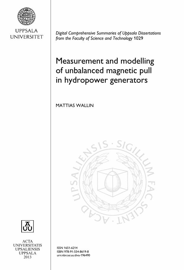
On the experimental generator it is possible to choose between one, two and
three damper bars and to select whether or not to connect the damper bars on
adjacent poles. The damper bar positions in the pole shoe on the experimental
generator can be seen in figure 5.3.
18
1.0τs 1.2τs
Bar 1 Bar 2 Bar 3
Rotation
Figure 5.3. The position of the damper bars seen from above.
5.3 Field winding interturn short circuit
In article IV the UMP was caused not by rotor eccentricity but by a short
circuit between one or more field winding turns on one of the poles. Ageing
and mechanical wear of the field winding insulation can result in electrical
contact between field winding turns. The result is a rotating unbalance which
can excite vibrations in the generator.
Configurations
Various degrees of field winding interturn short circuits were measured. The
flux Φ in a magnetic circuit is
Φ =NI
R(5.5)
where N is the number of turns in the coil, I the current in the coil and R is
the reluctance of the magnetic circuit.
In the FEM simulations the reduction in Φ was accomplished through a
reduction of N in the field winding for one pole, while on the experimental
generator, some of current, I, was shunted past one pole through a resistorparallel with the pole field winding. The configurations are REF, 4.3, 9.5,
17 and 30 where REF is the unmodified rotor and the numbers refer to the
reduction in ampere turns in percent on pole eleven.
Unbalanced magnetic pull from field winding short circuit
The effect on the air gap flux is described in chapter 7 and in article IV. A UMP
which rotates with the mechanical frequency caused by the reduced flux from
the affected pole is detected. Another observation is that the unaffected poles
with the same polarity as the damaged pole experience an increase in flux
density. The effect is seen in the measurements, the finite element calculations
and in the simple magnetic circuit representation of the generator depicted in
figure 2.2.
19

5.4 Standstill frequency response test
In article V a standstill frequency response, SSFR, test on the experimentalgenerator is performed to identify the machine transfer functions. Unlike the
standard SSFR test, which is described in [10], the study presented in article
V includes measurements of damper winding currents and voltages. This re-
quired a redefinition of the damper equivalent circuit from the form represent-
ing the physical damper winding to a dq representation. The new equivalent
winding is described in section II of article V.
Configurations
In the test a voltage with varying frequency is applied to two of the stator
phases while the third is left open. The result is a magnetic flux in the air gap
which fluctuates in amplitude but does not rotate. The test is performed with
the rotor in the direct, d, and the quadrature, q, axis positions.
The test was performed with the applied voltage varying in frequency from
5mHz to 300Hz. Complete and partial damper winding configurations were
used as well as a rotor without any damper winding.
It is stressed in [10] that the stator winding must keep a constant temperat-
ure so the test is performed at current levels which are only a fraction of the
rated levels. Hence the obtained parameters do not include effects of magnetic
saturation.
20

6. Experimental generator
All articles included in this thesis contain measurements from the experi-
mental generator Svante at the Division of electricity at Uppsala university.
The construction of the generator represent a substantial part of the work be-
hind this dissertation. Article I describes the construction of the generator.
This chapter contains some additional information and includes work done
after the publication of the article.
6.1 Construction
The construction process started with the donation of a twelve pole three phase
vertical axis synchronous motor to the division.
Original motor
Other characteristics of the machine was that it had salient poles with solid
pole shoes and that the rating was 185kW at 380V and a cosϕ of 0.9. As an
experimental machine the motor was not very suitable in its original configur-
ation since very few components were accessible for measurements and there
were no adjustment capabilities to modify parameters of interest. On the otherhand, the machine was in good condition and perfect as a base for a test setup.
A few modifications were made to the rotor and the stator of the motor to
turn it into a generator more similar to hydropower production machines and
to allow for the reconfigurations needed for various experiments. The rotor
and the stator were also individually suspended to allow for measurement of
the magnetic pull in the air gap.
Rotor
To reduce the risk of the rotor coming into contact with the stator during non-
centered operation the average air gap was increased through a reduction of the
pole body height. Given that there had to be room also during non-centered
operation for the air gap flux density sensors a longer air gap allowed for a
larger relative eccentricity. It was also easier to implement certain relative ec-
centricity on a larger air gap. Finally, a larger relative eccentricity increased
the signal to noise ratio in some of the experiments that were planned.
21

Laminated pole shoes
Laminated poles and rotor rings are standard on large hydropower generators
[11]. On the experimental generator the original cast rotor was kept but, as
the pole bodies were shortened more than was required for the increased air
gap length, laminated pole shoes could be mounted. The laminated pole shoes
serve to reduce the eddy currents in the pole face resulting from variations in
the air gap flux density. Under most circumstances the rotor poles are subject
to a smaller variation in the flux density than the stator, which sees a complete
reversal of the magnetic field every electric cycle, and therefore the lamination
thickness is often thicker in the rotor than in the stator. The pole shoes of the
experimental generator were made of 2mm varnished sheet steel compared
to the 0.5mm original steel of the stator. Figure 6.1 shows the shape of the
laminated pole shoe and figure 4 in article I shows the geometry of the poleshoe mounted on the pole body.
1.0τs 1.2τs
Rotor fluxsensor 1
Rotor fluxsensor 2
Rotation
Figure 6.1. Two air gap flux sensors was mounted on one of the poles. The signals
was transmitted to a stationary computer through the wireless module shown in figure
6.9.
Damper winding
One of the main experiments the generator was built for was to investigate the
effect of a damper winding on the reduction UMP. The rotor was therefore
equipped with a removable and reconfigurable damper winding. A cross sec-
tion of a pole body with the pole shoe and the damper bar slots is shown in
figure 6.1. The damper bar slots were not distanced evenly but rather with theseparation of 1 and 1.2 stator slot pitches. This was done so that the effect of
damper bar pitch on stator voltage total harmonic distortion, THD, could be
investigated.
An example of a damper winding configuration is shown in figure 6.2. Here
two damper bars, out of three possible, and the inter-pole connectors are used.
The damper bars and the inter-pole connectors are all attached to a copper bar
at each end of the pole. The damper bars are insulated from the pole plates by
22

Air gap
Field winding
Coil
Empty
damper slot
Damper barsInter-pole
connector
Rotation
Figure 6.2. Inter pole connectors as well as individual damper rods can be removed.
In the figure two out of three possible damper bars are mounted leaving one position
empty.
Pole
Rotation
ZCiC1iD1
−
+
U1
ZD
ZC ZA
ZA iD3
−
+
U3
ZD
ZC
ZC iC2
Figure 6.3. Circuit diagram of a section of a complete damper winding with two
damper bars per pole seen from the rotor shaft. The interpole connectors are repres-
ented by the impedances ZC . The direction of rotation is anticlockwise
heat shrinkable sleeves. Figure 6.3 contains the circuit diagram for a complete
damper winding with two damper bars.
Stator
The stator could be used as it was with the exception of a division of the
double layer concentric winding into two circuits to enable the parallel circuit
experiment described in article II .
Stator suspension
Adjustable rotor eccentricity and measurement of UMP required independent
suspension of the rotor and the stator. Either the rotor or the stator had to be
suspended in a way that allowed measurement of the radial forces. A motor
and gear box had to be connected to the rotor so it would have been difficult
to suspend that part of the generator. It was decided that the vertical axis con-
23

figuration of the machine would be kept and that stator should be suspended
in steel rods with ball joints at the ends.
Fx1
Fx2
Fy1 Fy2
Fr
Ft Fecc
R
ε
y
x
Figure 6.4. The radial support of the stator seen from above.
One benefit of this solution was that keeping the axis vertical made it pos-
sible to reuse the old bearings, which were in good condition. Other items
that were used directly from the motor were the slip rings and the brushes. A
new attachment for the brushes’ spring mechanism was however built. New
housings for the bearings also had to be made.
The geometry of the stator suspension is shown in figure 6.4. From the
measured forces it is also possible to calculate the mechanical torque on the
generator.
Parallel circuits
The physical separation of the stator winding into two halves was performed
by cutting the connectors between the coils instead of cutting the coils them-
selves. With this solution the connectors required to alternate between one-and two-circuit operation was greatly reduced. The two possible stator wind-
ing configurations are shown in figure 5.2.
Svante
Figure 6.5 shows a drawing of the resulting machine with a few of the com-
ponents labelled. Worth noting is that the rotor is fixed and that the stator is
suspended in such a way that it can be moved horizontally. All components
seen in figure 6.5, except for the motor and gearbox, were designed from the
24

geometry of the donated motor and the desired capabilities of the experimental
generator. Some of the data for the resulting machine are listed in table 6.1.
Longitudinalsupport bar
Thrust/journalbearingBrushholder
Radialsupport bar
Journalbearing
Inductionmotor Gear
3.5
m
Figure 6.5. A structure was built to independently suspend the rotor and the stator.
The figure shows how the rotor rests on a thrust bearing and stator is suspended in
metal bars. One horizontal beam in front of the stator has been removed from the
drawing for clarity.
Drive, motor and gear box
A 75kW induction motor and an inverter were used to power the generator.
The motor had four poles whereas the generator had twelve and a 3:1 gearbox
was installed between the motor and the stator to give a suitable working speed
for the induction motor and its inverter during synchronous operation of the
generator.
Magnetisation equipment
The field current can be supplied either a by purpose built rectifier or from a
controlled laboratory supply. The former was used in articles I and II .
25

Table 6.1. Main parameters for the refitted test generator.
Frequency 50Hz
Number of pole pairs 6
Speed 500rpm
Slots per pole and phase 3
Number of stator slots 108
Coil pitch 9
Stator inner diameter 725mm
Stator length 303mm
Air gap length 8.4mm
Power of driving motor 75kW
Rotor weight 900kg
Stator weight 700kg
Synchronisation equipment
Synchronised operation is the usual mode of operation for hydropower gener-
ators and synchronisation equipment has been installed on the test setup to cre-
ate realistic load conditions. Grid connected operation also enables research
into generator-grid interaction.A resistive load has also been installed to free the generator from constraints
on for example voltage and rotational velocity during operation under load.
The symbols in figure 6.6 are explained in table 6.2
EX
C
INV
U, f
IM
SG
R
Synchrono-scope
400V
11kV
Tm, Ω
156/400V
T1
T2
Figure 6.6. A schematic of the experimental generator, its drive and the connection to
the grid. The symbols are explained in table 6.2.
26

Table 6.2. Symbols used in figure 6.6.
EXC Field winding exciter
f Grid and generator frequency comparison
IM Induction motor
INV Inverter
R Resistive load
SG Synchronous generator
T1 156V to 400V transformer
T2 400V to 11kV transformer
Tm Mechanical torque
U Grid and generator voltage comparison
Ω mechanical frequency
6.2 Measurements
The experimental generator was built to study electromagnetic phenomena
as well as to validate the finite element software described in chapter 4. To
achieve this several types of sensors were mounted on both the stationary and
the rotating parts of the generator.
All measurements presented in articles I–IV were collected as voltage sig-
nals and stored at a rate of 10 000 samples per second. In total 28 signals were
used. Apart from an amplification of the strain gauge signals no filtering or
other form of signal manipulation was performed on these signals.
Measurements were taken with differential channels and sensors were, whereverpossible, kept floating. Twisted pair signal cables were used.
In article V additional temporary measurement points were used. In the art-
icle the amplification of the signals from the induced damper and field winding
voltages and currents and the data collection frequency were selected depend-
ing on the frequency of the applied voltage.
Non-rotating measurements
Not all measurements below were available in every experiment, there was for
example no damper voltage signal available during damper current measure-
ments, but all available measurements were recorded.
Stator air gap flux
Hall sensors were attached to two stator teeth 90 mechanical degrees apart.
The sensors were powered with a constant current of 1mA. The angular sep-
aration of the sensors would cause them detect different levels of flux density
during non-centered operation. Hall sensors were selected instead of search
coils because of their ability to measure a constant flux level and because of
their higher resolution [12].
27
Stator voltages
The parallel circuit voltages could be measured separately during no load op-
eration with two stator circuits. Each phase was monitored and in total six
channels were dedicated for stator voltage measurements.
Stator currents
Three Hall effect current transducers were mounted to measure intrastator cur-
rents in each phase during parallel circuit operation. Another three transducers
were measuring the current from the generator during operation with load.
Stator forces
Strain gauges were used to measure the forces on the stator. They were posi-
tioned so that amplitude and direction of the UMP as well as the torque on the
generator could be calculated from the recorded data. Figure 6.4 contains a
schematic of the geometry. Four strain gauges were mounted in a full Wheat-
stone bridge on each of the four rods. The signals for the four bridges were
then amplified individually before being stored together with the other meas-
urement data. The linearity of the strain gauges and the gain of the amplifiers
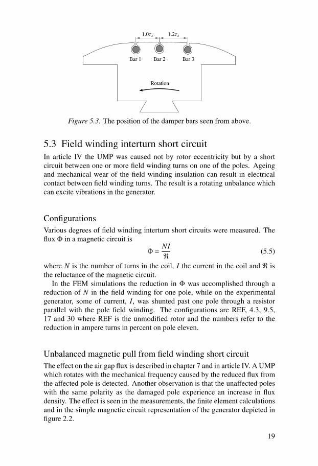
have been calibrated with known weights. Figure 6.7 contains a photograph
of one of the four rods used to fixate the stator radially. The positions of therods on the stator can be seen in figure 6.4.
Figure 6.7. The stator was secured radially with four 16mm metal rods. Figure 6.4
shows the position of the rods. Each rod was equipped with four strain gauges in a
wheatstone bridge.
Rotating measurement equipment
Measurements collected on the rotor were transferred via wireless LAN to the
measuring computer.
Rotor air gap flux
Two Hall sensors, of the same type as used on the stator, were mounted on one
of the poles. At eccentric operation these sensors detect a varying flux density
over one mechanical revolution. They also detect the stator slot ripple in the
air gap flux density. The position of the rotor flux sensors are shown in figure
6.1.
28

Damper winding voltage
With the damper winding replaced with open circuit conductors the voltage
induced in the damper bars was measured.
Damper winding currents
On one pole current Hall sensors were placed around the damper bars and
interpole connectors. There were three sensors for the damper bars and two for
the interpole connectors. Figure 6.8 is a photograph of the housing in which
the currents sensors were mounted. The positions of the sensors coincide with
the current arrows in figure 6.3. ZC in the figure represent the removable
interpole connectors.
Figure 6.8. On one of the poles the damper bar and connector currents were measured
with Hall effect current transducers placed on the lower side of the rotor. A sensor is
mounted around each damper bar above the flat copper piece. The interpole connect-
ors, the two black cables, pass through two more current sensors.
Wireless data transfer
The data collected on the rotor was transferred through a WLAN connection to
the stationary measurement computer. To minimise the g-forces on the trans-
mitter and have a free line of sight from the aerial to the stationary computer it
was mounted directly on the top end of the rotor axle, as shown in figure 6.9.
29
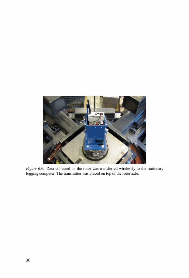
Figure 6.9. Data collected on the rotor was transferred wirelessly to the stationary
logging computer. The transmitter was placed on top of the rotor axle.
30

7. Results
The results from the four research areas presented in chapter 5 can be found
in their respective articles II–V. This chapter contains the most interesting
findings from articles II–IV and some additional material not included in the
articles.
7.1 Magnetic saturation
Hydropower generators are normally operated at some degree of magnetic
saturation but to avoid nonlinear effects from saturation on the measurements
all experiments were carried out at unsaturated levels of magnetic flux density.
One way of finding the magnetisation where the iron is starting to saturate is
to plot the no-load voltage curve and see at which field current the relationship
between the terminal voltage and the field current ceases to be linear. Figure
7.1 contains the line to line voltage of the experimental generator as a function
of the field current. To within measurement accuracy there was no detectable
saturation at field currents below 15A and all experiments were performed at
a field current of 15A or lower. The correct voltage for synchronisation with
the grid, through the transformer shown in figure 6.6 was obtained at a field
current of 13A.The no-load voltage curve was also used to get the correct shape for the
BH curve used in the simulations. Due to the unknown materials of the ro-
tor and the stator the terminal voltage and flux density of the simulations did
not initially agree with the measurements but from the measured BH curve
it was possible to obtain simulated values which corresponded well with the
measurements.
7.2 Parallel circuits and rotor eccentricity
Section 5.1 described the parallel circuit configuration of the experimental
generator. It was also mentioned that in addition to FE simulations an analyt-
ical permeance model was used to study the effect of parallel stator circuits.
This study was performed before the air gap flux density sensors had been
mounted on the experimental generator. The shortest air gap is positioned at
180 degrees in the plots. For a more detailed presentation of the parallel circuit
study please see article II.
31

0 10 20 30 40 500
50
100
150
200
250
300
350
400
450
Field current [A]
Ter
min
al v
olta
ge [
V]
Figure 7.1. The no-load voltage. All experiments were carried out at a field current of
15A or lower to avoid effects of magnetic saturation.
Effect on unbalanced magnetic pull
With the rotor displaced parallel to the symmetry line of separation of the two
circuits, the x axis in figure 5.1, the effects on UMP and terminal voltage were
negligible but when the stator was displaced perpendicular to the symmetry
line, the y axis in figure 5.1, a large reduction of the UMP could be observed.
The results are summarised in table 7.1. The effect of eddy currents are not
included in either of the computer models so the UMP at standstill is the same
as for the configuration with one circuit.
Table 7.1. UMP reduction from parallel circuits with the eccentricity perpendicular
to the symmetry line.
Configuration Measured FEM Permeance model
Standstill Fy [N] 4250 - -
One circuit Fy [N] 3216 4115 4072
Two circuits Fy [N] 1345 1734 1774
Reduction relative to one circuit Fy [%] 58 58 56
Parallel circuit voltages
Figure 7.2 contains the voltages of the two parallel circuits when the rotor
is displaced parallel to the y axis. Due to the difference in the average flux
density for the two circuits the induced circuit voltages are not equal. In the
32

figure circuit one, with the on average shorter air gap, is represented by solid
lines for phases a, b and c. The average rms voltage difference between the two
circuits is 19 percent. The simplified circuit voltages of equations (5.2) and
(5.3) predicted a difference of 31 percent. Two explanations of the discrepancy
are the linearisation of the equations and an error in the measurement of the
relative eccentricity used in the equations.
0 50 100 150 200 250 300 350−100
−50
0
50
100
Position (degrees)
UP
H [
V]
Ua,1
Ub,1
Uc,1
Ua,2
Ub,2
Uc,2
Figure 7.2. The open circuit voltages measured at a relative eccentricity of 0.24 and
a field current of 15A for the two stator circuits. Circuit one, represented by the solid
lines, had an, on average, smaller air gap and hence larger total flux than circuit two.
The result is a difference in the induced voltages in the two circuits. The layout of the
circuits are shown in figure 5.1.
Parallel circuit currents
The induced voltage difference between the two halves of the stator windingwill, if the two winding sections are connected in parallel, drive intrastator
currents. The measured currents from such an experiment are shown in figure
7.3. An effect of these currents is a reduction in the air gap flux density differ-
ence between the two halves of the stator. It is this reduction in flux density
difference which causes the reduction of the UMP shown in table 7.1.
During the experiment the generator was operated at no-load and, besides
reducing the UMP, these currents only result in resistive losses.
33

0 50 100 150 200 250 300 350
−60
−40
−20
0
20
40
60
Position (degrees)
I [A
]
Ia
Ib
Ic
Figure 7.3. The parallel circuit currents driven by the difference in induced voltage
between the two stator halves shown in figure 7.2. Measurements were taken at no-
load.
7.3 Damper windings and rotor eccentricity
Article III describes the effect of different damper winding configurations on
UMP during rotor eccentricity. A description of the damper winding config-
urations and the terminology used here can be found in section 5.2. Below
follows a brief summary of the findings from the article. The shortest air gap
is positioned at 180 degrees in the plots.
Effect on unbalanced magnetic pull
The resistance of the damper windings and the fraction of the pole face area
covered by the damper winding were, through simulations, found to have a
large influence on the reduction of the UMP from the damper winding. With
the damper winding currents from the experimental generator the effect on the
UMP was negligible. All experiments and simulations were carried out at field
current of 15A and a relative eccentricity of 0.44.
Table 7.2 contains the simulated forces resulting from the four configura-tions described in section 5.2. In these simulations of the experimental gen-
erator the damper winding resistances were set to result in the same damper
winding currents as in the measurements.
As a comparison a 28 pole generator used in hydropower production, with
a damper winding covering a large fraction of the pole face, was studied in
simulations. The damper winding resistances were set to values calculated
from material resistivity only and no contact resistances were included, much
34

as would be the case for a generator with a soldered damper winding. The
resulting large reduction in UMP can be seen in table 7.3. In the table it is also
possible to see that a relatively large tangential force component, approxim-
ately a quarter of the total remaining UMP, is introduced by the damper wind-
ing. In neither the experimental nor the production generator does the presence
of damper winding interpole connectors have a large influence on the UMP.
The level of interpole connector currents in the experimental generator can be
found in article III. In the production generator they were approximately an
order of magnitude less than the damper bar currents.
Table 7.2. Simulated UMP change on the experimental generator for the studied
damper winding configurations. The last column is the change in UMP compared to
the configuration WD. The notation WD, NC and C are described in section 5.2.
Configuration Fx [N] Fy [N] Fecc [N] ΔFecc [%]
WD 9174 -1 9174 -
D2-C 9192 35 9192 0.2
D13-NC 9156 139 9157 -0.2
D13C 9150 188 9152 -0.2
Table 7.3. Simulated UMP change on a 28 pole production generator for the studied
damper winding configurations. The last column is the change in UMP compared to
the configuration WD. D1-7 indicates that all seven damper bars per pole were used.
Configuration Fx [N] Fy [N] Fecc [N] ΔFecc [%]
WD 325800 300 325800 -
D1-7-NC 184600 49250 190670 -41.5
D1-7-C 184200 49000 190220 -41.6
7.4 Field winding interturn short circuit
Unbalanced magnetic pull caused by field winding interturn short circuit, de-
scribed in section 5.3 was studied in article IV. The experiments were per-
formed with a centered rotor at a field current of 15A. In the figures the index
REF indicates the magnetically symmetric rotor and the numbers the degree
of interturn short circuit on pole eleven.
Resulting unbalanced magnetic pull
A winding interturn short circuit on one of the poles results in a reduced flux
density for the pole. Figure 7.4 contains the absolute air gap flux densities
35
0 50 100 150 200 250 300 3500
0.05
0.1
0.15
0.2
0.25
0.3
0.35
0.4
Position [deg]
Air
gap
flu
x de
nsity
[T
]
BREF
B9.5%
B30%
6 7 8 9 10 11 12 1 2 3 4 5
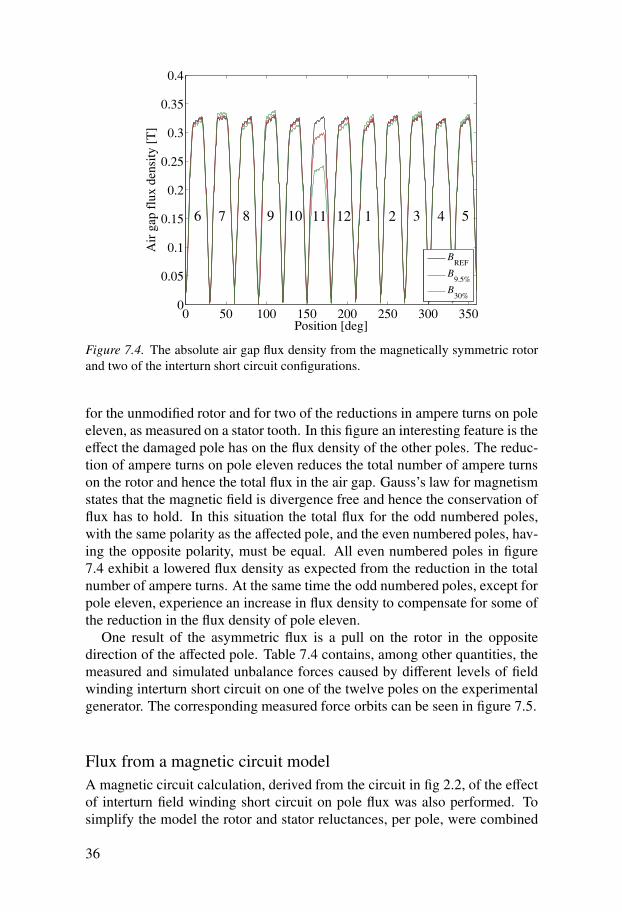
Figure 7.4. The absolute air gap flux density from the magnetically symmetric rotor
and two of the interturn short circuit configurations.
for the unmodified rotor and for two of the reductions in ampere turns on pole
eleven, as measured on a stator tooth. In this figure an interesting feature is the
effect the damaged pole has on the flux density of the other poles. The reduc-
tion of ampere turns on pole eleven reduces the total number of ampere turns
on the rotor and hence the total flux in the air gap. Gauss’s law for magnetism
states that the magnetic field is divergence free and hence the conservation of
flux has to hold. In this situation the total flux for the odd numbered poles,
with the same polarity as the affected pole, and the even numbered poles, hav-
ing the opposite polarity, must be equal. All even numbered poles in figure
7.4 exhibit a lowered flux density as expected from the reduction in the total
number of ampere turns. At the same time the odd numbered poles, except for
pole eleven, experience an increase in flux density to compensate for some of
the reduction in the flux density of pole eleven.
One result of the asymmetric flux is a pull on the rotor in the oppositedirection of the affected pole. Table 7.4 contains, among other quantities, the
measured and simulated unbalance forces caused by different levels of field
winding interturn short circuit on one of the twelve poles on the experimental
generator. The corresponding measured force orbits can be seen in figure 7.5.
Flux from a magnetic circuit model
A magnetic circuit calculation, derived from the circuit in fig 2.2, of the effect
of interturn field winding short circuit on pole flux was also performed. To
simplify the model the rotor and stator reluctances, per pole, were combined
36

Table 7.4. Summary of the changes in ampere turns, flux for pole eleven, UMP and
terminal voltage relative to the magnetically symmetric rotor. Measured/simulated
results.
Configuration ΔAt[%] ΔΦPOLE11 [%] FUMP [N] ΔU [%]
4.3 4.28 4.4/3.6 118/101 0.51/0.33
9.5 9.50 8.6/7.3 234/223 0.74/0.73
17 17.4 15.0/14.2 378/401 1.4/1.4
30 29.6 25.5/23.9 612/659 2.4/2.4
−1000 −500 0 500 1000−1000
−500
0
500
1000
FX [N]
FY [
N]
w
FREF
F4.3%
F9.5%
F17%
F30%
Figure 7.5. The measured force orbits from various degrees of field winding interturn
short circuit on pole eleven. The black small orbit in the middle comes from mechan-
ical and magnetic unbalances in the rotor of the experimental generator. Its maximum
amplitude is approximately 70N.
into a single reluctance. The resulting fluxes, shown in figure 7.6 exhibit thesame pattern as described above for the flux density measurements. Article IV
describes the magnetic circuit in more detail.
7.5 Results not included in the articles
Damper winding circuit parameters
Damper winding resistance and inductance for the configuration with two
damper bars and no interpole connector, D13-NC, were determined from the
measured damper winding voltage and current.
The stator slot ripple in the measurements was quite pronounced as can be
seen in figures 7.7 and 7.8. To avoid the problem of slot ripple the data for both
37

6 7 8 9 10 11 12 1 2 3 4 5
5
10
15
Pole
Air
gap
flu
x fo
r 17
% [
mW
b]
Magnetically
symmetric rotor
Figure 7.6. The pole flux from the configuration with 17% interturn short circuit on
pole eleven calculated the magnetic circuit. The red line represents the pole flux for
the rotor without any parallel resistor on pole eleven.
voltage and current was fitted to the function shown in equation 5.4 before the
circuit parameters were estimated. The fitted data was then used to find RD
and LD in
UD = RDID +LDdID
dt. (7.1)
where UD and ID are the fitted voltage and current. The damper winding resist-
ance, RD, was found to be 2.3mΩ. As a comparison, the resistance calculated
from material resistivity only was 0.4mΩ. Contact resistances between the
damper bars and the interbar connectors are believed to be the main cause
of the difference between the experimental and theoretical values. Regarding
the inductance, LD, some caution should be used in the interpretation of the
obtained value of 4μH. With a measured phase shift between voltage and cur-
rent of 5.5 degrees, shown in figure 7.9, there is some room for measurement
error and at small angles the relationship between measured angle and the in-
ductance is approximately linear. A fit of the measured data, where the slotripple is prominent, to equation 7.1 results in the same RD and an inductance
of 3.2μH. The latter value for LD is most likely closer to the true value due to
the larger effect of the inductance at the slot frequencies.
The impact of the inductance is quite small at the mechanical frequency,
8.3Hz, but at the slot ripple frequency of 900Hz the effect is large as can be
seen from the difference in the relative slot ripple amplitude in the voltage in
figure 7.7 and the current in figure 7.8.
38

0 50 100 150 200 250 300 350
−0.1
−0.05
0
0.05
0.1
0.15
Position [deg]
Dam
per
volta
ge [
V]
Measured UD13
Fitted UD13
Figure 7.7. The measured and fitted damper voltage for the configuration with two
damper bars and no interpole connectors. The stator slot ripple in the damper voltage
is more prominent in the part of the revolution where the air gap is small.
0 50 100 150 200 250 300 350−50
0
50
Position [deg]
Dam
per
curr
ent [
A]
Measured ID13
Fitted ID13
Figure 7.8. The measured and fitted damper current for the configuration with two
damper bars and no interpole connectors.
Flux density and damper voltage measurement verification
As a verification of the measurement equipment the expected induced damper
voltage calculated from the measured variation in air gap flux density was
compared to the actual damper voltage. To avoid the noise of the stator slot
39

0 50 100 150 200 250 300 350
−0.1
−0.05
0
0.05
0.1
Dam
per
volta
ge [
V]
Position [deg]
−40
−20
0
20
40
Dam
per
curr
ent [
A]
Fitted UD13
Fitted ID13
Figure 7.9. The fitted damper voltage and current for the configuration with two
damper bars and no interpole connectors. Note the different scales on the two y axes.
ripple the flux density was fitted to equation (3.11) before the expected inducedvoltage was calculated. Figure 7.10 contains the graphs of the measured and
fitted rotor flux density. One thing worth noticing in the figure is how pro-
nounced the stator slot ripple is near where the air gap is at its shortest, at 180
degrees, compared to on the opposite side of the generator. From the rotor flux
the damper voltage the calculated as according to equation (5.4). The result-
ing calculated damper voltage together with its measured value can be seen in
figure 7.11.
40

0 50 100 150 200 250 300 3500
0.1
0.2
0.3
0.4
0.5
Position [deg]
Rot
or f
lux
dens
ity [
T]
Measured BR1
Fitted BR1
Figure 7.10. Sensor one shown in 6.1 was used to measure the air gap flux density in
front of one of the poles. Here both the measured flux density, containing significant
slot ripple in the small air gap, and its fitted value can be seen.
0 50 100 150 200 250 300 350
−0.1
−0.05
0
0.05
0.1
0.15
Position [deg]
Dam
per
volta
ge [
V]
Fitted UD13
From flux, UD13
Figure 7.11. The damper voltage calculated from the variation in flux density in the
air gap.
41


8. Summary of articles
In this chapter short summaries of the contents of the articles included in the
dissertation are presented. The authors contribution to each article is also spe-
cified.
Article I
Design and construction of a synchronous generator test setup
This paper contains a description of the functionality of the test generator
setup. Characteristics of the generator as well as the installed measurement
equipment are discussed. An initial test of the effect of damper winding con-
figuration on voltage harmonics is included.
The paper was presented by the author, who is the main author of the paper,
at The XIX International Conference on Electrical Machines in Rome, Italy,
2010. It was also selected for inclusion in the IEEE Xplore database.
Article II
Reduction of unbalanced magnetic pull in synchronous machines due to
parallel circuits
The first experiment on the test generator concerning rotor eccentricity is
described in this article. Measurements of the UMP and currents in the paral-
lel circuits have been performed under static eccentricity with the stator wind-
ing connected as one circuit or two parallel circuits. Experiments were done
at noload conditions. Two numerical studies of the force reduction are also
presented, one using a finite element code and one using a permeance model.
The reduction of UMP was strongly dependent on the direction of unbalancerelative to the line of separation of the stator circuits. Eddy currents induced in
the rotor during operation were found to reduce the standstill UMP with more
than 20 percent.
The author performed the measurements and the finite element simulations
presented and he is the main author of the article.
The article was published in IEEE Transactions on Magnetics, vol. 47(12),
pp 4827-4833, December 2011
43

Article III
Damper winding influence on unbalanced magnetic pull in hydropower
generators with rotor eccentricity
Continuous and noncontinuous damper windings resulted in different damper
winding currents but their effect on the UMP was found to be very similar.
Measurements of the UMP, damper bar currents and air gap flux density were
performed on the experimental generator configured with static eccentricity
under no-load conditions. Finite element simulations of the different configur-
ations detailing the damper winding induced flux changes are also presented.
The author performed the measurements and simulations presented and he
is the main author of the article.
The article was submitted to IEEE Transactions on Magnetics, November
2012
Article IV
Dynamic unbalanced pull from field winding turn short circuits in hydro-
power generators
The UMP resulting from field winding interturn short circuits is invest-
igated both experimentally and through numerical modelling. Flux density
measurements are performed on the experimental generator as well as on a 28
pole production generator. The occurrence of parallel stator branches com-
bined with a field winding short circuit gives rise to circulating stator currents
which are analysed. A field winding short circuit in one pole gives rise to an
increase in the flux in the other poles with the same polarity. This effect is
explained.
The author performed the measurements and simulations presented and he
is the main author of the article.
The article was submitted to Electric Power Components and Systems, Feb-
ruary 2013
Article V
Standstill frequency response test on a synchronous machine extended
with damper bar measurements
Standstill frequency response (SSFR) test data including damper winding
measurements for three physically different damper winding configurations is
presented. A method to incorporate measured damper bar voltages and cur-
rents in the SSFR analysis scheme is proposed. The validity of the generator
models identified through the test is substantiated by comparison of the simu-
lated and measured machine response to a drive torque step disturbance.
44
The author contributed to the measurements performed for the study and
the development of the equivalent damper circuit.
Manuscript
45


9. Svensk sammanfatting
1878 kallade Aristide Bergès vattenkraften för det vita kolet, fr. la houille
blanche, för att visa på den mängd kraft som fanns lätt tillgänglig i snön och
isen i de franska alperna.
Vattenkraftutvinning i industriell skala i Sverige tog sin början 1910 i ochmed drifttagningen av de fyra första generatorerna i Olidans kraftverk i Göta
Älv. Det första större vattenkraftverket i norra Sverige, Porjus, invigdes 1915.
Fram till att kärnkraft började tas i bruk för elproduktion i Sverige under
sjuttio- och åttiotalen stod vattenkraften för den överväldigande delen av den
elektricitet som producerades. Vattenkraften var och är en avgörande förutsätt-
ning för den svenska industrin och välfärden. I dag står vattenkraften för 45
procent, eller 65 TWh, av den elektricitet som används i Sverige.1
Även om tekniken är väl utvecklad så finns det ett behov av en ökad förstå-
else för elektromagnetiska fenomen i synkrongeneratorer för att undvika onö-
digt slitage, minskad livslängd och haverier. Osäkerhet i elförsörjningen såväl
som högre elektricitetspriser, saker som påverkar både industrin och hushål-
len, kan bli följden av driftproblem inom vattenkraften.
Vid sidan om de ekonomiska konsekvenserna så bör vattnet i våra redan
utbyggda älvar av miljöskäl utnyttjas på ett optimalt sätt i väl fungerande vat-tenkraftverk.
Asymmetriska magnetkrafter uppstår när rotorn i en generator inte är cen-
trerad i statorn eller när det magnetiska flödet i luftgapet av någon annan anled-
ning inte är symmetriskt. Dessa krafter kan förkorta livslängden på generator
eller orsaka haveri genom ökat slitage på lager och andra infästningskompo-
nenter för rotorn och statorn. Asymmetriskt luftgapsflöde kan också inducera
dämpstavsströmmar och cirkulerande strömmar i statorn vilket leder till re-
sistiva förluster och större värmeutveckling, vilket i sin tur medför ökade eko-
nomiska förluster och ett ökat termiskt åldrande hos maskinen.
Denna avhandling undersöker i tre studier olika konsekvenser av magnetisk
obalans hos synkrongeneratorer.
Arbetet avhandlingen grundas på har utförts vid Avdelningen för elektrici-
tetslära vid Uppsala universitet. Resultat har inhämtats från numerisk analys,
analytiska modeller och mätningar på den experimentutrustning som byggtsav författaren.
Forskningen som presenteras här är en del i ett Elektraprogram som he-
ter Utveckling av elektromagnetiska lastmodeller för simulering av interak-
tionen mellan rotor och stator i vattenkraftgeneratorer. Elektra finansieras av
1Elektricitet utgör en tredjedel av den energi som används i Sverige [1].
47

ABB, Trafikverket, Svenska Kraftnät och, genom Svensk energi, ett flertal
producent- och transmissionsföretag. Elektras syfte är att ”långsiktigt stärka
den svenska industrins konkurrenskraft och då i första hand elleverantörer,
kraftindustri och tillverkande industri.”
Avhandlingen inleds med en kort beskrivning av hur en synkrongenera-
tor fungerar och hur rotorexcentricitet ger upphov till obalanskrafter. Därefter
kommer i kapitel 4 en beskrivning av den finita elementmetod som använts i
datorsimuleringarna. Det följande kapitlet beskriver de fyra forskningsområ-
dena parallella kretsar och rotorexcentricitet, dämplinding och rotorexcentrici-tet, fältlindningskortslutning och karakterisering av synkronmaskiner genom
frekvensresponstester. Kapitel 6 är en genomgång av konstruktionsprocessen
av experimentgeneratorn samt den mätutrustning som installerats. Avhand-
lingen avslutas med en resultatdel.
48

10. Acknowledgements
I, the author, am indebted to Elektra and its member organisations for making
this research possible. Sven Jansson should be mentioned for being positive,interested and helpful in every aspect.
Construction of the test generator would not have been possible without the
very much appreciated help of Swedish Hydropower Centre, Svenskt vatten-
kraftcentrum, SVC, and Carl Tryggers stiftelse.
I want to thank Svante Leonsson at GE Hydro who donated the synchronous
motor without which the experimental generator could not have been built.
Additional help as well as good advice on construction matters was received
from Ove L. Andersson at SKF.
The meetings and discussions with the members of the Elektra and SVC
steering committee for research in hydropower generators have been a great
source of inspiration and advice to me. I am grateful to its members Jan-
Olov Aidanpää, Peter Altzar, Per-Olof Andersson, Mats Berg, Christer Bäck,
Niklas Dahlbäck, Håkan Hermansson, Anders Holm, Thommy Karlsson and
Mats Wahlén for showing interest in my work, all the discussions we have hadand, not to forget, the time they have spent travelling to our meetings.
I want to thank Mikael Jonsson together with the rest of the administrative
and technical staff at the Department of engineering sciences and the Division
of electricity. Without them there would have been no research to write about.
My assistant supervisor, Mats Leijon, should be mentioned for the good
atmosphere he has created at the Division of electricity and the group of skilled
and kind people he has gathered here.
I am very grateful to my supervisor Urban Lundin for his encourgement,
good comments on my writing and keen eye for interesting research topics.
In my daily work the discussions with my friend and colleague Johan Bladh
has been of great importance to both my research and to the atmosphere in the
office.
My former colleague Martin Ranlöf is worth a special mentioning for the
discussions we had, which I learnt a lot from, and for the work he did on theexperimental generator.
The rest of the hydropower group with Birger Marcusson, José Pérez-Loya,
Linn Saarinen and Per Sundqvist is a wonderful team which it has been great
fun to work in.
It has been a pleasure to work and teach with Mikael Bergkvist.
My dear friend Alexander has helped me to have a normal life away from
work.
49

I want to thank my parents and brother for being the best family anyone can
have and for putting up with me talking about my research.
Finally I want to thank Ann who decided to join my life as my time as a
PhD student was coming to an end and things started to get hectic. The time
with you has made everything easy. Thank you.
50

Bibliography
[1] Swedish Energy Agency. Energy in Sweden - facts and figures 2012, 2013.
[2] M. Ranlöf, R. Perers, and U. Lundin. On permeance modeling of large
hydrogenerators with application to voltage harmonics prediction. IEEE Trans.
Energy Convers., 25:1179–1186, 2010.
[3] J. H. Walker. Large Synchronous Machines - Design Manufacture, and
Operation. Clarendon press, Oxford, 1981.
[4] A. Nicolet, F. Delince, N. Bamps, A. Genon, and W. Legros. A coupling
between electric circuits and 2d magnetic field modeling. Magnetics, IEEE
Transactions on, 29(2):1697–1700, Mar 1993.
[5] G. Bedrosian. A new method for coupling finite element field solutions with
external circuits and kinematics. Magnetics, IEEE Transactions on,
29(2):1664–1668, Mar 1993.
[6] W.M. Arshad, H. Lendenmann, and H. Persson. End-winding inductances of
mva machines through fem computations and iec-specified measurements.
Industry Applications, IEEE Transactions on, 44(6):1693–1700, Nov.-dec.
[7] U. Lundin and A. Wolfbrandt. Method for modelling time-dependent
nonuniform rotor/stator configurations in electrical machines. Magnetics, IEEE
Transactions on, 45:2976–2980, 2009.
[8] Antero Arkkio. Analysis of induction motors based on the numerical solution of
the magnetic field and circuit equiations. PhD thesis, Helsinki University of
Technology, Laboratory of Electromechanics, Helsinki, Finland, 1987.
[9] S. Keller, M.T. Xuan, J.-J. Simond, and A. Schwery. Large low-speed
hydro-generators – unbalanced magnetic pulls and additional damper losses in
eccentricity conditions. Electric Power Applications, IET, 1(5):657–664, 2007.
[10] IEEE Std 115-2009. IEEE Guide: Test procedures for synchronous machines,
Part I - Acceptance and performance testing, Part II - Test procedures and
parameter determination for dynamic analysis, 2010.
[11] S Lagerkvist. Kompendium i konstruktiv elktromaskinlära, Del II
synkronmaski-nen. Chalmers, Göteborg, 1963.
[12] A. Elez, B. Tomicic, and A. Colak. The comparison of magnetic values
obtained from hall probes and measuring coils in synchronous generators. In
Electrical Machines, 2008. ICEM 2008. 18th International Conference on,
pages 1–4, sept. 2008.
51

Acta Universitatis UpsaliensisDigital Comprehensive Summaries of Uppsala Dissertationsfrom the Faculty of Science and Technology 1029
Editor: The Dean of the Faculty of Science and Technology
A doctoral dissertation from the Faculty of Science andTechnology, Uppsala University, is usually a summary of anumber of papers. A few copies of the complete dissertationare kept at major Swedish research libraries, while thesummary alone is distributed internationally throughthe series Digital Comprehensive Summaries of UppsalaDissertations from the Faculty of Science and Technology.
Distribution: publications.uu.seurn:nbn:se:uu:diva-196490
ACTAUNIVERSITATIS
UPSALIENSISUPPSALA
2013