Embed Size (px)
Citation preview
High-frequency, High-power Magnetic Component Design with Maxwell 3D
From Geometry Creation to Component Optimization
Dr. Jenna Pollock Tesla Motors
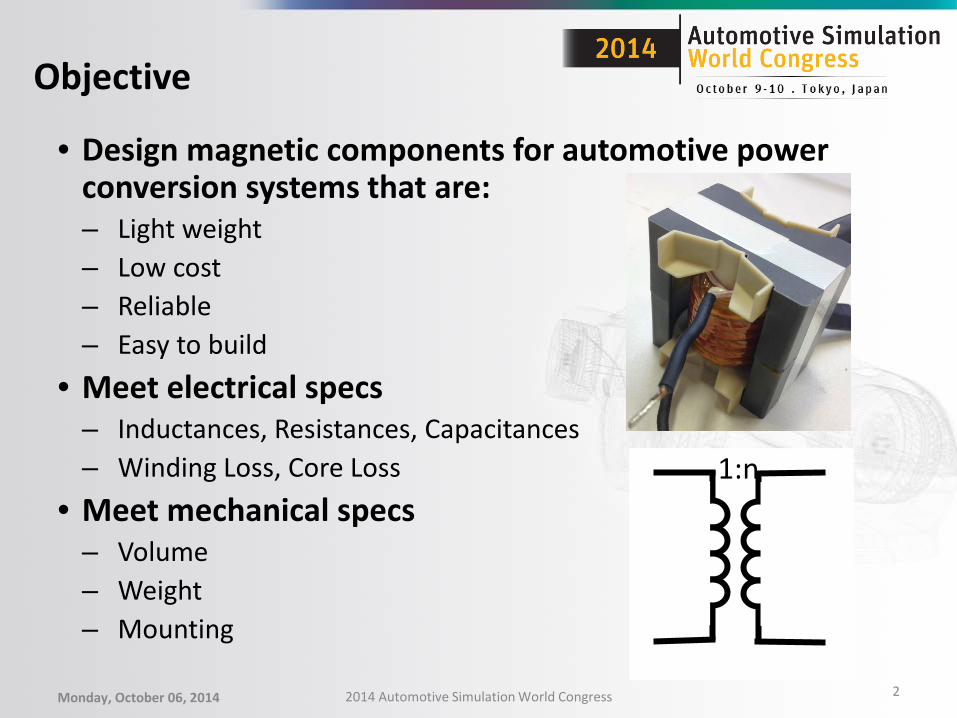
• Design magnetic components for automotive power conversion systems that are: – Light weight – Low cost – Reliable – Easy to build
• Meet electrical specs – Inductances, Resistances, Capacitances – Winding Loss, Core Loss
• Meet mechanical specs – Volume – Weight – Mounting
Objective
1:n
Monday, October 06, 2014 2014 Automotive Simulation World Congress 2
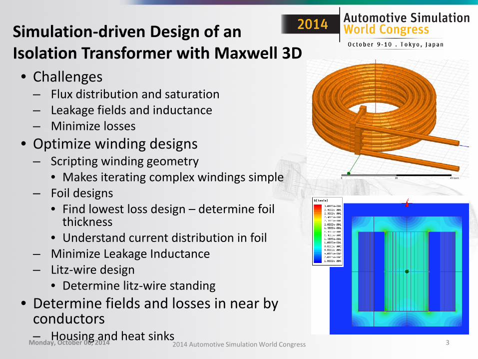
Simulation-driven Design of an Isolation Transformer with Maxwell 3D • Challenges
– Flux distribution and saturation – Leakage fields and inductance – Minimize losses
• Optimize winding designs – Scripting winding geometry
• Makes iterating complex windings simple – Foil designs
• Find lowest loss design – determine foil thickness
• Understand current distribution in foil – Minimize Leakage Inductance – Litz-wire design
• Determine litz-wire standing • Determine fields and losses in near by
conductors – Housing and heat sinks
Monday, October 06, 2014 2014 Automotive Simulation World Congress 3
1:n
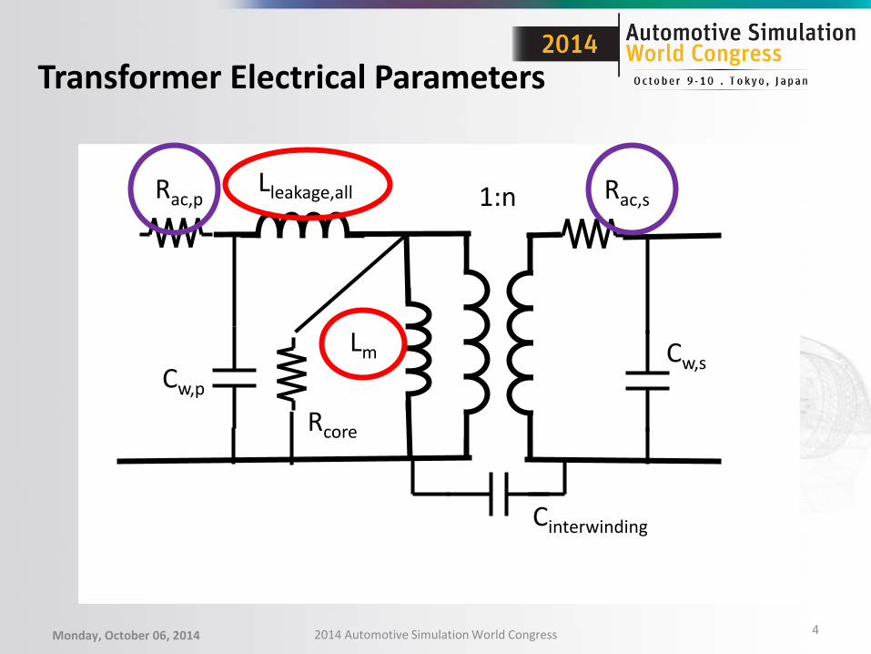
Transformer Electrical Parameters
Monday, October 06, 2014 2014 Automotive Simulation World Congress 4
Rac,p Rac,s Lleakage,all 1:n
Cw,p
Lm
Rcore
Cw,s
Cinterwinding

Transformer Design Example:
• Isolation transformer Parameter
Power level 3 kW Switching Frequency 120kHz Magnetizing inductance 1.3 mH Leakage inductance 4.2 uH Maximum power loss 1% Turns Ratio 8:1
Monday, October 06, 2014 2014 Automotive Simulation World Congress 5
Preliminary Transformer Design
• Trade off core and windings losses to find an optimal design for given electrical specifications – Use FEA to support analytical methods – FEA can fine tune design
• Specific electrical parameters • Specific size requirements
• A free transformer design resource: – http://ecee.colorado.edu/copec/book/slides/slidedir.html
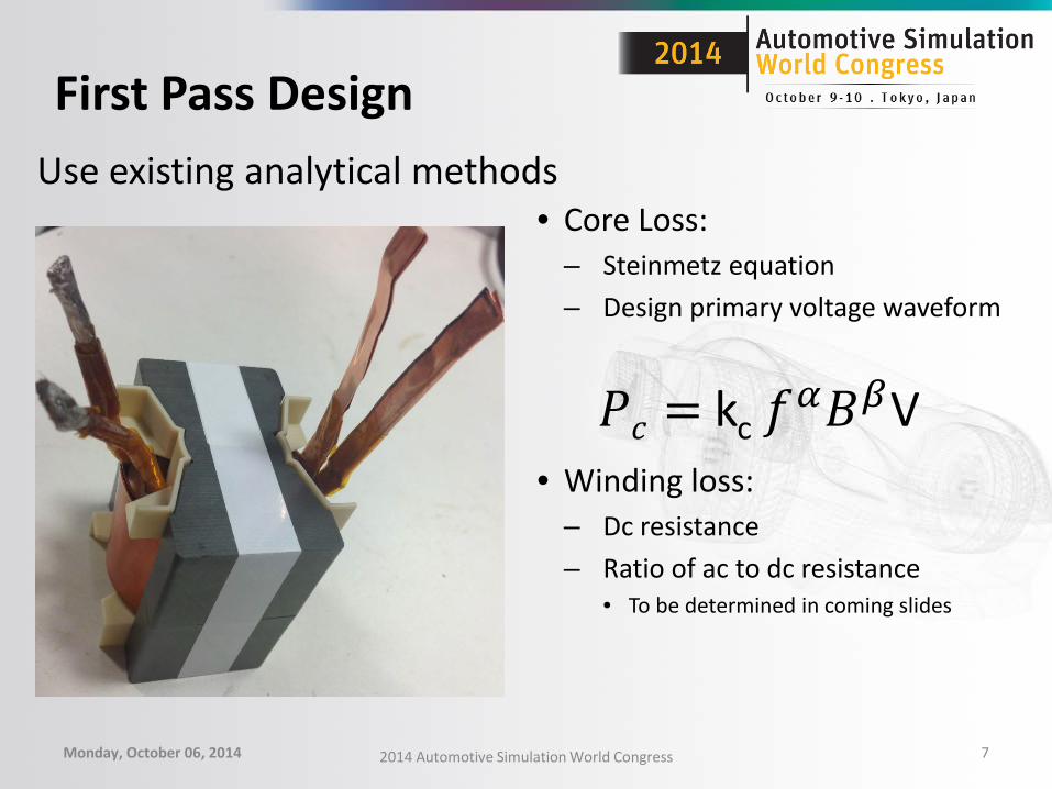
First Pass Design
Monday, October 06, 2014 2014 Automotive Simulation World Congress 7
• Core Loss: – Steinmetz equation – Design primary voltage waveform
• Winding loss: – Dc resistance – Ratio of ac to dc resistance
• To be determined in coming slides
Use existing analytical methods
𝑃𝑐 = kc 𝑓𝛼𝐵𝛽V
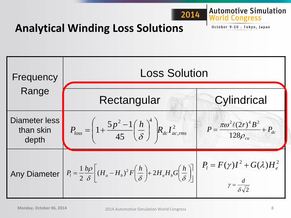
Analytical Winding Loss Solutions
Monday, October 06, 2014 2014 Automotive Simulation World Congress 8
Frequency Range
Loss Solution
Rectangular Cylindrical
Diameter less than skin
depth
Any Diameter
dccu
PBrP +=ρ
πω128
)2( 242
22 )()( el HGIFP λγ +=
+
−=
δδδρ hGHHhFHHbP babal 2)(
21 2
2,
42
45151 rmsacdcloss IRhpP
−
+=δ
2δγ d=
101
102
103
0
1
2
3
4
5
6
7
Frequency, kHz
Indu
ctan
ce, u
H
360/36100/38AWG 14
101
102
0
50
100
150
200
250
Frequency, kHz
Res
ista
nce,
moh
ms
360/36 wire100/38awg 14
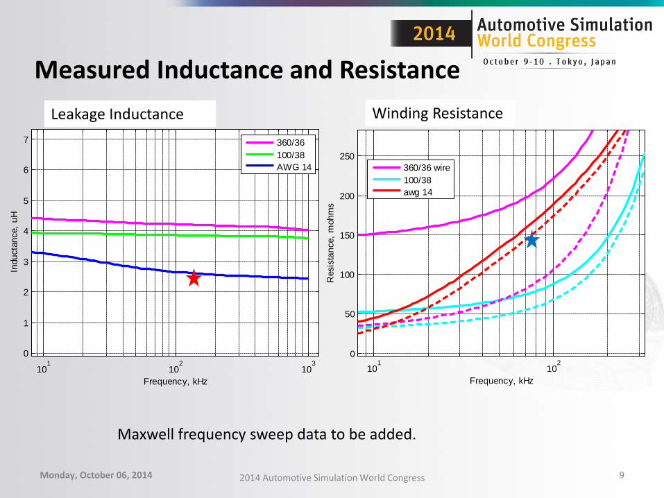
Measured Inductance and Resistance
Monday, October 06, 2014 2014 Automotive Simulation World Congress 9
Leakage Inductance Winding Resistance
Maxwell frequency sweep data to be added.

Determine Leakage and Magnetizing
• Mesh size =1.1 million tets
Monday, October 06, 2014 2014 Automotive Simulation World Congress 10
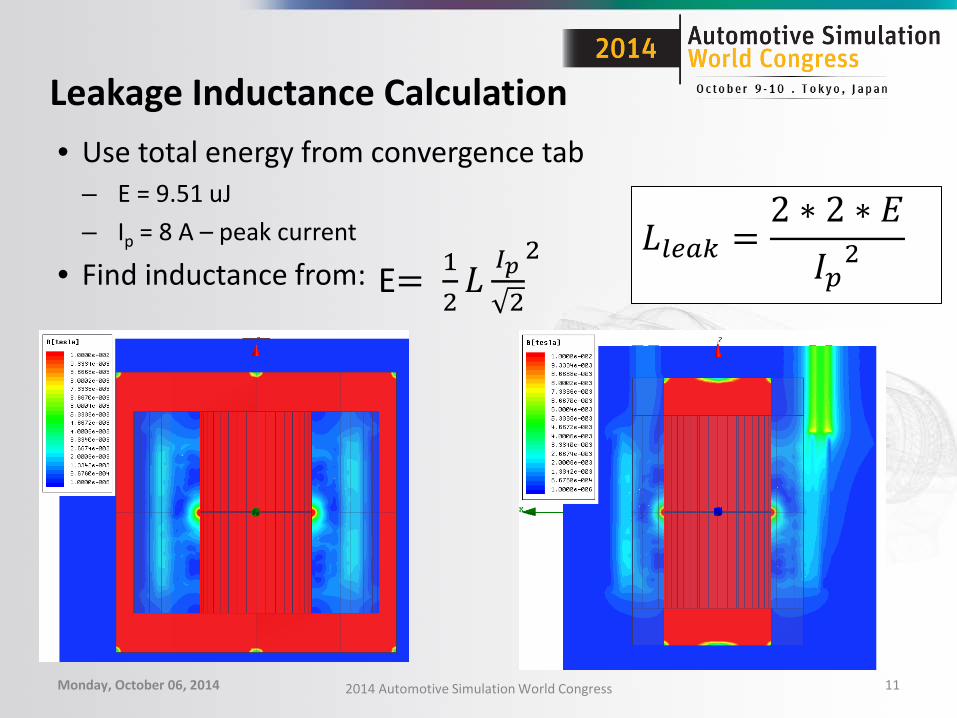
Leakage Inductance Calculation • Use total energy from convergence tab
– E = 9.51 uJ – Ip = 8 A – peak current
• Find inductance from:
Monday, October 06, 2014 2014 Automotive Simulation World Congress 11
E= 12𝐿 𝐼𝑝
2
2
𝐿𝑙𝑙𝑙𝑙 =2 ∗ 2 ∗ 𝐸𝐼𝑝2
Core Saturation Simulation
• Plot of inductance vs current • Field animation of saturation effects
Monday, October 06, 2014 2014 Automotive Simulation World Congress 12
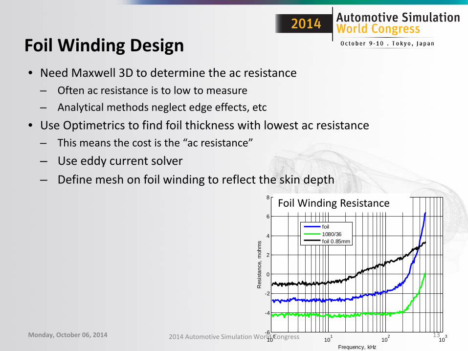
Foil Winding Design • Need Maxwell 3D to determine the ac resistance
– Often ac resistance is to low to measure – Analytical methods neglect edge effects, etc
• Use Optimetrics to find foil thickness with lowest ac resistance – This means the cost is the “ac resistance” – Use eddy current solver – Define mesh on foil winding to reflect the skin depth
Monday, October 06, 2014 2014 Automotive Simulation World Congress 13 10
010
110
210
3-6
-4
-2
0
2
4
6
8
Frequency, kHz
Res
ista
nce,
moh
ms
foil1080/36foil 0.85mm
Foil Winding Resistance
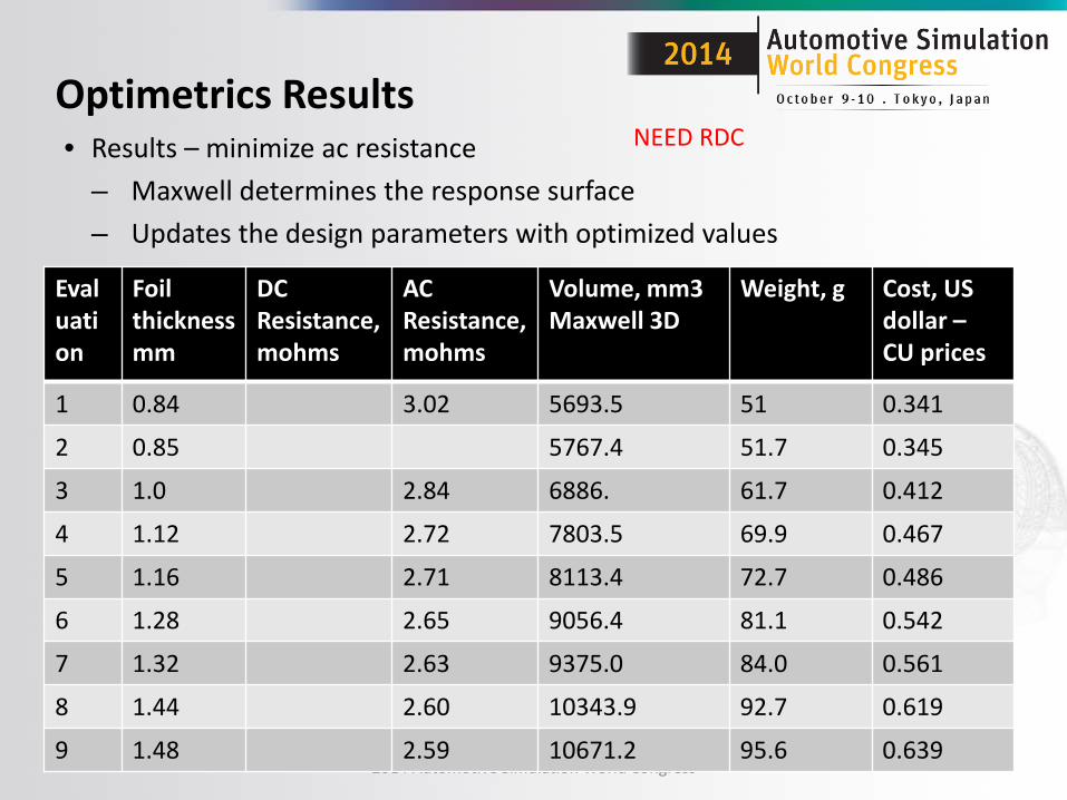
Optimetrics Results • Results – minimize ac resistance
– Maxwell determines the response surface – Updates the design parameters with optimized values
Monday, October 06, 2014 2014 Automotive Simulation World Congress 14
Evaluation
Foil thicknessmm
DC Resistance, mohms
AC Resistance, mohms
Volume, mm3 Maxwell 3D
Weight, g Cost, US dollar – CU prices
1 0.84 3.02 5693.5 51 0.341
2 0.85 5767.4 51.7 0.345
3 1.0 2.84 6886. 61.7 0.412
4 1.12 2.72 7803.5 69.9 0.467
5 1.16 2.71 8113.4 72.7 0.486
6 1.28 2.65 9056.4 81.1 0.542
7 1.32 2.63 9375.0 84.0 0.561
8 1.44 2.60 10343.9 92.7 0.619
9 1.48 2.59 10671.2 95.6 0.639
NEED RDC
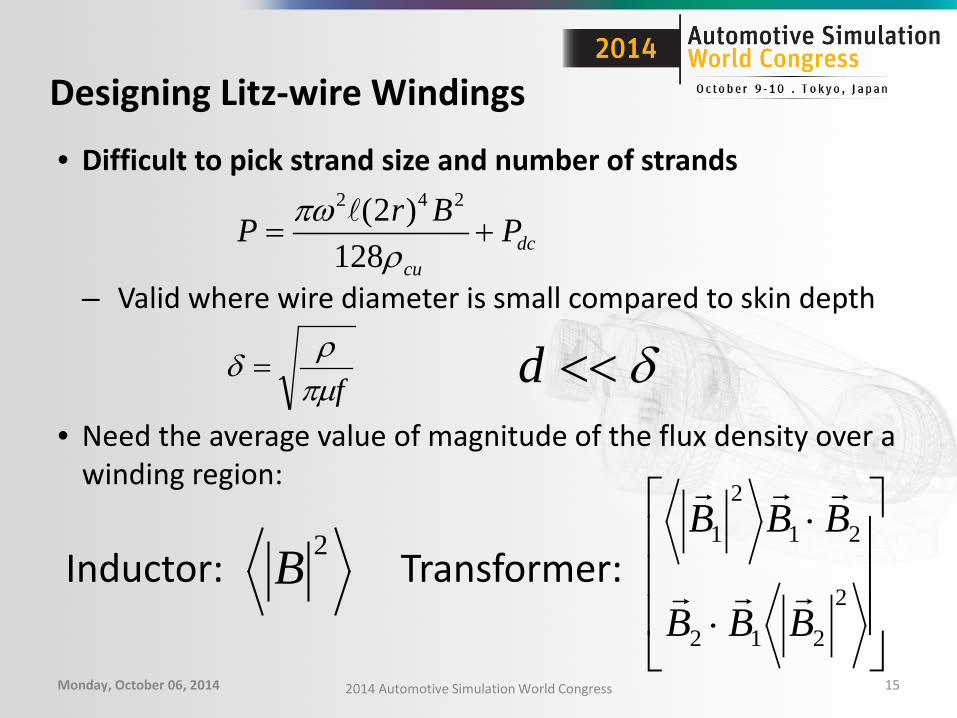
Designing Litz-wire Windings
• Difficult to pick strand size and number of strands
– Valid where wire diameter is small compared to skin depth • Need the average value of magnitude of the flux density over a
winding region:
Monday, October 06, 2014 2014 Automotive Simulation World Congress 15
dccu
PBrP +=ρ
πω128
)2( 242
fπµρδ = δ<<d
2B
⋅
⋅
2
212
21
2
1
BBB
BBB
Inductor: Transformer:
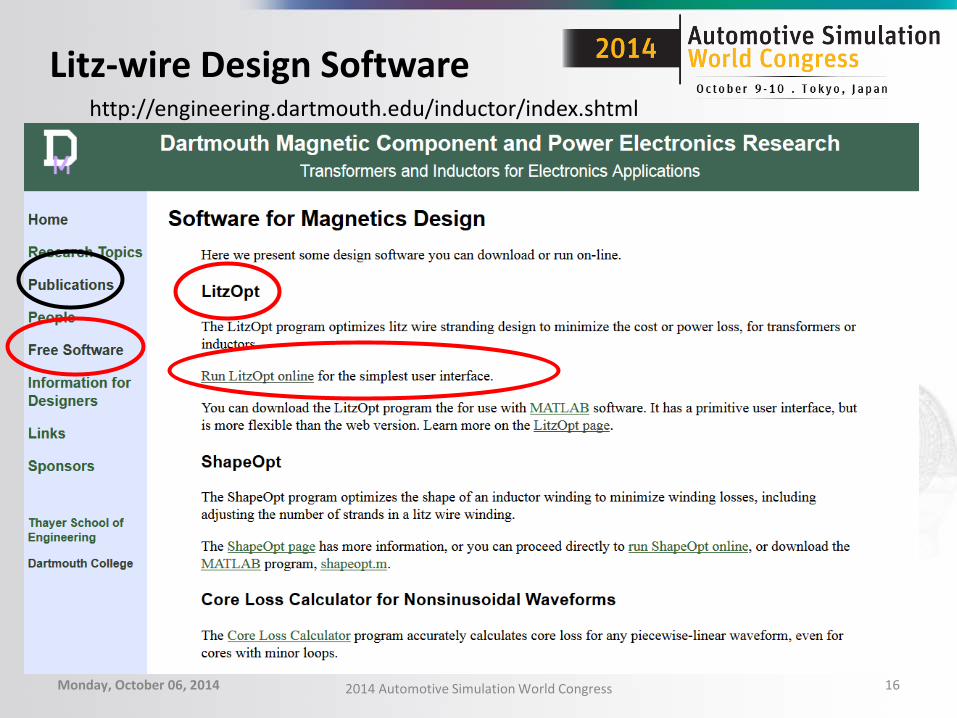
Litz-wire Design Software
Monday, October 06, 2014 2014 Automotive Simulation World Congress 16
http://engineering.dartmouth.edu/inductor/index.shtml

User Supplied Magnetic Field Data
• Use magnetostatic simulations
Monday, October 06, 2014 2014 Automotive Simulation World Congress 17
Both windings conduct with equal and opposite unit N*I
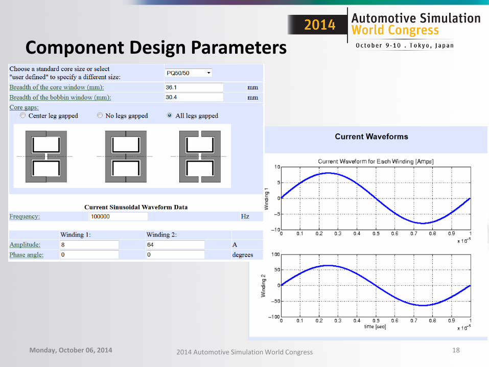
Component Design Parameters
Monday, October 06, 2014 2014 Automotive Simulation World Congress 18
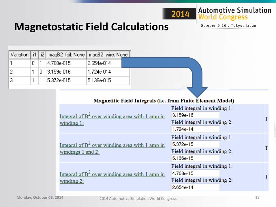
Magnetostatic Field Calculations
Monday, October 06, 2014 2014 Automotive Simulation World Congress 19

Winding Design Proposals
• Total winding loss = 2.5 W – Now tradeoff
• Cost • Loss • Temperature rise • Weight
– To pick the optimal stranding for design specifications
Monday, October 06, 2014 2014 Automotive Simulation World Congress 20

Compare Cost and Weight Windings design Weight, g
measured* Volume, mm3 Maxwell 3D
Rdc, mohms Rac ,at 120 kHz
N=2: 5 mil foil 12.63 1.8
N=2: 0.85 mm foil 61.23 0.224
N=2: 1080/36 37.94 0.310
N=16: 360/36 76.65 5.03
N=16: awg 14 25.52 8.65
N=16: 100/38 11.13 23.19
Monday, October 06, 2014 2014 Automotive Simulation World Congress 21
Integrate Results into Thermal Simulations
• Simulation running now
Monday, October 06, 2014 2014 Automotive Simulation World Congress 22

Conclusions
Monday, October 06, 2014 2014 Automotive Simulation World Congress 23
• Maxwell 3D powerful tool for power magnetic component design
• Provides insight into field patterns and current distributions at high frequency
• Optimetrics package increase ability to design intelligently with FEA
• Parametric extremely useful for sweeping variables
Thanks and Questions?
• Specials thanks to: – Will Shultz, Pavani Gottipati, ANSYS – Lev Fedoseyev, Tesla Motors – My team, Tesla Motors – Thorben Schobre, Intern, Tesla Motors – Dr. Charles Sullivan, Dartmouth Magnetic Component and
Power Electronics Research Group
Monday, October 06, 2014 2014 Automotive Simulation World Congress 24
References
• J. Pollock, T. Abdallah and C. R. Sullivan, “Easy-To-Use CAD Tools for Litz-Wire Winding Optimization”, IEEE Applied Power Electronics Conference, Feb. 2003, pp. 1157 -1163.
• Litzopt: Dartmouth Magnetic Components and Power Electronics http://engineering.dartmouth.edu/inductor/index.shtml
Monday, October 06, 2014 2014 Automotive Simulation World Congress 25