Embed Size (px)
Citation preview

JOURNAL OF LIGHTWAVE TECHNOLOGY, VOL. 24, NO. 4, APRIL 2006 1787
Polarization Properties of InterferometricallyInterrogated Fiber Bragg Grating andTandem-Interferometer Strain Sensors
Geoffrey A. Cranch, Gordon M. H. Flockhart, and Clay K. Kirkendall, Member, IEEE
Abstract—Lead sensitivity in low-coherence interferometricfiber-optic sensors is a well-known problem. It can lead to a severedegradation in the sensor resolution and accuracy through itseffect on the fringe visibility and interferometric phase. Thesesensitivities have been attributed to birefringence in the variouscomponents. In the current work, an analysis of the polariza-tion properties of fiber Bragg grating and tandem-interferometerstrain sensors, using Stokes calculus and the Poincaré sphere,is presented. The responses of these sensors as a function ofthe birefringence properties of the various components underdifferent illuminating conditions are derived. The predicted re-sponses demonstrate very good agreement with experimentallymeasured responses. These models provide a clear insight into theevolution of the polarization states through the sensor networks.Methods to overcome the lead sensitivity are discussed and demon-strated, which yield a differential strain measurement accuracy of18 nε · rms for a fiber Bragg grating sensor.
Index Terms—Birefringence, optical-fiber polarization, opticalinterferometry, optical noise, strain measurement.
I. INTRODUCTION
WHITE-LIGHT interferometric interrogation of fiberBragg grating (FBG) strain sensors has been demon-
strated as a high-resolution method of decoding the strain-induced change in Bragg resonance for both single [1] andmultiplexed [2] sensors. White-light tandem interferometryhas also been applied to coherence multiplexed extrinsic fiberFabry–Pérot (FFP) strain sensors [3] and time division mul-tiplexed FBG FP sensors [4]. These sensor systems utilize adecoding interferometer to recover the signal from the opticalsensor. In the case of the FBG sensor, the decoding interfer-ometer converts the change in wavelength of the light reflectedfrom the sensor to a change in intensity. In the white-lighttandem interferometer, the decoding interferometer balancesthe optical path length of the light reflected from the sensing in-terferometer, yielding an interference signal, which contains thestrain information of interest. It has been noted previously thatthe output of a tandem-interferometer arrangement can exhibitstrong sensitivities to perturbations of the lead connecting thetwo interferometers [5]. This sensitivity manifests itself as fluc-tuations of both the output fringe visibility and interferometric
Manuscript received August 18, 2005; revised January 10, 2006. This workwas supported by the Office of Naval Research.
The authors are with SFA Inc., Crofton, MD, based at the Naval ResearchLaboratory, Washington, DC 20375 USA (e-mail: [email protected]).
Digital Object Identifier 10.1109/JLT.2006.871055
phase. Changes in fringe visibility cause variation in the signal-to-noise ratio and, hence, self-noise of the sensor, whereasphase errors result in strain measurement errors. Lead sensitiv-ity is observed for both polarized and unpolarized illuminationto varying degrees. Gauthier et al. showed that this sensitivityarises due to the presence of birefringence in the decodingand sensing interferometers. They applied the Jones calculusto the tandem interferometer to infer how the birefringencecan affect the fringe visibility and output phase for the caseof a polarized illuminating source. This lead sensitivity is alsocommon to the FBG sensor; however, to the best of the author’sknowledge, no rigorous study has previously been presented.In this case perturbations of the lead connecting the decodinginterferometer to the FBG sensor can give rise to fluctuations ofthe fringe visibility and output phase of the interferometer whenbirefringence is present in the network. Most optical fibersexhibit some intrinsic birefringence, and birefringence can begenerated in the FBG during the writing process [6] or duringthe mounting procedure.
Techniques to overcome these lead-sensitivity effects havesince been demonstrated, such as use of ortho-conjugate mir-rors in the sensing interferometer [7]. Also, scrambling thebirefringence in the lead connecting the two interferometers hasbeen suggested as a method to remove this sensitivity [8]. Anunderstanding of the origins of these sensitivities and a meansto quantify them is particularly important for the successfuloperation of interferometrically interrogated differential strainsensors [9].
The present work examines the polarization properties ofboth the FBG and tandem-interferometer sensors. We showthat by applying the Stokes calculus and through the use ofthe Poincaré-sphere representation of polarized light, the exactresponse of these two sensor systems when illuminated withpolarized, unpolarized, and partially polarized light can bededuced. This is relevant to many systems since broadbandsources often produce unpolarized light or can be depolarizedwith a Lyot depolarizer. Expressions for the fringe visibilityand output phase for both sensors are derived, which includethe effects of birefringence in the decoding interferometer,connecting lead, and sensing interferometer or FBG. Theseprovide measurable quantities that are compared with exper-imental measurements to validate the model. This analysisprovides a greatly improved understanding of the propertiesof these sensor systems and indicates the permissible levels ofbirefringence given a particular performance criterion.
0733-8724/$20.00 © 2006 IEEE

1788 JOURNAL OF LIGHTWAVE TECHNOLOGY, VOL. 24, NO. 4, APRIL 2006
Fig. 1. (a) Typical arrangement of an FBG or MI strain sensor system,(b) equivalent birefringent network of the sensor systems, (c) FBG sensor withinput DOP control, (d) Poincaré-sphere representation of the input and outputpolarization states of the MZI, and (e) Poincaré-sphere representation of theinput and output polarization states of the FBG.
The manuscript is arranged as follows. Section II outlinesthe principles of interferometrically interrogated FBGs andtandem-interferometer arrangements. Section III presents thebirefringence model for the FBG sensors and discusses thesensor response under various illumination conditions. Exper-imental measurements are then presented. Section IV appliesthe same model to the tandem-interferometer arrangement.Section V discusses the techniques that can be used to improvethe sensor performance, and finally, the conclusions are sum-marized in Section VI. Please note that the equations derived inthe appendices are labeled (A∗) or (B∗).
II. INTERFEROMETRIC INTERROGATION
A typical arrangement of the interferometrically interrogatedFBG sensor is shown in Fig. 1(a). The emission from a broad-band source is injected into a Mach–Zehnder interferometer(MZI). The output propagates along a connecting lead throughan optical circulator and is reflected by the FBG to be sepa-rated on return through the circulator. The FBG narrows theoptical spectrum, such that an interference signal is generated.
An interrogation approach, such as phase-generated carrier orpseudo-heterodyne detection, is used to extract the interfero-metric phase. If the system is lossless, and the coupler ratiosare exactly 50%, the output intensity is given by
I =R
2I0 (1 + V cos(φMZI + φFBG)) (1)
where I0 is the input intensity, R is the power reflectivity ofthe FBG, V is a fringe-visibility term described below, andφMZI and φFBG are phase shifts associated with the MZI andFBG, respectively. Phase shifts in the MZI may arise fromtemperature changes or vibration and acoustics. These phaseshifts can be rejected by interrogating a second FBG with theremaining output of the MZI and measuring the differencein phase between the two outputs [1]. The component of themeasured phase associated with the FBG is related to theapplied strain ∆ε by
∆φFBG =2πndMZI
λB(0.78)∆ε (2)
where n is the effective refractive index of the fiber, dMZI isthe path imbalance in the MZI, λB is the Bragg wavelength ofthe FBG, and the factor of 0.78 takes into account the stress-optic effect [10]. If the MZI is free from birefringence, thenthe fringe visibility is given by V = exp(−τ2/4τ2
c ), whereτ = ndMZI/c is the differential time delay, and τc = 1/(4π∆f)is the coherence time of the light reflected from the FBG.∆f is the rms half width of the reflected line shape, whichfor a Gaussian beam shape is related to the full-width halfmaximum ∆λFWHM by ∆f = c∆λFWHM/(4
√ln 2λ2
B) [11].For ∆λFWHM = 0.2 nm and dMZI = 3 mm, a visibility greaterthan 0.6 is obtained.
If the FBG is replaced with a Michelson interferometer (MI)and the optical path difference (OPD) in the MZI is balancedwith the OPD of the MI, then the output intensity is
I =12I0
(1 +
V
2cos(φMZI + φMI)
). (3)
In practice, the OPD of the MI and MZI may not be ex-actly balanced, and the difference between the two is definedas the effective OPD of the system. The component of themeasured phase associated with the MI is related to the appliedstrain ∆ε by
∆φMI =4πndMI
λB(0.78)∆ε (4)
where dMI is the MI fiber length coupled to the strain. It isassumed that the bandwidth of the input radiation in the tandeminterferometer is narrowed sufficiently to obtain coherent inter-ference. Interference is observed when the coherence length ofthe input radiation is less than the effective OPD.
When birefringence is present in the interferometers andconnecting leads, an extra multiplicative term must be in-cluded in the fringe visibility and an extra phase term added

CRANCH et al.: PROPERTIES OF INTERROGATED FBG AND TANDEM-INTERFEROMETER STRAIN SENSORS 1789
to the interferometer phase to account for these polariza-tion related effects. The remainder of this paper investigatesthese terms.
III. FBG SENSOR
The interferometrically interrogated FBG sensor can be an-alyzed by utilizing the model presented by Kersey et al. [12],[13] for investigating the polarization properties of fiber-opticinterferometers. In this model, the birefringence properties ofthe MZI are represented by a single birefringent element inone arm of the interferometer, as shown in Fig. 1(b); the otherarm appearing isotropic to the propagating field. This element,denoted MZI(ΩMZI), is a 4 × 4 Mueller matrix and repre-sents a general elliptic retarder of rotational magnitude (phasedelay) ΩMZI, which represents the “differential birefringence”in the MZI. The eigenvectors of this matrix represent the twoeigenaxes of the MZI corresponding to orthogonal polarizationaxes. When an input state Ci is coincident with the eigenaxesof MZI, it remains invariant in the transformation to C ′
i, andoptimum fringe visibility is obtained. When Ci is not coincidentwith an eigenaxis, and subtends an angle θ to MZI, it istransformed to a new state C ′
i. This is represented on thePoincaré sphere as a rigid rotation about MZI by an angleΩMZI, as shown in Fig. 1(d). The birefringence in the input fiberis denoted i, and the birefringence in the connecting fiber isdenoted l(Ωl). In the current work, this model is extended toincorporate birefringence in the FBG and used to explain howsensitivities in the connecting leads arise for varying degreesof polarization of the incident light. The derivation of thegeneral response of an FBG interrogated with polarized andunpolarized light is given in Appendix A. The remainder of thissection will study the specific cases of this general response.
A. Illumination With Polarized Light
The general response of an FBG sensor illuminated withpolarized light is given by (A3). The output intensity for anideal birefringence-free FBG is given by setting ΩFBG = 0in (A3). This yields the equation for a birefringent fiber-opticinterferometer illuminated with polarized light, as derived in[12], [13]
I =R
2I0
(1 +
1 − sin2 θ sin2
(ΩMZI
2
) 12
× cos (∆φFBG(λB) − γ)
)(5)
where tan γ = tan(ΩMZI/2) cos θ. The fringe visibility Vis therefore 1 − sin2 θ sin2(ΩMZI/2)1/2. Thus, referring toFig. 1(b), both the fringe visibility and interferometric phasedepend on the birefringence properties of the MZI throughΩMZI and input SOP: Ci through θ. In the absence of birefrin-gence in the FBG, the fringe visibility and interferometric phasewill be sensitive only to perturbations in the input fiber, whichwill change Ci.
Conversely, the case of the birefringence-free MZI with abirefringent FBG can be determined by setting ΩMZI = 0 in(A3). This yields
I =R
2I0 ·
(1 +
1 − sin2 ϕ sin2
(ΩFBG
2
) 12
× cos(∆φ(λ) + γ
))(6)
where tan γ = tan(ΩFBG/2) cos ϕ. λ is the mean wave-
length of the FBG, and ΩFBG = 2πnd∆λ/λ2
is related tothe birefringence in the FBG; these are described furtherin Appendix A. The fringe visibility V is therefore 1 −sin2 ϕ sin2(ΩFBG/2)1/2. In this model, ϕ is the angle sub-tended by the birefringent axis of the FBG FBG to MZI.On adding birefringence to the FBG, the visibility and phasebecome dependent on the birefringent properties of the FBGthrough ΩFBG and input SOP to the FBG: C ′′
i through ϕ.Birefringence in the input fiber will also change C ′′
i . Thus,perturbations to the input fiber and connecting fiber will affectboth the visibility and phase.
Thus, with polarized illumination, measurement errors mayarise from perturbations of the input lead to the MZI andconnecting lead between the MZI and FBG or changes inbirefringence in the MZI or FBG.
B. Illumination With Unpolarized Light
The general expression for the output intensity due to unpo-larized illumination1 is given by (A7). When the polarizationeigenaxes of the MZI and FBG are parallel (+) or orthogonal(−), (A7) can be further simplified to
IUP± =
R
2I0
(1 + cos
(ΩMZI
2± ΩFBG
2
)cos ∆φ(λ)
). (7)
The maximum and minimum visibilities are given by the termV± = cos(ΩMZI/2 ± ΩFBG/2). Thus, the birefringence in theMZI combines with the birefringence in the FBG to determinethe fringe visibility. When birefringence is present in the con-necting lead such that Ωl = 0 (mod2π), the visibility will bewithin these two limits. The interferometric phase is inverselyproportional to the mean wavelength λ.
Several important conclusions can be drawn from this re-sult. On illumination with the unpolarized light, the phasemeasurement is independent of the birefringence in the inputfiber. In a purely birefringent sensor network with no dicroism,changes in the birefringence of the connecting lead, MZI, orFBG will only affect the fringe visibility. The interferometricphase, being inversely proportional to the mean Bragg wave-length, is therefore independent of the birefringence in the
1The term unpolarized light is often used to refer to light that exhibits apolarization state that changes rapidly during the observation time. In the caseof natural light, these changes are random, which leads to the term randomlypolarized. We use the term unpolarized to refer to light with a zero degree ofpolarization measured over a specified observation time.

1790 JOURNAL OF LIGHTWAVE TECHNOLOGY, VOL. 24, NO. 4, APRIL 2006
MZI, FBG, and connecting lead. Thus, the presence of purebirefringence will not lead to measurement error when theilluminating source is unpolarized and the network free fromdicroism.
C. Illumination With Partially Polarized Light
In practical systems, the degree of polarization (DOP) maynot always be maintained at zero throughout the system. Thebroadband source may exhibit a small DOP, yielding partiallypolarized light, and the components making up the system mayeach exhibit some polarization dependent loss (PDL). If PDLis present, the DOP will change on propagation through thenetwork. Also, if PDL is present in several components, thenthe total PDL at any given time will depend on the birefringencein the system at that time. Here, we consider the case of partiallypolarized input light and ideal components (i.e., PDL free). Inthis case, the amplitudes of the two orthogonal waves, given by(A5), may not be exactly matched at the detector. The outputintensity for partially polarized illumination is expressed as
IPP = I1 + x · I2 (8)
where from the definition of the Stokes parameters, x is relatedto the DOP by x = (1 − DOP)/(1 + DOP). Assuming that I1
is aligned to an eigenaxis of the MZI, then summing the twointensities given by (A5) using (8) yields
IPP =R
4I0
(1 + x + cos2
(ϕ
2
)
·[cos(
φ +ΩFBG
2+
ΩMZI
2
)
+ x cos(
φ − ΩFBG
2− ΩMZI
2
)]+ sin2
(ϕ
2
)
·[cos(
φ − ΩFBG
2+
ΩMZI
2
)
+ x cos(
φ +ΩFBG
2− ΩMZI
2
)]). (9)
We consider the practical case where ΩMZI is set to zero. Themaximum phase error is given by the difference in measuredphase when the component axes of the partially polarized lightand FBG eigenaxes are parallel and orthogonal. This phaseerror can be determined by calculating IPP
± for each case bysetting ϕ to zero and π in (9), yielding
IPP± =
R
4I0
(1 + x +
1 + 2x cos(ΩFBG) + x2
12
· cos(∆φ(λ) + δ))
(10)
where
δ± = tan−1
[DOP tan
(±ΩFBG
2
)]. (11)
Fig. 2. Fringe visibility as a function of FBG peak splitting for a polarizedand unpolarized source.
The maximum phase error is therefore given by |δ+ − δ−|.The measurement error drifts between the two values of δ+
and δ− due to changes in the birefringence in the input andconnecting lead. Thus, illumination with partially polarizedlight will give rise to both measurement error and drift.
D. Experiment
To confirm the models presented above, the fringe visibilityand phase error have been measured as a function of FBGand MZI birefringence. In the first experiment, birefringencein the MZI is minimized by replacing it with an MI with ortho-conjugate or Faraday mirrors, such that ΩMZI
∼= 0(modulo 2π).An increasing level of birefringence is generated in the FBGby applying a transverse force, using a similar method to thatdescribed in [14]. The FBG is stripped of its acrylate coatingbefore force is applied through a loading plate. The fringevisibility is then measured as a function of applied force,using the set-up shown in Fig. 1(a). The broadband sourceis an erbium-doped fiber amplifier (EDFA) with a DOP lessthan 3%, and the Bragg grating is approximately 3 mm inlength, written into SMF-28 fiber with a peak reflectivity of1% and λB = 1549 nm. The peak splitting ∆λ of the Braggwavelength with applied force is initially measured with anoptical spectrum analyzer, and the visibility is calculated fromV = cos(πnd∆λ/λ2), where n = 1.465 and d = 6.56 mm.The measured and calculated fringe visibilities as a function ofpeak splitting ∆λ are shown in Fig. 2. A very good agreementis obtained between the predicted and measured visibilities.The visibility is plotted for both increasing and decreasingFBG birefringence. The good repeatability obtained indicatesthat the FBG loading arrangement exhibits minimal hystere-sis. This experiment is repeated for a polarized source byplacing a polarizer at the output of the EDFA, which yieldeda DOP ∼ 90%. In this configuration, the visibility will be givenby V = 1 − sin2 ϕ sin2(ΩFBG/2)1/2 and, thus, will varybetween the limits of unity and cos(πnd∆λ/λ2) dependingon the birefringence in the connecting lead. This is variedusing a birefringence controller placed in the connecting fiber.The visibility is extinguished when ΩFBG = 2πnd∆λ/λ2 =π(modulo 2π).
CRANCH et al.: PROPERTIES OF INTERROGATED FBG AND TANDEM-INTERFEROMETER STRAIN SENSORS 1791
Fig. 3. Maximum and minimum visibilities as a function of ΩFBG and MZIbirefringence.
In the second experiment, a fixed amount of birefringenceis added to the MZI using a birefringence controller placed inone arm of the MZI, when the FBG is free from birefringenceand the source unpolarized. In this configuration, the fringevisibility is given by V = cos(ΩMZI/2). Increasing levels ofbirefringence are then added to the FBG, and the limits ofthe fringe visibility are recorded when the birefringence inthe connecting lead is changed. The result is plotted in Fig. 3along with the limits of the fringe visibility calculated withV = cos(ΩMZI/2 ± ΩFBG/2) from (7). Here, we have usedd = 3.6 mm to calculate ΩFBG. Also plotted for comparisonis the curve for ΩMZI = 0.
A very good agreement is obtained with the predicted vis-ibility. Note that when the FBG birefringence is increased toreach the visibility limit of zero or unity, further increase inΩFBG results in this limit being maintained for certain values ofconnecting lead birefringence. The visibility limit is thereforenot periodic and the visibility limits of zero and unity willbe obtained when ΩMZI/2 ± ΩFBG/2 equals π/2 and zero,respectively.
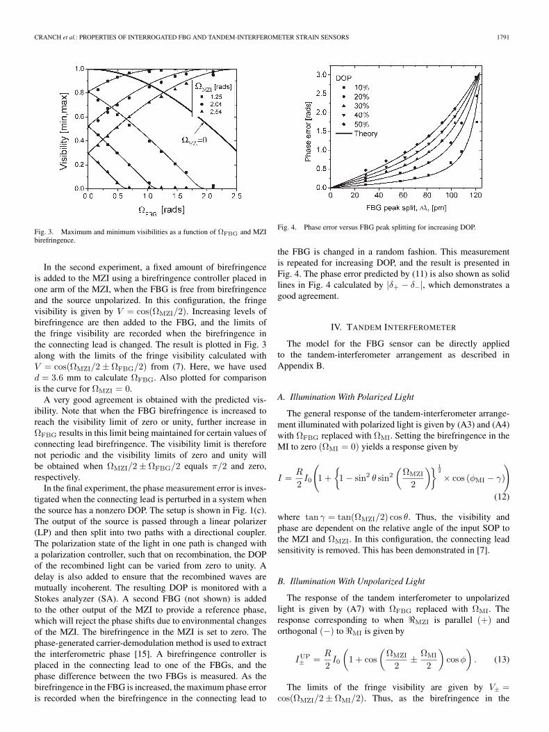
In the final experiment, the phase measurement error is inves-tigated when the connecting lead is perturbed in a system whenthe source has a nonzero DOP. The setup is shown in Fig. 1(c).The output of the source is passed through a linear polarizer(LP) and then split into two paths with a directional coupler.The polarization state of the light in one path is changed witha polarization controller, such that on recombination, the DOPof the recombined light can be varied from zero to unity. Adelay is also added to ensure that the recombined waves aremutually incoherent. The resulting DOP is monitored with aStokes analyzer (SA). A second FBG (not shown) is addedto the other output of the MZI to provide a reference phase,which will reject the phase shifts due to environmental changesof the MZI. The birefringence in the MZI is set to zero. Thephase-generated carrier-demodulation method is used to extractthe interferometric phase [15]. A birefringence controller isplaced in the connecting lead to one of the FBGs, and thephase difference between the two FBGs is measured. As thebirefringence in the FBG is increased, the maximum phase erroris recorded when the birefringence in the connecting lead to
Fig. 4. Phase error versus FBG peak splitting for increasing DOP.
the FBG is changed in a random fashion. This measurementis repeated for increasing DOP, and the result is presented inFig. 4. The phase error predicted by (11) is also shown as solidlines in Fig. 4 calculated by |δ+ − δ−|, which demonstrates agood agreement.
IV. TANDEM INTERFEROMETER
The model for the FBG sensor can be directly appliedto the tandem-interferometer arrangement as described inAppendix B.
A. Illumination With Polarized Light
The general response of the tandem-interferometer arrange-ment illuminated with polarized light is given by (A3) and (A4)with ΩFBG replaced with ΩMI. Setting the birefringence in theMI to zero (ΩMI = 0) yields a response given by
I =R
2I0
(1 +
1 − sin2 θ sin2
(ΩMZI
2
) 12
× cos (φMI − γ)
)(12)
where tan γ = tan(ΩMZI/2) cos θ. Thus, the visibility andphase are dependent on the relative angle of the input SOP tothe MZI and ΩMZI. In this configuration, the connecting leadsensitivity is removed. This has been demonstrated in [7].
B. Illumination With Unpolarized Light
The response of the tandem interferometer to unpolarizedlight is given by (A7) with ΩFBG replaced with ΩMI. Theresponse corresponding to when MZI is parallel (+) andorthogonal (−) to MI is given by
IUP± =
R
2I0
(1 + cos
(ΩMZI
2± ΩMI
2
)cos φ
). (13)
The limits of the fringe visibility are given by V± =cos(ΩMZI/2 ± ΩMI/2). Thus, as the birefringence in the
1792 JOURNAL OF LIGHTWAVE TECHNOLOGY, VOL. 24, NO. 4, APRIL 2006
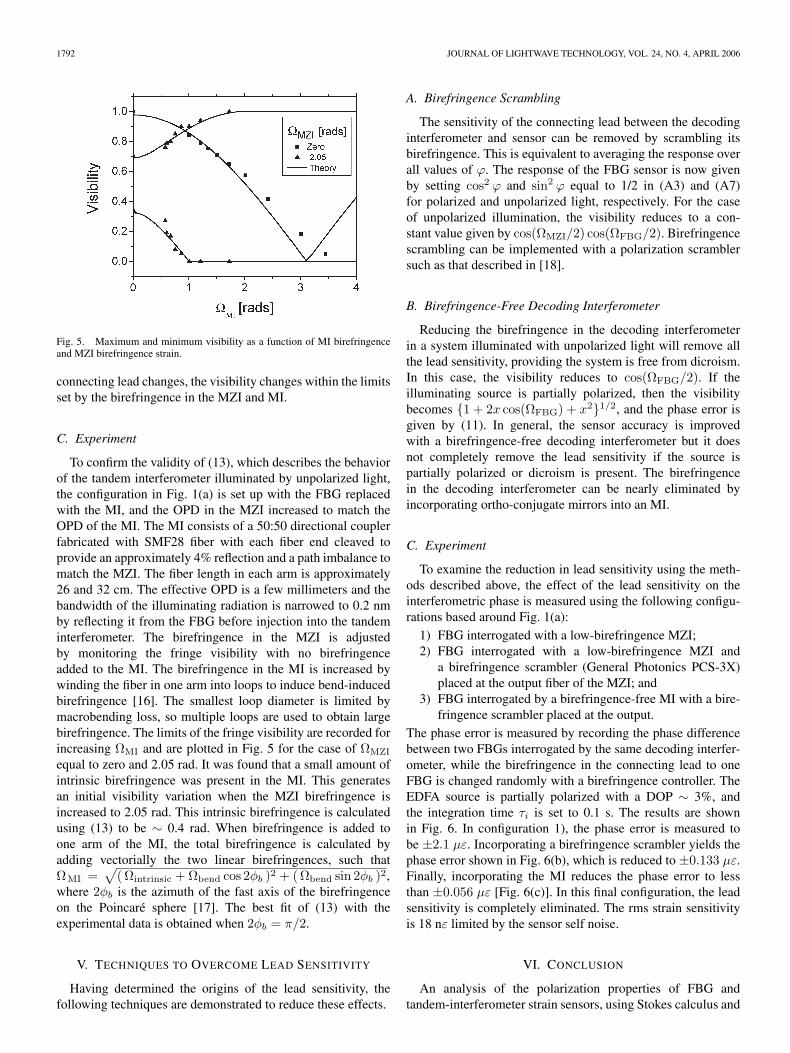
Fig. 5. Maximum and minimum visibility as a function of MI birefringenceand MZI birefringence strain.
connecting lead changes, the visibility changes within the limitsset by the birefringence in the MZI and MI.
C. Experiment
To confirm the validity of (13), which describes the behaviorof the tandem interferometer illuminated by unpolarized light,the configuration in Fig. 1(a) is set up with the FBG replacedwith the MI, and the OPD in the MZI increased to match theOPD of the MI. The MI consists of a 50:50 directional couplerfabricated with SMF28 fiber with each fiber end cleaved toprovide an approximately 4% reflection and a path imbalance tomatch the MZI. The fiber length in each arm is approximately26 and 32 cm. The effective OPD is a few millimeters and thebandwidth of the illuminating radiation is narrowed to 0.2 nmby reflecting it from the FBG before injection into the tandeminterferometer. The birefringence in the MZI is adjustedby monitoring the fringe visibility with no birefringenceadded to the MI. The birefringence in the MI is increased bywinding the fiber in one arm into loops to induce bend-inducedbirefringence [16]. The smallest loop diameter is limited bymacrobending loss, so multiple loops are used to obtain largebirefringence. The limits of the fringe visibility are recorded forincreasing ΩMI and are plotted in Fig. 5 for the case of ΩMZI
equal to zero and 2.05 rad. It was found that a small amount ofintrinsic birefringence was present in the MI. This generatesan initial visibility variation when the MZI birefringence isincreased to 2.05 rad. This intrinsic birefringence is calculatedusing (13) to be ∼ 0.4 rad. When birefringence is added toone arm of the MI, the total birefringence is calculated byadding vectorially the two linear birefringences, such thatΩMI =
√(Ωintrinsic + Ωbend cos 2φb )2 + (Ωbend sin 2φb )2,
where 2φb is the azimuth of the fast axis of the birefringenceon the Poincaré sphere [17]. The best fit of (13) with theexperimental data is obtained when 2φb = π/2.
V. TECHNIQUES TO OVERCOME LEAD SENSITIVITY
Having determined the origins of the lead sensitivity, thefollowing techniques are demonstrated to reduce these effects.
A. Birefringence Scrambling
The sensitivity of the connecting lead between the decodinginterferometer and sensor can be removed by scrambling itsbirefringence. This is equivalent to averaging the response overall values of ϕ. The response of the FBG sensor is now givenby setting cos2 ϕ and sin2 ϕ equal to 1/2 in (A3) and (A7)for polarized and unpolarized light, respectively. For the caseof unpolarized illumination, the visibility reduces to a con-stant value given by cos(ΩMZI/2) cos(ΩFBG/2). Birefringencescrambling can be implemented with a polarization scramblersuch as that described in [18].
B. Birefringence-Free Decoding Interferometer
Reducing the birefringence in the decoding interferometerin a system illuminated with unpolarized light will remove allthe lead sensitivity, providing the system is free from dicroism.In this case, the visibility reduces to cos(ΩFBG/2). If theilluminating source is partially polarized, then the visibilitybecomes 1 + 2x cos(ΩFBG) + x21/2, and the phase error isgiven by (11). In general, the sensor accuracy is improvedwith a birefringence-free decoding interferometer but it doesnot completely remove the lead sensitivity if the source ispartially polarized or dicroism is present. The birefringencein the decoding interferometer can be nearly eliminated byincorporating ortho-conjugate mirrors into an MI.
C. Experiment
To examine the reduction in lead sensitivity using the meth-ods described above, the effect of the lead sensitivity on theinterferometric phase is measured using the following configu-rations based around Fig. 1(a):
1) FBG interrogated with a low-birefringence MZI;2) FBG interrogated with a low-birefringence MZI and
a birefringence scrambler (General Photonics PCS-3X)placed at the output fiber of the MZI; and
3) FBG interrogated by a birefringence-free MI with a bire-fringence scrambler placed at the output.
The phase error is measured by recording the phase differencebetween two FBGs interrogated by the same decoding interfer-ometer, while the birefringence in the connecting lead to oneFBG is changed randomly with a birefringence controller. TheEDFA source is partially polarized with a DOP ∼ 3%, andthe integration time τi is set to 0.1 s. The results are shownin Fig. 6. In configuration 1), the phase error is measured tobe ±2.1 µε. Incorporating a birefringence scrambler yields thephase error shown in Fig. 6(b), which is reduced to ±0.133 µε.Finally, incorporating the MI reduces the phase error to lessthan ±0.056 µε [Fig. 6(c)]. In this final configuration, the leadsensitivity is completely eliminated. The rms strain sensitivityis 18 nε limited by the sensor self noise.
VI. CONCLUSION
An analysis of the polarization properties of FBG andtandem-interferometer strain sensors, using Stokes calculus and

CRANCH et al.: PROPERTIES OF INTERROGATED FBG AND TANDEM-INTERFEROMETER STRAIN SENSORS 1793
Fig. 6. Strain error due to lead sensitivity for (a) FBG interrogated with lowbirefringence MZI and unpolarized light, (b) same as (a) with birefringencescrambler in connecting lead, and (c) MZI replaced with birefringence-free MIand birefringence scrambler in the connecting lead.
the Poincaré sphere, has been presented. The responses of thesesensors as a function of the birefringence properties of the var-ious components, under different illuminating conditions, havebeen derived and confirmed with experiment. Methods to over-come the lead sensitivity based on reducing the birefringence inthe decoding interferometer and birefringence scrambling arediscussed and demonstrated. This has demonstrated differentialstrain-measurement accuracy between two FBG sensors equalto 18 nε · rms (τi = 0.1 s).
APPENDIX ADERIVATION OF THE RESPONSE OF AN
INTERFEROMETRICALLY INTERROGATED FBG
The output intensity of the FBG sensor with a polarizedsource is calculated by resolving the input SOP into two orthog-onal components that are coincident with the eigenaxes of theMZI. The response for each component is then calculated andthe result summed to yield the overall response. The birefrin-gence model of the network is shown schematically in Fig. 1(b).To simplify the problem, it is assumed that the birefringencein the connecting lead between the MZI and FBG, describedby l(Ωl), acts to rotate the eigenaxes of the FBG relative tothe MZI. The birefringence in the FBG can be described by aMueller matrix FBG(ΩFBG), where ΩFBG relates to the indexdifference between the two birefringent axes. Thus, l is set tobe aligned with FBG. Although this does not depict exactly theevolution of the field SOPs through the network, it simplifiesthe analysis of this network without loss of generality.
The birefringent Bragg grating is modeled by assigning areflectivity and resonance wavelength for each polarizationeigenaxis of the grating. Thus, the peak reflectivity for eachaxis is set equal to R. The resonance wavelengths for each axisare denoted λ1 and λ2 and the difference in Bragg resonanceas ∆λ = λ2 − λ1. The mean wavelength is defined as λ =(λ2 + λ1)/2. The difference in Bragg resonance encountered
by two orthogonal SOPs coincident with the FBG eigenaxesleads to a phase difference between them given by 2πnd∆λ/λ2
when the FBG is interferometrically interrogated. This phasedifference is defined as ΩFBG. Thus, the relevant birefringentproperties of the system are described by four parameters: ΩMZI
and ΩFBG describe the birefringent properties of the MZI andFBG, respectively; θ is the angle subtended by the great arcjoining the SOP input to the MZI, Ci, and MZI; and ϕ is theangle subtended by the great arc joining MZI and FBG whenmapped onto the Poincaré sphere. These are shown in Fig. 1(d)and (e), respectively. The response is derived by noting that twoorthogonal SOPs coincident with the eigenaxes of the MZI exitwith an interferometric phase difference between them equal toΩMZI. Each output SOP is then resolved into two orthogonalcomponents coincident with the eigenaxes of the FBG. Thus,the output intensity corresponding to the two components ofthe input SOP are
Ia =R
4I0
cos2
(ϕ
2
)cos2
(θ
2
)
×(
1 + cos(
φ(λ) +ΩFBG
2+
ΩMZI
2
))
+ sin2(ϕ
2
)cos2
(θ
2
)
×(
1 + cos(
φ(λ) − ΩFBG
2+
ΩMZI
2
))
Ib =R
4I0
cos2
(ϕ
2
)sin2
(θ
2
)
×(
1 + cos(
φ(λ) − ΩFBG
2− ΩMZI
2
))
+ sin2(ϕ
2
)sin2
(θ
2
)
×(
1 + cos(
φ(λ) +ΩFBG
2− ΩMZI
2
))(A1)
where φ(λ) is the signal phase of interest. The output intensityis given by
I = Ia + Ib (A2)
yielding
I =R
2I0
1 + cos2
(ϕ
2
)1− sin2 θ sin2
(ΩMZI
2+
ΩFBG
2
) 12
× cos(φ(λ) + γ+
)+ sin2
(ϕ
2
)1 − sin2 θ sin2
(ΩMZI
2− ΩFBG
2
) 12
× cos(φ(λ) + γ−
))(A3)

1794 JOURNAL OF LIGHTWAVE TECHNOLOGY, VOL. 24, NO. 4, APRIL 2006
where
tan γ± = tan(
ΩMZI
2± ΩFBG
2
)cos θ. (A4)
The response to an unpolarized source is derived by decom-posing the input beam into two mutually incoherent orthogonallight waves [19]. The response due to each wave is given by(A3). Since the orientation of the two orthogonal componentsof the unpolarized light input to the MZI can be arbitrarilydefined, they can be aligned to the eigenaxes of the MZI. Thisis equivalent to setting θ equal to zero and π in (A3) to obtainthe response for each light wave
IUP1 =
R
4I0
1 + cos2
(ϕ
2
)cos(
φ +ΩFBG
2+
ΩMZI
2
)
+ sin2(ϕ
2
)cos(
φ − ΩFBG
2+
ΩMZI
2
)
IUP2 =
R
4I0
1 + cos2
(ϕ
2
)cos(
φ − ΩFBG
2− ΩMZI
2
)
+ sin2(ϕ
2
)cos(
φ +ΩFBG
2−ΩMZI
2
). (A5)
Summing the two responses such that
IUP = IUP1 + IUP
2 (A6)
yields the output intensity
IUP =R
2I0
1 +
[cos2
(ϕ
2
)cos(
ΩMZI
2+
ΩFBG
2
)
+sin2(ϕ
2
)cos(
ΩMZI
2− ΩFBG
2
)]cos φ(λ)
. (A7)
APPENDIX BDERIVATION OF THE RESPONSE OF A
TANDEM INTERFEROMETER
The analysis of the tandem-interferometer arrangement fol-lows in a similar fashion to the FBG sensor. The birefringencemodel is shown in Fig. 1(b) with the FBG replaced with the MI.The birefringence properties of the system are now described byΩMZI, ΩMI, θ, and ϕ. The differential birefringence in the MZIand MI are described by ΩMZI and ΩMI, respectively. θ is theangle subtended by the input SOP and the eigenaxis of the MZI,and ϕ is the angle between the eigenaxes of the MZI and MI.As before, the birefringent axis of the connecting lead l is setto be parallel with MI. Thus, birefringence in the connectinglead acts to rotate MI relative to MZI .
Following the same procedure as before by resolving theinput SOP into two components coincident with the eigenaxes
of the MZI yields
Ia =R
4I0
cos2
(ϕ
2
)cos2
(θ
2
)
×(
1 + cos(
φ +ΩMI
2+
ΩMZI
2
))
× sin2(ϕ
2
)cos2
(θ
2
)
×(
1 + cos(
φ − ΩMI
2+
ΩMZI
2
))
Ib =R
4I0
cos2
(ϕ
2
)sin2
(θ
2
)
×(
1 + cos(
φ − ΩMI
2− ΩMZI
2
))
× sin2(ϕ
2
)sin2
(θ
2
)
×(
1 + cos(
φ +ΩMI
2− ΩMZI
2
))(B1)
where φ is the phase of the MI. This is the same as (A1) withΩFBG replaced with ΩMI. Thus, substituting ΩMI for ΩFBG
in (A2)–(A7) yields the equivalent response of the tandem-interferometer arrangement.
ACKNOWLEDGMENT
The authors would like to thank C. Askins and A. Tveten forthe very useful discussions.
REFERENCES
[1] A. D. Kersey, T. A. Berkoff, and W. W. Morey, “Fiber-optic Bragggrating strain sensor with drift-compensated high-resolution interfero-metric wavelength-shift detection,” Opt. Lett., vol. 18, no. 1, pp. 72–74,Jan. 1993.
[2] G. A. Johnson, M. D. Todd, B. L. Althouse, and C. C. Chang, “FiberBragg grating interrogation and multiplexing with a 3 × 3 coupler anda scanning filter,” J. Lightw. Technol., vol. 18, no. 8, pp. 1101–1105,Aug. 2000.
[3] F. Farahi, T. P. Newson, J. D. C. Jones, and D. A. Jackson, “Coherencemultiplexing of remote fibre optic Fabry–Pérot sensing system,” Opt.Commun., vol. 65, no. 5, pp. 319–321, Mar. 1988.
[4] G. A. Cranch, G. M. H. Flockhart, and C. K. Kirkendall, “Efficient fiberBragg grating and fiber Fabry–Pérot sensor multiplexing scheme using abroadband, pulsed mode-locked laser,” J. Lightw. Technol., vol. 23, no. 11,pp. 3798–3807, Nov. 2005.
[5] R. R. Gauthier, F. Farahi, and N. Dahi, “Fiber-optic white-light inter-ferometry: Lead sensitivity considerations,” Opt. Lett., vol. 19, no. 2,pp. 138–140, Jan. 1994.
[6] F. Kherbouche and B. Poumellec, “UV-induced stress field during Bragggrating inscription in optical fibres,” J. Opt. A: Pure Appl. Opt., vol. 3,no. 6, pp. 429–439, Nov. 2001.
[7] L. A. Ferrira, J. L. Santos, and F. Farahi, “Polarization insensitivefibre-optic white-light interferometry,” Opt. Commun., vol. 114, no. 5/6,pp. 386–392, Feb. 1995.
[8] E. I. Alekseev and E. N. Bazarov, “White-light interferometry with depo-larization of the radiation,” Tech. Phys. Lett., vol. 23, no. 7, pp. 560–561,Jul. 1997.
[9] G. M. H. Flockhart, G. A. Cranch, and C. K. Kirkendall, “Differentialphase tracking applied to Bragg gratings in multicore fiber for high ac-curacy curvature measurement,” in Proc. SPIE 6167, Symp. Smart Struc-tures and Materials, Smart, Sensor Monitoring Systems and Applications,San Diego, CA, Feb. 26–Mar. 2, 2006.

CRANCH et al.: PROPERTIES OF INTERROGATED FBG AND TANDEM-INTERFEROMETER STRAIN SENSORS 1795
[10] C. D. Butter and G. B. Hocker, “Fiber optic strain gauge,” Appl. Opt.,vol. 17, no. 18, pp. 2867–2869, Sep. 1978.
[11] H. Lefèvre, Fiber-Optic Gyroscope. Boston, MA: Artech House, 1993,sec. A1.7.
[12] A. D. Kersey, M. J. Marrone, A. Dandridge, and A. B. Tveten, “Opti-mization and stabilization of visibility in interferometric fiber-optic sen-sors using input-polarization control,” J. Lightw. Technol., vol. 6, no. 10,pp. 1599–1609, Oct. 1988.
[13] A. D. Kersey, M. J. Marrone, and A. Dandridge, “Analysis of input-polarization-induced phase noise in interferometric fiber optic sensors andits reduction using polarization scrambling,” J. Lightw. Technol., vol. 8,no. 6, pp. 838–845, Jun. 1990.
[14] R. B. Wagreich, W. A. Atia, H. Singh, and J. S. Sirkis, “Effects ofdiametric load on fibre Bragg gratings fabricated in low birefringencefibre,” Electron. Lett., vol. 32, no. 13, pp. 1223–1224, Jun. 1996.
[15] A. Dandridge, A. B. Tveten, and T. G. Giallorenzi, “Homodyne demodu-lation scheme for fiber optic sensors using phase generated carrier,” IEEEJ. Quantum Electron., vol. QE-18, no. 10, pp. 1647–1653, Oct. 1982.
[16] R. Ulrich, S. C. Rashleigh, and W. Eickhoff, “Bending-induced bire-fringence in single-mode fibers,” Opt. Lett., vol. 5, no. 6, pp. 273–275,Jun. 1980.
[17] S. C. Rashleigh, “Origins and control of polarization effects in single-mode fibers,” J. Lightw. Technol., vol. LT-1, no. 2, pp. 312–330, Jun. 1983.
[18] A. D. Kersey and A. Dandridge, “Monomode fibre polarization scram-bler,” Electron. Lett., vol. 23, no. 12, pp. 635–636, Jun. 1987.
[19] E. Hecht, Optics, 2nd ed. Reading, MA: Addison-Wesley, 1987,ch. 8.1.4.
Geoffrey A. Cranch received the B.Sc. degree in applied physics from theUniversity of Bath, Somerset, U.K., in 1995 and the Ph.D. degree in appliedphysics, in the field of fiber-optic sensors and fiber lasers, from Heriot–WattUniversity, Edinburgh, U.K., in 2001.
In 1995, he joined GEC-Marconi Naval Systems (now Thales) to work onthe development of fiber-optic hydrophones. In 1997, moved to the DefenceEvaluation and Research Agency, Winfrith, U.K., continue his research oninterferometric fiber-optic sensor systems and in fiber Bragg grating (FBG)sensors. Since 2000, he has been a Research Physicist at the Naval ResearchLaboratory, Washington, DC. His current research interests are in fiber laserfabrication and sensors, Bragg gratings, and interferometric sensing techniques.
Dr. Cranch is a member of the Institute of Physics, U.K., and the OpticalSociety of America.
Gordon M. H. Flockhart received the M.Phys. degree in optoelectronicsand laser engineering and the Ph.D. degree in physics, in 1997 and 2003,respectively, from Heriot–Watt University, Edinburgh, U.K.
From 2001 to 2003, he was a Research Associate at Heriot–Watt University,investigating optical FBG-based sensors. In 2003, he joined Virginia Poly-technic Institute and State University, Blacksburg, as a Research Associateunder contract from the Naval Research Laboratory, Washington, DC. Since2004, he has been a Research Physicist with SFA, Inc., Crofton, MD, undercontract from the Naval Research Laboratory’s Optical Sciences Division.His research interests include low-coherence interferometry, interferometrictechniques for interrogation, multiplexing, and characterization of FBGs andfiber-optic sensing systems.
Dr. Flockhart is a member of the Institute of Physics, U.K., and the OpticalSociety of America.
Clay K. Kirkendall (S’86–M’88) received the B.S. and M.S. degrees inelectrical engineering from George Mason University, Fairfax, VA, in 1987 and1991, respectively.
He developed fiber-optic communication and sensor systems at DylorCorporation, Fairfax, from 1987 to 1991 before joining the Optical SciencesDivision at the Naval Research Laboratory, Washington, D.C., in 1991. He hasparticipated in the development and field-testing of many fiber-optic sensorsystems, such as magnetic sensor arrays, fixed acoustic arrays, and towedarrays. His interests include transducer design, optical interrogation, fiber-opticsensor multiplexing, interferometric demodulation schemes, and polarization-diversity receiver approaches.
Mr. Kirkendall is currently the Head of the Fiber Optic Acoustic SensorSection at the Naval Research Laboratory (NRL) and is responsible for theresearch and development efforts in the area of interferometric-based fiber-opticsensing.