Embed Size (px)
Citation preview

FLEXI 2MIX
Translation of the original operation manualFMII_DBK_en_1312 · rs
Operation manual
Serial-No.⸏ ⸏ ⸏ ⸏ ⸏ ⸏ ⸏ ⸏


Originalbetriebsanleitung FLEXIMIX 2 3FMII_BAoDB_en_1401 • rs
Contents
Contents1 Foreword........................................................................................................7
2 Safety .............................................................................................................82.1 Explanation of symbols ................................................................................82.2 Safety notes ...............................................................................................10
2.2.1 Operating pressure ..........................................................................102.2.2 Risks caused by the spray jet ..........................................................102.2.3 Risks caused by electrostatic charging ............................................ 112.2.4 Explosion protection ........................................................................ 112.2.5 Health risks ......................................................................................12
2.3 Information signs on the unit ......................................................................122.4 Safety features ...........................................................................................13
2.4.1 Safety valves ...................................................................................132.4.2 Master switch ...................................................................................142.4.3 Compressed air shut-off valves .......................................................142.4.4 Spray gun lock .................................................................................142.4.5 Ground cable ...................................................................................15
2.5 Operating and maintenance personnel ......................................................152.5.1 Unit owner's duties ..........................................................................152.5.2 Personnel qualification .....................................................................152.5.3 Authorized operating personnel .......................................................152.5.4 Personal Protective Equipment (PPE) .............................................16
2.6 Notes on warranty ......................................................................................162.6.1 Conversions and alterations ............................................................162.6.2 Spare parts ......................................................................................162.6.3 Accessories ......................................................................................17
2.7 Emergency procedures ..............................................................................172.7.1 Shutting down and depressurising the unit ......................................172.7.2 Leakages .........................................................................................172.7.3 Injuries .............................................................................................17
3 Unit description...........................................................................................183.1 Intended use ..............................................................................................183.2 Unit configuration .......................................................................................18
3.2.1 PHOENIX series ..............................................................................203.2.2 PROFESSIONAL series ..................................................................213.2.3 HERKULES series ...........................................................................22
3.3 Compressed air control unit .......................................................................233.4 Control panel..............................................................................................233.5 Symbolism of the controls ..........................................................................243.6 Maintenance unit........................................................................................24
4 Originalbetriebsanleitung FLEXIMIX 2FMII_BAoDB_en_1401 • rs
Contents
3.7 Mixing unit ..................................................................................................253.7.1 Standard mixing unit ........................................................................253.7.2 External mixing unit .........................................................................26
3.8 Material feed ..............................................................................................273.9 Metering pumps .........................................................................................283.10 Flushing pump .........................................................................................283.11 Optional expansion parts and accessories ..............................................29
3.11.1 Material Flow Heaters ....................................................................293.11.2 Frame extension ............................................................................293.11.3 Remote control ...............................................................................303.11.4 USB interface .................................................................................313.11.5 Volumetric measurement valves ....................................................313.11.6 Spray gun flushing unit ..................................................................313.11.7 Mounting kit for atomizing air .........................................................323.11.8 Air flushing .....................................................................................323.11.9 Mounting kit “Error message” .........................................................323.11.10 Agitators .......................................................................................32
4 Transportation, installation and assembly ...............................................334.1 Transportation ............................................................................................334.2 Installation location ....................................................................................334.3 Assembly....................................................................................................35
4.3.1 Assembling hose package ...............................................................354.3.2 Assembling spray hose and spray gun ............................................364.3.3 Grounding the unit ...........................................................................364.3.4 Inserting the filter elements into the high pressure filters ................364.3.5 Connecting compressed air supply and electric power supply ........37
5 Control module ...........................................................................................385.1 Controls......................................................................................................385.2 Starting the unit ..........................................................................................385.3 Menu structure ...........................................................................................39
5.3.1 Navigation ........................................................................................405.3.2 Symbolism of the buttons ................................................................40
5.4 Operation area ...........................................................................................415.4.1 Function keys and overview ............................................................415.4.2 Main menu .......................................................................................425.4.3 Status display ..................................................................................425.4.4 Displaying the operating mode ........................................................435.4.5 Spraying mode (F2) .........................................................................435.4.6 Flushing mode (F1) ..........................................................................435.4.7 Circulation mode (F3) ......................................................................445.4.8 Unit stop (F5) ...................................................................................44

Originalbetriebsanleitung FLEXIMIX 2 5FMII_BAoDB_en_1401 • rs
Contents
5.4.9 Fill level indication ............................................................................455.4.10 Recipe selection ............................................................................455.4.11 Information relating to mixing ratio and volume ............................465.4.12 Alarms ............................................................................................465.4.13 Control measurement ....................................................................475.4.14 USB datalog ...................................................................................485.4.15 Language selection ........................................................................485.4.16 Alarm history ..................................................................................485.4.17 Day and batch counters .................................................................495.4.18 Information .....................................................................................49
5.5 Setup..........................................................................................................505.5.1 Keypads ...........................................................................................515.5.2 Volumetric measurement .................................................................515.5.3 Flush parameters .............................................................................525.5.4 Manual valve control ........................................................................535.5.5 Filling parameters (Setup fill) ...........................................................545.5.6 Filling level monitoring .....................................................................565.5.7 Valve management ..........................................................................565.5.8 Recipe management ........................................................................575.5.9 Date and time ..................................................................................585.5.10 Software Update ............................................................................58
6 Operation .....................................................................................................596.1 Put the unit into operation ..........................................................................59
6.1.1 Switching on the unit ........................................................................606.1.2 Setting up the control system ..........................................................606.1.3 Flushing mixing unit and spray gun .................................................606.1.4 Cleaning the unit ..............................................................................606.1.5 Filling the unit with material to be applied and venting the unit .......616.1.6 Put the material flow heaters into operation ....................................616.1.7 Performing a control measurement .................................................62
6.2 Coating.......................................................................................................626.2.1 Adjust spraying pressure .................................................................626.2.2 Hints to achieve good coating results ..............................................63
6.3 Flushing .....................................................................................................636.4 Pressure release ........................................................................................636.5 Complete cleaning .....................................................................................646.6 Decommissioning.......................................................................................65
6.6.1 Temporary decommissioning ...........................................................656.6.2 Decommissioning for a long period or permanently ........................66
6.7 Waste disposal ...........................................................................................66

6 Originalbetriebsanleitung FLEXIMIX 2FMII_BAoDB_en_1401 • rs
Contents
7 Maintenance ................................................................................................677.1 Regular inspections ...................................................................................677.2 Maintenance plan.......................................................................................687.3 Recommended operating materials ...........................................................687.4 Maintenance unit........................................................................................69
7.4.1 Check the lubricant level in the fog oiler ..........................................697.4.2 Checking and adjusting the fog oiler ................................................697.4.3 Checking and cleaning the water separator ....................................707.4.4 Setting the A to B pressure differential .............................................70
7.5 High pressure filters ...................................................................................717.5.1 Clean the filter element in the high pressure filter ...........................717.5.2 Filter elements for high pressure filters ............................................71
7.6 Metering pumps .........................................................................................727.6.1 Checking the release agent level in the metering pumps ................727.6.2 Checking release agent in the metering pumps for material residues ........................................................................727.6.3 Lubricating the gear wheels on the metering pump shaft encoders .................................................................................73
7.7 Metering valves ..........................................................................................737.7.1 Checking release agent in the metering valves for material residues ........................................................................737.7.2 Setting the stroke limit on the hardener metering valve ...................74
8 Troubleshooting ..........................................................................................758.1 Mechanical faults .......................................................................................758.2 Alarms ........................................................................................................76
9 Technical data .............................................................................................789.1 Machine card .............................................................................................789.2 Type plates .................................................................................................78
10 Hose volumes............................................................................................79

Originalbetriebsanleitung FLEXIMIX 2 7FMII_BAoDB_en_1401 • rs
Foreword
1 ForewordDear Customer!We are delighted that you have decided in favour of a FLEXIMIX 2 made by our company. This operation manual is intended for the operating and maintenance person-nel. It contains all the information required to working with this unit.
The owner of the unit must ensure that operators and maintenance person-nel always have an operation manual at their disposal in a language that they understand!
Safe and reliable operation of the unit requires further information in addition to this operation manual. You should have read and understood the guidelines and accident prevention regulations that apply in your country. In Germany the following apply:
➤ ZH 1/406 “Richtlinien für Flüssigkeitsstrahler” (Guidelines for Liquid Jets), published by the German “Hauptverband der Gewerblichen Berufsgenos-senschaften”;
➤ BGR 500, Chapter 2.29 “Application of Coating Materials”; ➤ BGR 500, chapter 2.36 “Working with Fluid Spraying Equipment” published
by the employers liability insurance association for the gas, remote heating and water management sectors.
We strongly recommend adding all relevant guidelines and accident prevention instructions to this operation manual. Moreover the manufacturer's instructions and guidelines for coating or feeder materials must be respected at all times.However, if you have any questions, please do not hesitate to contact us.Best wishes for good results with your FLEXIMIX 2 from WIWA Wilhelm Wagner GmbH & Co. KG.
Copyright © 2014 WIWAThis operation manual remains the copyright of WIWA Wilhelm Wagner GmbH & Co. KG. Gewerbestr. 1-3 • 35633 Lahnau • Germany Tel.: +49 6441 609-0 • Fax.: +49 6441 609-50 • E-mail: [email protected] • Internet: www.wiwa.deThis operation manual is solely intended for personnel involved in preparation, operation and servicing. It is prohibited to pass on this operation manual for reproduction, utilisation or communication of its contents, unless this has been explicitly permitted. Infringements incur an obligation to pay damage compensation. All rights reserved in the event of registration of the patented design, industrial design or registered design.This operation manual only applies in conjunction with the machine card that was given to you with the user manual for your unit. Please check that the data on the type plate match those on the machine card. Please notify us immediately if there are discrepancies, if the user manual has been incorrectly compiled or if the type plate is missing.

8 Originalbetriebsanleitung FLEXIMIX 2FMII_BAoDB_en_1401 • rs
Safety
2 SafetyThis unit has been designed and manufactured under due consideration of all safety-related aspects. It complies with the current standard of technolo-gy and the valid accident prevention instructions. The unit left the factory in perfect condition and guarantees a high level of technical reliability and safety. Nevertheless, there are certain risks that can arise from incorrect operation or misuse:
➤ to life and limb of the operator or third party, ➤ to the unit and other material assets of the owner, ➤ to the efficient working capacity of the unit.
You must refrain from any working methods that could affect the safety of operating personnel and equipment. All the people that are involved in set-up, commissioning, operation, maintenance, repair and servicing of the unit must have read and understood the operation manual beforehand, especially the chapter entitled “Safety”.Your safety is at stake! We recommend to the owner of this unit to have this confirmed in writing.
2.1 Explanation of symbolsSafety information warns you of potential risks of accidents and tell you the measures that are needed to prevent accidents. In WIWA operation manuals, safety information is specially highlighted and marked as follows:
DANGER
Indicates danger of accidents; if you ignore the safety notes, there is a high risk of severe injury resulting up to and including death!
WARNING
Indicates danger of accidents; if you ignore the safety notes, severe injury can result up to and including death!
CAUTION
Indicates danger of accidents; if you ignore the safety notes, severe injury can result!
Indicates important information on correct use of the unit. Ignoring it can result in damage to the unit or in its vicinity.

Originalbetriebsanleitung FLEXIMIX 2 9FMII_BAoDB_en_1401 • rs
Safety
In the safety notes about the risk of accidents, different pictograms are shown after each hazard source - examples:
General accident risk
Risk of explosion from explosive atmosphere
Risk of explosion from explosive substances
Danger of injury due to electric voltage or electrostatic charging
Risk of crushing by moving components
Risk of burning due to hot surfaces
Mandatory safety instructions concern protective gear to be worn in the first instance. They are particularly highlighted and marked as follows:
Wear protective clothing Highlights the order to wear the prescribed protective clothing to protect against skin injuries caused by spraying material or gases.
Use eye protection Indicates the requirement to wear protective goggles to protect against eye injuries caused by gases, fumes or dust.
Wear ear defenders Indicates the requirement to wear ear defenders to prevent your hearing from being damaged by noise.
Use a respiratory protection mask Highlights the order to use a respiratory protection mask to prevent your respiratory tract from being damaged by gases, fumes or dusts.
Wear protective gloves Highlights the order to wear protective gloves with lower arm protection to protect against burn injuries caused by heated materials.
Wear protective footwear Highlights the order to wear protective footwear to prevent injuries to the feet due to objects that may fall, drop or roll around or to hot or caustic liquids.
Indicates references to guidelines, work instructions and operation manuals that contain important information which you must observe at all times.

10 Originalbetriebsanleitung FLEXIMIX 2FMII_BAoDB_en_1401 • rs
Safety
2.2 Safety notesPlease remember that the unit works at high pressure and may cause life-threatening injuries if used inappropriately!
Always observe and follow all instructions in this operation manual and in the separate operation manuals of individual unit components and/or the option-ally available accessory devices.
2.2.1 Operating pressure
WARNING
Unit components that do not comply with the maximum permissible operat-ing pressure can burst and cause serious injury.
➤ The specified maximum operating pressures must generally be complied with for all unit components. In case of varying operating pressures, the lowest value is always the one to be taken as the maximum operating pressure for the entire unit.
➤ Material hoses and hose assemblies must comply with the maximum operating pressure, including the required safety factor.
➤ Material hoses must be leak tight and free of kinks, signs of abrasion or bulges.
➤ Hose connections must be tight.
2.2.2 Risks caused by the spray jet
WARNING
The material is discharged from the spray gun under very high pressure. Due to its cutting effect the spray jet can cause severe injuries by penetrat-ing the skin or entering into the eyes.
➤ Never point the spray gun at yourself, other persons or animals. ➤ Do not hold your fingers or hands in front of the spray gun! ➤ Do not reach with your hands into the spray jet.
WARNING
Unintentional material release from the spray gun may cause personal injury or damage to property.
➤ Always secure the spray gun during every work break! ➤ Always check that the safety mechanism on the spray gun works before
each use!

Originalbetriebsanleitung FLEXIMIX 2 11FMII_BAoDB_en_1401 • rs
Safety
2.2.3 Risks caused by electrostatic charging
WARNING
The high flow velocities associated with the Airless spraying method may cause electrostatic charging. Static discharges can cause fire and explosion.
➤ Make sure that the unit and the object to be coated are earthed correctly! ➤ Always use open containers! ➤ Never spray solvents or materials containing solvents into cone-top cans
or drums with bunghole! ➤ Stand the containers on a grounded surface. ➤ When using metal containers watch out for contact between spray gun
and container wall. ➤ Only use conductive material hoses. All original material hoses from
WIWA are conductive and perfectly adapted to our equipment.
2.2.4 Explosion protection
WARNING
Units that are designed without explosion protection must not be used in workshops that come under the explosion protection ordinance.
Explosion-protected units meet the explosion protection requirements of Di-rective 94/9/EC for the explosion group, unit category and temperature class specified on the type plate or in the declaration of conformity.The operator is responsible for determining the zone allocation according to the Directive of EC 94/9/EC, Appendix II, no. 2.1-2.3 when observing the measures of the responsible inspecting authority. The operator is responsible for checking and ensuring that all technical data and markings according to ATEX corre-spond with the necessary requirements.Please note that several unit components have their own type plate with sep-arate marking according to ATEX. In this case the lowest explosion protection of all attached markings applies for the entire unit. Applications where mal-functioning of the unit can lead to danger to personnel must be provided with appropriate safety measures by the operator.However, if agitators, heaters or other electrically accessories are additionally mounted, one must check the explosion protection. Plugs for heaters, agitators, etc. that do not have explosion protection, may only be plugged in outside of areas that fall under the explosion protection ordinance, even if the accessory equipment as such is explosion protected.
WARNING
Heating up cleaning agents can cause an explosion. This may result in seri-ous injury to persons and damage to property.
➤ Pay attention to the flashpoint and the ignition temperature of the clean-ing agent.
➤ Switch off the material flow heater if you need to perform the following work: Cleaning, pressure testing, decommissioning, maintenance and repair.

12 Originalbetriebsanleitung FLEXIMIX 2FMII_BAoDB_en_1401 • rs
Safety
2.2.5 Health risks
Follow the safety notes and dosing information of the manufacturer and the generally applicable regulations when handling paints, solvents, oils, greas-es and other chemical substances.
CAUTION
Depending on the materials being applied solvent vapours may be generat-ed which could cause damage to health and objects.
➤ Always ensure sufficient aeration and ventilation at the workplace. ➤ Always observe the processing instructions issued by the material man-
ufacturers.
When cleaning your skin, use only appropriate skin protection, skin cleaning and skin care products.
In closed or pressurized systems dangerous chemical reactions may occur if parts made of aluminium or galvanized parts come into contact with 1.1.1 - tri-chloroethane, methylene chloride or other solvents containing halogenated hydrocarbons (CFC's). If you want to process materials containing the afore mentioned substances, we recommend to consult the material manufacturer to clarify the usability of such substances.For these materials, we have available a range of rust- and acid-proof units.
2.3 Information signs on the unitInformation signs attached to the unit, like safety information (see Fig. 1), refer to possible danger areas and must be strictly observed.They must not be removed from the unit.Damaged and illegible information signs must be replaced immediately.Apart from this you should also read and follow the safety notes in the operation manual.
Fig. 1: Safety Information

Originalbetriebsanleitung FLEXIMIX 2 13FMII_BAoDB_en_1401 • rs
Safety
2.4 Safety features
WARNING
If one of the safety features is missing or not fully functional, the operating safety of the unit cannot be guaranteed!
➤ If you discover any faults in the safety features or other deficiencies on the unit, stop operation of the unit immediately.
➤ Only resume operation of the unit after the fault has been completely eliminated.
Safety features must be checked with the unit depressurized: ➤ before initial commissioning, ➤ always before starting work, ➤ after set-up work, ➤ after all cleaning, servicing and repair work.
Check list: 5 Lead seal on the safety valve still intact? 5 Safety valve free of external damage? 5 Ground cable free of damage? 5 Ground cable connections on unit and conductor in good condition? 5 Function of compressed air shut-off valve correct? 5 Correct functioning of safety levers on spray gun?
The unit is equipped with the following safety features: ➤ Safety valves, ➤ Master switch, ➤ Compressed air shut-off valves ➤ Spray gun lock, ➤ Ground cable.
2.4.1 Safety valvesThe FLEXIMIX 2 is equipped with safety valves in its air motors for the dosing pumps and the flushing pump (see Fig. 2). The safety valves ensure that the max. permissible air inlet pressure is not exceeded. If the air inlet pressure of the unit component monitored by the safety valve exceeds the fixed limit value, the corresponding safety valve will blow off.
Fig. 2: Safety valve

14 Originalbetriebsanleitung FLEXIMIX 2FMII_BAoDB_en_1401 • rs
Safety
WARNING
If the maximum permissible air inlet pressure is exceeded, unit components may burst. This may result in damage to persons and property.
➤ Never allow the unit to run with or without defective safety valves! ➤ If a safety valve needs to be replaced, you can find the corresponding
order number on the machine card. ➤ With new safety valves, ensure that they have been set to the maximum
permissible air inlet pressure of the unit (see type plate/machine card) and sealed with a lead seal.
2.4.2 Master switchThe unit can de switched off completely with the master switch. The power supply is interrupted in position "0". Thus, the electri-cally operated shut-off valve at the air inlet of the system is also closed.To release the pressure from the unit after shutdown, open the return flow ball valves on the high pressure filters and trigger the spray gun until no material comes out any more. Fig. 3: Master switch
0Off
on
off
2.4.3 Compressed air shut-off valvesThe unit is equipped with compressed air shut-off valves for interrupting the air supply to individual unit components, e.g. to the metering pumps.The functional principle of all the air pres-sure regulators that are installed on the unit is identical:
➤ Open set in the direction of flow, ➤ Close set across the direction of flow.
close
openFig. 4: Compressed air shut-off valve
After closing the air, the unit is still pressurized. This means that before car-rying out maintenance and repair work, you must always carry out complete pressure release!
2.4.4 Spray gun lockThe spray gun must always be secured against unintended operation, even for the shortest of work breaks. Set the safety lever horizontally to secure the spray gun.
Fig. 5: Spray gun lock

Originalbetriebsanleitung FLEXIMIX 2 15FMII_BAoDB_en_1401 • rs
Safety
2.4.5 Ground cableUpon delivery the ground cable is already connected to the unit. To ground the unit, connect the clamp of the ground cable to an electrically conductive object. Reorder the ground cable immediately (or-der no.: 0474487) if lost or damaged
Fig. 6: Ground cable
2.5 Operating and maintenance personnel
2.5.1 Unit owner's dutiesThe unit owner:
➤ is responsible for the training of the operating and maintenance staff, ➤ must instruct the operating and maintenance staff in correct handling of the
unit as well as in wearing the correct work clothing and personal protective equipment,
➤ must make the user manual available to the operating and maintenance staff and ensure that it always remains available,
➤ must ensure that the operating and maintenance staff have read and un-derstood the user manual.
Only then may the unit be brought into service.
2.5.2 Personnel qualificationA differentiation is made between two groups of people in dependence on their qualifications:
➤ Instructed operators have been verifiably instructed by the unit owner in the activities they are tasked with and the potential risks connected with them in the case of incorrect behaviour.
➤ Trained personnel have been instructed by the unit builder such that they are capable of carrying out maintenance and repair work on the system and recognising potential risks on their own initiative and of avoiding these risks.
2.5.3 Authorized operating personnel
Activity Qualification
Setup and operation Instructed operator
Cleaning Instructed operator
Servicing Trained personnel
Repair Trained personnel
Juveniles under the age of 16 are not allowed to operate this unit.

16 Originalbetriebsanleitung FLEXIMIX 2FMII_BAoDB_en_1401 • rs
Safety
2.5.4 Personal Protective Equipment (PPE)
Wear protective clothing Always wear the protective clothing prescribed for your work environment (mining, closed rooms, etc.) and follow the recommendations in the safety data sheet issued by the material manufacturer.
Use eye protection Indicates the requirement to wear protective goggles to protect against eye injuries caused by material splatter gases, fumes or dust.
Wear ear defenders Operating personnel should be provided with suitable noise protection equip-ment. The unit operator is responsible for adhering to the accident preven-tion regulation “Noise” (BGV B3). For this reason, pay special attention to the conditions at the installation location – the noise burden, for example, will increase if the system is installed in or on hollow bodies.
Wear a respiratory protection mask We strongly recommend that you wear a respiratory protection mask, even though the paint mist has been minimized in the airless spray painting meth-od given a correct pressure setting and correct working methods.
Wear protective gloves When applying heated materials you should wear protective gloves with lower arm protection, to protect you against burn injuries.
Wear protective footwear Wear protective footwear to prevent injuries to the feet due to objects that may fall, drop or roll around and to prevent slipping on a slippery floor.
2.6 Notes on warranty
2.6.1 Conversions and alterations ➤ Unauthorized conversions or alterations should not be undertaken on safe-
ty grounds. ➤ Protective equipment should not be dismantled, converted or bypassed. ➤ The unit must only be operated within the specified limiting values and
parameters.
2.6.2 Spare parts ➤ When carrying out maintenance and repair work, you must only use WIWA
original spare parts. ➤ Use of spare parts which have not been manufactured or delivered by
WIWA renders any warranty null and void.

Originalbetriebsanleitung FLEXIMIX 2 17FMII_BAoDB_en_1401 • rs
Safety
2.6.3 Accessories ➤ Using original WIWA accessories guarantees that they are usable in our
units. ➤ If you use third-party accessories, they must be suitable for the unit – par-
ticularly with regard to the operating pressure, the electrical connection data and the connection sizes. WIWA accepts no liability for damage or injuries resulting from the use of these parts.
➤ You must observe the safety regulations of the accessories. These safety regulations are found in the separate operating instructions for the acces-sories.
2.7 Emergency procedures
2.7.1 Shutting down and depressurising the unitIn an emergency, the unit must be shut down and depressurised immediately.1. Press the F 5 function key on the control module to switch the unit to "Stop".2. Turn the master switch at the control panel to "0" to disconnect the system
from the power and compressed air supply.3. Open the return ball valves on the mixing unit.4. Operate the spray gun once again for a moment to relieve any material
pressure residues, so that the entire unit has been relieved.
2.7.2 Leakages
WARNING
In case of leakages material can escape under very high pressure and cause serious bodily injuries and material damage.
➤ Immediately shut down the unit and depressurize it. ➤ Retighten any screw fittings and replace defective parts (only by trained
personnel). ➤ Do not try to seal leaks on the connections and high-pressure hoses with
the hand or by wrapping fabric around them. ➤ Do not repair material hoses! ➤ Check hoses and screw fittings for leaks when recommissioning the unit.
2.7.3 InjuriesIn the case of injuries by processing materials or solvents, always have avail-able the manufacturer's safety data sheet (address, phone number, material designation and material number of the supplier or manufacturer) for the attending physician.

18 Originalbetriebsanleitung FLEXIMIX 2FMII_BAoDB_en_1401 • rs
Unit description
3 Unit descriptionThe FLEXIMIX 2 is an electronically controlled two-component coating unit with a freely adjustable mixing ratio.The metering pumps feed the individual components to the metering valves. The stroke length measuring system on the metering pumps thereby sends signals to the unit control. The unit control then opens or closes the hardener metering valve (component B) in accordance with the mixing ratio specified, and injects the hardener into the freely flowing standard component.For the application of materials with higher viscosities the unit can be equipped with optional accessories (e.g. feed hoppers, feed pumps, material preheating systems or material flow heaters).Please refer to the enclosed machine card (technical data) for the specifica-tions of your unit.
3.1 Intended useThe FLEXIMIX 2 is intended for the metered application of low to medium viscous dual component materials with pot life values in excess of 3 minutes in commercial and industrial applications.
Any other use is considered to be unintended. If you intend to use the unit for other purposes or with other materials and thus not for the purpose for which it is intended, you must ask WIWA for permission – otherwise the warranty will be invalidated.
Intended use also includes compliance with the technical documentation and adherence to the prescribed operating, servicing and maintenance guide-lines.
3.2 Unit configurationThe FLEXIMIX 2 is available in three basic types, which differ primarily by the sizes of the metering pumps:
➤ the PHOENIX series with a delivery rate of up to 72 cm² per cycle depend-ing on pump combination (see Fig. 8 on page 20).
➤ the PROFESSIONAL series with a delivery rate of up to 306 cm² per cycle depending on pump combination (see Fig. 9 on page 21).
➤ the HERKULES series with a delivery rate of up to 550 cm² per cycle de-pending on pump combination (see Fig. 10 on page 22).
By default, all components of the unit are mounted together on one frame. In the version with wall brackets the rack is omitted. Instead, the unit's compo-nents are mounted on separate wall brackets. However, this has no influence on the function of the unit.The three basic types of FLEXIMIX 2 are each available in two versions:
➤ the standard version is equipped with a control cabinet which is designed for the control of two metering valves,
➤ the „Plus“ version is equipped with a control cabinet which is designed for the control of up to four metering valves.

Originalbetriebsanleitung FLEXIMIX 2 19FMII_BAoDB_en_1401 • rs
Unit description
The front view of the FLEXIMIX 2 is very similar for all basic types:
Fig. 7: Front view of the FLEXIMIX 2 PHOENIX (example)
2
3
5
4
61
No. Designation1 Compressed air control unit2 Return flow hoses from the mixing unit to the material containers3 Mixing unit4 Material supply hoses from the metering pumps to the mixing unit5 Connection for the atomizer air to the Air Combi gun (optional) 6 Control panel with control module

20 Originalbetriebsanleitung FLEXIMIX 2FMII_BAoDB_en_1401 • rs
Unit description
3.2.1 PHOENIX series
Fig. 8: Rear view of the FLEXIMIX 2 PHOENIX (example)
6
3
7
5
10
2
4
8
9
11
13
12
1
No. Designation1 Ethernet interface – this interface is used for remote service on the
FLEXIMIX 2 unit through WIWA customer service.2 Maintenance unit3 Compressed air connection4 Metering pump for B-component 5 Control box for electrical connections of material flow heater for the
B-component (optional)6 Flushing pump 7 Material flow heater for the B component (optional)8 Storage compartment for documents – e.g. operating manual

Originalbetriebsanleitung FLEXIMIX 2 21FMII_BAoDB_en_1401 • rs
Unit description
3.2.2 PROFESSIONAL series
Fig. 9: Rear view of the FLEXIMIX 2 PROFESSIONAL (example)
4
10
12
6
14
3
13
9
8
2
No. Designation9 Control box for electrical connections of material flow heater for the
A-component (optional)10 Metering pump for A-component11 Type plate12 Feed hoppers (optional)13 Rack14 Material flow heater for the A component (optional)

22 Originalbetriebsanleitung FLEXIMIX 2FMII_BAoDB_en_1401 • rs
Unit description
3.2.3 HERKULES series
1
2
4
6
8
10
11
5
73
9
Fig. 10: Rear view of the FLEXIMIX 2 HERKULES (example)
No. Designation1 Metering pump for B-component2 Metering pump for A-component3 Feed hoppers (optional)4 Agitators (optional)5 Storage compartment for documents – e.g. operating manual6 Maintenance unit7 Compressed air connection8 Flushing pump9 Control box for electrical connections of material flow heater for the
A-component (optional)10 Material flow heater for the A-component (optional)11 Frame

Originalbetriebsanleitung FLEXIMIX 2 23FMII_BAoDB_en_1401 • rs
Unit description
3.3 Compressed air control unit
No. Designation
1 Air pressure regulator and pressure gauge for the air inlet pressure to the metering pumps
2 Air pressure regulator and pressure gauge for the air inlet pressure to the flushing pump
3 Air pressure regulator and pres-sure gauge for the atomizer air to the Air Combi gun (optional)
The functional principle of all the air pressure regulators fitted in the unit is the same:
➤ Turn clockwise to increase the pressure,
Fig. 11: Compressed air control unit
1
2
3
➤ Turn counter clockwise to reduce the pressure.
3.4 Control panelThe following controls may be found on the control panel:
Fig. 12: Control panel
1
52
3 6
4
No. Designation1 Control module with touch screen 2 USB interface (optional)3 Key switch for turning on and off the remote control (optional)4 Master switch5 Switch to turn off the audible alarm (optional)6 Switch for turning on and off the Material Flow Heaters (optional)

24 Originalbetriebsanleitung FLEXIMIX 2FMII_BAoDB_en_1401 • rs
Unit description
3.5 Symbolism of the controlsThe controls on the compressed air control unit and the control panel are indi-cated by the following symbols:
Symbol Meaning
Metering pump
Flushing pump
Atomizer air
Flushing
Spraying
Circulation
Symbol MeaningRESET
Reset
STOP Stop
USB
USB
Remote control
Alarm off
Heating
3.6 Maintenance unit
Fig. 13:Maintenance unit for FLEXIMIX 2 PHOENIX Fig. 14: Maintenance unit for PROFESSIONAL and HERKULES
2
2
4 5 6
1
1
3
7
6 53 4
No. Designation1 Compressed air connection 2 Water separator3 Pressure regulator for control air – please do not change4 Shut-off valve for compressed air supply to the metering pumps5 Pressure controller for the B component metering pump6 Pressure controller for the A component metering pump (adjustable)7 Fog oiler (only for FLEXIMIX 2 PROFESSIONAL und HERKULES)

Originalbetriebsanleitung FLEXIMIX 2 25FMII_BAoDB_en_1401 • rs
Unit description
3.7 Mixing unitThe FLEXIMIX 2 can be equipped with a standard mixing unit at the frame or with an external mixing unit.
3.7.1 Standard mixing unit
Fig. 15: Front and rear view of the standard mixing unit
10
2
3
4
8
9
17
11
5
6
No. Designation1 Mixer block2 Automatic metering valve for A component *3 High pressure filter for A component4 Static mixer5 Connection for the spay hose6 The throttle key is used to reduce the material throughput of the B com-
ponent with mixing ratios with very little proportion of hardener and thus to achieve a better mixing of the two components.
7 Automatic flushing valve for the B component side8 Automatic metering valve for B component with adjustable stroke limiter *9 High pressure filter for B component10 Return ball valves11 Automatic flushing valve for the A component side
* Fig. 15 shows a standard mixing unit which is designed for processing one A-component and one B-component each. For mixing units which can pro-cess several A-components and/or B-components, the corresponding number of additional automatic metering valves is mounted on the side of the A-com-ponent and/or the B-component.

26 Originalbetriebsanleitung FLEXIMIX 2FMII_BAoDB_en_1401 • rs
Unit description
3.7.2 External mixing unitWhen using an external mixing unit, an intermediate piece with automatic metering valves is mounted on the frame, where the hose package is connect-ed. The material flows unmixed from the intermediate piece through the hose package to the external mixing unit.
No. Designation1 Automatic metering valve
for A component2 A comp. flow connection3 A comp. return flow connection4 Flush connection5 B comp. flow connection6 Automatic metering valve
for B component7 B comp. return flow connection Fig. 16: Intermediate piece
7
6
1
32
4
5
The external mixing unit has 4 levers for switching the ball valves on the exter-nal mixing unit:
No. Function1 Switching on and off
the circulation mode2 Switching on and off
the spraying mode3 Opening and closing the flush-
ing ball valve on the B-side4 Opening and closing the flush-
ing ball valve on the A-sideFig. 17: Levers on external mixing unit
1
3
24
With these levers you can set the operating modes “Spraying”, “Flushing”, “Circulation” and “Stop” as follows:
Fig. 18: Spraying mode Fig. 19: Flushing mode (A+B)

Originalbetriebsanleitung FLEXIMIX 2 27FMII_BAoDB_en_1401 • rs
Unit description
Fig. 20: Circulation mode Fig. 21: Stop mode
Alternately open and close the flushing levers several times during flushing, to ensure that each component is separately flushed. Finally flush with both ball valves at the same time.
You can extend the lifetime of the ball valves ➤ if you do not switch the levers over under pressure, ➤ if you always push the levers to the end stop of the desired position.
3.8 Material feedSuction pipes, feed drums or feed pumps may be used for feeding material to the metering pumps.
Fig. 22: Material feed through suction system (left), feed hopper (centre) or feed pump (right)
Suction pipes are placed directly into the material drums. The suction pipe is fitted with a sieve which needs to be cleaned at regular intervals.Feed hoppers are connected directly to the material supply for the metering pumps. The material flow from the feed hoppers to the material pumps can be interrupted by means of a stop cock. The drain valve allows any material residues to be drained from the feed hoppers.Feed pumps are connected to the compressed air supply through a pressure distributor and are controlled by a dedicated air pressure regulator. They support the metering pumps when pumping highly viscous materials. Piston pumps or diaphragm pumps can be used as feed pumps.

28 Originalbetriebsanleitung FLEXIMIX 2FMII_BAoDB_en_1401 • rs
Unit description
3.9 Metering pumpsThe FLEXIMIX 2 is equipped with one metering pump each for the A-component and the B-component.The metering pumps feed the processing material from the material inlet through the high-pressure filters and the mixing unit to the spray gun (spray mode) or – when the return flow ball valve is opened – back into the material drum (circulation mode).
No. Designation1 Muffler2 Safety valve3 De-icing system4 Material pump5 Material inlet6 Air motor7 Shaft encoder8 Material outlet
Fig. 23: Metering pump (HERKULES)
2
4
1
6
7
8
3
5
The shaft encoder transforms the stroke of the metering pump into electric pulses and sends these to the machine controller as a basis for volume measurement.The optionally available de-icing system reduces the formation of ice on the air motor during operation (only possible in connection with a material flow heater).
3.10 Flushing pumpIn flushing mode the flushing pump con-veys the flushing agent from the flush-ing agent container through the mixing unit and to the spray gun. A manifold is mounted between the material outlet of the flushing pump and the mixing unit for distributing the flushing agent to the A-component and B-component sides. The flushing pump can optionally be mounted on the left or right side of the frame.
No. Designation1 Muffler2 Air motor3 Material pump4 Safety valve5 Material outlet6 Suction pipe
1
2
3
5
4
6
Fig. 24: Flushing pump

Originalbetriebsanleitung FLEXIMIX 2 29FMII_BAoDB_en_1401 • rs
Unit description
3.11 Optional expansion parts and accessoriesThe following section lists only some of the most common accessories and expansion parts. The detailed accessory catalogue can be found at www.wiwa.de. More information and order numbers can also be obtained from an authorised WIWA dealer or the WIWA service department.
3.11.1 Material Flow HeatersTo heat up the material one may use material flow heaters (see Fig. 25). Each material flow heater has a separate switch box for the electrical connections.The material flow heaters are switched on and off on the control panel. The temperature reg-ulators are directly located on the material flow heaters.
Observe and follow the notes in the separate operating manual of the material flow heaters.
Fig. 25: Material Flow Heaters
3.11.2 Frame extensionThe frame extension is uses when process-ing several A and / or B components with the FLEXIMIX 2. It is equipped with up to two assembling jigs where additional metering pumps or mate-rial flow heaters including switchbox can be installed.The side profile of the frame extension is up to the inclined upper part identical with the frame of the FLEXIMIX 2 so that both frames can easily be connected.
Fig. 26: Frame extension
30 Originalbetriebsanleitung FLEXIMIX 2FMII_BAoDB_en_1401 • rs
Unit description
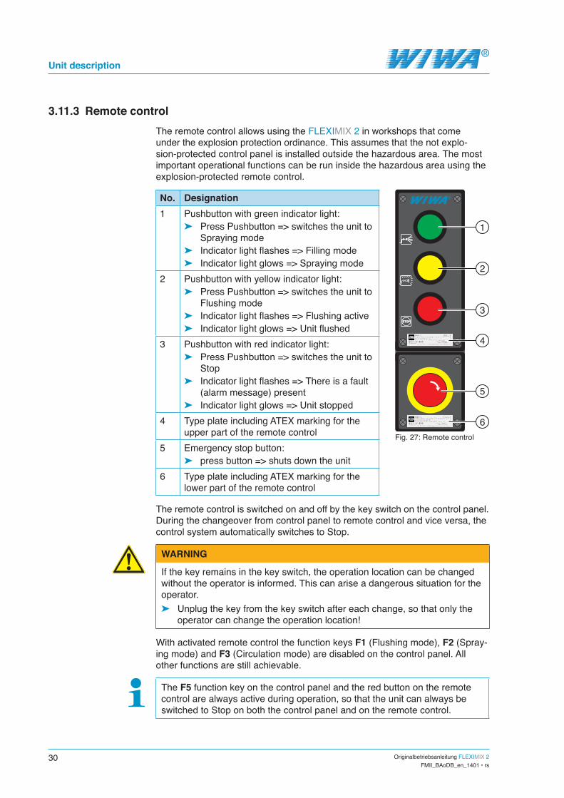
3.11.3 Remote controlThe remote control allows using the FLEXIMIX 2 in workshops that come under the explosion protection ordinance. This assumes that the not explo-sion-protected control panel is installed outside the hazardous area. The most important operational functions can be run inside the hazardous area using the explosion-protected remote control.
No. Designation1 Pushbutton with green indicator light:
➤ Press Pushbutton => switches the unit to Spraying mode
➤ Indicator light flashes => Filling mode ➤ Indicator light glows => Spraying mode
2 Pushbutton with yellow indicator light: ➤ Press Pushbutton => switches the unit to
Flushing mode ➤ Indicator light flashes => Flushing active ➤ Indicator light glows => Unit flushed
3 Pushbutton with red indicator light: ➤ Press Pushbutton => switches the unit to
Stop ➤ Indicator light flashes => There is a fault
(alarm message) present ➤ Indicator light glows => Unit stopped
4 Type plate including ATEX marking for the upper part of the remote control
5 Emergency stop button: ➤ press button => shuts down the unit
6 Type plate including ATEX marking for the lower part of the remote control
Fig. 27: Remote control
STOP
1
2
3
5
4
6
The remote control is switched on and off by the key switch on the control panel. During the changeover from control panel to remote control and vice versa, the control system automatically switches to Stop.
WARNING
If the key remains in the key switch, the operation location can be changed without the operator is informed. This can arise a dangerous situation for the operator.
➤ Unplug the key from the key switch after each change, so that only the operator can change the operation location!
With activated remote control the function keys F1 (Flushing mode), F2 (Spray-ing mode) and F3 (Circulation mode) are disabled on the control panel. All other functions are still achievable.
The F5 function key on the control panel and the red button on the remote control are always active during operation, so that the unit can always be switched to Stop on both the control panel and on the remote control.
Originalbetriebsanleitung FLEXIMIX 2 31FMII_BAoDB_en_1401 • rs
Unit description
3.11.4 USB interfaceThe USB interface enables:
➤ downloading the data stored in the control system (volumes, alarms, etc.) on a USB stick,
➤ updating the software for the control system.If your FLEXIMIX 2 is equipped with a USB interface, it is located on the control panel left below the control module. It is marked with the USB symbol.
Fig. 28: USB interface
STOP
RESET
USB POWER
www.wiwa.de
I0I0
3.11.5 Volumetric measurement valvesThe volumetric measurement valves are located on the mixing unit. By default, the two components are successively filled during control measurement or volumetric measurement process via one outlet (the spray gun). In contrast, the two volumetric measurement valves enable separate filling of the A and B component.The valves are only opened for control measurement or volumetric measurement and remain closed otherwise:
➤ turn counterclockwise to open, ➤ turn clockwise to close. open close
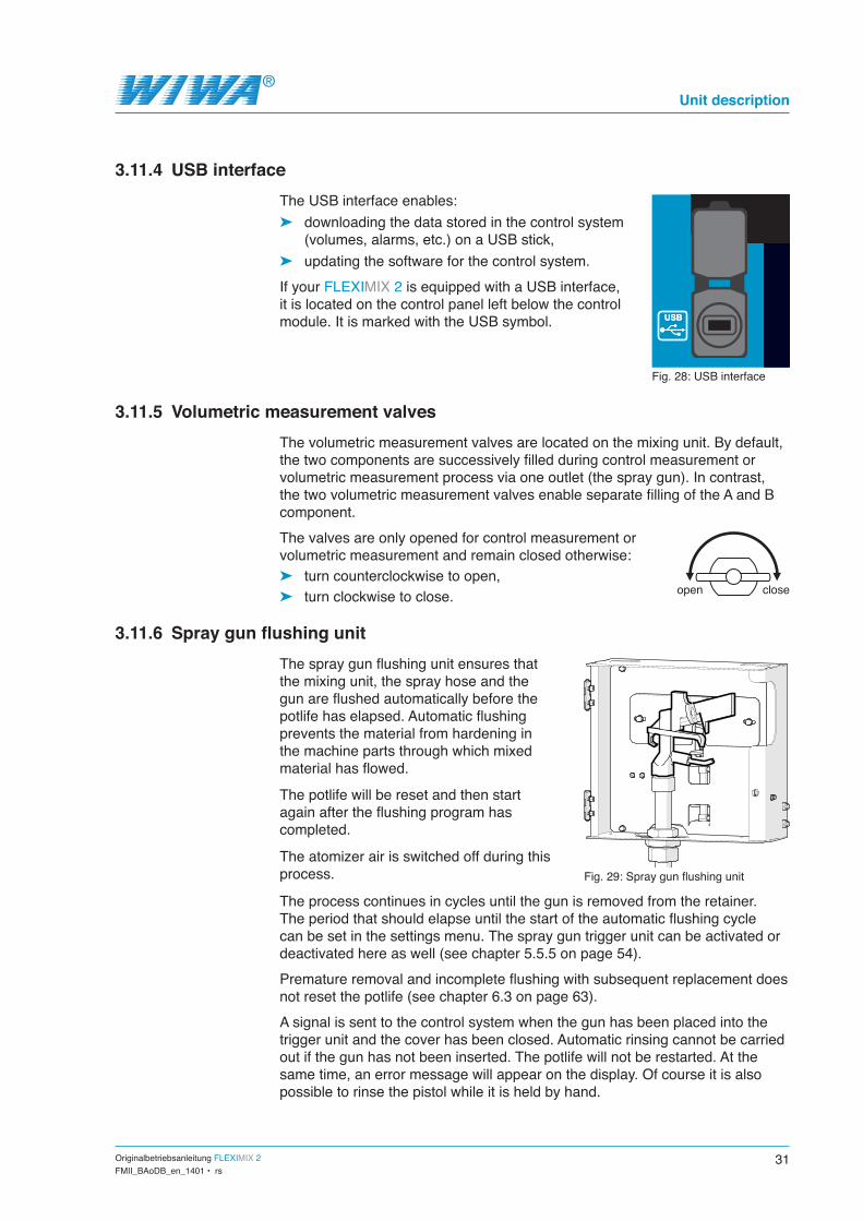
3.11.6 Spray gun flushing unitThe spray gun flushing unit ensures that the mixing unit, the spray hose and the gun are flushed automatically before the potlife has elapsed. Automatic flushing prevents the material from hardening in the machine parts through which mixed material has flowed.
The potlife will be reset and then start again after the flushing program has completed.
The atomizer air is switched off during this process. Fig. 29: Spray gun flushing unit
The process continues in cycles until the gun is removed from the retainer. The period that should elapse until the start of the automatic flushing cycle can be set in the settings menu. The spray gun trigger unit can be activated or deactivated here as well (see chapter 5.5.5 on page 54).Premature removal and incomplete flushing with subsequent replacement does not reset the potlife (see chapter 6.3 on page 63).A signal is sent to the control system when the gun has been placed into the trigger unit and the cover has been closed. Automatic rinsing cannot be carried out if the gun has not been inserted. The potlife will not be restarted. At the same time, an error message will appear on the display. Of course it is also possible to rinse the pistol while it is held by hand.

32 Originalbetriebsanleitung FLEXIMIX 2FMII_BAoDB_en_1401 • rs
Unit description
Depending on the safety time buffer of the potlife and the length of time exceeded, this may make it necessary to replace the entire machine section from the mixing unit to the gun as it may be difficult or impossible to remove any dried up material from these parts.
3.11.7 Mounting kit for atomizing airWhen using the FLEXIMIX 2 with Air Combi gun the mounting kit for atomizing air supplies the spray gun with atomizing air. It consists mainly of an air pres-sure regulator with gauge located in the compressed air control unit on the control panel (see Fig. 11 on page 23).The air passes through the air regulator and a separate air hose to the atom-izer air connection for the Air Combi gun on the front side of the FLEXIMIX 2 (see Fig. 7 on page 19).
3.11.8 Air flushingThe mixing unit can be optionally equipped with extra air flushing. Another valve is installed in the mixing unit for this purpose and supplied by the existing compressed air.
3.11.9 Mounting kit “Error message”The mounting kit “Error message” includes an acoustic signal (horn) which indicates any malfunctions with a loud continuous sound.The signal can be acknowledged with the illuminated push button on the operating panel (see Fig. 12 on page 23).
3.11.10 AgitatorsThe feed hoppers can optionally be fitted with pneumatic agitators which are supplied with compressed air from the air maintenance unit. The agitators ensure uniform temperature and consistency of the material by feeding it from the wall to the centre of the feed hopper rather than stirring it up from the bottom.
Fig. 30: Agitator in the feed hopper
Observe and follow the separate operating manual for the agitators.

Originalbetriebsanleitung FLEXIMIX 2 33FMII_BAoDB_en_1401 • rs
Transportation, installation and assembly
4 Transportation, installation and assemblyThe unit left the factory in flawless condition and was appropriately packed for transportation.
Check the unit on receipt for any damage in transit and for completeness.
4.1 TransportationPlease follow these notes when transporting the unit:
➤ Ensure sufficient load bearing capacity of lifting gear and lifting tackle when loading the unit. You will find the dimensions and weights of the unit on the machine card.
➤ The unit must only be lifted by the lifting and lashing points provided for this purpose.
➤ Make sure that the fork tines are long enough when using a forklift truck. You must guide the fork tines through the two opposite forklift lifting points on the rack.
➤ When transporting using a fork lift truck, have the forks as far apart as pos-sible to minimize the overturning moment.
➤ Caution danger of tipping! Ensure even load distribution to secure the sys-tem against tipping over.
➤ Do not transport any other objects (e.g. material drums) while lifting or loading the unit.
➤ Never stand under suspended loads or inside the loading area. This poses a life hazard!
➤ Secure the load on the transport vehicle against slipping and falling off.If the unit was already operated, please observe the following:
➤ Disconnect the entire unit power supply – even for short transportation distances.
➤ Empty the unit before transportation – fluid residues may escape during transportation despite this measure.
➤ Remove all loose parts (e.g. tools) from the unit. ➤ Assemble the parts or fittings dismantled for transport purposes before start
up and in compliance with the intended use of the unit.
4.2 Installation locationBy standard the unit is intended for installation outside explosion protected areas. Only units of explosion protected design may be installed inside EX- environments.The ambient temperature has to be between 0 °C and 40 °C.The unit can be installed inside and outside spray booths. However, outdoor installation should be preferred in order to avoid contamination.

34 Originalbetriebsanleitung FLEXIMIX 2FMII_BAoDB_en_1401 • rs
Transportation, installation and assembly
WARNING
If the unit is used outside during a thunderstorm, a lightning strike can cause a life-threatening situation for the operating personnel.
➤ Do not operate a unit out of doors during a thunderstorm! ➤ The unit owner must ensure that the unit is equipped with suitable light-
ning protection equipment.
As a standard, the FLEXIMIX 2 is equipped with 4 adjustable machine feet (see Fig. 31). Alternatively the machine can be equipped with 4 swivel rollers (see Fig. 32).
Fig. 31: Machine foot Fig. 32: Swivel roller
Set up the unit horizontally on a foundation that is flat, firm and free from vibrations. The unit must not be tipped or on an incline. Ensure that all the operating elements and safety features are easy to reach.
Safety measures at the place of installation: ➤ This unit requires a solid base and suffi-
cient free space for safe operation. ➤ If the FLEXIMIX 2 is equipped with swivel
rollers, the machine has to be locked in its place of installation to prevent unwanted movements. To do this, engage the wheel brakes on the swivel rollers.
➤ Always keep the working area, especially all walkways and standing areas, clean and tidy. Immediately remove any spilled material and solvents immediately.
➤ Always ensure adequate ventilation at the work place to avoid damage to health and material objects.
Fig. 33: Wheel brake
➤ Always observe the processing instructions issued by the material manu-facturers.
➤ Even though there are no legal directives for low-mist Airless spraying methods, all hazardous solvent vapours and paint particles should be extracted.
➤ Protect objects adjacent to the spraying object against possible damage caused by the material mist.

Originalbetriebsanleitung FLEXIMIX 2 35FMII_BAoDB_en_1401 • rs
Transportation, installation and assembly
4.3 Assembly
WARNING
If assembly work is carried out by people who have not been trained for this work, you endanger yourself and other people and impair the safety and reliability of the unit.
➤ Electrical components must only be mounted by trained time-served electricians – with all the other components, e.g. the spray hose and the spray gun being assembled by trained personnel only.
4.3.1 Assembling hose packageWhen using an external mixing unit, the hose package is used to connect the external mixing unit to the intermediate piece.
WARNING
If the hose package couplings are subjected to tensile load, these assem-blies may be torn out. Material escaping under high pressure can cause injuries and material damage.
➤ If tensile loads on the hose package couplings are to be expected (e.g. by positioning the mixing unit), a strain relief is required.
If the hose package is too tightly bent, hoses may buckle inside the hose package.
➤ The minimum bending radius of 30 cm must not be fallen short of!
Fig. 34: Connections on the intermediate piece
521
3
4
41
3
2
5Fig. 35: Connections on the mixing unit
Nr. Connection1 A component flow2 A component return flow3 Flushing4 B component flow5 B component return flow

36 Originalbetriebsanleitung FLEXIMIX 2FMII_BAoDB_en_1401 • rs
Transportation, installation and assembly
4.3.2 Assembling spray hose and spray gun
WARNING
Components that do not comply with the maximum permitted operating pres-sure of the unit can burst and cause serious injury.
➤ Check the maximum permitted operating pressure of the material hose and the spray gun before assembly. It must be greater than or equal to the maximum operating pressure of the unit as specified on the type plate.
Fit the spray hose to the material outlet of the static mixer:
Fig. 36: Assembly of the spray hose at the standard mixing unit (left) or at the external mixing unit (right)
Connect the spray hose to the spray gun as described in the operating man-ual for the spray gun used.
4.3.3 Grounding the unitUpon delivery the ground cable is already connected to the unit. To ground the unit, connect the clamp of the ground cable to an electrically conductive object.
4.3.4 Inserting the filter elements into the high pressure filtersInsert the filter elements suitable for the material to be used into the high pres-sure filters. You can find more information in section 7.5.2 on page 71.

Originalbetriebsanleitung FLEXIMIX 2 37FMII_BAoDB_en_1401 • rs
Transportation, installation and assembly
4.3.5 Connecting compressed air supply and electric power supply
The compressor capacity must match the air requirements of the unit and the diameters of the air supply hoses must match the connections such that an adequate air supply is ensured.
Operation with contaminated or moist compressed air causes damage to the unit's pneumatic system.
➤ Use only dry dust- and oil-free air!
Fig. 37: Compressed air connection at the PHOENIX (left) or PROFESSIONAL and HERKULES (right)
1. Make sure that ➤ all air pressure regulators have been regulated completely down, ➤ the master switch is set to "0".
2. Connect the compressed air line to the compressed air connection at the maintenance unit.
3. Plug the mains plug into a suitable electric power supply. The power supply data can be found on the type plate of the control box.
The FLEXIMIX 2 with 230 V rated voltage can be used in a voltage range of 100 V to 230 V.

38 Originalbetriebsanleitung FLEXIMIX 2FMII_BAoDB_en_1401 • rs
Control module
5 Control module
5.1 Controls
Fig. 38: Control elements on the control module
OMRON
RUN
F1
F2
F3
F4
F5
1
2
The Fig. 38 shows the control module with a small touch-screen and 5 function keys. Alternatively, a control module with a large touch screen and 6 function keys can be used, in which the F6 key has no function. The operation of both control modules is the same.All control functions may be selected from the touchscreen with the five func-tion keys (1) and the buttons displayed in the various menu windows (2).The control system is divided into two areas – the operating area accessible to all and the password-protected settings area.
5.2 Starting the unitWhen the unit is switched on, the touchscreen first displays the Welcome screen. After a few seconds it continues automatically to the Overview. The Overview is the basic display in the control system.
Fig. 39: Welcome screen Fig. 40: Overview

Originalbetriebsanleitung FLEXIMIX 2 39FMII_BAoDB_en_1401 • rs
Control module
5.3 Menu structure
WIWAStart screen
Info42
Day counter6-1020
Day counter1-517
USB-Datalog48
Alarm history46
Setup 102
Language41
Set filllevel 1-3
16
Change recipe No / Yes
49
Flush before-No / Yes
6
Recipeselection
32
Set filllevel 4-6
33
Set filllevel 7-9
34
Set filllevel 10
35
Overview14
automatic
Setup 205
Recipemanagement
31
Valvemanagement
04
Set date/time39
Flushparameters
3
Manualcontrol valve
18
Setup fill 108
Fill level 1-313
Setup fill 215
Fill level 4-636
Fill level 7-937
Fill level 1038
Vol. measure-ment A
measuring cup23
Volumetricmeasurement
component10
Vol. measure-ment B
measuring cup26
Vol. measure-ment B
measured vol.27
Vol. measure-ment A
measured vol.24
Ope
ratio
n se
ctio
n
Setu
p se
ctio
n
Main menu01
Controlmeasurement
07
Fill measu-ring cup
44
Mixing ratio50
Alarms12

40 Originalbetriebsanleitung FLEXIMIX 2FMII_BAoDB_en_1401 • rs
Control module
5.3.1 NavigationThe individual menu windows can be selected using the corresponding buttons in the overview, the main menu or the settings menu. In addition, the following standard functions are available for navigation within the menu structure:
Home: Return to the basic display (Overview)
Level up: switch to the next higher menu level
Continue: scroll forward on the same menu level
Back: scroll on the same menu level back
5.3.2 Symbolism of the buttonsThe buttons in the control system are indicated by the following symbols:
Symbol Meaning
Alarm
Alarm history
Volumetric measurement
Date and time
Fill level alarm
Fill level parameter
Reset fill level
Main menu
Home
Information
Details relating to mixing ratio and volume
Control measurement
Symbol Meaning
Recipe selection
Recipe management
SERVICE
Service
SETUP
Setup
Setup fill
Language selection
Pot life
USB
USB
Manual valve control
Valve management
Counter

Originalbetriebsanleitung FLEXIMIX 2 41FMII_BAoDB_en_1401 • rs
Control module
5.4 Operation areaAll operating functions can be run using the function keys F1 - F5 and the but-tons in the overview and those of the Main menu.
5.4.1 Function keys and overview
Fig. 41: Function keys and overview
F1
F2
F3
F4
F5
5
2
9
14
15
16
17
18
4
6
1110
3
12
8
7
13
1
No. Display / function1 Number of the menu window2 Name of recipe currently selected3 Status display4 Displays the operating mode5 Displays the nominal mixing ratio according to the recipe selected 6 Displays the pot life configured in the recipe7 Progress bar for spray hose filling8 Progress bar for pot life already passed9 Display of the levels in the material containers of the A component (blue
bar) and B component (red bar) currently being used10 Reset fill levels11 Switch to Recipe selection12 Display information relating to mixing ratio and volume13 Switch to Main menu14 Switch to flushing mode15 Switch to spray mode16 Switch to circulation mode17 Reset key for acknowledging alarm messages18 Switch to Stop

42 Originalbetriebsanleitung FLEXIMIX 2FMII_BAoDB_en_1401 • rs
Control module
5.4.2 Main menu
Fig. 42: Main menu
2 3 41
5
6
8
7
No. Display / function1 Display current alarm message (if present)2 Run control measurement3 USB datalog4 Language selection5 Display alarm history6 Switch to Setup menu (password required)7 Display day and batch counter8 Show display and control system software versions
5.4.3 Status displayThe control system uses the status display to indicate selected operating states. It is shown in the title bar of all menu windows. The following icons may be seen here:
There is a fault (alarm message) present.
The unit is being flushed.
The pot life has expired.
A material container has been emptied down to the minimum level.
The relevant status displays will be shown flashing in a cycle if there a number of these operating states are present simultaneously (e.g. Fault and Pot life expired).

Originalbetriebsanleitung FLEXIMIX 2 43FMII_BAoDB_en_1401 • rs
Control module
5.4.4 Displaying the operating modeThe operating mode currently selected is indicated in all menu windows by the icon to the far right of the title bar. The following icons may be seen here:
Filling
Spraying
Flushing
Circulating
Volumetric measurement
Stop
5.4.5 Spraying mode (F2)Press the function key F 2 to switch the control system to Spraying mode. The metering valves are opened in spraying mode. The two components of the material to be processed are pumped through the mixing block and the static mixer to the spray gun and mixed together as they pass through the static mixer. The touchscreen displays the overview during spraying operation.
Observe the operating mode display. When spraying operation has started, the operating mode initially displays Filling and then changes to Spraying as soon as the spray hose is filled with material. Only then the unit is ready for operation.
An interruption of spraying mode during which the unit is not flushed will activate pot life monitoring – this can be seen by the black progress bar in the overview. Pot life is the period in which the mixed material can be processed from the time of it being mixed until the material increasingly cures. Pot life monitoring is intended to prevent the mixed material curing in the unit. You will see an appropriate alarm message when the pot life has expired. In this case you must immediately either flush the unit or continue spraying.
5.4.6 Flushing mode (F1)Press the function key F 1 to switch the control system to Flushing mode. The metering valves are closed in flushing mode. The flushing agent is depend-ing on the position of the flushing valves (standard mixing unit) or the flushing ball valves (external mixing unit) pumped through the A and / or B component side of the mixing unit and the static mixer to the spray gun. The purpose of flushing is to flush the mixed material out of the unit before it cures during an interruption in spraying operations.
F2
F1

44 Originalbetriebsanleitung FLEXIMIX 2FMII_BAoDB_en_1401 • rs
Control module
During automatic flushing operation, the touchscreen shows the steps and the current status of the background flushing program. A flushing program may comprise up to eight steps that are executed automatically. The cur-rent volume is displayed all the time a step is running. The volume indicator then goes out. Steps that have already been com-pleted are indicated with a green spot. Fig. 43: Display in automatic flushing operation
The green background Active icon is shown all the time the flushing program is running. The Flushed icon, also with a green background, appears as soon as the flushing program has run to completion.
5.4.7 Circulation mode (F3)In circulation mode, the metering pumps transport the material to be sprayed out of the containers and pump the two components separately into the contain-ers – no mixing occurs. The purpose of circulation is to
➤ fill the unit with material to be sprayed, ➤ vent the unit, ➤ to warm the material to be sprayed uniformly where material heaters are in
use.For the circulation operation, the control system is only relevant if the unit is equipped with an external mixing unit. If you are working with a standard mixing unit, open the return ball valves at the mixing unit to switch the unit into the circulation operation.For units with an external mixing unit, press the function key F 3 to switch the control system to Circulation mode. The touchscreen shows the compo-nent selection and the current status during circulation operation monitored by the system control. You can select the component(s) to be circulated through the unit using the A and B buttons.You can select the two components individually or together. The com-ponents selected are given a green marker. Fig. 44: Display in circulation mode
The green background Active icon is shown all the time circulation is running.
5.4.8 Unit stop (F5)Press the function key F 5 to switch the control system to Stop. The metering valves and the air supply to the metering pumps are closed for a unit stop. The touch screen displays the Overview. The operating mode display shows Stop.
F3
F5

Originalbetriebsanleitung FLEXIMIX 2 45FMII_BAoDB_en_1401 • rs
Control module
5.4.9 Fill level indicationContainer monitoring makes it possible to guarantee a constant supply of ma-terial and hence to prevent the unit being shut down because the material con-tainers have run dry. This assumes that the material containers are swapped or completely filled on every update and that the filling levels are reset to the maximum level.Press the button in the Overview shown on the left to reset the filling levels to the maximum level. The first Set fill level window will then be opened (material containers for valves V1-V3).
Fig. 45: Fill level indication of valves V1-V3 Fig. 46: Fill level indication of valves V4-V6
As the system control monitors the fill levels of up to 10 material containers, but can only show a maximum of 3 filling levels per window, the display is distributed across a number of windows. Use the arrow buttons ( and ) to browse forwards and backwards between the various windows. The volume unit preset in the system control is displayed between these buttons – liters (l.) or U.S. gallons (gal.). The fill levels are shown both as a value in liters or gallons and graphically as a bar. The level bars of the components used in the current recipe are blue (A) and red (B), all the other black. Set the filling level back to the maximum level using the Set button when a material container has been swapped or completely filled.
5.4.10 Recipe selectionUp to 10 different mixing settings can be stored as recipes and recalled in reci-pe selection with just a few button presses. Press the button in the Overview shown on the left to open Recipe selection. You will then see a confirmation prompt to decide whether you really do wish to change the recipe. If you confirm with yes, you then see the question asking whether you wish to flush before changing the recipe.
Fig. 47: Confirmation prompt 2Fig. 48: Confirmation prompt 1
46 Originalbetriebsanleitung FLEXIMIX 2FMII_BAoDB_en_1401 • rs
Control module
You must flush the unit for each change of recipe to prevent reactions between materials!
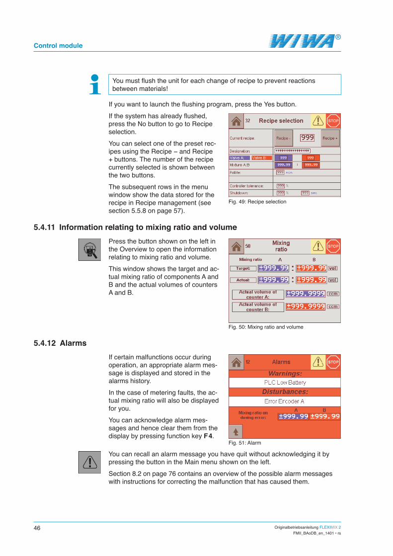
If you want to launch the flushing program, press the Yes button.If the system has already flushed, press the No button to go to Recipe selection.You can select one of the preset rec-ipes using the Recipe − and Recipe + buttons. The number of the recipe currently selected is shown between the two buttons. The subsequent rows in the menu window show the data stored for the recipe in Recipe management (see section 5.5.8 on page 57).
Fig. 49: Recipe selection
5.4.11 Information relating to mixing ratio and volume Press the button shown on the left in the Overview to open the information relating to mixing ratio and volume.This window shows the target and ac-tual mixing ratio of components A and B and the actual volumes of counters A and B.
Fig. 50: Mixing ratio and volume
5.4.12 AlarmsIf certain malfunctions occur during operation, an appropriate alarm mes-sage is displayed and stored in the alarms history.In the case of metering faults, the ac-tual mixing ratio will also be displayed for you. You can acknowledge alarm mes-sages and hence clear them from the display by pressing function key F 4.
Fig. 51: Alarm
You can recall an alarm message you have quit without acknowledging it by pressing the button in the Main menu shown on the left.Section 8.2 on page 76 contains an overview of the possible alarm messages with instructions for correcting the malfunction that has caused them.

Originalbetriebsanleitung FLEXIMIX 2 47FMII_BAoDB_en_1401 • rs
Control module
5.4.13 Control measurementFor the purposes of a control measurement, a predefined measured volume of component A and the corresponding volume according to the mixing ratio of component B are fed separately and dispensed through the spray gun into measuring cups. The purpose of the control measurement
➤ is to check the mixing ratio, ➤ and to check the metering pumps and metering valves for correct operation.
To perform a control measurement, the unit must be filled with processing material and vented.
1. Make sure that all air pressure regulators for the metering pumps have been fully regulated down and the compressed air shut-off valves are opend on the metering pumps that deliver the materials used in the current recipe.
2. Press the button in the Main menu shown on the left. 3. Then press the A+B button on the
component selection screen then displayed.
4. Adjust the air inlet pressure for the metering pumps up to 3,0-3,5 bar.
5. Unlock and operate the spray gun.
The unit delivers the A component at first and after a break of about 10 seconds the B component. The filled volumes are counted up in the display during the control mea-surement.6. Close and secure the spray gun
again once the filling process is finished.
7. Set the air inlet pressure for the metering pumps right down to zero.
Fig. 52: Component selection
Fig. 53: Display during control measurement
8. Wait a few minutes to allow the entrained air to escape from the material in the measuring cups (particularly with more viscous materials).
9. Check ➤ whether the volumes indicated match the actual quantities, ➤ whether the quantities of the two components are correct for the mixing ratio specified in the recipe.
If this is not the case, a volumetric measurement must be performed for the A- and B-component metering pumps used in the current recipe (see section 5.5.2).

48 Originalbetriebsanleitung FLEXIMIX 2FMII_BAoDB_en_1401 • rs
Control module
5.4.14 USB datalogThe data stored in the system control unit (volumes, alarm messages etc.) can be downloaded to a USB stick from the USB datalog.To run a USB datalog, plug a USB stick into the USB port on the control panel and press the button in the Main menu shown on the left.Depending on the amount of data, the USB datalog can take up to 40 minutes. Fig. 54: USB datalog
5.4.15 Language selectionPress the button in the Main menu shown on the left to open the lan-guage selection. The language used for the control system menus can be configured in the language selection. Depending on the region one of the 3 language packages “East”, “North” or “West + South” is installed. You can see from the flag icons what languag-es are available in the respective language package. Press the appro-priate flag icon to select a language. Fig. 55: Language package “East”
Fig. 56: Language package “North” Fig. 57: Language package “West + South”
5.4.16 Alarm historyPress the button in the Main menu shown on the left to have the alarm history displayed. The alarm history saves up to 200 alarm messages with date and time. Once this storage limit is reached, the oldest alarm message is deleted from the alarm history each time a new message is added.Faults can be diagnosed and traced more easily using the alarm history. Fig. 58: Alarm history

Originalbetriebsanleitung FLEXIMIX 2 49FMII_BAoDB_en_1401 • rs
Control module
The service engineer can also read off later which faults occurred when and how frequently.Use the scroll bar on the right-hand edge of the window to navigate through the alarm history.
5.4.17 Day and batch countersThe day and batch counters record the consumption through the various valves per day and batch. Press the button in the Main menu shown on the left to have these counters displayed.
Fig. 59: Counters for valves 1-5 Fig. 60: Counters for valves 6-10
The day and batch counters can be reset to 0 with the reset buttons. This makes it possible to separate the various jobs from each other.The VOC column shows the consumptions of volatile organic compounds (VOC). This is also reset to 0 when a day or batch counter is reset. Use the arrow buttons ( and ) to browse forwards and backwards between these two menu windows. The volume unit preset in the system control is dis-played between these buttons – liters (l.) or U.S. gallons (gal.).
5.4.18 InformationPress the button in the Main menu shown on the left to open the informa-tion.This window displays the software versions of the display and the pro-grammable logic controller (PLC).
Fig. 61: Information

50 Originalbetriebsanleitung FLEXIMIX 2FMII_BAoDB_en_1401 • rs
Control module
5.5 SetupAll the important parameters for set-ting up the system control are stored in the Setup menu. For setting up the system control must be switched to Stop. You will see an appropriate note if you try to open the Setup menu from another operating mode.Please note that this menu is pass-word protected and therefore only accessible to authorised persons. The relevant persons will have the password. Please contact WIWA should the password have been lost.Press the button in the Main menu shown on the left to open the Setup menu. You will then see the password prompt. The first page of the Setup menu will open once the password has been entered.
Fig. 62: Note concerning the operating mode
Fig. 63: Password prompt
Fig. 64: Setup menu part 1
1
2
3
4
5
6
7
Fig. 65: Setup menu part 2
9 108
5
Use the arrow buttons ( and ) to browse forwards and backwards between these two menu windows.
No. Function1 Volumetric measurement2 Set up flushing program3 Set hose volume and mixer type4 Configure filling level monitoring5 Log out from the Setup menu and return to the Main menu6 Set date and time 7 Manual valve control8 Set up valve management9 Set up recipes10 Change to the Service level (accessible only to WIWA Customer Service)

Originalbetriebsanleitung FLEXIMIX 2 51FMII_BAoDB_en_1401 • rs
Control module
5.5.1 KeypadsUnlike in the operating area, the menu windows for the setup area include input fields in addition to the display and selection fields. Input fields have a yellow back-ground, with a few exceptions.Press the input field concerned if you wish to enter some information. The relevant keypad will then be displayed according to the input field concerned. To enter values press the characters from the character set shown on the keypad in sequence.
Fig. 66: Example of a keypad
Button FunctionHome Moves the cursor to the leftmost positionEnd Moves the cursor to the rightmost positionSP Delete character to the rightBS Delete character to the left>> Move cursor to the right<< Move cursor to the leftShift Select the top character shown on the key (capitals)ENT Confirm input (Enter)CLR Clear everything
5.5.2 Volumetric measurementAs the output of the metering pumps declines as wear increases, the K factors (number of measuring pulses of the volume counter per litre) has to be reca-librated from time to time by volumetric measurement. In this way, the most precise possible mixing ratio can be ensured over the long term.
To perform a volumetric measurement of a metering pump, it must be filled with processing material and vented.
1. Make sure that all air pressure regulators for the metering pumps have been fully regulated down and only the compressed air shut-off valve on the metering pump you want to measure is opend.
2. Press the button in the Setup menu shown on the left.
3. From the volumetric measurement menu then shown, select:
➤ A to measure the metering pump for the A component currently selected.
➤ B to measure the metering pump for the B component currently selected.
Fig. 67: Component selection

52 Originalbetriebsanleitung FLEXIMIX 2FMII_BAoDB_en_1401 • rs
Control module
4. Adjust the air inlet pressure for the metering pumps up to 3,0-3,5 bar.5. When prompted by the control
system, pour a specified quantity of material via the spray gun into a measuring cup (generally 1000 cm³) and acknowledge this step by pressing .
6. Close and secure the spray gun again once the filling process is finished.
7. Set the air inlet pressure for the metering pumps right down to zero.
8. Wait a few minutes to allow the entrained air to escape from the material in the measuring cup (particularly with more viscous materials).
9. Enter the material quantity poured as the measured volume. You can enter the measured vol-ume in cubic centimeters (ccm) or U.S. fluid ounces (fl.oz.).
Fig. 68: Control system prompt
Fig. 69: Measured volume and K factor
The more accurately you work here, the more precise the mixing ratio will be later on!
10. Press the Calculate button to have the new K factor determined by the control system.
11. Save the new settings. You can quit the menu by pressing the Finished button.
5.5.3 Flush parametersBy the definition of flush parameters you can set a flushing program up to eight sequential steps that are worked through automatically. This feature requires automatic flushing valves. So it can only be used if the FLEXIMIX 2 is equipped with a standard mixing unit. For FLEXIMIX 2 with external mixing unit you must control the flushing process manually using the flushing ball valves.The flushing volumes and the se-quence of steps should be agreed with the materials supplier and set accordingly. Certain components could be incompatible. Changes can be made later at any time. Press the button in the Setup menu shown on the left to open the Flush parameters input window. You define the flush parameters step by step. To do this first enter the vol- Fig. 70: Flush parameters
ume or duration of the step concerned in seconds or cm³.

Originalbetriebsanleitung FLEXIMIX 2 53FMII_BAoDB_en_1401 • rs
Control module
Clicking the button after the input field switches the unit between sec and cm³.
If the unit is not equipped with flow rate measuring cells or a flush pump with shaft encoder or stroke sensor, the flushing volume can not be detected. In this case, only a time target can be specified for each step of the flushing program.
Then press the Setup button to open the action selection.Use the buttons here to determine what ac-tion is to be executed in the step concerned. The Air and Break actions can only be acti-vated in the low pressure pump if a valve for air flushing is present.Once you have defined all the steps in the flush program, you must specify how many times this sequence is to be repeated.
Fig. 71: Action selection
5.5.4 Manual valve controlPress the button in the Setup menu shown on the left to open the Manual valve control window.The various valves involved in the function check can be controlled from here by pressing the relevant button. The button for the valve currently open has a green background. Only one valve can be opened at a time. An open valve is automatically closed when another valve is selected. This prevents material from penetrating another valve which could trigger malfunctions.
Fig. 72: Manual valve control
Label Which valve?Main valve Shut-off valve for the compressed air inletV1 - V10 Metering valves 1-10Flush A Flushing valve for A component sideFlush B Flushing valve for B component sideFlush Air Air flushing valvePressure Valve for switching between flushing pressure / spraying pressureAtomizer Atomizer air valveSpray gun Spray gun
When checking function, always open the valve first and then fill it by slowly building up the pressure. This allows potential leaks to be detected quickly and prevents pressure surges.The flush valves should always be used at the start and end of the function check on a material valve to prevent a chemical reaction between any possible material component residues.

54 Originalbetriebsanleitung FLEXIMIX 2FMII_BAoDB_en_1401 • rs
Control module
5.5.5 Filling parameters (Setup fill)Press the button in the Setup menu shown on the left to open the input window for entering the filling parameters. In this input window, enter:
➤ the volume of the spray hose under “Spray hose volume”.The formula for calculating the volume of hoses and a table of volumes for common hoses can be found in chapter 10 on page 79.“Fill” will be shown on the display until this volume of material has left the spray gun after the start of spraying operation. The aim is to Fig. 73: Filling parameters part 1prevent material that is mixed incorrectly or not mixed at all being applied.
➤ The minimum volume that must have left the spray gun after an interrup-tion in spray operation without flushing before pot life monitoring is reset in “Volume for potlife reset”. The complete volume of the line system must be taken into account here (static mixer + hose + safety margin) as otherwise the full volume of old material will not be expelled.
➤ The mixing tolerance, beyond which the system should switch off automati-cally during filling in “Mix ratio limit when filling”.
➤ The output of the flushing pump in “Volume flushing pump double stroke". You will find this value on the flushing pump type plate.
➤ The period that should pass until the Atomizer air malfunction fault mes-sage will be displayed if the A component does not flow when the air flow is present in “Delay of atomizer air sensor” (only for FLEXIMIX 1).
Three option buttons follow the input fields (enabled options have a green background):
➤ “External mixer”: This option should be switched ➤ On, if you are using an external mixer, ➤ Off, if you are using a mixer on rack.
The system control must be adjusted to the mixer type used as, in Circula-tion mode, the metering valves:
➤ must be closed if the mixer is on the rack (Circulation on the "short route" from the mixing unit back to the material container) and
➤ must be open for an external mixer (Circulation on the "long route" from the mixer unit through the hose package back to the material container).
➤ “Flush atomizer air”: Switch the atomizer air off when the gun is connect-ed to the trigger device, as otherwise the cleaning agent is atomized and escapes into the environment.
➤ “Atomizer air sensor”: The atomizer air sensor monitors the air flow of the atomizer air in spraying mode (see also “Delay of atomizer air sensor”).

Originalbetriebsanleitung FLEXIMIX 2 55FMII_BAoDB_en_1401 • rs
Control module
Use the arrow button to access another window in which you can make the following entries:
➤ “Delay start of flushing via spray gun”: Period, which is available to the user to place the gun into the gun triggering device after a pot life alarm. The following condi-tions must be met for the opera-tion of the triggering device:
➤ The Trigger device option but-ton must be showing Auto.
➤ The spray gun must be insert-ed in the triggering device. Fig. 74: Filling parameters part 2
➤ “Factor A of flushing valve”: K factor for the A component flushing valve. The K factor for the flushing valves cannot be determined by volumetric measurement. You must therefore either take the information from the tech-nical specifications for the measuring cell or take the K factor of a metering valve determined already by volumetric measurement (see section 5.5.7 on page 56).
➤ “Factor B of flushing valve”: K factor for the B component flushing valve (See Factor for A flushing valve).
➤ “Flush pump VOC share”: Enter the solvent component of the flushing agent as a percentage (%). The volume contributes to the VOC counter and is added there (see section 5.4.17 on page 49).
Four option buttons follow the input fields: ➤ “Volume unit”: This option should be switched to
➤ l., if you want to use liters as volume unit, ➤ gall., if you want to use U.S. gallons as volume unit.
➤ “Select stroke sensor flushing pump”: This option should be switched ➤ ON, if the flushing volume is to be determined by the stroke sensor on the flushing pump,
➤ OFF, if the flushing volume is to be determined by the gear flow meters. ➤ “Gun trigger device”: This option should be switched to
➤ AUTO, if the spray gun is to be flushed automatically by the trigger device,
➤ MANUAL, if no trigger device is fitted or if its automatic function is not to be used.
➤ “Fill spray gun”: This option should be switched to ➤ AUTO, if the spray gun is to be filled with material for spraying automatically as soon as the spray gun is plugged into the trigger device, spraying mode is selected and the Trigger device option button is set to AUTO.
➤ MANUAL, if no trigger device is fitted or if its automatic function is not to be used.

56 Originalbetriebsanleitung FLEXIMIX 2FMII_BAoDB_en_1401 • rs
Control module
5.5.6 Filling level monitoringFilling level monitoring makes it possible to guarantee a constant supply of ma-terial and hence to prevent the system being shut down because the material containers have run dry. The prerequisite for this is that the maximum and mini-mum filling levels of the material containers are stored in the control system.
Filling level monitoring is a purely computational process. It does not replace measurement by level sensors.
Press the button in the Setup menu shown on the left to open the input window for maximum and minimum filling levels.
Fig. 75: Filling level monitoring for valves V1-V3 Fig. 76: Filling level monitoring for valves V4-V6
As the system control monitors the fill levels of up to 10 material containers, but can only show a maximum of 3 filling levels per window, the display is distribut-ed across a number of windows. Use the arrow buttons ( and ) to browse forwards and backwards between the various menu windows. The volume unit preset in the system control is displayed between these buttons – liters (l.) or U.S. gallons (gal.).The Actual line shows the current fill levels of the containers concerned.Enter for all material containers:
➤ Min: The minimum filling level at which a message should appear in the display. In volumetric measurement mode, the unit is automatically switched off at this level.
➤ Cont: The size of the container you are using.Press the Set button after entering the minimum filling level and container size to save your input for each of the containers.
5.5.7 Valve managementThe control system can manage up to 10 valve/pump combinations. A valve/pump combination comprises the metering valve and the metering pump. The data for the valve/pump combinations used in the unit is re-corded in Valve management. Press the button in the Setup menu shown on the left to open the Valve management input window.
Fig. 77: Valve management

Originalbetriebsanleitung FLEXIMIX 2 57FMII_BAoDB_en_1401 • rs
Control module
In Valve management, you can enter: ➤ Current valve: Number of the valve/pump combination – this can be se-
lected using the Valve - and Valve + buttons. ➤ Impulses per litre: The output of the metering pump is calculated from the
electrical pulses of the volume counter or shaft encoder using the number of pulses per litre (K factor). This factor is determined from the metering pump output. The K factor has to be recalibrated from time to time by volumetric measurement as the output of a metering pump declines with increasing wear in operation (see section 5.5.2 on page 51).
➤ VOC share: Proportion of solvent in the materials used as a percentage (VOC = Volatile Organic Compounds).
➤ Double stroke error: Minimum duration of an error-free double stroke, at below which a corresponding alarm is to be output (approx. 700 ms).
Press the Save button to save your input.
5.5.8 Recipe management
The data for the valve/pump combination in use on the unit must be recorded in Valve management before you can set up recipes.
Press the button in the Setup menu shown on the left to open the Recipe management input window.Enter the following data to set up a recipe:
➤ Current recipe: Recipe number – this can be selected using the Recipe – and Recipe + buttons. You can create up to 10 different recipes.
➤ Designation: Recipe name. Fig. 78: Recipe management
➤ Valve A: Number of the valve/pump combination through which the A com-ponent used in the recipe will be delivered.
➤ Valve B: Number of the valve/pump combination through which the B com-ponent used in the recipe will be delivered.
➤ Mixture A : B: Desired volumetric mixing ratio between the A and B com-ponent. If the mixing ratio is defined by weights, you have to convert the weights into volumes.
Volume = WeightDensity Weight = Volume . Density
➤ Pot life: Pot life is the period in which the mixed material can be processed from the time of it being mixed until the material increasingly cures.
➤ Controller tolerance: Permissible deviation from the desired mixing ratio. The tolerance range is factory set to ± 3%. If the deviation is greater than the pre-set tolerance, the controller intervenes to correct.

58 Originalbetriebsanleitung FLEXIMIX 2FMII_BAoDB_en_1401 • rs
Control module
➤ Shutdown: In the event that the deviation from the desired mixing ratio is greater than the tolerance, we define an error limit and a period, which exceeding the error limit must continue before the controller outputs an alarm message and shuts down the unit automatically. The error limit for automatic shutdown is factory set to ± 5%, the fault duration to 5 seconds. With these settings, the unit is switched off automatically when the mixing error is greater than ± 5 % and lasts longer than 5 seconds.
Example for the behavior of the control system with the factory settings:
Desired mixing ratio+ 1%+ 2%+ 3%+ 4%+ 5%+ 6%+ 7%
– 1%– 2%– 3%– 4%– 5%– 6%– 7%
Tolerance limit
Shutdown limit
± 0%
Tolerance limit
Shutdown limit
0 5 10 15 20 25 30 Seconds
Deviation
5 sek
Shutdown
Use the Yes/No button in the Enable row to specify whether the recipe is to be released for use in Recipe selection.Press the Save button to save your input.
5.5.9 Date and timePress the button in the Setup menu shown on the left to open the input window for setting the date and time.Here you can set the date (day, month, year) and the time (hour, minute, second) using the 2 buttons (+ and −) for each of these.Examples:
➤ Press the D+ button three times to adjust the date from 14 to 17.
➤ Press the D− button once to ad-just the date from 14 to 13.
Fig. 79: Setting date and time
5.5.10 Software UpdateTo update the control system software, insert a USB stick carrying the new ver-sion of the software into the USB port on the control panel and press the USB Software Update button in the Set date/time input window (see section 5.5.9).

Originalbetriebsanleitung FLEXIMIX 2 59FMII_BAoDB_en_1401 • rs
Operation
6 OperationBefore starting work, check:
5 Are all the safety features present and fully functional (see chapter 2.4 on page 13)?
5 Are all unit components tight? If required, tighten up these connections. 5 Is there enough release agent in the metering pumps (see chapter 7.6.1 on
page 72)?
WARNING
If material pumps run dry, the generated friction heat can cause fire or an explosion.
➤ Always make sure that the material drums do not run dry during opera-tion.
➤ However, should this happen, stop the corresponding pump immediately and feed material.
6.1 Put the unit into operationPrerequisites:
➤ The unit must have been set up correctly and completely assembled. ➤ Do not start commissioning the unit unless you have the specified protec-
tive equipment. For details, refer to chapter 2.5.4 on page 16. ➤ The material to be processed must be available in sufficient quantity. In
addition, you will need two suitable collecting vessels for excess material. These containers are not included in the scope of delivery.
Observe the technical notes of the respective material manufacturer.
During commissioning, check that the unit or its individual components are leak-proof by slowly building up pressure.Overview of the work sequence for commissioning:1. Switch on the unit2. Set up the control system (only during initial commissioning)3. Flush mixing unit and spray gun4. Clean the unit (only during initial commissioning)5. Fill the unit with material to be applied and vent the unit6. Put the material flow heaters into operation (if existing)7. Perform a control measurement

60 Originalbetriebsanleitung FLEXIMIX 2FMII_BAoDB_en_1401 • rs
Operation
6.1.1 Switching on the unit1. Make sure that all air pressure regulators have
been fully regulated back.2. Switch on the unit at the master switch on the
control panel.When the unit is switched on the touchscreen first displays the Welcome screen (see Fig. 39 on page 38). After a few seconds it continues au-tomatically to the Overview (see Fig. 40 on page 38). The Overview is the basic display in system control.
Fig. 80: Switching on the unit
0Off
on
In addition, the shut-off valve for compressed air supply to the metering pumps at the maintenance unit is opened when the unit is switched on.
6.1.2 Setting up the control systemDuring initial commissioning, the parameters for the control system must be adjusted by trained personnel such as:
➤ the valve management, ➤ the recipe management, ➤ the filling parameters, ➤ the flush parameters etc.
For details on this topic, refer to chapter 5.5 on page 50.
6.1.3 Flushing mixing unit and spray gun
The flushing pump should always be ready for use while the unit is being used so that all components coming into contact with the mixed material can be flushed within the pot life specified.
1. Place the suction pipe of the flushing pump into the flushing agent drum.2. Set a pressure of 3-6 bar on the pressure regulator of the flushing pump
depending on the length of the material hoses.3. Press the F 1 function key on the control module to switch the control system
to flushing mode.4. Hold the spray gun into a collection container.5. Unlock the spray gun and trigger it, until the flushing process has completed.6. Close and secure the spray gun.
6.1.4 Cleaning the unitAfter assembly, this unit was factory tested for flawless function by means of a test substance. During initial commissioning you must therefore perform a com-plete cleaning in order to flush out any test medium residues. For details on this topic, refer to chapter 6.5 on page 64.

Originalbetriebsanleitung FLEXIMIX 2 61FMII_BAoDB_en_1401 • rs
Operation
6.1.5 Filling the unit with material to be applied and venting the unit1. Connect the material feed:
➤ For metering pumps with material supply by suction pipes, place the suction pipes into the corresponding material drums with components A and B.
➤ For metering pumps with material supply by feed drums, fill components A and B into the corresponding feed drums and open the stop cocks on the material inlet of the metering pumps (if existing).
➤ For metering pumps with material supply by feed pumps, place the suction pipes on the feed pumps into the corresponding material drums with components A and B and set the air pressure regulators on the feed pumps to a pressure of approximately 3-4 bar.
2. Guide the return flow hoses for components A and B into the corresponding material drums and secure them against accidentally slipping out.
3. Press the F 3 function key on the control module to switch the control system to circulation mode.
The metering pumps are filled with material and vented in circulation mode. This is a prerequisite for complying with the mixing ratio. First fill and vent the metering pump for component A and then do the same for the metering pump for component B.4. Open the compressed air shut-off valve at the air inlet of the A component
metering pump.5. Select component A in the control system Circulate window. 6. Open the return ball valve for the A component at the mixing unit.7. Set the air pressure regulator on the metering pumps so that the A compo-
nent metering pump runs slowly.8. Allow the material to circulate until the material flowing out of the return flow
hose is free of air bubbles.9. Set the air inlet regulator for the metering pumps right down to zero.10. Close the return ball valve for the A component at the mixing unit.11. Close the compressed air shut-off valve at the air inlet of the A component
metering pump.12. Repeat steps 4-11 for B component.
6.1.6 Put the material flow heaters into operation1. Switch on the material flow heaters on the control panel.2. Set the desired material temperature on the temperature regulators of the
material flow heaters.3. Allow the material to circulate until the processing temperature has been
reached.

62 Originalbetriebsanleitung FLEXIMIX 2FMII_BAoDB_en_1401 • rs
Operation
6.1.7 Performing a control measurementAt the end of the commissioning, you perform a control measurement to check the metering pumps and the metering valves for correct operation.1. Select the recipe you wish to work with from the Overview window in the
control system.2. Perform all work steps as described in chapter 5.4.13 on page 47.
6.2 CoatingPrior to coating, the unit must always be put into operation (see chapter 6.1 on page 59).1. Set a low air inlet pressure on the metering pump air pressure regulator.2. Press the F 2 function key on the control module to switch the unit to spray-
ing mode.
Observe the operating mode display. When spraying operation has started, the operating mode initially displays “Filling” and then changes to “Spraying” as soon as the spray hose is filled with material. Only then the unit is ready for operation.
3. Keep spraying the flushing agent residues in the system into a collecting vessel until clean material starts flowing out.
4. Adjust the air pressure regulator on the metering pumps to the optimal spraying pressure.
The metering pumps for the B-side components must have have an approx. 0,5 - 0,8 bar higher air inlet pressure than those for the A-side components to enable feeding the hardener. The pressure difference from A to B can be adjusted at the pressure controller for the A component metering pump (see chapter 7.4.4 on page 70).
6.2.1 Adjust spraying pressurePlease observe the following information when adjusting the spraying pressure:
➤ Optimal spraying pressure is indicated by a uniform application of material with fading out peripheral zones.
➤ Operate the unit only with an air pressure as high as necessary, to achieve a good atomiza-tion at the recommended spraying distance of approx. 30-40 cm.
➤ Too high spraying pressure causes increased material consumption and paint mist.
➤ Too low spraying pressure results in the appearance of stripes and differences in the coating thickness.
30-40 cm
Fig. 81: Spraying distance

Originalbetriebsanleitung FLEXIMIX 2 63FMII_BAoDB_en_1401 • rs
Operation
6.2.2 Hints to achieve good coating results ➤ Hold the spray gun at right angles (90°) to
the area to be coated. If the spray gun is held under a different angle, the coating becomes irregular and blotchy (see Fig. 82).
➤ Ensure an even speed and move the spray gun parallel to the area to be coated. Waving the spray gun causes irregular coating (see Fig. 83).
➤ Move the spray gun with your arm and not with your wrist.
➤ Already move the spray gun before pulling the trigger. In this way, you will achieve perfect, soft and smooth overlapping of the spray jet and avoid excessively thick application of ma-terial at the beginning of the spraying process.
➤ Release the trigger before stopping the move-ment.
➤ Replace the spray nozzles before these are worn.
Fig. 82: Spray angle
right
wrong
Fig. 83: Do not wave!wrong
Area to be coated
thin layer
thin layer
thick layer
Worn nozzles cause higher material consumption and have a negative effect on the quality of coating.
6.3 FlushingWhen interrupting work, flush all components that had contact with the mixed material within the potlife specified by the manufacturer.1. Close and lock the spray gun.2. Press the F 1 function key on the control module to switch the control system
to flushing mode.3. Open the spray gun and keep spraying the material mix in the system into
an empty collecting vessel until the flushing process has finished.4. Close and lock the spray gun.
6.4 Pressure release1. Press the F 5 function key on the control module to switch the unit to "Stop".2. Turn the master switch at the control panel to "0" to disconnect the system
from the power and compressed air supply.3. Open the return ball valves on the mixing unit.4. Operate the spray gun once again for a moment to relieve any material
pressure residues, so that the entire unit has been relieved.

64 Originalbetriebsanleitung FLEXIMIX 2FMII_BAoDB_en_1401 • rs
Operation
6.5 Complete cleaningA complete cleaning of the unit is required:
➤ during initial comissioning in order to flush out any test medium residues. ➤ when the unit is to be shut down for an extended period.
WARNING
Explosive gases may be generated by the evaporation of flushing agent, which may ignite on hot heat sources.
➤ If the unit is equipped with material heaters, you must switch off all mate-rial heaters and allow the unit to cool down before you start cleaning. Quicker cooling can be achieved by circulating the material through the unit (max. 20 minutes).
1. Perform all work steps as described in chapter 6.3, in order to clean the section between mixing unit and spray gun.
Perform the following work steps to clean the section between material inlet and mixing unit.
Both components must be strictly kept separated, also during cleaning. Use a separate solvent and collecting container for each component to avoid material reactions and thus possible damage to the unit.
2. Guide the return flow hoses into separate collecting vessels and secure them against accidental slipping out.
3. Connect the flushing agent feed: ➤ For metering pumps with material supply by suction pipes, place the suction pipes into the drum with flushing agent belonging to the material.
➤ For metering pumps with material supply by feed drums, drain the mate-rial off through the drain valves, then fill in the flushing agent belonging to the material.
➤ For metering pumps with material supply by feed pumps, place the suction pipes of the feed pumps into the flushing agent belonging to the material and set the air pressure regulators on the feed pumps to a pressure of approximately 2-3 bar.
4. Open the return ball valves at the mixing unit.5. Open the compressed air shut-off valves at the air inlet of both metering
pumps.6. Press the F 3 function key on the control module to switch the control system
to circulation mode.7. Regulate the air pressure regulator of the metering pumps so that the me-
tering pumps run slowly.8. Close the return ball valves as soon as clean flushing agent starts to run
out of the return flow hoses.9. Guide the return flow hoses into the flushing agent drums and secure them
against accidental slipping out. 10. Open the return ball valves again and allow the flushing agent to circulate
through the unit for a few minutes.

Originalbetriebsanleitung FLEXIMIX 2 65FMII_BAoDB_en_1401 • rs
Operation
11. Regulate the compressed air pressure regulator for the metering pumps fully back.
12. Close the return ball valves again as soon as the circulation comes to a standstill.
13. Close the compressed air shut-off valves at the air inlets of both metering pumps.
14. Press the F 5 function key on the control module to switch the control system to “Stop”.
15. Stop the flushing agent feed: ➤ For metering pumps with material supply by suction pipes, take the suc-tion pipes out of the flushing agent drums.
➤ For metering pumps with material supply by feed drums, drain the flush-ing agent off through the drain valves.
➤ For metering pumps with material supply by feed pumps, take the suc-tion pipes of the feed pumps out of the flushing agent drums and and regulate the air pressure regulators on the feed pumps fully back.
The unit is now fully cleaned and thus prepared for the initial commissioning or a prolonged decommissioning.
6.6 DecommissioningThe workflow for the decommissioning depends on whether you want to take the unit temporarily or for a long period or permanently out of service.
6.6.1 Temporary decommissioningFor a temporary decommissioning, flush the unit, perform a pressure release and switch off the unit.1. Flush the unit as described in chapter 6.3 on page 63.2. Regulate the compressed air pressure regulators for the metering pumps
and the flushing pump fully back.3. Close the compressed air shut-off valves at the air inlets of both metering
pumps.4. Open for pressure release the return ball valves at the mixing unit.5. Press the F 3 function key on the control module to switch the control system
to circulation mode.6. Close the return ball valves again as soon as the circulation comes to a
standstill.7. Press the F 5 function key on the control module to switch the control system
to “Stop”.
8. Switch off the unit at the master switch on the control panel.

66 Originalbetriebsanleitung FLEXIMIX 2FMII_BAoDB_en_1401 • rs
Operation
6.6.2 Decommissioning for a long period or permanentlyWhen decommissioning for a long period or permanently, clean the unit com-pletely, perform a pressure release, switch off the unit, disconnect the com-pressed air supply and unplug the electrical power supply. 1. Perform all work steps as described in chapter 6.5 on page 64, in order
to clean the unit completely.2. Regulate the compressed air pressure regulator for the flushing pump fully
back.3. Switch off the unit at the master switch on the control panel.4. Shut off the air supply on the compressor.5. Relieve the pressure from the air hose between the compressor and the
compressed air connection of the unit.6. Disconnect the air hose from the the compressed air connection of the unit.7. Unplug the electrical power supply.
6.7 Waste disposalAt the end of use, you must shut down and dismantle the unit and dispose of it in accordance with legal regulations.
➤ Clean the unit thoroughly of all material residues. ➤ Dismantle the unit and separate all materials – dispose of metal together
with scrap metal; plastic parts can be disposed of as domestic waste. ➤ Rests of spraying material, cleaning agent, oils, greases and other chem-
ical substances must be collected in accordance with statutory provisions concerning recycling and waste disposal. The official local waste water laws are valid.
Originalbetriebsanleitung FLEXIMIX 2 67FMII_BAoDB_en_1401 • rs
Maintenance
7 MaintenanceWARNING
If maintenance and repair work is carried out by persons who have not been trained for this work you endanger yourself, other persons and impair the safety and reliability of the unit.
➤ Maintenance and repair work on electrical components must only be car-ried out by trained electricians – any other maintenance and repair work must be performed by WIWA customer service or by specially trained personnel.
Before maintenance and repair work:1. Switch off the unit at the master switch, in order to unplug the electrical pow-
er supply and to shut off the compressed air supply.2. Depressurize the unit completely.
WARNING
Despite releasing the pressure, material congestion or agglomeration of material may mean that there are residual pressures still present. These may suddenly release during disassembly work and can result in serious injuries.
➤ You must be particularly careful during disassembly work! ➤ When disconnecting material hoses you should cover the screw fitting
with a cloth to catch any escaping material sprays.
After completing maintenance and repair work, check the function of all the safety features and that the unit is functioning correctly.
7.1 Regular inspections
According to the accident prevention instructions for “Work with fluid spray-ing equipment” BGV D15, the unit must be inspected and serviced regularly by a specialist.
The unit must be inspected: ➤ before initial commissioning, ➤ after the modification or repair of parts of the system, which could affect
safety, ➤ after work breaks longer than 6 months, ➤ but at least every 12 months.
For decommissioned units, the inspection can be postponed until the next commissioning.The inspection results must be recorded in writing and kept until the next in-spection. The inspection report or a copy of it must be available at the place of use of the unit.

68 Originalbetriebsanleitung FLEXIMIX 2FMII_BAoDB_en_1401 • rs
Maintenance
7.2 Maintenance plan
The information in the maintenance plan is a recommendation. The inter-vals may vary in dependence on the condition of materials used and outer influences.
Interval ActivityBefore each start-up Check the release agent level in the metering
pumpsBefore each start-up Check the lubricant level in the fog oiler (only for
FLEXIMIX 2 PROFESSIONAL and HERKULES)1 x per week Checking and cleaning the water separator1 x per week Check the fog oiler and adjust it if necessary
(only for FLEXIMIX 2 PROFESSIONAL and HERKULES)
1 x per week Visual inspection of the compressed air and material hoses
every 50 operating hours Check the release agent of the metering pump for material residues
depending on the type and cleanliness of the material or with every material change
Clean the high pressure filter insert and material screen in the intake system
Every three months Lubricate gear wheels on the metering pump shaft encoders
Every three years Inspection of the compressed air and material hos-es by an expert and replacement if necessary
7.3 Recommended operating materialsOnly user original operating materials from WIWA:
Operating materials WIWA order numberRelease agent (0.5 l)¹ 0163333Release agent for isocyanate (0.5 l)¹ 0640651Anti-freeze agent (0.5 l) ² 0631387Pneumatic oil (0.5 l) ² 0632579Retention agent (50 ml)³ 0000015Lubricant (acid-free grease, 0.4kg)² 0000025Lubricant for stainless steel² 0000233
¹ Plasticizer to fill into the release agent cups of the main pump and the feed pumps
² for air maintenance unit³ Materials required for maintenance and repair work (see information in spare
parts lists)The release agent and the pneumatic oil are available in large containers on request.

Originalbetriebsanleitung FLEXIMIX 2 69FMII_BAoDB_en_1401 • rs
Maintenance
7.4 Maintenance unit
7.4.1 Check the lubricant level in the fog oilerThe fog oiler at the maintenance unit of FLEXIMIX 2 PROFESSIONAL and HERKULES supplies the com-pressed air with pneumatic oil for lubricating the air motors – the PHOENIX has no fog oiler.
No. Designation1 Adjusting screw2 Sight glass3 Oil filler plug4 Locking slide5 Oil tank
The unit must only be commissioned if the oil res-ervoir of the fog oiler contains enough oil for the air motors. In case of high humidity, use antifreeze for lubrication to avoid icing of the air motor.
Fig. 84: Fog oiler
32
4
5
1
Check the lubricant level every day as follows: 1. Press up the locking slide on the oil reservoir and unscrew the oil reservoir
by turning it anti-clockwise.
Take care of the O-ring that seals the oil reservoir. It may be displaced or even fall out at dismantling.
2. Check whether the O-ring fits correctly – if necessary, fit it correctly.3. Check whether there is enough lubricant – when filled completely, the
lubricant reaches to a point approx. 2 cm below the upper edge of the oil reservoir.
4. Top up lubricant, if necessary. We recommend using pneumatic oil (order number 0632579) or antifreeze (order number 0631387) from WIWA.
5. Reattach the oil reservoir to the the fog oiler.
7.4.2 Checking and adjusting the fog oiler1. Let the unit run slowly under load.2. Check in the fog oiler inspection glass whether 1 drop of lubricant is fed
after each 10 to 15 double strokes of the air motors. 3. If this is not the case, adjust the metering by turning the regulating screw
on the fog oiler with a screwdriver.

70 Originalbetriebsanleitung FLEXIMIX 2FMII_BAoDB_en_1401 • rs
Maintenance
7.4.3 Checking and cleaning the water separatorThe water separator at the main-tenance unit of the FLEXIMIX 2 PHOENIX (see Fig. 85 left) and PROFESSIONAL or HERKULES (see Fig. 85 right) prevents con-densate and dirt particles from entering the unit.
No. Designation1 Bowl2 Drain valve3 Drain hose
The accumulated condensation water is automatically drained off through the drain valve.
Fig. 85: Water separator
2
3
1
1
23
For this purpose hold the hose into an empty collecting vessel. Check the bowl regularly for dirt residues and clean it as required (Demontage und Montage wie beim Ölbehälter).
7.4.4 Setting the A to B pressure differentialThe metering pumps for the B-side components must have have an approx. 0,5 - 0,8 bar higher air inlet pressure than those for the A-side components to enable feeding the hardener. The A to B pressure differential is set at the pressure controller for the A component metering pumps.
Nr. Designation1 Adjustment screw2 Locking screw
The adjustment screw is located depending on the space in the left or right hole.
Fig. 86: Pressure controller A of the FLEXIMIX 2 PHOENIX (left) and PROFESSIONAL or HERKULES (right)
2
1 1
2
11
For this purpose, screw a pressure gauge into the Pressure controller or into the air supply of the metering pump. This gauge shows the air inlet pressure at the A side. The air inlet pressure on the B-side can be read on the compressed air control unit. To adjust the pressure difference from A to B, first loosen the locking screw and turn the adjusting screw:
➤ clockwise, if you want to increase the pressure on the A-side and thus reduce the pressure difference from A to B,
➤ counterclockwise, if you want to lower the pressure on the A-side and thus increase the pressure difference from A to B.
After adjustment, tighten the lock screw again.
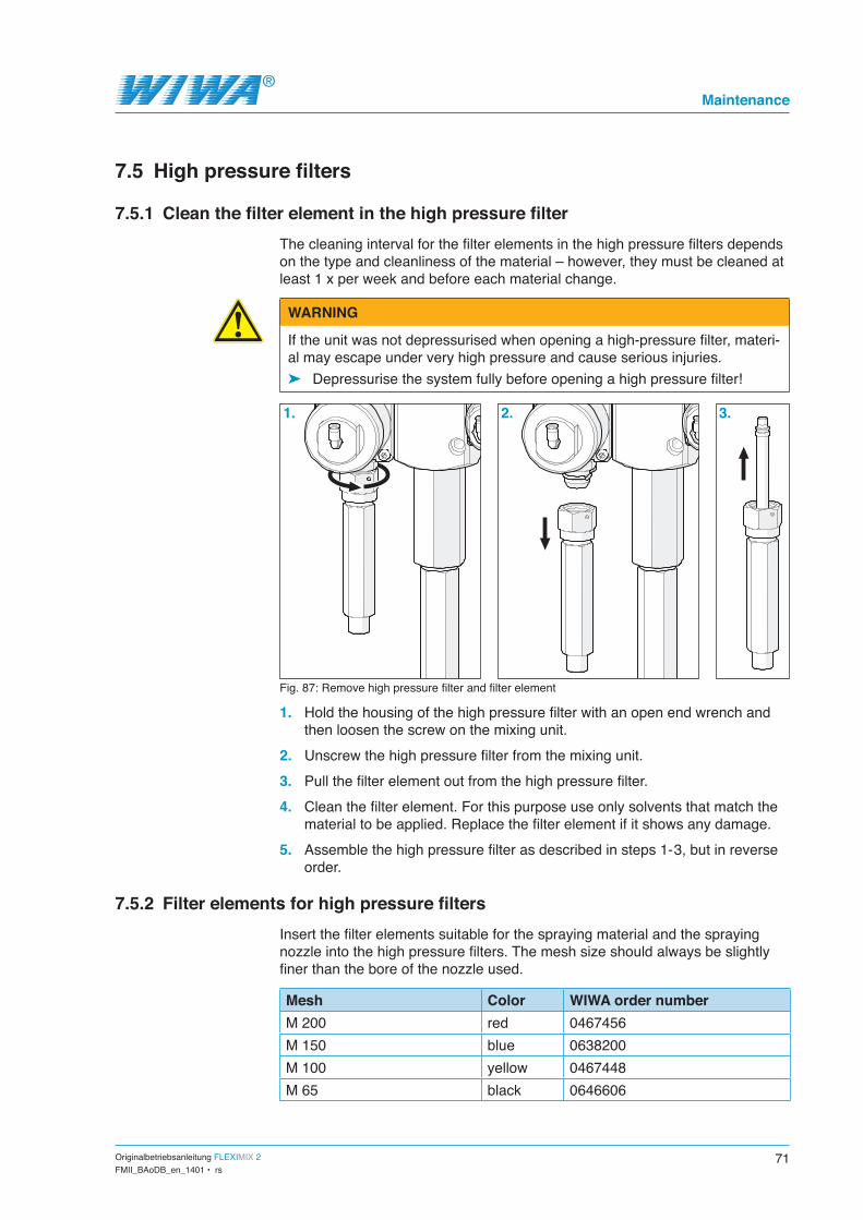
Originalbetriebsanleitung FLEXIMIX 2 71FMII_BAoDB_en_1401 • rs
Maintenance
7.5 High pressure filters
7.5.1 Clean the filter element in the high pressure filterThe cleaning interval for the filter elements in the high pressure filters depends on the type and cleanliness of the material – however, they must be cleaned at least 1 x per week and before each material change.
WARNING
If the unit was not depressurised when opening a high-pressure filter, materi-al may escape under very high pressure and cause serious injuries.
➤ Depressurise the system fully before opening a high pressure filter!
1. 2. 3.
Fig. 87: Remove high pressure filter and filter element
1. Hold the housing of the high pressure filter with an open end wrench and then loosen the screw on the mixing unit.
2. Unscrew the high pressure filter from the mixing unit.3. Pull the filter element out from the high pressure filter.4. Clean the filter element. For this purpose use only solvents that match the
material to be applied. Replace the filter element if it shows any damage.5. Assemble the high pressure filter as described in steps 1- 3, but in reverse
order.
7.5.2 Filter elements for high pressure filtersInsert the filter elements suitable for the spraying material and the spraying nozzle into the high pressure filters. The mesh size should always be slightly finer than the bore of the nozzle used.
Mesh Color WIWA order numberM 200 red 0467456M 150 blue 0638200M 100 yellow 0467448M 65 black 0646606

72 Originalbetriebsanleitung FLEXIMIX 2FMII_BAoDB_en_1401 • rs
Maintenance
Mesh Color WIWA order numberM 60 white 0414700M 30 green 0638201
Do not use a filter element when applying coarse-pigmented or fibre-filled materials. The standard suction strainer should remain in the filter housing or be replaced by a wider mesh screen. In the case of a material change, you must clean or replace both the filter element in the high pressure filter and the material screen in the suction system if necessary.
7.6 Metering pumps
7.6.1 Checking the release agent level in the metering pumpsUnscrew the plug on the filler neck to check the release agent level (see Fig. 88, No. 1 and 2). At an optimum filling level the release agent is visible in the filler neck (approximately 1 cm below the filler opening).Top up with release agent as necessary. The total fill is 50 to 150 ml depending on the pump size. 2
1
Fig. 88: Checking the release agent level
7.6.2 Checking release agent in the metering pumps for material residuesDrain a little release agent from the drain screw to check the release agent for material residue. If the release agent is found to be contaminated with material residues you must assume that the packing of the related metering pump is worn.In this case have the pump packing replaced as soon as possible.
Fig. 89: Release agent drain screw
After checking, top up with the necessary volume of fresh release agent through the filler opening. We recommend to use release agent from WIWA (order no. 0163333).

Originalbetriebsanleitung FLEXIMIX 2 73FMII_BAoDB_en_1401 • rs
Maintenance
7.6.3 Lubricating the gear wheels on the metering pump shaft encodersTo lubricate the gear wheel on the dosing pump shaft encoder you must first unscrew the guard plate from the metering pump (see Fig. 90). Then apply acid-free grease to the gear wheels and racks (see Fig. 91). We recommend using WIWA grease (order no. 0000025).
Fig. 90: Guard plate Fig. 91: Gear wheel
7.7 Metering valves
7.7.1 Checking release agent in the metering valves for material residuesAll metering valves at the mixing unit are equipped with a release agent cham-ber that shields the pneumatic part from the hydraulic part. Drain a little release agent from the drain screw to check the release agent for material residues.
Fig. 92: Drain screw Fig. 93: Covered oiler
If the release agent is found to be contaminated with material residues you must assume that the packing of the related metering valve is worn. In this case have the valve packing replaced as soon as possible. After the exam-ination, top up the release agent through the covered oiler. The release agent chambers must be filled completely.

74 Originalbetriebsanleitung FLEXIMIX 2FMII_BAoDB_en_1401 • rs
Maintenance
7.7.2 Setting the stroke limit on the hardener metering valveThe metering valve for the hardener component has a stroke limitation, which prevents the valve opening for too long. This causes the valve to cycle quicker with finer metering results. Basic position is (the metering valve must be closed and depressurized):1. Loosen the locking nut (2).2. Screw the stroke limiter (1) down fully and
then loosen again by 1 ¼ turns. The stroke limitation may be shortened for high mixing ratios (7:1 -10:1), i.e. only unscrewed by approximately 1 turn after it has been fully screwed down.
3. Tighten the locking nut again to lock in the setting. Pay attention to the stroke limiter to see that it does not lose its adjustment.
Fig. 94: Stroke limiter
1
2

Originalbetriebsanleitung FLEXIMIX 2 75FMII_BAoDB_en_1401 • rs
Troubleshooting
8 Troubleshooting
8.1 Mechanical faultsFault Possible cause/s RemedyMetering pump does not start although the spray gun or the return flow valve on the mixing unit is opened.
1. Compressed air shut-off valve at the meter-ing pump closed.
2. High pressure filter clogged.
3. Air motor defective.
Open the compressed air shut-off valve.
Clean or renew the filter element.
Repair air motor – request WIWA after sales service if necessary.
Metering pump is running but no or too little material is being delivered.
1. Intake or suction hose clogged.
2. Ball of bottom valve does not lift off in the upward stroke (stuck).
3. Bottom valve does not close in the down-wards stroke.
4. Viscosity of the materi-al to high.
5. Air inlet pressure too low.
Clean intake and suction hose.
Tap the bottom valve lightly from the side (hammer). Unscrew the suction system and loosen the ball in the bottom valve from underneath if this does not help.
Unscrew the bottom valve, thoroughly clean the ball and the seat (see repair instructions for the metering pump).
Heat up the Material to reduce the viscosity.
Increase air inlet pressure on compressed air regula-tor. If this does not help, check air line for correct size and compressor output.
The metering pump is running but the required spraying pressure is not being reached.
1. Spray nozzle clogged.2. Spray nozzle too big.3. Spray nozzle worn.4. Air inlet pressure too
low.
Clean spray nozzle. Use smaller spray nozzle. Replace spray nozzle. Increase air inlet pressure on compressed air regula-
tor. If this does not help, check air line for correct size and compressor output.
The metering pump or flushing pump does not stop when the spray gun is closed.
1. Packing or valve worn. Replace worn parts.
The metering pump runs irregularly (can be noticed by differences in up and down stroke speeds) and does not reach the re-quired spraying pressure.
1. Viscosity of the materi-al to high.
2. Suction system leak-ing.
3. Bottom valve leaking (metering pump only stops in upward stroke when the spray gun is closed).
4. Piston valve leaking (metering pump only stops in downward stroke when the spray gun is closed).
5. Bottom or top packing worn.
Heat up the Material to reduce the viscosity.
Check seals and unions in the suction system and replace as necessary.
Unscrew bottom valve, clean and check ball and valve seat, replace ball or valve seat as necessary (see metering pump repair instructions).
Clean and check ball and valve seat in the dual piston, replace ball or valve seat as necessary (see metering pump repair instructions).
Replace the packing (see metering pump repair instructions).
76 Originalbetriebsanleitung FLEXIMIX 2FMII_BAoDB_en_1401 • rs
Troubleshooting
8.2 Alarms
Alarm Cause RemedyDosing error The mixing ratio differs
from the set value (the actual mixing ratio is displayed).
Check: 5 Is there enough material in the containers? 5 Is the mixing unit clogged? Switch the system to flushing
operation and check whether flushing agent is delivered to both the A component side and the B component side in alternating flushing. Should the flushing agent for one of the components not be pumped, this side of the mixing unit is clogged and needs to be cleaned.
5 Is the metering valve of the B component permanently opened and is it no longer cycling or only cycling very slowly and irregularly, before the system shuts down? In this case the stroke limiter for the metering valve is incor-rectly adjusted and needs readjusting.
5 Are the return ball valves on the mixing unit fully closed? 5 Are the ball valves in the suction system open (if present)?
The unit must be flushed to remove the incorrectly mixed material from the unit before spraying operations can be restarted.
Upw.stroke A t.fast,
Upw.stroke B t.fast
The metering pump selected in accordance with the current recipe for the A side or the B side is executing an up stroke too quickly.
Check for the metering pump on the A side or the B side: 5 Is there enough material in the container? 5 Are the return ball valves on the mixing unit fully closed? 5 Has the metering pump been fully vented? Allow the material
to circulate slowly to vent the metering pump. 5 Is the sensor in the metering pump air motor loose?
This can be the case if the fault appears immediately (< 1 second) after the switch over to spraying mode. Check whether the sensor is firmly seated in the downwards stroke of the material pump. The sensor will have to cemented back in if it can easily be moved and the LED lights up and goes out.
5 Is the piston valve of the metering pump closing correctly? Clean ball and valve in the double piston, replace ball and valve seat as necessary.
Downw.stroke A t.fast,
Downw.stroke B t.fast
The metering pump selected in accordance with the current recipe for the A side or the B side is executing a down stroke too quickly.
Check for the metering pump on the A side or the B side: 5 Is there enough material in the container? 5 Are the return ball valves on the mixing unit fully closed? 5 Has the metering pump been fully vented? Allow the material
to circulate slowly to vent the metering pump. 5 Is the sensor in the metering pump air motor loose?
This can be the case if the fault appears immediately (< 1 second) after the switch over to spraying mode. Check whether the sensor is firmly seated in the downwards stroke of the material pump. The sensor will have to cemented back in if it can easily be moved and the LED lights up and goes out.
5 Is the bottom valve of the metering pump closing correctly? Unscrew the bottom valve and thoroughly clean ball and seat if necessary.
Pot life expired Pot life expired. Flush the unit.

Originalbetriebsanleitung FLEXIMIX 2 77FMII_BAoDB_en_1401 • rs
Troubleshooting
Alarm Cause RemedyFill level comp. A,
Fill level comp. B
The fill level in the ma-terial container for the A or B component used in the current recipe has fallen below the minimum volume configured in Con-tainer monitoring.
Top up material.
Error Encoder A 1. The connection of the encoder cable to the encoder of the A com-ponent is loose.
2. The encoder cable is defective.
3. The shaft encoder is defective.
Connect the encoder cable correctly.
Replace the encoder cable.
Replace the shaft encoder.
PLC Low Battery The back-up battery of the programmable logic controller (PLC) is empty.
Save all important data and replace the battery as soon as possible.
Malfunction heaters A_B
The circuit breaker at the material flow heater for the A or B component has tripped
Inform electrician about the problem encountered.
Remote control emergency stop
The emergency stop but-ton at the remote control was pressed.
Check why the button was pressed. If safe operation is ensured, acknowledge the alarm and unlock the emergency stop button.
Malfunction valve 1
Malfunction valve 2
Malfunction valve 3
Malfunction valve 4
1. Metering valve leaking.
2. Bottom valve of meter-ing pump leaking.
3. Piston valve of meter-ing pump leaking.
4. Packing of metering pump worn.
Check the metering valve, readjust or replace the packing as necessary.
Unscrew bottom valve, clean and check ball and valve seat, replace ball or valve seat as necessary (see metering pump repair instructions).
Clean and check ball and valve seat in the dual piston, replace ball or valve seat as necessary (see metering pump repair instructions).
Replace the packing (see metering pump repair instructions).

78 Originalbetriebsanleitung FLEXIMIX 2FMII_BAoDB_en_1401 • rs
Technical data
9 Technical dataYou can find the technical data for your FLEXIMIX 2 in the attached machine card, the type plate or in the documentation for the individual components.
9.1 Machine cardThe machine card contains all important and safety relevant data and informa-tion about the unit.
➤ Exact designation and manufacturer data ➤ Technical data and limit values ➤ Equipment and test certificate ➤ Data of purchasing ➤ Unit identification (unit components and supplied accessories with item
numbers and spare part numbers).
9.2 Type platesThe type plate of the FLEXIMIX 2 is lo-cated on the rear of the rack. It contains the most important technical data for the unit:
➤ the setting range for the mixing ratio,
➤ the output of the metering pumps per cycle,
➤ the pressure ratio,
Gewerbestr. 1 - 3 D-35633 Lahnau
Geräte-Type/Unit
Misch.Verhältnis/MixingRatio
FM p. DH/output p cycle cm³ fl/oz
Übers.-Verhältnis/Ratio /U :1 V
Max.Lufteingang/Air bar psi
Max.Betriebsdruck/Fluid bar psi
Max.Temperatur °C °F
Serial-no.- Model year
0,5:1 - 17:1
Fleximix 2
275
75
6
450
80
9,3
230
87
6525
176
2KED0220 - 2013
www.wiwa.de
Fig. 95: Example of a type plate
➤ the operating voltage, ➤ the maximum air inlet pressure, ➤ the maximum operating pressure, ➤ maximum material processing temperature, ➤ the serial number and the year of production.
Please check that the data on the type plate is identical to the specifications on the machine card. Please notify us immediately in case of discrepancies or if the type plate is missing.
Additionally, some unit components have a separate type plate, such as: ➤ the control panel, ➤ the metering pumps and ➤ the flushing pump.
These type plates contain the technical data and serial numbers of the affected components.

Originalbetriebsanleitung FLEXIMIX 2 79FMII_BAoDB_en_1401 • rs
Hose volumes
10 Hose volumesA hose volume is calculated using the following formula:
Vol = Di ² . π . L4
Vol = Hose volume Di = Inside diameter of the hose L = Hose length
The following table shows the volume of popular hoses:Di L Vol
4 mm 5 m 63 ccm4 mm 7,5 m 94 ccm4 mm 10 m 126 ccm4 mm 12,5 m 157 ccm4 mm 15 m 188 ccm4 mm 20 m 251 ccm4 mm 25 m 314 ccm4 mm 30 m 377 ccm4 mm 40 m 503 ccm4 mm 50 m 628 ccm5 mm 5 m 98 ccm5 mm 7,5 m 147 ccm5 mm 10 m 196 ccm5 mm 12,5 m 245 ccm5 mm 15 m 295 ccm5 mm 20 m 393 ccm5 mm 25 m 491 ccm5 mm 30 m 589 ccm5 mm 40 m 785 ccm5 mm 50 m 982 ccm6 mm 5 m 141 ccm6 mm 7,5 m 212 ccm6 mm 10 m 283 ccm6 mm 12,5 m 353 ccm6 mm 15 m 424 ccm6 mm 20 m 565 ccm6 mm 25 m 707 ccm6 mm 30 m 848 ccm6 mm 40 m 1131 ccm6 mm 50 m 1414 ccm8 mm 5 m 251 ccm8 mm 7,5 m 377 ccm8 mm 10 m 503 ccm8 mm 12,5 m 628 ccm8 mm 15 m 754 ccm8 mm 20 m 1005 ccm8 mm 25 m 1257 ccm8 mm 30 m 1508 ccm8 mm 40 m 2011 ccm8 mm 50 m 2513 ccm
Di L Vol10 mm 5 m 393 ccm10 mm 7,5 m 589 ccm10 mm 10 m 785 ccm10 mm 12,5 m 982 ccm10 mm 15 m 1178 ccm10 mm 20 m 1571 ccm10 mm 25 m 1963 ccm10 mm 30 m 2356 ccm10 mm 40 m 3142 ccm10 mm 50 m 3927 ccm12 mm 5 m 565 ccm12 mm 7,5 m 848 ccm12 mm 10 m 1131 ccm12 mm 12,5 m 1414 ccm12 mm 15 m 1696 ccm12 mm 20 m 2262 ccm12 mm 25 m 2827 ccm12 mm 30 m 3393 ccm12 mm 40 m 4524 ccm12 mm 50 m 5655 ccm16 mm 5 m 1005 ccm16 mm 7,5 m 1508 ccm16 mm 10 m 2011 ccm16 mm 12,5 m 2513 ccm16 mm 15 m 3016 ccm16 mm 20 m 4021 ccm16 mm 25 m 5027 ccm16 mm 30 m 6032 ccm16 mm 40 m 8042 ccm16 mm 50 m 10053 ccm20 mm 5 m 1571 ccm20 mm 7,5 m 2356 ccm20 mm 10 m 3142 ccm20 mm 12,5 m 3927 ccm20 mm 15 m 4712 ccm20 mm 20 m 6283 ccm20 mm 25 m 7854 ccm20 mm 30 m 9425 ccm20 mm 40 m 12566 ccm20 mm 50 m 15708 ccm

Headquarters and production
WIWA Wilhelm Wagner GmbH & Co. KG Gewerbestr. 1 - 335633 Lahnau, GermanyPhone: +49 6441 609-0Fax: +49 6441 609-50E-Mail: [email protected]: www.wiwa.de
WIWA Partnership USAWIWA LP107 N. Main St.P.O. Box 398, Alger, OH 45812Phone: +1 (419) 757-0141Fax: +1 (419) 549-5173Toll Free: +1(855) 757-0141E-Mail: [email protected] Homepage: www.wiwalp.com
WIWA Subsidiary ChinaWIWA (Taicang) Co., Ltd.Building A of Huaxin Industrial Park No.11 East Qingdao Road, Taicang CityJiangsu Province 215400, P.R.ChinaPhone: +86 512-5354 8857 Fax: +86 512-5354 8859E-Mail: [email protected] Homepage: www.wiwa-china.com
WIWA Middle East General Trading LLCMohd Farhan KhanJebel Ali Industrial 1, Dubai, UAEPhone: +9714 884 8220E-Mail: [email protected]
WIWA worldwide field service
Robert JansenSenior Sales Director Finland, Sweden, Norway, Denmark, Great Britain, Southern Ireland, Scotland, England, Holland, Belgium, France, Spain, Portugal, Italy, Croatia, Greece, Czech Republic, Slovakia, Slovenia, Luxembourg, Bulgaria, Egypt, Libya, United Arab Emirates (Oman, Dubai, Abu Dhabi, Qatar, Bahrain), Kuwait, Saudi Arabia, Iran, Iraq, Cyprus, Iceland, Syria, LebanonSupport of WIWA sales directors, representatives and distributors in:South America (except Cuba and Mexico), South East Asia, Japan, South Korea, Australia and New Zealand.Hoekstraat 573751 AL Spakenburg, The NetherlandsMobil: +31 6 18 88 40 97 Phone: +31 3 34 94 69 81 Fax: +31 3 34 94 75 83 E-Mail: [email protected]
Otto Dietrich Sales Director Russia, Ukraine, Belarus, Moldavia, Baltic States (Lithuania, Latvia, Estonia) Caucasian countries (Armenia, Azerbaijan, Georgia), Asian countries (Kazakhstan, Uzbekistan, Turkmenistan, Kyrgyzstan, Tajikistan)Lindenhof 656154 Boppard, GermanyMobil: +49 160 1574385 Phone: +49 6742 899336 Fax: +49 6742 899337 E-Mail: [email protected]
Michel LaksanderTechnical Sales Director France2 Bis rue de légliseF-02240 Brissy Hamegicourt, FrancePhone: +33 32 36 21 120 Mobil: +33 63 70 19 297E-Mail: [email protected]
JK Tan Sales Director Korea, Japan, Australia, South East AsiaMobil: +6012 223 7706Phone./Fax: +603 8024 7706E-Mail: [email protected]
WIWA Service +49 (0)6441 609 140
WWW.WIWA.DE