Embed Size (px)
Citation preview

1
© ® Patent protected
P-Quip Product Manual 32220000
Revision date: July 2014
Web page - http://www.f-e-t.com/PQuip Email – [email protected]
Instructions for the Safe Use & Maintenance of the P-Quip Rod
Systems – Pt. No. 32220000 This product is a direct replacement for the Original Equipment supplied for an Emsco F / FA / FB / FC 1300 and 1600.
Contents: Page 2 Safety notes Page 3 Parts drawings Page 4 Parts lists Page 5 General product information Page 6 Installation information Page 7,8 & 9 Operating instructions Page 10 & 11 Maintenance Page 12 Product Photographs
2
Safety General safety notes:
1) These safety notes should be read in conjunction with local rules and working procedures, particularly where permit to work systems are in place.
2) Prior to working on the mud pump the unit must have its motive power isolated and locked off and hydraulic flow lines isolated and locked off. The pump valve modules should be vented to atmosphere.
3) The following protective clothing should be worn while working with this equipment. Eye protection
suitable to protect from inadvertent discharge of pressurized oil. Foot protection suitable to protect the operator from accidental dropages. Hand protection suitable to protect against the effect of mineral oil on the skin.
4) Great care should be taken when handling this equipment as various components are over 25kg (NOTE: All items heavier than 25kg are marked with their weights) and it may not be practical to use mechanical lifting aids. During initial installation the Power end rod should be handled by two people and mechanical assistance used if possible. If a lifting device is used on the Power End Rod then a suitable endless soft sling should be used, by taking a bite at the balance point. Once the Rod is lifted, the balance should be maintained by steadying the free end manually. During regular use it will be necessary to man handle the Release Link and the Piston Link fitted with a swab. Care must be taken during these operations to position the body over the component being lifted by standing astride the rod in the cofferdam.
5) Extra care must be taken when manually handling these components, as they are prone to become
slippery due to the spillage of oil and mud.
6) Extreme care must be taken when manually rotating the Mud Pump crankshaft pinion, in order to move the rod during assembly and disassembly. The operative handling the rod should be in line of sight and hearing of the operative turning the crankshaft pinion. On NO account must the pumps motive power be used to rotate the pump during this procedure.
Regular safety checks: 1) Check that the appropriate protective clothing warning signs are posted in the pump room or workspace
and are clearly legible.
2) Check that these equipment operating instructions are posted in the pump room or workspace and are clearly legible.
3) Check the hydraulic hose and pressure gauge on the pump is undamaged.
4) Test the hydraulic pump for safety and efficiency by removing the Pinlet adaptor from the end of the
hose and energizing the system to 10000psi / 680bar. Check that the gauge holds the pressure for one minute and that there are no visible leaks. This action will prove the integrity and efficiency of the pump.
5) Check that the Orings on the Pinlet are undamaged and renew as required. These Orings will fail
rapidly due to the fact that in normal use they are pushed pass a hydraulic port that shears small sections of seal away. Should one of the seals fail during normal use the hydraulic fluid will be pumped direct to atmosphere and the only hazard will be the spillage of oil.
3
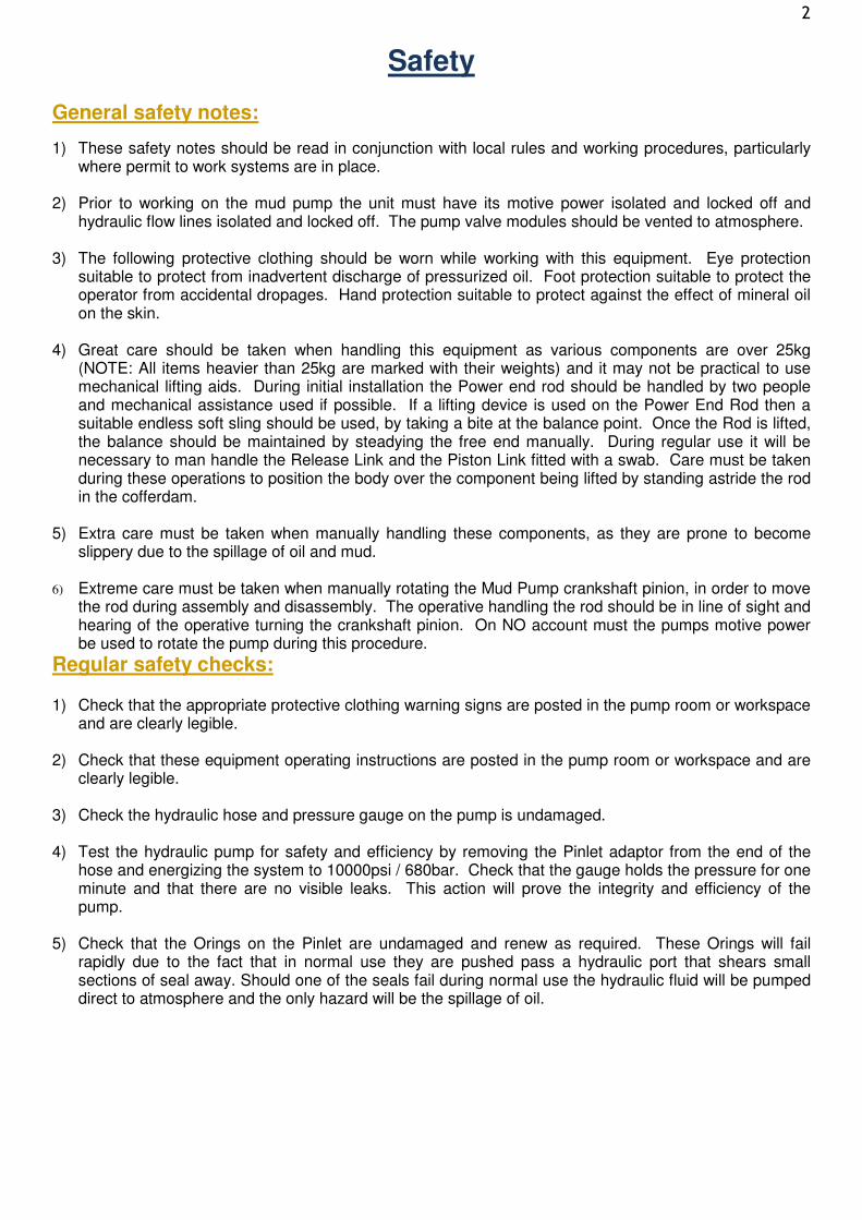
Drawings
Assembly drawing:

4
Parts lists
Product assembly parts List:
Item Part No Description Qty./ Pump Weight
0 32220000 Rod System Assembly. Includes parts 1,2,3,4,5,6,7,9 3 85 kg
1 32220300 Power End Rod / Pony Rod / Crosshead Extension Rod 3 61 kg 2 32220200 Piston Link 3 12 kg 3 30000002 Release Link 3 12 kg 4 32021702 Splash Shield 3 5 30003600 Piston Nut 3 6 30001600 Standard Pin for Use With 5” Liners and Larger 3 7 30007900 Low Profile Pin for Use With Liners smaller than 5” 3 9 31000120 Pin With Liner Flush 3
Product optional extra and tools parts list:
Item Part No Description Qty./ Unit
Qty./ Pump
Weight
8 59000108 Pinlet – Special Pressurizing tool 10 59000110 Pinlet With Adaptor 11 59000113 Hand Operated Hydraulic Pump – not shown 12 59000116 Air Driven Hydraulic Pump – not shown 13 59000130 Piston Nut Wrench – not shown 14 59000121 Pinlet Oring Pack – Contains 10 Orings For Pinlet 15 30008100 Piston Link Holder 15 30008500 Piston Link Puller 21 59000304 Liner Puller 22 P0010** Refer to P-Quip for correct piston / swab part number
Recommended spares The following parts should be held on the rig as spares. The life expectation of all parts other than consumables is many years.
Quantity Part No Description Reason
6 32220200 Piston Link For fast change out
2 30000002 Release Link For damage spare 1 32021702 Splash Shield For damage spare
1 32220300 Power End Rod For damage spare
20 30003600 Piston Nut Consumable
6 30001600 Pin For loss spare
2 31000120 Pin With Liner Flush For damage spare
2 59000110 Pinlet Adaptor Essential tool
10 59000121 Pinlet Oring Pack Essential tool consumable
5
General product information
Specification:
This product is a direct replacement for the Original Equipment supplied for an Emsco F / FA / FB / FC 1300 and 1600 mud pump. It is designed to allow faster and safer swab removal and changing. The selected materials of manufacture will lead to a longer efficient working life.
1) This product is designed to work up to the maximum pump pressure recommended by the Mud Pump
Manufacturer.
2) The working pressure of the Release Link is 545bar / 8000psi.
3) The weights of the various components are clearly marked on the product and on page 4 of this document.
4) The noise level of this product does not exceed 70 dB(A).
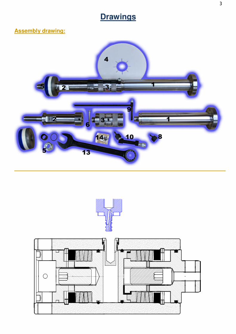
Principles of operation:
1. Hydraulic pressure is applied through the Pressure Fitting (Pinlet).
2. Hydraulic pressure is fed to both release link pistons simultaneously.
3. The Pistons are thus forced against the springs, causing them to be compressed.
4. The release link connectors are forced out until their holes align with those in the power end rod and the piston link, enabling the pins to be fitted.
5. When the pressure is released the springs will apply their force to placing the pins in shear,
which will securely attach the components together.
6. In the operational situation the springs are fully compressed and the internal pressure is zero.
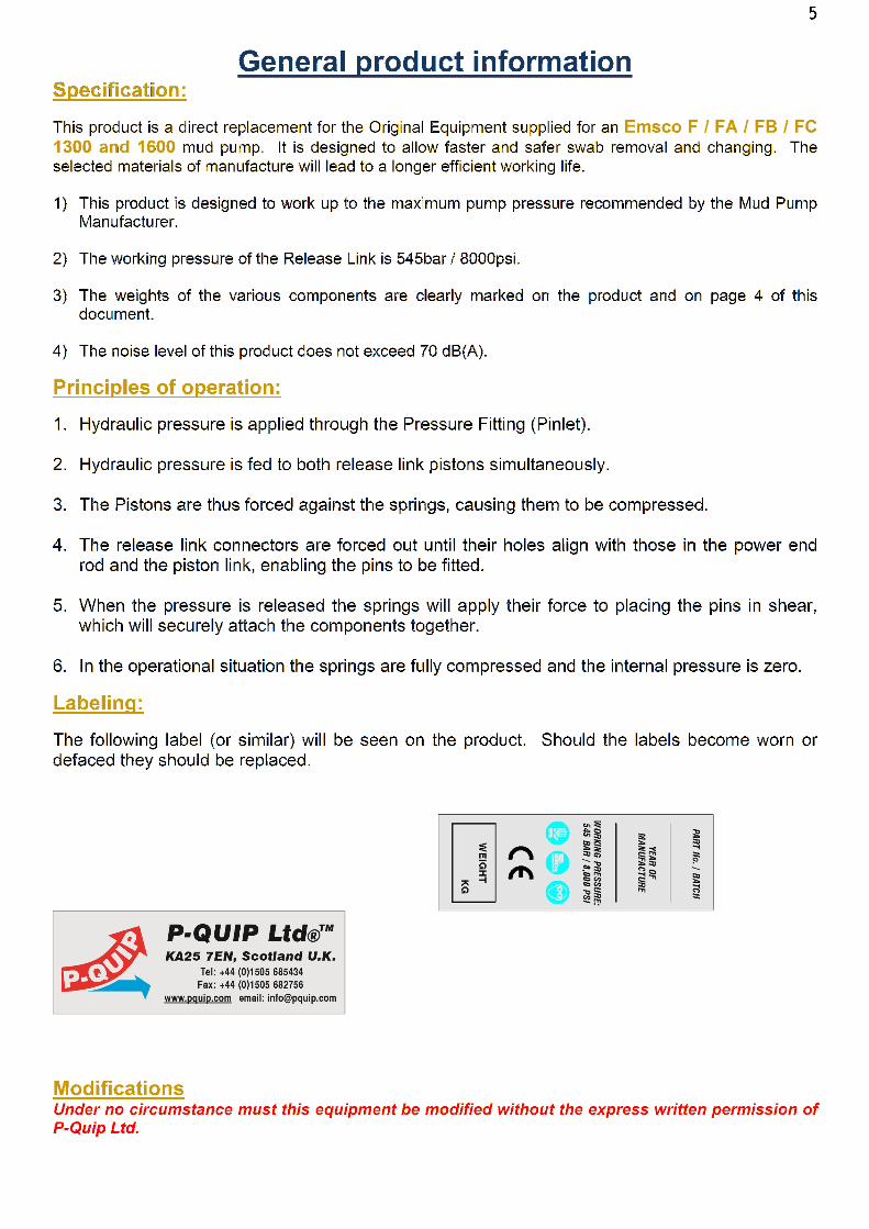
Labeling:
The following label (or similar) will be seen on the product. Should the labels become worn or defaced they should be replaced.
Modifications Under no circumstance must this equipment be modified without the express written permission of P-Quip Ltd.
6
Installation
Installation and preparation instructions:
1) If an Original OEM rod system is fitted to the mud pump, this should be completely removed, following the instructions given in the OEM instruction manual. Lay the original rod system safely to one side for disposal.
2) The Power end Rod (1) should be fitted in the same manner as the OEM one, following the OEM instructions.
3) The original power end seal arrangement will then be re-fitted as per OEM instructions. It is advisable
to fit new wiper seals at this time.
4) Push the Splash Shield (4) on to the Power end rod (1) until it locates in the groove near the end of the rod.
5) Prepare the hydraulic pump (11 or 12) by removing the transport plug and replacing with the vented
filler plug. Top up the hydraulic pump with hydraulic oil (preferably EP32 but any grade will be adequate).
6) When an air driven hydraulic pump (12) is used, connect the pump to a suitable air supply using a
length of standard air hose. The air supply should be fitted with a water separator, a lubricator and a pressure regulator set to 110 psi / 7.5bar.
7) Fit the Pinlet Adaptor (10) to the pump hose coupling. Briefly run the pump until a flow of oil is emitted
from the Pinlet. This has the dual purpose of eliminating air from the system and confirming that the quick connectors are assembled correctly. NOTE: Do not leave the Pinlet Adaptor (9) attached to the hose, as there will be a tendency for the hydraulic oil to siphon from the pump.
8) Install the Piston Link Holder (15) in a suitable location within the pump room. This tool is designed to
safely retain the Piston Link (2) while the Piston Nut (5) is being tightened on to the swab. The Holder should be bolted or welded to a suitable static point, bench or pump frame. It is designed to allow the nut to be tightened or loosened by pulling down on the wrench (13), depending in which end of the tool the Piston Link (2) is fitted.

7
Operating instructions
Operating Instructions: Fitting a Piston / Swab to the Piston Rod 1) Select the appropriate size of Piston/Swab to be fitted to the Piston Link (2). Note that P-Quip Pistons
are recommended for use with these rod systems.
2) Clean the mating surfaces of the Piston Link and the Swab. If any nicks or burrs are noticed on the sealing face, they should be carefully removed by filing and rubbing with emery.
3) The sleeve that is supplied with the swab must be utilized as the Piston Link has a 1 ½” stud.
4) Ensure that the O’ring supplied with the swab is lightly coated with GP grease and carefully fitted in its
groove prior to sliding the swab on to the Piston Link.
5) Utilizing the Piston Link Holder (15), fit a fresh Piston nut (5) and tighten to 750 lb. ft. / 1000N.m. using the Piston Nut Wrench (13) followed by final tightening with a torque wrench. NOTE: Piston Nuts (5) should be discarded after 2 or 3 uses, as the nylon locking mechanism becomes ineffective over time. If the Piston Nut should back off during use, severe damage could be caused to the pump. Note that the Piston Link Holder (14) is designed to allow the nut to be tightened or loosened by pulling down on the wrench (13), depending in which end of the tool the Piston Link (2) is fitted.
Operating Instructions: Fitting A Rod Dressed with A Swab into the Pump. 1) Assembling a rod into the pump is a two-person job.
2) Rotate the pump crankshaft pinion using the process provided by the pump manufacturer, until the
selected Power End Rod is fully backed off away from the liner.
3) Select the Piston Link (2) to be used and liberally coat the fitted swab with general purpose grease. Hold the Piston link and swab in the mouth of the liner with the pin hole approximately vertical. Carefully rotate the crankshaft taking particular care with regard to the finger pinch point between the two rods. From the full back position the Power End Rod should be rolled forward approximately 272mm. This will be far enough to enter the piston into the liner whilst still allowing the Release link to be entered in to the gap produced by returning the Power End Rod to the full back position. Ensure that the lip of the swab is not damaged or distorted as it initially enters the liner. Reverse the rotation of the crank shaft until the Power end Rod is fully stroked back.
4) Take a Release link (3) and slide its female end over the spigot on the end of the Power End Rod (1).
Rotate the Release Link on the spigot until it is orientated with the pin hole at the female end vertical or in line with the hole in the Power End Rod and the Pinlet hole towards the top.

8
5) Push the Pinlet Adaptor (10) fully into the central aperture in the Release Link. Energize the hydraulic pump to 8000psi / 545bar. Close the hand valve on the pump to retain the pressure within the system. At this pressure it will be possible to easily push a pin (6), coated with high temperature grease, through the holes in the Power End Rod and the Release Link. The alignment of the pin will be aided by lifting the free end of the Release Link so that it is not drooping. Note carefully that NO HAMMERING will be necessary.
6) Carefully rotate the crankshaft taking particular care with regard to the finger pinch point between the
Release Link and the Piston Link, until the spigot of the Release link just enters the Piston Link end hole. At this time the spigot of the Release Link should be rotated, using any pin type tool, until the holes in the Release Link Spigot and the Piston link are aligned.
7) Continue forward until all the gaps between the rod sections are closed up. It will now be possible to
easily enter second pin or the pin of the Liner Flush (7), coated with high temperature grease. If difficulty is experienced in entering the pin check that the holes are aligned and that the stated pressure is still retained within the unit. Note carefully that NO HAMMERING will be necessary.
8) Open the valves on the hydraulic pump to release the pressure in the Release Link. The rod will be
observed to become rigid and all the gaps will close up. Disconnect the hose from the Pinlet Adaptor. The Pinlet Adaptor may now be pulled free of the Release link.
9) The OEM liner flushing flexible pipe-work system should now be connected to the 3/8” BSP fitting on the Pin With Liner Flush (7).
10) The above procedure should now be repeated for the remaining two, rod systems.
Operating Instructions: Removing a Rod / Swab from the Pump.
1) Removing a rod from the pump is a two-person job.
2) Rotate the pump crankshaft pinion using the process provided by the pump manufacturer, until the selected Power End Rod is fully backed off away from the liner.
3) Push the Pinlet Adaptor (8) fully into the aperture in the Release Link. Connect the pump hose to the
Pinlet Adaptor. Energize the hydraulic pump to 8000psi / 545bar. Close the hand valve on the pump to retain the pressure within the system. At this pressure it will be possible to easily pull the Pin from the hole in the Piston Link end of the Release Link. Note carefully that NO HAMMERING will be necessary. Leave the other pin in place.
4) Carefully rotate the crankshaft, until the Piston link is pushed approximately 72mm back into the liner.
5) Carefully rotate the crankshaft in the opposite direction, until the rod is once again fully back stroked.
6) Pull the remaining pin (6) through the holes in the Power End Rod and the Release Link. The removal
of the pin will be aided by lifting the free end of the Release Link so that it is not drooping. Note carefully that NO HAMERING will be necessary.
7) Lift the Release link (3) clear of the spigot. If just one swab is being removed, it will not be necessary to
disconnect the pressurized Pinlet. The Release Link, with the hydraulic hose still attached should be laid in the bottom of the cofferdam. If the operation requires the use of the hydraulic pump elsewhere then the pressure should be released and the Pinlet withdrawn from the Release Link.

9 8) Connect the Piston Link Puller (16), using the pin (6), to the exposed end of the Piston Link (3),
projecting from the liner.
9) Carefully rotate the crankshaft taking particular care with regard to the pinch point between the Power
End Rod and the Piston Link, until the spigot of the Power End Rod (1) is at a suitable distance to allow the Piston Link Puller to be connected to it, using a spare pin (6). It may be necessary to adjust the length of the chain on the Piston Link Puller to gain the best effect.
10) Rotate the crankshaft in the opposite direction thus pulling the Piston link and swab from the liner. It
may be necessary to repeat this operation with a shortened chain link on the Piston Link Puller. Care must be taken to manually support the swab end of the piston link as it exits the liner. The Puller Tool will support the outer end.
11) Disconnect the Puller Tool and lift out the Piston Link.

10
Maintenance instructions
Maintenance / Troubleshooting
1) Preferable hydraulic oil; ISO grade 32; ISO oil type HM. – This material has no known hazard as defined by local laws. This material if discarded is not expected to be a characteristic hazardous waste. Disposal should be in compliance with federal, state and local laws. All components are in compliance with EC Seventh Amendment Directive 92/32/EEC. Toxic fumes or vapors may evolve on burning.
2) Power End Rod (1): The surface of the power End Rod is coated with hard chrome to prevent wear caused by rubbing against the crank case wiper seals. This chrome surface should be protected from impact damage or excessive wear caused by worn or damaged wiper seals. Should the surface become so worn that the wiper seal is ineffective it will normally be possible to repair the surface. Please seek advice from P-Quip. If the spigot hole becomes distorted due to an extraordinary force being applied, it will not normally be possible to effect a satisfactory repair and the unit should be replaced.
3) Piston Link (2) Clean the mating surfaces on both ends of the Piston Link. If any nicks or burrs are
noticed they should be carefully removed by filing and rubbing with emery. If the spigot hole becomes distorted due to an extraordinary force being applied, it will not normally be possible to effect a satisfactory repair and the unit should be replaced.
4) Release Link (3): Site repairs are not possible on this component, as it is factory set and sealed.
Before a decision is made to discard this device the following points should be checked:-
1. If the unit will not energize because the oil is flowing straight back out from the Pinlet area then the fault is almost always that the Pinlet Orings (12) are damaged and require to be changed.
2. If the unit will not pressurize but no leak is apparent, then the fault must be with the pump. Check the pump by removing the Pinlet Adaptor (8) and pressurizing against the closed hose.
3. If it is not possible to enter pins at the appropriate pressure then an attempt should be made to assemble the unit to spare mating parts on the bench so as to eliminate damage or misalignment of the mating components.
4. The unit has a working pressure of 545bar / 8000psi. It may however be found that the pin holes line up at 240bar / 3500psi. This is the acceptable, efficient working range.
5) Piston Nut (5). Piston Nuts should be discarded after 2/3 uses, as the nylon locking mechanism becomes ineffective. If the Piston Nut should back off during use, severe damage could be caused to the pump.
6) Pin (6) Check pins regularly for straightness and scoring. Slight scoring may be dressed out by hand, otherwise a damaged pin must be discarded.
7) Pinlet (9) No attempt should be made to repair these units other than the fitting of new Orings (12).
When a new Pinlet is being fitted to the Adaptor (9) the assembly should be pressure tested by applying the unit to a Release link (3) and energizing it. It is recommended that the outer O’ring (13) on the Pinlet be replaced once a series of energizing actions are complete as this O’ring will become damaged by use.
8) Hydraulic Pump (11 or 12) Refer to manufacturer instructions.
9) Failure to Release: In the unlikely event that the unit will not pressurize it will be possible to remove
the pins by hammering with an engineer’s hammer and a punch. If this proves too difficult to do from underneath then the head of the pin can be cut off using a cutter grinder and knocking the pin through from the top. Should this extreme method be resorted to then local safe working methods must be adhered to.
10) Pump Alignment Checking: The assembled rod system cannot be used to check the axial alignment
between the crosshead and the liner. The rod is equipped with the means to self-align with a slightly misaligned pump and as such will not centralize until a swab is fitted.

11 11) Periodical Testing: The Release Link (3) will require to be checked for efficient operation on an
annual basis. The springs in the Release Link will eventually fatigue causing inefficient tension to be applied to the pins (6). The method of testing this is simple yet effective. With the rod assembled on the bench, preferably using all new connecting parts, the pin (6) should be tapped firmly with a hand hammer to assess its tightness. The pin should require considerable effort to move it. If this test is carried out on new equipment, the operator will have a datum measurement of the “feel” of the required tightness. The Release link will continue to work efficiently until there is a danger of the pin falling out or the Piston Link (2) turning during normal operations.

12
Product photographs