Embed Size (px)
Citation preview

MEASUREMENT AND ASSEMBLY MANUAL
Validity of the manual: 1. 6. 2017 1
SCREEN HR7, HR8-ZIP
1. LIST OF REQUIRED TOOLS
• Ladder
• Dril
• Crosshead screwdrivers
• Set of metal dril bits
• Masonry dril bits (6 mm and 8 m)
• Set of Allen keys
• Pop rivet tool
• Tape measure and pencil
• Spirit level, plumb line and hose level
• Voltmeter or test lamp 220 V
• Test cable with switch
• Silicon caulk or joint sealing strip
2. ASSEMBLY
2.1. CHECK THE PROVIDED PARTS
Check the provided parts and open the bag containing the fittings. Divide the screws, plugs, washers and caps equally
between the guide rails. You should have an equal amount of fastening material for each guide rail.
2.2. CHECK THE HEIGHT AND WIDTH
Measure the width of the screen box and the window opening, then determine whether the box is the right size for the installation situation. Also check the height from the top of the box to the bottom of the guide rails, including the end stops. Measure the inside height of the window frame. Check whether they match, taking the mounting bracket into account.

MEASUREMENT AND ASSEMBLY MANUAL
Validity of the manual: 1. 6. 2017 2
HR7: HR8-ZIP:
fig. 1
Final width B = the distance between the end brackets.
Final height H = the height including box and guide rail ends (thickness = 2 mm) except the mounting bracket.
Note: the final height H with steel cable from the top edge of the box to the lower side of the bottom rail.
2.3. DRILL THE HOLE FOR THE LEAD-THROUGH
Measure the position of the control lead-through on the screen box. Mark this on the window frame.
Drill the hole for the control lead-through through the window frame:
For motorised operation use a 10 mm drill bit; see fig. 3 on page 3.
For crank handle operation use a 14 mm drill bit; see fig. 2 on page 3.
For exterior crank handle operation with eye you do not have to drill a lead-though.
Attention! Do not drill into the window glass.
MEASUREMENT AND ASSEMBLY MANUAL
Validity of the manual: 1. 6. 2017 3
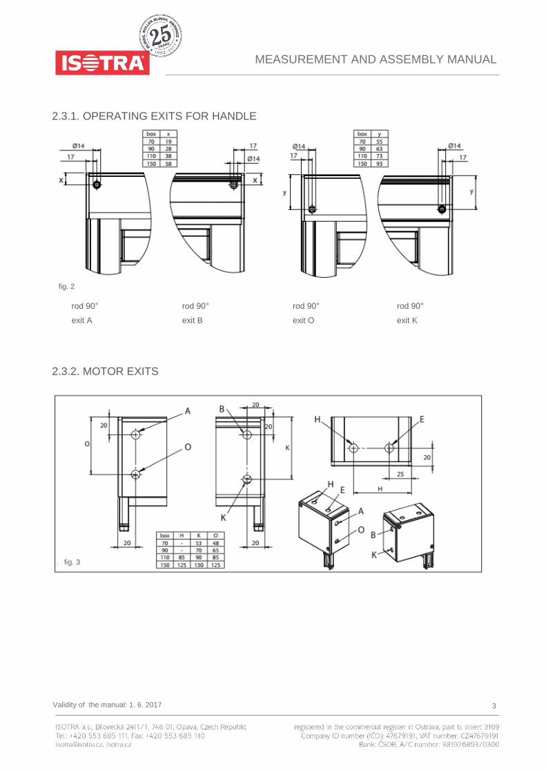
2.3.1. OPERATING EXITS FOR HANDLE
rod 90° rod 90° rod 90° rod 90°
exit A exit B exit O exit K
2.3.2. MOTOR EXITS
fig. 2
fig. 3

MEASUREMENT AND ASSEMBLY MANUAL
Validity of the manual: 1. 6. 2017 4
2.4. PRE-DRILLING THE GUIDE RAILS
Guide
rail
Drilling on the
side
Drilling in the
back Clip mounting*
Sealing
strips**
Distance
support*** End stop****
725
720
728
755
756
829
820

MEASUREMENT AND ASSEMBLY MANUAL
Validity of the manual: 1. 6. 2017 5
828
855
856
839
830
838
865
866

MEASUREMENT AND ASSEMBLY MANUAL
Validity of the manual: 1. 6. 2017 6
* Clip mounting These guide rails have two small L-shaped notches on the back. These are either used for clipping the guide rails to the window frame, using the provided clips, or they are fitted with sealing strips. The clips must be screwed on each side of the window frame in one straight and vertical line.
** Sealing strips
When the screen is mounted to a window frame on which the surfaces for the two guide rails are not flush, the resulting
gaps between the guide rails and the window frame can be sealed with sealing profiles. These sealing profiles must always be secured by a screw at the top and the bottom of the guide rail. Be careful when
tightening the fasteners, because overtightening can permanently damage the sealing profiles.
In the interest of safety, it is important that each guide rail be additionally secured to the window frame at the top, middle and bottom with a sheet metal screw to prevent the guide rail from sliding and the clips from detaching from the screen.
*** Distance supports For guide rails with a mounting flange (type 828), distance supports can be used for mounting the guide rails.
**** Cover cap For each of the guide rails of the type referred to above, use a cover cap at the bottom end. This will prevent the bottom
slat from dropping out of the guide rails.
U-shaped guide profile: A plastic screen guide profile fits into the U-channel of each guide rail, which accommodates the zipper on the fabric. (At the top end of this extrusion, the black rubber part is cut away at an angle over a length of 70 mm. Make sure the guides are positioned with these cut-aways at the top. The screen guide profiles for the left and right sides
differ.)
2.5. PIN MOUNTING
In this installation the box is mounted onto the guide rails by sliding the pivots on each of the side consoles into the
corresponding hole chambers on the guide rails.
To make some of the following steps easier, it is recommended that you unroll the screen a bit so the bottom slat extends
a few centimetres from the box. To do so, use a test cable to briefly operate the motor or operate the manual gearbox with
a crank handle attached to a square rod inserted through the opening in the box.
Based on the installation situation, there are several ways the screen can be installed:
Method 1. Affix the box using the mounting brackets, then slide the guide rails onto the console pivot and secure the guide
rails with screws.
Method 2. Place the complete box / guide rail assembly in or against the window opening and screw them in place.
Mehtod 3. Screw the guide rails in place. Then push the box onto the guide rails and secure it in place.

MEASUREMENT AND ASSEMBLY MANUAL
Validity of the manual: 1. 6. 2017 7
2.5.1. METHOD 1 – AFFIX THE BOX USING THE MOUNTING BRACKETS, THEN SLIDE
THE GUIDE RAILS ONTO THE CONSOLE PIVOT AND SECURE THE GUIDE RAILS
WITH SCREWS
Step 1: Drilling holes for the mounting brackets
Box type X
70 37
90 53
110 73
150 114
spirit level
Place the mounting brackets against the
mounting surface. Use the upper holes for
mounting against a ceiling and the rear
holes for mounting against a wall.
The box must be perfectly level, so make
sure the brackets are aligned properly. Use
a hose level and a plumb line or another
suitable tool for this task.
fig. 4
fig. 5 fig. 6

MEASUREMENT AND ASSEMBLY MANUAL
Validity of the manual: 1. 6. 2017 8
Step 2: Installing the box on the mounting brackets
One mounting bracket per console, as close as possible to the console.
Any additional brackets are mounted in the middle of the box, evenly spaced across its width, and are intended to prevent
wider boxes from sagging.
(1) Push the box upwards into the mounting brackets.
(2) Feed the motor cable through to the inside. Then push the box into the brackets so the slots in the back of the box
engage with the L-profiles. (3) Next tighten the Allen screws of each bracket. The screws should grip in the slots at the top of the front of the box.
Step 3: Drilling the mounting holes for the guide rails
Mark the holes to be drilled on the wall or on the
mounting surface. Use the pre-drilled lateral guide rails
for this procedure. Drill the holes in the wall (Ø6 mm)
or in the window frame (Ø3.2 mm).
For installation to the wall, insert S6 plugs into the
holes.
Step 4: Installing the guide rails
(1) Affix the clips to the mounting surface. Next slide the guide rails onto the guide rail pivots of the side consoles. Make sure the sliding blocks of the bottom slat enter the guide rail slots correctly and the zipper on the fabric slides into the U-shaped part of the plastic guide profile.
(2) Screw the guide rails to the mounting surface.
fig. 7
through hole chamber of guide
rail
through hole chamber of guide
rail
of guide rail
for clips
fig. 8
fig. 9

MEASUREMENT AND ASSEMBLY MANUAL
Validity of the manual: 1. 6. 2017 9
fig. 10 fig. 11
fig. 12
fig. 13

MEASUREMENT AND ASSEMBLY MANUAL
Validity of the manual: 1. 6. 2017 10
2.5.2. METHOD 2 – PLACE THE COMPLETE BOX / GUIDE RAIL ASSEMBLY IN OR
AGAINST THE WINDOW OPENING AND SCREW THEM IN PLACE
Box type X
70 37
90 53
110 73
150 114
Step 1: Drilling holes for the mounting brackets and guide rails
Mark the holes to be drilled on the wall or on the
mounting surface (use the pre-drilled lateral guide rails
for this purpose).
(If supplied, affix the box mounting bracket(s) first.)
Drill the holes in the wall (Ø6 mm) or in the window frame (Ø3.2 mm).
For installation to the wall, insert S6 plugs into the
holes.
Affix the clips to the mounting surface.
spirit level
through hole
chamber of guide
rail
through hole
chamber of guide
rail
for clips
fig. 14
fig. 15
Obr. 16

MEASUREMENT AND ASSEMBLY MANUAL
Validity of the manual: 1. 6. 2017 11
Step 2: Sliding the guide rails over the console
pivots on the bottom of the box
Place the screen box on the cardboard packaging
(take care not to damage the paint finish).
Next slide the pre-drilled guide rails onto the console
pivots on each of the side consoles.
Make sure the sliding blocks of the bottom slat enter
the guide rail slots correctly and the zipper on the
fabric slides into the U-shaped part of the plastic guide
profile.
Step 3: Positioning the box and the guide rails
Now lift the screen box with the guide rails. Do this
with at least two persons. Support the box and the
guide rails at the same time.
Place the complete screen assembly in or against the
window opening.
For motorised operation, feed the motor cable inside through the previously drilled lead-through.
Attention! Be careful not to break off the pivots of the box by moving the guide rails too much forwards, backwards or sideways.
fig. 17
fig. 19
fig. 18

MEASUREMENT AND ASSEMBLY MANUAL
Validity of the manual: 1. 6. 2017 12
Step 4: Attaching the box to the mounting brackets and screwing the guide rails in place
(1) Push the box upwards into the mounting brackets. (2) Feed the motor cable through to the inside. Then push the box into the brackets so the slots in the back of the box engage with the L-profiles. (3) Next tighten the Allen screws of each bracket. The screws should grip in the slots at the top of the front of the box.
Screw the guide rails to the mounting surface.
Make sure the box is always securely mounted. See section „Installation of controls“.
fig. 20 fig. 21

MEASUREMENT AND ASSEMBLY MANUAL
Validity of the manual: 1. 6. 2017 13
2.5.3. METHOD 3 – SCREWING THE GUIDE RAILS IN PLACE AND THEN PUSHING
THE BOX ONTO THE GUIDE RAILS (ONLY FOR SCREENS WITHOUT MOUNTING
BRACKETS
Step 1: Drilling mounting holes and affixing the
clips
Mark the holes to be drilled on the wall or on the
mounting surface (use the pre-drilled lateral guide
rails for this purpose).
Drill the holes in the wall (Ø6 mm) or in the window frame (Ø3.2 mm), no more than 500 mm apart.
For installation to the wall, insert S6 plugs into the
holes.
Affix the clips to the mounting surface.
spirit level
through hole
chamber of guide
rail
through hole
chamber of guide
rail
for clips
fig. 24
fig. 22
fig. 23

MEASUREMENT AND ASSEMBLY MANUAL
Validity of the manual: 1. 6. 2017 14
Step 2: Mounting the guide rails
Screw the guide rails to the mounting surface. Make
sure the top of the guide rails are positioned at exactly
the same height and are level.
Step 3: Sliding the screen box onto the guide rails
Lift the box and feed the motor cable to the inside.
Slide the screen box so the console pivots fit into the
corresponding hole chambers of the lateral guide rails.
Make sure the sliding blocks of the bottom slat enter
the guide rail slots correctly and the zipper on the
fabric slides into U-shaped part of the plastic guide
profile.
fig. 25
fig. 26
fig. 27

MEASUREMENT AND ASSEMBLY MANUAL
Validity of the manual: 1. 6. 2017 15
Make sure the box is always securely mounted. See section „Installation of controls“.
2.6. CHECKING FOR SQUARENESS
Always make sure the screen is installed perfectly level and square.
There is only one way to check and correct this.
1. First check whether the box is mounted perfectly level.
2. Check whether the guide rails run parallel to each other and
perpendicular to the box. Measure the diagonals to the
nearest millimetre. Start directly beneath the box. Deviations
of more than 2 mm may cause the fabric and/or bottom slat to
get stuck or the fabric to hang loosely.
3. Next measure the diagonals to the nearest millimetre.
If the box and guide rails are not mounted properly, the bottom slat will
always roll into the box at an angle, resulting in diagonal creases in the
fabric.
Once the screen has been accurately positioned and mounted, any small gaps between the guide rails and wall (box and
wall) can be sealed with silicon caulk.
fig. 29
fig. 28

MEASUREMENT AND ASSEMBLY MANUAL
Validity of the manual: 1. 6. 2017 16
3. GENERAL INFORMATION
3.1. CHECKING THE INSTALLATION
The installation is checked by testing its functionality. The screen is lowered and raised again. This should proceed
smoothly, and no creases should develop during lowering.
3.2. MOUNTING THE BOX
This can be done in several ways:
Secure the box by hanging it from the mounting brackets (see method 1), or
- Open the box. Remove the fabric roll from the box by tapping upwards on the fabric roll so the end pops out of the click-in retainer. Affix the box to the mounting surface with the extra pan head screws (through the back or the top of the box). Do this for each console and in the centre. Re-install the fabric roll and the box cover.
3.3. FINISHING
Space between screen box and wall
Apply a small amount of silicon caulk in the gap between the screen box and mounting surface in order to prevent any
potential movement. To fill the gaps at the top and the sides (between the screen box and the mounting surface when mounting brackets
are used), you can use joint sealing strip or the special U-profile (see points G3 and G4) which is available separately..
Space between guide rails and wall
Apply a small amount of silicon caulk in the gap between the guide rails and mounting surface in order to prevent any
potential movement.
DVC/DVS
When installing DVC/DVS linked screens, it is recommended that one person be available to push each guide rail onto
the console pivot, the bottom slat into the guide rail and the zipper into the grey U-shaped part of the plastic guide
profile.
4. INSTALLATION OF CONTROLS
4.1. ELECTRICAL CONNECTIONS
Note: The connections must be made by a qualified installer (refer to guarantee card 2.1). Electrical installation and
connection diagrams must be followed correctly. The electrical accessories employed must comply with the current
standards and/or requirements.

MEASUREMENT AND ASSEMBLY MANUAL
Validity of the manual: 1. 6. 2017 17
4.2.1. WIRING DIAGRAM FOR A SINGLE POLE SWITCH
The motor has 4 wires. Yellow/green (earth), blue (neutral), brown and black (up and down control). There should be three
wires available from the protected mains circuit. Yellow/green (earth), blue (neutral) and phase wire. Connect the wires
according to the diagram. The phase wire from the electrical mains is connected to terminal L. If necessary, exchange the
brown and the black wires from the motor at the switch so that the arrows on the switch correspond to the up and down
movement of the screen. The two earth wires are connected together by means of separate wire clamps. The same
applies for the two neutral wires.
Connecting and installing the motor:
Lead the motor cable to the control switch until it is out of sight where
possible.
Connect the motor cable and the power supply to the single pole
switch. See above.
Exchange the brown and black wire if necessary so the arrows on the
switch correspond with the movement.
When two or more motors are connected to a single switch, use of
one or more relay boxes is required. Refer to diagram RI2 for making
the connections.
fig. 30
fig. 31

MEASUREMENT AND ASSEMBLY MANUAL
Validity of the manual: 1. 6. 2017 18
Remark concerning the motor: If the motor is of the standard LT type, you can continue following the instructions in this manual. For the LS motor, the
stop positions are not set with push buttons but rather with Allen key setting pins (consult the accompanying manual).
If an Altus RTS type is used, consult the instructions that accompany the motor.
4.2.2. CALIBRATING THE MOTOR – LIMIT SWITCHES
Temporarily connect the test cable to the motor.
4.2.2.1. LOWERING THE SCREEN WITH THE MOTOR – SETTING THE END POSITION
DOWN
Lower the screen with the motor. Make sure it stops at the correct point and not past the lower stop position, as the screen
could otherwise be rolled up in reverse, causing damage.
The motor limit switches have not been calibrated. Both buttons on the motor have been completely pushed in at the
factory (or press them both in if that is not the case). As a result, the motor will not stop on its own.
Lower the screen until the desired bottom position has been reached. Then put the switch in its neutral position.
Now push the white button (or yellow button, depending on the orientation of the motor) so the button pops out slightly.
The lower stop position has now been set.
4.2.2.2. RAISING THE SCREEN WITH THE MOTOR – SETTING THE END POSITION UP
Now raise the screen with the motor. Make sure it
stops in time, just below the upper stop position.
Then put the switch in its neutral position.
Now push the yellow button (or white button,
depending on the orientation of the motor) so the
button pops out slightly. The upper stop position has
now been set.
The two stop positions have now been set.
If it becomes necessary to calibrate the motor stop
positions again, the procedure can be repeated by
simply pushing in both buttons. This clears the stop
position settings so new settings can be made by
following the instructions beginning at 4.2.2.
Why use an RI2 relay box?
If several LT or LS motors are operated using the
same switch, you must always use a relay box. If
relay boxes are not used, the system will oscillate
and the resulting high inductive and capacitive
fig. 32
MEASUREMENT AND ASSEMBLY MANUAL
Validity of the manual: 1. 6. 2017 19
voltages will burn out the switches inside the motor housing.
Thus heed the following advice: Always use the relay boxes and switches supplied by us, to control two or more motors
with a single switch. The same applies when using an wind/sun automatic controller.
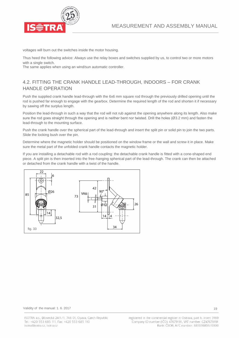
4.2. FITTING THE CRANK HANDLE LEAD-THROUGH, INDOORS – FOR CRANK
HANDLE OPERATION
Push the supplied crank handle lead-through with the 6x6 mm square rod through the previously drilled opening until the
rod is pushed far enough to engage with the gearbox. Determine the required length of the rod and shorten it if necessary
by sawing off the surplus length.
Position the lead-through in such a way that the rod will not rub against the opening anywhere along its length. Also make
sure the rod goes straight through the opening and is neither bent nor twisted. Drill the holes (Ø3.2 mm) and fasten the
lead-through to the mounting surface.
Push the crank handle over the spherical part of the lead-through and insert the split pin or solid pin to join the two parts.
Slide the locking bush over the pin.
Determine where the magnetic holder should be positioned on the window frame or the wall and screw it in place. Make
sure the metal part of the unfolded crank handle contacts the magnetic holder.
If you are installing a detachable rod with a rod coupling: the detachable crank handle is fitted with a cone-shaped end
piece. A split pin is then inserted into the free-hanging spherical part of the lead-through. The crank can then be attached
or detached from the crank handle with a twist of the handle.
fig. 33

MEASUREMENT AND ASSEMBLY MANUAL
Validity of the manual: 1. 6. 2017 20
4.3. CRANK HANDLE OPERATION WITH EYE – FOR OUTDOOR OPERATION
In this case, the screen box is fitted with a long, metal eye. A crank handle rod with a hook can be hooked onto this to
operate the screen.
After operating the screen, unhook the crank handle rod and store it indoors in a dry area.
5. INSTALLATION OPTIONS
5.1. FITTING THE U-CHANNEL 10X10X10X1.5 MM, HORIZONTAL
If a loose U-channel is supplied, it can be used to conceal the electrical
cable for the motor so that the cable can run on top of or behind the
box from one side to the other. Press the cable into the U-channel and
apply a thin layer of silicone caulk to one side of the U-channel, then
press the side of the channel with the caulk flat against the top of the
box, neatly aligned and parallel to the rear edge of the box.
5.2. FITTING THE U-CHANNEL 10X10X10X1.5 MM,
VERTICAL
To fill the gap behind the box in line with the guide rails, you can use a U-channel that is available separately. Attach the U-channel to the back of the box with caulk, with the back of
the profile in the same plane as the console.
5.3. FITTING THE 30X20X2 MM ANGLED PROFILE
TO THE BOX
This angled profile can be fitted on top of the box:
fig. 34 fig. 35
fig. 36

MEASUREMENT AND ASSEMBLY MANUAL
Validity of the manual: 1. 6. 2017 21
in order to mount the box more securely if you do not wish to use mounting brackets. Make sure the mounting screws cannot damage the fabric.
to finish or seal the gap between the box and the wall.
5.4. FITTING THE 30X20X2 MM ANGLED PROFILE FOR THE BOTTOM SLAT
This angled profile is intended to be fitted at the bottom on the window board or sill so that the bottom slat can drop neatly
behind this angled profile. When the gap between the angled profile and the window board has been properly sealed with
silicone caulk, the screens will serve as an excellent black-out shade.
6. TROUBLESHOOTING AND REPAIRS
6.1. THE SCREEN WILL NOT ROLL UP OR DOWN:
The limit switches inside the motor have not been calibrated in either direction. Push in both calibration buttons and proceed with the setting of the limit switches.
The motor cable has been extended and there is a poor connection. Check the connections.
The motor has overheated and the thermal protection has shut it off. Allow it to cool for a half hour.
Incorrect calibration of the limit switches.
No voltage at the switch. Check with a voltmeter.
Motor is not connected correctly. Check the wiring diagram.
6.2. THE MOTOR HUMS:
Check whether everything can move freely in both directions. Is anything jammed?
The motor capacitor is burned out (due to incorrect motor connection).
The motor is not connected correctly: check the connection of motor cables to the switch using the diagram
mentioned above. A phase wire (brown or black) has been exchanged with the neutral wire (blue). The motor
does run in one direction, but it only hums when run in the other direction.
6.3. THE MOTOR DOES NOT STOP IN TIME:
Incorrect calibration of limit switches.
fig. 37

MEASUREMENT AND ASSEMBLY MANUAL
Validity of the manual: 1. 6. 2017 22
6.4. BOTTOM SLAT IS NOT HORIZONTAL WHEN IT REACHES THE TOP:
The guide rails are parallel but not perpendicular to the box. First check whether the box is perfectly level, then
measure along the diagonals and correct the installation.
6.5. BOTTOM SLAT DROPS OUT OF THE LATERAL GUIDE RAILS:
Check whether the end stops are fitted at the bottom of the guide rails.
6.6. THERE IS TOO LITTLE TENSION ON THE FABRIC; THE BOTTOM SLAT STICKS
OR JAMS WHEN THE SCREEN IS LOWERED OR RAISED:
Check the alignment of the guide rails; perhaps the bottom slat is being jammed at a point where the guide rails
are too close together.
The zipper is not fitted into the grey U-shaped part of the plastic guide profile.
The bottom slat is not hanging from the fabric but rather is resting on the window sill or another object.
6.7. CREASING AND BILLOWING OF THE SCREEN:
Box and/or guide rail is not perfectly level. Check both with a spirit level; refer to 2.6.
6.8. THE MOTOR’S DIRECTION OF THE ROTATION DOES NOT MATCH THE ARROWS
ON THE SWITCH:
Exchange the brown wire and black wire in the switch.
6.9. THE SCREENS DO NOT STOP, THEY JUST CONTINUE TO ROLL UP AND DOWN:
Use a relay box (RI2).
6.10. AUTOMATIC OPERATION DOES NOT OPERATE PROPERLY:
Refer to assembly instructions: wind/sun automatic controller
6.11. THE BOX IS SAGGING IN THE MIDDLE:
Fit a mounting bracket at the middle of the box, or secure the middle of the box to the mounting surface in some
other manner. Refer to 3.2..
6.12. TO REPLACE THE FABRIC, PERFORM THE FOLLOWING STEPS:
• Roll the entire screen back onto the fabric roll if that is still possible.
• Remove the cover.

MEASUREMENT AND ASSEMBLY MANUAL
Validity of the manual: 1. 6. 2017 23
• Remove the fabric roll from the retainer.
• Remove the bottom slat from the guide rails (see illustration).
• Detach the zipper and fabric from the sliding blocks.
• Pull the bottom slat off of the fabric.
• Unroll the fabric from the fabric roll.
• Pull the fabric off of the fabric roll.
• Take the new fabric.
• Pull the fabric onto the fabric roll.
• Roll the fabric around the fabric roll.
• Pull the bottom slat onto the fabric.
• Attach the zipper and fabric to the sliding blocks.
• Twist the bottom slat into the guide rail; make sure the zipper enters the U-shaped part of the plastic guide profile
correctly.
• Place the fabric roll in the retainer.
• Reattach the cover.
• Lower the screen and test whether everything works properly.
fig. 38