Embed Size (px)
Citation preview

Pro-Wedge XL TM
Model: 500-0100XL Geomembrane Wedge Welder
Operator’s Manual
Copyright 2005 by DEMTECH Services, Inc.
All Right Reserved
Pro-Wedge XL TM Operator’s Manual Rev A.doc i

Scope of Manual:
This manual contains procedures for general unpacking,
set-up, and operation of your DEMTECH Services, Inc. Pro-Wedge XL . The text of this publication, or any part thereof, may not be reproduced or transmitted in any form or by any means, electronic or mechanical, including photocopying, recording, storage in an information retrieval system, or otherwise, without prior written permission of DEMTECH Services, Inc.
Notice Patents have been granted and/or patent applications are pending or are in the process of preparation on all DEMTECH Services, Inc. developments. The material in the manual is for informational purposes only and is subject to change without notice. DEMTECH Services, Inc. assumes no responsibility for any errors that may appear in this manual.
Printed in the USA
Manual Number: 500-0100XL, Rev A
DEMTECH Services, Inc. 6414 Capitol Avenue
Diamond Springs, CA 95619 U.S.A. Telephone: (530) 621-3200 Toll Free: (888) 324-9353
Fax: (530) 621-0150 Web Site: www.demtech.com
Pro-Wedge XL TM Operator’s Manual Rev A.doc
ii

Table of Contents
Introduction………………………………………………….…..………………….......ii
Safety Precautions.................................................................................................... ..….iv
Section 1 General Safety Information……………………………..……….……………...1
1.1 Intended Use………………………………………………….……………..…1 1.2 Maintenance………………………………………………….…………….….1 Section 2 Unpacking and Power Connection (Start-up)............................................ .….2
2.1 Unpacking................................................................................................... .….2
2.2 Electrical Plug Connection ......................................................................... .….2
2.3 Power Requirements ................................................................................... .….2
2.4 Generator Recommendation ....................................................................... .….3
2.5 Extension Cords…………………………….………………….…….….….....3 Section 3 Material Set-up Procedure ............................................................................ ......4
3.1 Adjustment #1 Wedge Centering………………….……………………..…...4 3.2 Adjustment #2 Wedge Forward Travel…..…………………………….…......5 3.3 Adjustment #3 Upper And Lower Contour Rollers………………….........….6
3.4 Wedge Timing……………………..…………………………………...…..…6 3.5 Re-Timing the Wedge…………………………………………….…..….…......7
3.6 Wedge Removal…………..………………………….……………..………...…7 Appendix A, Reference Figures (Material Set-Up)…..……….………….……….……...8-11
Appendix B, Electrical Schematic……………………….……………….….………..….….12 Appendix C, Warranty……………………………………………………..…..………….…13 Appendix D, Product Brochure……………………………………..……..…..………….…14
Pro-Wedge XL TM Operator’s Manual Rev A.doc
iii

Safety Precautions Safety precautions for operating personnel: WARNING 1: Operating personnel should perform only the procedures described and recommended in this manual. Only qualified service personnel familiar with electrical shock hazards and mechanical entanglement hazards present inside the equipment should perform disassembly or corrective maintenance of the equipment. WARNING 2: To avoid shock hazards, the equipment must be grounded with an adequate earth ground in accordance with local and national electrical codes. WARNING 3: The locations of potentially dangerous voltages and other hazards are identified and labeled on the equipment. Be careful to observe these warnings when installing, operating, maintaining or servicing the equipment. Observe all warnings in this manual. WARNING 4: Make sure to turn off the equipment power and remove the ~ (ac) line cord from the power outlet before attempting to service the equipment. Do not perform service unless you are qualified and trained to do so. CAUTION 1: Observe the precautions given on the equipment and within this manual to prevent damage to the equipment. CAUTION 2: Before connecting the equipment to its electrical power source, check that the ~ (ac) voltage, frequency and current to be supplied to the equipment are correct and match the serial plate affixed to the system. CAUTION 3: Use proper handling and packaging procedures for Electro-Static Discharge (ESD) sensitive circuit boards. Assume that all circuit boards are sensitive to potential damage from ESD. CAUTION 4: Unauthorized personnel should not remove from the equipment those panels or covers that are provided for protection and/or require a tool to remove.
Pro-Wedge XL TM Operator’s Manual Rev A.doc
iv

Section 1: General Safety Information The Pro-Wedge XL is a high voltage piece of equipment. Always disconnect the power source before performing service and maintenance to the unit. Never pull or carry welder by the power cord or electrical connection. Always keep slack in extension cord while in operation to avoid damage to the power connection. Keep hands and other body parts clear of heating wedge and elements when hot. Always use Pro-Wedge XL in a well-ventilated area when welding materials such as PVC that produce toxic fumes. Do not inhale toxic fumes when present. Do not operate near flammable materials. Do not apply flammable liquids to seam area. Allow unit to cool down for at least 5 minutes before putting back into shipping/storage case. Protect unit from exposure to direct rainfall or standing water. Never attempt to weld in standing water. 1.1. Intended Use For additional product information please refer to the product data sheet located in Appendix C of this manual. The Pro-Wedge XL has been manufactured according to the latest technology and current safety regulations. However, improper use or abuse may lead to hazardous conditions for the user or third party or damage to the unit. Always have this manual handy at the location where the Pro-Wedge XL is being used so that it can be referred to quickly and easily. The technician assigned to operate this welder must have read through and become familiar with this manual before starting work, particularly the section on safety. Do not make changes or modifications to the Pro-Wedge XL relative to safety without contacting the manufacturer for advice. 1.2. Maintenance Maintenance, inspection and adjustment of the Pro-Wedge XL may only be carried out by qualified personnel. Before removing or installing spare parts or performing other repair operations to the Pro-Wedge XL, consult the manufacturer for advice on proper procedures. This will help insure a safe and successful outcome. Always make sure all screw connections are tight before attempting to operate the unit after maintenance or repair. Also make sure all covers, guards, and other safety devices have been reinstalled before use.
Pro-Wedge XL TM Operator’s Manual Rev A.doc
1

Section 2: Unpacking, Power Connection, and Accessories
2.1. Unpacking
The Pro-Wedge XL hot wedge welder is delivered to you in a sturdy, reusable shipping/storage case. The custom foam insert protects the unit from damage during shipping and should be left in the case at all times. When the unit is out of the case, make sure the lid is closed to avoid dirt, dust and rain from getting inside. Once the Pro-Wedge XL has been removed from the case, it is ready for use except for any necessary set-up adjustments. For set-up procedure, refer to the set-up adjustment section in this manual. 2.2. Electrical Plug Connection The Pro-Wedge XL is a duel voltage machine and is supplied with an appropriate U.S. plug-end according to the specified operating voltage per customers request at time of purchase. The supplied plug-end can be replaced by the customer as long as the new one is rated at a minimum of 20 amps.
2.3. Power Requirements The voltage requirement of your Pro-Wedge XL hot wedge welder depends on voltage specified when ordered. If you intend to operate your welder on 220vac, it will operate properly with voltage ranging from 208vac to 240vac. If you intend to operate your welder on 110vac it will operate properly with voltage ranging from 104vac to 125vac. Note: The above operating voltage ranges refer to actual voltage at point of welder plug-in. In other words, the voltage under load at the welder end of extension cord. To measure voltage under load, connect the welder to the extension cord and generator that will be used. Start the generator and turn both welder power switches to the on position. While the number 1 indicator light on the temperature controller is illuminated and the wedge is heating, separate the plug at the end of the welders power cord just enough to expose the prongs. Using a digital voltmeter, measure the voltage under load between the hot and neutral prong for 110v operation and both hot prongs for 220v operation. This procedure should only be performed by a qualified electrician.
Pro-Wedge XL TM Operator’s Manual Rev A.doc
2

2.4. Generator Recommendation If using house power from a building circuit, please contact the manufacturer for advice on plug and cord configuration. In-field generators should be rated for at least 3500 watts, however a rating of 5000 watts or more is recommended in order to obtain the best welder performance and temperature control. As a rule, the higher the wattage of the generator, the better the performance of the welder. Keep in mind that the length and wire gauge of the extension cord being used combined with the capacity of the generator will ultimately determine the operating voltage reaching the welder.
2.5. Extension Cords Extension cords should be at least 12 gauge and regardless of overall length should have a minimum of plug-end connections.
Maximum recommended extension cord length:
10 gauge, 3 wire 12 gauge, 3 wire 14 gauge, 3 wire 500 Feet 250 Feet 100 Feet
Pro-Wedge XL TM Operator’s Manual Rev A.doc
3

Section 3: Set-Up Procedure SET-UP PROCEDURE INITIAL SET-UP for Various mil thickness tolerances: The initial set-up of the Pro-Wedge XL is by far the most critical aspect of not only quality welding results, but also wear and tear on the unit itself. Adjusting the Pro-Wedge XL too tightly can result in excessive wear on drive-train parts, such as gears, chains, sprockets, etc. THE RECOMMENDED SET-UP PROCEDURE (BEFORE HEATING UP THE UNIT) IS AS FOLLOWS: *** Refer to Figures 1 through 7, page 8-11 of this manual throughout procedure*** From the same mil thickness material as that to be welded, cut 2 pieces approximately 4” X 18”, and 3 smaller pieces approximately ½” X 6”. These 5 pieces of material will be used as “gauges” for setting the 3 adjustments.
3.1 Adjustment #1: Wedge Centering
A. Adjust the upper and lower contour rollers away from the wedge so they will not interfere with the wedge centering adjustment. Remove the lower Contour Roller Adjustment Cover, Fig (1) 1, to expose the adjustment screw. With a 10mm box end wrench, loosen the lock-nut. With a 3mm hex wrench, turn the adjustment set screw counter-clock wise, lowering the lower contour roller assembly Fig (1) 2, away from the wedge. With a 10mm wrench loosen the lock-nut on the Upper Contour roller adjustment knob Fig (5) 3. Turn the adjustment knob counter-clock-wise, raising the Upper Contour Roller Assembly Fig (5) 4, away from the wedge.
B. Place two of the 1/2” X 6” pieces of material, each folded in half, between the Nip Rollers, Figure (2) 1. This is to simulate 2 layers of material between the rollers. Be sure these pieces do not extend past the Nip Rollers into the machine. Rotate the nip Pressure Cam Fig (2) 2, to the corresponding mil thickness position indicated on the side of the pressure cam by rotating the Nip Pressure Cam Lever Fig (2) 3, Clockwise.
C. Move the Wedge, to the ENGAGED/ Welding Position by rotating the Wedge
Engagement Handle, Figure (7) 2, counter-clock-wise. With a 5mm hex wrench, adjust the wedge as needed, up or down, to center the Wedge between the Nip Rollers. See Fig. (7) 3., for adjustment Bolt Location. (Clock-wise rotation lowers wedge)
Pro-Wedge XL TM Operator’s Manual Rev A.doc
4

3.2 Adjustment #2: Wedge Forward Travel Before beginning this adjustment make sure the lock in handle has no free play. If it does you will need to tighten the pinion gear set screw. Fig (6) 2. This adjustment controls how close the Wedge is to the Nip Rollers when it is in the ENGAGED/WELDING position. A. To adjust clearance, refer to Fig (4), pull out the wedge Lock –in Plunger (1) on the
Wedge Engagement Handle (2), rotate the handle to a central position between the Hold-down Screws (3), Loosen the screws and rotate the handle counter-clockwise until the lock-in Plunger drops into the Lock-in Hole (4). (The Lock-In plate should now rotate with the engagement handle.)
NOTE: Position the Wedge so the distance between the upper tip of the Wedge to the Upper Nip Roller is the same distance as between the two Nip Rollers (twice the thickness of the material you will be welding). This same clearance should also be maintained between the lower tip of the Wedge and the Lower Nip Roller.
WEDGE
UPPERNIP ROLLER
LOWERNIP ROLLER
UPPER CONTOUR ROLLER ASSY
LOWER CONTOUR ROLLER ASSY
DISTANCE #1DOUBLE THICKNESS OFMATERIAL TO BE WELDED
DISTANCE #3(SAME AS DISTANCE #1)
DISTANCE #2(SAME AS DISTANCE #1)
Pro-Wedge XL TM Operator’s Manual Rev A.doc
5

To Lock down the adjustments, hold down the Wedge Lock-In Plate, (5), pull Lock-in Plunger out, and rotate handle to central location between Hold-down Screws (do not allow the Lock-In Plate to move while rotating handle). Tighten Hold-down Screws and move Lock-in Plunger back to Lock-in Hole, check that the adjustment did not change.
3.3 Adjustment #3: Upper and Lower Contour Rollers
With the Wedge locked into the Engaged welding position, and the 1/2” X 6” pieces of material still between the Nip Rollers Fig (2), you are ready to make adjustments.
A. Insert one of the 4” X 18” pieces of material between the Lower Contour Roller
Assembly and the Wedge Fig (1). This piece should extend out of the Front of the machine (opposite end from the Nip Rollers). Adjust the Lower Contour Rollers up, Clockwise, until the Wedge begins to move up slightly.
B. Insert the other 4” X 18” piece of material between the Upper Contour Roller Assembly and Wedge Fig (5). Adjust the Upper Contour Rollers Down, Clock-wise, to obtain the desired Tension.
NOTE: This should be a “snug fit.” To check, hold onto the upper piece of material at the front end of the machine and move it forward and backward. Check the lower adjustment the same way (you may need to further adjust the lower contour roller assembly). Now, make sure the tip of the Wedge is still centered between the Nip Rollers.
C. Once the desired tension is set, tighten both upper and Lower Contour Roller assembly lock –nuts, being careful not to tighten them too much.
D. Replace Lower Contour Roller Adjustment Cover. E. Remove all pieces of material. Note: Although this procedure may appear time consuming at first, with a little practice, the entire set-up should only take a few minutes.
3.4 Wedge Timing
A. Wedge timing is the position of the wedge in its engaged/welding position, in relation
to the engagement handle lock-in plunger to lock-in hole position. B. If the wedge timing is off you will lose the ability to adjust your machine to its full
range of adjustment (the position of the wedge in relation to the nip rollers when in the engaged/welding position).
Pro-Wedge XL TM Operator’s Manual Rev A.doc
6

3.5 Re-Timing the Wedge Loosen the two lock-in plate screws, Fig (4) 3. Position the lock-in plate so the two screws are centered in the elongation grooves of the plate Fig (4), tighten screws. Now pull out the engagement handle as far as you can (5/8”) and rotate engagement handle clock-wise, release handle back in and rotate handle counter clock-wise moving the wedge towards the nip rollers, continue this process until the lock-in plunger drops into the lock-in hole on the lock-in plate and the tip of the wedge has about 1/8” clearance between it and the lower nip roller, see Fig (3).
3.6 Wedge Removal
A. Disconnect cartridge heater and thermocouple plug from bottom of control cabinet, Fig (5)
B Remove the front and rear frame bolts (1/4” or 6mm hex wrench), Fig (7) 1. C. Hinge side frame up and install one of the frame bolts into the front bolt hole to hold
machine hinged open, Fig (3) 1 (it will thread into a hidden hole).
D. Rotate wedge engagement handle counter clockwise until the drop-in plunger drops into the lock-in hole on the lock in plate.
E. Pull the wedge engagement handle out far enough to insert the other frame bolt
between the lock-in plate and the wedge engagement handle, Fig (6) 1 (this will hold the pinion gear disengaged from the wedge rack gear so the wedge can be removed easily).
F. Release the cartridge heaters and thermocouple from the behind the heater cable
retention disc, Fig (5) 2.
G. Push down on the front of the wedge carriage while lifting up the tip of the wedge and pull the wedge assembly out of the machine.
NOTE: To prevent the Wedge Timing from being thrown off, do not disturb the wedge engagement handle position while the wedge is removed from the machine.
Pro-Wedge XL TM Operator’s Manual Rev A.doc
7

Figure (1)
Figure (2)
Pro-Wedge XL TM Operator’s Manual Rev A.doc
8

Figure (3)
1
Figure (4)
5
1
2
4
3
3
Pro-Wedge XL TM Operator’s Manual Rev A.doc
9

Figure (5)
1
3
2
Pro-Wedge XL TM Operator’s Manual Rev A.doc
10
Figure (6)
4
1 2

Figure (7)
Pro-Wedge XL TM Operator’s Manual Rev A.doc
11


Warranty
DEMTECH Services, Inc. warrants all equipment of its manufacture to be free from defects in materials, workmanship, mechanical parts, and labor for a period of one year from thedate of shipment to the original buyer and ninty days for electrical. This warranty excludes normal wear items such as gears, bearings and chains. The liability under this warranty is limited to replacement parts and labor on equipment when the equipment is returned prepaid to the factoryor its authorized service center with prior authorization from DEMTECH Services, Inc., and upon examination by DEMTECH Services, Inc., is determined to be defective.At DEMTECH Services, Inc.'s option, a service representative may be dispatched to the equipment location.
As an additional protection, DEMTECH Services, Inc. warrants that for a period of 90 days from the date of shipment to the original buyer, pending prior authorization from DEMTECH Services, Inc., there will be no charge for service related shipping of parts and/or equipment or for authorized travel of a service representative to the equipment location. After 90 days, all costs incurred for shipping the equipment or parts thereof or for travel are the responsibility of the buyer. Our warranty for this equipment is rendered void if the unit has been repaired, taken apart or modified, or attempted to be, unless such actions have been taken in accordance with written instructions received from DEMTECH Services, Inc. The warranty is also void if the equipment has been subjected to abuse, accident or other abnormal conditions.
IF ANY FAULT DEVELOPS, THE FOLLOWING STEPS SHOULD BE TAKEN:
1. Notify DEMTECH Services, Inc. by calling 1-888-324-9353. Overseas customers should
contact the local DEMTECH authorized service center. Please be prepared with the model number, serial number and full details of the difficulty. Upon receipt of this information, service data or shipping instructions will be provided by DEMTECH Services, Inc. Do not return the unit for repair without first contacting the factory or its representative for instructions.
2. After the initial 90 day period, on receipt of shipping instructions, forward the equipment prepaid to the factory or its authorized service center as instructed. If requested, an estimate of the charges will be made before work begins, especially with those cases where the DEMTECH Services, Inc. product is not covered by the warranty.
3. If the original carton and packing are not available, the product should be packed in a container with a strong exterior and surrounded by a protective layer of shock-absorbing material. DEMTECH Services, Inc. advises returning the equipment at full value to the carrier.
DEMTECH Services, Inc. reserves the right to make changes in design at any time
without incurring any obligation to install the same changes on units previously purchased.
This warranty states the essence of the obligations or liabilities on the part of DEMTECH Services, Inc. THE FORMAL, COMPLETE AND EXCLUSIVE STATEMENT OF DEMTECH SERVICES, INC.’S WARRANTY IS CONTAINED IN ITS QUOTATIONS, ACKNOWLEDGEMENTS AND INVOICES. DEMTECH Services, Inc. neither assumes, nor authorizes any person to assume for it, any liability in connection with the sale of its equipment other than those set forth herein.
Appendix D

DEMTECH Services, Inc. • P.O. Box 2165, Placerville, CA 95667 • 6414 Capitol Ave., Diamond Springs, CA 95619 www.demtech.com • (888) 324-WELD (9353) • (530) 621-3200 • Fax: (530) 621-0150 • [email protected]
* Shipping case included. Custom models available upon request. Call for details.
Contact “Demo Dave” today for pricing and lead time on new units or upgrades on existing Wedge-It Series 2000 welders.
Easy to read, well protected controls. Hinged panel opens in seconds (no tools required) for instant access to components.
Introducing the Pro-Wedge XL by
The wedge assembly can be removed in 30 seconds by simply unplugging the external heater and thermocouple plug-in wire connector, removing two shoulder bolts, and opening up the frames as shown above. Just lift the wedge
assembly and pull it out!
All common spare parts are completely interchangeable with a Wedge-it Series 2000 welder
including the following:
• Wedge Assembly • Gears & Sprockets • Shafts and Bearings • Nip Rollers, Chains
• Contour Roller Assemblies • Temperature Controller • Motor Control Board • Solid State Relay • Speed Readout • Etc….
Inspiration and innovative engineering has re-defined wedge welders.

The PRO-Wedge XL, Model 500-0100XL Wedge Welder, manufactured by DEMTECH Services, Inc., is the new standard of the industry wedge welder for production welding HDPE geomembrane seams. Drawing from many years of experience in the plastic welding industry, we’ve designed features and functions into its design to satisfy the needs of the most demanding welding technicians on the most de-manding job sites. Here are just a few of the many exclusive features that make the PRO-Wedge XL the heavy duty welder of choice for thick and/or textured PE materials:
Technical Specifications: Model Number: 500-0100XL Weight (welder only) 52 lbs. (23.5 kilos) Shipping Weight 66 lbs. (30 kilos) Dimensions (welder only) 16”X11”X 12” (40.6 X 28 X 30 cm) Material Range HDPE, LLDPE Welding Range 40-120 mil (1.0-3.0mm) Operating Voltage 110-250 VAC (Auto Switching) Power Consumption 1400W, 6-13 Amps Packaging Sturdy molded case w/foam insert
Pro-Wedge XL Heavy Duty Wedge Welder
DEMTECH Services, Inc. • P.O. Box 2165, Placerville, CA 95667 • 6414 Capitol Ave., Diamond Springs, CA 95619 www.demtech.com • (888) 324-WELD (9353) • (530) 621-3200 • Fax: (530) 621-0150 • [email protected]
♦ All common replacement parts are interchangeable with a Wedge-it series 2000 welder. ♦ Wedge assembly can be removed in 30 seconds! Minimizes down-time. ♦ External Plug-in connector for heaters and thermocouple. ♦ Spring loaded retaining disc protects heater/T.C. wires from wear. ♦ Hinged control panel for instant access to electrical components. ♦ Automatic safety switch shuts off power to control box when cover is opened. ♦ Auto-switching voltage selection relay for 110/220V operation. ♦ Many other time and money saving features. Too many to list1

Pro-Wedge XL Appendix F
500-0100XL Assembly, Pro-Wedge XL (Front)...................................... F1 500-0100XL Parts List ............................................................................... F2 500-0100XL Assembly, Pro-Wedge XL (Rear) ....................................... F3 500-0100XL Parts List ............................................................................... F4 500-1005XL/A Assembly, Pro-Wedge XL Controller Housing............. F5 500-1005XL/A Parts List ........................................................................... F6 500-1006XL/A Assembly, Pro-Wedge XL Control Panel ...................... F7 500-1006XL/A Parts List ........................................................................... F8 500-101XL/A Assembly, Main Frame...................................................... F9 500-101XL/A Parts List ............................................................................. F10 500-167/A Assembly, Nip Arm, XL.......................................................... F11 500-167/A Parts List................................................................................... F12 500-125CMPLT/700/XL Wedge Assembly, Split, Complete, XL ......... F13 500-125CMPLT/700/XL Parts List .......................................................... F14 500-125CMPLT/700/S/XL Wedge Assembly, Solid, Complete, XL ..... F13 500-125CMPLT/700/S/XL Parts List....................................................... F14 500-120.4/A Assembly, Contour Roller, Triple, Lower.......................... F15 500-120.4/A Parts List................................................................................ F16 500-120.5/A Assembly, Contour Roller, Triple, Upper.......................... F15 500-120.5/A Parts List................................................................................ F16


500-0100XL ASSEMBLY, PRO-WEDGE XL PARTS LISTITEM PART NO. TITLE QTY ITEM PART NO. TITLE QTY
1 100-235 MOUNT, CONDUIT, #MS21919-WDG10 1 45 500-176XL PLATE, DROP-IN 1
2 100-399 NAME PLATE / SERIAL # PLATE 1 46 500-179XL COVER, LOWER CONTOUR, ADJUSTMENT 1
3 500-101XL/A ASSEMBLY, MAIN FRAME 1 47 500-197 BEARING, SHAFT / 99R8 2RS 1
4 500-101AXL SHOULDER BOLT, FRAME LOCK, 1/2" X 2" 2 48 500-199 BUSHING, CAM SHAFT SLEEVE 2
5 500-102XL FRAME, SIDE 1 49 500-1001A SHAFT, NIP PIVOT, NEW 1
6 500-102AXL DISC, HEATER CABLE RETENTION 1 50 500-1012XL COVER, SIDE FRAME 1
7 500-102BXL SHOULDER SCREW, RETENTION DISC 1 51 500-1014XL GUIDE, MATERIAL 1
8 500-102DXL SPRING WASHER, RETENTION DISC 1 52 500-1014AXL MOUNT, MATERIAL GUIDE 1
9 500-102EXL NYLON WASHER, RETENTION DISC 2 53 500-1014CXL SHOULDER BOLT, MAT GUIDE, M6 X 16 1
10 500-102FXL RETURN SPRING, RETENTION DISC 1 54 500-1014DXL BUSHING, MATERIAL GUIDE, MOUNT 1
11 500-102GXL THUMB SCREW, RETENTION DISC 1 55 500-1015 DEFLECTOR, MATERIAL 1
12 500-103XL HANDLE, REAR 1 56 500-1026YXL ASSY, CONTROLLER COMPLETE, XL, YEL 1
13 500-103AXL GRIP, REAR HANDLE 1 57 500-1027 SPRING, NIP RETURN 1
14 500-104XL BRACKET, REAR HANDLE 1 58 STOCK DOWEL PIN, 3/16" OD X 3/8" LONG, 416 SS 1
15 500-105XL HANDLE, FRONT 1 59 STOCK KEY, 3/16" X 3/16" X 1/2" LONG, STANDARD,HIGH CARBON PLAIN STEEL
1
16 500-105AXL GRIP, FRONT HANDLE 1 60 STOCK KEY, WOODRUFF, 1/8" X 1/2" FLAT BOTTOM,ALLOY STEEL
1
17 500-107XL BRACKET, FRONT HANDLE 1 61 STOCK NUT, HEX-LOCK, M4, NYLON INSERT, SS 1
18 500-109XL BRACKET, DRIVE MOTOR 1 62 STOCK NUT, MACHINE SCREW HEX, 10-32,SMALL-PATTERN, SS
1
19 500-113XL CLAMP, MOTOR BRACKET 1 63 STOCK RETAINING RING, EXTERNAL, 1/2" SHAFT,BLACK PHOSPHATE STEEL
2
20 500-125CMPLT/700/XL
WEDGE ASSY, SPLIT, COMPLETEW/ SHAFTS & PLUGS, XL
1 64 STOCK RETAINING RING, EXTERNAL, 5/8" SHAFT,BLACK PHOSPHATE STEEL
1
21 500-139 GEAR, LOWER DRV SHFT, 35 TOOTH, MOD 1 65 STOCK RIVET, 1/8" BLIND, DOME STYLE, SS 2
22 500-140 GEAR, IDLER, 28 TOOTH, MODIFIED 1 66 STOCK SCREW, 1/4-20 X 2" LG, SOCKET HD CAP, SS 1
23 500-141 BEARING, IDLER & COMP GEAR 2 67 STOCK SCREW, 1/4-28 X 3/4" LONG,SOCKET HEAD CAP, SS
4
24 500-141A BEARING, IDLER & COMP GEAR, SMALL 3 68 STOCK SCREW, M12 X 1.75 X 35mm LONG,FLAT HEAD CAP, SS
1
25 500-142 SHOULDER BOLT, IDLER GEAR 2 69 STOCK SCREW, M4 X .7 X 12mm LONG,FLAT HEAD CAP, SS
2
26 500-145 GEAR, MOTOR DRIVE, 50 TOOTH,MODIFIED
1 70 STOCK SCREW, M4 X .7 X 20mm LONG,SOCKET HEAD CAP, SS
1
27 500-150 LEVER, CAM SHAFT W/ KNOB 1 71 STOCK SCREW, M5 X .8 X 10mm LONG,BUTTON HEAD CAP, SS
9
28 500-152 SHAFT, CAM 1 72 STOCK SCREW, M5 X .8 X 12mm LONG,BUTTON HEAD CAP, SS
2
29 500-154.35 NIP CHAIN, UPPER, #35 1 73 STOCK SCREW, M5 X .8 X 12mm LONG,SOCKET HEAD CAP, SS
2
30 500-156 SPRING, IDLER ARM 1 74 STOCK SCREW, M5 X .8 X 16mm LONG,BUTTON HEAD CAP, SS
1
31 500-157 BUSHING, IDLER ARM PIVOT 1 75 STOCK SCREW, M5 X .8 X 16mm LONG,SOCKET HEAD CAP, SS
1
32 500-158 SHOULDER BOLT, IDLER ARM PIVOT 1 76 STOCK SCREW, M5 X .8 X 25mm LONG,SOCKET HEAD CAP, SS
2
33 500-158.35 SHOULDER BOLT, BEARING TO IDLER ARM 1 77 STOCK SCREW, M5 X .8 X 8mm LONG,SOCKET HEAD CAP, SS
1
34 500-159 MANDREL, IDLER ARM 1 78 STOCK SCREW, M6 X 1 X 10mm LONG,SOCKET HEAD CAP, SS
2
35 500-160.1 ARM, IDLER, NEW 1 79 STOCK SCREW, M6 X 1 X 20mm LONG,BUTTON HEAD CAP, SS
1
36 500-162 BEARING, UPPER NIP CHAIN TENSIONER 1 80 STOCK SCREW, M6 X 1 X 20mm LONG,SOCKET HEAD CAP, SS
1
37 500-164-35 GEAR, COMPOSITE, WELDMENT 1 81 STOCK SCREW, M6 X 1 X 25mm LONG,SOCKET HEAD CAP, SS
2
38 500-166 CAM, ADJUSTMENT 1 82 STOCK SCREW, SET, M6 X 1 X 10mm LONG,CUP POINT ALLEN, SS
3
39 500-167/A ASSEMBLY, NIP ARM, XL 1 83 STOCK SCREW, SET, M6 X 1 X 12mm LONG,CUP POINT ALLEN, SS
1
40 500-168.35 SPROCKET, NIP DRIVE, 10 TOOTH,MODIFIED
1 84 STOCK SCREW, SET, M6 X 1 X 16mm LONG,CUP POINT ALLEN, SS
1
41 500-169 SLEEVE, CAM SHAFT 1 85 STOCK SCREW, SET, M6 X 1 X 16mm LONG,FULL DOG POINT ALLEN, SS
1
42 500-170 MOTOR, DRIVE 1 86 STOCK SPRING PIN, 3/16" OD X 1-1/4" LONG, SS 1
43 500-173XL HANDLE, WEDGE ENGAGE 1 87 STOCK WASHER, FENDER, M6, 6.4mm ID X 18mm ODX 1.6mm THICK, ZINC PLATED STEEL
2
44 500-174 PLUNGER, HAND RETRACTABLE 1
DemTech Services, Inc. © Copyright 2007


500-1005XL/A ASSEMBLY, PRO-WEDGE XL, CONTROLLER HOUSINGPARTS LIST
ITEM PART NO. TITLE QTY1 100-475/A ASSEMBLY, POWER CORD, 120V 12 500-1005XL HOUSING, CONTROLLER 13 500-1005AXL GASKET, CONTROLLER HOUSING 14 500-1005BXL HINGE, CONTROLLER HOUSING 15 500-1005CXL SPACER, HINGE, CONTROLLER HOUSING 16 500-1005DXL GASKET, HEATER INTERFACE CONNECTOR 17 500-1006BXL OVERLAY, MOTOR SWITCH 18 500-E2XL CIRCUIT BOARD, INTERCONNECT 19 500-E5 MOTOR CONTROL BOARD 110 500-E8 AMPLIFIER, PICK-UP 111 500-E19AXL BRACKET, AC POWER INTERLOCK SWITCH 112 500-E19BXL PAD, SWITCH LEVER, REACTION 113 500-E26XL SWITCH, COVER INTERLOCK 214 600-06PH SWITCH, MOTOR/POWER, ON/OFF 115 STOCK CLAMP, 3/4" ID X 1/2" WIDE, NYLON 116 STOCK GROMMET, .250" ID X .375" GROOVE OD, SBR RUBBER 117 STOCK GROMMET, .312" ID X .500" GROOVE OD, SBR RUBBER 118 STOCK NUT, M4 X .7 HEX, SS 719 STOCK SCREW, 2-56 X 7.8" LONG, PAN HEAD SLOTTED, SS 220 STOCK SCREW, M3 X 6mm LONG, FLAT HEAD PHILLIPS, SS 221 STOCK SCREW, M5 X .8 X 10mm LONG, BUTTON HEAD SOCKET, SS 322 STOCK SPACER, .250" OD X .166" ID X .187" LONG, NYLON 423 STOCK WASHER, M4 SPLIT LOCK, SS 7
DemTech Services, Inc. © Copyright 2007


500-1006XL/A ASSEMBLY, PRO-WEDGE XL CONTROL PANELPARTS LIST
ITEM PART NO. TITLE QTY1 100-416 POTENTIOMETER, PUSH BUTTON, MOTOR, #754-7975 12 100-425 CONTROL BOARD, TEMPERATURE, #935A-1CC0-000G 13 100-430 RELAY, #SSR-240-25A-DC1 14 500-1006XL PANEL, CONTROL 15 500-E7 SRO POWER SUPPLY 16 500-E9 SPEED READOUT 17 500-E15 CURRENT INDICATOR, RED 28 500-E17RXL RELAY, VOLTAGE SWITCHING 19 600-06PH SWITCH, MOTOR/POWER, ON/OFF 110 STOCK NUT, M4 X .7 HEX, SS 811 STOCK WASKER, M4 SPLIT LOCK, SS 8
DemTech Services, Inc. © Copyright 2007


500-101XL/A ASSEMBLY, MAIN FRAMEPARTS LIST
ITEM PART NO. TITLE QTY1 500-101XL FRAME, MAIN 12 500-101.1XL PLATE, DROP OUT, LOWER CONTOUR ROLLER 13 500-106.1XL SKID, MATERIAL 14 500-108XL CRADLE, WEDGE PIVOT 15 500-110XL BUSHING, FLANGED, PINION SHAFT, .312 ID X .437 OD X .375 LONG 56 500-112 BUSHING, FLANGED, WEDGE LINEAR SHAFT, .250 ID X .500 OD X .625 LONG 47 500-114 BAR, CARRIAGE ADJUSTMENT 18 500-115 SPRING, WEDGE, PIVOT 29 500-116 GEAR, PINION, 24 TOOTH, MODIFIED 110 500-117XL SHAFT, PINION GEAR, XL 111 500-117BXL SPRING, PINION SHAFT 112 500-117CXL BUSHING, PINION GEAR SHAFT 213 500-120.4/A ASSEMBLY, CONTOUR ROLLER, TRIPLE, LOWER 114 500-130 NIP ROLLER, SPLIT, HDPE 115 500-130A NIP ROLLER, SOLID, HDPE 116 500-132 SHAFT, LOWER NIP 117 500-133 SHAFT, LOWER NIP, DRIVE 118 500-134 ROLLER, TRAVEL, REAR 119 500-135 ROLLER, TRAVEL, END 420 500-136 BEARING, TRAVEL ROLLER, 1/4" ID X 1/2" OD X 3/16" WIDE, FLANGED 421 500-138 ROLLER, TRAVEL, FRONT 122 500-168.35 SPROCKET, NIP DRIVE, 10 TOOTH, MODIFIED 223 500-181.35 NIP CHAIN, LOWER #35 124 500-197 BEARING, SHAFT / 99R8 2RS 425 500-1013XL COVER, LOWER CHAIN 126 500-1014BXL SUPPORT, MATERIAL GUIDE 127 500-1023 CHAIN TENSIONER, GUIDE 128 500-1023A WASHER, LOWER CHAIN GUIDE 129 STOCK KEY, WOODRUFF, 1/8" X 1/2" FLAT BOTTOM, ALLOY STEEL 230 STOCK NUT, HEX, M6 X 1 X 10mm WIDE X 5mm THICK, SS 131 STOCK RETAINING RING, EXTERNAL, 1/2" SHAFT, BLACK PHOSPHATE STEEL 432 STOCK RETAINING RING, EXTERNAL, 5/16" SHAFT, BLACK PHOSPHATE STEEL 133 STOCK SCREW, M5 X .8 X 10mm LONG, BUTTON HEAD CAP, SS 534 STOCK SCREW, M5 X .8 X 10mm LONG, SOCKET HEAD CAP, SS 435 STOCK SCREW, M6 X 1 X 12mm LONG, BUTTON HEAD CAP, SS 236 STOCK SCREW, M6 X 1 X 12mm LONG, SOCKET HEAD CAP, SS 237 STOCK SCREW, M6 X 1 X 16mm LONG, FLAT HEAD CAP, SS 138 STOCK SCREW, M6 X 1 X 16mm LONG, SOCKET HEAD CAP, SS 339 STOCK SCREW, M6 X 1 X 25mm LONG, BUTTON HEAD CAP, SS 340 STOCK SCREW, M6 X 1 X 40mm LONG, SOCKET HEAD CAP, STEEL, SELF-LOCK 141 STOCK SCREW, SET, M5 X .8 X 10mm LONG, CUP POINT ALLEN, SS 142 STOCK SCREW, SET, M6 X 1 X 20mm LONG, CUP POINT ALLEN, SS 143 STOCK SCREW, SET, M6 X 1 X 6mm LONG, CUP POINT ALLEN, SS 1
DemTech Services, Inc. © Copyright 2007


500-167/A ASSEMBLY, NIP ARM, XLPARTS LIST
ITEM PART NO. TITLE QTY1 500-120C KNOB, UPPER CONTOUR ROLLER ADJUSTMENT 12 500-120.5/A ASSEMBLY, CONTOUR ROLLER, TRIPLE, UPPER 13 500-130 NIP ROLLER, SPLIT, HDPE 14 500-130A NIP ROLLER, SOLID, HDPE 15 500-167 ARM, NIP 16 500-171 SHOULDER BOLT, LOAD PLATE, M8 X 25 37 500-180XL PLATE, LOAD 18 500-180AXL PLATE, CAM WEAR 19 500-186 BUSHING, NIP PIVOT 210 500-197 BEARING, SHAFT / 99R8 2RS 211 500-1002 SHAFT, UPPER NIP 112 500-1028 SPRING, LOAD PLATE 413 STOCK NUT, HEX, M6 X 1 X 10mm WIDE X 5mm THICK, SS 114 STOCK RETAINING RING, EXTERNAL, 1/2" SHAFT, BLACK PHOSPHATE STEEL 315 STOCK SCREW, M4 X .7 X 6mm LONG, BUTTON HEAD CAP, SS 216 STOCK SCREW, M5 X .8 X 20mm LONG, SOCKET HEAD CAP, SS 117 STOCK SCREW, SET, M6 X 1 X 6mm LONG, CUP POINT ALLEN, SS 1
DemTech Services, Inc. © Copyright 2007


500-125CMPLT / 700 / XL WEDGE ASSEMBLY, SPLIT, COMPLETE, XL500-125CMPLT / 700 / S / XL WEDGE ASSEMBLY, SOLID, COMPLETE, XL
PARTS LIST
ITEM PART NO. TITLE QTY1 500-121 RACK, GEAR, 3/8 12 500-122.1 HOUSING, WEDGE TAIL /800 13 500-123 SHAFT, LINEAR 24 500-124.1 MOUNT, WEDGE, RIGHT HAND 15 500-125.3 PIN, FLOATING, AIR CHANNEL 16 500-125A WEDGE, LONG SOLID, COPPER 16 500-125B WEDGE, LONG SPLIT,COPPER, 800 WATT 17 500-126.1 MOUNT, WEDGE, LEFT HAND 18 500-E10C CARTRIDGE HEATER, 120V, 700W 29 500-E10PLUG PLUG, HEATER/T.C. CONNECTION 110 500-E11.1 THERMOCOUPLE, 90 DEGREE 111 STOCK SCREW, M4 X .7 X 10mm LONG, FLAT HEAD CAP, SS 212 STOCK SCREW, M4 X .7 X 30mm LONG, FLAT HEAD CAP, SS 213 STOCK SCREW, M5 X .8 X 16mm LONG, FLAT HEAD CAP, SS 414 STOCK SCREW, M5 X .8 X 40mm LONG, SOCKET HEAD CAP, SS 115 STOCK SCREW, SET, M6 X 1 X 6mm LONG, CUP POINT ALLEN, SS 2
DemTech Services, Inc. © Copyright 2007

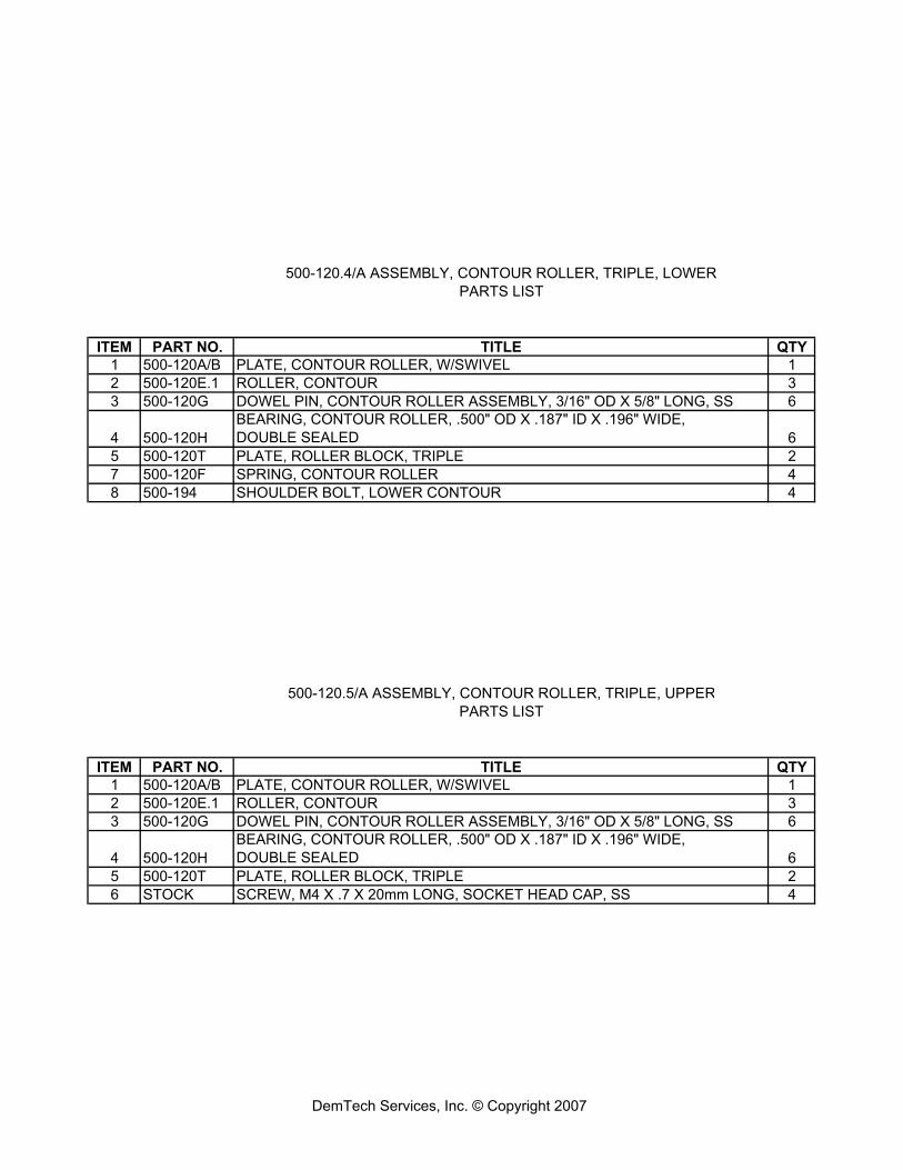
500-120.4/A ASSEMBLY, CONTOUR ROLLER, TRIPLE, LOWERPARTS LIST
ITEM PART NO. TITLE QTY1 500-120A/B PLATE, CONTOUR ROLLER, W/SWIVEL 12 500-120E.1 ROLLER, CONTOUR 33 500-120G DOWEL PIN, CONTOUR ROLLER ASSEMBLY, 3/16" OD X 5/8" LONG, SS 6
4 500-120HBEARING, CONTOUR ROLLER, .500" OD X .187" ID X .196" WIDE,DOUBLE SEALED 6
5 500-120T PLATE, ROLLER BLOCK, TRIPLE 27 500-120F SPRING, CONTOUR ROLLER 48 500-194 SHOULDER BOLT, LOWER CONTOUR 4
500-120.5/A ASSEMBLY, CONTOUR ROLLER, TRIPLE, UPPERPARTS LIST
ITEM PART NO. TITLE QTY1 500-120A/B PLATE, CONTOUR ROLLER, W/SWIVEL 12 500-120E.1 ROLLER, CONTOUR 33 500-120G DOWEL PIN, CONTOUR ROLLER ASSEMBLY, 3/16" OD X 5/8" LONG, SS 6
4 500-120HBEARING, CONTOUR ROLLER, .500" OD X .187" ID X .196" WIDE,DOUBLE SEALED 6
5 500-120T PLATE, ROLLER BLOCK, TRIPLE 26 STOCK SCREW, M4 X .7 X 20mm LONG, SOCKET HEAD CAP, SS 4
DemTech Services, Inc. © Copyright 2007