Embed Size (px)
Citation preview

Model Introduction Training For Approved Motor Body Repairers
Opel Astra K

3
Contents
Overview
Body
Technical
This introduction manual highlights the design and function of new vehicle models.
The introduction manual is not a repair manual!All values given are intended as a guideline only.
Some vehicle pictures may be overseas specification.
For body repair work, always refer to the current body repair manual.
Restraint System
Astra
4
Overview
Introduction
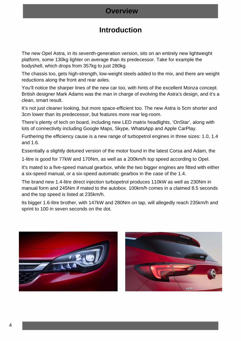
The new Opel Astra, in its seventh-generation version, sits on an entirely new lightweight platform, some 130kg lighter on average than its predecessor. Take for example the bodyshell, which drops from 357kg to just 280kg.The chassis too, gets high-strength, low-weight steels added to the mix, and there are weight reductions along the front and rear axles.You’ll notice the sharper lines of the new car too, with hints of the excellent Monza concept. British designer Mark Adams was the man in charge of evolving the Astra’s design, and it’s a clean, smart result.It’s not just cleaner looking, but more space-efficient too. The new Astra is 5cm shorter and 3cm lower than its predecessor, but features more rear leg-room.There’s plenty of tech on board, including new LED matrix headlights, ‘OnStar’, along with lots of connectivity including Google Maps, Skype, WhatsApp and Apple CarPlay.Furthering the efficiency cause is a new range of turbopetrol engines in three sizes: 1.0, 1.4 and 1.6.
Essentially a slightly detuned version of the motor found in the latest Corsa and Adam, the
1-litre is good for 77kW and 170Nm, as well as a 200km/h top speed according to Opel.
It's mated to a five-speed manual gearbox, while the two bigger engines are fitted with either a six-speed manual, or a six-speed automatic gearbox in the case of the 1.4.
The brand new 1.4-litre direct injection turbopetrol produces 110kW as well as 230Nm in manual form and 245Nm if mated to the autobox. 100km/h comes in a claimed 8.5 seconds and the top speed is listed at 235km/h.
Its bigger 1.6-litre brother, with 147kW and 280Nm on tap, will allegedly reach 235km/h and sprint to 100 in seven seconds on the dot.

5
Colours
Overview
Solid
Metallic
Switchblade Silver Carbon FlashMagnetic Silver
Bronze Brown
Emerald GreenGranite GreyDeep Sky Blue
Dark CaramelAsteroid Grey
Royal Blue Power RedSummit White

6
SPECIFICATIONS
Overview
Category 1.0T 1.4T 1.6T
Engine
Cylinders 3 4 4
Power 77kW 110kW 147kW
Torque 170Nm 230Nm 280Nm
Transmission Manual Man/Auto Manual
Front & Rear Disc Std Std Std
ABS Std Std Std

7
Dimensions
Overview

8
VIN Number
Rims
Essentia: 16’’ Steel wheel6.5J x 16
Tyres 205/55 R16Code PWN
Sport/Plus: 18’’ Aloy wheel7.5J x 18
Tyres 225/40 R18Code 5PC
Enjoy: 17’’ Alloy wheel7.5J x 17
Tyres 225/45 R17Code RM6
Overview
9
Overview
Intellilux LED Matrix Headlights
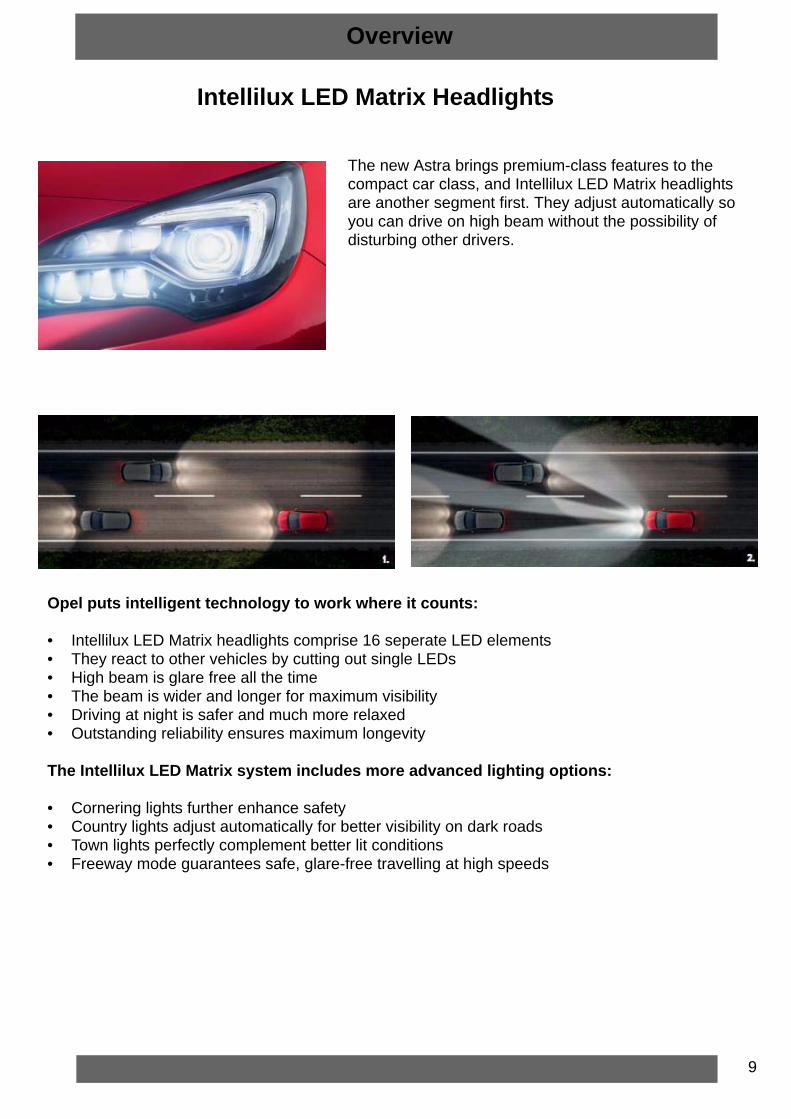
The new Astra brings premium-class features to the compact car class, and Intellilux LED Matrix headlights are another segment first. They adjust automatically so you can drive on high beam without the possibility of disturbing other drivers.
Opel puts intelligent technology to work where it counts:
• Intellilux LED Matrix headlights comprise 16 seperate LED elements• They react to other vehicles by cutting out single LEDs• High beam is glare free all the time• The beam is wider and longer for maximum visibility• Driving at night is safer and much more relaxed• Outstanding reliability ensures maximum longevity
The Intellilux LED Matrix system includes more advanced lighting options:
• Cornering lights further enhance safety• Country lights adjust automatically for better visibility on dark roads• Town lights perfectly complement better lit conditions• Freeway mode guarantees safe, glare-free travelling at high speeds

10
The Opel Eye safety camera helps prevent collisions, speeding tickets and much more.It’s one of the most sophisticated assistance systems ever engineered in a car.
• Opel Eye is a system of advanced safety features• This camera-based system acts as an extra lookout• Continuous automatic assistance helps drivers stay vigilant• Active Lane Assist prevents unnecessary warnings
Overview
Opel Eye
1. Forward Collision Alert Gives you an audible and visible signal if you approach slower vehicles too fast from behind. To avoid rear-end collisions, up to speeds of 60 km/h the system automatically starts braking itself. The new Reflective LED windscreen display provides an extra level of safety with an additional warning in the driver’s field of view.2. Active Lane Keep Assist Warning signals protect against unintentional gradual drifting and the steering wheel even pushes back gently – if you start moving out of your lane without signalling. The real genius of this system? It won’t sound an alarm when you don’t need one. For example, if you have to swerve hard to avoid an obstacle.3. Traffic Sign Assist. This advanced sign-detection system displays speed limits and other traffic signs and even recognises temporary electronic signage.

11
Shift Lock Manual Release (Automatic)
The Automatic transmission has an electric shift lock. The key must be in the ON/Run position and the brake pedal pressed, so the transmission selector lever can be moved from the P(Park) or the N(Neutral) position. If the battery has lost power, the selector cannot be moved unless the shift lock manual release is engaged manually.
Shift Lever Controls (Manual)
(1) Manual Transmission Shift Lever and Selector Lever Cable(2) Transmission Shift Lever Cable Adjuster(3) Selector Lever Cable Adjuster(4) Control Lever Release Pawl(5) Control Lever Knob(6) Transmission Control(7) Selector and Shift Lever Cable Bracket
Technical
12
Front Suspension
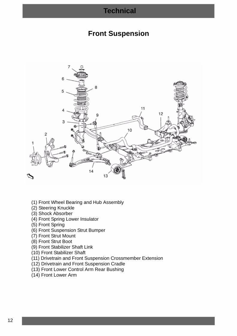
(1) Front Wheel Bearing and Hub Assembly(2) Steering Knuckle(3) Shock Absorber(4) Front Spring Lower Insulator(5) Front Spring(6) Front Suspension Strut Bumper(7) Front Strut Mount(8) Front Strut Boot(9) Front Stabilizer Shaft Link(10) Front Stabilizer Shaft(11) Drivetrain and Front Suspension Crossmember Extension(12) Drivetrain and Front Suspension Cradle(13) Front Lower Control Arm Rear Bushing(14) Front Lower Arm
Technical

13
(1) Rear Wheel Bearing and Hub Assembly(2) Rear Brake Caliper Bracket(3) Rear Axle Bracket Assembly(4) Rear Spring Insulator(5) Rear Spring(6) Rear Shock Absorber(7) Rear Axle(8) Rear Suspension Latch Link(9) Center Pivot Ball Joint(10) Equilizer Beam Support
Rear Suspension
Technical

14
Astra K
Axle with Watts Link
• Available on specific vehicle and engine combinations• New A-bushing concept/position to get excellent ride comfort• Optimised Watts link concept• Delivers all of the advantages of multi-link rear suspension without any of the
complexities
Astra J
Technical

15
Belt Driven Electric Power Steering
(1) Control module and motor
(2) Sensor Location
(3) Belt case
• Optimized in regards “direct steering feel” and mass• Reduced amount of power needed at any speed• Smooth Road Shake Compensation (SRSC)• Drift Pull Compensation (DPC)• Advanced Active Return• Supports optional driver assistance features:
Lane Keeping Assist (LKA)Stop Start capability
Steering Belt
Technical

16
Body Structure
Body
Number Part Material Material Thickness
1 Front End Upper Tie Bar Mild Steel
1.1 Radiator Upper Support Mild Steel
1.2 Hood Adjust Front Bumper Mild Steel 1.2
2 Front End Upper Tie Bar Extension High Strength Low Alloy Steel
3 Front End Upper Tie Bar Bracket High Strength Low Alloy Steel 2.1
4 Drivetrain and Front Suspension Frame Front Support
see 5.1 and 5.2
5 Front Compartment Side Rail

17
Body
Number Part Material Material Thickness
5.1 Drivetrain and Front Suspension Frame Support Outer
Mild Steel 1.2
5.2 Drivetrain and Front Suspension Frame Support
High Strength Low Alloy Steel 1.2
5.3 Front Compartment Side Rail Dual Phase Steel 1.9
5.4 Front Compartment Side Rail High Strength Low Alloy Steel 1.9
5.5 Drivetrain and Front Suspension Frame Support
High Strength Low Alloy Steel 2.0
5.6 Front Compartment Side Rail Closeout Panel
High Strength Low Alloy Steel 1.2
5.7 Engine Mount Bracket Mild Steel 1.8
5.8 Dash Panel Front Lower Cross Bar High Strength Low Alloy Steel 1.5
5.9 Front Compartment Side Rail Plate High Strength Low Alloy Steel 3.0
6 Front Compartment Upper Side Rail Fender Bracket-Mild SteelRail Front-High Strength Low Alloy SteelRail Rear-Dual Phase Steel
1.00.7
1.8
6.1 Front Fender Bracket Mild Steel 1.0
7 Front Wheelhouse Panel Brace High Strength Low Alloy Steel 1.0
8 Front Wheelhouse Panel
8.1&8.2 Headlamp Mount Panel High Strength Low Alloy Steel 0.8
8.3 Front Compartment Side Rail High Strength Low Alloy Steel 1.3
8.4 Front Wheelhouse Panel Support High Strength Low Alloy Steel 1.2
8.5 Front Wheelhouse Panel Brace High Strength Low Alloy Steel 1.0
8.6 Front Wheelhouse Panel High Strength Low Alloy Steel 1.2
8.7 Front Suspension Strut Housing High Strength Low Alloy Steel 2.4
9 Front Compartment Rail Closeout Panel High Strength Low Alloy Steel 1.2
10 Body Hinge Pillar Outer Panel Ultra High Strength Steel 1.0
50 Dash Panel Lower Extension Mild Steel 0.85
51 Dash Panel Extension Mild Steel 0.8
52 Body Hinge Pillar Inner Panel Ultra High Strength Steel 1.1
53 Dash Panel Front Lower Cross Bar Mild Steel 1.0
54 Front Compartment Rear Side Rail Ultra High Strength Steel 2.0

18
Body
Body Side
Number Part Material Material Thickness
10 Body Hinge Pillar Outer Panel Reinforcement
Ultra High Strength Steel
1.0
11 Body Hinge Pillar Outer Panel Mild Steel 0.65
12 Rocker Outer Panel Mild Steel 0.65
13 Center Pillar - Outer Mild Steel 0.65
14 Center Pillar Reinforcement: Ultra High Strength SteelInner: Dual Phase Steel
1.3
1.0
15 Quarter Outer Panel Mild Steel 0.65
16 Body Side Outer Panel Extension Mild Steel 0.65
17 Body Side Tail Lamp Pocket Mild Steel 1.1
19
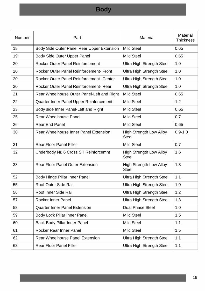
Body
Number Part Material Material Thickness
18 Body Side Outer Panel Rear Upper Extension Mild Steel 0.65
19 Body Side Outer Upper Panel Mild Steel 0.65
20 Rocker Outer Panel Reinforcement Ultra High Strength Steel 1.0
20 Rocker Outer Panel Reinforcement- Front Ultra High Strength Steel 1.0
20 Rocker Outer Panel Reinforcement- Center Ultra High Strength Steel 1.0
20 Rocker Outer Panel Reinforcement- Rear Ultra High Strength Steel 1.0
21 Rear Wheelhouse Outer Panel-Left and Right Mild Steel 0.65
22 Quarter Inner Panel Upper Reinforcement Mild Steel 1.2
23 Body side Inner Panel-Left and Right Mild Steel 0.65
25 Rear Wheelhouse Panel Mild Steel 0.7
26 Rear End Panel Mild Steel 0.65
30 Rear Wheelhouse Inner Panel Extension High Strength Low Alloy Steel
0.9-1.0
31 Rear Floor Panel Filler Mild Steel 0.7
32 Underbody Nr. 6 Cross Sill Reinforcemnt High Strength Low Alloy Steel
1.6
33 Rear Floor Panel Outer Extension High Strength Low Alloy Steel
1.3
52 Body Hinge Pillar Inner Panel Ultra High Strength Steel 1.1
55 Roof Outer Side Rail Ultra High Strength Steel 1.0
56 Roof Inner Side Rail Ultra High Strength Steel 1.2
57 Rocker Inner Panel Ultra High Strength Steel 1.3
58 Quarter Inner Panel Extension Dual Phase Steel 1.0
59 Body Lock Pillar Inner Panel Mild Steel 1.5
60 Back Body Pillar Inner Panel Mild Steel 1.1
61 Rocker Rear Inner Panel Mild Steel 1.5
62 Rear Wheelhouse Panel Extension Ultra High Strength Steel 1.1
63 Rear Floor Panel Filler Ultra High Strength Steel 1.1

20
Rear End
Body
Number Part Material Material Thickness
26 Rear End Panel Mild Steel 0.65
27 Rear Floor Rear Panel High Strength Low Alloy Steel 0.8
28 Floor Panel Number 5 Cross Bar High Strength Low Alloy Steel 0.8-1.1-1.4
29 Battery Tray Mild Steel 0.7

21
Body
Number Part Material Material Thickness
30 Rear Wheelhouse Inner Panel Extension High Strength Low Alloy Steel
0.9-1.0
31 Rear Floor Panel Filler Mild Steel 0.7
32 Underbody Number 6 Cross Sill High Strength Low Alloy Steel
1.6
33 Rear Floor Panel Outer Extension High Strength Low Alloy Steel
1.3
34 Underbody Rear Side Rail Extension High Strength Low Alloy Steel
2.5
35 Underbody Rear Side Rail Reinforcement High Strength Low Alloy Steel
2.5
36 Floor Panel Number 5 Cross Bar Extension Mild Steel 1.5
37 Underbody Rear Side Rail Dual Phase Steel 1.3
64 Rear Wheelhouse Panel Reinforcement Mild Steel 0.7
65 Underbody Rear Side Front Rail Ultra High Strength Steel 1.8
66 Underbody Number 5 Cross Sill High Strength Low Alloy Steel
1.7
67 Rear Floor Front Panel Mild Steel 0.65

22
Body
Roof
Number Part Material Material Thickness
37 Roof Panel Mild Steel 0.65
38 Roof Front Header Panel Upper: High Strength Low Alloy SteelLower: Dual Phase SteelExtension: High Strength Low Alloy Steel
0.7
1.01.0
39 Roof Panel Number 2 Bow Ultra High Strength Steel 0.75
40 Roof Panel Number 3 Bow High Strength Low Alloy Steel
0.65

23
Body
Number Part Material Material Thickness
41 Roof Rear Header Panel Mild Steel 0.65
22 Quarter Inner Panel Upper Reinforcement Mild Steel Upper: 1.2Lower: 0.6
55 Roof Outer Side Rail Ultra High Strength Steel 1.0
56 Roof Inner Side Rail Ultra High Strength Steel 1.2
59 Body Lock Pillar Inner Panel Mild Steel 1.5

24
Floor
Body
Number Part Material Material Thickness
28 Floor Panel Number 5 Cross Bar High Strength Low Alloy Steel
0.8-1.1-1.4
29 Battery Tray Mild Steel 0.7Side: 1.4
42 Underbody Front Side Rail Outrigger Dual Phase Steel Front: 1.0Rear: 1.5
50 Dash Panel Lower Extension Mild Steel 0.85
52 Body Hinge Pillar Inner Panel Ultra High Strength Steel 1.1
54 Front Compartment Rear Side Rail Ultra High Strength Steel 2.0
68 Drivetrain and Front Suspension Frame Rear Support
Mild Steel 2.5

25
Front Bumper Impact Bar Replacement
Body
(1) Front Bumper Impact Bar Bolt [x8](2) Front Bumper Impact Bar

26
Front Compartment Side Rail Replacement
Body
Locate and mark all factory welds (1)Drill out all factory welds
Locate and mark all factory welds (1)Drill out all factory welds
Removal
27
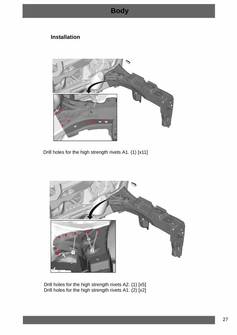
Installation
Body
Drill holes for the high strength rivets A1. (1) [x11]
Drill holes for the high strength rivets A2. (1) [x5]Drill holes for the high strength rivets A1. (2) [x2]

28
Body
Apply structural adhesive GL02. (1)
Apply tape (1) to the front compartment rear side rail as shown to prevent shunt circuit.Apply structural adhesive GL02. (2)
Apply structural adhesive GL02. (1)

29
Front Compartment Side Rail Install:• High Strength Rivet A1 (2) [x11]• 8 Spot welds (3)Remove tape from the front compartment rear side rail
Body
Front Compartment Front Side Rail Install:High Strength Rivet A2 (1) [x5]High Strength Rivet A1 (2) [x2]Apply the sealers and anti-corrosion materials to the repair area as necessary.
30
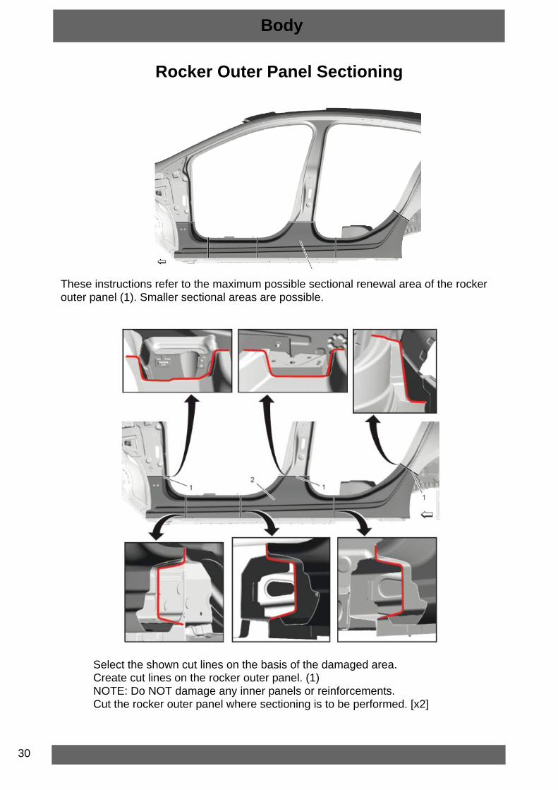
Rocker Outer Panel Sectioning
Body
These instructions refer to the maximum possible sectional renewal area of the rocker outer panel (1). Smaller sectional areas are possible.
Select the shown cut lines on the basis of the damaged area.Create cut lines on the rocker outer panel. (1)NOTE: Do NOT damage any inner panels or reinforcements.Cut the rocker outer panel where sectioning is to be performed. [x2]

31
Body
Locate and mark all factory welds. (1) at Rocker Outer Panel (2)Drill out all factory welds.Detach structural adhesive at the area of the rear wheelhouse.Open wheelhouse flanging.Remove damaged part of the rocker outer panel.
Drill holes for waterproof rivets B1 (1) according to sectional replacement of the rocker outer panel (2).• Lower body hinge pillar - 6 holes for waterproof rivets B1• Rocker outer panel front - 8 holes for waterproof rivets B1• Lower center pillar - 8 holes for waterproof rivets B1• Rear outer panel front - 8 holes for waterproof rivets B1

32
Body
Apply Structural adhesive GL02. (1)Apply sealant (2).Position rocker panel on vehicle.
Install the rocker outer panel (1).• Lower body hinge pillar - 6 spotwelds and 6 waterproof rivets B1• Rocker outer panel front - 12 spotwelds and 8 waterproof rivets B1• Lower center pillar - 8 spotwelds and 8 waterproof rivets B1• Rear outer panel front - 15 spotwelds and 8 waterproof rivets B1
33
Body
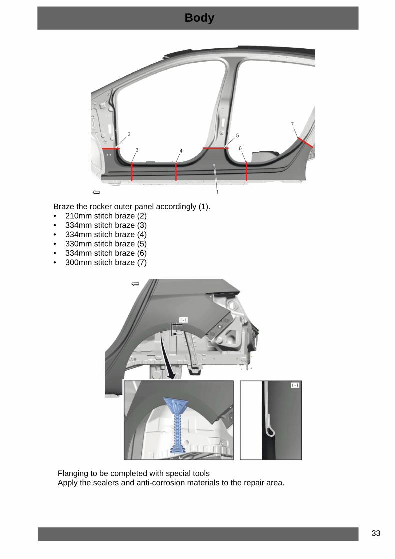
Braze the rocker outer panel accordingly (1).• 210mm stitch braze (2)• 334mm stitch braze (3)• 334mm stitch braze (4)• 330mm stitch braze (5)• 334mm stitch braze (6)• 300mm stitch braze (7)
Flanging to be completed with special toolsApply the sealers and anti-corrosion materials to the repair area.
34
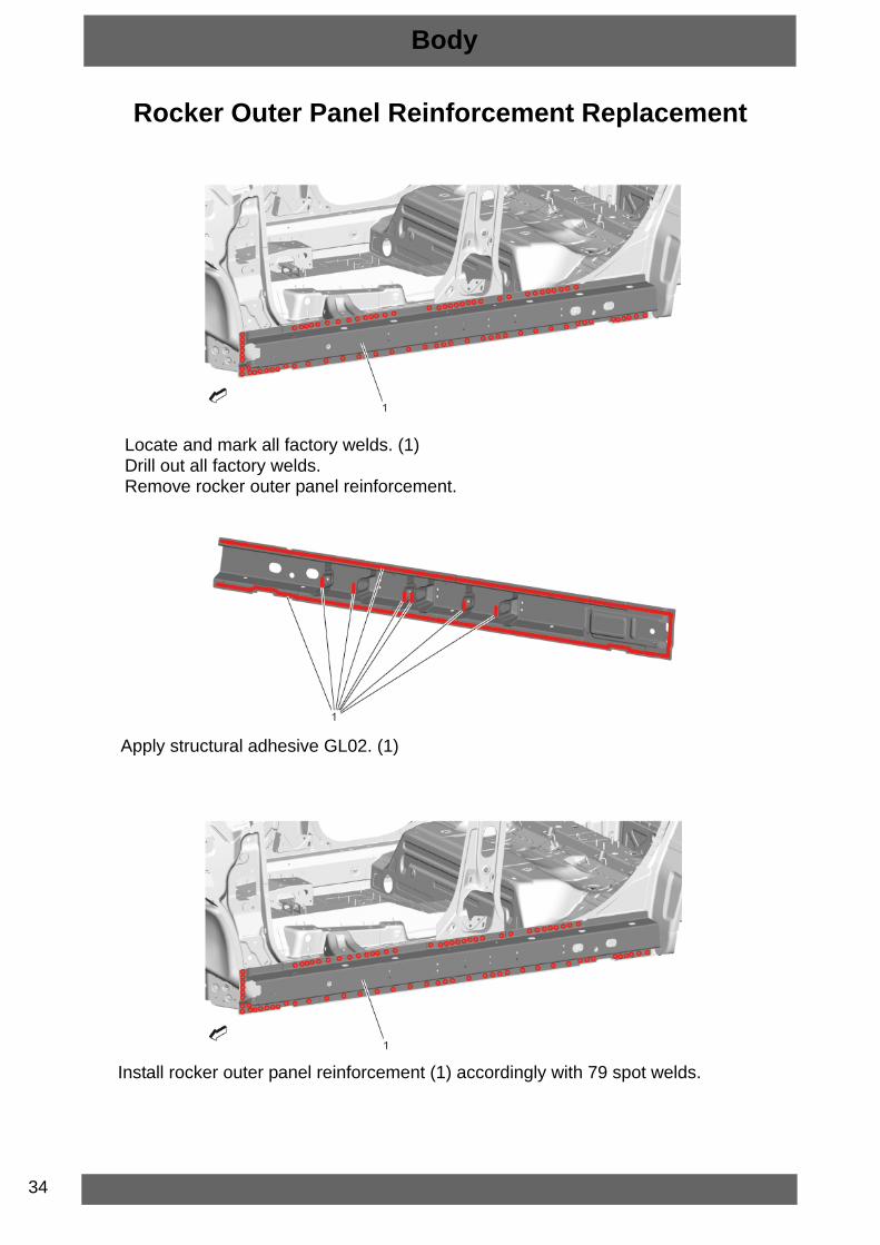
Rocker Outer Panel Reinforcement Replacement
Body
Locate and mark all factory welds. (1)Drill out all factory welds.Remove rocker outer panel reinforcement.
Apply structural adhesive GL02. (1)
Install rocker outer panel reinforcement (1) accordingly with 79 spot welds.

35
Center Pillar Replacement
Body
Locate and mark all the necessary factory welds of the center pillar reinforcement (1).Drill out all factory welds.Remove center pillar reinforcement.
Locate and mark all the necessary factory welds of the center pillar inner panel (1).Drill out all factory welds.Remove the center pillar inner panel.
36
Body
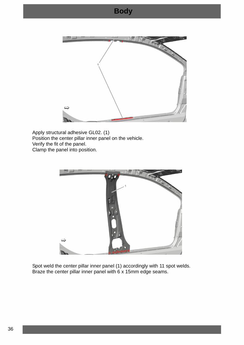
Apply structural adhesive GL02. (1)Position the center pillar inner panel on the vehicle.Verify the fit of the panel.Clamp the panel into position.
Spot weld the center pillar inner panel (1) accordingly with 11 spot welds.Braze the center pillar inner panel with 6 x 15mm edge seams.

37
Body
Drill holes for the high strength rivets A2. (1) [x20]Remove the center pillar reinforcement.
Apply structural adhesive GL02 (1) to door striker anchor plate (2).Position the door striker anchor plate (1) on the center pillar reinforcement service part (2).
38
Body
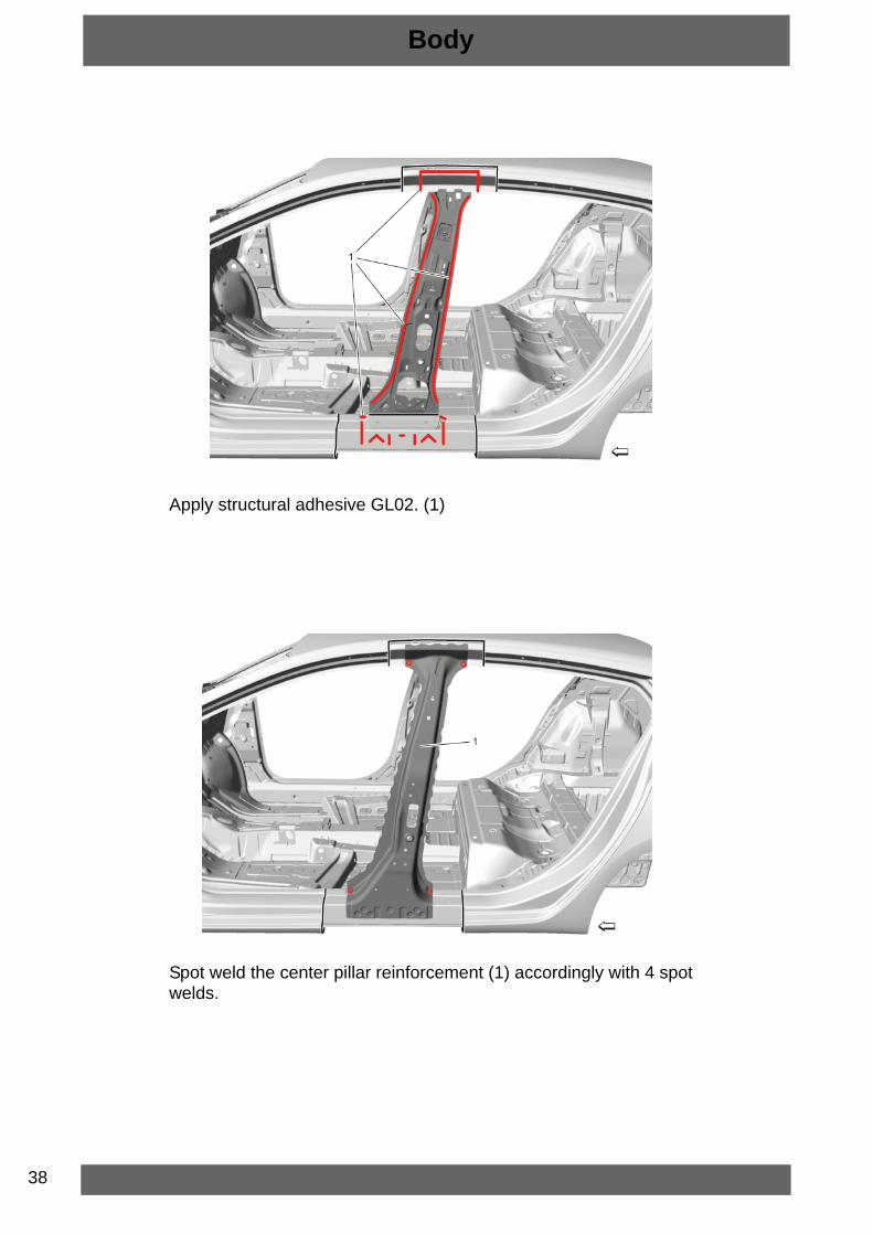
Apply structural adhesive GL02. (1)
Spot weld the center pillar reinforcement (1) accordingly with 4 spot welds.
39
Body
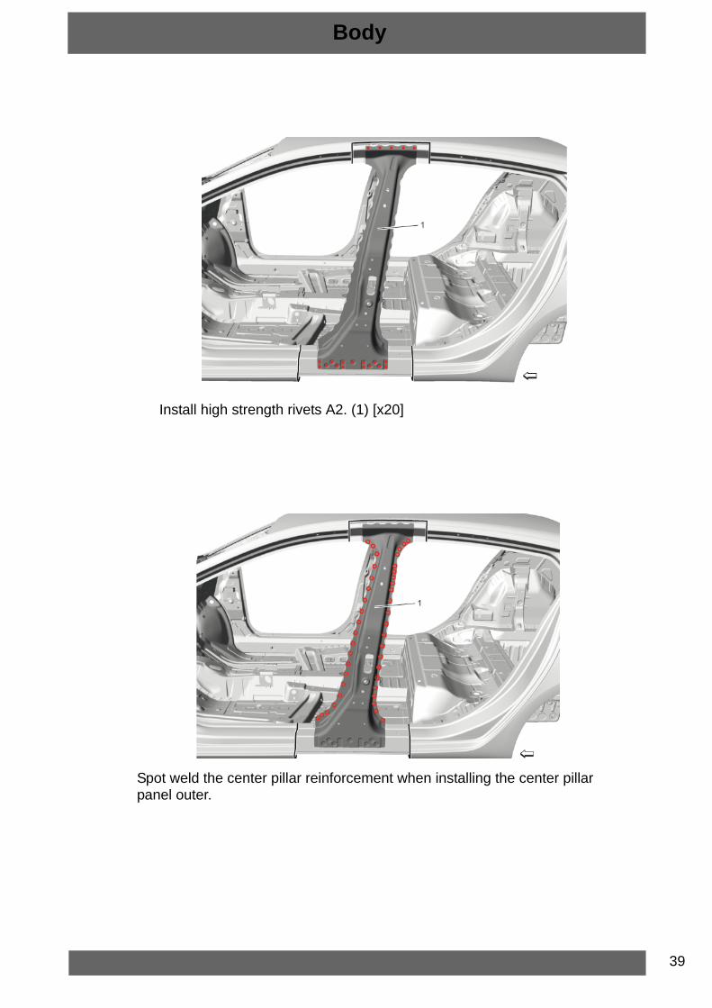
Install high strength rivets A2. (1) [x20]
Spot weld the center pillar reinforcement when installing the center pillar panel outer.

40
Quarter Outer Panel Replacement
Body
Create cut lines (1) on the quarter outer panel (2).NOTE: Do NOT damage any inner panels or reinforcements.Cut the quarter outer panel.
Locate and mark all factory welds (1) of the quarter outer panel (2).Drill out all factory welds.

41
Locate and mark all factory welds (1) of the quarter outer panel (2).Drill out all factory welds.Open the wheelhouse flanging and remove quarter panel.
Cut the quarter panel (1) in corresponding locations to fit the remaining original panel.
Body

42
Drill 11 holes (1) for waterproof rivets B1 to the quarter outer panel.Clean and prepare the attaching surfaces for brazing, riveting and spot welding.
Apply structural adhesive GL02. (1)Apply window adhesive GL01. (3) (2)
Body

43
Right side only: Apply sealant (1) to body side inner panel filler.
Install the quarter panel (1) accordingly.• 370mm braze seam (2)• 3 waterproof rivets B1 (3)• 10 spot welds (4)• 8 waterproof rivets B1 and 1 spot weld (5)• 334mm braze seam (6)• 32 spot welds (7)
Body

44
Install the quarter panel (1) accordingly.22 spot welds (2)
Pre-flange the wheelhouse flange.Finish closing the wheelhouse flange.Apply the sealers and anti-corrosion materials to the repair area as necessary.
Body

45
Front Bumper Lower Impact Bar Replacement
(1) Front Bumper Lower Impact Bar Bolt [x4](2) Front Bumper Lower Impact Bar
Body

46
Front Bumper Fascia Replacement
(1) Front Bumper Fascia Upper Bolt (1) - Remove [x6]
(1) Front Bumper Fascia Upper Bolt (1) - Remove [x2](2) Front Wheelhouse Liner Bolt (2) - Remove [x6]
Body

47
Pull the Front Bumper Fascia (1) carefully outwards and use a plastic tool in order to release the retaining tabs from the front bumper fascia outer guides.
Disconnect all electrical connectors.Remove Front Bumper Fascia (1).
Body

48
Headlamp Replacement (Halogen)
(1) Headlamp Bolt [x4](2) Headlamp
Headlamp Replacement (LED/Matrix)
(1) Headlamp Bolt [x4](2) Headlamp
Body
49
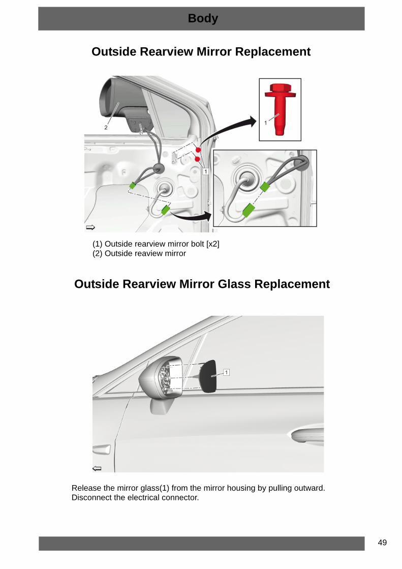
Outside Rearview Mirror Replacement
(1) Outside rearview mirror bolt [x2](2) Outside reaview mirror
Outside Rearview Mirror Glass Replacement
Release the mirror glass(1) from the mirror housing by pulling outward.Disconnect the electrical connector.
Body
50
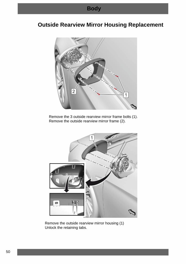
Outside Rearview Mirror Housing Replacement
Remove the 3 outside rearview mirror frame bolts (1).Remove the outside rearview mirror frame (2).
Remove the outside rearview mirror housing (1)Unlock the retaining tabs.
Body
51
Body
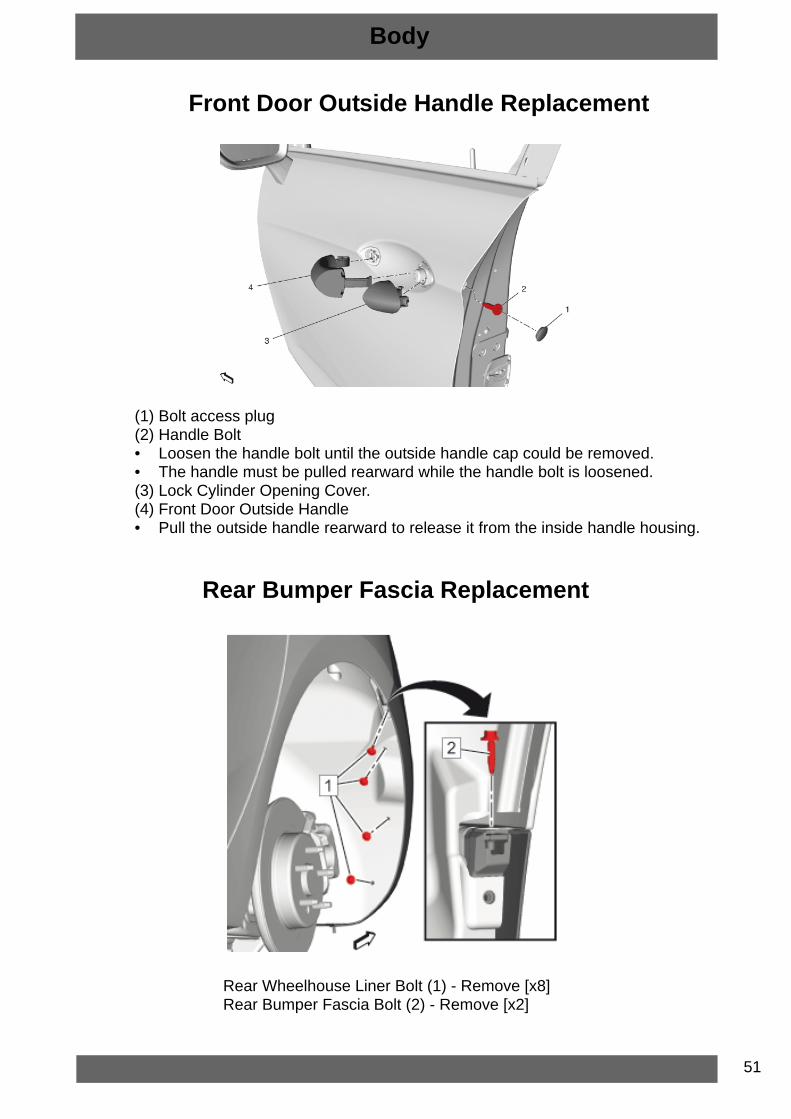
Front Door Outside Handle Replacement
(1) Bolt access plug(2) Handle Bolt• Loosen the handle bolt until the outside handle cap could be removed.• The handle must be pulled rearward while the handle bolt is loosened.(3) Lock Cylinder Opening Cover.(4) Front Door Outside Handle• Pull the outside handle rearward to release it from the inside handle housing.
Rear Bumper Fascia Replacement
Rear Wheelhouse Liner Bolt (1) - Remove [x8]Rear Bumper Fascia Bolt (2) - Remove [x2]

52
Body
Rear Bumper Fascia Bolt (1) - Remove [x2]Rear Bumper Fascia Lower Bolt (2) - Remove [x2]
Pull the rear bumper fascia (1) carefully outwards and use a plastic tool in order to release the retaining tabs from the rear bumper fascia outer guides.

53
Body
Pull the rear bumper fascia carefully outwards and use a plastic tool in order to release the retaining tabs from the rear bumper fascia guides (1).Disconnect all electrical Connectors.
Rear Bumper Fascia (1) - Remove

54
Body
Tail Lamp Replacement
(1) Tail Lamp Nut(2) Tail Lamp
55
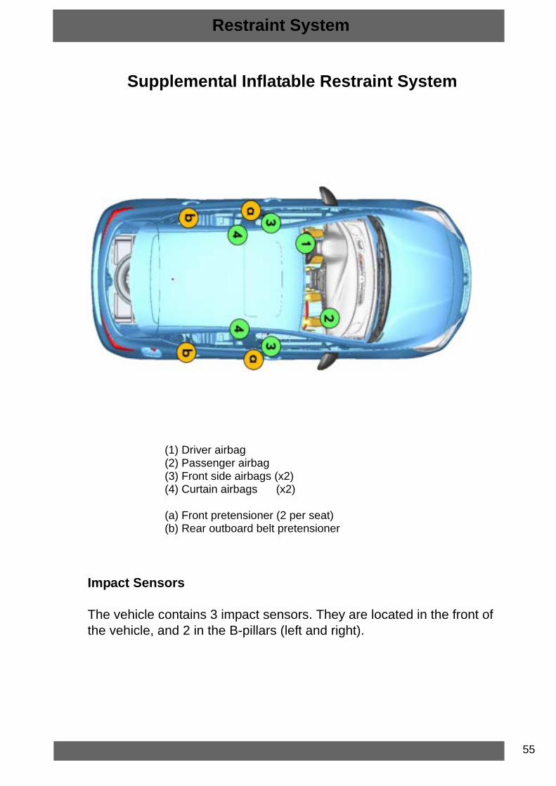
Supplemental Inflatable Restraint System
(1) Driver airbag(2) Passenger airbag(3) Front side airbags (x2)(4) Curtain airbags (x2)
(a) Front pretensioner (2 per seat)(b) Rear outboard belt pretensioner
Impact Sensors
The vehicle contains 3 impact sensors. They are located in the front of the vehicle, and 2 in the B-pillars (left and right).
Restraint System

56
Driver Airbag Module Removal
• Lower the steering column and move to the Maximum rear end position.• Turn the steering wheel so that the whole is at the top.• Insert a screwdriver or equivalent tool (2) through the access opening and push
the spring fastener (1) inward to release the steering wheel inflator from the steering wheel.
• Turn the steering wheel 180 degrees to access the second whole and repeat the procedure.
• Disconnect the electrical connector and remove airbag module.
NOTE: Always disable the SIR system before performing any work on the system.
Restraint System

57
Passenger Airbag Module Removal
NOTE: Always disable the SIR system before performing any work on the system.
• Unlock the retaining tabs [x6] on the module(1).
Restraint System

58
Front Seat Side Airbag
NOTE: Always disable the SIR system before performing any work on the system.
(1) Front Seat Side Airbag fastener [x2](2) Front Seat Side Airbag
Restraint System

59
Roof Curtain Airbag
NOTE: Always disable the SIR system before performing any work on the system.
Roof Curtain Airbag Retainer [x2]Roof Curtain Airbag Fastener [x5]Roof Curtain Airbag ClipRoof Curtain Airbag Electrical ConnectorRoof Curtain Airbag [Left and Right]
Restraint System
60
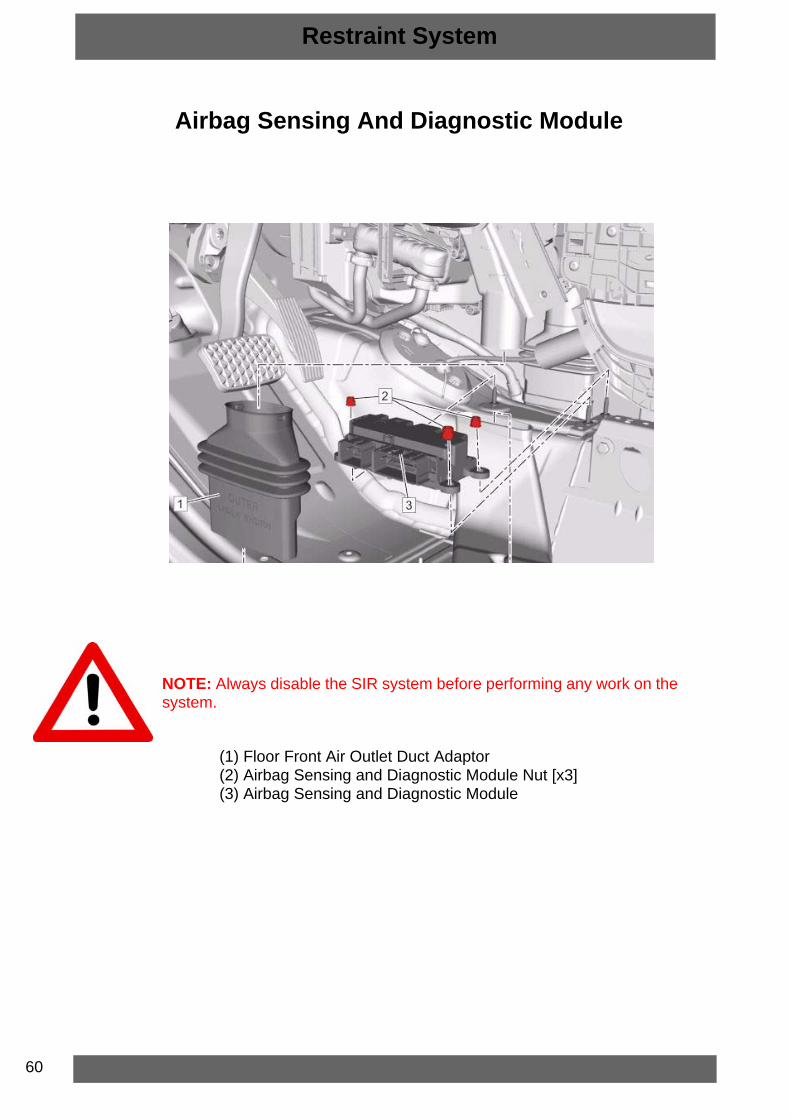
Airbag Sensing And Diagnostic Module
NOTE: Always disable the SIR system before performing any work on the system.
(1) Floor Front Air Outlet Duct Adaptor(2) Airbag Sensing and Diagnostic Module Nut [x3](3) Airbag Sensing and Diagnostic Module
Restraint System

Notes

Notes