Embed Size (px)
Citation preview
1
NONLINEAR FINITE ELEMENT ANALYSIS OF FOUR-PILE CAPS
SUPPORTING COLUMNS SUBJECTED TO GENERIC LOADING
Rafael Alves de Souza1
Associate Professor, Departamento de Engenharia Civil, Universidade Estadual de Maringá, Av. Colombo, 5790, Bloco C67, CEP 87020-900, Maringá - PR, Brazil.
e-mail: [email protected]
Daniel Alexander Kuchma Assistant Professor, Department of Civil and Environmental Engineering, University of Illinois at Urbana-Champaign, 2114 Newmark Laboratory,
205 N. Mathews Ave., 61801, Urbana - IL, USA e-mail: [email protected]
JungWoong Park
Post-doc researcher, Department of Civil and Environmental Engineering, University of Illinois at Urbana-Champaign, 2111 Newmark Laboratory,
205 N. Mathews Ave., 61801, Urbana - IL, USA e-mail: [email protected]
Túlio Nogueira Bittencourt
Associate Professor, Departamento de Engenharia de Estruturas e Fundações, Escola Politécnica da Universidade de São Paulo, Av. Prof. Almeida Prado, trav.2, n.271,
Cidade Universitária, CEP 05508-900, São Paulo - SP, Brazil. e-mail: [email protected]
Abstract: The paper presents the development of an adaptable strut-and-tie model that can be
applied to the design or analysis of four-pile caps that support axial compression and biaxial
flexure from a supported rectangular column. Due to an absence of relevant test data, the model
is validated using non-linear finite element analyses (NLFEA). The results indicate that the use
of the proposed model would lead to safe and economical designs. The proposed model can be
easily extended to any number of piles, providing a rational procedure for the design of wide
range of pile caps.
1 Author to whom correspondence and proofs should be sent

2
1. INTRODUCTION
In traditional design practice, pile caps are assumed to acts as beams spanning between
piles. The depth of a cap is then selected to provide adequate shear capacity and the required
amount of longitudinal reinforcement is calculated using engineering beam theory. Quite recently,
methods for the design of pile cap have been developed that are based on the strut-and-tie
approach. These include the methods in the Canadian CSA Code (1984), by Schlaich et al.
(1987), in the AASHTO LRFD code (1994), in the Spanish concrete code EHE (1999), by
Reineck (2002), and in the American ACI318 building code (2002). These methods assume that
an internal load resisting truss, so-called strut-and-tie model, carries the forces through the pile
cap in which concrete compressive struts act between the column and piles and steel ties
(reinforcement) act between piles.
Results of elastic analyses, as example that one obtained by Iyer & Sam (1992),
illustrate that there is a complex state of straining in these three-dimensional pile caps and that
the Strut-and-Tie Theory provides a rational basis for design. Adebar et al. (1990), Adebar &
Zhou (1996), Bloodworth et al (2003) and Caves & Fenton (2004) have provided experimental
evidence demonstrating that the use of sectional approaches based on engineering beam theory
are not appropriate for the design of pile caps. As further illustrated in the research conducted by
Blévot & Fremy (1967), Clarke (1972), Suzuki et al (1998, 1999, 2000) and Suzuki & Otsuki
(2002), many pile caps designed to fail in flexure by engineering beam theory have been reported
to fail in shear. This is highly undesirable behavior as there is neither warning cracks nor
pronounced deformations before these types of brittle shear failures occur.
These unexpected shear failures can be explained in two ways. Firstly, engineering
beam theory was originally developed for structural elements with significant deformation
3
capacity. As a consequence, if this theory is applied to elements with limited deformation
capacity such as pile caps, the calculated effective depth will tend to overestimate the concrete
contribution from shear. Secondly, engineering beam theory usually leads to more longitudinal
reinforcement than would be calculated by using a strut-and-tie approach, and for the specific
situation of four-pile caps, Clarke (1972) concluded that this difference can be higher than 20%.
Consequently, pile caps designed using engineering beam theory have a tendency to be over
reinforced and as consequence, shear failures may occur as a result of longitudinal splitting of
compression struts before yielding of the longitudinal reinforcement.
Although the strut-and-tie approach provides a more rational basis for the design of
pile caps, it is only commonly applied for the design of simple pile caps such as pile caps
supporting square columns subjected to axial load. This is believed to be due to the complexity
and uncertainties as to the appropriate strut-and-tie model to use for more complex loading
conditions. Thus, designers have chosen to rely on the use of engineering beam theory for the
design of even slightly more complex pile caps, including four-pile caps that support axial
compression and biaxial flexure from a single rectangular column.
To address the situation of pile caps supporting columns under general situation (axial
compression and biaxial flexure), an adaptable strut-and-tie model for four-pile caps is proposed
in this paper. Unfortunately there is no experimental test data on the performance of this type of
four-pile caps. Thus, non-linear finite element analysis (NLFEA) has been applied to make the
best possible prediction of the behavior of these pile caps. A NLFEA program was selected for
use that was specifically written for predicting the behavior of a three-dimensional continuum of
structural concrete subjected to a complex state of stress. This program will be validated herein
by available test data. The result of the analyses of four-pile caps supporting axial compression

4
and biaxial flexure from a single column will illustrate the appropriateness of the proposed
model. This model can be further extended for the design of more complex pile caps.
2. AN ADAPTABLE STRUT-AND-TIE MODEL TO THE DESIGN O F FOUR-PILE CAPS
The proposed model is an adaptable 3-dimensional strut-and-tie model, which can be
used for the design or analysis of four-pile caps supporting square or rectangular columns
subjected to the generic loading conditions of axial compression load and biaxial flexure. This
model is presented in Fig. 1. In the proposed model, axial compression forces are taken as
negative, tensile forces are taken as positive, and the net axial load acting from the column on the
pile cap is always compressive.
Fig. 1 – Proposed strut-and-tie model for four-pile caps and positive signal convention for biaxial flexure
The axial compression and biaxial flexure acting on the square or rectangular columns
can be statically substituted by a single compressive axial load, which has the nominal
eccentricities presented in Eqs. (1) and (2):
2
a
N
M-e
k
ky,kx, ±≤= ………………………………………………………………………………(1)

5
2
b
N
Me
k
kx,ky, ±≤= ………………………………………………………………….……………(2)
Nominal reactions of the piles are calculated using Eqs. (3) to (6), and in order to keep
the validity of the proposed model, no tensile piles are permitted in the present formulation:
0sinβ
sinβ
tgθ
tgθRR
A
B
B
AkB,kA, ≤= ……………………………………………………………….........(3)
0
sinβ
cosβ
tgθ
tgθ
cosβ
cosβ
tgθ
tgθ
sinβ
cosβ
tgθ
tgθ
sinβ
sinβ
tgθ
tgθ1
NR
D
B
B
D
C
B
D
C
D
B
B
D
A
B
B
A
kkB, ≤
+++= …...……………………..(4)
0cosβ
cosβ
tgθ
tgθRR
C
D
D
CkD,kC, ≤= …………………………………………………………………….(5)
0sinβ
cosβ
tgθ
tgθRR
D
B
B
DkB,kD, ≤= …………………………………………………………………….(6)
In order to calculate the angles between the idealized struts and ties, it is first necessary
to calculate the projections of struts on the horizontal plane, as show in Eqs. (7) to (10):
2ky,
2kx,A )e(0.5e)e(0.5eL −++= …………………………………………………………...(7)
2ky,
2kx,B )e(0.5e)e(0.5eL −+−= ……………….…………………………………………...(8)
2ky,
2kx,C )e(0.5e)e(0.5eL +++= ……………….…………………………………………...(9)
2ky,
2kx,D )e(0.5e)e(0.5eL ++−= …………… …………………………………………….(10)
The angles between struts and ties can are calculated by Eqs. (11) to (18), as follows:
A
1-A L
dtanθ = ………………………………………………………………………………….(11)
B
1-B L
dtanθ = …………………………………………………………………………………..(12)

6
C
1-C L
dtanθ = ..…………………………………………………………………………………(13)
D
1-D L
dtanθ = ..………………………………………………………………………………...(14)
)e(0.5e
)e(0.5etanβ
ky,
kx,1-A −
+= …..…………………………………………………………………….(15)
)e(0.5e
)e(0.5etanβ
ky,
kx,1-
−−
=B …..…………………………………………………………………….(16)
)e(0.5e
)e(0.5etanβ
kx,
ky,1-
++
=C ………..……………………………………………………………….(17)
)e(0.5e
)e(0.5etanβ
kx,
ky,1-
−+
=D ….…….……………………………………………………………….(18)
Nominal axial forces acting in concrete struts are calculated using Eqs. (19) to (22)
while nominal axial forces acting on steel ties are determined using Eqs. (23) to (26), as follows:
0sin
RC
A
kA,kA, ≤=
θ……………..………………………………………………………………..(19)
0sin
RC
B
kB,kB, ≤=
θ……………...………………………………………………………………..(20)
0sin
RC
C
kC,kC, ≤=
θ……..………………………………………………………………………...(21)
0sin
RC
D
kD,kD, ≤=
θ………….…………………………………………………………………...(22)
0sincosCsincosCT BBkB,AAkA,kAB, ≥−=−= βθβθ …...………………………………………..(23)
0coscosCcoscosCT DDkD,CCkC,kCD, ≥−=−= βθβθ ...………………………………………….(24)
0sincosCcoscosCT CCkC,AAkA,kAC, ≥−=−= βθβθ ……...…………………………………….(25)
7
0sincosCcoscosCT DDkD,BBkB,kBD, ≥−=−= βθβθ ...………………………………………….(26)
Once the nominal forces acting in ties are known, the amount of reinforcement for
each tie can be calculated by applying the necessary safety factors and taking into account the
yielding of the reinforcement, as show in Eqs. (27) to (30):
y
kAB,ABs, f
T A
φγ
= .……………………………………………………………………………….(27)
y
kAC,ACs, f
T A
φγ
= .……………………………………………………………………………….(28)
y
kCD,CDs, f
T A
φγ
= ……….……………………………………………………………………… (29)
y
kBD,BDs, f
T A
φγ
= ………….…………………………………………………………………….(30)
Equations (27) to (30) give the minimum required amount of concentrated
reinforcement for each tie. If biaxial moment is acting on the column, the amount of
reinforcement is expected to be different for the ties. Taking in account the possibility of
inaccurate positioning of these different reinforcements in the field, the largest calculated tie
reinforcement in each direction may be provided for both ties in that direction, as shown in Eqs.
(31) and (32):
≥CDs,
ABs,tiesx, A
AA …………………………………………………………………………………(31)
≥BDs,
ACs,tiesy, A
AA …………………………………………………………………………………(32)
Finally, in order to avoid a shear failure, herein represented by a longitudinal splitting
of the compressive struts, the maximum compressive stress acting on the column should be

8
limited to a certain portion of the concrete compressive strength. This additional verification can
be made by evaluating the highest compressive stress (σmax) acting in the corners of the column,
as shown in Eq. (33). The stresses acting in the corners of the columns can be calculated by using
Eqs. (34) to (37).
C4,C3,C2,C1,max ;;;σ σσσσ≤ …………...………………….…………………………………….(33)
++=
/6b.a
M
/6a.b
M
a.b
Nσ
2
ky,
2
kx,kC1, …………………………………………………………….. (34)
−+=
/6b.a
M
/6a.b
M
a.b
Nσ
2
ky,
2
kx,kC2, ……...…………………………………………………….. (35)
+−=
/6b.a
M
/6a.b
M
a.b
Nσ
2
ky,
2
kx,kC3, ……………………….…………………………………… (36)
−+=
/6b.a
M
/6a.b
M
a.b
Nσ
2
ky,
2
kx,kC4, ……………………….…………………………………… (37)
Once the maximum stress acting on the column is found, this value is checked against
the maximum permissible stress, proposed in order to avoid the possibility of longitudinal
splitting before reinforcement yielding. The additional recommended verification is proposed in
Eq. (38) and the maximum admissible pressure for the column, based on the factor λ, is
discussed latter.
climmax fσ λσ =≤ ……………………...…...………………………………………………….(38)
3. APPLICATION OF NLFEA TO AVAILABLE EXPERIMENTAL D ATA OF PILE CAPS
Prior to the use of a NLFEA program for evaluating this adaptable strut-and-tie model,
it is first necessary to evaluate the ability of this program to predict the behavior of tested pile

9
caps. This was completed using the experimental data from four-pile caps tested by Suzuki et al
(1998). Table 1 presents the dimensions of these pile caps as well as the measured cracking,
yielding, and ultimate strengths.
Table 1 – Properties and average results of the four-pile caps tested by Suzuki et al (1998)
Specimen Layout L
(m) d
(m) e
(m) a=b (m)
fc
(MPa) fy
(MPa) Asx
Asy |Ncrack| (kN)
|Nyield| (kN)
|Nmax| (kN)
BP-20-30-1,2 Grid 0,8 0,15 0,50 0,30 29,45 413 6φ10 mm 215,50 475,00 482,50 BPC-20-30-1,2 Bunched 0,8 0,15 0,50 0,30 29,80 413 6φ10 mm 230,00 490,00 497,50 BP-30-25-1,2 Grid 0,8 0,25 0,50 0,30 28,60 413 8φ10 mm 377,50 784,00 759,50
BPC-30-25-1,2 Bunched 0,8 0,25 0,50 0,30 29,15 413 8φ10 mm 363,00 833,00 862,50 BP-30-30-1,2 Grid 0,8 0,25 0,50 0,25 27,90 413 8φ10 mm 441,00 907,00 911,50
BPC-30-30-1,2 Bunched 0,8 0,25 0,50 0,25 29,90 413 8φ10 mm 411,50 1029,00 1034,00
For modeling the concrete behavior, a fracture-plastic model based on the classical
orthotropic smeared crack formulation (CC3NonLinCementitious2) implemented by Cervenka et
al (2005) was applied. Reinforcements were modeled using an embedded formulation and the
Newton-Raphson solution method was applied for the solution scheme. Boundary conditions and
material properties were defined in order to accurately represent the described experimental
setup and the overall response was recorded using monitoring points for loading (at the top of the
column) and displacements (at the center bottom of the pile caps)
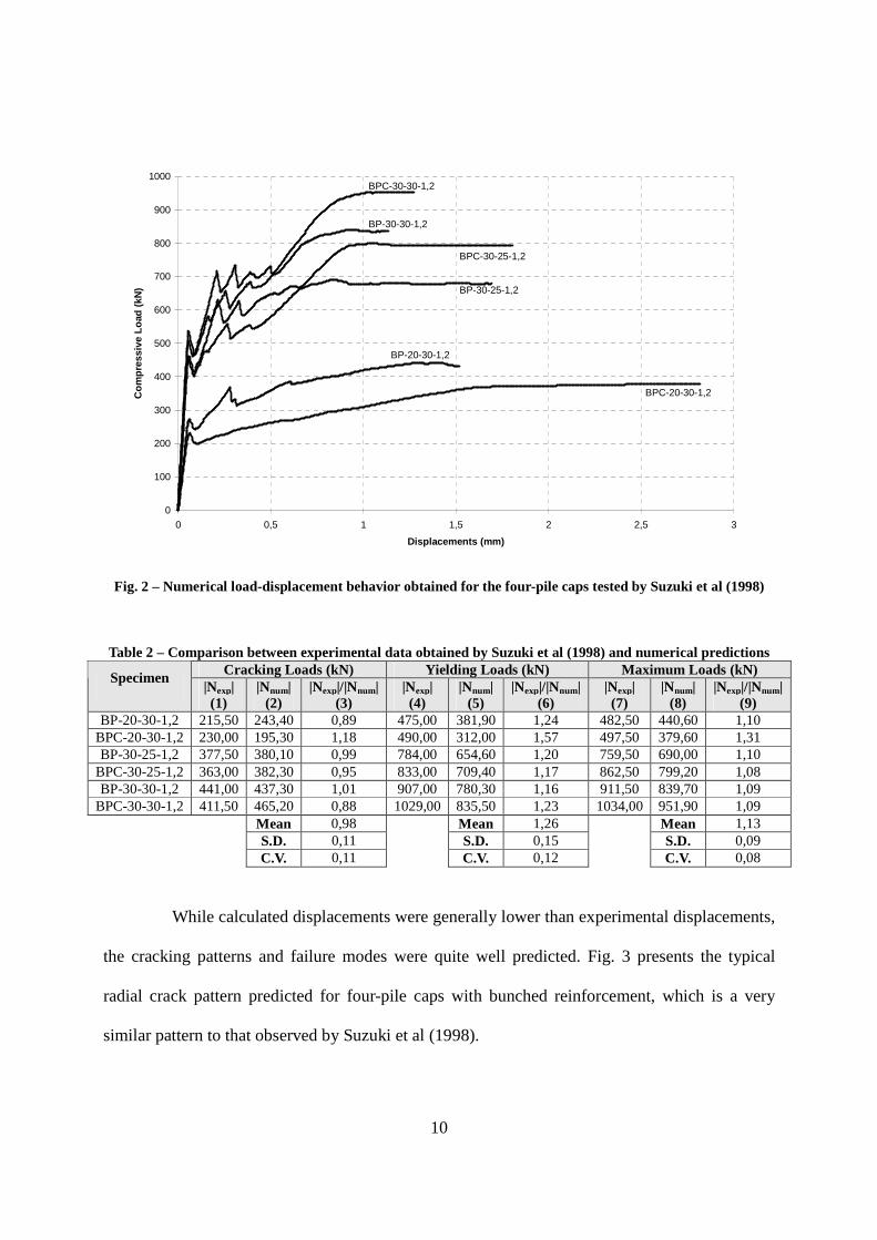
Fig. 2 presents the predicted load-displacement behavior for the simulated four-pile
caps using NLFEA. Table 2 presents in details some comparisons between the experimental
results obtained by Suzuki et al (1998) and the numeric predictions from the NLFEAs. The non-
linear predictions were reasonably close to the measured experimental results, leading to
coefficients of variations that were less than 15%.
10
0
100
200
300
400
500
600
700
800
900
1000
0 0,5 1 1,5 2 2,5 3
Displacements (mm)
Co
mp
ress
ive
Lo
ad (
kN)
BPC-30-30-1,2
BP-30-30-1,2
BPC-30-25-1,2
BP-30-25-1,2
BP-20-30-1,2
BPC-20-30-1,2
Fig. 2 – Numerical load-displacement behavior obtained for the four-pile caps tested by Suzuki et al (1998)
Table 2 – Comparison between experimental data obtained by Suzuki et al (1998) and numerical predictions Cracking Loads (kN) Yielding Loads (kN) Maximum Loads (kN) Specimen
|Nexp| (1)
|Nnum| (2)
|Nexp|/|Nnum| (3)
|Nexp| (4)
|Nnum| (5)
|Nexp|/|Nnum| (6)
|Nexp| (7)
|Nnum| (8)
|Nexp|/|Nnum| (9)
BP-20-30-1,2 215,50 243,40 0,89 475,00 381,90 1,24 482,50 440,60 1,10 BPC-20-30-1,2 230,00 195,30 1,18 490,00 312,00 1,57 497,50 379,60 1,31 BP-30-25-1,2 377,50 380,10 0,99 784,00 654,60 1,20 759,50 690,00 1,10
BPC-30-25-1,2 363,00 382,30 0,95 833,00 709,40 1,17 862,50 799,20 1,08 BP-30-30-1,2 441,00 437,30 1,01 907,00 780,30 1,16 911,50 839,70 1,09
BPC-30-30-1,2 411,50 465,20 0,88 1029,00 835,50 1,23 1034,00 951,90 1,09 Mean 0,98 Mean 1,26 Mean 1,13 S.D. 0,11 S.D. 0,15 S.D. 0,09 C.V. 0,11 C.V. 0,12 C.V. 0,08
While calculated displacements were generally lower than experimental displacements,
the cracking patterns and failure modes were quite well predicted. Fig. 3 presents the typical
radial crack pattern predicted for four-pile caps with bunched reinforcement, which is a very
similar pattern to that observed by Suzuki et al (1998).

11
Fig.3 – Predicted crack pattern at failure for pile cap BPC-30-30-1,2 (only crack widths over 0,2 mm)
4. VALIDATION OF THE PROPOSED STRUT-AND-TIE MODEL U SING NLFEA
Based on the accurate quantitative as well as qualitative performance obtained in the
previous simulations, the necessary confidence in this NLFEA program was obtained for reliably
predicting the behavior of four-pile caps designed with the proposed methodology. For these
additional investigations, four-pile caps subjected to the same loading conditions and different
heights (0.38≤ c/d ≤ 0.70), as shown in Fig. 4, were designed using the proposed model and
further analyzed using the nonlinear potentialities of DIANA software (Cervenka et al (2000)).
In order to evaluate the performance of the proposed model, the amount of
reinforcement were obtained by setting load factors and material reduction factors to 1.0. The
same methodology of not applying safety factor was used when defining material properties in
the selected commercial finite element software, i.e., characteristics strength for steel and
concrete were defined.
12
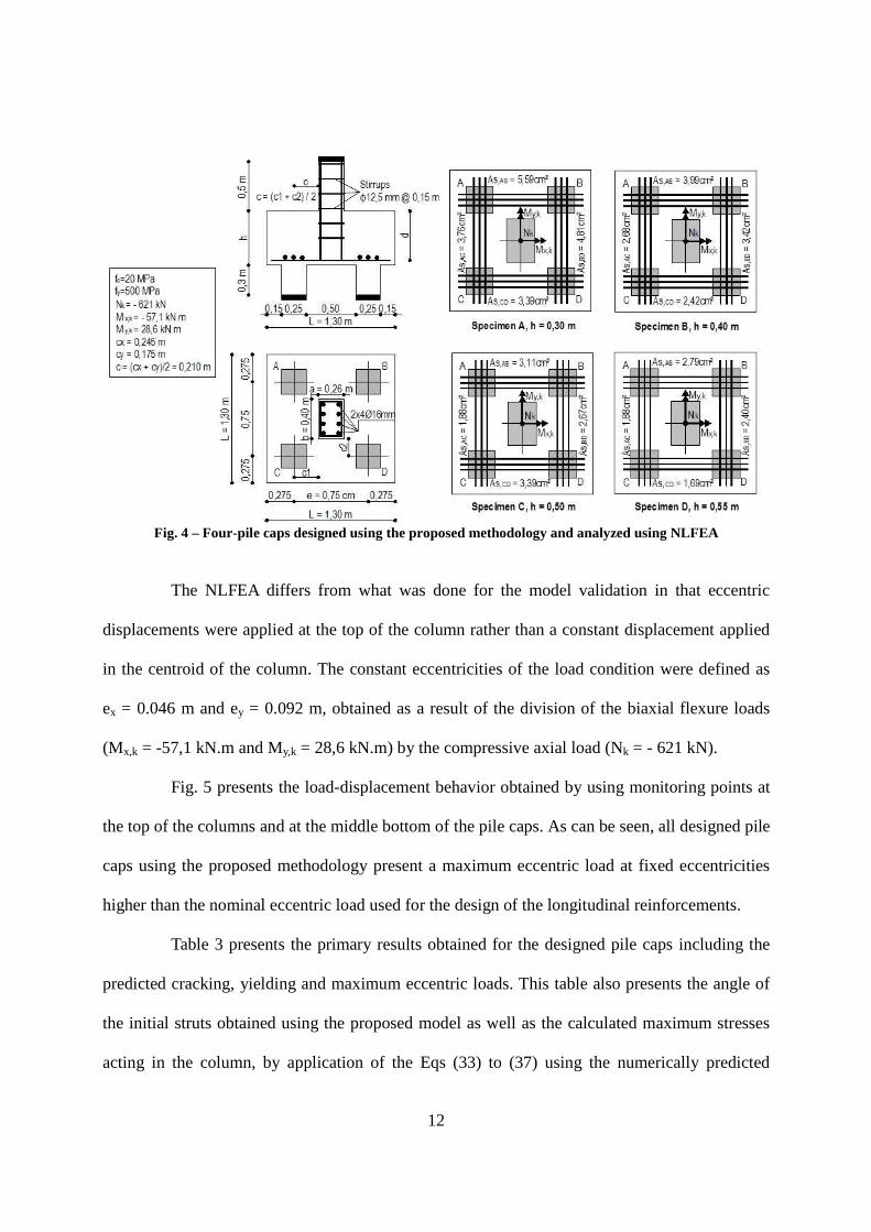
Fig. 4 – Four-pile caps designed using the proposed methodology and analyzed using NLFEA
The NLFEA differs from what was done for the model validation in that eccentric
displacements were applied at the top of the column rather than a constant displacement applied
in the centroid of the column. The constant eccentricities of the load condition were defined as
ex = 0.046 m and ey = 0.092 m, obtained as a result of the division of the biaxial flexure loads
(Mx,k = -57,1 kN.m and My,k = 28,6 kN.m) by the compressive axial load (Nk = - 621 kN).
Fig. 5 presents the load-displacement behavior obtained by using monitoring points at
the top of the columns and at the middle bottom of the pile caps. As can be seen, all designed pile
caps using the proposed methodology present a maximum eccentric load at fixed eccentricities
higher than the nominal eccentric load used for the design of the longitudinal reinforcements.
Table 3 presents the primary results obtained for the designed pile caps including the
predicted cracking, yielding and maximum eccentric loads. This table also presents the angle of
the initial struts obtained using the proposed model as well as the calculated maximum stresses
acting in the column, by application of the Eqs (33) to (37) using the numerically predicted

13
capacity.
0
200
400
600
800
1000
1200
0 0,25 0,5 0,75 1 1,25 1,5 1,75
Displacement (mm)
Ecc
entr
ic L
oad
(kN
)
Nk = 621 kNSpecimen A
Specimen B
Specimen D
Specimen C
Fig. 5 – Load-displacement behavior for the four-pile caps designed using the proposed methodology
Table 3 – Numerical results of the four-pile caps designed using the proposed model
Specimen c/d h
(m) d
(cm) Struts Angles
Ncrack
(kN) Nyield
(kN) Nmax (kN)
σσσσc,c (MPa)
σσσσc,y (MPa)
σσσσc,u (MPa)
Failure Mode
A 0,70 0,30 0,25
θA = 26,23o θB = 29,95o θC = 21,68o θD = 23,64o
287,40 - 669,50 0,48fc - 1,11fc Shear
B 0,53 0,40 0,35
θA = 34,60o θB = 38,89o θC = 29,10o θD = 31,50o
514,40 785,30 894,10 0,85fc 1,30fc 1,48fc Flexure
C 0,42 0,50 0,45
θA = 41,57o θB = 46,04o θC = 35,59o θD = 38,23o
702,60 795,00 943,20 1,16fc 1,32fc 1,56fc Flexure
D 0,38 0,55 0,50
θA = 44,58o θB = 49,04o θC = 38,49o θD = 41,20o
896,10 - 1044,00 1,48fc - 1,73fc Shear
14
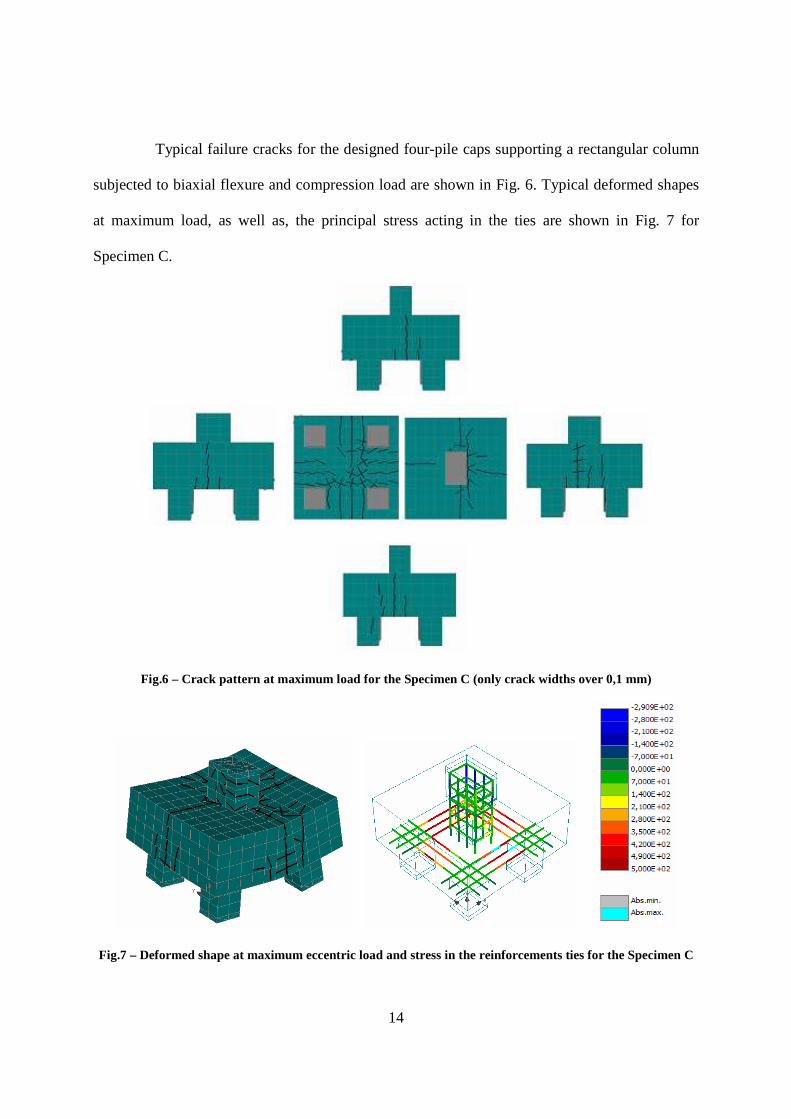
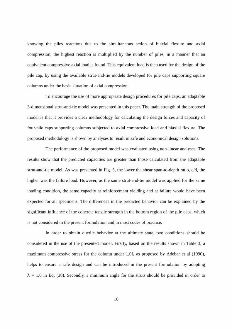
Typical failure cracks for the designed four-pile caps supporting a rectangular column
subjected to biaxial flexure and compression load are shown in Fig. 6. Typical deformed shapes
at maximum load, as well as, the principal stress acting in the ties are shown in Fig. 7 for
Specimen C.
Fig.6 – Crack pattern at maximum load for the Specimen C (only crack widths over 0,1 mm)
Fig.7 – Deformed shape at maximum eccentric load and stress in the reinforcements ties for the Specimen C

15
In order to assess the concrete contribution on the capacity of the pile caps, additional
analyses were conducted of unreinforced pile caps. Fig. 8 present the eccentric load-
displacement behavior of non-reinforced pile caps of different heights. As can be seen, for pile
caps with heights over 50 cm, no longitudinal reinforcement would be necessary to support the
design loads. These results show that concrete tensile strength, often neglected in structural
codes, is a critically important factor in the design of stocky member such as pile caps. Taking
into account that safety factors are additionally applied to the design, it is very clear that a large
portion of some pile caps will be reinforced.
0
100
200
300
400
500
600
700
800
900
1000
0 0,25 0,5 0,75 1
Displacement (mm)
Ecc
entr
ic L
oad
(kN
) Nk=621 kN
h = 0,30 m
h = 0,55 m
h = 0,40 m
h = 0,50 m
Fig.8 – Load-displacement behavior for the four-pile caps without adopting longitudinal reinforcement
5. CONCLUDING REMARKS
Due to the lack of a generic strut-and-tie model for the design of pile caps to support
realistically complex loadings from columns, designers commonly use engineering beam theory
or very simplified strut-and-tie models for the design of pile caps. In the latter approach,
16
knowing the piles reactions due to the simultaneous action of biaxial flexure and axial
compression, the highest reaction is multiplied by the number of piles, in a manner that an
equivalent compressive axial load is found. This equivalent load is then used for the design of the
pile cap, by using the available strut-and-tie models developed for pile caps supporting square
columns under the basic situation of axial compression.
To encourage the use of more appropriate design procedures for pile caps, an adaptable
3-dimensional strut-and-tie model was presented in this paper. The main strength of the proposed
model is that it provides a clear methodology for calculating the design forces and capacity of
four-pile caps supporting columns subjected to axial compressive load and biaxial flexure. The
proposed methodology is shown by analyses to result in safe and economical design solutions.
The performance of the proposed model was evaluated using non-linear analyses. The
results show that the predicted capacities are greater than those calculated from the adaptable
strut-and-tie model. As was presented in Fig. 5, the lower the shear span-to-depth ratio, c/d, the
higher was the failure load. However, as the same strut-and-tie model was applied for the same
loading condition, the same capacity at reinforcement yielding and at failure would have been
expected for all specimens. The differences in the predicted behavior can be explained by the
significant influence of the concrete tensile strength in the bottom region of the pile caps, which
is not considered in the present formulation and in most codes of practice.
In order to obtain ductile behavior at the ultimate state, two conditions should be
considered in the use of the presented model. Firstly, based on the results shown in Table 3, a
maximum compressive stress for the column under 1,0fc as proposed by Adebar et al (1990),
helps to ensure a safe design and can be introduced in the present formulation by adopting
λ = 1,0 in Eq. (38). Secondly, a minimum angle for the struts should be provided in order to
17
increase the final shear strength of the pile caps. Numerical results showed that yielding were
only possible when the inclination of the struts were between 29o and 46o. If the design intention
is to yield the reinforcement (flexure failure) before longitudinal splitting of the concrete struts
(shear failure), then the two previous recommendations should be followed.
The proposed adaptable strut-and-tie model is considered to provide a more rational
basis for the design and analysis of four-pile caps. Even so, it should be noted that the proposed
model may lead to the use of more than necessary amounts of longitudinal tension reinforcement.
The numerical simulations illustrated the capacity provided by the concrete alone would support
most service loads. This implies that field experience should not provide a good indication of the
appropriateness of design practice.
6. REFERENCES
1. ACI Committee 318, “Building Code Requirements for Reinforced Concrete (ACI 318-02)
and Commentary (ACI 318R-05)”. American Concrete Institute, Farmington Hills, MI, 2002.
2. ADEBAR, P.; KUCHMA, D.; COLLINS, M. P.. “Strut-and-Tie Models for the Design of Pile
Caps: An Experimental Study”. ACI Structural Journal, v.87, n.1, pp.81-92, 1990.
3. ADEBAR, P.; ZHOU, Z.. “Design of Deep Pile Caps by Strut-and-Tie Models”. In: ACI
Structural Journal, v. 93, no. 4, July-August , pp. 1-12, 1996.
4. AMERICAN ASSOCIATION OF STATE HIGHWAY AND TRANSPORTATION
OFFICIALS (AASHTO). “AASHTO LRFD Bridge Design Specifications”, 1st ed. Washington,
D. C., 1994.
5 BLÉVOT, J. L.; FRÉMY, R.. "Semelles sur Pieux". Institute Technique du Bâtiment et des
Travaux Publics, v.20, n.230, pp.223-295, Paris, 1967.

18
6. BLOODWORTH, A. G., JACKSON, P. A., LEE, M. M. K.. “Strength of Reinforced Concrete
Pile Caps”. Proceedings of the Institution of Civil Engineers, Structures & Buildings 156,
November, Issue SB4, pp.347–358, 2003.
7 CANADIAN STANDARDS ASSOCIATION (CSA). “CSA A23.3-M84. Code for the Design
of Concrete Structures for Buildings”. RexdaIe, Ont., 281 pp, 1984.
8. CAVERS, W.; FENTON, G. A.. “An Evaluation of Pile Cap Design Methods in Accordance
with the Canadian Design Standard”. Canadian Journal of Civil Engineering, v 31, n 1, February,
pp.109-119, 2004.
9. CERVENKA, V; JENDELE, L.; CERVENKA, J.. “ATENA Program Documentation – Part 1:
Theory”, Praha, Czech Republic, 2005.
10. COMISIÓN PERMANENTE DEL HORMIGÓN. “EHE - Instrucción de hormigón
structural”. Madrid, Spain, 1999. (In Spanish)
11. CLARKE, J. L.. “Behavior and Design of Pile Caps with Four Piles”. Technical Report,
n.42.489, Cement and Concrete Association, Wexham Springs, 1973.
12. REINECK, K., H, ed. “Examples for the Design of Structural Concrete with Strut and Tie
Models”, Chapter 9, pp.213-224. ACI SP-208. Farmington Hills, MI: ACI International, 2002.
13. IYER. P, K.; SAM, C.. “Three-Dimensional Analysis of Pile Caps”. Computers & Structures,
v.42, n.03, pp.395-411, 1992.
14. SCHLAICH, J.; SCHAFER, K.; JENNEWEIN, M.. "Toward a Consistent Design of
Reinforced Concrete Structures". Journal of Prestressed Concrete Structures, v.32, n.03, pp.74-
150, 1987.
15. SUZUKI, K.; OTSUKI, K.. “Experimental Study on Corner Shear Failure of Pile Caps”.
Transactions of the Japan Concrete Institute, v.23, 2002.

19
16. SUZUKI, K.; OTSUKI, K.; TSUBATA, T.. “Experimental Study on Four-Pile Caps with
Taper”. Transactions of the Japan Concrete Institute, v.21, pp.327-334, 1999
17. SUZUKI, K.; OTSUKI, K.; TSUBATA, T.. “Influence of Bar Arrangement on Ultimate
Strength of Four-Pile Caps”. Transactions of the Japan Concrete Institute, v.20, pp.195-202, 1998.
18. SUZUKI, K.; OTSUKI, K.; TSUCHIYA, T.. “Influence of Edge Distance on Failure
Mechanism of Pile Caps”. Transactions of the Japan Concrete Institute, v.22, pp.361-367, 2000.
ACKNOWLEDGMENTS
The present work was completed in the Newmark Laboratory, Department of Civil and
Environmental Engineering, University of Illinois at Urbana-Champaign. Financial support was
provided from the Brazilian government agency CAPES (Coordenação de Aperfeiçoamento de
Pessoal de Nível Superior) and is gratefully acknowledged.
COMPLETE CITATION FOR THIS PUBLICATION
R.A. Souza, D.A. Kuchma, J. Park, T.N. Bittencourt, "Non-Linear Finite Element Analysis of
Four-Pile Caps Supporting Columns Subjected to Generic Loading". Computers and Concrete,
Vol.4, No.5, pp.363-376, 2007. ISSN: 1598-8198
NOTATION
Nk = Nominal axial loading acting on the column;
Mx,k; My,k = Nominal flexure loading acting from the column on the pile cap about the x and y-axes;
ex,k; ey,k = Nominal eccentricities of the load from the x and y-axes;
a, b = Column dimensions;

20
RA,k; RB,k; RC,k; RD,k = Nominal pile reactions for piles A, B, C and D, respectively;
θA = Angle between projection LA and Strut A;
θB = Angle between projection LB and Strut B;
θC = Angle between projection LC and Strut C;
θD = Angle between projection LD and Strut D;
βA = Angle between projection LA and Tie AC;
βB = Angle between projection LB and Tie BD;
βC = Angle between projection LC and Tie CD;
βD = Angle between projection LD and Tie CD;
LA, LB, LC, LD = Horizontal projections of the struts A, B, C and D, respectively;
e = Pitch between center of piles;
c = Average distance between face column and pile centers;
c1, c2 = Distance between face columns and pile center in x and y-directions, respectively;
c/d = Shear span-to-depth ratio;
L = Pile cap length and width;
h = Pile cap height;
d = Effective height;
p = pile diameter or width;
CA,k; CB,k; CC,k; CD,k = Nominal forces acting in the struts A, B, C and D, respectively;
TAC,k; TBD,k; TCD,k; TAB,k = Nominal forces acting in the ties AC, BD, CD and AB, respectively;
γ, φ = Safety factor for loads and strength reduction factor for materials, respectively;
AsAC, As,BD, As,CD, As,AB = Demanded reinforcement for ties AC, BD, CD and AB, respectively;
σ1,c; σ2,c; σ3,c; σ4,c; = Stresses acting at the corners of the column;
σmax = Maximum compressive stress acting at the corners of the column;
σc,c; σc,y; σc,u = Maximum compressive stress at the corners of column for the crack, yield and ultimate
(maximum) loads;
fc = Concrete compression strength;

21
fy = Steel yielding strength.
keywords: pile caps, strut-and-tie models, flexure strength, shear strength, concrete design
TABLES AND FIGURES
List of Tables:
Table 1 – Properties and average results of the four-pile caps tested by Suzuki et al (1998)
Table 2 – Comparison between experimental data obtained by Suzuki et al (1998) and numerical predictions
Table 3 – Numerical results of the four-pile caps designed using the proposed model
List of Figures:
Fig. 1 – Proposed strut-and-tie model for four-pile caps and positive signal convention for biaxial flexure
Fig. 2 – Numerical load-displacement behavior obtained for the four-pile caps tested by Suzuki et al (1998)
Fig.3 – Predicted crack pattern at failure for pile cap BPC-30-30-1,2 (only crack widths over 0,2 mm)
Fig. 4 – Four-pile caps designed using the proposed methodology and analyzed using NLFEA
Fig. 5 – Load-displacement behavior for the four-pile caps designed using the proposed methodology
Fig.6 – Crack pattern at maximum load for the Specimen C (only crack widths over 0,1 mm)
Fig.7 – Deformed shape at maximum eccentric load and stress in the reinforcements ties for the Specimen C
Fig.8 – Load-displacement behavior for the four-pile caps without adopting longitudinal reinforcement