Embed Size (px)
Citation preview

Nonlinear Adaptive Sliding-Mode Control Design for Two-Wheeled Human Transportation Vehicle
Abstract—This paper presents adaptive sliding-mode control methods for self-balancing and yaw rate control of a dynamically two-wheeled human transportation vehicle (HTV) with mass variations and system uncertainties. The proposed controllers aim to provide consistent driving performance for system uncertainties and different drivers whose weights cause parameter variations of the HTV. By decomposing the overall system into the yaw subsystems and the self-balancing subsystems with parameters variations with respect to different riders, two adaptive sliding mode controls are proposed to achieve self-balancing and yaw control. Numerical simulations and experimental results on different terrains show that the proposed adaptive sliding mode controllers are capable of achieving satisfactory control actions to steer the vehicle.
Keywords adaptive control, gyroscope, inverted pendulum, robotics transporter, sliding mode control.
I. INTRODUCTION Recently, self-balancing two-wheeled transporters, like the
SegwayTM, have been well recognized as powerful personal transportation vehicles. The kind of transporter can be usually constructed by a synthesis of mechatronics, control techniques and software. For example, the SegwayTM is made by quite high-tech and high-quality dedicated components. In contrast to the SegwayTM, many researchers [1]-[2] presented low-tech self-balancing transporters and claimed that the vehicle can be built using the off-the-shelf inexpensive components. With the advent of modern technology, such transporters with sophisticated safety features can be cost down so that they, like traditional bicycles, have high potential to become prevalent two-wheeled HTVs, satisfying human transportation requirements.
Design and implementation of a safe and practical self-balancing HTV is a very interesting problem. Grasser et al. [1] built a scaled down prototype of a digital-signal-processor (DSP) controlled two wheeled vehicle based on the inverted pendulum with weights attached to it, and Pathak et al. [3] studied the dynamic equations of the wheeled inverted pendulum by partial feedback linearization. However, they are test prototypes, aiming at providing several theoretical design and analytical approaches. Furthermore, several researchers in [4]-[8] proposed useful control and implementation techniques for four-wheeled vehicles, two-wheeled vehicles with differential driving, and electric scooter. However, these methods can not be directly applied to address both self balancing and yaw control problems for the two-wheeled self-balancing HTV.
Recently, sliding mode control (SMC) have been adopted widely for nonlinear system modeling and control because they possess simple structure, good local approximating performance, particular resolvability, and function equivalence to a simplified class of nonlinear systems. Many successful applications on fuzzy control were reported in various areas; for example, Nawawi et al [10] proposed the modeling of 2-wheels Inverted Pendulum and the design of proportional integral sliding-mode control (PISMC) for the system., Yu etal [11] presented a variable structure control (VSC) algorithm to achieve the prespecified trajectory tracking on mechatronic arms. Lam et al [12] proposed two adaptive fuzzy controllers are used to control the invented pendulum to track a given position and balance the pole.
The paper contributes to the design of two adaptive sliding-mode controllers for achieving self-balancing and yaw control. Like the JOE in [1], the proposed controllers are synthesized by decoupling this vehicle system into two subsystems: yaw motion and mobile inverted pendulum. In comparison with the state-feedback design presented by Grasser et al. [1], the key features of the proposed control method hinge on its nonlinear mathematical modeling with coulomb and static frictions, and its adaptive control for the HTV with unknown plant parameters, unknown frictions and linearized errors. Moreover, the proposed controllers are useful in keeping consistent driving performance for different riders.
The rest of the paper is outlined as follows. Section II briefly describes the system design of the vehicle and Section III shows the synthesis procedures of the two adaptive controllers using sliding-mode control. In Section IV computer simulations and experimental results are presented and discussed. Section V concludes the paper.
II. SYSTEM DESCRIPTION AND MODELING A. Control Architecture
Fig.1 depicts the free body diagram of the HTV, and Fig.2 illustrates the block diagram of the HTV control system. The DSP controller with built-in A/D conversion is responsible for executing both adaptive yaw motion and self-balancing control algorithms. The pitch rate Pω from the gyroscope and the pitch angle Pθ from the tilt sensor are utilized via the controllers to maintain the human body on the footplate without falling. Note that both feedback signals are processed
Shui-Chun Lin, Member, IEEE, Department of Electronic
Engineering, National Chin-Yi University of Technology,
Taichung 41101, Taiwan, R. O. C.email:[email protected]
Ching-Chih Tsai*, Senior Member, IEEE,Department of Electrical Engineering,
National Chung-Hsing University, Taichung 40027, Taiwan, R. O. C.
email:[email protected].
Hsu-Chih Huang, Member, IEEE,Department of Computer Science and
Information Engineering, HungKuang University,
Taichung, Taiwan, R. O. C.email:[email protected]
Proceedings of the 2009 IEEE International Conference on Systems, Man, and CyberneticsSan Antonio, TX, USA - October 2009
978-1-4244-2794-9/09/$25.00 ©2009 IEEE2034

px
pyabsy
pM g
L
pθ
yθ
RMx
absxRLx
TLHLH
RLbxTLV
/ 2D
LC
RC
RRy
LV
RV
TRV RRbx
RH
RRxabsz
z
TRH
Fig.1. Free body diagram of the HTVs.
Rω RMxRMvpθpω
yθyω
0pcθ =0pcω =
0ycθ =
yC
Cθ
LCRC
Adaptive sliding mode self-balancing control
Tilt Sensor
Gyroscope
Potentiometer
0.5
0.5−
Two Wheeled Vehicle
Right Motor
Left MotorLω
PWMbased driver0.5
0.5−
Torque speed conver-tion
Adaptive sliding mode yaw control
DSP Controller
Fig. 2. Block diagram of the HTV controller.
by two first-order filters, thus removing unwanted noise. The potentiometer is adopted to measure the yaw angle from the handlebar, and the yaw signal is then taken by the DSP controller for further yaw control. The output torque commands from the DSP controller are converted into the corresponding speed commands via a torque-to-speed formula.
B. Mathematical Modeling To obtain high-performance steering experience for
different riders, it is necessary to develop a mathematical model of the vehicle. The nonlinear mathematical model of the HTV with both frictions is modified from [1] and given in the following state equation
2 2 2
4 4 4
6 6 6
22 23
43
66
0 0 0sin
0 0 0sin
0 0 0
RMRM
RM PRM
p LP
P Rp
yy
yy
vA v A B B fv
CA CB B f
A B B f
xθ
ωθθω
ωθωω
+
== + +
−
(1)
where RMx [m] and RMv [m/s] respectively denote the position and velocity of the HTV respect to the world frame; pθ [rad] and pω [rad/s] respectively represent the pitch angle and pitch angle rate of the HTV; yθ [rad] and yω [rad/s] respectively stand for the yaw angle and yaw rate of the HTV; LC [N-m] and RC [N-m] respectively denote the applied torques on the left and right wheels; ( 2,4,6)if i = respectively denotes the
uncertain term which may include coulomb and static frictions, and linearized errors. Similar to the vehicle, called JOE, developed by Grasser et al.[1], the following decoupling transformation from Cθ and yC into the wheel torques RCand LC is used to decouple the system model such that both yaw motion and inverted pendulum controllers are independently designed.
0.5( ), 0.5( )L y R yC C C C C Cθ θ= + = − (2) which converts the system (1) into two subsystems; one is the mobile inverted pendulum subsystem described by
4 4 4 443 4
0( ), /
sinPP
PP
C f f f BA B θ
ωθθω
= + + = (3)
and the other is the yaw control subsystem described by
6 6 6 666 6
0 1 0, /
0yy
yyy
C f f f BA B
θθωω
= + + = (4)
Note that the model for the uncertainties, 2f , 4f and 6f can be realistically modeled by
6
2 23 24 25
4 45
63 64
dRL dRR dP
dP
dRL dRR
f B f B f B ff B ff B f B f
= + +== +
where dRLf , dRRf and dPf are three disturbance forces exerted on the left wheel, the right wheel, and the handle-bar, respectively.
2
23 24 ,2 R
RB BJ α
= =2
251 ,
2 cos P
P
R P
JRBJ M L
θ
αβ θ= ⋅ 45
1 ,p
BMβ
=
63 64 / 2 ,pyB B D pJ= − = where 2 / 1,R RM R Jα = +
[ ]/ cos cosP PP PJ M L Lθβ θ θ= + and R is radius of the wheels,
RJ is moment of inertia of the wheel, PJ θ is moment of inertia of the chassis with respect to the z axis, pM is mass of the chassis with the weight of the rider, L is distance between the z axis and the center of gravity of the chassis,
pθ is pitch angle, D is lateral distance between the contact patches of the wheels, pyJ is moment of inertia of the chassis
with respect to the y axis, 2 2 21 [ ( )/2 ],R R pyp D J M R J R= + +and RM is mass of the wheel.
III. CONTROLLER DESIGN A. Nonlinear Sliding-mode Self-Balancing Control Design
This subsection will consider constructing an adaptive sliding-mode self-balancing controller for the subsystem (3) where 43A and 4B are known, but the nonlinear term 4f is unknown. A block diagram of the control system for the transporter is shown in Fig.2. The control objective is to control the angle position Pθ to reach to the command position pcθ without error under the aforementioned settings. Due to the nonlinearity of system mode (3), the well-known sliding mode technique is adopted to accomplish the control
2035

goal. To maintain the angle position Pθ at 0Pcθ = , one recalls the nonlinear subsystem model of the human transporter:
43 4 4sinP P
P PA f B Cθ
θ ωω θ
== + +
(5)
To achieve self-balancing of the transporter, one defines the sliding surface by
1 1, 0p ps K Kθ ω= + > (6) Let 1 43 4 4( sin ) /P PG K A f Bω θ= + + and the uncertainty satisfies the following inequality
( , )P PG δ θ ω≤ (7) To stabilize the system (5), we propose the following torque control:
( , ) sgn( )P PC sθ β θ ω= , ( , )P Pβ θ ω > ( , )P Pδ θ ω (8) To show that Pθ will tend to zero as time approaches infinity, the following Lyapunov function is chosen by
21 / 2V s= (9)
Then the time derivative of the Lyapunov function 3Vbecomes
1 43 4 4 1sin ( )P pV ss s A B C f Kθθ ω= = + + +
4[ ]sB C Gθ= + (10) Substituting (8) into (10) leads to
[ ]1 4 ( , ) sgn( ) ( , )P P P PV sB sβ θ ω δ θ ω= +Using the inequality (7) and the subsequent inequality
[ ] ( )( , ) sgn( ) ( , ) ( , ) ( , ) 0P P P P P P P Ps s sβ θ ω δ θ ω β θ ω δ θ ω+ ≥ − ≥
One obtains ( )1 4 ( , ) ( , ) 0P P P PV B sβ θ ω δ θ ω= − ≤ (11)
Since 1V is semi negative-definite, the Lyapunov stability theory implies 0s → as t → ∞ . On the sliding surface 1 10 p p p ps K Kθ ω θ θ= = + = + , it is easy to show that
0Pθ → as t → ∞ .
Theorem 1 Consider the subsystem (5) with the proposed control (8). Then the pitch will remain at 0Pcθ = as t → ∞ .
B. Nonlinear Adaptive Sliding-mode Self-Balancing Control Design Due to difficulty to estimate ( )xδ in practice, it is rather
difficult to implement the proposed self-balancing control law (8). To circumvent the shortcoming, this subsection will pay effort to design a new kind of adaptive robust self-balancing control law so that the transporter can be maintained in the desired operating range of the pitch angle. In doing so, suppose that ( )xδ is bounded, i.e.,
max( , )P PG δ θ ω δ≤ ≤ (12) To stabilize the system (5), the following torque control is proposed by
0ˆ( ) sgn( )C sθ β δ= + , 0β >0 (13)
where δ̂ is to be estimated such that pθ will tend to zero as time approaches infinity. This can be easily proven by choosing the following Lyapunov function
2 22 4(min)
ˆ( / 2) ( / 2 )V s Bδ λ= + (14) where 4(min) / 0B λ > and 4(min) 4 0B B≤ < over the desired operating range of the pitch angle. Therefore, the time derivative of the Lyapunov function 2V is found by
4min 4min2 1( )p p
B BV ss s Kδδ θ ω δδλ λ
= + = + +
[ ]{ }4minˆ( )/B s C Gθ δ δ λ= + + − (15)
where maxˆ.δ δ δ= − If the adaptive parameter law is selected
by ˆ , 0sδ λ λ= < (16)
then 4min 4min4 4min 4min 0
ˆ[ ]B BV ss B s B sδδ δ δ δ βλ λ
≤ + ≤ + − +
4min 0 0B sβ= ≤ (17) From (17), the Lyapunov stability theory and the comparison lemma implies 0s → as t → ∞ .
Theorem 2 Consider the subsystem (5) with the proposed adaptive robust control (13) and the parameter adjustment law (16).Then the angle position Pθ will be maintained at 0Pcθ = ,i.e., 0Pθ → as t → ∞ .
C. Nonlinear Sliding-mode Yaw Control Design This subsection will consider constructing an adaptive
sliding-mode self-balancing controller for the subsystem (4) where 66A and 6B are known, but the nonlinear term 6f is unknown. A block diagram of the control system for the transporter is shown in Fig.2. Since the potentiometer is employed to measure the angle difference between the equilibrium point and the yaw angle the rider intended to achieve, the adaptive yaw control problem is reduced to an adaptive regulation problem. Therefore, the backstepping technique is used to attain the sliding-mode yaw controller by choosing the virtual control y y yKω θ= − and the Lyapunov
function 23 / 2yV θ= , and then stabilizing the yθ - dynamics.
Next, define the second backstepping error ( ) ( )y y e y e y y ye ye y yey y K Kξ ω φ ω φ ω θ θ θ= − = − = + = + (18)
Differentiating yξ gives
66 6 6
666 6
6
( )
( )
y y y y y y y y
yy y
K A B C f K
K AB C f
B
ξ ω θ ω ω
ω
= + = + + +
+= + +
(19)
In order to stabilize the yaw control subsystem, we will consider the sliding surface
y y yes Kη ω θ= = + (20) Differentiating s gives
2036

( ){ }6 66 6 6/ ( )y y ys B K A B C fη ω= = + + + (21)
where 6666 1 6 0
6
0, , yy
K AK A K f K
B+
+ > < <
To stabilize the system (4), we propose the following torque control:
( )1 0 sgn( )y yC K K sω= − − (22) The following Lyapunov function candidate is chose by
23 / 2V s=
Differentiating the Lyapunov function 3V yields
( )663 6 6 1 0
6
yy y
K AV ss B s sf K K s
Bω ω
+= = + − +
( )
( )
666 6 1 0
6
666 1 0 6
6
0
yy y
yy
K AB s s f K K s
B
K AB K K f s
B
ω ω
ω
+≤ + − +
+= − − − − <
(23)
Since 3V is semi negative-definite, the use of the comparison lemma implies 0s → as t → ∞ . On the sliding surface 0 y y ys Kω θ= = + , it is easy to show that 0yθ →as t → ∞ .
Theorem 3 Consider the subsystem (4) with the proposed control (22). Then the pitch will remain at 0Pcθ = as t → ∞
D. Nonlinear Adaptive Sliding-mode Yaw Control Design This subsection is devoted to constructing an adaptive
sliding-mode yaw controller for the subsystem (4) with the two parameters, 66A and 6B , and the unknown nonlinear term 6f . Since the potentiometer is employed to measure the angle difference between the equilibrium point and the yaw angle the rider intended to achieve, the adaptive yaw control problem is reduced to an adaptive regulation problem. Therefore, similar to the previous subsection, the backstepping technique is again used to attain the adaptive yaw controller by choosing the virtual control y y yKω θ= − and the Lyapunov
function 23 / 2V s= , and then stabilizing the yθ - dynamics.
Next, define the second backstepping error ( )y y y y y y y yy K Kξ ω φ ω θ θ θ= − = + = + (24)
Differentiating yξ gives
( )66 6 6
66 6 6
666 6
6
( )
( )
( )
y y y y y y y y
y y y
yy y
K A B C f K
K A B C f
K AB C f
B
ξ ω θ ω ω
ω
ω
= + = + + +
= + + +
+= + +
(25)
In order to stabilize the yaw control subsystem, the implicit
control yC with estimated parameters 1K̂ and 0K̂ is proposed as follows; for 2K > 0 and yK >0,
( )1 0 2 2ˆ ˆ sgn( ) , 0y yC K K s K Kω= − − − > (26)
The estimated parameters, 1K̂ and 0K̂ are defined
by 0 0 0ˆK K K= − and 1 1 1
ˆK K K= − differentiating the two
equations to get 0 0ˆK K= − and 1 1
ˆK K= − . The following Lyapunov function candidate is employed to find the parameter updating laws
2 2 26 64 0 1
0 1
12 2 2
B BV s K Kλ λ
= + + (27)
Where 0 10, 0.λ λ> > Differentiating the Lyapunov function 4V yields
24 66 66
6 66 6 6
6 6
ˆ( / )
ˆ ˆ ˆ [( ) / / ]
ˆ ˆ [ ( / )] ( / )
yp y y y y ay
yp y y y y y y y by
Ty y uy y y y y
V K K A A r
B K A K B B r
B U S U r B rε
θ ω ξ
ξ θ ω ξ ω ξ
ξ ε ξ ε
≤ − + −
+ − − − −
+ − + −
(28)
If the following parameter adaptation rules are chosen by
1 1
0 0
ˆ
ˆyK s
K s
λ ω
λ
=
= (29)
Then 4V becomes 4 6 2 0V B K s= − ≤ which implies 0yθ →as t → ∞ . The following summarizes the result. Theorem 4 Consider the subsystem (4) with the proposed adaptive sliding-mode yaw control (26) with the parameter updating laws (29). Then 0y ycθ θ→ = , as t → ∞ .
IV. SIMULATIONS, EXPERIMENTAL RESULTS AND DISCUSSION
A. Mechatronic Design Fig.3 displays the photographs of the laboratory-based
personal two-wheeled HTV with differential driving. This vehicle is composed of one footplate, two 24V DC motors with a gearbox of ratio 20:1, two stamped steel wheels with 16-inch tires, two 12-volt sealed rechargeable lead-acid batteries in series, two motor drivers, a single chip DSP-TMS320LF2407 from Texas Instruments as a main controller, one handle-bar with a potentiometer as a position sensor, one gyroscope and one tilt sensor. The two motor drivers use dual H-bridge circuitry to deliver PWM-based power to drive the two DC servomotors. Sending PWM signals to the drives, theDSP outputs control signals, ranging from 0 V and 3.3 VDC, to achieve self-balancing and yaw motion of the HTV. The gyroscope and the tilt sensor are employed for measuring the rate and the angle of the inclination of the footplate caused by the rider. The two rechargeable lead-acid batteries directly provide power for the two DC servomotors, drives, the controller and all the sensors via DC-DC buck conversion.
2037

(a) (b) Fig.3. Laboratory-built personal two-wheeled HTV: (a) Front
view (no human stand on it). (b) Bottom view.
Fig.4. Simulation result of the self-balancing tracking
Fig.5. Sliding mode control with self-balancing angle.
B. Adaptive Sliding-mode Self-Balancing Control This section is devoted to describing simulation results
of the proposed adaptive Sliding-mode self-balancing control method. The relevant parameters used for the simulation are: 0.025 radcomθ = , 655PK = , 1K = 50, 0.0001br = ,
0.001wr = , 0.0001ar = . The control signal is limited to the output interval between -512 and 512. Figs.4 and 5 show the angle response of the inverted pendulum subsystem, indicating that the angle approached the desired angle about at 0.9 seconds.
C. Adaptive Sliding-mode Yaw Control This subsection will conduct several simulations to
examine the effectiveness of the proposed nonlinear sliding-mode yaw control. The relevant parameters used for simulations are: 0.000001 radcomθ = , 1 10000K = , 0 0.01β = ,
0.001λ = − . Fig.6 presents the sliding surface of the controlled yaw angle subsystem. Fig.7 presents the simulation results of the yaw angles with initial errors of 0.2 rads± .Clearly, the yaw angle tends to zero after 0.4 seconds.
D. Experimental Results and Discussion The objective of the experiments is to examine the
performance of the proposed sliding mode control laws for
Fig.6. Sliding surface of the yaw angle subsystem.
Fig.7. Simulation results of the yaw angle tracking.
(a) (b)
Fig.7. The HTV ridden by students on a smooth floor. (a) Moving forward. (b) Moving backward.
Fig.8. The HTV moving on (a) Turning right. (b) Turning right.
2038
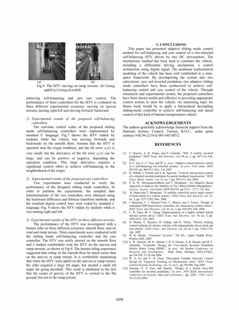
(a) (b) Fig.9. The HTV moving on ramp terrains. (b) Going
uphill.(c) Going downhill.
achieving self-balancing and yaw rate control. The performance of these controllers for the HTV is evaluated on three different experimental scenarios: moving on uneven terrains, turning right/left and moving forward/ backward.
1) Experimental results of the proposed self-balancing controllers
The real-time control codes of the proposed sliding mode self-balancing controllers were implemented by standard C language. Fig.7 shows the HTV ridden by students while the vehicle was moving forwards and backwards on the smooth floor. Assume that the HTV is operated near the origin condition, and the tilt error ( )e tθ is very small, but the derivative of the tilt error ( )e tθ can be large, and can be positive or negative, depending the operation condition. This large derivative requires a significant control effort to achieve self-balancing in the neighborhood of the origin.
2) Experimental results of the proposed yaw controllers Two experiments were conducted to verify the
performance of the designed sliding mode controllers. In order to perform the experiments, the sampled data transformations of the two controllers were obtained using the backward difference and bilinear transform methods, and the resultant digital control laws were coded by standard Clanguage. Fig. 8 shows the HTV ridden by students while it was turning right and left.
3) Experimental results of the HTV on three different terrains The performance of the HTV was investigated with a
human rider on three different scenarios: smooth floor, uneven road and ramp terrain. Three experiments were conducted with the sliding mode self-balancing controller and the yaw controller. The HTV was safely steered on the smooth floor and a student comfortably rode the HTV on the uneven and ramp terrains, as shown in Fig.9. The human riding experience suggested that riding on the smooth floor be much easier than on the uneven or ramp terrain. It is worthwhile mentioning that when the HTV went uphill on the uneven or ramp terrain, the rider required a large tilt angle, but needed a small tilt angle for going downhill. This result is attributed to the fact that the centre of gravity of the HTV is vertical to the flat ground, but not to the ramp terrain.
V. CONCLUSIONS This paper has presented adaptive sliding mode control
method for self-balancing and yaw control of a two-wheeled self-balancing HTV driven by two DC servomotors. The mechatronic method has been used to construct the vehicle, including a differential driving mechanism, a control architecture using digital signal. The nonlinear mathematical modeling of the vehicle has been well established in a state-space framework. By decomposing the system into two subsystems: yaw and inverted pendulum, two adaptive sliding mode controllers have been synthesized to achieve self-balancing control and yaw control of the vehicle. Through simulation and experimental results, the proposed controllers have been shown useful and effective in providing appropriate control actions to steer the vehicle. An interesting topic for future work would be to apply a hierarchical decoupling sliding-mode controller to achieve self-balancing and speed control of this kind of human transportation vehicle.
ACKNOWLEDGEMENTS The authors gratefully acknowledge financial support from the National Science Council, Taiwan, R.O.C., under grant contract NSC96-2218-E-005-045-MY2.
REFERENCES
[1] F. Grasser, A. D. Arrigo, and S. Colombi, “JOE: A mobile, inverted pendulum,” IEEE Trans. Ind. Electron., vol. 49, no. 1, pp. 107-114, Feb. 2002.
[2] S. C. Lin, C. C. Tsai, and W. L. Luo, “Adaptive neural network control of a self-balancing two-wheeled scooter,” In proc. 33rd Annu. IEEE IECON. pp. 868-873, Nov. 5-8, 2007.
[3] K. Pathak, J. Franch, and S. K. Agrawal, “Velocity and position control of a wheeled inverted pendulum by partial feedback linearization,” IEEE Trans. Robot. Autom., vol. 21, no. 3, pp. 505-513, Jun. 2005.
[4] P. K. W. Abeygunawardhana and T. Murakami, “An Adaptive Based Approach to Improve the Stability of Two Wheel Mobile Manipulator,”in proce. In proc. 33rd Annu. IEEE IECON. pp.2712 – 2717, 5-8, Nov.
[5] H. Ohara and T. Murakami, “A stability control by active angle control of front-wheel in a vehicle system,” IEEE Trans. Ind. Electron. vol. 55, no. 3, pp. 1277-1285, Mar. 2008.
[6] I. Baturone, F. J. Moreno-Velo, V. Blanco, and J. Ferruz, “Design of embedded DSP-based fuzzy controllers for autonomous mobile robots,” IEEE Trans. Ind. Electron., vol. 55, no. 2, pp. 928-936, Feb. 2008.
[7] C. H. Chen; M. Y. Cheng “Implementation of a highly reliable hybrid electric scooter drive,” IEEE Trans. Ind. Electron., vol. 54, no. 5, pp. 2462-2473, Oct. 2007.
[8] N. Mutoh, Y. Hayano,; H .Yahagi, and K. Takita, “Electric braking control methods for electric vehicles with independently driven front and rear wheels,” IEEE Trans. Ind. Electron. vol. 54, no. 2, pp. 1168-1176, Apr. 2007.
[9] H. K. Khalil, “Nonlinear Systems,” 3rd Ed., Upper Saddle River, Prentice Hall, 2002.
[10] S. W. Nawawi, M. N. Ahmad, J. H. S. Osman, A. R. Husain and M. F. Abdollah, “Controller Design for Two-wheels Inverted Pendulum Mobile Robot Using PISMC,” In proc. 4th Student Conference on Research and Development., Shah Alam, Selangor, MALAYSIA, pp.194-199, 27-28 Jun.2006.
[11] W. S. Yu and Y. H. Chen, “Decoupled Variable Structure Control Design for Trajectory Tracking on Mechatronic Arms” IEEE Trans. Control Systems Technology, vol. 13, no.5, pp.798-806, Sep.2005
[12] Xiaojun, X. Z. Gao, and Xianlin, “Design of a hybrid fuzzy-PD controller for inverted pendulum,” In proc. 2004 IEEE International Conference on Systems, Man and Cybernetics, pp. 2286 – 2291, vol.3, 10-13 Oct.2004.
2039


![Improved Sliding Mode Nonlinear Extended State …...nonlinear systems in the presence of mismatched disturbances and uncertainties. People in [23] presented an adaptive fuzzy observer](https://img.dokumen.tips/doc/110x75/5f5d5027bd05ee195d603c85/improved-sliding-mode-nonlinear-extended-state-nonlinear-systems-in-the-presence.jpg)