Embed Size (px)
Citation preview

NAM NGUM 3 HYDROPOWER PROJECT
M. MONKACHI / Q. BERCHER
CFBR 2019 – Marseille – 31 January 2019

■ Tributary of Mekong River
■ Watershed area : 16 640 km²
■ 3 operational HPPs (Nam Ngum 1, 2 & 5)
■ 2 projects under construction (Nam Ngum 3 & 4)
Project characteristicsNam Ngum River
Project characteristics
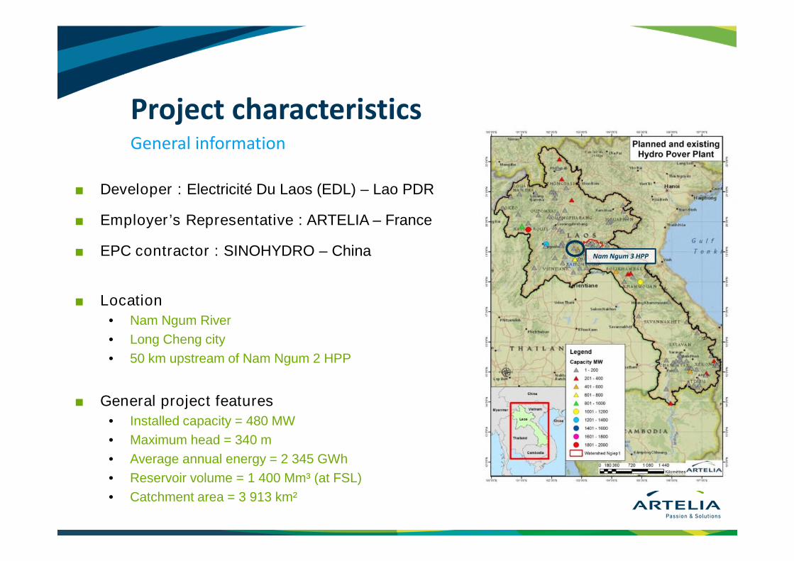
■ Developer : Electricité Du Laos (EDL) – Lao PDR
■ Employer’s Representative : ARTELIA – France
■ EPC contractor : SINOHYDRO – China
■ Location
• Nam Ngum River
• Long Cheng city
• 50 km upstream of Nam Ngum 2 HPP
■ General project features
• Installed capacity = 480 MW
• Maximum head = 340 m
• Average annual energy = 2 345 GWh
• Reservoir volume = 1 400 Mm³ (at FSL)
• Catchment area = 3 913 km²
General information
Nam Ngum 3 HPP
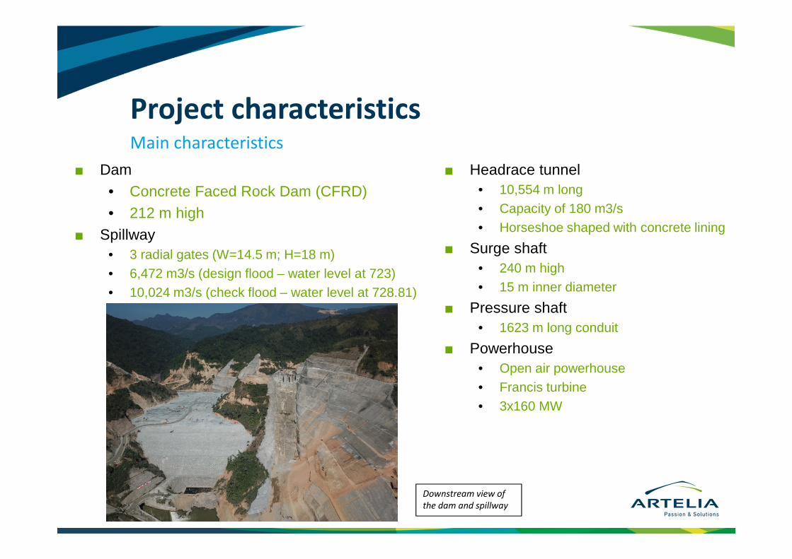
■ Dam
• Concrete Faced Rock Dam (CFRD)
• 212 m high
■ Spillway
• 3 radial gates (W=14.5 m; H=18 m)
• 6,472 m3/s (design flood – water level at 723)
• 10,024 m3/s (check flood – water level at 728.81)
Project characteristicsMain characteristics
■ Headrace tunnel
• 10,554 m long
• Capacity of 180 m3/s
• Horseshoe shaped with concrete lining
■ Surge shaft
• 240 m high
• 15 m inner diameter
■ Pressure shaft
• 1623 m long conduit
■ Powerhouse
• Open air powerhouse
• Francis turbine
• 3x160 MW
Downstream view of the dam and spillway
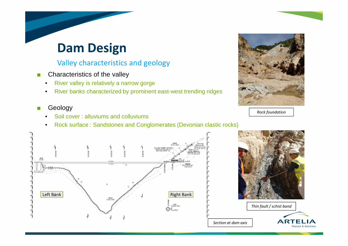
■ Characteristics of the valley
• River valley is relatively a narrow gorge
• River banks characterized by prominent east-west trending ridges
■ Geology
• Soil cover : alluviums and colluviums
• Rock surface : Sandstones and Conglomerates (Devonian clastic rocks)
Dam DesignValley characteristics and geology
Section at dam axis
Left Bank Right Bank
Rock foundation
Thin fault / schist band

Dam Design
Nam Ngum river valley at dam site

■ Maximum height above foundation = 212 m
■ Crest length = 518 m
■ Crest width = 8 m
■ Slopes
• Upstream : 1V : 1.4 H
• Downstream : 1V : 1.4 H between two berms (1 V : 1.5 H equivalent slope)
■ Dam backfill volume = about 15 Mm³
■ Concrete face slab surface = 130,000 m²
Dam DesignDam geometry
Dam section
Upstream Downstream

Dam DesignDam materials – Trial Panels
■ Gneiss Quarry
■ Trial Panel

Dam DesignDam materials – Trial Panels

■ Variable thickness : 0,60 to 1,00 m
■ Width depending on the quality of rock and allowable hydraulic gradient (20 to 5)
■ Where necessary, an extension slab isadded downstream of the plinth to increase the hydaulic path,
■ The plinth is anchored to the foundation through 25mm anchor bars
■ Consolidation grouting to 8m depth
■ Reinforcement
• One layer of two-way steel bars
• Ratio of 0.4%
Plinth Design
■ Variable thickness of the concrete face slab function of the vertical distance H between the considered altitude and the face slab top
• Both sides : t = 0.3 + 0.003 H, in m
• Central section : t = 0.5 + 0.003H
■ Reinforcement
• One layer of two-way steel bars
• Ratio of 0.4%
■ 3 types of joint
• 2 compression joint types withvariable thick space(24 and 50 mm)
• 1 tensile joint type
Concrete Face DesignFace slab design

■ Valley shape factor (A/H²) is around 3.1
■ Past experience in CFRD dams shows that in such narrow valleys, the concrete facing is vulnerable to cracking due to high compression stress. This is attributed to stress arching effect across the abutments.
Examples of CFRD dams which have experienced severe compression cracking are:
• Campos Novos (Brazil) : H = 202m, A/H² = 2.6
• Barra Grande (Brazil) : H = 194m, A/H² = 2.9
• Mohale (Lesotho) : H = 145m, A/H² = 4
FeedbackNam Ngum 3 dam versus similar dams
Campos NovosBarra Grande Mohale

■ On the other hand, other dams with similar characteristics which have undergone extensive analysis and which design has been adapted to take account of rockfill deformations, have been impounded successfully, for example:
• Nam Ngum 2 (Laos) : H = 182m, A/H² = 2.7
• Bakun (Malaysia) : H = 205m, A/H² = 3
■ In the design process, attention has to be paid to
• The rockfill deformations and subsequent concrete face deformations
• Stress pattern due to the impoundment
■ The concrete face slab constructive details have to be adapted to stress and deformation patterns
FeedbackNam Ngum 3 dam versus similar dams

■ Deformation modulus* is estimated between 50 MPa and 80 MPa
FeedbackNam Ngum 3 dam versus similar dams
Graph of deformation modulus vs. Valley shape
factor (after Pinto)
* To be estimate more accurately through a back analysis using monitoring results during the backfilling

■ 3D numerical analyses of the dam with objective :
To check the design and construction provisions proposed by the Contractor in order to avoid damages to the facing slab
■ Foundation is modeled to check any possible relative shear displacement between the rockfill materials and the bedrock
■ Joints are modeled:
• Bedrock / Rockfill material
• Concrete face / Cushion layer
• Plinth / Concrete face
• Vertical joints of the concrete face
Numerical modelARTELIA counter calculations
ARTELIA 3D numerical model

■ Simulation of the initial opening of the vertical compression joints of the concrete face (50 mm and 24 mm)
A compressive stress is generated only after the closure of the initial opening
■ A staged construction of the dam is considered by means of subsequent layers of rockfill
■ A Plastic-Hardening Constitutive law is used
Numerical modelCapacities and targets of ARTELIA numerical model

■ Laboratory testing (NHRI – Nanjing Hydraulic Research Institute):
• Large triaxial tests
• Large oedometer tests
Numerical modelCalibration

Numerical modelResults Initial state
Full supply level
Full supply level
Closing
Further opening

Numerical ModelBack analysis
■ Dam monitoring during construction :
• Settlement tubes (Electromagnetic)
• Hydraulic Settlement level system
• Horizontal displacements (extensometers)

Summary of constructive arrangements for the face slab
■ Provision of compression joints in the central part of the slab
■ Increase the slab thickness by 20 cm in the central part of the dam
■ Reduce the friction between the slab and the extruded concrete by applying an asphaltic emulsion
■ Add reinforcement where necessary as shown by the numerical model
■ Add of a horizontal contraction joint (under discussion)
■ Sawing of the extruded curb behind the compression joints (under discussion)
■ Construction of the face slab in 2 stages

PhotosUpstream and downstream face
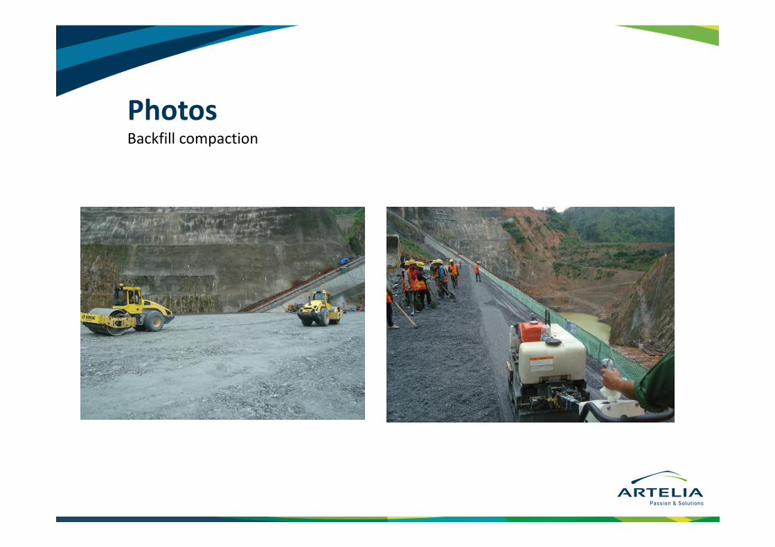
PhotosBackfill compaction

PhotosExtruded concrete

PhotosPlinth

Thank you for your attention